EP4134999A1 - X-ray generator and x-ray generation method - Google Patents
X-ray generator and x-ray generation method Download PDFInfo
- Publication number
- EP4134999A1 EP4134999A1 EP21789322.1A EP21789322A EP4134999A1 EP 4134999 A1 EP4134999 A1 EP 4134999A1 EP 21789322 A EP21789322 A EP 21789322A EP 4134999 A1 EP4134999 A1 EP 4134999A1
- Authority
- EP
- European Patent Office
- Prior art keywords
- electron beam
- magnetic
- sectional shape
- lens
- electron
- Prior art date
- Legal status (The legal status is an assumption and is not a legal conclusion. Google has not performed a legal analysis and makes no representation as to the accuracy of the status listed.)
- Pending
Links
- 238000000034 method Methods 0.000 title claims description 14
- 230000005291 magnetic effect Effects 0.000 claims abstract description 197
- 238000010894 electron beam technology Methods 0.000 claims abstract description 189
- 230000004044 response Effects 0.000 claims abstract description 7
- 238000000605 extraction Methods 0.000 claims description 8
- 238000010586 diagram Methods 0.000 description 9
- 230000008859 change Effects 0.000 description 6
- 238000007689 inspection Methods 0.000 description 5
- 230000000052 comparative effect Effects 0.000 description 4
- 230000007423 decrease Effects 0.000 description 4
- 239000000463 material Substances 0.000 description 4
- 230000006866 deterioration Effects 0.000 description 3
- 229910052751 metal Inorganic materials 0.000 description 3
- 239000002184 metal Substances 0.000 description 3
- 230000002093 peripheral effect Effects 0.000 description 3
- XEEYBQQBJWHFJM-UHFFFAOYSA-N Iron Chemical compound [Fe] XEEYBQQBJWHFJM-UHFFFAOYSA-N 0.000 description 2
- 230000004075 alteration Effects 0.000 description 2
- 230000003247 decreasing effect Effects 0.000 description 2
- 238000002474 experimental method Methods 0.000 description 2
- 230000020169 heat generation Effects 0.000 description 2
- 230000009467 reduction Effects 0.000 description 2
- RYGMFSIKBFXOCR-UHFFFAOYSA-N Copper Chemical compound [Cu] RYGMFSIKBFXOCR-UHFFFAOYSA-N 0.000 description 1
- 229910000881 Cu alloy Inorganic materials 0.000 description 1
- ZOKXTWBITQBERF-UHFFFAOYSA-N Molybdenum Chemical compound [Mo] ZOKXTWBITQBERF-UHFFFAOYSA-N 0.000 description 1
- BQCADISMDOOEFD-UHFFFAOYSA-N Silver Chemical compound [Ag] BQCADISMDOOEFD-UHFFFAOYSA-N 0.000 description 1
- 229910045601 alloy Inorganic materials 0.000 description 1
- 239000000956 alloy Substances 0.000 description 1
- 239000006227 byproduct Substances 0.000 description 1
- 229910052802 copper Inorganic materials 0.000 description 1
- 239000010949 copper Substances 0.000 description 1
- 230000000694 effects Effects 0.000 description 1
- 230000005294 ferromagnetic effect Effects 0.000 description 1
- 229910001385 heavy metal Inorganic materials 0.000 description 1
- 229910052742 iron Inorganic materials 0.000 description 1
- 239000007769 metal material Substances 0.000 description 1
- 229910052750 molybdenum Inorganic materials 0.000 description 1
- 239000011733 molybdenum Substances 0.000 description 1
- 230000003287 optical effect Effects 0.000 description 1
- 229910052703 rhodium Inorganic materials 0.000 description 1
- 239000010948 rhodium Substances 0.000 description 1
- MHOVAHRLVXNVSD-UHFFFAOYSA-N rhodium atom Chemical compound [Rh] MHOVAHRLVXNVSD-UHFFFAOYSA-N 0.000 description 1
- 229910052709 silver Inorganic materials 0.000 description 1
- 239000004332 silver Substances 0.000 description 1
- WFKWXMTUELFFGS-UHFFFAOYSA-N tungsten Chemical compound [W] WFKWXMTUELFFGS-UHFFFAOYSA-N 0.000 description 1
- 229910052721 tungsten Inorganic materials 0.000 description 1
- 239000010937 tungsten Substances 0.000 description 1
- 238000011144 upstream manufacturing Methods 0.000 description 1
- 238000004846 x-ray emission Methods 0.000 description 1
Images




Classifications
-
- H—ELECTRICITY
- H01—ELECTRIC ELEMENTS
- H01J—ELECTRIC DISCHARGE TUBES OR DISCHARGE LAMPS
- H01J35/00—X-ray tubes
- H01J35/02—Details
- H01J35/04—Electrodes ; Mutual position thereof; Constructional adaptations therefor
- H01J35/06—Cathodes
- H01J35/066—Details of electron optical components, e.g. cathode cups
-
- H—ELECTRICITY
- H01—ELECTRIC ELEMENTS
- H01J—ELECTRIC DISCHARGE TUBES OR DISCHARGE LAMPS
- H01J35/00—X-ray tubes
- H01J35/02—Details
- H01J35/14—Arrangements for concentrating, focusing, or directing the cathode ray
- H01J35/147—Spot size control
-
- H—ELECTRICITY
- H01—ELECTRIC ELEMENTS
- H01J—ELECTRIC DISCHARGE TUBES OR DISCHARGE LAMPS
- H01J35/00—X-ray tubes
- H01J35/02—Details
- H01J35/04—Electrodes ; Mutual position thereof; Constructional adaptations therefor
- H01J35/06—Cathodes
- H01J35/064—Details of the emitter, e.g. material or structure
-
- H—ELECTRICITY
- H01—ELECTRIC ELEMENTS
- H01J—ELECTRIC DISCHARGE TUBES OR DISCHARGE LAMPS
- H01J35/00—X-ray tubes
- H01J35/02—Details
- H01J35/04—Electrodes ; Mutual position thereof; Constructional adaptations therefor
- H01J35/08—Anodes; Anti cathodes
-
- H—ELECTRICITY
- H01—ELECTRIC ELEMENTS
- H01J—ELECTRIC DISCHARGE TUBES OR DISCHARGE LAMPS
- H01J35/00—X-ray tubes
- H01J35/02—Details
- H01J35/14—Arrangements for concentrating, focusing, or directing the cathode ray
-
- H—ELECTRICITY
- H01—ELECTRIC ELEMENTS
- H01J—ELECTRIC DISCHARGE TUBES OR DISCHARGE LAMPS
- H01J35/00—X-ray tubes
- H01J35/02—Details
- H01J35/16—Vessels; Containers; Shields associated therewith
-
- H—ELECTRICITY
- H01—ELECTRIC ELEMENTS
- H01J—ELECTRIC DISCHARGE TUBES OR DISCHARGE LAMPS
- H01J35/00—X-ray tubes
- H01J35/24—Tubes wherein the point of impact of the cathode ray on the anode or anticathode is movable relative to the surface thereof
- H01J35/26—Tubes wherein the point of impact of the cathode ray on the anode or anticathode is movable relative to the surface thereof by rotation of the anode or anticathode
-
- H—ELECTRICITY
- H01—ELECTRIC ELEMENTS
- H01J—ELECTRIC DISCHARGE TUBES OR DISCHARGE LAMPS
- H01J2235/00—X-ray tubes
- H01J2235/16—Vessels
- H01J2235/165—Shielding arrangements
- H01J2235/168—Shielding arrangements against charged particles
-
- H—ELECTRICITY
- H01—ELECTRIC ELEMENTS
- H01J—ELECTRIC DISCHARGE TUBES OR DISCHARGE LAMPS
- H01J2235/00—X-ray tubes
- H01J2235/20—Arrangements for controlling gases within the X-ray tube
Definitions
- the emission direction of the X-ray XR is orthogonal to the traveling direction of the electron beam EB. Accordingly, it may be understood that the X-axis direction (first direction) is parallel to the traveling direction of the electron beam EB, a Z-axis direction (second direction) is parallel to the emission direction of the X-ray XR from the target 31, and a Y-axis direction (third direction) is orthogonal to the X-axis direction and the Z-axis direction.
- the angular deviation may be eliminated by changing the traveling direction of the electron beam EB to a direction along the central axis by means of the deflection coil 41.
- two-dimensional deflection can be performed by the deflection coil 41 in order to correct not only the angular deviation but also a lateral offset between the emission axis and the central axis (such as when the emission axis and the central axis are parallel to each other in the X-axis direction and separated from each other in one or both of the Y-axis and Z-axis directions).
- a voltage is applied to the electron gun 2 in a state where the internal spaces S1 and S2 and the electron passage P are suctioned by the exhaust system.
- the electron beam EB having the circular cross-sectional shape is emitted from the electron gun 2.
- the electron beam EB is focused on the target 31 and deformed so as to have an elliptical cross-sectional shape by the magnetic lens 4, and the electron beam EB is incident on the rotating target 31.
- the X-ray XR is generated at the target 31 and the X-ray XR having a substantially circular effective focal point shape is emitted outside the housing 7 from the X-ray passage hole 7a.
- the performance of the example X-ray generation apparatus 1 provided with the electron gun 2 and magnetic lens 4 was evaluated by conducting an experiment. During the experiment, a high voltage was applied to the electron gun 2 and the target 31 was set to the ground potential. The X-ray XR having an effective focal point dimension of "40 ⁇ m ⁇ 40 ⁇ m" was obtained at a preselected output (voltage applied to the cathode C). In the case of a change in focal dimension during a 1,000-hour operation, the effective focal point dimension was readily obtained again by the electric current amount of the coil 43d of the magnetic quadrupole lens 43 being adjusted without a change in the operating condition on the cathode C side. In this manner, it has been confirmed that the effective focal point dimension of the X-ray XR may be readily corrected in accordance with a dynamic change by performing an adjustment of the electric current amount of the coil 43d with the X-ray generation apparatus 1.
- the X-ray generation apparatus 1 includes: means (e.g., an electron gun 2) for emitting an electron beam EB having a circular cross-sectional shape; means (e.g., a magnetic focusing lens 42) for focusing the electron beam EB while rotating the electron beam EB around a rotational axis; means (e.g., a magnetic quadrupole lens 43) for deforming the circular cross-sectional shape of the electron beam EB into an elliptical cross-sectional shape, wherein the elliptical cross-sectional shape has a major axis X1 that is orthogonal to the rotational axis and a minor axis X2 that is orthogonal to both the rotational axis and the major axis X1; and means (e.g., a target 31) for emitting an X-ray XR in response to receiving the electron beam EB having the elliptical cross-sectional shape.
- means e.g., an electron gun 2 for emitting
- the means for focusing the electron beam includes a first magnetic lens (a magnetic focusing lens 42).
- the means for deforming the cross-sectional shape of the electron beam includes a second magnetic lens (a magnetic quadrupole lens 43).
- the means for adjusting includes: means (e.g., one of two deflection coils included in the deflection coil 41) for correcting an angular deviation between the rotational axis of the electron beam EB and a central axis that passes through both the first magnetic lens and the second magnetic lens; and means (e.g., the other of the two deflection coils included in the deflection coil 41) for correcting a lateral offset between the rotational axis of the electron beam EB and the central axis.
Landscapes
- X-Ray Techniques (AREA)
Abstract
Description
- An aspect of the present disclosure relates to an X-ray generation apparatus and a method of generating an X-ray.
- Known X-ray devices may generate an X-ray by causing an electron beam emitted from a cathode to be incident on a target. For example, Patent Document 1 describes a reflective target having an electron incident surface inclined with respect to the traveling direction of an electron beam. Additionally,
Patent Document 2 describes adjusting a cross-sectional shape of an electron beam. -
- [Patent Document 1]
Japanese Unexamined Patent Publication No. 2006-164819 - [Patent Document 2]
Japanese Patent No. 6527239 - In some X-ray devices, the focal point (effective focal point) of the extracted X-ray is not the shape of the electron beam incident on the target (that is, the shape of the electron beam viewed from the direction of incidence) but a projected shape viewed from the extraction direction (X-ray emission direction). In addition, the longitudinal and lateral dimensions of the effective focal point match each other (that is, the shape of the effective focal point is a substantially circular shape) for an image having the same resolution in the longitudinal and lateral directions to be obtained in an inspection using X-rays or the like. An elliptical beam cross section of the electron beam incident on the target may be used as a method for achieving a substantially circular effective focal point.
- An inadvertent change in the cross-sectional shape of the electron beam may be attributable to, for example, the deterioration of one or more components of the X-ray device. However, if the cross-sectional shape of the electron beam is determined by the opening shape of the grid electrode, this may prohibit the ability to change or correct a shape formed by the X-ray device, such as the aspect ratio between the major axis and the minor axis of an elliptical shape.
- Additionally, for certain types of X-ray devices which use two quadrupole cores for adjusting a cross-sectional shape of an electron beam, it can be difficult to simultaneously adjust both the aspect ratio of the cross-sectional shape of the electron beam and the size of the electron beam, such as by combining the two quadrupole cores.
- Disclosed herein are example X-ray generation apparatuses with which the aspect ratio and size of a cross-sectional shape of an electron beam can be readily and flexibly adjusted.
- An example X-ray generation apparatus includes an electron gun configured to emit an electron beam having a circular cross-sectional shape, a magnetic focusing lens located downstream of the electron gun and configured to focus the electron beam while rotating the electron beam around an axis (rotational axis) along a first direction. Additionally, the X-ray generation apparatus may include a magnetic quadrupole lens located downstream of the magnetic focusing lens and configured to deform the circular cross-sectional shape of the electron beam into an elliptical cross-sectional shape having a major axis along a second direction orthogonal to the first direction and a minor axis along a third direction that is orthogonal to both the first direction and the second direction. Still further, the X-ray generation apparatus may include a target located downstream of the magnetic quadrupole lens and configured to emit an X-ray in response to an incidence of the electron beam on the target.
- In some examples, the size of the electron beam is adjusted by the magnetic focusing lens located downstream of the electron gun and the cross-sectional shape of the electron beam is deformed into an elliptical shape by the magnetic quadrupole lens located downstream of the magnetic focusing lens. Accordingly, the size of the electron beam and the cross-sectional shape can be adjusted independently of each other. In addition, although the electron beam passing through the magnetic focusing lens rotates around an axis along the first direction, the cross-sectional shape of the electron beam reaching the magnetic quadrupole lens through the magnetic focusing lens is constant (circular) regardless of the amount of rotation of the electron beam in the magnetic focusing lens since the cross-sectional shape of the electron beam emitted by the electron gun is circular. The cross-sectional shape of the electron beam in the magnetic quadrupole lens can therefore be consistently and reliably formed into an elliptical shape having a major axis along the second direction and a minor axis along the third direction. As a result, the size and the aspect ratio of the cross-sectional shape of the electron beam may be readily and flexibly adjusted.
- The target may have an electron incident surface on which the electron beam is incident. The electron incident surface may be inclined with respect to the first direction and the second direction. A ratio between the major and minor axes of the electron beam subsequent to the deformation into the elliptical cross-sectional shape by the magnetic quadrupole lens, and an inclination angle of the electron incident surface with respect to the first direction and the second direction, determine a focal shape of the X-ray, when viewed from an extraction direction of the X-ray, that is substantially circular. Accordingly, the shape of the focal point (effective focal point) of the extracted X-ray can be made substantially circular by adjusting the forming condition of the magnetic quadrupole lens (aspect ratio) and the inclination angle of the electron incident surface of the target. As a result, an appropriate inspection image may be obtained during, for example, an X-ray inspection using the X-ray generated by the X-ray generation apparatus.
- A length of the magnetic focusing lens along the first direction may exceed a length of the magnetic quadrupole lens along the first direction. In some examples, the number of turns of a coil of the magnetic focusing lens may be reliably ensured in order to effectively focus the electron beam by generating a relatively large magnetic field in the magnetic focusing lens. Accordingly, the reduction ratio may be increased. Further, the distance from the electron gun to the center of the lens constituted by the magnetic focusing lens may be increased in order to reduce the size of the electron beam incident on the electron incident surface of the target.
- An inner diameter of a pole piece of the magnetic focusing lens may exceed an inner diameter of the magnetic quadrupole lens. In some examples, the spherical aberration of the lens constituted by the magnetic focusing lens may be reduced by making the inner diameter of the pole piece of the magnetic focusing lens relatively large. In addition, the number of turns of a coil in the magnetic quadrupole lens may be reduced, and the amount of electric current flowing through the coil may be reduced, by making the inner diameter of the magnetic quadrupole lens relatively small. As a result, the amount of heat generation in the magnetic quadrupole lens can be reduced.
- The X-ray generation apparatus may further include a tubular portion extending along the first direction and forming an electron passage through which the electron beam passes. The magnetic focusing lens and the magnetic quadrupole lens may be directly or indirectly connected to the tubular portion. In some examples, the magnetic focusing lens and the magnetic quadrupole lens can be disposed or attached with respect to the tubular portion as a reference, and thus the central axes of the magnetic focusing lens and the magnetic quadrupole lens can be coaxially disposed with high precision. As a result, a distortion of the profile (cross-sectional shape) of the electron beam which may have otherwise occurred subsequent to passage through the magnetic focusing lens and the magnetic quadrupole lens may be forestalled or prevented.
- Additionally, the X-ray generation apparatus may further include a deflection coil configured to adjust a traveling direction of the electron beam. In some examples, the deflection coil may be configured to correct an angular deviation between the emission axis of the electron beam emitted from the electron gun and the central axis of the magnetic focusing lens and the magnetic quadrupole lens. For example, the angular deviation may occur in a case where the emission axis and the central axis intersect with each other at a predetermined angle. Accordingly, the angular deviation may be eliminated by changing the traveling direction of the electron beam to a direction along the central axis by means of the deflection coil.
- The deflection coil may be located between the electron gun and the magnetic focusing lens. In some examples, the traveling direction of the electron beam may be preferentially adjusted before the electron beam passes through the magnetic focusing lens and the magnetic quadrupole lens. As a result, the cross-sectional shape of the electron beam incident on the target may be reliably maintained as an intended elliptical shape.
- Accordingly, the example X-ray generation apparatuses disclosed herein may be configured to reliably and flexibly adjust the aspect ratio and size of a cross-sectional shape of an electron beam.
-
-
FIG. 1 is a schematic configuration diagram of an example X-ray generation apparatus. -
FIG. 2 is a schematic cross-sectional view illustrating an example configuration of a magnetic lens of the X-ray generation apparatus. -
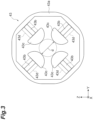
FIG. 3 is a front view of an example magnetic quadrupole lens. -
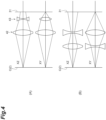
FIG. 4 is a schematic diagram of an example configuration including a magnetic focusing lens and a magnetic quadrupole lens and a configuration of a comparative example (doublet). -
FIG. 5 is a diagram illustrating an example relationship between a cross-sectional shape of an electron beam and the shape of an effective focal point of an X-ray. -
FIG. 6 is a diagram illustrating an example cylindrical tube. -
FIG. 7 is a diagram illustrating another example cylindrical tube. -
FIG. 8 is a schematic configuration diagram of another example X-ray generation apparatus. - In the following description, with reference to the drawings, the same reference numbers are assigned to the same components or to similar components having the same function, and overlapping description is omitted.
- As illustrated in
FIG. 1 , an example X-ray generation apparatus 1 is provided with anelectron gun 2, arotary anode unit 3, amagnetic lens 4, anexhaust unit 5, a housing 6 (first housing) defining an internal space S1 accommodating theelectron gun 2, and a housing 7 (second housing) defining an internal space S2 accommodating therotary anode unit 3. Thehousing 6 and thehousing 7 may be configured to be detachable from each other, may be integrally coupled so as not to be detachable from each other, or may be integrally formed from the beginning. - The
electron gun 2 emits an electron beam EB. Theelectron gun 2 has a cathode C emitting the electron beam EB. The cathode C is a circular flat cathode emitting the electron beam EB having a circular cross-sectional shape. The cross-sectional shape of the electron beam EB is taken in a direction perpendicular to an X-axis direction (first direction), which is parallel to the traveling direction of the electron beam EB that will be described in additional detail later. Accordingly, the cross-sectional shape of the electron beam EB may be understood to be taken on a YZ plane. The electron emission surface of the cathode C itself may have, for example, a circular shape when viewed from a position facing the electron emission surface of the cathode C (when the electron emission surface of the cathode C is viewed from the X-axis direction) so as to form the electron beam EB having the circular cross-sectional shape. - The
rotary anode unit 3 has atarget 31, arotary support body 32, and adrive unit 33 that drives therotary support body 32 to rotate around a rotation axis A. Thetarget 31 is provided along the peripheral edge portion of therotary support body 32 formed in a flat truncated cone shape. The rotation axis A is a central axis of therotary support body 32, such that the side surface of the truncated cone-shapedrotary support body 32 has a surface inclined with respect to the rotation axis A. Additionally, therotary support body 32 may be formed in an annular shape having the rotation axis A as a central axis. The material that constitutes thetarget 31 may comprise, for example, a heavy metal such as tungsten, silver, rhodium, molybdenum, or an alloy thereof. Therotary support body 32 is rotatable around the rotation axis A. The material that constitutes therotary support body 32 may comprise, for example, a metal such as copper or a copper alloy. Thedrive unit 33 has a drive source, such as a motor, that drives therotary support body 32 to rotate around the rotation axis A. Thetarget 31 receives the electron beam EB while rotating with the rotation of therotary support body 32. An X-ray XR is generated as a result. The X-ray XR is emitted outside of thehousing 7 from anX-ray passage hole 7a formed in thehousing 7. Awindow member 8 forms an air-tight seal at theX-ray passage hole 7a. The axial direction of the rotation axis A is parallel to the incident direction of the electron beam EB on thetarget 31. Alternatively, the rotation axis A may be inclined with respect to the incident direction of the electron beam EB on thetarget 31 so that the rotation axis A may extend in a direction intersecting with the incident direction. Thetarget 31, which may comprise a reflective target, emits the X-ray XR in a direction intersecting with the traveling direction of the electron beam EB (direction of incidence on the target 31). In some examples, the emission direction of the X-ray XR is orthogonal to the traveling direction of the electron beam EB. Accordingly, it may be understood that the X-axis direction (first direction) is parallel to the traveling direction of the electron beam EB, a Z-axis direction (second direction) is parallel to the emission direction of the X-ray XR from thetarget 31, and a Y-axis direction (third direction) is orthogonal to the X-axis direction and the Z-axis direction. - The
magnetic lens 4 controls the electron beam EB. Themagnetic lens 4 has adeflection coil 41, a magnetic focusinglens 42, amagnetic quadrupole lens 43, and ahousing 44. Thehousing 44 accommodates thedeflection coil 41, the magnetic focusinglens 42, and themagnetic quadrupole lens 43. Thedeflection coil 41, the magnetic focusinglens 42, and themagnetic quadrupole lens 43 are located within thehousing 44, in this order, from a direction of theelectron gun 2 toward thetarget 31 along the X-axis. An electron passage P through which the electron beam EB passes is formed between theelectron gun 2 and thetarget 31. As illustrated inFIG. 2 , the electron passage P may be formed by a cylindrical tube 9 (tubular portion). Thecylindrical tube 9 is a nonmagnetic metal member extending along the X-axis direction between theelectron gun 2 and thetarget 31. Additional example configurations of thecylindrical tube 9 will be described in further detail later. - The
deflection coil 41, the magnetic focusinglens 42, and themagnetic quadrupole lens 43 are directly or indirectly connected to thecylindrical tube 9. For example, the central axis of thedeflection coil 41, the central axis of the magnetic focusinglens 42, and the central axis of themagnetic quadrupole lens 43 are coaxially disposed with high precision by thedeflection coil 41, the magnetic focusinglens 42, and themagnetic quadrupole lens 43 being assembled with respect to thecylindrical tube 9 as a reference. Accordingly, the central axis of thedeflection coil 41, the central axis of the magnetic focusinglens 42, and the central axis of themagnetic quadrupole lens 43 coincide with the central axis of the cylindrical tube 9 (axis parallel to the X axis). - The
deflection coil 41 is located between theelectron gun 2 and the magnetic focusinglens 42. Thedeflection coil 41 is disposed so as to surround the electron passage P. In some examples, thedeflection coil 41 is indirectly connected to thecylindrical tube 9 via atube member 10. Thetube member 10 is a nonmagnetic metal member extending coaxially with thecylindrical tube 9. Thetube member 10 is provided so as to cover the outer periphery of thecylindrical tube 9. Thedeflection coil 41 is positioned by the outer peripheral surface of thetube member 10 and the surface of awall portion 44a that is on thetarget 31 side. Thewall portion 44a, which is made of a nonmagnetic material, is a part of thehousing 44 provided at a position facing the internal space S 1. Thedeflection coil 41 adjusts the traveling direction of the electron beam EB emitted from theelectron gun 2. One deflection coil (one set of deflection coils) or two deflection coils (two sets of deflection coils) may constitute thedeflection coil 41. In the former case that involves one deflection coil, thedeflection coil 41 may be configured to correct an angular deviation between the emission axis of the electron beam EB emitted from theelectron gun 2 and the central axis of the magnetic focusinglens 42 and the magnetic quadrupole lens 43 (axis parallel to the X axis). For example, the angular deviation may occur in a case where the emission axis and the central axis intersect with each other at a predetermined angle. Accordingly, the angular deviation may be eliminated by changing the traveling direction of the electron beam EB to a direction along the central axis by means of thedeflection coil 41. In the latter case that involves two deflection coils, two-dimensional deflection can be performed by thedeflection coil 41 in order to correct not only the angular deviation but also a lateral offset between the emission axis and the central axis (such as when the emission axis and the central axis are parallel to each other in the X-axis direction and separated from each other in one or both of the Y-axis and Z-axis directions). - The magnetic focusing
lens 42 is located downstream of theelectron gun 2 and thedeflection coil 41. The magnetic focusinglens 42 focuses the electron beam EB while rotating the electron beam EB around an axis along the X-axis direction. In some examples, the electron beam EB passing through the magnetic focusinglens 42 is focused while rotating in a spiral shape. The magnetic focusinglens 42 has apole piece 42b, ayoke 42c, ayoke 42d, and acoil 42a disposed so as to surround the electron passage P. Theyoke 42c also functions as awall portion 44b of thehousing 44 provided so as to interconnect thetube member 10 and a part of the outside of thecoil 42a. Theyoke 42d is a tubular member provided so as to cover the outer periphery of thetube member 10. In some examples, thecoil 42a is indirectly connected to thecylindrical tube 9 via thetube member 10 and theyoke 42d. Theyoke 42c and theyoke 42d constitute thepole piece 42b. Theyoke 42c and theyoke 42d are ferromagnetic bodies such as iron. Additionally, thepole piece 42b may be constituted by a notch (gap) provided between theyoke 42c and theyoke 42d, and a part of theyoke 42c and a part of theyoke 42d positioned near the notch. An inner diameter D of thepole piece 42b is equal to the inner diameter of the region of theyoke 42c or theyoke 42d that is adjacent to the gap. Accordingly, the magnetic focusinglens 42 may be configured such that the magnetic field of thecoil 42a leaks from thepole piece 42b to thecylindrical tube 9 side. - The
magnetic quadrupole lens 43 is located downstream of the magnetic focusinglens 42. Themagnetic quadrupole lens 43 deforms the cross-sectional shape of the electron beam EB into an elliptical shape having a major axis along the Z-axis direction and a minor axis along the Y-axis direction. Themagnetic quadrupole lens 43 is disposed so as to surround the electron passage P. In some examples, themagnetic quadrupole lens 43 is indirectly connected to thecylindrical tube 9 via awall portion 44c of thehousing 44. Thewall portion 44c is connected to thewall portion 44b and is provided so as to cover the outer periphery of thecylindrical tube 9. Thewall portion 44c is made of a nonmagnetic metal material. - As illustrated in
FIG. 3 , the examplemagnetic quadrupole lens 43 has anannular yoke 43a, fourcolumnar yokes 43b provided on the inner peripheral surface of theyoke 43a, and yokes 43c respectively provided at the distal ends of thecolumnar yokes 43b. Acoil 43d is wound around thecolumnar yoke 43b. Theyokes 43c each have a substantially semicircular cross-sectional shape on the YZ plane. An inner diameter d of themagnetic quadrupole lens 43 is the diameter of an inscribed circle passing through the respective innermost ends of theyokes 43c. Themagnetic quadrupole lens 43 functions as a concave lens on the XZ plane (plane orthogonal to the Y-axis direction) and functions as a convex lens on the XY plane (plane orthogonal to the Z-axis direction). As a result of this function of themagnetic quadrupole lens 43, the aspect ratio between the diameter (major axis X1) of the electron beam EB along the Z-axis direction and the diameter (minor axis X2) of the electron beam EB along the Y-axis direction is adjusted such that the Z-axis-direction length of the electron beam EB is greater than the Y-axis-direction length of the electron beam EB. Accordingly, the aspect ratio may be selectively modified by adjusting the amount of electric current flowing through thecoil 43d. As an example, the aspect ratio between the major axis X1 and the minor axis X2 is adjusted to "10 : 1". - The
exhaust unit 5 has avacuum pump 5a (first vacuum pump) and avacuum pump 5b (second vacuum pump). Thehousing 6 is provided with an exhaust flow path E1 (first exhaust flow path) for evacuating the space in the housing 6 (the internal space S1 defined by thehousing 6 and thehousing 44 of the magnetic lens 4). Thevacuum pump 5b and the internal space S1 communicate (e.g., are fluidly coupled) with each other via the exhaust flow path E1. Thehousing 7 is provided with an exhaust flow path E2 (second exhaust flow path) for evacuating the space in the housing 7 (the internal space S2 defined by the housing 7). Thevacuum pump 5a and the internal space S2 communicate (e.g., are fluidly coupled) with each other via the exhaust flow path E2. Thevacuum pump 5b evacuates the internal space S1 via the exhaust flow path E1. Thevacuum pump 5a evacuates the internal space S2 via the exhaust flow path E2. As a result, the internal space S1 and the internal space S2 are maintained in a vacuumized state or a partial vacuum, for example in order to remove any gas that is generated by the electron gun or at the target, as further described herein. The internal pressure in the internal space S1 may be preferably maintained in a partial vacuum of less than or equal to 10-4 Pa and may be more preferably maintained in a partial vacuum of less than or equal to 10-5 Pa. The internal pressure in the internal space S2 may be preferably maintained in a partial vacuum of between 10-6 Pa and 10-3 Pa. The internal space of the cylindrical tube 9 (space in the electron passage P) is also evacuated by theexhaust unit 5 via the internal space S1 or the internal space S2. - As illustrated in
FIG. 8 , the use of the two exhaust pumps (vacuum pumps FIG. 1 may be replaced with an example structure (X-ray generation apparatus 1A) in which both the internal space S1 and the internal space S2 can be evacuated by means of one exhaust pump (here, thevacuum pump 5b as an example). In some examples, the exhaust flow path E1 and the exhaust flow path E2 may be fluidly coupled to each other by means of a communication path E3 located outside thehousing 6 and thehousing 7. In other examples, the communication path E3 may comprise a through hole continuously provided from the inside of the wall portion of thehousing 7 to the inside of the wall portion of thehousing 6 so as to fluidly couple the exhaust flow path E1 and the exhaust flow path E2 to each other. Although either thevacuum pump 5a or thevacuum pump 5b may be used as the single exhaust pump, more efficient evacuation can be performed by thevacuum pump 5b fluidly coupled to the exhaust flow path E1 being used as the exhaust pump. - In some examples, a voltage is applied to the
electron gun 2 in a state where the internal spaces S1 and S2 and the electron passage P are suctioned by the exhaust system. As a result, the electron beam EB having the circular cross-sectional shape is emitted from theelectron gun 2. The electron beam EB is focused on thetarget 31 and deformed so as to have an elliptical cross-sectional shape by themagnetic lens 4, and the electron beam EB is incident on therotating target 31. When the electron beam EB is incident on thetarget 31, the X-ray XR is generated at thetarget 31 and the X-ray XR having a substantially circular effective focal point shape is emitted outside thehousing 7 from theX-ray passage hole 7a. - As illustrated in
FIG. 2 , an example configuration of thecylindrical tube 9 has a shape in which the size of the diameter of thecylindrical tube 9 changes in stages along the X-axis direction. For example, thecylindrical tube 9 has sixcylindrical portions 91 to 96 located along the X-axis direction. Each of thecylindrical portions 91 to 96 has a constant diameter along the X-axis direction. In some examples, the outer diameter of thecylindrical tube 9 may not change in synchronization with the inner diameter of thecylindrical tube 9. Accordingly, the outer diameter of thecylindrical tube 9 may be constant. - The cylindrical portion 91 (e.g., a first cylindrical portion) includes a
first end portion 9a of thecylindrical tube 9, which is on theelectron gun 2 side of thecylindrical portion 91. Thecylindrical portion 91 extends from thefirst end portion 9a to asecond end portion 91a surrounded by a portion of thecoil 42a on theelectron gun 2 side of thecylindrical portion 91 at aboundary part 9c. Afirst end portion 92a of the cylindrical portion 92 (e.g., a second cylindrical portion) is connected to thesecond end portion 91a of thecylindrical portion 91 on thetarget 31 side of thecylindrical portion 91. In some examples, thecylindrical portion 92 extends from thesecond end portion 91a of thecylindrical portion 91 to a second end portion 92b of thecylindrical portion 92 which is slightly closer to thetarget 31 than thepole piece 42b. For example, the second end portion 92b of thecylindrical portion 92 may be located between thepole piece 42b and thetarget 31 along the X-axis direction. Additionally, a first end portion 93a of the cylindrical portion 93 (e.g., a third cylindrical portion) is connected to the second end portion 92b of thecylindrical portion 92 on thetarget 31 side of thecylindrical portion 92. - The cylindrical portion 93 extends from the second end portion 92b of the
cylindrical portion 92 to asecond end portion 93b of the cylindrical portion 93 which is surrounded by themagnetic quadrupole lens 43. A first end of the cylindrical portion 94 (e.g., a fourth cylindrical portion) is connected to thesecond end portion 93b of the cylindrical portion 93 on thetarget 31 side of the cylindrical portion 93. Thecylindrical portion 94 extends from thesecond end portion 93b of the cylindrical portion 93 to ahousing side 7 of thewall portion 44c. - The cylindrical portion 95 (e.g., a fifth cylindrical portion) and the cylindrical portion 96 (e.g., a sixth cylindrical portion) pass through an inside of a
wall portion 71 of thehousing 7. Thewall portion 71 is located at a position facing thetarget 31 and extends so as to intersect with the X-axis direction. Thecylindrical portion 95 is connected to a second end of thecylindrical portion 94 on thetarget 31 side of thecylindrical portion 94. Thecylindrical portion 95 extends from the end of thecylindrical portion 94 to an intermediate position in thewall portion 71. Thecylindrical portion 96 is connected to thecylindrical portion 95 at the intermediate position in thewall portion 71, on thetarget 31 side of thecylindrical portion 95. Thecylindrical portion 96 extends from the end of thecylindrical portion 95 to asecond end portion 9b of thecylindrical tube 9 on thetarget 31 side of thecylindrical tube 9. As illustrated inFIG. 2 , the exampleX-ray passage hole 7a is provided in awall portion 72 connected to thewall portion 71 and extending so as to intersect with the Z-axis direction. TheX-ray passage hole 7a penetrates thewall portion 72 along the Z-axis direction. - In some examples, a relationship of "d2 > d3 > d1 > d4 > d5 > d6" is established when the diameters of the six
cylindrical portions 91 to 96 are d1 to d6, respectively. As an example, a first diameter d1 is 6 to 12 mm, a second diameter d2 is 10 to 14 mm, a third diameter d3 is 8 to 12 mm, a fourth diameter d4 is 4 to 6 mm, a fifth diameter d5 is 4 to 6 mm, and a sixth diameter d6 is 0.5 to 4 mm. - The
cylindrical portion 91 and at least a part of thecylindrical portion 92 are positioned closer to theelectron gun 2 than the part of the electron passage P that is surrounded by thepole piece 42b of the magnetic focusing lens 42 (gap between theyoke 42c and theyoke 42d in particular). In some examples, thecylindrical portion 91 and the at least part of thecylindrical portion 92 constitute the "part of the electron passage P that is closer to theelectron gun 2 than the part of the electron passage P surrounded by thepole piece 42b of the magnetic focusinglens 42" (hereinafter, referred to as the "first cylindrical part"). Further, as described above, the diameter d2 of thecylindrical portion 92 is larger than the diameter d1 of the cylindrical portion 91 (d2 > d1). Accordingly, thecylindrical portion 92 is larger in diameter than thecylindrical portion 91 adjacent to theelectron gun 2 side. In some examples, at the first cylindrical part, at least a part of thecylindrical portion 92 constitutes a diameter-increased portion that increases in diameter toward thetarget 31 side of thecylindrical portion 92. - The
cylindrical portion 96 includes theend portion 9b of the electron passage P on thetarget 31 side of the electron passage P. Further, the diameter d6 of thecylindrical portion 96 is smaller than the diameter d5 of the cylindrical portion 95 (d6 < d5). Accordingly, thecylindrical portion 96 is smaller in diameter than thecylindrical portion 95 adjacent to theelectron gun 2 side such that thecylindrical portion 96 constitutes a diameter-reduced portion that decreases in diameter toward thetarget 31 side of thecylindrical portion 96. In some examples, the diameter d2 of thecylindrical portion 92 is the maximum diameter of thecylindrical tube 9 that sequentially decreases from thecylindrical portion 92 toward thetarget 31 side of thecylindrical tube 9. Accordingly, the part of thecylindrical tube 9 including the cylindrical portions 93 to 96 can be regarded as constituting the diameter-reduced portion. - In some examples, the size of the electron beam EB is adjusted by the magnetic focusing
lens 42 located downstream of theelectron gun 2 and the cross-sectional shape of the electron beam EB is deformed into an elliptical shape by themagnetic quadrupole lens 43 located downstream of the magnetic focusinglens 42. Accordingly, the size of the electron beam EB and the cross-sectional shape can be adjusted independently of each other. - (A) of
FIG. 4 illustrates a schematic diagram of an example configuration including the magnetic focusinglens 42 and themagnetic quadrupole lens 43 illustrated inFIGS. 1 and2 .(B) ofFIG. 4 is a schematic diagram of a configuration of a comparative example (doublet). (A) and (B) ofFIG. 4 are diagrams schematically illustrating an example optical system acting on the electron beam EB between the cathode C (electron gun 2) and thetarget 31. As illustrated in the configuration of the comparative example at (B) ofFIG. 4 , the aspect ratio and the size of the cross-sectional shape of the electron beam are adjusted by the combination of a two-stage magnetic quadrupole lens in which surfaces acting as concave and convex lenses are replaced with each other. In the comparative example of (B) ofFIG. 4 , the lens that determines the size of the cross-sectional shape of the electron beam and the lens that determines the aspect ratio are not independent of each other. Accordingly, the size and the aspect ratio are simultaneously adjusted by combining the two-stage magnetic quadrupole lens, which can complicate the focal dimension adjustment and focal shape adjustment. In the example configuration illustrated in (A) ofFIG. 4 , in contrast, the size of the cross-sectional shape of the electron beam EB is adjusted by the upstream magnetic focusinglens 42. Accordingly, the cross-sectional shape of the electron beam EB is reduced to a certain size by the magnetic focusinglens 42. Subsequently, the aspect ratio of the cross-sectional shape of the electron beam EB is adjusted by the downstreammagnetic quadrupole lens 43. In the example configuration of (A) ofFIG. 4 , the lens (magnetic focusing lens 42) that determines the size of the cross-sectional shape of the electron beam EB and the lens (magnetic quadrupole lens 43) that determines the aspect ratio are independent of each other in this manner. Accordingly, a focal dimension adjustment and focal shape adjustment may be readily and flexibly performed. - Further, although the electron beam EB passing through the magnetic focusing
lens 42 rotates around an axis along the X-axis direction, the cross-sectional shape of the electron beam reaching themagnetic quadrupole lens 43 through the magnetic focusinglens 42 is constant (circular) regardless of the rotation amount of the electron beam EB in the magnetic focusinglens 42 since the cross-sectional shape of the electron beam EB emitted by theelectron gun 2 is circular. As a result, a cross-sectional shape F1 of the electron beam EB (cross-sectional shape along the YZ plane) in themagnetic quadrupole lens 43 can therefore be consistently and reliably formed into an elliptical shape having a major axis X1 along the Z direction and a minor axis X2 along the Y-axis direction. As a result, the size and the aspect ratio of the cross-sectional shape of the electron beam EB may be readily and flexibly adjusted. - The performance of the example X-ray generation apparatus 1 provided with the
electron gun 2 andmagnetic lens 4 was evaluated by conducting an experiment. During the experiment, a high voltage was applied to theelectron gun 2 and thetarget 31 was set to the ground potential. The X-ray XR having an effective focal point dimension of "40 µm × 40 µm" was obtained at a preselected output (voltage applied to the cathode C). In the case of a change in focal dimension during a 1,000-hour operation, the effective focal point dimension was readily obtained again by the electric current amount of thecoil 43d of themagnetic quadrupole lens 43 being adjusted without a change in the operating condition on the cathode C side. In this manner, it has been confirmed that the effective focal point dimension of the X-ray XR may be readily corrected in accordance with a dynamic change by performing an adjustment of the electric current amount of thecoil 43d with the X-ray generation apparatus 1. - In some examples, as illustrated in
FIG. 5 , thetarget 31 has anelectron incident surface 31a on which the electron beam EB is incident. Theelectron incident surface 31a is inclined with respect to the X-axis direction and the Z-axis direction. Further, the cross-sectional shape F 1 (that is, the ratio between the major axis X1 and the minor axis X2) of the electron beam EB subsequent to the deformation into the elliptical shape by themagnetic quadrupole lens 43 and the inclination angle of theelectron incident surface 31a with respect to the X-axis direction and the Y-axis direction are adjusted such that a focal shape F2 of the X-ray XR viewed from the extraction direction of the X-ray XR (Z-axis direction) is substantially circular. In some examples, the shape of the focal point (effective focal point) of the extracted X-ray XR can be made substantially circular by adjusting the forming condition of the magnetic quadrupole lens 43 (aspect ratio) and the inclination angle of theelectron incident surface 31a of thetarget 31. As a result, an inspection image may be obtained during, for example, an X-ray inspection using the X-ray XR generated by the X-ray generation apparatus 1. - In some examples, as illustrated in
FIG. 2 , the length of the magnetic focusinglens 42 along the X-axis direction exceeds the length of themagnetic quadrupole lens 43 along the X-axis direction. Here, "length of the magnetic focusinglens 42 along the X-axis direction" means the total length of theyoke 42c surrounding thecoil 42a. In some examples, the number of turns of thecoil 42a of the magnetic focusinglens 42 is easily ensured. As a result, the electron beam EB may be focused by generating a relatively large magnetic field in the magnetic focusinglens 42, in order to achieve an increase in reduction ratio. Further, the distance from theelectron gun 2 to the center of the lens constituted by the magnetic focusing lens 42 (part where thepole piece 42b is provided) may be increased in order to reduce the size of the electron beam EB incident on theelectron incident surface 31a of thetarget 31. - Further, the inner diameter D of the
pole piece 42b of the magnetic focusinglens 42 exceeds the inner diameter d of the magnetic quadrupole lens 43 (seeFIG. 3 ). In some examples, the spherical aberration of the lens constituted by the magnetic focusinglens 42 may be reduced by making the inner diameter D of thepole piece 42b of the magnetic focusinglens 42 relatively large. In addition, the number of turns of thecoil 43d in themagnetic quadrupole lens 43 may be reduced, and the amount of electric current flowing through thecoil 43d may be reduced, by making the inner diameter d of themagnetic quadrupole lens 43 relatively small. As a result, the amount of heat generation in themagnetic quadrupole lens 43 can be reduced. - Further, the X-ray generation apparatus 1 is provided with the
cylindrical tube 9 extending along the X-axis direction and forming the electron passage P through which the electron beam EB passes. Further, the magnetic focusinglens 42 and themagnetic quadrupole lens 43 are directly or indirectly connected to thecylindrical tube 9. In some examples, the magnetic focusinglens 42 and themagnetic quadrupole lens 43 can be disposed or attached with respect to thecylindrical tube 9 as a reference, and thus the central axes of the magnetic focusinglens 42 and themagnetic quadrupole lens 43 can be coaxially disposed with high precision. As a result, a possible distortion of the profile (cross-sectional shape) of the electron beam EB may be prevented subsequent to passage through the magnetic focusinglens 42 and themagnetic quadrupole lens 43. - Further, the X-ray generation apparatus 1 is provided with the
deflection coil 41. In some examples, the angular deviation generated between the emission axis of the electron beam EB emitted from theelectron gun 2 and the central axis of the magnetic focusinglens 42 and themagnetic quadrupole lens 43 may be corrected. In addition, thedeflection coil 41 is located between theelectron gun 2 and the magnetic focusinglens 42. In some examples, the traveling direction of the electron beam EB may be adjusted before the electron beam EB passes through the magnetic focusinglens 42 and themagnetic quadrupole lens 43. As a result, the cross-sectional shape of the electron beam EB incident on thetarget 31 may be maintained in an intended elliptical shape. - The electron passage P that extends between the
housing 6 accommodating the cathode C (electron gun 2) and thehousing 7 accommodating thetarget 31 is formed in the X-ray generation apparatus 1. Further, the part including the end portion of the electron passage P on thetarget 31 side (endportion 9b of the cylindrical tube 9) is reduced in diameter toward thetarget 31 side of thecylindrical tube 9. In some examples, the cylindrical portion 96 (or the cylindrical portions 93 to 96) constitutes the diameter-reduced portion decreasing in diameter toward thetarget 31 side of thecylindrical portion 96. As a result, fewer reflected electrons which result from the electron beam EB being incident on thetarget 31 in thehousing 7 may reach the inside of thehousing 6 via the electron passage P. Accordingly, a deterioration of the cathode C attributable to the electrons reflected from thetarget 31 may be suppressed or prevented. The reflected electrons are electrons of the electron beam EB incident on thetarget 31 that are reflected without being absorbed by thetarget 31. - Gas may be generated by the
electron gun 2 when the electron beam EB is emitted by the cathode C. The gas may remain in a space in which the cathode C is accommodated. Additionally, gas (e.g., gas byproducts, such as H2, H2O, N2, CO, CO2, CH4, Ar) may be generated in thehousing 7 due to a collision of the electron beam EB with thetarget 31, which may also result in electrons being reflected from the surface of thetarget 31. In some examples, the inlet of the electron passage P on thetarget 31 side of the cylindrical tube 9 (that is, theend portion 9b) is narrow, and thus less gas is suctioned into thehousing 6 side (that is, the internal space S1) via the electron passage P and less gas is discharged from the exhaust flow path E1 provided in thehousing 6. Accordingly, thehousing 7 itself is provided with a discharge path for the gas (the exhaust flow path E2) in the X-ray generation apparatus 1. As a result, a deterioration of the cathode C attributable to the reflected electrons may be suppressed or prevented while appropriately evacuating each of thehousings - Further, the part of the magnetic focusing lens 42 (first cylindrical part) that is closer to the
electron gun 2 side than the part of the electron passage P surrounded by thepole piece 42b has the diameter-increased portion (at least a part of the cylindrical portion 92) increasing in diameter toward thetarget 31 side of thecylindrical portion 92. In some examples, a movement of the reflected electrons to the cathode C side via the electron passage P may be suppressed by means of the diameter-increased portion increasing in diameter toward thetarget 31 side of the cylindrical portion 92 (that is, the part decreasing in diameter toward the cathode C side) even when the reflected electrons have entered the electron passage P from theend portion 9b of the electron passage P on thetarget 31 side. In addition, it is possible to effectively suppress a collision between the electron beam EB heading for thetarget 31 and the inner wall of the electron passage P (inner surface of the cylindrical tube 9). - Further, from the
electron gun 2 side of thecylindrical tube 9 toward thetarget 31 side of thecylindrical tube 9, the diameter-increased portion includes a part (that is, the boundary part between thecylindrical portion 91 and the cylindrical portion 92) discontinuously changing from a part (that is, the cylindrical portion 91) having the diameter d1 (first diameter) to a part (that is, the cylindrical portion 92) having the diameter d2 (second diameter) larger than the diameter d1. In some examples, the diameter of thecylindrical tube 9 changes in a stepped manner at the boundary part between thecylindrical portion 91 and thecylindrical portion 92. Theboundary part 9c may be formed by an annular wall having the diameter d1 as an inner diameter and the diameter d2 as an outer diameter is formed (seeFIG. 2 ). In some examples, the reflected electrons may be caused to collide with theboundary part 9c even when the reflected electrons traveling from thetarget 31 side to theelectron gun 2 side through the electron passage P are present. As a result, a movement of the reflected electrons to the cathode C side can be more effectively suppressed or prevented. - Further, the diameter of the part of the electron passage P that is surrounded by the
pole piece 42b of the magnetic focusing lens 42 (diameter d2 of the cylindrical portion 92) is equal to or larger than the diameter of the other part of the electron passage P. Accordingly, the diameter of the electron passage P is maximized at the part surrounded by thepole piece 42b of the magnetic focusinglens 42. In some examples, a collision between the electron beam EB heading for thetarget 31 and the inner wall of the electron passage P (inner surface of the cylindrical tube 9) can be effectively suppressed by the diameter of the part where an increase in the spread of the electron beam EB emitted from theelectron gun 2 occurs (that is, the part surrounded by thepole piece 42b) being equal to or larger than the diameter of the other part. - Further, the exhaust flow path E1 and the exhaust flow path E2 communicate (e.g., are fluidly coupled) with each other. Additionally, the
exhaust unit 5 evacuates thehousing 6 via the exhaust flow path E1 and evacuates thehousing 7 via the exhaust flow path E2. In some examples, both the internal space S1 in thehousing 6 and the internal space S2 in thehousing 7 can be evacuated by thecommon exhaust unit 5, and thus the X-ray generation apparatus 1 can be reduced in size. - It is to be understood that not all aspects, advantages and features described herein may necessarily be achieved by, or included in, any one particular example. Indeed, having described and illustrated various examples herein, it should be apparent that other examples, including those with different materials and shapes, may be modified in arrangement and detail.
- For example, the
deflection coil 41 described herein may be omitted when the emission axis of the electron beam EB from theelectron gun 2 and the central axis of the magnetic focusinglens 42 are aligned with high precision. In addition, thedeflection coil 41 may be located between the magnetic focusinglens 42 and themagnetic quadrupole lens 43 or may be located between themagnetic quadrupole lens 43 and thetarget 31. - The shape of the electron passage P (cylindrical tube 9) may have a single diameter over the entire region. In addition, the electron passage P may be formed by the single
cylindrical tube 9. In other examples, thecylindrical tube 9 may be provided only in thehousing 6 and the electron passage P passing through thehousing 7 may be formed by a through hole provided in thewall portion 71 of thehousing 7. In addition, through holes in thetube member 10, thehousing 44, and thehousing 7 may constitute the electron passage P without thecylindrical tube 9 being separately provided. - An example cylindrical tube (
cylindrical tube 9A) is illustrated inFIG. 6 . In some examples, thecylindrical tube 9A differs from thecylindrical tube 9 illustrated inFIG. 2 in that thecylindrical tube 9A hascylindrical portions 91A to 93A instead of thecylindrical portions 91 to 96. Thecylindrical portion 91A extends from theend portion 9a of thecylindrical tube 9 to the position surrounded by a portion of thecoil 42a on theelectron gun 2 side. Thecylindrical portion 91A has a tapered shape. For example, the diameter of thecylindrical portion 91A gradually increases from the diameter d1 to the diameter d2 from theend portion 9a toward thetarget 31 side of thecylindrical portion 91A. Thecylindrical portion 92A extends from the end portion of thecylindrical portion 91A on thetarget 31 side of thecylindrical portion 91A to a position slightly closer to thetarget 31 than thepole piece 42b. Thecylindrical portion 92A has a constant diameter (the diameter d2). Thecylindrical portion 93A extends from the end portion of thecylindrical portion 92A on thetarget 31 side of thecylindrical portion 92A to theend portion 9b of thecylindrical tube 9. Thecylindrical portion 93A has a tapered shape. For example, the diameter of thecylindrical portion 93A gradually decreases from the diameter d2 to the diameter d6 from the end portion of thecylindrical portion 92A toward thetarget 31 side of thecylindrical portion 93A. In thecylindrical tube 9A, thecylindrical portion 91A corresponds to a diameter-increased portion and thecylindrical portion 93A corresponds to a diameter-reduced portion. - Another example cylindrical tube (
cylindrical tube 9B) is illustrated inFIG. 7 . In some examples, thecylindrical tube 9B differs from thecylindrical tube 9 illustrated inFIG. 2 in that thecylindrical tube 9B hascylindrical portions cylindrical portions 91 to 96. Thecylindrical portion 91B extends from theend portion 9a of thecylindrical tube 9 to the position surrounded by thepole piece 42b. Thecylindrical portion 91B has a tapered shape. For example, the diameter of thecylindrical portion 91B gradually increases from the diameter d1 to the diameter d2 from theend portion 9a toward thetarget 31 side of thecylindrical portion 91B. Thecylindrical portion 92B extends from the end portion of thecylindrical portion 91B on thetarget 31 side to theend portion 9b of thecylindrical tube 9. Thecylindrical portion 92B has a tapered shape. In some examples, the diameter of thecylindrical portion 92B gradually decreases from the diameter d2 to the diameter d6 from the end portion of thecylindrical portion 91B toward thetarget 31 side of thecylindrical portion 92A. In thecylindrical tube 9B, thecylindrical portion 91B corresponds to a diameter-increased portion and thecylindrical portion 92B corresponds to a diameter-reduced portion. - In some examples, each of the diameter-reduced portion and the diameter-increased portion of the cylindrical tube (electron passage) may have a tapered shape, as in the example
cylindrical tubes cylindrical tube 9. In addition, a tapered part may constitute the cylindrical tube alone as in thecylindrical tube 9B. In addition, the cylindrical tube may have both a part where the diameter changes in a stepped manner and a part where the diameter changes in a tapered shape. For example, the diameter-reduced portion may be formed in a stepped manner as in thecylindrical tube 9 with the diameter-increased portion formed in a tapered shape as in thecylindrical tube 9A. - Further, the target may not be a rotary anode. In some examples, the target may be configured not to rotate and the electron beam EB may be configured to be incident at the same position on the target at all times. When the target is a rotary anode, local load to the target by the electron beam EB can be reduced. As a result, the amount of the electron beam EB and the dose of the X-ray XR emitted from the target may be increased.
- In some examples, the
electron gun 2 may be configured to emit the electron beam EB having a circular cross-sectional shape. In other examples, theelectron gun 2 may be configured to emit an electron beam having a non-circular cross-sectional shape. - The present disclosure includes the following configurations.
- The traveling direction of the electron beam EB is adjusted by the deflection coil 41 (one deflection coil in the case where the
deflection coil 41 is composed of two deflection coils) to correct an angular deviation between the axis of the electron beam EB in the first direction (X-axis direction) and a central axis of an electron passage P that passes through both the magnetic focusinglens 42 and themagnetic quadrupole lens 43. - The traveling direction of the electron beam EB is additionally adjusted by a second deflection coil (the other deflection coil in the case where the
deflection coil 41 is composed of two deflection coils) located between theelectron gun 2 and the magnetic focusinglens 42 to correct a lateral offset between the axis of the electron beam EB and the central axis of the electron passage P. - The X-ray generation apparatus 1 includes: means (e.g., an electron gun 2) for emitting an electron beam EB having a circular cross-sectional shape; means (e.g., a magnetic focusing lens 42) for focusing the electron beam EB while rotating the electron beam EB around a rotational axis; means (e.g., a magnetic quadrupole lens 43) for deforming the circular cross-sectional shape of the electron beam EB into an elliptical cross-sectional shape, wherein the elliptical cross-sectional shape has a major axis X1 that is orthogonal to the rotational axis and a minor axis X2 that is orthogonal to both the rotational axis and the major axis X1; and means (e.g., a target 31) for emitting an X-ray XR in response to receiving the electron beam EB having the elliptical cross-sectional shape.
- The X-ray generation apparatus 1 further includes means (e.g., a deflection coil 41) for adjusting a traveling direction of the electron beam EB. The means for adjusting is located between the means (an electron gun 2) for emitting the electron beam EB and the means (a magnetic focusing lens 42) for focusing in a traveling direction of the electron beam EB.
- The means for focusing the electron beam includes a first magnetic lens (a magnetic focusing lens 42). The means for deforming the cross-sectional shape of the electron beam includes a second magnetic lens (a magnetic quadrupole lens 43). The means for adjusting includes: means (e.g., one of two deflection coils included in the deflection coil 41) for correcting an angular deviation between the rotational axis of the electron beam EB and a central axis that passes through both the first magnetic lens and the second magnetic lens; and means (e.g., the other of the two deflection coils included in the deflection coil 41) for correcting a lateral offset between the rotational axis of the electron beam EB and the central axis.
- The means (a target 31) for emitting the X-ray XR have an
electron incident surface 31a that is inclined with respect to both the major axis X1 and the minor axis X2. the X-ray generation apparatus 1 includes means (a magnetic quadrupole lens 43) for adjusting an axial ratio between the major axis X1 and the minor axis X2 of the electron beam EB subsequent to deforming the circular cross-sectional shape of the electron beam EB into the elliptical cross-sectional shape. A combination of the axial ratio and an inclination angle of theelectron incident surface 31a with respect to the major axis X1 and the minor axis X2 determines a focal shape F2 of the X-ray XR that, when viewed from an extraction direction (Z-axis direction) of the X-ray XR, is substantially circular. - A method of generating an X-ray includes: emitting an electron beam EB having a circular cross-sectional shape; focusing, by a first magnetic lens, the electron beam EB having the circular cross-sectional shape while rotating the electron beam EB around a rotational axis; deforming, by a second magnetic lens, the circular cross-sectional shape of the electron beam EB into an elliptical cross-sectional shape, wherein the elliptical cross-sectional shape has a major axis X1 that is orthogonal to the rotational axis and a minor axis X2 that is orthogonal to both the rotational axis and the major axis X1; and emitting an X-ray XR in response to receiving, at a
target 31, the electron beam EB having the elliptical cross-sectional shape. - The second magnetic lens includes a
magnetic quadrupole lens 43. - The
magnetic quadrupole lens 43 deforms the circular cross-sectional shape of the electron beam EB into the elliptical cross-sectional shape after the electron beam EB having the circular cross-sectional shape is focused by the first magnetic lens. - The method of generating an X-ray further includes adjusting a traveling direction of the electron beam EB having the circular cross-sectional shape before the electron beam EB is focused by the first magnetic lens.
- The traveling direction of the electron beam EB is adjusted by the
deflection coil 41 to correct an angular deviation between the rotational axis of the electron beam EB and a central axis that passes through both the first magnetic lens and the second magnetic lens. - The traveling direction of the electron beam EB is adjusted by the
deflection coil 41 to correct a lateral offset between the rotational axis of the electron beam EB and a central axis that passes through both the first magnetic lens and the second magnetic lens. - The
target 31 has anelectron incident surface 31a that is inclined with respect to both the major axis X1 and the minor axis X2. The method of generating X-ray further includes adjusting an axial ratio between the major axis X1 and the minor axis X2 of the electron beam EB subsequent to deforming the circular cross-sectional shape of the electron beam EB into the elliptical cross-sectional shape. A combination of the axial ratio and an inclination angle of theelectron incident surface 31a with respect to the major axis X1 and the minor axis X2 determines a focal shape F2 of the X-ray XR that, when viewed from an extraction direction (Z-axis direction) of the X-ray XR, is substantially circular.
Claims (20)
- An X-ray generation apparatus comprising:an electron gun configured to emit an electron beam having a circular cross-sectional shape;a magnetic focusing lens located downstream of the electron gun and configured to focus the electron beam while rotating the electron beam around an axis along a first direction;a magnetic quadrupole lens located downstream of the magnetic focusing lens and configured to deform the circular cross-sectional shape of the electron beam into an elliptical cross-sectional shape having a major axis along a second direction orthogonal to the first direction and a minor axis along a third direction that is orthogonal to both the first direction and the second direction; anda target located downstream of the magnetic quadrupole lens and configured to emit an X-ray in response to an incidence of the electron beam on the target.
- The X-ray generation apparatus according to claim 1, whereinthe target has an electron incident surface on which the electron beam is incident,the electron incident surface is inclined with respect to the first direction and the second direction, anda ratio between the major and minor axes of the electron beam subsequent to the deformation into the elliptical cross-sectional shape by the magnetic quadrupole lens and an inclination angle of the electron incident surface with respect to the first direction and the second direction determine a focal shape of the X-ray, when viewed from an extraction direction of the X-ray, that is substantially circular.
- The X-ray generation apparatus according to claim 1, wherein a length of the magnetic focusing lens along the first direction exceeds a length of the magnetic quadrupole lens along the first direction.
- The X-ray generation apparatus according to claim 1, wherein an inner diameter of a pole piece of the magnetic focusing lens exceeds an inner diameter of the magnetic quadrupole lens.
- The X-ray generation apparatus according to claim 1, further comprising a tubular portion extending along the first direction and forming an electron passage through which the electron beam passes, wherein the magnetic focusing lens and the magnetic quadrupole lens are directly or indirectly connected to the tubular portion.
- The X-ray generation apparatus according to claim 1, further comprising a deflection coil configured to adjust a traveling direction of the electron beam.
- The X-ray generation apparatus according to claim 6, wherein the deflection coil is located between the electron gun and the magnetic focusing lens.
- The X-ray generation apparatus according to claim 7, wherein the traveling direction of the electron beam is adjusted by the deflection coil to correct an angular deviation between the axis of the electron beam in the first direction and a central axis of an electron passage that passes through both the magnetic focusing lens and the magnetic quadrupole lens.
- The X-ray generation apparatus according to claim 8, wherein the traveling direction of the electron beam is additionally adjusted by a second deflection coil located between the electron gun and the magnetic focusing lens to correct a lateral offset between the axis of the electron beam and the central axis of the electron passage.
- An X-ray generation apparatus, comprising:means for emitting an electron beam having a circular cross-sectional shape;means for focusing the electron beam while rotating the electron beam around a rotational axis;means for deforming the circular cross-sectional shape of the electron beam into an elliptical cross-sectional shape, wherein the elliptical cross-sectional shape has a major axis that is orthogonal to the rotational axis and a minor axis that is orthogonal to both the rotational axis and the major axis; andmeans for emitting an X-ray in response to receiving the electron beam having the elliptical cross-sectional shape.
- The X-ray generation apparatus according to claim 10, further comprising means for adjusting a traveling direction of the electron beam, wherein the means for adjusting is located between the means for emitting the electron beam and the means for focusing in a traveling direction of the electron beam.
- The X-ray generation apparatus according to claim 11, wherein the means for focusing the electron beam includes a first magnetic lens and the means for deforming the cross-sectional shape of the electron beam includes a second magnetic lens, and wherein
the means for adjusting comprises:means for correcting an angular deviation between the rotational axis of the electron beam and a central axis that passes through both the first magnetic lens and the second magnetic lens; andmeans for correcting a lateral offset between the rotational axis of the electron beam and the central axis. - The X-ray generation apparatus according to claim 10, whereinthe means for emitting the X-ray has an electron incident surface that is inclined with respect to both the major axis and the minor axis,the apparatus further comprises means for adjusting an axial ratio between the major axis and the minor axis of the electron beam subsequent to deforming the circular cross-sectional shape of the electron beam into the elliptical cross-sectional shape, anda combination of the axial ratio and an inclination angle of the electron incident surface with respect to the major axis and the minor axis determines a focal shape of the X-ray that, when viewed from an extraction direction of the X-ray, is substantially circular.
- A method of generating an X-ray, comprising:emitting an electron beam having a circular cross-sectional shape;focusing, by a first magnetic lens, the electron beam having the circular cross-sectional shape while rotating the electron beam around a rotational axis;deforming, by a second magnetic lens, the circular cross-sectional shape of the electron beam into an elliptical cross-sectional shape, wherein the elliptical cross-sectional shape has a major axis that is orthogonal to the rotational axis and a minor axis that is orthogonal to both the rotational axis and the major axis; andemitting an X-ray in response to receiving, at a target, the electron beam having the elliptical cross-sectional shape.
- The method according to claim 14, wherein the second magnetic lens comprises a magnetic quadrupole lens.
- The method according to claim 15, wherein the magnetic quadrupole lens deforms the circular cross-sectional shape of the electron beam into the elliptical cross-sectional shape after the electron beam having the circular cross-sectional shape is focused by the first magnetic lens.
- The method according to claim 14, further comprising adjusting a traveling direction of the electron beam having the circular cross-sectional shape before the electron beam is focused by the first magnetic lens.
- The method according to claim 17, wherein the traveling direction of the electron beam is adjusted by a deflection coil to correct an angular deviation between the rotational axis of the electron beam and a central axis that passes through both the first magnetic lens and the second magnetic lens.
- The method according to claim 17, wherein the traveling direction of the electron beam is adjusted by a deflection coil to correct a lateral offset between the rotational axis of the electron beam and a central axis that passes through both the first magnetic lens and the second magnetic lens.
- The method according to claim 14, whereinthe target has an electron incident surface that is inclined with respect to both the major axis and the minor axis,the method further comprises adjusting an axial ratio between the major axis and the minor axis of the electron beam subsequent to deforming the circular cross-sectional shape of the electron beam into the elliptical cross-sectional shape, anda combination of the axial ratio and an inclination angle of the electron incident surface with respect to the major axis and the minor axis determines a focal shape of the X-ray that, when viewed from an extraction direction of the X-ray, is substantially circular.
Applications Claiming Priority (2)
| Application Number | Priority Date | Filing Date | Title |
|---|---|---|---|
| US16/846,401 US11145481B1 (en) | 2020-04-13 | 2020-04-13 | X-ray generation using electron beam |
| PCT/JP2021/005326 WO2021210256A1 (en) | 2020-04-13 | 2021-02-12 | X-ray generator and x-ray generation method |
Publications (2)
| Publication Number | Publication Date |
|---|---|
| EP4134999A1 true EP4134999A1 (en) | 2023-02-15 |
| EP4134999A4 EP4134999A4 (en) | 2024-04-24 |
Family
ID=78006575
Family Applications (1)
| Application Number | Title | Priority Date | Filing Date |
|---|---|---|---|
| EP21789322.1A Pending EP4134999A4 (en) | 2020-04-13 | 2021-02-12 | X-RAY GENERATOR AND METHOD FOR GENERATING X-RAYS |
Country Status (7)
| Country | Link |
|---|---|
| US (1) | US11145481B1 (en) |
| EP (1) | EP4134999A4 (en) |
| JP (1) | JP7569370B2 (en) |
| KR (1) | KR102880273B1 (en) |
| CN (1) | CN115380350B (en) |
| TW (1) | TWI877331B (en) |
| WO (1) | WO2021210256A1 (en) |
Family Cites Families (33)
| Publication number | Priority date | Publication date | Assignee | Title |
|---|---|---|---|---|
| NL108506C (en) * | 1958-09-13 | |||
| JPS5248254B2 (en) | 1972-12-12 | 1977-12-08 | ||
| US4130759A (en) * | 1977-03-17 | 1978-12-19 | Haimson Research Corporation | Method and apparatus incorporating no moving parts, for producing and selectively directing x-rays to different points on an object |
| JPH0227239B2 (en) | 1982-12-07 | 1990-06-15 | Tokyo Tatsuno Kk | KYUEKIHOHO |
| JPS60142352U (en) | 1984-02-29 | 1985-09-20 | ダイハツ工業株式会社 | Gears for timing gear train |
| GB9620160D0 (en) * | 1996-09-27 | 1996-11-13 | Bede Scient Instr Ltd | X-ray generator |
| DE19639920C2 (en) * | 1996-09-27 | 1999-08-26 | Siemens Ag | X-ray tube with variable focus |
| JPH10294066A (en) * | 1997-04-21 | 1998-11-04 | Sony Corp | Color cathode ray tube and its electron gun |
| JPH11144653A (en) | 1997-11-06 | 1999-05-28 | Mitsubishi Heavy Ind Ltd | X-ray generator |
| GB9906886D0 (en) * | 1999-03-26 | 1999-05-19 | Bede Scient Instr Ltd | Method and apparatus for prolonging the life of an X-ray target |
| KR100331538B1 (en) * | 2000-05-17 | 2002-04-06 | 구자홍 | assembled electrode gun for color CRT |
| JP4762436B2 (en) | 2001-05-16 | 2011-08-31 | 浜松ホトニクス株式会社 | Cathode unit and open X-ray generator |
| JP2006164819A (en) | 2004-12-09 | 2006-06-22 | Hitachi Medical Corp | Microfocus x-ray tube and x-ray device using it |
| CN101523544A (en) * | 2006-10-13 | 2009-09-02 | 皇家飞利浦电子股份有限公司 | Electron optical apparatus, X-ray emitting device and method of generating electron beam |
| US7881436B2 (en) | 2008-05-12 | 2011-02-01 | General Electric Company | Method and apparatus of differential pumping in an x-ray tube |
| WO2009142548A2 (en) * | 2008-05-22 | 2009-11-26 | Vladimir Yegorovich Balakin | X-ray method and apparatus used in conjunction with a charged particle cancer therapy system |
| JP5248254B2 (en) | 2008-09-29 | 2013-07-31 | 知平 坂部 | X-ray generation method and X-ray generation apparatus |
| TW201205649A (en) * | 2010-07-28 | 2012-02-01 | Kingstone Semiconductor Co Ltd | Beam current transmission system and method |
| JP5711007B2 (en) | 2011-03-02 | 2015-04-30 | 浜松ホトニクス株式会社 | Cooling structure for open X-ray source and open X-ray source |
| EP2690646A1 (en) | 2012-07-26 | 2014-01-29 | Agilent Technologies, Inc. | Gradient vacuum for high-flux x-ray source |
| EP2690645A1 (en) * | 2012-07-26 | 2014-01-29 | Agilent Technologies, Inc. | Tensioned flat electron emitter tape |
| JP6114981B2 (en) * | 2012-10-17 | 2017-04-19 | 株式会社リガク | X-ray generator |
| JP2015041585A (en) | 2013-08-23 | 2015-03-02 | 株式会社ニコン | X-ray source, X-ray apparatus, and structure manufacturing method |
| WO2015066246A1 (en) | 2013-10-29 | 2015-05-07 | Varian Medical Systems, Inc. | X-ray tube having planar emitter with tunable emission characteristics and magnetic steering and focusing |
| US10008359B2 (en) | 2015-03-09 | 2018-06-26 | Varex Imaging Corporation | X-ray tube having magnetic quadrupoles for focusing and magnetic dipoles for steering |
| US10535491B2 (en) * | 2015-01-20 | 2020-01-14 | American Science And Engineering, Inc. | Dynamically adjustable focal spot |
| JP6377572B2 (en) * | 2015-05-11 | 2018-08-22 | 株式会社リガク | X-ray generator and adjustment method thereof |
| JP2017022054A (en) | 2015-07-14 | 2017-01-26 | 株式会社ニコン | X-ray generator, x-ray apparatus, manufacturing method of structure, and structure manufacturing system |
| WO2017019782A1 (en) * | 2015-07-27 | 2017-02-02 | Rensselaer Polytechnic Institute | Combination of an x-ray tube and a source grating with electron beam manipulation |
| US10383203B2 (en) * | 2016-04-28 | 2019-08-13 | Varex Imaging Corporation | Electronic calibration of focal spot position in an X-ray tube |
| WO2018066135A1 (en) | 2016-10-07 | 2018-04-12 | 株式会社ニコン | Charged particle beam device, electron beam generation device, x-ray source, x-ray device, and method for manufacturing structure |
| US10431415B2 (en) | 2016-11-23 | 2019-10-01 | General Electric Company | X-ray tube ion barrier |
| JP6796480B2 (en) | 2016-12-26 | 2020-12-09 | 日本電子株式会社 | Removal tool for electron gun |
-
2020
- 2020-04-13 US US16/846,401 patent/US11145481B1/en active Active
-
2021
- 2021-02-12 JP JP2022515219A patent/JP7569370B2/en active Active
- 2021-02-12 WO PCT/JP2021/005326 patent/WO2021210256A1/en not_active Ceased
- 2021-02-12 EP EP21789322.1A patent/EP4134999A4/en active Pending
- 2021-02-12 CN CN202180024397.6A patent/CN115380350B/en active Active
- 2021-02-12 KR KR1020227028252A patent/KR102880273B1/en active Active
- 2021-03-24 TW TW110110554A patent/TWI877331B/en active
Also Published As
| Publication number | Publication date |
|---|---|
| KR20220166782A (en) | 2022-12-19 |
| JP7569370B2 (en) | 2024-10-17 |
| TW202211280A (en) | 2022-03-16 |
| CN115380350B (en) | 2025-08-19 |
| TWI877331B (en) | 2025-03-21 |
| JPWO2021210256A1 (en) | 2021-10-21 |
| US11145481B1 (en) | 2021-10-12 |
| WO2021210256A1 (en) | 2021-10-21 |
| EP4134999A4 (en) | 2024-04-24 |
| US20210319971A1 (en) | 2021-10-14 |
| CN115380350A (en) | 2022-11-22 |
| KR102880273B1 (en) | 2025-11-03 |
Similar Documents
| Publication | Publication Date | Title |
|---|---|---|
| EP4134998A1 (en) | Electron beam generator and x-ray generation device | |
| US8451976B2 (en) | Cathode assembly for an X-ray tube | |
| JP2004087460A (en) | Charged particle beam device with aberration correction device | |
| JP2007066694A (en) | X-ray tube | |
| JP4653649B2 (en) | Multi-beam klystron equipment | |
| JP6638966B2 (en) | X-ray tube | |
| JP4954525B2 (en) | X-ray tube | |
| EP4134999A1 (en) | X-ray generator and x-ray generation method | |
| JP2014107143A (en) | Electron gun and charged particle beam device | |
| EP4135000A1 (en) | X-ray generation device | |
| WO2022003770A1 (en) | Electron source, electron gun, and charged particle beam device | |
| JP5458472B2 (en) | X-ray tube | |
| CN217444331U (en) | Cold cathode X-ray tube and X-ray generator | |
| US9728370B2 (en) | Focusing structures with non-rectilinear focusing apertures | |
| US10896798B2 (en) | X-ray unit |
Legal Events
| Date | Code | Title | Description |
|---|---|---|---|
| STAA | Information on the status of an ep patent application or granted ep patent |
Free format text: STATUS: THE INTERNATIONAL PUBLICATION HAS BEEN MADE |
|
| PUAI | Public reference made under article 153(3) epc to a published international application that has entered the european phase |
Free format text: ORIGINAL CODE: 0009012 |
|
| STAA | Information on the status of an ep patent application or granted ep patent |
Free format text: STATUS: REQUEST FOR EXAMINATION WAS MADE |
|
| 17P | Request for examination filed |
Effective date: 20221109 |
|
| AK | Designated contracting states |
Kind code of ref document: A1 Designated state(s): AL AT BE BG CH CY CZ DE DK EE ES FI FR GB GR HR HU IE IS IT LI LT LU LV MC MK MT NL NO PL PT RO RS SE SI SK SM TR |
|
| DAV | Request for validation of the european patent (deleted) | ||
| DAX | Request for extension of the european patent (deleted) | ||
| A4 | Supplementary search report drawn up and despatched |
Effective date: 20240325 |
|
| RIC1 | Information provided on ipc code assigned before grant |
Ipc: H01J 35/14 20060101AFI20240319BHEP |