EP4134795A1 - Industrial automation display device with touchscreen - Google Patents
Industrial automation display device with touchscreen Download PDFInfo
- Publication number
- EP4134795A1 EP4134795A1 EP22189176.5A EP22189176A EP4134795A1 EP 4134795 A1 EP4134795 A1 EP 4134795A1 EP 22189176 A EP22189176 A EP 22189176A EP 4134795 A1 EP4134795 A1 EP 4134795A1
- Authority
- EP
- European Patent Office
- Prior art keywords
- touchscreen
- display device
- deposited material
- layer
- top layer
- Prior art date
- Legal status (The legal status is an assumption and is not a legal conclusion. Google has not performed a legal analysis and makes no representation as to the accuracy of the status listed.)
- Pending
Links
Images

Classifications
-
- G—PHYSICS
- G06—COMPUTING OR CALCULATING; COUNTING
- G06F—ELECTRIC DIGITAL DATA PROCESSING
- G06F3/00—Input arrangements for transferring data to be processed into a form capable of being handled by the computer; Output arrangements for transferring data from processing unit to output unit, e.g. interface arrangements
- G06F3/01—Input arrangements or combined input and output arrangements for interaction between user and computer
- G06F3/03—Arrangements for converting the position or the displacement of a member into a coded form
- G06F3/041—Digitisers, e.g. for touch screens or touch pads, characterised by the transducing means
- G06F3/044—Digitisers, e.g. for touch screens or touch pads, characterised by the transducing means by capacitive means
-
- G—PHYSICS
- G02—OPTICS
- G02F—OPTICAL DEVICES OR ARRANGEMENTS FOR THE CONTROL OF LIGHT BY MODIFICATION OF THE OPTICAL PROPERTIES OF THE MEDIA OF THE ELEMENTS INVOLVED THEREIN; NON-LINEAR OPTICS; FREQUENCY-CHANGING OF LIGHT; OPTICAL LOGIC ELEMENTS; OPTICAL ANALOGUE/DIGITAL CONVERTERS
- G02F1/00—Devices or arrangements for the control of the intensity, colour, phase, polarisation or direction of light arriving from an independent light source, e.g. switching, gating or modulating; Non-linear optics
- G02F1/01—Devices or arrangements for the control of the intensity, colour, phase, polarisation or direction of light arriving from an independent light source, e.g. switching, gating or modulating; Non-linear optics for the control of the intensity, phase, polarisation or colour
- G02F1/13—Devices or arrangements for the control of the intensity, colour, phase, polarisation or direction of light arriving from an independent light source, e.g. switching, gating or modulating; Non-linear optics for the control of the intensity, phase, polarisation or colour based on liquid crystals, e.g. single liquid crystal display cells
- G02F1/133—Constructional arrangements; Operation of liquid crystal cells; Circuit arrangements
- G02F1/1333—Constructional arrangements; Manufacturing methods
- G02F1/133308—Support structures for LCD panels, e.g. frames or bezels
-
- G—PHYSICS
- G02—OPTICS
- G02F—OPTICAL DEVICES OR ARRANGEMENTS FOR THE CONTROL OF LIGHT BY MODIFICATION OF THE OPTICAL PROPERTIES OF THE MEDIA OF THE ELEMENTS INVOLVED THEREIN; NON-LINEAR OPTICS; FREQUENCY-CHANGING OF LIGHT; OPTICAL LOGIC ELEMENTS; OPTICAL ANALOGUE/DIGITAL CONVERTERS
- G02F1/00—Devices or arrangements for the control of the intensity, colour, phase, polarisation or direction of light arriving from an independent light source, e.g. switching, gating or modulating; Non-linear optics
- G02F1/01—Devices or arrangements for the control of the intensity, colour, phase, polarisation or direction of light arriving from an independent light source, e.g. switching, gating or modulating; Non-linear optics for the control of the intensity, phase, polarisation or colour
- G02F1/13—Devices or arrangements for the control of the intensity, colour, phase, polarisation or direction of light arriving from an independent light source, e.g. switching, gating or modulating; Non-linear optics for the control of the intensity, phase, polarisation or colour based on liquid crystals, e.g. single liquid crystal display cells
- G02F1/133—Constructional arrangements; Operation of liquid crystal cells; Circuit arrangements
- G02F1/1333—Constructional arrangements; Manufacturing methods
- G02F1/13338—Input devices, e.g. touch panels
-
- G—PHYSICS
- G06—COMPUTING OR CALCULATING; COUNTING
- G06F—ELECTRIC DIGITAL DATA PROCESSING
- G06F3/00—Input arrangements for transferring data to be processed into a form capable of being handled by the computer; Output arrangements for transferring data from processing unit to output unit, e.g. interface arrangements
- G06F3/01—Input arrangements or combined input and output arrangements for interaction between user and computer
- G06F3/03—Arrangements for converting the position or the displacement of a member into a coded form
- G06F3/041—Digitisers, e.g. for touch screens or touch pads, characterised by the transducing means
- G06F3/0412—Digitisers structurally integrated in a display
-
- G—PHYSICS
- G06—COMPUTING OR CALCULATING; COUNTING
- G06F—ELECTRIC DIGITAL DATA PROCESSING
- G06F3/00—Input arrangements for transferring data to be processed into a form capable of being handled by the computer; Output arrangements for transferring data from processing unit to output unit, e.g. interface arrangements
- G06F3/01—Input arrangements or combined input and output arrangements for interaction between user and computer
- G06F3/03—Arrangements for converting the position or the displacement of a member into a coded form
- G06F3/041—Digitisers, e.g. for touch screens or touch pads, characterised by the transducing means
- G06F3/045—Digitisers, e.g. for touch screens or touch pads, characterised by the transducing means using resistive elements, e.g. a single continuous surface or two parallel surfaces put in contact
-
- G—PHYSICS
- G06—COMPUTING OR CALCULATING; COUNTING
- G06F—ELECTRIC DIGITAL DATA PROCESSING
- G06F2203/00—Indexing scheme relating to G06F3/00 - G06F3/048
- G06F2203/041—Indexing scheme relating to G06F3/041 - G06F3/045
- G06F2203/04103—Manufacturing, i.e. details related to manufacturing processes specially suited for touch sensitive devices
Definitions
- the disclosure generally relates to touchscreen display devices. More particular, embodiments of the present disclosure are related to assembling components of a touchscreen for a display device to prevent or minimize the passage of corrosive gas into the body of the touchscreen.
- An industrial automation system may include one or more touchscreen display devices to display information relating to monitoring and/or regulating industrial automation equipment in the industrial automation system.
- a touchscreen display device may be exposed to corrosive gases that might be present in an environment of the industrial automation systems. Such corrosive gases may be the byproduct of an industrial process, may be used during the industrial process to achieve some purpose, or may be present in the environment surrounding the industrial automation system for some other reason. The corrosive gases may permeate the body of a touchscreen of the display device and negatively affect certain materials present within the body of the touchscreen, or otherwise reduce the lifespan or operability of the touchscreen.
- the touchscreen may contain certain functional circuit constructs made of materials, such as silver and copper, that are susceptible to corrosion should the functional circuit constructs come into contact with the corrosive gases.
- certain functional circuit constructs made of materials, such as silver and copper, that are susceptible to corrosion should the functional circuit constructs come into contact with the corrosive gases.
- a touchscreen display device may include a touchscreen disposed in a housing.
- the touchscreen includes a top layer, a middle layer, and a bottom layer.
- the touchscreen display device may also include an overlay optically bonded to the top layer of the touchscreen and a deposited material that extends around a perimeter of the touchscreen within the housing.
- a length of the deposited material may extend from at least a first portion of the overlay to at least a second portion of the bottom layer. The deposited material forms a seal over the middle layer between the touchscreen and an environment of the touchscreen display device.
- a touchscreen for a display device in another embodiment, includes a top layer, a bottom layer, and a middle layer between the top layer and the bottom layer.
- the touchscreen also includes a deposited material that extends around a perimeter of the touchscreen.
- a length of the deposited material has a length that extends from at least a first portion of the top layer to at least a second portion of the bottom layer.
- the deposited material may form a seal over the middle layer between the touchscreen and an environment of the display device.
- a method in yet another embodiment, includes assembling a touchscreen that includes a top layer, a bottom layer, and a middle layer between the top layer and the bottom layer; and applying a deposited material that extends around a perimeter of the touchscreen, wherein a length of the deposited material extends from at least a first portion of the top layer to at least a second portion of the bottom layer, wherein the deposited material forms a seal over the middle layer between the touchscreen and an environment of the touchscreen.
- the present disclosure is directed to an improved touchscreen display device and an improved technique for assembling the touchscreen display device that may prevent or minimize the passage of gases (e . g ., corrosive gases) from entering the body of a touchscreen of the touchscreen display device.
- gases e . g ., corrosive gases
- corrosive gases may permeate the body of the touchscreen and negatively affect certain materials within the body of the touchscreen.
- a resistive touchscreen may be constructed of several layers: a top layer with a transparent conductive coating on the bottom, a middle layer, and a bottom glass layer with a transparent conductive coating on the top.
- the transparent conductive coating on the top layer and the bottom glass layer may have traces of printed conductive material, such as silver or copper, which is susceptible to corrosion.
- the improved touchscreen display device and the improved technique for assembling the touchscreen display device may utilize a protective material or a sacrificial material (i.e., "a deposited material") to coat at least an exterior portion of the touchscreen.
- a protective material or a sacrificial material i.e., "a deposited material”
- the deposited material may extend over the middle layer (e.g., from the top polyester-coated layer to the bottom glass layer) to seal the middle layer from the environment of the touchscreen display device.
- the deposited material may include a conformal coat material, such as an acrylic-based coat material, an epoxy-based coat material, a polyurethane-based coat material, a silicone-based coat material, a parylene-based coat material, a fluoropolymer-based coat material; a urethane; a caulk, such as a sacrificial copper-impregnated caulk and/or a sacrificial silver-impregnated caulk; or the like.
- a conformal coat material such as an acrylic-based coat material, an epoxy-based coat material, a polyurethane-based coat material, a silicone-based coat material, a parylene-based coat material, a fluoropolymer-based coat material; a urethane
- a caulk such as a sacrificial copper-impregnated caulk and/or a sacrificial silver-impregnated caulk; or the like.
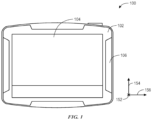
- FIG. 1 is a front view of the touchscreen display device 100 that may be used to monitor or regulate industrial automation devices or industrial automation equipment in an industrial automation system.
- the touchscreen display device 100 may be utilized to present information and/or control various operations associated with the industrial automation devices, the industrial automation equipment, the industrial system, or the like.
- certain embodiments of the touchscreen display device 100 are described herein with regard to monitoring or regulating industrial automation devices or industrial automation equipment in an industrial automation system, it should be understood that such embodiments are exemplary.
- the touchscreen display device 100 may be used in any residential system, industrial system, or other suitable system ( e . g ., any touch system or touchscreen system).
- the touchscreen display device 100 may be integrated in the body of an industrial automation device or the body of industrial automation equipment.
- industrial automation devices or industrial automation equipment may include controllers, input/output (I/O) modules, motor control centers, motors, valves, actuators, temperature elements, pressure sensors, contactors, starters, sensors, drives, relays, protection devices, switchgear, compressors, network switches ( e . g ., Ethernet switches, modular-managed, fixed-managed, service-router, industrial, unmanaged, etc.), data centers, conveyor sections, movers, and the like.
- the touchscreen display device 100 may be a stand-alone device, such as a tablet, a laptop, and the like.
- the industrial automation devices or the industrial automation equipment may also be related to mixers, machine conveyors, tanks, skids, specialized original equipment manufacturer machines, scanners, gauges, valves, flow meters, and the like.
- the touchscreen display device 100 may be utilized to modify and/or view the settings and operations associated with the industrial automation devices, the industrial automation equipment, or the industrial system.
- the touchscreen display device 100 may be used to display various images generated by an industrial control system, such as a graphical user interface (GUI) for operating the industrial control system.
- GUI graphical user interface
- the GUI may be characterized as a human-machine interface, a human-interface machine, or the like.
- the touchscreen display device 100 may include a bezel 102, a touchscreen 104, and a housing 106.
- the touchscreen display device 100 may have any suitable combination of components to facilitate the presentation of information or controls associated with the industrial automation equipment or the industrial system.
- the touchscreen display device 100 may have a power board, a logic board, a display adapter board, or the like.
- certain components of the touchscreen display device 100 may not be visible from the front.
- certain portions of the housing 106 of the touchscreen display device 100 may not be visible from the front.
- the bezel may facilitate supporting or securing the touchscreen 104 within the touchscreen display device 100.
- the bezel 102 may have a shape and a size that corresponds to the shape and the size of the touchscreen 104. That is, one or more physical dimensions (e . g ., length, width, or height) of the bezel 102 may correspond to one or more physical dimensions of the touchscreen 104 such that the touchscreen 104, or portion thereof, may be held or secured within the bezel 102.
- the bezel 102 and the touchscreen 104 illustrated in FIG. 1 are substantially rectangular, it should be understood that the bezel 102 and the touchscreen 104 may have any desired shape or size.
- the touchscreen 104 may detect a physical touch by a user or an operator of the touchscreen display device 100.
- the touchscreen 104 is a resistive touchscreen.
- the resistive touchscreen may include, for example, a top layer (e.g., a top polyester-coated layer or the like) with a transparent conductive coating on a bottom side of the top layer, a middle layer, and a bottom glass layer with a transparent conductive coating on the top side of the bottom glass layer.
- the top layer may flex in order to register the touch from the user or the operator.
- the touchscreen is a projected capacitive touchscreen or another suitable type of touchscreen.
- the touchscreen 104 may have a liquid crystal display (LCD), a light-emitting diode (LED) display, a combination LCD-LED display, an organic LED (OLED) display, a quantum dot LED (QLED) display, a plasma display, or the like.
- an overlay may be optically bonded to the top layer of the touchscreen 104 with an optical-grade adhesive.
- the optical-grade adhesive may include a silicon-based adhesive, an epoxy-based adhesive, a polyurethane-based adhesive, or any other suitable adhesive for eliminating an air gap between the overlay and the touchscreen 104 when bonded together.
- the overlay may be a polyester overlay.
- the area of the overlay may extend beyond the area of the top layer of the touchscreen 104.
- the housing 106 of the touchscreen display device 100 may encompass or support the bezel 102 and the touchscreen 104 within the touchscreen display device 100 after assembly.
- the housing 106 may also encompass or support other components associated with the touchscreen display device 100.
- such components may include a power board, a logic board, a display adapter board, or the like.
- the touchscreen display device 100 may utilize a protective material or a sacrificial material (i.e., "a deposited material") to coat at least an exterior portion of the touchscreen 104 to prevent or minimize passage of gases from the ambient environment into the body ( e . g ., middle layer) of the touchscreen 104.
- FIG. 2 illustrates a block diagram of a portion of the touchscreen 104 supported by the bezel 102 in the touchscreen display device 100.
- the touchscreen 104 may have a top layer 110 (e.g., a top polyester-coated layer), a middle layer 112 (e.g., a middle adhesive layer), and a bottom layer 114 (e.g., a glass layer).
- the touchscreen 104 may be a resistive touchscreen, a projected capacitive touchscreen, or any other suitable type of touchscreen.
- the top layer 110 may have a transparent conductive coating 130 and one or more printed traces of conductive material 131, and the bottom layer 114 may have a transparent conductive coating 132 and one or more printed traces of conductive material 133.
- the transparent conductive coating 130 or 132 may include indium tin oxide, graphene, silver, copper, or the like.
- the traces of printed conductive material 131 or 133 may include silver, copper, or the like.
- the top layer 110 has traces of a printed conductive material 131 disposed below the transparent conductive coating 130 in the middle layer 112, and the bottom layer 114 has traces of a printed conductive material 133 disposed atop the transparent conductive coating 132 in the middle layer 112.
- FIG. 2 shows traces of the printed conductive material 131 and 133 for the top layer 110 and the bottom layer 114, it should be understood that, in certain embodiments, such conductive material may be disposed on either the top layer 110 or the bottom layer 114, or both. Additionally, in certain embodiments, the top layer 110 may have a first transparent conductive coating 130 on a side facing or proximal to the bottom layer 114, or the bottom layer 114 may have a second transparent conductive coating 132 on a side facing or proximal to the top layer 110, or both (e.g., in a resistive touchscreen).
- the top layer 110 may be optically bonded to an overlay 122 with an optical-grade adhesive 124.
- the optical-grade adhesive 124 may include a silicon-based adhesive, an epoxy-based adhesive, a polyurethane-based adhesive, or any other suitable adhesive for minimizing an air gap between the overlay 122 and the top layer 110 of the touchscreen 104 when bonded together.
- the overlay 122 may be a polyester overlay.
- the area of the overlay 122 may extend beyond the area of the top layer 110 of the touchscreen 104 in the vertical direction 154, the lateral direction 156, or both.
- a protective material or a sacrificial material i.e., "a deposited material” 120
- a deposited material 120 may be utilized to coat at least an exterior portion of the touchscreen 104.
- the deposited material 120 may extend over the middle layer 112 and around a perimeter of the touchscreen top layer 110 such that the deposited material 120 forms a seal to prevent or minimize passage of gases from the ambient environment into the middle layer 112 from the environment of the touchscreen display device 100.
- the deposited material 120 may include a conformal coat material, such as an acrylic-based coat material, an epoxy-based coat material, a polyurethane-based coat material, a silicone-based coat material, a parylene-based coat material, a fluoropolymer-based coat material; a urethane; a caulk, such as a sacrificial copper-impregnated caulk and/or a sacrificial silver-impregnated caulk; or the like.
- a conformal coat material such as an acrylic-based coat material, an epoxy-based coat material, a polyurethane-based coat material, a silicone-based coat material, a parylene-based coat material, a fluoropolymer-based coat material; a urethane; a caulk, such as a sacrificial copper-impregnated caulk and/or a sacrificial silver-impregnated caulk; or the like.
- the deposited material 120 may extend from the overlay 122 to the bottom layer 114 in the longitudinal direction 152. That is, a length of the deposited material 120 may extend in the longitudinal direction 152 from at least a portion of the overlay 122, along the optical clear adhesive 124, along the top layer 110, along the first transparent conductive coating 130, along the middle layer 112, along the second transparent conductive coating 132, and at least a portion of the bottom layer 114.
- the length of the deposited material 120 may be any suitable length for sealing the touchscreen 104 from the environment of the touchscreen display device 102.
- the length of the deposited material 120 may extend in the longitudinal direction 152 from at least a portion of the optical clear adhesive 124 to at least a portion of the bottom layer 114, at least a portion of the top layer 110 to at least a portion of the bottom layer 114, or the like.
- the height of the deposited material 120 in the vertical direction 154 may be any suitable height or the width of the deposited material 120 in the lateral direction 156 may be any suitable width for sealing the interior of the touchscreen 112 and 118 from the environment of the touchscreen display device 104.
- the geometric profile (e.g., a cross-section) of the deposited material 120 is triangular-shaped.
- the geometric profile of the deposited material 120 may be any suitable shape for maintaining a seal between the interior of the touchscreen display device 112 and 118 (e.g., the middle layer 112) and the environment of the touchscreen display device.
- the geometric profile of the deposited material may be rectangular-shaped, square-shaped, circular-shaped, pentagonal-shaped, hexagonal-shaped, or the like.
- FIG. 2 shows the deposited material 120 on one side of the touchscreen 104
- the deposited material 120 may be utilized on more than one side of the touchscreen 104 to ensure that the middle layer 112 is sealed from the environment of the touchscreen display device 100. That is, the deposited material 120 may extend around the perimeter of the touchscreen 104, or a portion thereof, to ensure the formation of the seal between the middle layer 112 and the environment of the touchscreen display device 100.
- the illustrations of the touchscreen 104 in FIG. 2 is not to scale. That is, the respective size of each component of the touchscreen display device 100 may be any suitable size for the component, and the respective shape of each component of the touchscreen display device 100 may be any suitable shape for the component.
- FIG. 3 illustrates a flowchart of a method 200 for assembling the touchscreen 104 of the touchscreen display device 100.
- the method 200 is not limited to the depicted order, and instead, the method 200 may be performed in any suitable order.
- the top layer 110, the middle layer 112, and the bottom layer 114 are assembled together into the touchscreen 104.
- the touchscreen 104 may be assembled as a resistive touchscreen, a projected capacitive touchscreen, or any other suitable type of touchscreen.
- an overlay 122 may optionally optically bonded to the top layer 110 with an optical-grade adhesive 124.
- the optical-grade adhesive 124 may include a silicon-based adhesive, an epoxy-based adhesive, a polyurethane-based adhesive, or any other suitable adhesive for minimizing an air gap between the overlay 122 and the top layer 110 of the touchscreen 104 when bonded together.
- a protective material or a sacrificial material may be utilized to coat at least an exterior portion of the touchscreen 104.
- the deposited material 120 may extend over the middle layer 112 and around a perimeter of the touchscreen top layer 110 such that the deposited material 120 forms a seal to prevent or minimize passage of gases from the ambient environment into the middle layer 112 from the environment of the touchscreen display device 100.
- the deposited material 120 may include a conformal coat material, such as an acrylic-based coat material, an epoxy-based coat material, a polyurethane-based coat material, a silicone-based coat material, a parylene-based coat material, a fluoropolymer-based coat material; a urethane; a caulk, such as a sacrificial copper-impregnated caulk and/or a sacrificial silver-impregnated caulk; or the like.
- a conformal coat material such as an acrylic-based coat material, an epoxy-based coat material, a polyurethane-based coat material, a silicone-based coat material, a parylene-based coat material, a fluoropolymer-based coat material; a urethane; a caulk, such as a sacrificial copper-impregnated caulk and/or a sacrificial silver-impregnated caulk; or the like.
- a deposited material may form a seal between the body of the touchscreen (e . g ., a middle layer) and the exterior environment of the touchscreen display device.
- the deposited material may act as a sacrificial material to the gases in the ambient environment such that the corrosive gases interact with the deposited material rather than the material within the touchscreen that is susceptible to corrosion. Accordingly, by using the deposited material as a seal between the body of the touchscreen and the exterior environment of the touchscreen, the lifespan of the touchscreen display device may increase in industrial systems where corrosive gas exposure is likely.
- a touchscreen display device comprising:
- Embodiment 2 The touchscreen display device of embodiment 1, wherein the deposited material comprises a conformal coat material.
- Embodiment 3 The touchscreen display device of embodiment 2, wherein the conformal coat material comprises an acrylic-based material, an epoxy-based material, a polyurethane-based material, a silicone-based material, a parylene-based material, or a fluoropolyer-based material.
- Embodiment 4 The touchscreen display device of embodiment 1, wherein the deposited material comprises a caulk.
- Embodiment 5 The touchscreen display device of embodiment 4, wherein the caulk comprises a sacrificial copper-impregnated caulk or a sacrificial silver-impregnated caulk.
- Embodiment 6 The touchscreen display device of embodiment 1, wherein the overlay is optically bonded to the top layer of the touchscreen using an optical-grade adhesive.
- Embodiment 7 The touchscreen display device of embodiment 6, wherein the length of the deposited material extends from the at least the first portion of the overlay over the optical-grade adhesive to the top layer over the middle layer to the at least the second portion of the bottom layer.
- Embodiment 8 A touchscreen for a display device, comprising:
- Embodiment 9 The touchscreen of embodiment 8, wherein the deposited material comprises a conformal coat material.
- Embodiment 10 The touchscreen of embodiment 8, wherein the deposited material comprises a sacrificial caulk.
- Embodiment 11 The touchscreen of embodiment 8, comprising an overlay optically bonded to the top layer of the touchscreen.
- Embodiment 12 The touchscreen of embodiment 8, wherein the deposited material has a triangular-shaped geometric profile.
- Embodiment 13 The touchscreen of embodiment 8, wherein the touchscreen is configured to be integrated within a body of an industrial automation device.
- Embodiment 14 The touchscreen of embodiment 8, wherein the deposited material is impermeable to corrosive gas.
- Embodiment 15 A method, comprising:
- Embodiment 16 The method of embodiment 15, wherein the touchscreen is a resistive touchscreen.
- Embodiment 17 The method of embodiment 15, wherein the touchscreen is a projected capacitive touch screen.
- Embodiment 18 The method of embodiment 15, comprising optically bonding an overlay to the top layer of the touchscreen using an optical-grade adhesive.
- Embodiment 19 The method of embodiment 18, wherein the length of the deposited material extends from at least a third portion of the overlay over the optical-grade adhesive to the at least the first portion of the top layer over the middle layer to at least the second portion of the bottom layer.
- Embodiment 20 The method of embodiment 15, wherein the deposited material is impermeable to corrosive gas.
Landscapes
- Engineering & Computer Science (AREA)
- Physics & Mathematics (AREA)
- General Engineering & Computer Science (AREA)
- Theoretical Computer Science (AREA)
- General Physics & Mathematics (AREA)
- Human Computer Interaction (AREA)
- Nonlinear Science (AREA)
- Mathematical Physics (AREA)
- Chemical & Material Sciences (AREA)
- Crystallography & Structural Chemistry (AREA)
- Optics & Photonics (AREA)
- Position Input By Displaying (AREA)
Abstract
Description
- The disclosure generally relates to touchscreen display devices. More particular, embodiments of the present disclosure are related to assembling components of a touchscreen for a display device to prevent or minimize the passage of corrosive gas into the body of the touchscreen.
- An industrial automation system may include one or more touchscreen display devices to display information relating to monitoring and/or regulating industrial automation equipment in the industrial automation system. In certain types of industrial automation systems, a touchscreen display device may be exposed to corrosive gases that might be present in an environment of the industrial automation systems. Such corrosive gases may be the byproduct of an industrial process, may be used during the industrial process to achieve some purpose, or may be present in the environment surrounding the industrial automation system for some other reason. The corrosive gases may permeate the body of a touchscreen of the display device and negatively affect certain materials present within the body of the touchscreen, or otherwise reduce the lifespan or operability of the touchscreen. For instance, the touchscreen may contain certain functional circuit constructs made of materials, such as silver and copper, that are susceptible to corrosion should the functional circuit constructs come into contact with the corrosive gases. As such, it may be desirable to provide an improved touchscreen display device that prevents or minimizes the passage of corrosive gasses into the body of the touchscreen.
- This section is intended to introduce the reader to various aspects of art that may be related to various aspects of the present techniques, which are described and/or claimed below. This discussion is believed to be helpful in providing the reader with background information to facilitate a better understanding of the various aspects of the present disclosure. Accordingly, it should be understood that these statements are to be read in this light, and not as admissions of prior art.
- A summary of certain embodiments disclosed herein is set forth below. It should be understood that these aspects are presented merely to provide the reader with a brief summary of these certain embodiments and that these aspects are not intended to limit the scope of this disclosure. Indeed, this disclosure may encompass a variety of aspects that may not be set forth below.
- In one embodiment, a touchscreen display device may include a touchscreen disposed in a housing. The touchscreen includes a top layer, a middle layer, and a bottom layer. The touchscreen display device may also include an overlay optically bonded to the top layer of the touchscreen and a deposited material that extends around a perimeter of the touchscreen within the housing. A length of the deposited material may extend from at least a first portion of the overlay to at least a second portion of the bottom layer. The deposited material forms a seal over the middle layer between the touchscreen and an environment of the touchscreen display device.
- In another embodiment, a touchscreen for a display device includes a top layer, a bottom layer, and a middle layer between the top layer and the bottom layer. The touchscreen also includes a deposited material that extends around a perimeter of the touchscreen. A length of the deposited material has a length that extends from at least a first portion of the top layer to at least a second portion of the bottom layer. The deposited material may form a seal over the middle layer between the touchscreen and an environment of the display device.
- In yet another embodiment, a method includes assembling a touchscreen that includes a top layer, a bottom layer, and a middle layer between the top layer and the bottom layer; and applying a deposited material that extends around a perimeter of the touchscreen, wherein a length of the deposited material extends from at least a first portion of the top layer to at least a second portion of the bottom layer, wherein the deposited material forms a seal over the middle layer between the touchscreen and an environment of the touchscreen.
- These and other features, aspects, and advantages of the present invention will become better understood when the following detailed description is read with reference to the accompanying drawings in which like characters represent like parts throughout the drawings, wherein:
-
FIG. 1 is a front view of a touchscreen display device that may be utilized in an industrial automation system, in accordance with an embodiment; -
FIG. 2 is a block diagram of a portion of a touchscreen within the touchscreen display device shown inFIG. 1 , in accordance with an embodiment; and -
FIG. 3 is a flowchart of a method for assembling the touchscreen of the touchscreen display device utilizing a deposited material, in accordance with an embodiment. - One or more specific embodiments of the present disclosure will be described below. In an effort to provide a concise description of these embodiments, all features of an actual implementation may not be described in the specification. It should be appreciated that in the development of any such actual implementation, as in any engineering or design project, numerous implementation-specific decisions must be made to achieve the developers' specific goals, such as compliance with system-related and business-related constraints, which may vary from one implementation to another. Moreover, it should be appreciated that such a development effort might be complex and time consuming, but would nevertheless be a routine undertaking of design, fabrication, and manufacture for those of ordinary skill having the benefit of this disclosure.
- When introducing elements of various embodiments of the present disclosure, the articles "a," "an," "the," and "said" are intended to mean that there are one or more of the elements. The terms "comprising," "including," and "having" are intended to be inclusive and mean that there may be additional elements other than the listed elements. One or more specific embodiments of the present embodiments described herein will be described below. In an effort to provide a concise description of these embodiments, all features of an actual implementation may not be described in the specification. It should be appreciated that in the development of any such actual implementation, as in any engineering or design project, numerous implementation-specific decisions must be made to achieve the developers' specific goals, such as compliance with system-related and business-related constraints, which may vary from one implementation to another. Moreover, it should be appreciated that such a development effort might be complex and time consuming, but would nevertheless be a routine undertaking of design, fabrication, and manufacture for those of ordinary skill having the benefit of this disclosure.
- The present disclosure is directed to an improved touchscreen display device and an improved technique for assembling the touchscreen display device that may prevent or minimize the passage of gases (e.g., corrosive gases) from entering the body of a touchscreen of the touchscreen display device. As mentioned above, in certain types of industrial automation systems, corrosive gases may permeate the body of the touchscreen and negatively affect certain materials within the body of the touchscreen. For example, a resistive touchscreen may be constructed of several layers: a top layer with a transparent conductive coating on the bottom, a middle layer, and a bottom glass layer with a transparent conductive coating on the top. The transparent conductive coating on the top layer and the bottom glass layer may have traces of printed conductive material, such as silver or copper, which is susceptible to corrosion.
- In order to prevent or minimize passage of corrosive gases into the middle layer, the improved touchscreen display device and the improved technique for assembling the touchscreen display device may utilize a protective material or a sacrificial material (i.e., "a deposited material") to coat at least an exterior portion of the touchscreen. For instance, the deposited material may extend over the middle layer (e.g., from the top polyester-coated layer to the bottom glass layer) to seal the middle layer from the environment of the touchscreen display device. In certain embodiments, the deposited material may include a conformal coat material, such as an acrylic-based coat material, an epoxy-based coat material, a polyurethane-based coat material, a silicone-based coat material, a parylene-based coat material, a fluoropolymer-based coat material; a urethane; a caulk, such as a sacrificial copper-impregnated caulk and/or a sacrificial silver-impregnated caulk; or the like. By utilizing the deposited material to seal the middle layer, the integrity of the touchscreen may be maintained in a corrosive environment, thereby extending the lifespan of the touchscreen display device and improving its operability in the corrosive environment.
- Although certain embodiments of the disclosure are described with respect to components of a resistive touchscreen, it should be understood that such techniques may be used with any suitable type of touchscreen device to prevent or minimize passage of corrosive gases into the interior of the touchscreen device. For example, such techniques may be used to seal the body of a projected capacitive touchscreen from the environment of the projected capacitive touchscreen or any other suitable type of touchscreen device.
- To facilitate discussion of
FIGS. 1-3 , thetouchscreen display device 100 and its components may be described with reference to a longitudinal axis ordirection 152, a vertical axis ordirection 154, and a lateral axis ordirection 156. With the foregoing in mind,FIG. 1 is a front view of thetouchscreen display device 100 that may be used to monitor or regulate industrial automation devices or industrial automation equipment in an industrial automation system. For example, thetouchscreen display device 100 may be utilized to present information and/or control various operations associated with the industrial automation devices, the industrial automation equipment, the industrial system, or the like. Although certain embodiments of thetouchscreen display device 100 are described herein with regard to monitoring or regulating industrial automation devices or industrial automation equipment in an industrial automation system, it should be understood that such embodiments are exemplary. As such, thetouchscreen display device 100 may be used in any residential system, industrial system, or other suitable system (e.g., any touch system or touchscreen system). - In some embodiments, the
touchscreen display device 100 may be integrated in the body of an industrial automation device or the body of industrial automation equipment. For example, such industrial automation devices or industrial automation equipment may include controllers, input/output (I/O) modules, motor control centers, motors, valves, actuators, temperature elements, pressure sensors, contactors, starters, sensors, drives, relays, protection devices, switchgear, compressors, network switches (e.g., Ethernet switches, modular-managed, fixed-managed, service-router, industrial, unmanaged, etc.), data centers, conveyor sections, movers, and the like. In other embodiments, thetouchscreen display device 100 may be a stand-alone device, such as a tablet, a laptop, and the like. The industrial automation devices or the industrial automation equipment may also be related to mixers, machine conveyors, tanks, skids, specialized original equipment manufacturer machines, scanners, gauges, valves, flow meters, and the like. - The
touchscreen display device 100 may be utilized to modify and/or view the settings and operations associated with the industrial automation devices, the industrial automation equipment, or the industrial system. Thetouchscreen display device 100 may be used to display various images generated by an industrial control system, such as a graphical user interface (GUI) for operating the industrial control system. In some embodiments, the GUI may be characterized as a human-machine interface, a human-interface machine, or the like. - As illustrated in
FIG. 1 , thetouchscreen display device 100 may include abezel 102, atouchscreen 104, and ahousing 106. However, it should be understood that thetouchscreen display device 100 may have any suitable combination of components to facilitate the presentation of information or controls associated with the industrial automation equipment or the industrial system. For example, thetouchscreen display device 100 may have a power board, a logic board, a display adapter board, or the like. In some embodiments, certain components of thetouchscreen display device 100 may not be visible from the front. In some embodiments, certain portions of thehousing 106 of thetouchscreen display device 100 may not be visible from the front. - The bezel may facilitate supporting or securing the
touchscreen 104 within thetouchscreen display device 100. Generally, thebezel 102 may have a shape and a size that corresponds to the shape and the size of thetouchscreen 104. That is, one or more physical dimensions (e.g., length, width, or height) of thebezel 102 may correspond to one or more physical dimensions of thetouchscreen 104 such that thetouchscreen 104, or portion thereof, may be held or secured within thebezel 102. Although thebezel 102 and thetouchscreen 104 illustrated inFIG. 1 are substantially rectangular, it should be understood that thebezel 102 and thetouchscreen 104 may have any desired shape or size. - The
touchscreen 104 may detect a physical touch by a user or an operator of thetouchscreen display device 100. In some embodiments, thetouchscreen 104 is a resistive touchscreen. For example, the resistive touchscreen may include, for example, a top layer (e.g., a top polyester-coated layer or the like) with a transparent conductive coating on a bottom side of the top layer, a middle layer, and a bottom glass layer with a transparent conductive coating on the top side of the bottom glass layer. When the user or the operator touches the top layer of thetouchscreen 104, the top layer may flex in order to register the touch from the user or the operator. In other embodiments, the touchscreen is a projected capacitive touchscreen or another suitable type of touchscreen. - The
touchscreen 104 may have a liquid crystal display (LCD), a light-emitting diode (LED) display, a combination LCD-LED display, an organic LED (OLED) display, a quantum dot LED (QLED) display, a plasma display, or the like. In some embodiments, an overlay may be optically bonded to the top layer of thetouchscreen 104 with an optical-grade adhesive. For example, the optical-grade adhesive may include a silicon-based adhesive, an epoxy-based adhesive, a polyurethane-based adhesive, or any other suitable adhesive for eliminating an air gap between the overlay and thetouchscreen 104 when bonded together. In certain embodiments, the overlay may be a polyester overlay. In certain embodiments, the area of the overlay may extend beyond the area of the top layer of thetouchscreen 104. - The
housing 106 of thetouchscreen display device 100 may encompass or support thebezel 102 and thetouchscreen 104 within thetouchscreen display device 100 after assembly. Thehousing 106 may also encompass or support other components associated with thetouchscreen display device 100. For example, such components may include a power board, a logic board, a display adapter board, or the like. - As described above, the
touchscreen display device 100 may utilize a protective material or a sacrificial material (i.e., "a deposited material") to coat at least an exterior portion of thetouchscreen 104 to prevent or minimize passage of gases from the ambient environment into the body (e.g., middle layer) of thetouchscreen 104. With the foregoing in mind,FIG. 2 illustrates a block diagram of a portion of thetouchscreen 104 supported by thebezel 102 in thetouchscreen display device 100. Thetouchscreen 104 may have a top layer 110 (e.g., a top polyester-coated layer), a middle layer 112 (e.g., a middle adhesive layer), and a bottom layer 114 (e.g., a glass layer). In certain embodiments, thetouchscreen 104 may be a resistive touchscreen, a projected capacitive touchscreen, or any other suitable type of touchscreen. - The
top layer 110 may have a transparentconductive coating 130 and one or more printed traces ofconductive material 131, and thebottom layer 114 may have a transparentconductive coating 132 and one or more printed traces ofconductive material 133. In certain embodiments, the transparentconductive coating conductive material FIG. 2 , thetop layer 110 has traces of a printedconductive material 131 disposed below the transparentconductive coating 130 in themiddle layer 112, and thebottom layer 114 has traces of a printedconductive material 133 disposed atop the transparentconductive coating 132 in themiddle layer 112. AlthoughFIG. 2 shows traces of the printedconductive material top layer 110 and thebottom layer 114, it should be understood that, in certain embodiments, such conductive material may be disposed on either thetop layer 110 or thebottom layer 114, or both. Additionally, in certain embodiments, thetop layer 110 may have a first transparentconductive coating 130 on a side facing or proximal to thebottom layer 114, or thebottom layer 114 may have a second transparentconductive coating 132 on a side facing or proximal to thetop layer 110, or both (e.g., in a resistive touchscreen). - In certain embodiments, the
top layer 110 may be optically bonded to anoverlay 122 with an optical-grade adhesive 124. As described above, the optical-grade adhesive 124 may include a silicon-based adhesive, an epoxy-based adhesive, a polyurethane-based adhesive, or any other suitable adhesive for minimizing an air gap between theoverlay 122 and thetop layer 110 of thetouchscreen 104 when bonded together. In some embodiments, theoverlay 122 may be a polyester overlay. In some embodiments, the area of theoverlay 122 may extend beyond the area of thetop layer 110 of thetouchscreen 104 in thevertical direction 154, thelateral direction 156, or both. - After the
touchscreen 104 has been assembled together, a protective material or a sacrificial material (i.e., "a deposited material" 120) may be utilized to coat at least an exterior portion of thetouchscreen 104. For instance, the depositedmaterial 120 may extend over themiddle layer 112 and around a perimeter of thetouchscreen top layer 110 such that the depositedmaterial 120 forms a seal to prevent or minimize passage of gases from the ambient environment into themiddle layer 112 from the environment of thetouchscreen display device 100. In certain embodiments, the depositedmaterial 120 may include a conformal coat material, such as an acrylic-based coat material, an epoxy-based coat material, a polyurethane-based coat material, a silicone-based coat material, a parylene-based coat material, a fluoropolymer-based coat material; a urethane; a caulk, such as a sacrificial copper-impregnated caulk and/or a sacrificial silver-impregnated caulk; or the like. - As illustrated in
FIG. 2 , the depositedmaterial 120 may extend from theoverlay 122 to thebottom layer 114 in thelongitudinal direction 152. That is, a length of the depositedmaterial 120 may extend in thelongitudinal direction 152 from at least a portion of theoverlay 122, along the opticalclear adhesive 124, along thetop layer 110, along the first transparentconductive coating 130, along themiddle layer 112, along the second transparentconductive coating 132, and at least a portion of thebottom layer 114. However, it should be understood that the length of the depositedmaterial 120 may be any suitable length for sealing thetouchscreen 104 from the environment of thetouchscreen display device 102. For example, the length of the depositedmaterial 120 may extend in thelongitudinal direction 152 from at least a portion of the opticalclear adhesive 124 to at least a portion of thebottom layer 114, at least a portion of thetop layer 110 to at least a portion of thebottom layer 114, or the like. Additionally, the height of the depositedmaterial 120 in thevertical direction 154 may be any suitable height or the width of the depositedmaterial 120 in thelateral direction 156 may be any suitable width for sealing the interior of thetouchscreen touchscreen display device 104. - Additionally, as illustrated in
FIG. 2 , the geometric profile (e.g., a cross-section) of the depositedmaterial 120 is triangular-shaped. However, it should be understood that the geometric profile of the depositedmaterial 120 may be any suitable shape for maintaining a seal between the interior of thetouchscreen display device 112 and 118 (e.g., the middle layer 112) and the environment of the touchscreen display device. For instance, the geometric profile of the deposited material may be rectangular-shaped, square-shaped, circular-shaped, pentagonal-shaped, hexagonal-shaped, or the like. - Although
FIG. 2 shows the depositedmaterial 120 on one side of thetouchscreen 104, it should be understood that the depositedmaterial 120 may be utilized on more than one side of thetouchscreen 104 to ensure that themiddle layer 112 is sealed from the environment of thetouchscreen display device 100. That is, the depositedmaterial 120 may extend around the perimeter of thetouchscreen 104, or a portion thereof, to ensure the formation of the seal between themiddle layer 112 and the environment of thetouchscreen display device 100. Additionally, it should be understood that the illustrations of thetouchscreen 104 inFIG. 2 is not to scale. That is, the respective size of each component of thetouchscreen display device 100 may be any suitable size for the component, and the respective shape of each component of thetouchscreen display device 100 may be any suitable shape for the component. - With the foregoing in mind,
FIG. 3 illustrates a flowchart of amethod 200 for assembling thetouchscreen 104 of thetouchscreen display device 100. Although the following description of themethod 200 is described in a particular order, it should be noted that themethod 200 is not limited to the depicted order, and instead, themethod 200 may be performed in any suitable order. Referring to FIG. 4, atblock 202, thetop layer 110, themiddle layer 112, and thebottom layer 114 are assembled together into thetouchscreen 104. In certain embodiments, thetouchscreen 104 may be assembled as a resistive touchscreen, a projected capacitive touchscreen, or any other suitable type of touchscreen. - After the
touchscreen 104 has been assembled, atblock 204, anoverlay 122 may optionally optically bonded to thetop layer 110 with an optical-grade adhesive 124. As described above, the optical-grade adhesive 124 may include a silicon-based adhesive, an epoxy-based adhesive, a polyurethane-based adhesive, or any other suitable adhesive for minimizing an air gap between theoverlay 122 and thetop layer 110 of thetouchscreen 104 when bonded together. - At
block 206, a protective material or a sacrificial material (i.e., "a deposited material" 120) may be utilized to coat at least an exterior portion of thetouchscreen 104. For instance, the depositedmaterial 120 may extend over themiddle layer 112 and around a perimeter of thetouchscreen top layer 110 such that the depositedmaterial 120 forms a seal to prevent or minimize passage of gases from the ambient environment into themiddle layer 112 from the environment of thetouchscreen display device 100. In certain embodiments, the depositedmaterial 120 may include a conformal coat material, such as an acrylic-based coat material, an epoxy-based coat material, a polyurethane-based coat material, a silicone-based coat material, a parylene-based coat material, a fluoropolymer-based coat material; a urethane; a caulk, such as a sacrificial copper-impregnated caulk and/or a sacrificial silver-impregnated caulk; or the like. - Technical effects of the present disclosure include technique for providing an improved touchscreen display device and an improved technique for assembling the touchscreen display device that may prevent or minimize the passage of gases (e.g., corrosive gases) from the ambient environment into the body of a touchscreen of the touchscreen display device. For instance, a deposited material may form a seal between the body of the touchscreen (e.g., a middle layer) and the exterior environment of the touchscreen display device. In this way, corrosive gases may be prevented from entering the body of the touchscreen via the middle layer. Additionally, or alternatively, the deposited material may act as a sacrificial material to the gases in the ambient environment such that the corrosive gases interact with the deposited material rather than the material within the touchscreen that is susceptible to corrosion. Accordingly, by using the deposited material as a seal between the body of the touchscreen and the exterior environment of the touchscreen, the lifespan of the touchscreen display device may increase in industrial systems where corrosive gas exposure is likely.
- The techniques presented and claimed herein are referenced and applied to material objects and concrete examples of a practical nature that demonstrably improve the present technical field and, as such, are not abstract, intangible or purely theoretical. Further, if any claims appended to the end of this specification contain one or more elements designated as "means for [perform]ing [a function]..." or "step for [perform]ing [a function]...", it is intended that such elements are to be interpreted under 35 U.S.C. 112(f). However, for any claims containing elements designated in any other manner, it is intended that such elements are not to be interpreted under 35 U.S.C. 112(f).
- While only certain features of the invention have been illustrated and described herein, many modifications and changes will occur to those skilled in the art. It is, therefore, to be understood that the appended claims are intended to cover all such modifications and changes as fall within the true spirit of the invention.
- Embodiment 1. A touchscreen display device, comprising:
- a touchscreen disposed in a housing, wherein the touchscreen includes a top layer, a middle layer, and a bottom layer;
- an overlay optically bonded to the top layer of the touchscreen; and
- a deposited material that extends around a perimeter of the touchscreen within the housing, wherein a length of the deposited material extends from at least a first portion of the overlay to at least a second portion of the bottom layer, wherein the deposited material is configured to form a seal over the middle layer between the touchscreen and an environment of the touchscreen display device.
- Embodiment 2. The touchscreen display device of embodiment 1, wherein the deposited material comprises a conformal coat material.
- Embodiment 3. The touchscreen display device of embodiment 2, wherein the conformal coat material comprises an acrylic-based material, an epoxy-based material, a polyurethane-based material, a silicone-based material, a parylene-based material, or a fluoropolyer-based material.
- Embodiment 4. The touchscreen display device of embodiment 1, wherein the deposited material comprises a caulk.
- Embodiment 5. The touchscreen display device of embodiment 4, wherein the caulk comprises a sacrificial copper-impregnated caulk or a sacrificial silver-impregnated caulk.
- Embodiment 6. The touchscreen display device of embodiment 1, wherein the overlay is optically bonded to the top layer of the touchscreen using an optical-grade adhesive.
- Embodiment 7. The touchscreen display device of embodiment 6, wherein the length of the deposited material extends from the at least the first portion of the overlay over the optical-grade adhesive to the top layer over the middle layer to the at least the second portion of the bottom layer.
- Embodiment 8. A touchscreen for a display device, comprising:
- a top layer;
- a bottom layer;
- a middle layer between the top layer and the bottom layer; and
- a deposited material that extends around a perimeter of the touchscreen, wherein a length of the deposited material extends from at least a first portion of the top layer to at least a second portion of the bottom layer, and wherein the deposited material is configured to form a seal over the middle layer between the touchscreen and an environment of the display device.
- Embodiment 9. The touchscreen of embodiment 8, wherein the deposited material comprises a conformal coat material.
- Embodiment 10. The touchscreen of embodiment 8, wherein the deposited material comprises a sacrificial caulk.
- Embodiment 11. The touchscreen of embodiment 8, comprising an overlay optically bonded to the top layer of the touchscreen.
- Embodiment 12. The touchscreen of embodiment 8, wherein the deposited material has a triangular-shaped geometric profile.
- Embodiment 13. The touchscreen of embodiment 8, wherein the touchscreen is configured to be integrated within a body of an industrial automation device.
- Embodiment 14. The touchscreen of embodiment 8, wherein the deposited material is impermeable to corrosive gas.
- Embodiment 15. A method, comprising:
- assembling a touchscreen that includes a top layer, a bottom layer, and a middle layer between the top layer and the bottom layer; and
- applying a deposited material that extends around a perimeter of the touchscreen, wherein a length of the deposited material extends from at least a first portion of the top layer to at least a second portion of the bottom layer, wherein the deposited material is configured to form a seal over the middle layer between the touchscreen and an environment of the touchscreen.
- Embodiment 16. The method of embodiment 15, wherein the touchscreen is a resistive touchscreen.
- Embodiment 17. The method of embodiment 15, wherein the touchscreen is a projected capacitive touch screen.
- Embodiment 18. The method of embodiment 15, comprising optically bonding an overlay to the top layer of the touchscreen using an optical-grade adhesive.
- Embodiment 19. The method of embodiment 18, wherein the length of the deposited material extends from at least a third portion of the overlay over the optical-grade adhesive to the at least the first portion of the top layer over the middle layer to at least the second portion of the bottom layer.
- Embodiment 20. The method of embodiment 15, wherein the deposited material is impermeable to corrosive gas.
Claims (15)
- A touchscreen display device, comprising:a touchscreen disposed in a housing, wherein the touchscreen includes a top layer, a middle layer, and a bottom layer;an overlay optically bonded to the top layer of the touchscreen; anda deposited material that extends around a perimeter of the touchscreen within the housing, wherein a length of the deposited material extends from at least a first portion of the overlay to at least a second portion of the bottom layer, wherein the deposited material is configured to form a seal over the middle layer between the touchscreen and an environment of the touchscreen display device.
- The touchscreen display device of claim 1, wherein the deposited material comprises a conformal coat material.
- The touchscreen display device of claim 2, wherein the conformal coat material comprises an acrylic-based material, an epoxy-based material, a polyurethane-based material, a silicone-based material, a parylene-based material, or a fluoropolyer-based material.
- The touchscreen display device of claim 1, wherein the deposited material comprises a caulk.
- The touchscreen display device of claim 4, wherein the caulk comprises a sacrificial copper-impregnated caulk or a sacrificial silver-impregnated caulk.
- The touchscreen display device of claim 1, wherein the overlay is optically bonded to the top layer of the touchscreen using an optical-grade adhesive.
- The touchscreen display device of claim 6, wherein the length of the deposited material extends from the at least the first portion of the overlay over the optical-grade adhesive to the top layer over the middle layer to the at least the second portion of the bottom layer.
- A touchscreen for a display device, comprising:a top layer;a bottom layer;a middle layer between the top layer and the bottom layer; anda deposited material that extends around a perimeter of the touchscreen, wherein a length of the deposited material extends from at least a first portion of the top layer to at least a second portion of the bottom layer, and wherein the deposited material is configured to form a seal over the middle layer between the touchscreen and an environment of the display device.
- The touchscreen of claim 8, wherein:the deposited material has a triangular-shaped geometric profile; and/orthe deposited material is impermeable to corrosive gas; and/orthe touchscreen is configured to be integrated within a body of an industrial automation device.
- The touchscreen of claim 8, wherein:the deposited material comprises a conformal coat material; orthe deposited material comprises a sacrificial caulk.
- The touchscreen of one of claims 8 to 10, comprising an overlay optically bonded to the top layer of the touchscreen.
- A method, comprising:assembling a touchscreen that includes a top layer, a bottom layer, and a middle layer between the top layer and the bottom layer; andapplying a deposited material that extends around a perimeter of the touchscreen, whereina length of the deposited material extends from at least a first portion of the top layer to at least a second portion of the bottom layer, wherein the deposited material is configured to form a seal over the middle layer between the touchscreen and an environment of the touchscreen.
- The method of claim 12, wherein:the touchscreen is a resistive touchscreen; orthe touchscreen is a projected capacitive touch screen.
- The method of claim 12 or 13, comprising optically bonding an overlay to the top layer of the touchscreen using an optical-grade adhesive, wherein the length of the deposited material extends from at least a third portion of the overlay over the optical-grade adhesive to the at least the first portion of the top layer over the middle layer to at least the second portion of the bottom layer.
- The method of one of claims 12 to 14, wherein the deposited material is impermeable to corrosive gas.
Applications Claiming Priority (1)
| Application Number | Priority Date | Filing Date | Title |
|---|---|---|---|
| US17/400,461 US11520442B1 (en) | 2021-08-12 | 2021-08-12 | Industrial automation display device with touchscreen |
Publications (1)
| Publication Number | Publication Date |
|---|---|
| EP4134795A1 true EP4134795A1 (en) | 2023-02-15 |
Family
ID=83193174
Family Applications (1)
| Application Number | Title | Priority Date | Filing Date |
|---|---|---|---|
| EP22189176.5A Pending EP4134795A1 (en) | 2021-08-12 | 2022-08-08 | Industrial automation display device with touchscreen |
Country Status (3)
| Country | Link |
|---|---|
| US (1) | US11520442B1 (en) |
| EP (1) | EP4134795A1 (en) |
| CN (1) | CN115705113A (en) |
Citations (2)
| Publication number | Priority date | Publication date | Assignee | Title |
|---|---|---|---|---|
| WO2017197522A1 (en) * | 2016-05-20 | 2017-11-23 | 1004335 Ontario Inc. C.O.B. As A D Metro | Touch sensor regulator device and method |
| US20200272255A1 (en) * | 2019-02-22 | 2020-08-27 | Qualcomm Incorporated | Stylus-tracking piezoelectric sensor |
Family Cites Families (5)
| Publication number | Priority date | Publication date | Assignee | Title |
|---|---|---|---|---|
| US5017736A (en) * | 1988-11-22 | 1991-05-21 | Magneshield Technologies, Inc. | Magnetically shielded door for use with shielded enclosures |
| EP0600570A1 (en) | 1992-11-30 | 1994-06-08 | Dynapro Thin Film Products Inc. | Touch switch with coating for inhibiting increased contact resistance |
| EP2056186A1 (en) * | 2007-10-26 | 2009-05-06 | Research In Motion Limited | Touch screen and electronic device |
| US8907871B2 (en) * | 2012-03-15 | 2014-12-09 | Corning Incorporated | Touch screen assemblies for electronic devices |
| JP6529431B2 (en) * | 2015-12-24 | 2019-06-12 | 株式会社フジクラ | Optical element package |
-
2021
- 2021-08-12 US US17/400,461 patent/US11520442B1/en active Active
-
2022
- 2022-08-08 EP EP22189176.5A patent/EP4134795A1/en active Pending
- 2022-08-10 CN CN202210955073.0A patent/CN115705113A/en active Pending
Patent Citations (2)
| Publication number | Priority date | Publication date | Assignee | Title |
|---|---|---|---|---|
| WO2017197522A1 (en) * | 2016-05-20 | 2017-11-23 | 1004335 Ontario Inc. C.O.B. As A D Metro | Touch sensor regulator device and method |
| US20200272255A1 (en) * | 2019-02-22 | 2020-08-27 | Qualcomm Incorporated | Stylus-tracking piezoelectric sensor |
Also Published As
| Publication number | Publication date |
|---|---|
| US11520442B1 (en) | 2022-12-06 |
| CN115705113A (en) | 2023-02-17 |
Similar Documents
| Publication | Publication Date | Title |
|---|---|---|
| US9291842B2 (en) | Display device, electronic apparatus, and method for manufacturing display device | |
| JP5069795B2 (en) | Apparatus and method for transporting weak impact glass plate in ultra clean room | |
| US10021226B2 (en) | Display cover mounting | |
| CN101263541B (en) | Display system for an industrial automation device | |
| US20150227201A1 (en) | Tactile sensation providing device | |
| US11211586B2 (en) | Flexible display device including window substrate, and manufacturing method thereof | |
| US9734677B2 (en) | Tactile sensation providing device | |
| US9910518B2 (en) | Transparency augmented industrial automation display | |
| JP6010055B2 (en) | Software rotatable display | |
| CN101673020A (en) | Electrophoretic display device, a manufacturing method for an electrophoretic display device, and a wristwatch | |
| US10585518B2 (en) | Display module support | |
| US11520442B1 (en) | Industrial automation display device with touchscreen | |
| Quint et al. | A system architecture for assistance in manual tasks | |
| JP2013052774A (en) | In-vehicle display device | |
| JP2010146418A (en) | Touch panel corresponding to narrow frame lcd | |
| EP2963527B1 (en) | Tactile sense presentation device | |
| JP2006163742A (en) | Display device with touch panel and manufacturing method thereof | |
| CN1677301A (en) | Manual operating unit for robot | |
| CN106547130A (en) | Touch control display | |
| EP4130859B1 (en) | Display device | |
| JP2013184283A (en) | Work cell control device and system for constructing control program for the control device | |
| JP2016076136A (en) | Touch panel with pressure sensor and manufacturing method of the same, and display device with touch panel | |
| JP2016009371A (en) | Touch panel, fixing structure of front face design sheet, and display device with touch panel | |
| JP4650012B2 (en) | Protective case mounted with electronic paper with input / output device and management system using the same | |
| KR101666804B1 (en) | Apparatus for etching |
Legal Events
| Date | Code | Title | Description |
|---|---|---|---|
| PUAI | Public reference made under article 153(3) epc to a published international application that has entered the european phase |
Free format text: ORIGINAL CODE: 0009012 |
|
| STAA | Information on the status of an ep patent application or granted ep patent |
Free format text: STATUS: THE APPLICATION HAS BEEN PUBLISHED |
|
| AK | Designated contracting states |
Kind code of ref document: A1 Designated state(s): AL AT BE BG CH CY CZ DE DK EE ES FI FR GB GR HR HU IE IS IT LI LT LU LV MC MK MT NL NO PL PT RO RS SE SI SK SM TR |
|
| STAA | Information on the status of an ep patent application or granted ep patent |
Free format text: STATUS: REQUEST FOR EXAMINATION WAS MADE |
|
| 17P | Request for examination filed |
Effective date: 20230726 |
|
| RBV | Designated contracting states (corrected) |
Designated state(s): AL AT BE BG CH CY CZ DE DK EE ES FI FR GB GR HR HU IE IS IT LI LT LU LV MC MK MT NL NO PL PT RO RS SE SI SK SM TR |
|
| STAA | Information on the status of an ep patent application or granted ep patent |
Free format text: STATUS: EXAMINATION IS IN PROGRESS |
|
| 17Q | First examination report despatched |
Effective date: 20260402 |