EP4134725B1 - Lens-free microscopic imaging system and method, and biochemical substance detection system and method - Google Patents
Lens-free microscopic imaging system and method, and biochemical substance detection system and method Download PDFInfo
- Publication number
- EP4134725B1 EP4134725B1 EP20930394.0A EP20930394A EP4134725B1 EP 4134725 B1 EP4134725 B1 EP 4134725B1 EP 20930394 A EP20930394 A EP 20930394A EP 4134725 B1 EP4134725 B1 EP 4134725B1
- Authority
- EP
- European Patent Office
- Prior art keywords
- microbeads
- lens
- image sensor
- microbead
- light source
- Prior art date
- Legal status (The legal status is an assumption and is not a legal conclusion. Google has not performed a legal analysis and makes no representation as to the accuracy of the status listed.)
- Active
Links
Images



Classifications
-
- G—PHYSICS
- G02—OPTICS
- G02B—OPTICAL ELEMENTS, SYSTEMS OR APPARATUS
- G02B21/00—Microscopes
- G02B21/36—Microscopes arranged for photographic purposes or projection purposes or digital imaging or video purposes including associated control and data processing arrangements
-
- G—PHYSICS
- G02—OPTICS
- G02B—OPTICAL ELEMENTS, SYSTEMS OR APPARATUS
- G02B21/00—Microscopes
- G02B21/36—Microscopes arranged for photographic purposes or projection purposes or digital imaging or video purposes including associated control and data processing arrangements
- G02B21/361—Optical details, e.g. image relay to the camera or image sensor
-
- G—PHYSICS
- G02—OPTICS
- G02B—OPTICAL ELEMENTS, SYSTEMS OR APPARATUS
- G02B21/00—Microscopes
- G02B21/36—Microscopes arranged for photographic purposes or projection purposes or digital imaging or video purposes including associated control and data processing arrangements
- G02B21/365—Control or image processing arrangements for digital or video microscopes
- G02B21/367—Control or image processing arrangements for digital or video microscopes providing an output produced by processing a plurality of individual source images, e.g. image tiling, montage, composite images, depth sectioning, image comparison
-
- G—PHYSICS
- G03—PHOTOGRAPHY; CINEMATOGRAPHY; ANALOGOUS TECHNIQUES USING WAVES OTHER THAN OPTICAL WAVES; ELECTROGRAPHY; HOLOGRAPHY
- G03H—HOLOGRAPHIC PROCESSES OR APPARATUS
- G03H1/00—Holographic processes or apparatus using light, infrared or ultraviolet waves for obtaining holograms or for obtaining an image from them; Details peculiar thereto
- G03H1/04—Processes or apparatus for producing holograms
- G03H1/0443—Digital holography, i.e. recording holograms with digital recording means
-
- G—PHYSICS
- G02—OPTICS
- G02B—OPTICAL ELEMENTS, SYSTEMS OR APPARATUS
- G02B5/00—Optical elements other than lenses
- G02B5/20—Filters
- G02B5/28—Interference filters
-
- G—PHYSICS
- G03—PHOTOGRAPHY; CINEMATOGRAPHY; ANALOGOUS TECHNIQUES USING WAVES OTHER THAN OPTICAL WAVES; ELECTROGRAPHY; HOLOGRAPHY
- G03H—HOLOGRAPHIC PROCESSES OR APPARATUS
- G03H1/00—Holographic processes or apparatus using light, infrared or ultraviolet waves for obtaining holograms or for obtaining an image from them; Details peculiar thereto
- G03H1/0005—Adaptation of holography to specific applications
- G03H2001/005—Adaptation of holography to specific applications in microscopy, e.g. digital holographic microscope [DHM]
Definitions
- the subject matter relates to biological detection, and more particularly, to a lens-free microscopic imaging system and method, and a biochemical substance detection system and method.
- a lot of assays for complex samples of macromolecular usually include two steps.
- molecules that can capture specific target macromolecules are attached to a surface of solid phase.
- Such attached molecules can capture the target macromolecules from a complex sample in various ways such as hybridization (e.g., in assays based on DNA, RNA) or interactions between antigens and antibodies (in immunoassays).
- molecules required for the detection hereinafter, “detection molecules” are incubated with and bonded to a compound of the capture molecules and the target, thereby emitting signals such as fluorescent or electromagnetic signals.
- the target is then quantified based on an intensity of the signals.
- Multiplex detection can be carried out by a variety of capture reagents that are specific for different target macromolecules.
- each type of capture reagent is attached to a predetermined position on the chip.
- Multiple targets in the complex sample are quantified by measuring the signal of the detection molecule at each position of the corresponding type of capture reagent.
- particles or microbeads are suspended in a solution required for the detection. Such particles or microbeads include identification elements that can be embedded, printed, or otherwise generated by one or more elements of the particles or microbeads.
- Each type of capture reagent is fixed to particles having a same identity number, and the signal emitted by the detection molecules on the particles having a specific identity number can reflect the amount of the corresponding target.
- the particles or microbeads can be identified, so that the signal from the molecules captured by the capture reagent is associated with the identity number to realize multiplex detection.
- the existing microscope can obtain clear images of the microbeads/magnetic beads and images of corresponding signals (such as fluorescent signals).
- signals such as fluorescent signals.
- the existing optical microscope also needs to perform a lens focusing process, which is not only time-consuming and laborious, but also difficult to find a focus plane.
- An optical lens system and a slider for moving the field of view result in the detecting system being high cost and not portable.
- D1 SASAGAWA KIYOTAKA ET AL: “Dual-mode lensless imaging device for digital enzyme linked immunosorbent assay”
- D2 Roy Mohendra ET AL: "A simple and low-cost device performing blood cell counting based on lens-free shadow imaging technique”
- D3 CN 101809444A
- D4 Qingshan Wei ET AL: "On-Chip Cytometry using Plasmonic Nanoparticle Enhanced Lensfree Holography ").
- the present disclosure provides a lens-free microscopic imaging system for imaging microbeads with pattern codes.
- the lens-free microscopic imaging system includes an illumination system and an imaging system.
- the illumination system includes an illumination light source and an excitation light source.
- the imaging system includes an image sensor.
- the illumination light source is configured to emit illumination light to irradiate the microbeads, causing the irradiated microbeads to be imaged on the image sensor.
- the excitation light source is configured to emit excitation light to excite the microbeads to generate specific signals
- the image sensor is configured to collect images of the microbeads and of the specific signals.
- the illumination light irradiates the microbeads, causing the images of the irradiated microbeads to be projected on the image sensor.
- the illumination light further forms interference fringes on the image sensor, and the interference fringes are collected by the image sensor.
- the illumination light source is a monochrome light source.
- a pinhole is arranged on an optical path from the illumination light source to the microbeads.
- the illumination light source is configured to emit the illumination light from a first orientation to a second orientation to irradiate the microbeads.
- the excitation light source is configured to emit the excitation light from the first orientation to the second orientation.
- the illumination system further includes a total reflection device.
- the total reflection device includes a total reflection surface, and the total reflection surface is configured to reflect the excitation light emitted by the excitation light source to the microbeads.
- the total reflection surface is arranged in the second orientation, and is configured to reflect the excitation light from the second orientation to the first orientation.
- the illumination light source is configured to emit the illumination light from a first orientation to a second orientation to irradiate the microbeads
- the excitation light source is configured to emit the excitation light from the second orientation to the first orientation
- a filtering device is further included, which is in front of or on the image sensor.
- the present disclosure provides a lens-free microscopic imaging method for imaging microbeads with pattern codes.
- the microbeads are configured to capture specific biochemical substances.
- the lens-free microscopic imaging method including:
- the illumination light irradiates the microbeads, causing the irradiated microbeads to be projected on the image sensor.
- the illumination light source 111 is powered on, which irradiates the microbeads 15 from the first orientation to the second orientation, and the irradiated microbeads 15 are projected onto the image sensor 113.
- the excitation light source 112 is powered on, which emits the excitation light from the first orientation to the second orientation to irradiate the microbeads 15, causing the microbeads 15 to emit the fluorescent signals toward the image sensor 113.
- the image sensor 113 collects the projections and the fluorescent signals of the microbeads 15, and generates the images of the microbeads 15 and the fluorescent signals. The images are output to the recognition and detection device 13.
Landscapes
- Physics & Mathematics (AREA)
- Engineering & Computer Science (AREA)
- Multimedia (AREA)
- General Physics & Mathematics (AREA)
- Chemical & Material Sciences (AREA)
- Analytical Chemistry (AREA)
- Optics & Photonics (AREA)
- Computer Vision & Pattern Recognition (AREA)
- Computing Systems (AREA)
- Theoretical Computer Science (AREA)
- Investigating, Analyzing Materials By Fluorescence Or Luminescence (AREA)
Description
- The subject matter relates to biological detection, and more particularly, to a lens-free microscopic imaging system and method, and a biochemical substance detection system and method.
- At present, a lot of assays for complex samples of macromolecular usually include two steps. In the first step, molecules that can capture specific target macromolecules are attached to a surface of solid phase. Such attached molecules can capture the target macromolecules from a complex sample in various ways such as hybridization (e.g., in assays based on DNA, RNA) or interactions between antigens and antibodies (in immunoassays). In the second step, molecules required for the detection (hereinafter, "detection molecules") are incubated with and bonded to a compound of the capture molecules and the target, thereby emitting signals such as fluorescent or electromagnetic signals. The target is then quantified based on an intensity of the signals.
- Multiplex detection can be carried out by a variety of capture reagents that are specific for different target macromolecules. In a chip-based array multiplex detection, each type of capture reagent is attached to a predetermined position on the chip. Multiple targets in the complex sample are quantified by measuring the signal of the detection molecule at each position of the corresponding type of capture reagent. In a suspension-array-based multiplex detection, particles or microbeads are suspended in a solution required for the detection. Such particles or microbeads include identification elements that can be embedded, printed, or otherwise generated by one or more elements of the particles or microbeads. Each type of capture reagent is fixed to particles having a same identity number, and the signal emitted by the detection molecules on the particles having a specific identity number can reflect the amount of the corresponding target. Through microscope and image recognition algorithms, the particles or microbeads can be identified, so that the signal from the molecules captured by the capture reagent is associated with the identity number to realize multiplex detection.
- When particles or microbeads are smaller, a greater number of identity numbers can be detected in a single test, and a larger magnification of the microscope is required for such test. This requires the imaging system to have a large field of view and high-resolution images. Existing optical microscopes are limited by optical design principle, so a spatial bandwidth product are in the scale of millions of pixels, so high resolution and large field of view are very difficult to obtain simultaneously.
- Therefore, the existing microscope can obtain clear images of the microbeads/magnetic beads and images of corresponding signals (such as fluorescent signals). However, due to the limitation of the field of view of the microscope, it is extremely difficult to observe all microbeads/magnetic beads in the field of view at one time. To traverse all of the micro-chip microbeads/magnetic beads or to ensure that there are enough microbeads/magnetic beads of a same type, it is needed to repeatedly shift the field of view. The existing optical microscope also needs to perform a lens focusing process, which is not only time-consuming and laborious, but also difficult to find a focus plane. An optical lens system and a slider for moving the field of view result in the detecting system being high cost and not portable. Conventional lens-free microscopic imaging system are known from D1 (SASAGAWA KIYOTAKA ET AL: "Dual-mode lensless imaging device for digital enzyme linked immunosorbent assay"), D2 (Roy Mohendra ET AL: "A simple and low-cost device performing blood cell counting based on lens-free shadow imaging technique"), D3 (
CN 101809444A ), and D4 (Qingshan Wei ET AL: "On-Chip Cytometry using Plasmonic Nanoparticle Enhanced Lensfree Holography"). - To overcome at least one of the above shortcomings, a lens-free microscopic imaging system and method, and a biochemical substance detection system and method are needed. The invention is set out in the appended set of claims.
- In a first aspect, the present disclosure provides a lens-free microscopic imaging system for imaging microbeads with pattern codes. The lens-free microscopic imaging system includes an illumination system and an imaging system. The illumination system includes an illumination light source and an excitation light source. The imaging system includes an image sensor. The illumination light source is configured to emit illumination light to irradiate the microbeads, causing the irradiated microbeads to be imaged on the image sensor. The excitation light source is configured to emit excitation light to excite the microbeads to generate specific signals, the image sensor is configured to collect images of the microbeads and of the specific signals.
- Furthermore, the illumination light irradiates the microbeads, causing the images of the irradiated microbeads to be projected on the image sensor.
- Furthermore, the illumination light further forms interference fringes on the image sensor, and the interference fringes are collected by the image sensor.
- Furthermore, the illumination light source is a monochrome light source.
- Furthermore, a pinhole is arranged on an optical path from the illumination light source to the microbeads.
- Furthermore, the illumination light source is configured to emit the illumination light from a first orientation to a second orientation to irradiate the microbeads. The excitation light source is configured to emit the excitation light from the first orientation to the second orientation.
- Furthermore, the illumination system further includes a total reflection device. The total reflection device includes a total reflection surface, and the total reflection surface is configured to reflect the excitation light emitted by the excitation light source to the microbeads.
- Furthermore, the total reflection surface is arranged in the second orientation, and is configured to reflect the excitation light from the second orientation to the first orientation.
- Furthermore, the illumination light source is configured to emit the illumination light from a first orientation to a second orientation to irradiate the microbeads, and the excitation light source is configured to emit the excitation light from the second orientation to the first orientation.
- Furthermore, a filtering device is further included, which is in front of or on the image sensor.
- In a second aspect, the present disclosure provides a lens-free microscopic imaging method for imaging microbeads with pattern codes. The microbeads are configured to capture specific biochemical substances. The lens-free microscopic imaging method including:
- disposing the microbeads between an illumination light source and an image sensor;
- powering on the illumination light source to emit illumination light towards the microbeads, causing the microbeads to be imaged on the image sensor;
- powering on the excitation light source to emit excitation light towards the microbeads, causing the specific biochemical substances to generate specific signals;
- collecting images of the microbeads and the specific signals.
- Furthermore, the illumination light irradiates the microbeads, causing the irradiated microbeads to be projected on the image sensor.
- Furthermore, the illumination light further forms interference fringes on the image sensor, and the interference fringes are collected by the image sensor.
- In a third aspect, the present disclosure provides a biochemical substance detection system, including:
- the above-mentioned lens-free microscopic imaging system; and
- a recognition and detection device configured to receive the images output by the image sensor, recognize the microbeads in the images, an identity number of each of the microbeads, and an amount of the specific biochemical substances captured by each type of microbead, the microbeads with a same identity number are classified into one type of microbead.
- Furthermore, the recognition and detection device includes a recognition and detection system. The recognition and detection system includes a microbead recognition module and a biochemical substance detection module. The microbead recognition module is configured to recognize the microbeads in the images, the pattern codes of each of the microbeads, and the identity number of each of the microbeads according to a sequence of the pattern codes of each of the microbeads. The biochemical substance detection module is configured to detect in the images an intensity of one of the specific signals sent by each type of microbead, and detect an amount of one of the specific biochemical substances captured by each type of microbead according to the intensity of the specific signal.
- Furthermore, the recognition and detection system also includes an image reconstruction module, the image reconstruction module is configured to reconstruct the images output by the image sensor, and output reconstructed images to the microbead recognition modules.
- Furthermore, the image reconstruction module uses a digital holographic reconstruction technology to reconstruct the images.
- Furthermore, the recognition and detection system further includes a machine learning module. The machine learning module is configured to automatically learn recognition results from the microbead recognition module and extract characteristic values for subsequent recognitions by the microbead recognition module.
- In a fourth aspect, the present disclosure provides a biochemical substance detection method, including:
- performing the above-mentioned lens-free microscopic imaging method to output images; and
- receiving the images, recognizing the microbeads in the images, an identity number of each of the microbeads, and an amount of specific biochemical substances captured by each type of microbead, wherein all magnetic microbeads with a same identity number are classified into one type of microbead.
- Furthermore, in the biochemical substance detection method, recognizing the microbeads in the images, an identity number of each of the microbeads, and an amount of specific biochemical substances captured by each type of microbead further includes recognizing the microbeads in the images, pattern codes of each of the microbeads, and the identity number of each of the microbeads according to a sequence of the pattern codes of each of the microbeads; and detecting in the images an intensity of one of the specific signals sent by each type of microbead, and detecting an amount of one of the specific biochemical substances captured by each type of microbead according to the intensity of the specific signal.
- Furthermore, in the biochemical substance detection method, before recognizing the microbeads in the images, an identity number of each of the microbeads, and an amount of specific biochemical substances captured by each type of microbead, the method further includes reconstructing the images output by the image sensor, or reconstructing the images output by the image sensor by a digital holographic reconstruction technology.
- Furthermore, the biochemical substance detection method further including automatically learning recognition results and detection results during the recognizing and detecting process and extracting characteristic values.
- The lens-free microscopic imaging system and method and the biochemical substance detection system and method according to the embodiment of the present disclosure are used to replace the existing optical microscope to detect the pattern-coded microbeads. The processes of lens focusing and repeatedly shifting the field of view when using the existing optical microscope are avoided. The image processing is only needed to achieve ultra-high resolution, so the imaging speed is faster. Since the optical lens system is omitted, the lens-free microscopic imaging system is more compact and the cost is lower. The field of view is larger. All the pattern-coded microbeads in the reaction vessel can be traversed without the need to rotate the field of view by a slider mechanism.
- Implementations of the present technology will now be described, by way of embodiment, with reference to the attached figures. Obviously, the drawings are only some embodiments of the present disclosure. For those of ordinary skill in the art, other drawings can be obtained based on these drawings without creative work.
-
FIG. 1 is a diagrammatic view of a biochemical substance detection system according toembodiment 1 of the present disclosure. -
FIG. 2 is a diagrammatic view of a biochemical substance detection system according toembodiment 2 of the present disclosure. -
FIG. 3 is a diagrammatic view of a biochemical substance detection system according toembodiment 3 of the present disclosure. -
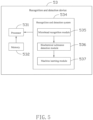
FIG. 4 is a diagrammatic view of a recognition and detection device of a biochemical substance detection system according to embodiment 4 of the present disclosure. -
FIG. 5 is a diagrammatic view of a recognition and detection device of a biochemical substance detection system according to embodiment 6 of the present disclosure. -
FIG. 6 is the flowchart of a biochemical substance detection method according to embodiment 7 of the present disclosure. - Symbols of main components:
- biochemical
substance detection system illumination system microscopic imaging system imaging system detection device illumination light source excitation light source image sensor -
microbead device -
fluorescent reaction vessel 16;processor -
memory detection system microbead recognition module substance detection module -
total reflection device 317;total reflection surface 3171 -
image reconstruction module 437;machine learning module 537 - Steps S61-S65
- Implementations of the disclosure will now be described, by way of embodiments only, with reference to the drawings. The described embodiments are only portions of the embodiments of the present disclosure, rather than all the embodiments. The disclosure is illustrative only, and changes may be made in the detail within the principles of the present disclosure. It will, therefore, be appreciated that the embodiments may be modified within the scope of the claims.
- It should be noted that when a component is considered to be "arranged on" another component, the component can be arranged directly on another component, or there may be an intermediate components therebetween. The term "and/or" as used herein includes all or any combination of one or more related listed items.
- Some existing microbeads, such as magnetic beads, have opaque substances or fluorescent substances marked therein. Pattern codes with different depths, shapes, and/or intervals are engraved around such microbead. All or a portion of the pattern codes are combined to form an identity number of the microbead. After microscopic imaging, the identity number of the microbead can be obtained by recognizing the pattern codes and their combinations engraved on the microbead. By exciting a fluorescent substance to emit light and detecting the intensity of the fluorescent light, an amount of a specific biochemical substance can be quantified.
- Referring to
FIG. 1 , a biochemical substance detection system is provided according to a first embodiment of the present disclosure. The biochemicalsubstance detection system 1 is used to detect pattern-codedmicrobeads 15 to obtain an amount of specific biochemical substances captured by the pattern-codedmicrobeads 15. The biochemicalsubstance detection system 1 includes a lens-freemicroscopic imaging system 11 and a recognition anddetection device 13. The lens-freemicroscopic imaging system 11, through microscopic imaging of themicrobeads 15, is used to obtain images of themicrobeads 15 and signals emitted by themicrobeads 15. The recognition anddetection device 13 is used to recognize themicrobeads 15 and the identity numbers of themicrobeads 15 from the images, and detect from the images an amount of the specific biochemical substance captured by each type ofmicrobead 15. - The lens-free
microscopic imaging system 11 includes anillumination system 11a and animaging system 11b. Theillumination system 11a includes anillumination light source 111 and anexcitation light source 112. Theimaging system 11b includes animage sensor 113. Theillumination light source 111 is used to emit illumination light to irradiate themicrobeads 15, so that the irradiatedmicrobeads 15 are projected onto theimage sensor 113 to form the images. Theexcitation light source 112 is used to emit excitation light to irradiate themicrobeads 15, and the specific biochemical substances captured by themicrobeads 15 are excited by the excitation light to respond with signals towards theimage sensor 113 to form the images. In order to prevent leakage of a portion of the excitation light onto theimage sensor 113, in this embodiment, afiltering device 114 matching a wavelength of the excitation light is arranged in front of theimage sensor 113. Thefiltering device 114 can be a filter device or a filter plate. Theimaging system 11b does not require a lens system of lenses. That is, a lens system is not provided between theimage sensor 113 and themicrobeads 15. - In this embodiment, the
microbeads 15 are pattern-coded magnetic beads of a transparent material. Themicrobeads 15 are placed in afluorescent reaction container 16. Generally, in order to realize multiplex detection, various types ofmicrobeads 15 are placed in thefluorescent reaction container 16, and each type ofmicrobead 15 has a same sequence of the pattern codes. Therefore, each type ofmicrobead 15 has a same identity number, and different types ofmicrobeads 15 have different identity numbers. Each type ofmicrobead 15 captures a biochemical substance, and different types ofmicrobeads 15 can capture different biochemical substances. When a type ofmicrobead 15 captures a specific biochemical substance, the specific biochemical substance captured by themicrobeads 15 is excited by the excitation light from theexcitation light source 112 and generates a fluorescent signal. By detecting the intensity of the fluorescent signal from each type ofmicrobead 15, the amount of the specific biochemical substance captured by such type ofmicrobead 15 is quantified. - In this embodiment, the
microbeads 15 are arranged so that a first orientation and a second orientation are defined. Theillumination light source 111 and theexcitation light source 112 are both arranged in the first orientation of themicrobeads 15. Thefiltering device 114 and theimage sensor 113 are arranged in the second orientation of themicrobeads 15. Theillumination light source 111 is a point light source or a light source array with limited spatial coherence (i.e., low spatial coherence). An imaging method performed by the lens-freemicroscopic imaging system 11 includes following steps. Theillumination light source 111 is powered on, which irradiates themicrobeads 15 from the first orientation to the second orientation, and the irradiatedmicrobeads 15 are projected onto theimage sensor 113. At the same time, theexcitation light source 112 is powered on, which emits the excitation light from the first orientation to the second orientation to irradiate themicrobeads 15, causing themicrobeads 15 to emit the fluorescent signals toward theimage sensor 113. Theimage sensor 113 collects the projections and the fluorescent signals of themicrobeads 15, and generates the images of themicrobeads 15 and the fluorescent signals. The images are output to the recognition anddetection device 13. The recognition anddetection device 13 recognizes the images to obtain the identity number of each type ofmicrobead 15, and to detect the amount of the specific biochemical substance captured by each type ofmicrobead 15. Specifically, the recognition anddetection device 13 is a computer device. The recognition anddetection device 13 includes aprocessor 131, amemory 132, and a computer program stored in thememory 132 and executed by theprocessor 131, such as a recognition anddetection system 134. The recognition anddetection system 134 is divided into a plurality of functional modules, such as amicrobead recognition module 135 and a biochemicalsubstance detection module 136, according to its functions. Themicrobead recognition module 135 is used to recognize themicrobeads 15 in the images and the identity numbers of themicrobeads 15. Specifically, themicrobead recognition module 135 recognizes themicrobeads 15 according to pre-built models or preset characteristics, recognizes the pattern codes of themicrobeads 15 according to the pre-built models or preset characteristics, and finally recognizes the identity numbers of themicrobeads 15 according to the sequences of the pattern codes of themicrobeads 15. The biochemicalsubstance detection module 136 is used to detect the intensity of the signal from each type ofmicrobead 15 in the images, and detect the amount of the specific biochemical substance captured by each type ofmicrobead 15 according to the intensity of the signal. - The biochemical
substance detection system 1 and detection method in this embodiment are applicable to the detection of pattern-coded beads, such pattern-coded beads which have sizes of 500 µm to 1 mm, and a distance between two feature points of the pattern codes is 50 µm or more. Assuming that a distance between theillumination light source 111 and themicrobeads 15 is z1, a distance between themicrobeads 15 and theimage sensor 113 is z2. The light carrying the information of themicrobeads 15, propagating over the distance z2, is captured by theimage sensor 113. In the existing process of semiconductors, a pixel size of theimage sensor 113 is generally large (a smallest pixel size at present is about 0.8 µm). Thus, in this embodiment, pixelation exists when theimage sensor 113 uses projection imaging (the projection imaging forms the images by the projections of the microbeads 15). Furthermore, defocus information of themicrobeads 15 is directly obtained. Thus, the recognition anddetection device 13 only needs the projection information of themicrobeads 15 to recognize the identity numbers of themicrobeads 15, without the need for reconstruction of focus information of themicrobeads 15 from under-sampling images. - Referring to
FIG. 2 , a biochemicalsubstance detection system 2 is provided according to a second embodiment of the present disclosure. The biochemicalsubstance detection system 2 is used to detect pattern-codedmicrobeads 25 to quantify an amount of specific biochemical substances captured by the pattern-codedmicrobeads 25. The biochemicalsubstance detection system 2 includes a lens-freemicroscopic imaging system 21 and a recognition anddetection device 23. The lens-freemicroscopic imaging system 21 is used to obtain images of themicrobeads 25 and signals emitted by themicrobeads 25 through microscopic imaging of themicrobeads 25. The recognition anddetection device 23 is used to recognize themicrobeads 25 in the images and the identity numbers of themicrobeads 25, and detect the amount of a specific biochemical substance captured by each type ofmicrobead 25. - The lens-free
microscopic imaging system 21 includes anillumination system 21a and animaging system 21b. Theillumination system 21a includes anillumination light source 211 and anexcitation light source 212. Theimaging system 21b includes animage sensor 213 and afiltering device 214 arranged in front of theimage sensor 213. Theillumination light source 211 is a point light source or a light source array with limited spatial coherence. Theillumination light source 211 is used to emit illumination light to irradiate themicrobeads 25, and the irradiatedmicrobeads 25 are projected onto theimage sensor 213 to form the images. In this embodiment, themicrobeads 25 are made of an opaque material, or a wavelength of light passing through themicrobeads 25 is not within a detection range of theimage sensor 213. Themicrobeads 25 are arranged so that a first orientation and a second orientation are defined. Theillumination light source 211 is arranged in the first orientation. Theexcitation light source 212, theimage sensor 213, and thefiltering device 214 are arranged in the second orientation. Theillumination light source 211 emits the illumination light from the first orientation to the second orientation, which irradiates themicrobeads 25 so that the irradiatedmicrobeads 25 are projected onto theimage sensor 213. At the same time, theexcitation light source 212 irradiates themicrobeads 25 from the second orientation to the first orientation, so that theexcitation microbead 25 generates a fluorescent signal that is projected onto theimage sensor 213. A lens system is not included in theimaging system 21b. That is, the lens system is not provided between theimage sensor 213 and themicrobeads 25. Theimage sensor 213 directly collects the projections and the fluorescent signals of themicrobeads 25, and generates the images of themicrobeads 25 and the fluorescent signals. The images are output to the recognition anddetection device 23. The recognition anddetection device 23 recognizes the images to obtain the identity number of each type ofmicrobead 25, and to detect the amount of the specific biochemical substance captured by each type ofmicrobead 25. The configuration of the recognition anddetection device 23 can refer toembodiment 1, which will not be repeated. - The biochemical
substance detection system 2 and detection method in this embodiment are applicable to the detection ofmicrobeads 25,such microbeads 25 which have sizes of 500 µm to 1 mm, and a distance between two feature points of the pattern codes is 50 µm or more. - Referring to
FIG. 3 , a biochemicalsubstance detection system 3 is provided according to a third embodiment of the present disclosure. The biochemicalsubstance detection system 3 is used to detect pattern-codedmicrobeads 35 to quantify an amount of specific biochemical substances captured by the pattern-codedmicrobeads 35. The biochemicalsubstance detection system 3 includes a lens-freemicroscopic imaging system 31 and a recognition anddetection device 33. The lens-freemicro imaging system 31, through microscopic imaging of themicrobeads 35, is used to obtain images of the identity numbers of themicrobeads 35 and signal emitted by themicrobeads 35. The recognition anddetection device 33 is used to recognize themicrobeads 35 in the images and the identity numbers of themicrobeads 35, and to detect the amount of the specific biochemical substance captured by each type ofmicrobead 35. - The lens-free
microscopic imaging system 31 includes anillumination system 31a and animaging system 31b. Theillumination system 31a includes anillumination light source 311, anexcitation light source 312, and atotal reflection device 317. Theimaging system 31b includes animage sensor 313 and afiltering device 314. Theillumination light source 311 is a point light source or a light source array with limited spatial coherence. Themicrobeads 35 are pattern-coded microbeads of an opaque material, or a wavelength of light that themicrobeads 35 can project is not within a detection range of theimage sensor 313. Themicrobeads 35 are arranged so that a first orientation and a second orientation are defined. Theillumination light source 311 and theexcitation light source 312 are arranged in the first orientation. Theimage sensor 313, thefiltering device 314, and thetotal reflection device 317 are arranged in the second orientation. Thefiltering device 314 is arranged in front of theimage sensor 313. Thetotal reflection device 317 is arranged in front of thefiltering device 314. Theillumination light source 311 emits the illumination light from the first orientation to the second orientation to irradiate themicrobeads 35, and the irradiatedmicrobeads 35 are projected onto theimage sensor 313. Theexcitation light source 312 emits the excitation light from the first orientation to the second orientation to irradiate themicrobeads 35, causing themicrobeads 35 to emit the fluorescent signals to theimage sensor 313. Thetotal reflection device 317 is arranged behind themicrobeads 35. Thetotal reflection device 317 has atotal reflection surface 3171. In this embodiment, thetotal reflection surface 3171 reflects the excitation light and allows the illumination light to pass through, causing the excitation light to irradiate a side of themicrobeads 35 facing theimage sensor 313. Thus, capture reagents on such side generate fluorescent signals. The fluorescent signals from themicrobeads 35 are projected to and recorded on theimage sensor 313. Theimage sensor 313 generates the images of themicrobeads 35 and the fluorescent signals. The images are output to the recognition anddetection device 33. The recognition anddetection device 33 recognizes the images to obtain the identity number of each type ofmicrobead 35, and to detect the amount of the specific biochemical substance captured by each type ofmicrobead 35. The setting of the recognition anddetection device 33 can refer toembodiment 1, which will not be repeated. - It can be understood that in other embodiments, not all parts of the
total reflection device 317 must be behind themicrobeads 35. Only at least a portion of thetotal reflection surface 3171 is required to be behind themicrobeads 35. - A distance z2 between the
microbeads 35 and theimage sensor 313 is a key factor of imaging quality. Compared with the second embodiment, arranging the excitation light source 32 in the first orientation can reduce the distance z2 between themicrobeads 35 and theimage sensor 33, so that the images of the projections of themicrobeads 35 and the fluorescent signals are clearer. - The biochemical
substance detection system 3 and detection method in this embodiment are applicable to the detection of pattern-codedmicrobeads 35,such microbeads 35 have sizes of 500 µm to 1 mm, and a distance between two feature points of the pattern codes is 50 µm or more. - In this embodiment, a lens-free microscopic imaging system uses an illumination light source with good spatial coherence and time coherence (i.e., high spatial coherence and high time coherence) is used to irradiate microbeads. Interference fringes are formed on an image sensor. The image sensor collects the interference fringes and fluorescent signals excited by an excitation light source, and generates images that are transmitted to a recognition and detection device. Referring to
FIG. 4 , the recognition anddetection device 43 includes aprocessor 431, amemory 432, and a computer program stored in thememory 432 and executed by theprocessor 431, such as a recognition anddetection system 434. In this embodiment, the recognition anddetection system 434 includes amicrobead recognition module 435, a biochemicalsubstance detection module 436, and animage reconstruction module 437. Theimage reconstruction module 437 is used to reconstruct the images output by the image sensor to obtain reconstructed images with higher resolutions. Themicrobead recognition module 435 is used to recognize the microbeads in the reconstructed images and the identity number of the microbeads. The biochemicalsubstance detection module 436 is used to detect the intensity of the signal from each type of microbead in the reconstructed images, and detect the amount of specific biochemical substance captured by each type of microbead according to the intensity of the signal. - Specifically, the
image reconstruction module 437 applies calculations to the interference fringes to obtain intensity information and phase information of the microbeads at a focus plane, thereby obtaining the identity numbers of the microbeads. The focus plane refers to a plane wherein clear images of the microbeads can be formed. The focus plane is a fictitious plane, not the focusing plane inside a traditional lens. - Images U(x, y) collected by the image sensor are formed by interferences between light U 0(x, y) scattered by the microbeads (object light) and reference light UR (x, y) directly passing through a transparent substrate and the filter without interference:

- Wherein, AR and A 0(x, y) are respectively the amplitude information of the reference light and the amplitude information of the object light (from microbeads), and ϕ 0(x, y) is the phase information of the object light (from microbeads). In this embodiment, the
image reconstruction module 437 uses a digital holographic reconstruction technology to recover the amplitude and phase information of the object light (from microbeads) based on light intensity information I(x, y) directly collected by the image sensor. The transparent substrate refers to a medium between the total reflection device and the filtering device. - The
image reconstruction module 437 uses digital holographic reconstruction technology to reconstruct the images obtained by the image sensor through algorithms. The reconstruction mainly includes: (1) phase recovery or conjugate image elimination, which are mainly used to eliminate diffraction effect caused by a spacing between the microbeads and the sensor; (2) super resolution imaging, which is mainly used to overcome a reduction of resolution caused by a pixel size of the image sensor, thereby achieving sub-pixel resolution without any lens. The two steps can be carried out in sequence, or carried out simultaneously by a phasor propagation method. The phasor propagation method can realize the super-resolution of pixels and phase recovery for the lens-free microscope images, and then realize image reconstruction. For an LED light source with poor spatial coherence, the spatial resolution of the reconstructed images can be further improved by a combination of the phasor propagation method and a point spread function deconvolution method. - In this embodiment, the following technical solutions can be used to obtain an illumination light source with good spatial coherence and temporal coherence.
- 1. A monochrome laser or a monochrome uniform laser is used as the illumination light source;
- 2. A monochrome LED or a monochrome light source is used as the illumination light source to improve time coherence;
- 3. A pinhole is arranged along a light path of monochrome laser, monochrome LED, or monochrome light source to improve spatial coherence;
- 4. The intensity of light from the illumination light source and a distance from the illumination light source to the microbeads are both increased.
- The above technical solutions can be combined according to needs.
- In addition to the use of a different illumination light source, the position of the illumination light source, and the position and function of other components in the lens-free microscopic imaging system in this embodiment can refer to any of the above-mentioned embodiments. For example, for transparent microbeads, the illumination light source, the excitation light source, the image sensor, and filtering device can be set with reference to
embodiment 1. For opaque microbeads or microbeads through which a wavelength of light is not within the detection range of the image sensor, the illumination light source, the excitation light source, the image sensor, and the filtering device can be set with reference toembodiment 2, or the illumination light source, the excitation light source, the image sensor, the filtering device, and the total reflection device can be set with reference toembodiment 3. - Compared with the above-mentioned embodiment that use a point light source or a light source array with limited spatial coherence to irradiate the microbeads for projection imaging, in this embodiment, the illumination light source with good spatial and temporal coherence is used to irradiate the microbeads to generate interference fringes. The digital holographic reconstruction image technology is then used to obtain the identity numbers of the microbeads, this has higher resolution and more accurate recognition.
- The lens-free microscopic imaging system in this embodiment can refer to
embodiments 1 to 3. The differences are mainly in respect of the recognition and detection device and the imaging method. - In this embodiment, Fourier laminated imaging is used to replace the above projection imaging to recognize the identity numbers of the microbeads. In this embodiment, the excitation light source is used to excite the microbeads to emit fluorescent signals. The fluorescent signals are collected by the image sensor and finally recognized by a specific computer device to quantify the amount of the captured specific molecules.
- In the above-mentioned
embodiments 1 to 4, accurate modeling for each step is needed in order to recognize the pattern codes of the microbeads and the identity numbers of the microbeads. The above-mentioned "each step" generally includes the placement of optical elements, modeling of the light sources and the illumination process, modeling of the detected objects, or modeling of the imaging process. In this embodiment, in addition to the use of the biochemical substance detection system in any one ofembodiments 1 to 5 to perform the biochemical substance detection, the biochemical substance detection system also includes a machine learning function, which automatically learns from each detection result to extract different characteristic values for the biochemical substance detection system to perform subsequent detections. - Referring to
FIG. 5 , the recognition anddetection device 53 includes aprocessor 531, amemory 532, and a computer program stored in thememory 532 and executed by theprocessor 531, such as a recognition anddetection system 534. In this embodiment, the recognition anddetection system 534 includes amicrobead recognition module 535, a biochemicalsubstance detection module 536, and amachine learning module 537. Themicrobead recognition module 535 and the biochemicalsubstance detection module 536 basically have the same functions as those of themicrobead recognition module 135 and the biochemicalsubstance detection module 136 inembodiment 1, which will not be repeated. Themachine learning module 537 is used to apply a machine learning method, such as a supervised learning method or an unsupervised learning method, to train through a large number of data sets, thereby realizing the extraction of a large number of characteristic values and the pattern codes of the microbeads. By adding themachine learning module 537, the biochemical material detection system automatically learns from each detection result to obtain the characteristic values. Thus, accurate modeling for each step of the entire imaging process is avoided. The recognition, segmentation, extraction, and counting of the microbeads in a large field of view, as well as the recognition and counting of identity numbers of the microbeads are realized. The supervised learning method substantially includes data preprocessing, neural network construction, network training, and optimal solution preserving. - Referring to
FIG. 6 , a flowchart of a biochemical substance detection method is provided according to a seventh embodiment of the present disclosure. The sequence of some steps in the flowchart may be changed, and some steps may be omitted. For convenience of explanation, only the parts related to the embodiments of the present disclosure are shown. - In this embodiment, the biochemical substance detection method is used to form images of microbeads having pattern codes. The microbeads are used to capture specific biochemical substances. The biochemical substance detection method includes a lens-free microscopic imaging method and a recognition and detection method.
- The lens-free microscopic imaging method include following steps.
- Step S61, the microbeads are placed between the illumination light source and the image sensor, causing the microbeads to be capable of being illuminated by illumination light from the illumination light source and project their own images on the image sensor.
- Step S62, the illumination light source is powered on, which emits the illumination light.
- Step S63, the excitation light source is powered on, which emits the excitation light to irradiate the microbeads, so that the specific biochemical substances captured by the microbeads or the biochemical substances generated during the capture process are excited to emit specific signals. The above capture process will generally initialize a series of biochemical reaction processes. The capture process includes but is not limited to a one-step method, sandwich method, or quenching method.
- Step S64, the image sensor collects an image of the microbeads and an image of the specific signals. Thus, the images of at least two channels are obtained.
- The recognition and detection method include following steps.
- Step S65, the images are received. The microbeads in the images and the identity number of each of the microbeads are recognized. The amount of specific biochemical substance captured by each type of microbead is also detected. The microbeads with a same identity number are classified into a single type.
- Step S65 may specifically include following steps. The images are received. Then, the microbeads in the images and the identity number of each microbead are recognized in one channel. The position and intensity of the fluorescent signals are recognized in the other channel. The position of the fluorescent signals is registered with the position of the microbeads, or the images of the two channels are registered. The identity number of each microbead, and the presence or absence of the corresponding specific signal and the intensity of such signal are detected. The microbeads with the same identity number are classified into a single type. Through the corresponding signal of multiple microbeads classified in a same type, the intensity and distribution of the signal from this type of microbeads are determined after multiple sampling process.
- In another embodiment, the lens-free microscopic imaging method of the biochemical substance detection method also includes configuring the illumination light source as a point light source or a light source array with low spatial coherence.
- In another embodiment, the lens-free microscopic imaging method of the biochemical substance detection method also includes irradiating the microbeads by the illumination light emitted by the illumination light source, so that the microbeads are projected on the image sensor.
- In another embodiment, the lens-free microscopic imaging method of the biochemical substance detection method also includes configuring the illumination light source to have high temporal coherence and high spatial coherence.
- In another embodiment, the lens-free microscopic imaging method of the biochemical substance detection method also includes irradiating the microbeads by the illumination light emitted by the illumination light source, thereby forming interference fringes on the image sensor. The interference fringes are then collected by the image sensor.
- In another embodiment, the recognition and detection method of the biochemical substance detection method specifically includes recognizing the microbeads in the images and the pattern codes of each microbead. The identity number of each microbead is recognized according to the sequence of the pattern codes of each microbead. The intensity of the specific signal generated by each type of microbead in the images is detected. The amount of the specific biochemical substance captured by each type of microbead is then detected according to the intensity of the specific signal.
- In another embodiment, before "recognizing the microbeads in the images and the identity number of each microbead and detecting the amount of specific biochemical substances captured by each type of microbead", the recognition and detection method of the biochemical substance detection method also includes reconstructing the images output by the image sensor, or reconstructing the images output by the image sensor through a digital holographic reconstruction technology.
- In another embodiment, the recognition and detection method of the biochemical substance detection method also includes automatically learning various results of recognition and detection during the recognition and detection processes, and extracting the characteristic values.
- In the above-mentioned
embodiments 1 to 7, in order to further improve the imaging resolution, the following technical solutions or a combination thereof can be used as needed. - 1. The distance between the filtering device and the image sensor is reduced. For example, the filtering device can be arranged on the image sensor, causing the pixels of the filtering device to correspond one-to-one to the pixels of the image sensor. Thus, the distance z2 from the microbeads to the image sensor is reduced;
- 2. Optical fiber arrays closely arranged are used to relay the excitation light;
- 3. When a mask of nanostructures is arranged close to the microbeads (the object to be detected), the point spread function of the whole optical system is no longer space invariant but depends on the mask of nanostructures. Specifically, the point spread function can form specific patterns and rules, making the image processing more convenient and the positioning more accurate.
- 4. Excitation points that are precisely and closely arranged and the Talbot effect are used to improve the resolution;
- 5. In the process of image reconstruction, a deconvolution calculation method, such as Lucy Richardson algorithms, is used to improve the resolution.
- Therefore, the lens-free microscopic imaging system and method and the biochemical substance detection system and method according to the embodiment of the present disclosure are used to replace the existing optical microscope to detect the pattern-coded microbeads. The processes of lens focusing and repeatedly shifting the field of view when using the existing optical microscope are avoided. The image processing is only needed to achieve ultra-high resolution, so the imaging speed is faster. Since the optical lens system is omitted, the lens-free microscopic imaging system is more compact and the cost is lower. The field of view is larger. All the pattern-coded microbeads in the reaction vessel can be traversed without the need to rotate the field of view by a slider mechanism.
- Finally, even though information and advantages of the present embodiments have been set forth in the foregoing description, together with details of the structures and functions of the present embodiments, the disclosure is illustrative only. Changes may be made in detail, especially in matters of shape, size, and arrangement of parts within the principles of the present exemplary embodiments, to the full extent indicated by the plain meaning of the terms in which the appended claims are expressed.
Claims (15)
- A lens-free microscopic imaging system (11, 21, 31), the lens-free microscopic imaging system (11, 21, 31) configured for imaging microbeads (15, 25, 35), each of the microbeads (15, 25, 35) has opaque substances or fluorescent substances marked therein, the lens-free microscopic imaging system (11, 21, 31) comprising:an illumination system (11a, 21a, 31a); andan imaging system (11b, 21b, 31b);wherein the illumination system (11a, 21a, 31a) comprises an illumination light source (111, 211, 311) and an excitation light source (112, 212, or 312), the imaging system (11b, 21b, 31b) comprises an image sensor (113, 213, 313), the illumination light source (111, 211, 311) is configured to emit illumination light to irradiate the microbeads (15, 25, 35), causing the irradiated microbeads (15, 25, 35) to be imaged on the image sensor (113, 213, 313), the excitation light source (112, 212, or 312) is configured to emit excitation light to excite the microbeads (15, 25, 35) to generate specific signals, the image sensor (113, 213, 313) is configured to collect images of the microbeads (15, 25, 35) and of the specific signals,characterized in that the system is configured to quantify an amount of specific biochemical substances captured by various types of microbeads (15, 25, 35), with each of the microbeads (15, 25, 35) having pattern codes with different depths, shapes, and/or intervals engraved around the microbead (15, 25, 35), and all or a portion of the pattern codes are combined to form an identity number of the microbead (15, 25, 35), and each type of microbeads (15, 25, 35) has a same identity number, each type of microbeads (15, 25, 35) captures a biochemical substance, different types of microbeads (15, 25, 35) capture different biochemical substances, the system is further configured to recognize the identity number of the microbead (15, 25, 35) by the pattern codes in the images, and to quantify an amount of a specific biochemical substance captured by each type of microbeads (15, 25, 35) by an intensity of the specific signals in the images.
- The lens-free microscopic imaging system (11, 21, 31) according to claim 1, characterized in that, the illumination light irradiates the microbeads (15, 25, 35), causing the images of the irradiated microbeads (15, 25, 35) to be projected on the image sensor (113, 213, 313).
- The lens-free microscopic imaging system (11, 21, 31) according to claim 1, characterized in that, the illumination light further forms interference fringes on the image sensor (113, 213, 313), and the interference fringes are collected by the image sensor (113, 213, 313).
- The lens-free microscopic imaging system (11, 21, 31) according to claim 3, characterized in that, a pinhole is arranged on an optical path from the illumination light source (111, 211, 311) to the microbeads (15, 25, 35).
- The lens-free microscopic imaging system (11, 21, 31) according to claim 1, characterized in that, the illumination light source (111, 211, 311) is configured to emit the illumination light from a first orientation to a second orientation to irradiate the microbeads (15, 25, 35), and the excitation light source (112, 212, or 312) is configured to emit the excitation light from the first orientation to the second orientation.
- The lens-free micro imaging system (31) according to claim 5, characterized in that, the illumination system (31a) further comprises a total reflection device (317), the total reflection device (317) comprises a total reflection surface (3171), and the total reflection surface (3171) is configured to reflect the excitation light emitted by the excitation light source (112, 212, or 312) to the microbeads (15, 25, 35).
- The lens-free microscopic imaging system (31) according to claim 6, characterized in that, the total reflection surface (3171) is arranged in the second orientation, and is configured to reflect the excitation light from the second orientation to the first orientation.
- The lens-free microscopic imaging system (11, 21, 31) according to claim 1, characterized in that, the illumination light source (111, 211, 311) is configured to emit the illumination light from a first orientation to a second orientation to irradiate the microbeads (15, 25, 35), and the excitation light source (112, 212, or 312) is configured to emit the excitation light from the second orientation to the first orientation.
- The lens-free microscopic imaging system (11, 21, 31) according to claim 1, characterized in that, further comprising a filtering device (114, 214, 314) in front of or on the image sensor (113, 213, 313).
- A lens-free microscopic imaging method, the lens-free microscopic imaging method configured for imaging microbeads (15, 25, 35), each of the microbeads has opaque substances or fluorescent substances marked therein, the microbeads (15, 25, 35) being configured to capture specific biochemical substances, the lens-free microscopic imaging method comprising:disposing the microbeads (15, 25, 35) between an illumination light source (111, 211, 311) and an image sensor (113, 213, 313);powering on the illumination light source (111, 211, 311) to emit illumination light towards the microbeads (15, 25, 35), causing the microbeads (15, 25, 35) to be imaged on the image sensor (113, 213, 313);powering on the excitation light source (112, 212, or 312) to emit excitation light towards the microbeads (15, 25, 35), causing the specific biochemical substances to generate specific signals;collecting images of the microbeads (15, 25, 35) and the specific signals,characterized in that various types of microbeads (15, 25, 35) are disposed between the illumination source (111, 211, 311) and the image sensor (113, 213, 313), wherein each of the microbeads (15, 25, 35) further has pattern codes with different depths, shapes, and/or intervals engraved around the microbead (15, 25, 35), all or a portion of the pattern codes are combined to form an identity number of the microbead (15, 25, 35), and each type of microbeads (15, 25, 35) has a same identity number, each type of microbeads (15, 25, 35) captures a biochemical substance, different types of microbeads (15, 25, 35) capture different biochemical substances, the identity number of the microbead (15, 25, 35) is recognizable by the pattern codes in the images, and an amount of a specific biochemical substance captured by each type of microbeads (15, 25, 35) is quantified by an intensity of the specific signals in the images.
- The lens-free microscopic imaging method according to claim 10, characterized in that, the illumination light irradiates the microbeads (15, 25, 35), causing the irradiated microbeads (15, 25, 35) to be projected on the image sensor (113, 213, 313).
- The lens-free microscopic imaging method according to claim 10, characterized in that, the illumination light further forms interference fringes on the image sensor (113, 213, 313), and the interference fringes are collected by the image sensor (113, 213, 313).
- A biochemical substance detection system (1, 2, 3), characterized in that, comprising:a lens-free microscopic imaging system (11, 21, 31) according to any one of claims 1-9; anda recognition and detection device (13, 23, 33, 43, 53) configured to receive the images output by the image sensor (113, 213, 313), recognize the microbeads (15, 25, 35) in the images, an identity number of each of the microbeads (15, 25, 35), and an amount of the specific biochemical substances captured by each type of microbead (15, 25, 35), the microbeads (15, 25, 35) with a same identity number are classified into one type of microbead (15, 25, 35).
- The biochemical substance detection system (1, 2, 3) according to claim 13, characterized in that, the recognition and detection device (13, 23, 33, 43, 53) comprises a recognition and detection system (134, 234, 334, 434, 534), the recognition and detection system (134, 234, 334, 434, 534) comprises a microbead recognition module (135, 235, 335, 435, 535) and a biochemical substance detection module (136, 236, 336, 436, 536), the microbead recognition module (135, 235, 335, 435, 535) is configured to recognize the microbeads (15, 25, 35) in the images, the pattern codes of each of the microbeads (15, 25, 35), and the identity number of each of the microbeads (15, 25, 35) according to a sequence of the pattern codes of each of the microbeads (15, 25, 35); the biochemical substance detection module (136, 236, 336, 436, 536) is configured to detect in the images an intensity of one of the specific signals sent by each type of microbead (15, 25, 35), and detect an amount of one of the specific biochemical substances captured by each type of microbead (15, 25, 35) according to the intensity of the specific signal.
- The biochemical substance detection system (1, 2, 3) according to claim 14, characterized in that, the recognition and detection system (434) further comprises an image reconstruction module (437), the image reconstruction module (437) is configured to reconstruct the images output by the image sensor (113, 213, 313), and output reconstructed images to the microbead recognition module (435); the recognition and detection system (534) further comprises a machine learning module (537), the machine learning module (537) is configured to automatically learn recognition results from the microbead recognition module (535) and extract characteristic values for subsequent recognitions by the microbead recognition module (535).
Applications Claiming Priority (1)
| Application Number | Priority Date | Filing Date | Title |
|---|---|---|---|
| PCT/CN2020/083738 WO2021203291A1 (en) | 2020-04-08 | 2020-04-08 | Lens-free microscopic imaging system and method, and biochemical substance detection system and method |
Publications (3)
| Publication Number | Publication Date |
|---|---|
| EP4134725A1 EP4134725A1 (en) | 2023-02-15 |
| EP4134725A4 EP4134725A4 (en) | 2024-01-03 |
| EP4134725B1 true EP4134725B1 (en) | 2025-02-26 |
Family
ID=78022666
Family Applications (1)
| Application Number | Title | Priority Date | Filing Date |
|---|---|---|---|
| EP20930394.0A Active EP4134725B1 (en) | 2020-04-08 | 2020-04-08 | Lens-free microscopic imaging system and method, and biochemical substance detection system and method |
Country Status (5)
| Country | Link |
|---|---|
| US (1) | US12099177B2 (en) |
| EP (1) | EP4134725B1 (en) |
| JP (1) | JP7478248B2 (en) |
| CN (1) | CN115004076B (en) |
| WO (1) | WO2021203291A1 (en) |
Families Citing this family (1)
| Publication number | Priority date | Publication date | Assignee | Title |
|---|---|---|---|---|
| JP2025002197A (en) * | 2023-06-22 | 2025-01-09 | 株式会社ジャパンディスプレイ | Detection device and detection system |
Family Cites Families (25)
| Publication number | Priority date | Publication date | Assignee | Title |
|---|---|---|---|---|
| JP2003139773A (en) * | 2001-10-31 | 2003-05-14 | Ebara Corp | Affinity reaction probe bead, and detection system |
| US20090201504A1 (en) * | 2005-08-09 | 2009-08-13 | Maxwell Sensors, Inc. | Hydrodynamic focusing for analyzing rectangular microbeads |
| US7858307B2 (en) * | 2005-08-09 | 2010-12-28 | Maxwell Sensors, Inc. | Light transmitted assay beads |
| JP2010536029A (en) * | 2007-08-08 | 2010-11-25 | マックスウェル センサーズ インコーポレイテッド | Apparatus and method for digital magnetic bead analysis |
| AU2009296526B2 (en) * | 2008-09-24 | 2015-11-19 | First Light Diagnostics, Inc. | Method for detecting analytes |
| US20100157086A1 (en) * | 2008-12-15 | 2010-06-24 | Illumina, Inc | Dynamic autofocus method and system for assay imager |
| US20140152801A1 (en) * | 2009-10-28 | 2014-06-05 | Alentic Microscience Inc. | Detecting and Using Light Representative of a Sample |
| US20140160236A1 (en) * | 2011-07-29 | 2014-06-12 | The Regents Of The University Of California | Lensfree holographic microscopy using wetting films |
| CN102508356B (en) | 2011-09-30 | 2014-09-10 | 浙江大学 | Lensless microscopic imaging method based on optical projection and device thereof |
| EP2602608B1 (en) * | 2011-12-07 | 2016-09-14 | Imec | Analysis and sorting of biological cells in flow |
| AU2013295679A1 (en) * | 2012-07-25 | 2015-01-29 | Theranos, Inc. | Image analysis and measurement of biological samples |
| FR3002634B1 (en) * | 2013-02-28 | 2015-04-10 | Commissariat Energie Atomique | METHOD OF OBSERVING AT LEAST ONE OBJECT, SUCH AS A BIOLOGICAL ENTITY, AND ASSOCIATED IMAGING SYSTEM |
| CN107111057A (en) * | 2014-12-29 | 2017-08-29 | Imec 非营利协会 | Photo-coupler |
| WO2017066102A1 (en) * | 2015-10-15 | 2017-04-20 | The Regents Of The University Of California | System and method for droplet formation and manipulation using ferrofluids |
| WO2017104026A1 (en) * | 2015-12-16 | 2017-06-22 | オリンパス株式会社 | Fluorescence observation device, fluorescence observation system, and incubator |
| CN107069391B (en) * | 2017-02-10 | 2020-07-17 | 北京大学 | Femtosecond pulse laser modulator and miniature two-photon microscopic imaging device with same |
| EP3432194A1 (en) * | 2017-07-16 | 2019-01-23 | IMEC vzw | Cell recognition |
| US10753851B2 (en) * | 2017-11-28 | 2020-08-25 | Alentic Microscience Inc. | Classifying microbeads in near-field imaging |
| CN108362651B (en) * | 2018-01-26 | 2021-07-16 | 绍兴柯桥睿宇光电科技有限公司 | Portable lens-free multispectral microscopic imaging system and method |
| CN109112176A (en) * | 2018-09-04 | 2019-01-01 | 武汉尚码生物科技有限公司 | A kind of microballoon code carrier and its application |
| CN109001900A (en) * | 2018-09-05 | 2018-12-14 | 南京大学 | A kind of micro imaging system and method for light field and fluorescent dual module state |
| US12020165B2 (en) * | 2018-11-15 | 2024-06-25 | The Regents Of The University Of California | System and method for transforming holographic microscopy images to microscopy images of various modalities |
| JP7039071B2 (en) * | 2019-03-14 | 2022-03-22 | サイトロニクス株式会社 | Monitoring device and monitoring system |
| CN109884018B (en) * | 2019-03-22 | 2020-09-18 | 华中科技大学 | A method and system for submicron lensless microscopic imaging based on neural network |
| US10684278B1 (en) * | 2019-03-28 | 2020-06-16 | Alentic Microscience Inc. | Bead-based analysis of a sample |
-
2020
- 2020-04-08 JP JP2022559628A patent/JP7478248B2/en active Active
- 2020-04-08 EP EP20930394.0A patent/EP4134725B1/en active Active
- 2020-04-08 US US17/913,958 patent/US12099177B2/en active Active
- 2020-04-08 WO PCT/CN2020/083738 patent/WO2021203291A1/en not_active Ceased
- 2020-04-08 CN CN202080094159.8A patent/CN115004076B/en active Active
Also Published As
| Publication number | Publication date |
|---|---|
| CN115004076B (en) | 2024-05-10 |
| JP2023519423A (en) | 2023-05-10 |
| US12099177B2 (en) | 2024-09-24 |
| JP7478248B2 (en) | 2024-05-02 |
| EP4134725A4 (en) | 2024-01-03 |
| CN115004076A (en) | 2022-09-02 |
| US20230124060A1 (en) | 2023-04-20 |
| EP4134725A1 (en) | 2023-02-15 |
| WO2021203291A1 (en) | 2021-10-14 |
Similar Documents
| Publication | Publication Date | Title |
|---|---|---|
| US20230384208A1 (en) | Image-based cell sorting systems and methods | |
| US20240273719A1 (en) | Image enhancement to enable improved nuclei detection and segmentation | |
| EP2491366B1 (en) | Incoherent lensfree cell holography and microscopy on a chip | |
| US7948632B2 (en) | Method and apparatus for analysis of a sample of cells | |
| EP3729053B1 (en) | Fast and robust fourier domain-based cell differentiation | |
| US20220299421A1 (en) | Systems, devices and methods for three-dimensional imaging of moving particles | |
| JP2015505983A (en) | Material analysis system, method and apparatus | |
| CN108693098B (en) | Cell counting analysis method for cell sample | |
| KR101071439B1 (en) | Imaging Device | |
| CN105190690A (en) | Image quality assessment of microscopy images | |
| CN101943663A (en) | Measuring analytical system and measuring analytical method for distinguishing diffraction image of particles automatically | |
| WO2009020506A1 (en) | Apparatus and method for digital magnetic beads analysis | |
| EP4479977A1 (en) | Synthetic generation of immunohistochemical special stains | |
| KR20210117796A (en) | Method and apparatus for classifying of cell subtype using three-dimensional refractive index tomogram and machine learning | |
| US12099177B2 (en) | Lens-free microscopic imaging system and method, and biochemical substance detection system and method | |
| US12038370B2 (en) | Magnetically modulated computational cytometer and methods of use | |
| Hu et al. | Enhanced resolution 3D digital cytology and pathology with dual-view inverted selective plane illumination microscopy | |
| HK40072749A (en) | Lens-free microscopic imaging system and method, and biochemical substance detection system and method | |
| HK40072749B (en) | Lens-free microscopic imaging system and method, and biochemical substance detection system and method | |
| Lee et al. | Deep learning-enabled digital resolution molecular diagnostics in photonic resonator absorption microscopy | |
| Potter | Lens-Free Holographic Microscopy With Deep Learning Image Classification for Biosensing and Disease Diagnosis | |
| CN121039484A (en) | Detection methods, detection systems, noise removal model training methods, and noise removal model training systems |
Legal Events
| Date | Code | Title | Description |
|---|---|---|---|
| STAA | Information on the status of an ep patent application or granted ep patent |
Free format text: STATUS: THE INTERNATIONAL PUBLICATION HAS BEEN MADE |
|
| PUAI | Public reference made under article 153(3) epc to a published international application that has entered the european phase |
Free format text: ORIGINAL CODE: 0009012 |
|
| STAA | Information on the status of an ep patent application or granted ep patent |
Free format text: STATUS: REQUEST FOR EXAMINATION WAS MADE |
|
| 17P | Request for examination filed |
Effective date: 20221107 |
|
| AK | Designated contracting states |
Kind code of ref document: A1 Designated state(s): AL AT BE BG CH CY CZ DE DK EE ES FI FR GB GR HR HU IE IS IT LI LT LU LV MC MK MT NL NO PL PT RO RS SE SI SK SM TR |
|
| DAV | Request for validation of the european patent (deleted) | ||
| DAX | Request for extension of the european patent (deleted) | ||
| A4 | Supplementary search report drawn up and despatched |
Effective date: 20231205 |
|
| RIC1 | Information provided on ipc code assigned before grant |
Ipc: G02B 5/28 20060101ALN20231129BHEP Ipc: G02B 21/36 20060101AFI20231129BHEP |
|
| GRAP | Despatch of communication of intention to grant a patent |
Free format text: ORIGINAL CODE: EPIDOSNIGR1 |
|
| STAA | Information on the status of an ep patent application or granted ep patent |
Free format text: STATUS: GRANT OF PATENT IS INTENDED |
|
| RIC1 | Information provided on ipc code assigned before grant |
Ipc: G02B 5/28 20060101ALN20241018BHEP Ipc: G02B 21/36 20060101AFI20241018BHEP |
|
| INTG | Intention to grant announced |
Effective date: 20241030 |
|
| GRAS | Grant fee paid |
Free format text: ORIGINAL CODE: EPIDOSNIGR3 |
|
| GRAA | (expected) grant |
Free format text: ORIGINAL CODE: 0009210 |
|
| STAA | Information on the status of an ep patent application or granted ep patent |
Free format text: STATUS: THE PATENT HAS BEEN GRANTED |
|
| AK | Designated contracting states |
Kind code of ref document: B1 Designated state(s): AL AT BE BG CH CY CZ DE DK EE ES FI FR GB GR HR HU IE IS IT LI LT LU LV MC MK MT NL NO PL PT RO RS SE SI SK SM TR |
|
| REG | Reference to a national code |
Ref country code: GB Ref legal event code: FG4D |
|
| REG | Reference to a national code |
Ref country code: CH Ref legal event code: EP |
|
| REG | Reference to a national code |
Ref country code: DE Ref legal event code: R096 Ref document number: 602020047030 Country of ref document: DE |
|
| REG | Reference to a national code |
Ref country code: IE Ref legal event code: FG4D |
|
| P01 | Opt-out of the competence of the unified patent court (upc) registered |
Free format text: CASE NUMBER: APP_10567/2025 Effective date: 20250304 |
|
| REG | Reference to a national code |
Ref country code: NL Ref legal event code: MP Effective date: 20250226 |
|
| PG25 | Lapsed in a contracting state [announced via postgrant information from national office to epo] |
Ref country code: RS Free format text: LAPSE BECAUSE OF FAILURE TO SUBMIT A TRANSLATION OF THE DESCRIPTION OR TO PAY THE FEE WITHIN THE PRESCRIBED TIME-LIMIT Effective date: 20250526 |
|
| PG25 | Lapsed in a contracting state [announced via postgrant information from national office to epo] |
Ref country code: FI Free format text: LAPSE BECAUSE OF FAILURE TO SUBMIT A TRANSLATION OF THE DESCRIPTION OR TO PAY THE FEE WITHIN THE PRESCRIBED TIME-LIMIT Effective date: 20250226 |
|
| PG25 | Lapsed in a contracting state [announced via postgrant information from national office to epo] |
Ref country code: PL Free format text: LAPSE BECAUSE OF FAILURE TO SUBMIT A TRANSLATION OF THE DESCRIPTION OR TO PAY THE FEE WITHIN THE PRESCRIBED TIME-LIMIT Effective date: 20250226 |
|
| PGFP | Annual fee paid to national office [announced via postgrant information from national office to epo] |
Ref country code: DE Payment date: 20250411 Year of fee payment: 6 |
|
| PG25 | Lapsed in a contracting state [announced via postgrant information from national office to epo] |
Ref country code: ES Free format text: LAPSE BECAUSE OF FAILURE TO SUBMIT A TRANSLATION OF THE DESCRIPTION OR TO PAY THE FEE WITHIN THE PRESCRIBED TIME-LIMIT Effective date: 20250226 |
|
| PGFP | Annual fee paid to national office [announced via postgrant information from national office to epo] |
Ref country code: GB Payment date: 20250417 Year of fee payment: 6 |
|
| REG | Reference to a national code |
Ref country code: LT Ref legal event code: MG9D |
|
| PG25 | Lapsed in a contracting state [announced via postgrant information from national office to epo] |
Ref country code: NO Free format text: LAPSE BECAUSE OF FAILURE TO SUBMIT A TRANSLATION OF THE DESCRIPTION OR TO PAY THE FEE WITHIN THE PRESCRIBED TIME-LIMIT Effective date: 20250526 Ref country code: IS Free format text: LAPSE BECAUSE OF FAILURE TO SUBMIT A TRANSLATION OF THE DESCRIPTION OR TO PAY THE FEE WITHIN THE PRESCRIBED TIME-LIMIT Effective date: 20250626 |
|
| PG25 | Lapsed in a contracting state [announced via postgrant information from national office to epo] |
Ref country code: NL Free format text: LAPSE BECAUSE OF FAILURE TO SUBMIT A TRANSLATION OF THE DESCRIPTION OR TO PAY THE FEE WITHIN THE PRESCRIBED TIME-LIMIT Effective date: 20250226 |
|
| PG25 | Lapsed in a contracting state [announced via postgrant information from national office to epo] |
Ref country code: HR Free format text: LAPSE BECAUSE OF FAILURE TO SUBMIT A TRANSLATION OF THE DESCRIPTION OR TO PAY THE FEE WITHIN THE PRESCRIBED TIME-LIMIT Effective date: 20250226 |
|
| PG25 | Lapsed in a contracting state [announced via postgrant information from national office to epo] |
Ref country code: LV Free format text: LAPSE BECAUSE OF FAILURE TO SUBMIT A TRANSLATION OF THE DESCRIPTION OR TO PAY THE FEE WITHIN THE PRESCRIBED TIME-LIMIT Effective date: 20250226 Ref country code: PT Free format text: LAPSE BECAUSE OF FAILURE TO SUBMIT A TRANSLATION OF THE DESCRIPTION OR TO PAY THE FEE WITHIN THE PRESCRIBED TIME-LIMIT Effective date: 20250626 |
|
| PGFP | Annual fee paid to national office [announced via postgrant information from national office to epo] |
Ref country code: FR Payment date: 20250429 Year of fee payment: 6 |
|
| PG25 | Lapsed in a contracting state [announced via postgrant information from national office to epo] |
Ref country code: BG Free format text: LAPSE BECAUSE OF FAILURE TO SUBMIT A TRANSLATION OF THE DESCRIPTION OR TO PAY THE FEE WITHIN THE PRESCRIBED TIME-LIMIT Effective date: 20250226 Ref country code: GR Free format text: LAPSE BECAUSE OF FAILURE TO SUBMIT A TRANSLATION OF THE DESCRIPTION OR TO PAY THE FEE WITHIN THE PRESCRIBED TIME-LIMIT Effective date: 20250527 |
|
| REG | Reference to a national code |
Ref country code: AT Ref legal event code: MK05 Ref document number: 1771185 Country of ref document: AT Kind code of ref document: T Effective date: 20250226 |
|
| PG25 | Lapsed in a contracting state [announced via postgrant information from national office to epo] |
Ref country code: SE Free format text: LAPSE BECAUSE OF FAILURE TO SUBMIT A TRANSLATION OF THE DESCRIPTION OR TO PAY THE FEE WITHIN THE PRESCRIBED TIME-LIMIT Effective date: 20250226 |
|
| PG25 | Lapsed in a contracting state [announced via postgrant information from national office to epo] |
Ref country code: SM Free format text: LAPSE BECAUSE OF FAILURE TO SUBMIT A TRANSLATION OF THE DESCRIPTION OR TO PAY THE FEE WITHIN THE PRESCRIBED TIME-LIMIT Effective date: 20250226 |
|
| PG25 | Lapsed in a contracting state [announced via postgrant information from national office to epo] |
Ref country code: DK Free format text: LAPSE BECAUSE OF FAILURE TO SUBMIT A TRANSLATION OF THE DESCRIPTION OR TO PAY THE FEE WITHIN THE PRESCRIBED TIME-LIMIT Effective date: 20250226 |
|
| PG25 | Lapsed in a contracting state [announced via postgrant information from national office to epo] |
Ref country code: IT Free format text: LAPSE BECAUSE OF FAILURE TO SUBMIT A TRANSLATION OF THE DESCRIPTION OR TO PAY THE FEE WITHIN THE PRESCRIBED TIME-LIMIT Effective date: 20250226 |
|
| PG25 | Lapsed in a contracting state [announced via postgrant information from national office to epo] |
Ref country code: AT Free format text: LAPSE BECAUSE OF FAILURE TO SUBMIT A TRANSLATION OF THE DESCRIPTION OR TO PAY THE FEE WITHIN THE PRESCRIBED TIME-LIMIT Effective date: 20250226 |
|
| PG25 | Lapsed in a contracting state [announced via postgrant information from national office to epo] |
Ref country code: EE Free format text: LAPSE BECAUSE OF FAILURE TO SUBMIT A TRANSLATION OF THE DESCRIPTION OR TO PAY THE FEE WITHIN THE PRESCRIBED TIME-LIMIT Effective date: 20250226 Ref country code: CZ Free format text: LAPSE BECAUSE OF FAILURE TO SUBMIT A TRANSLATION OF THE DESCRIPTION OR TO PAY THE FEE WITHIN THE PRESCRIBED TIME-LIMIT Effective date: 20250226 |
|
| PG25 | Lapsed in a contracting state [announced via postgrant information from national office to epo] |
Ref country code: RO Free format text: LAPSE BECAUSE OF FAILURE TO SUBMIT A TRANSLATION OF THE DESCRIPTION OR TO PAY THE FEE WITHIN THE PRESCRIBED TIME-LIMIT Effective date: 20250226 |
|
| PG25 | Lapsed in a contracting state [announced via postgrant information from national office to epo] |
Ref country code: SK Free format text: LAPSE BECAUSE OF FAILURE TO SUBMIT A TRANSLATION OF THE DESCRIPTION OR TO PAY THE FEE WITHIN THE PRESCRIBED TIME-LIMIT Effective date: 20250226 |
|
| REG | Reference to a national code |
Ref country code: CH Ref legal event code: H13 Free format text: ST27 STATUS EVENT CODE: U-0-0-H10-H13 (AS PROVIDED BY THE NATIONAL OFFICE) Effective date: 20251125 |
|
| REG | Reference to a national code |
Ref country code: DE Ref legal event code: R097 Ref document number: 602020047030 Country of ref document: DE |
|
| PG25 | Lapsed in a contracting state [announced via postgrant information from national office to epo] |
Ref country code: LU Free format text: LAPSE BECAUSE OF NON-PAYMENT OF DUE FEES Effective date: 20250408 |
|
| PG25 | Lapsed in a contracting state [announced via postgrant information from national office to epo] |
Ref country code: MC Free format text: LAPSE BECAUSE OF FAILURE TO SUBMIT A TRANSLATION OF THE DESCRIPTION OR TO PAY THE FEE WITHIN THE PRESCRIBED TIME-LIMIT Effective date: 20250226 |
|
| REG | Reference to a national code |
Ref country code: BE Ref legal event code: MM Effective date: 20250430 |
|
| PLBE | No opposition filed within time limit |
Free format text: ORIGINAL CODE: 0009261 |
|
| STAA | Information on the status of an ep patent application or granted ep patent |
Free format text: STATUS: NO OPPOSITION FILED WITHIN TIME LIMIT |
|
| PG25 | Lapsed in a contracting state [announced via postgrant information from national office to epo] |
Ref country code: BE Free format text: LAPSE BECAUSE OF NON-PAYMENT OF DUE FEES Effective date: 20250430 |
|
| PG25 | Lapsed in a contracting state [announced via postgrant information from national office to epo] |
Ref country code: CH Free format text: LAPSE BECAUSE OF NON-PAYMENT OF DUE FEES Effective date: 20250430 |
|
| 26N | No opposition filed |
Effective date: 20251127 |
|
| PG25 | Lapsed in a contracting state [announced via postgrant information from national office to epo] |
Ref country code: IE Free format text: LAPSE BECAUSE OF NON-PAYMENT OF DUE FEES Effective date: 20250408 |