EP4134686A1 - Battery abnormality diagnosis device and method - Google Patents
Battery abnormality diagnosis device and method Download PDFInfo
- Publication number
- EP4134686A1 EP4134686A1 EP21856157.9A EP21856157A EP4134686A1 EP 4134686 A1 EP4134686 A1 EP 4134686A1 EP 21856157 A EP21856157 A EP 21856157A EP 4134686 A1 EP4134686 A1 EP 4134686A1
- Authority
- EP
- European Patent Office
- Prior art keywords
- abnormality
- battery
- differential data
- battery cell
- voltage
- Prior art date
- Legal status (The legal status is an assumption and is not a legal conclusion. Google has not performed a legal analysis and makes no representation as to the accuracy of the status listed.)
- Granted
Links
Images



Classifications
-
- G—PHYSICS
- G01—MEASURING; TESTING
- G01R—MEASURING ELECTRIC VARIABLES; MEASURING MAGNETIC VARIABLES
- G01R31/00—Arrangements for testing electric properties; Arrangements for locating electric faults; Arrangements for electrical testing characterised by what is being tested not provided for elsewhere
- G01R31/36—Arrangements for testing, measuring or monitoring the electrical condition of accumulators or electric batteries, e.g. capacity or state of charge [SoC]
- G01R31/396—Acquisition or processing of data for testing or for monitoring individual cells or groups of cells within a battery
-
- G—PHYSICS
- G01—MEASURING; TESTING
- G01R—MEASURING ELECTRIC VARIABLES; MEASURING MAGNETIC VARIABLES
- G01R31/00—Arrangements for testing electric properties; Arrangements for locating electric faults; Arrangements for electrical testing characterised by what is being tested not provided for elsewhere
- G01R31/36—Arrangements for testing, measuring or monitoring the electrical condition of accumulators or electric batteries, e.g. capacity or state of charge [SoC]
- G01R31/3644—Constructional arrangements
- G01R31/3648—Constructional arrangements comprising digital calculation means, e.g. for performing an algorithm
-
- G—PHYSICS
- G01—MEASURING; TESTING
- G01R—MEASURING ELECTRIC VARIABLES; MEASURING MAGNETIC VARIABLES
- G01R31/00—Arrangements for testing electric properties; Arrangements for locating electric faults; Arrangements for electrical testing characterised by what is being tested not provided for elsewhere
- G01R31/36—Arrangements for testing, measuring or monitoring the electrical condition of accumulators or electric batteries, e.g. capacity or state of charge [SoC]
- G01R31/392—Determining battery ageing or deterioration, e.g. state of health
-
- G—PHYSICS
- G01—MEASURING; TESTING
- G01R—MEASURING ELECTRIC VARIABLES; MEASURING MAGNETIC VARIABLES
- G01R19/00—Arrangements for measuring currents or voltages or for indicating presence or sign thereof
- G01R19/10—Measuring sum, difference or ratio
-
- G—PHYSICS
- G01—MEASURING; TESTING
- G01R—MEASURING ELECTRIC VARIABLES; MEASURING MAGNETIC VARIABLES
- G01R19/00—Arrangements for measuring currents or voltages or for indicating presence or sign thereof
- G01R19/165—Indicating that current or voltage is either above or below a predetermined value or within or outside a predetermined range of values
-
- G—PHYSICS
- G01—MEASURING; TESTING
- G01R—MEASURING ELECTRIC VARIABLES; MEASURING MAGNETIC VARIABLES
- G01R31/00—Arrangements for testing electric properties; Arrangements for locating electric faults; Arrangements for electrical testing characterised by what is being tested not provided for elsewhere
- G01R31/36—Arrangements for testing, measuring or monitoring the electrical condition of accumulators or electric batteries, e.g. capacity or state of charge [SoC]
- G01R31/367—Software therefor, e.g. for battery testing using modelling or look-up tables
-
- G—PHYSICS
- G01—MEASURING; TESTING
- G01R—MEASURING ELECTRIC VARIABLES; MEASURING MAGNETIC VARIABLES
- G01R31/00—Arrangements for testing electric properties; Arrangements for locating electric faults; Arrangements for electrical testing characterised by what is being tested not provided for elsewhere
- G01R31/36—Arrangements for testing, measuring or monitoring the electrical condition of accumulators or electric batteries, e.g. capacity or state of charge [SoC]
- G01R31/389—Measuring internal impedance, internal conductance or related variables
-
- H—ELECTRICITY
- H01—ELECTRIC ELEMENTS
- H01M—PROCESSES OR MEANS, e.g. BATTERIES, FOR THE DIRECT CONVERSION OF CHEMICAL ENERGY INTO ELECTRICAL ENERGY
- H01M10/00—Secondary cells; Manufacture thereof
- H01M10/42—Methods or arrangements for servicing or maintenance of secondary cells or secondary half-cells
-
- H—ELECTRICITY
- H01—ELECTRIC ELEMENTS
- H01M—PROCESSES OR MEANS, e.g. BATTERIES, FOR THE DIRECT CONVERSION OF CHEMICAL ENERGY INTO ELECTRICAL ENERGY
- H01M10/00—Secondary cells; Manufacture thereof
- H01M10/42—Methods or arrangements for servicing or maintenance of secondary cells or secondary half-cells
- H01M10/48—Accumulators combined with arrangements for measuring, testing or indicating the condition of cells, e.g. the level or density of the electrolyte
-
- H—ELECTRICITY
- H02—GENERATION; CONVERSION OR DISTRIBUTION OF ELECTRIC POWER
- H02J—ELECTRIC POWER NETWORKS; CIRCUIT ARRANGEMENTS OR SYSTEMS FOR SUPPLYING OR DISTRIBUTING ELECTRIC POWER; SYSTEMS FOR STORING ELECTRIC ENERGY
- H02J7/00—Circuit arrangements for charging or discharging batteries or for supplying loads from batteries
- H02J7/80—Circuit arrangements for charging or discharging batteries or for supplying loads from batteries including monitoring or indicating arrangements
-
- G—PHYSICS
- G01—MEASURING; TESTING
- G01R—MEASURING ELECTRIC VARIABLES; MEASURING MAGNETIC VARIABLES
- G01R31/00—Arrangements for testing electric properties; Arrangements for locating electric faults; Arrangements for electrical testing characterised by what is being tested not provided for elsewhere
- G01R31/36—Arrangements for testing, measuring or monitoring the electrical condition of accumulators or electric batteries, e.g. capacity or state of charge [SoC]
- G01R31/382—Arrangements for monitoring battery or accumulator variables, e.g. SoC
- G01R31/3842—Arrangements for monitoring battery or accumulator variables, e.g. SoC combining voltage and current measurements
-
- H—ELECTRICITY
- H01—ELECTRIC ELEMENTS
- H01M—PROCESSES OR MEANS, e.g. BATTERIES, FOR THE DIRECT CONVERSION OF CHEMICAL ENERGY INTO ELECTRICAL ENERGY
- H01M10/00—Secondary cells; Manufacture thereof
- H01M10/42—Methods or arrangements for servicing or maintenance of secondary cells or secondary half-cells
- H01M10/425—Structural combination with electronic components, e.g. electronic circuits integrated to the outside of the casing
- H01M2010/4271—Battery management systems including electronic circuits, e.g. control of current or voltage to keep battery in healthy state, cell balancing
-
- Y—GENERAL TAGGING OF NEW TECHNOLOGICAL DEVELOPMENTS; GENERAL TAGGING OF CROSS-SECTIONAL TECHNOLOGIES SPANNING OVER SEVERAL SECTIONS OF THE IPC; TECHNICAL SUBJECTS COVERED BY FORMER USPC CROSS-REFERENCE ART COLLECTIONS [XRACs] AND DIGESTS
- Y02—TECHNOLOGIES OR APPLICATIONS FOR MITIGATION OR ADAPTATION AGAINST CLIMATE CHANGE
- Y02E—REDUCTION OF GREENHOUSE GAS [GHG] EMISSIONS, RELATED TO ENERGY GENERATION, TRANSMISSION OR DISTRIBUTION
- Y02E60/00—Enabling technologies; Technologies with a potential or indirect contribution to GHG emissions mitigation
- Y02E60/10—Energy storage using batteries
Definitions
- the present invention relates to a battery abnormality diagnosis apparatus and method for diagnosing an abnormal behavior of a battery by using a differential curve for a capacity-voltage of the battery and classifying an abnormality type.
- the secondary batteries which are chargeable/dischargeable batteries, may include all of conventional nickel (Ni)/cadmium (Cd) batteries, Ni/metal hydride (MH) batteries, etc., and recent lithium ion batteries.
- a lithium ion battery has a much higher energy density than those of the conventional Ni/Cd batteries, Ni/MH batteries, etc.
- the lithium ion battery may be manufactured to be small and lightweight, such that the lithium ion battery has been used as a power source of mobile devices.
- the lithium ion battery is attracting attention as a next-generation energy storage medium as a usage range thereof is expanded to a power source of electric vehicles.
- the secondary battery is generally used as a battery pack including a battery module where a plurality of battery cells are connected to one another in series and/or in parallel.
- the battery pack may be managed and controlled by a battery management system in terms of a state and an operation.
- the present invention has been designed to solve the foregoing problems and aims to provide a battery abnormality diagnosis apparatus and method in which by analyzing differential data for a capacity and a voltage of a battery, an abnormal behavior of the battery is diagnosed and an abnormality type is classified.
- a battery abnormality diagnosis apparatus includes a sensing unit measuring a voltage and a current of a battery cell, a differential data calculating unit calculating differential data for a capacity and the voltage of the battery cell, and an abnormality diagnosing unit diagnosing abnormality of the battery cell based on the differential data and classifying a type of the abnormality.
- a battery abnormality diagnosis method includes measuring a voltage and a current of a battery cell, calculating differential data for a capacity and the voltage of the battery cell, and diagnosing abnormality of the battery cell based on the differential data and classifying a type of the abnormality.
- an abnormal behavior of the battery may be diagnosed and an abnormality type may be classified.
- first, second, or the like may modify various components regardless of order and/or importance, and do not limit the components.
- a first component may be named as a second component without departing from the right scope of the present disclosure, and similarly, the second component may be named as the first component.
- FIG. 1 is a block diagram of a general battery rack.
- FIG. 1 a battery control system including a battery rack 1 and a higher-level controller 2 included in a higher-level system according to an embodiment of the present invention is schematically shown.
- the battery rack 1 may include a battery module 10 that includes one or more battery cells and is chargeable/dischargeable, a switching unit 14 serially connected to a positive (+) terminal side or a negative (-) terminal side of the battery module 10 to control a charging/discharging current flow of the battery module 10, and a battery management system (e.g., MBMS) 20 for control and management to prevent over-charging and over-discharging by monitoring voltage, current, temperature, etc., of the battery rack 1.
- the battery rack 1 may include a plurality of battery modules 10, sensors 12, switching units 14, and battery management systems 20.
- the switching unit 14 which is a semiconductor switching element for controlling a current flow for charging or discharging of the plurality of battery modules 10, for example, at least one Metal Oxide Semiconductor Field Effect Transistor (MOSFET), relay, magnetic contactor, etc., may be used according to specifications of the battery rack 1.
- MOSFET Metal Oxide Semiconductor Field Effect Transistor
- the battery management system 20 may measure or calculate voltage and current of a gate, a source, a drain, etc., of the semiconductor switching element to monitor voltage, current, temperature, etc., of the battery rack 1.
- the battery management system 20 may measure current, voltage, temperature, etc., of the battery rack 1 by using a sensor 12 provided adjacent to the semiconductor switching element.
- the sensor 12 may correspond to a sensing unit of FIG. 2 described below.
- the battery management system 20 which is an interface for receiving measurement values of the above-described various parameters, may include a plurality of terminals and a circuit, etc., connected thereto to process input values.
- the battery management system 20 may control ON/OFF of the switching unit 14, e.g., the MOSFET, and may be connected to the battery module 10 to monitor a state of each battery module 10.
- the battery management system 20 may calculate differential data for a capacity and a voltage of a battery cell through a separate program, as will be described below. Abnormality of the battery cell may be diagnosed using calculated differential data.
- the higher-level controller 2 may transmit a control signal for the battery module 10 to the battery management system 20.
- the battery management system 20 may also be controlled in terms of an operation thereof based on a signal applied from the higher-level controller 2.
- the battery cell according to the present invention may be included in the battery module 10 used for an energy storage system (ESS).
- the higher-level controller 2 may be an ESS controller.
- the battery rack 1 is not limited to such a purpose.
- Such configurations of the battery rack 1 and the battery management system 20 are well-known configurations, and thus will not be described in detail.
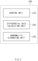
- FIG. 2 is a block diagram showing a structure of a battery abnormality diagnosis apparatus according to an embodiment of the present invention.
- a battery abnormality diagnosis apparatus 200 may include a sensing unit 210, a differential data calculating unit 220, and an abnormality diagnosing unit 230.
- the sensing unit 210 may measure a voltage and a current of the battery cell.
- the sensing unit 210 may measure the voltage and the current of the battery cell at specific time intervals.
- the differential data calculating unit 220 may calculate differential data for the capacity and the voltage of the battery cell. For example, the differential data calculating unit 220 may calculate a differential curve dQ/dV for the capacity and the voltage of the battery cell.
- the differential data calculating unit 220 may calculate differential data when a data value measured or calculated for the battery cell satisfies a preset condition. For example, the differential data calculating unit 220 may calculate differential data for the capacity and the voltage of the battery cell when a charging current change or a discharging current change of the battery cell for a specific time is greater than a reference value. Moreover, the differential data calculating unit 220 may calculate differential data for the capacity and the voltage of the battery cell when an State Of Charge (SOC) change for a specific time after end of charging/discharging of the battery cell is less than a reference value.
- SOC State Of Charge
- the differential data calculating unit 220 may calculate the differential data by using sampling with respect to voltage data measured through the sensing unit 210.
- sampling with respect to the voltage data may mean a pre-processing process of converting the voltage of the battery cell into data in a monotonically increasing or monotonically decreasing form.
- the differential data calculating unit 220 may perform sampling with respect to the voltage, by classifying capacity values Q of the battery cell, which have an equal voltage magnitude V, and calculating an average value of the capacity values of the battery cell for each voltage magnitude.
- the differential data calculating unit 220 may calculate the differential data by using a smoothing spline for the voltage data measured through the sensing unit 210. In this way, through conversion to satisfy continuity between adjacent data, a curve of the differential data of the battery cell may be converted into a gentle form.
- the abnormality diagnosing unit 230 may diagnose abnormality of the battery cell based on the differential data and classify a type of the abnormality.
- the abnormality diagnosing unit 230 may classify a type of the abnormality of the battery cell based on a peak value of the differential data.
- the abnormality diagnosing unit 230 may classify the type of the abnormality of the battery cell based on a voltage at a peak of the differential data and an intensity of the peak of the differential data.
- the abnormality diagnosing unit 230 may classify abnormality of the battery cell as a first type for the abnormality of the battery cell classify a first type for abnormality of the battery cell by comparing a sum of voltages at the peak of the differential data with a preset first reference value.
- the first reference value may be expressed as a sum of an average and a standard deviation for the differential data (e.g., ⁇ +3 ⁇ ).
- the first type for abnormality of the battery cell may include an available-lithium loss.
- the abnormality diagnosing unit 230 may classify abnormality of the battery cell as a second type for the abnormality of the battery cell by comparing a sum of intensities of peaks of the differential data with a preset second reference value.
- the second reference value may be expressed as a difference between the average and the standard deviation (e.g., ⁇ -3 ⁇ ).
- the second type for abnormality of the battery cell may include anodic reaction area reduction.
- the abnormality diagnosing unit 230 may classify abnormality of the battery cell as a third type for the abnormality of the battery cell by comparing a value, obtained by dividing an intensity of a peak of the differential data by a voltage at the peak of the differential data, with a preset third reference value.
- the third reference value may be expressed as a sum of the average and the standard deviation for the differential data (e.g., ⁇ +3 ⁇ ).
- the third type for abnormality of the battery cell may include cathodic reaction area reduction.
- the battery abnormality diagnosis apparatus 200 may include a storing unit.
- the storing unit may store voltage and current measurement data of the battery cell, differential data for the capacity and voltage of the battery cell, various data regarding an abnormality type of the battery cell, and the like.
- the storing unit is not necessarily included in the battery abnormality diagnosis apparatus 200, and the storing unit may be included in an external server and transmit and receive data through a separate communication module (not shown).
- the battery abnormality diagnosis apparatus 200 may further include a display unit.
- the battery abnormality diagnosis apparatus 200 may express a differential curve general shape, etc., calculated through the differential data calculating unit 220, in the form of a graph to a user through the display unit.
- the display unit may include a user interface (e.g., a touch pad, etc.) to receive a user's input.
- an abnormal behavior of the battery may be diagnosed and an abnormality type may be classified.
- FIG. 3 is a graph showing a general shape of differential data calculated by a battery abnormality diagnosis apparatus according to an embodiment of the present invention.
- an x axis may indicate a voltage V of a battery cell
- a y axis may indicate differential data dQ/dV (Ah/V) regarding a capacity and a voltage of the battery cell.
- the battery abnormality diagnosis apparatus may determine abnormality of the battery cell by analyzing a general shape of the differential data for the capacity and the voltage of the battery cell. For example, abnormality may occur in the battery cell in parts of a differential curve of FIG. 3 where peaks appear, like points Ea(1), Ea(5), Ec(2), and Ea(6) pre .
- abnormality of the battery cell may be diagnosed.
- a statistical value such as an average, a standard deviation, etc.
- a preset threshold value thereby detecting abnormality of the battery cell.
- an analysis scheme such as a sliding window for the average, the standard deviation, etc.
- FIG. 4A is a view showing maximum peak voltage and peak intensity calculated by a battery abnormality diagnosis apparatus according to an embodiment of the present invention.
- an x axis indicates time and a y axis indicates a voltage V (e.g., the x axis of FIG. 3 ) where a maximum peak appears in the differential data of FIG. 3 .
- V e.g., the x axis of FIG. 3
- an x axis indicates time and a y axis indicates an intensity (Ah/V) of a maximum peak in the differential data of FIG. 3 .
- data of FIG. 4A which is obtained for a charging/discharging time of the battery cell, may correspond to Ea(5) and Ec(2) of FIG. 3 .
- the battery abnormality diagnosis apparatus may determine abnormality of the battery cell by detecting a peak value in a curve of a maximum peak voltage and a maximum peak intensity of the battery cell.
- FIG. 4B is a view showing a peak voltage and a peak intensity at a specific point in charging, calculated by a battery abnormality diagnosis apparatus according to an embodiment of the present invention.
- an x axis indicates time and a y axis indicates a voltage V (e.g., the x axis of FIG. 3 ) where a maximum peak appears in the differential data of FIG. 3 .
- V e.g., the x axis of FIG. 3
- an x axis indicates time and a y axis indicates an intensity (Ah/V) of a maximum peak in the differential data of FIG. 3 .
- data of FIG. 4B which is obtained for a charging/discharging time of the battery cell, may correspond to Ea(6) pre of FIG. 3 .
- the battery abnormality diagnosis apparatus may determine abnormality of the battery cell by detecting abnormal data deviating from a preset range from the curve of the maximum peak voltage and the maximum peak intensity of the battery cell.
- FIG. 5 is a view showing an abnormality type classified by a battery abnormality diagnosis apparatus according to an embodiment of the present invention.
- an x axis indicates an ID of a battery cell included in a battery rack
- a y axis indicates a sum of peak voltages at which a peak of differential data appears, a sum of intensities of peaks, and a value obtained by dividing an intensity of a peak by a voltage (e.g., Ea(6) pre of FIG. 3 ), respectively, sequentially in order from the left graph.
- the battery abnormality diagnosis apparatus may diagnose abnormality of the battery cell based on values calculated from the differential data and classify a type of the abnormality.
- abnormality of the battery cell when a sum of voltages at peaks of the differential data is greater than a first reference value (e.g., ⁇ +3 ⁇ ), abnormality of the battery cell may be classified as the first type for the abnormality of the battery cell.
- the first type may be an available-lithium loss.
- abnormality of the battery cell may be classified as the second type for the abnormality of the battery cell.
- the second type may be anodic reaction area reduction.
- abnormality of the battery cell may be classified as the third type for the abnormality of the battery cell.
- the third type may be cathodic reaction area reduction.
- the present invention is not limited thereto and an abnormality type detectable by the battery abnormality diagnosis apparatus according to the present invention may be included variously.
- a sum of voltages at peaks of the differential data, a sum of peak intensities of the differential data, and a value obtained by dividing a peak intensity of the differential data by a voltage at a peak of the differential data are compared with reference values
- the present invention is not limited thereto such that other calculated values derived from the differential data than the above-described calculated values may be used and various diagnosis schemes may be used depending on a need. While reference values have been set based on a sum of an average and a standard deviation for the differential data of the battery cell or a difference therebetween, the first through third reference values may be set variously depending on a need.
- FIG. 6 is a flowchart showing a battery abnormality diagnosis method according to an embodiment of the present invention.
- a voltage and a current of a battery cell may be measured in operation S610.
- the voltage and the current of the battery cell may be measured at preset specific time intervals.
- the preset condition may include a case where a charging current change or a discharging current change of the battery cell for a specific time is greater than a reference value and an SOC change for a specific time after end of charging/discharging of the battery cell is less than a reference value. This condition may be required for a stable operation of an ESS system.
- non-classification processing may be performed in operation S680.
- operation S630 may be performed.
- the differential data dQ/dV for the capacity and the voltage of the battery cell may be calculated.
- the differential data may be calculated.
- sampling with respect to a voltage may be performed by classifying capacity values having an equal voltage magnitude of the battery cell and calculating an average value of the capacity values of the battery cell for each voltage magnitude, such that the voltage of the battery cell may be converted into data in a monotonically increasing or monotonically decreasing form.
- the curve of the differential data of the battery cell may be converted into a gentle form.
- a voltage V peak at a peak of the differential data and an intensity Intensity of the peak of the differential data may be calculated, in operation S640.
- a sum, ⁇ V peak , of voltages at a peak of the differential data may be compared with a preset first reference value ( ⁇ +3 ⁇ ). When the sum of the voltages at the peak of the differential data exceeds the first reference value (YES), it is determined in operation S655 that an available-lithium loss occurs in the battery cell.
- a sum, ⁇ Intensity, of peak intensities of the differential data may be compared with a preset second reference value ( ⁇ -3 ⁇ ) in operation S660.
- ⁇ -3 ⁇ a preset second reference value
- a value, Intensity/V peak obtained by dividing a peak intensity of the differential data by a voltage at the peak of the differential data may be compared with a preset third reference value ( ⁇ +3 ⁇ ) in operation S670.
- YES the third reference value
- the process may end without classifying a type of abnormality of the battery cell, in operation S680.
- an abnormal behavior of the battery may be diagnosed and an abnormality type may be classified.
- FIG. 7 is a block diagram showing a hardware structure of a battery abnormality diagnosis apparatus according to an embodiment of the present invention.
- a battery abnormality diagnosis apparatus 700 may include a microcontroller unit (MCU) 710, a memory 720, an input/output interface (I/F) 730, and a communication I/F 740.
- MCU microcontroller unit
- I/F input/output interface
- the MCU 710 may be a processor that executes various programs (e.g., a battery diagnosis program, a differential data calculation program, a battery abnormality type classification program, etc.) stored in the memory 720, processes various data for abnormality diagnosis, type classification, etc., of the battery cell through these programs, and executes the above-described functions of FIG. 2 .
- programs e.g., a battery diagnosis program, a differential data calculation program, a battery abnormality type classification program, etc.
- the memory 720 may store various programs regarding differential data calculation, abnormality diagnosis and classification, etc., of the battery cell. Moreover, the memory 720 may store various data such as measured voltage and current data of the battery cell, differential data of the battery cell, etc.
- the memory 720 may be provided in plural, depending on a need.
- the memory 720 may be a volatile or nonvolatile memory.
- RAM random access memory
- DRAM dynamic RAM
- SRAM static RAM
- ROM read only memory
- PROM programmable ROM
- EAROM electrically alterable ROM
- EPROM erasable PROM
- EEPROM electrically erasable PROM
- flash memory etc.
- the above-listed examples of the memory 720 are merely examples and are not limited thereto.
- the input/output I/F 730 may provide an interface for transmitting and receiving data by connecting an input device (not shown) such as a keyboard, a mouse, a touch panel, etc., and an output device such as a display (not shown), etc., with the MCU 710.
- an input device such as a keyboard, a mouse, a touch panel, etc.
- an output device such as a display (not shown), etc.
- the communication I/F 740 which is a component capable of transmitting and receiving various data to and from a server, may be various types of devices capable of supporting wired or wireless communication.
- a program for differential data calculation and diagnosis of the battery cell or various data may be transmitted and received to and from a separately provided external server through the communication I/F 740.
- a computer program according to an embodiment of the present invention may be recorded in the memory 720 and processed by the MCU 710, thus being implemented as a module that performs function blocks shown in FIG. 2 .
Landscapes
- Physics & Mathematics (AREA)
- General Physics & Mathematics (AREA)
- Engineering & Computer Science (AREA)
- Manufacturing & Machinery (AREA)
- Chemical & Material Sciences (AREA)
- Chemical Kinetics & Catalysis (AREA)
- Electrochemistry (AREA)
- General Chemical & Material Sciences (AREA)
- Power Engineering (AREA)
- Secondary Cells (AREA)
- Tests Of Electric Status Of Batteries (AREA)
Abstract
Description
- This application claims priority to and the benefit of
Korean Patent Application No. 10-2020-0100130 filed in the Korean Intellectual Property Office on August 10, 2020 - The present invention relates to a battery abnormality diagnosis apparatus and method for diagnosing an abnormal behavior of a battery by using a differential curve for a capacity-voltage of the battery and classifying an abnormality type.
- Recently, research and development of secondary batteries have been actively performed. Herein, the secondary batteries, which are chargeable/dischargeable batteries, may include all of conventional nickel (Ni)/cadmium (Cd) batteries, Ni/metal hydride (MH) batteries, etc., and recent lithium ion batteries. Among the secondary batteries, a lithium ion battery has a much higher energy density than those of the conventional Ni/Cd batteries, Ni/MH batteries, etc. Moreover, the lithium ion battery may be manufactured to be small and lightweight, such that the lithium ion battery has been used as a power source of mobile devices. In addition, the lithium ion battery is attracting attention as a next-generation energy storage medium as a usage range thereof is expanded to a power source of electric vehicles.
- Furthermore, the secondary battery is generally used as a battery pack including a battery module where a plurality of battery cells are connected to one another in series and/or in parallel. The battery pack may be managed and controlled by a battery management system in terms of a state and an operation.
- When such a secondary battery is continuously used, a degradation phenomenon may occur in which an available capacity of the battery gradually decreases. Conventionally, detection of an unstable behavior of measurement data has been detected to detect degradation of the battery, but there is no way to detect degradation when the battery operates normally. Moreover, conventionally, degradation of the battery is merely detected, but a detailed type of degradation is difficult to identify.
- The present invention has been designed to solve the foregoing problems and aims to provide a battery abnormality diagnosis apparatus and method in which by analyzing differential data for a capacity and a voltage of a battery, an abnormal behavior of the battery is diagnosed and an abnormality type is classified.
- A battery abnormality diagnosis apparatus according to an embodiment of the present invention includes a sensing unit measuring a voltage and a current of a battery cell, a differential data calculating unit calculating differential data for a capacity and the voltage of the battery cell, and an abnormality diagnosing unit diagnosing abnormality of the battery cell based on the differential data and classifying a type of the abnormality.
- A battery abnormality diagnosis method according to an embodiment of the present invention includes measuring a voltage and a current of a battery cell, calculating differential data for a capacity and the voltage of the battery cell, and diagnosing abnormality of the battery cell based on the differential data and classifying a type of the abnormality.
- According to the battery abnormality diagnosis apparatus and method of the present invention, by analyzing differential data for a capacity and a voltage of a battery, an abnormal behavior of the battery may be diagnosed and an abnormality type may be classified.
-
-
FIG. 1 is a block diagram of a general battery Rack. -
FIG. 2 is a block diagram showing a structure of a battery abnormality diagnosis apparatus according to an embodiment of the present invention. -
FIG. 3 is a graph showing a general shape of differential data calculated by a battery abnormality diagnosis apparatus according to an embodiment of the present invention. -
FIG. 4A is a view showing maximum peak voltage and peak intensity calculated by a battery abnormality diagnosis apparatus according to an embodiment of the present invention. -
FIG. 4B is a view showing a peak voltage and a peak intensity at a specific point in charging, calculated by a battery abnormality diagnosis apparatus, according to an embodiment of the present invention. -
FIG. 5 is a view showing an abnormality type classified by a battery abnormality diagnosis apparatus according to an embodiment of the present invention. -
FIG. 6 is a flowchart showing a battery abnormality diagnosis method according to an embodiment of the present invention. -
FIG. 7 is a block diagram showing a hardware structure of a battery abnormality diagnosis apparatus according to an embodiment of the present invention. - Hereinafter, various embodiments of the present invention will be described in detail with reference to the accompanying drawings. In this document, identical reference numerals will be used for identical components in the drawings, and the identical components will not be redundantly described.
- For various embodiments of the present invention disclosed in this document, specific structural or functional descriptions are only exemplified for the purpose of describing the embodiments of the present invention, and various embodiments of the present invention may be implemented in various forms, and should not be construed as being limited to the embodiments described in this document.
- As used in various embodiments, the terms "1st, "2nd", "first", "second", or the like may modify various components regardless of order and/or importance, and do not limit the components. For example, a first component may be named as a second component without departing from the right scope of the present disclosure, and similarly, the second component may be named as the first component.
- Terms used in the present document are used for only describing a specific exemplary embodiment of the disclosure and may not have an intention to limit the scope of other exemplary embodiments of the disclosure. It is to be understood that the singular expressions include plural expressions unless the context clearly dictates otherwise.
- All of the terms used herein including technical or scientific terms have the same meanings as those generally understood by an ordinary skilled person in the related art. It will be further understood that terms, such as those defined in commonly used dictionaries, should be interpreted as having a meaning that is consistent with their meaning in the context of the relevant art and will not be interpreted in an idealized or overly formal sense unless expressly so defined herein. In some cases, the terms defined herein may be interpreted to exclude embodiments of the present disclosure.
-
FIG. 1 is a block diagram of a general battery rack. - Referring to
FIG. 1 , a battery control system including abattery rack 1 and a higher-level controller 2 included in a higher-level system according to an embodiment of the present invention is schematically shown. - As shown in
FIG. 1 , thebattery rack 1 may include abattery module 10 that includes one or more battery cells and is chargeable/dischargeable, aswitching unit 14 serially connected to a positive (+) terminal side or a negative (-) terminal side of thebattery module 10 to control a charging/discharging current flow of thebattery module 10, and a battery management system (e.g., MBMS) 20 for control and management to prevent over-charging and over-discharging by monitoring voltage, current, temperature, etc., of thebattery rack 1. Thebattery rack 1 may include a plurality ofbattery modules 10,sensors 12,switching units 14, andbattery management systems 20. - Herein, as the
switching unit 14 which is a semiconductor switching element for controlling a current flow for charging or discharging of the plurality ofbattery modules 10, for example, at least one Metal Oxide Semiconductor Field Effect Transistor (MOSFET), relay, magnetic contactor, etc., may be used according to specifications of thebattery rack 1. - The
battery management system 20 may measure or calculate voltage and current of a gate, a source, a drain, etc., of the semiconductor switching element to monitor voltage, current, temperature, etc., of thebattery rack 1. Thebattery management system 20 may measure current, voltage, temperature, etc., of thebattery rack 1 by using asensor 12 provided adjacent to the semiconductor switching element. Herein, thesensor 12 may correspond to a sensing unit ofFIG. 2 described below. - The
battery management system 20, which is an interface for receiving measurement values of the above-described various parameters, may include a plurality of terminals and a circuit, etc., connected thereto to process input values. Thebattery management system 20 may control ON/OFF of theswitching unit 14, e.g., the MOSFET, and may be connected to thebattery module 10 to monitor a state of eachbattery module 10. - Meanwhile, the
battery management system 20 according to the present invention may calculate differential data for a capacity and a voltage of a battery cell through a separate program, as will be described below. Abnormality of the battery cell may be diagnosed using calculated differential data. - The higher-
level controller 2 may transmit a control signal for thebattery module 10 to thebattery management system 20. Thus, thebattery management system 20 may also be controlled in terms of an operation thereof based on a signal applied from the higher-level controller 2. Meanwhile, the battery cell according to the present invention may be included in thebattery module 10 used for an energy storage system (ESS). In this case, the higher-level controller 2 may be an ESS controller. However, thebattery rack 1 is not limited to such a purpose. - Such configurations of the
battery rack 1 and thebattery management system 20 are well-known configurations, and thus will not be described in detail. -
FIG. 2 is a block diagram showing a structure of a battery abnormality diagnosis apparatus according to an embodiment of the present invention. - Referring to
FIG. 2 , a batteryabnormality diagnosis apparatus 200 according to an embodiment of the present invention may include asensing unit 210, a differentialdata calculating unit 220, and anabnormality diagnosing unit 230. - The
sensing unit 210 may measure a voltage and a current of the battery cell. Thesensing unit 210 may measure the voltage and the current of the battery cell at specific time intervals. - The differential
data calculating unit 220 may calculate differential data for the capacity and the voltage of the battery cell. For example, the differentialdata calculating unit 220 may calculate a differential curve dQ/dV for the capacity and the voltage of the battery cell. - In this case, the differential
data calculating unit 220 may calculate differential data when a data value measured or calculated for the battery cell satisfies a preset condition. For example, the differentialdata calculating unit 220 may calculate differential data for the capacity and the voltage of the battery cell when a charging current change or a discharging current change of the battery cell for a specific time is greater than a reference value. Moreover, the differentialdata calculating unit 220 may calculate differential data for the capacity and the voltage of the battery cell when an State Of Charge (SOC) change for a specific time after end of charging/discharging of the battery cell is less than a reference value. Such conditions may be required for a stable operation of an ESS system. - The differential
data calculating unit 220 may calculate the differential data by using sampling with respect to voltage data measured through thesensing unit 210. Herein, sampling with respect to the voltage data may mean a pre-processing process of converting the voltage of the battery cell into data in a monotonically increasing or monotonically decreasing form. For example, the differentialdata calculating unit 220 may perform sampling with respect to the voltage, by classifying capacity values Q of the battery cell, which have an equal voltage magnitude V, and calculating an average value of the capacity values of the battery cell for each voltage magnitude. - In addition, the differential
data calculating unit 220 may calculate the differential data by using a smoothing spline for the voltage data measured through thesensing unit 210. In this way, through conversion to satisfy continuity between adjacent data, a curve of the differential data of the battery cell may be converted into a gentle form. - The
abnormality diagnosing unit 230 may diagnose abnormality of the battery cell based on the differential data and classify a type of the abnormality. Theabnormality diagnosing unit 230 may classify a type of the abnormality of the battery cell based on a peak value of the differential data. Moreover, theabnormality diagnosing unit 230 may classify the type of the abnormality of the battery cell based on a voltage at a peak of the differential data and an intensity of the peak of the differential data. - More specifically, the
abnormality diagnosing unit 230 may classify abnormality of the battery cell as a first type for the abnormality of the battery cell classify a first type for abnormality of the battery cell by comparing a sum of voltages at the peak of the differential data with a preset first reference value. In this case, the first reference value may be expressed as a sum of an average and a standard deviation for the differential data (e.g., µ+3σ). For example, the first type for abnormality of the battery cell may include an available-lithium loss. - Furthermore, the
abnormality diagnosing unit 230 may classify abnormality of the battery cell as a second type for the abnormality of the battery cell by comparing a sum of intensities of peaks of the differential data with a preset second reference value. In this case, the second reference value may be expressed as a difference between the average and the standard deviation (e.g., µ-3σ). For example, the second type for abnormality of the battery cell may include anodic reaction area reduction. - The
abnormality diagnosing unit 230 may classify abnormality of the battery cell as a third type for the abnormality of the battery cell by comparing a value, obtained by dividing an intensity of a peak of the differential data by a voltage at the peak of the differential data, with a preset third reference value. In this case, the third reference value may be expressed as a sum of the average and the standard deviation for the differential data (e.g., µ+3σ). For example, the third type for abnormality of the battery cell may include cathodic reaction area reduction. - Meanwhile, although not shown in
FIG. 2 , the batteryabnormality diagnosis apparatus 200 according to an embodiment of the present invention may include a storing unit. The storing unit may store voltage and current measurement data of the battery cell, differential data for the capacity and voltage of the battery cell, various data regarding an abnormality type of the battery cell, and the like. However, the storing unit is not necessarily included in the batteryabnormality diagnosis apparatus 200, and the storing unit may be included in an external server and transmit and receive data through a separate communication module (not shown). - The battery
abnormality diagnosis apparatus 200 according to an embodiment of the present invention may further include a display unit. Thus, the batteryabnormality diagnosis apparatus 200 according to an embodiment of the present invention may express a differential curve general shape, etc., calculated through the differentialdata calculating unit 220, in the form of a graph to a user through the display unit. In addition, the display unit may include a user interface (e.g., a touch pad, etc.) to receive a user's input. - As such, according to the battery abnormality diagnosis apparatus and method of the present invention, by analyzing differential data for a capacity and a voltage of a battery, an abnormal behavior of the battery may be diagnosed and an abnormality type may be classified.
-
FIG. 3 is a graph showing a general shape of differential data calculated by a battery abnormality diagnosis apparatus according to an embodiment of the present invention. Referring toFIG. 3 , an x axis may indicate a voltage V of a battery cell, and a y axis may indicate differential data dQ/dV (Ah/V) regarding a capacity and a voltage of the battery cell. - As shown in
FIG. 3 , the battery abnormality diagnosis apparatus according to an embodiment of the present invention may determine abnormality of the battery cell by analyzing a general shape of the differential data for the capacity and the voltage of the battery cell. For example, abnormality may occur in the battery cell in parts of a differential curve ofFIG. 3 where peaks appear, like points Ea(1), Ea(5), Ec(2), and Ea(6)pre. - Moreover, by applying a statistical method to the differential data of
FIG. 3 , abnormality of the battery cell may be diagnosed. For example, a statistical value such as an average, a standard deviation, etc., for the differential data of the battery cell may be compared with a preset threshold value, thereby detecting abnormality of the battery cell. In this case, by using an analysis scheme such as a sliding window for the average, the standard deviation, etc., abnormality may be diagnosed. -
FIG. 4A is a view showing maximum peak voltage and peak intensity calculated by a battery abnormality diagnosis apparatus according to an embodiment of the present invention. - Referring to
FIG. 4A , in an upper graph, an x axis indicates time and a y axis indicates a voltage V (e.g., the x axis ofFIG. 3 ) where a maximum peak appears in the differential data ofFIG. 3 . In a lower graph ofFIG. 4A , an x axis indicates time and a y axis indicates an intensity (Ah/V) of a maximum peak in the differential data ofFIG. 3 . In this case, data ofFIG. 4A , which is obtained for a charging/discharging time of the battery cell, may correspond to Ea(5) and Ec(2) ofFIG. 3 . - Referring to the upper graph and the lower graph of
FIG. 4A , the general shape of the maximum peak voltage and the maximum peak intensity of the battery cell has a peak that falls within a specific range and then leaves an upper end or a lower end during a specific period. For example, it may be seen fromFIG. 4A that peaks are generated in common in the upper graph and the lower graph on December 2, December 10, and December 26, 2019. Thus, the battery abnormality diagnosis apparatus according to an embodiment of the present invention may determine abnormality of the battery cell by detecting a peak value in a curve of a maximum peak voltage and a maximum peak intensity of the battery cell. -
FIG. 4B is a view showing a peak voltage and a peak intensity at a specific point in charging, calculated by a battery abnormality diagnosis apparatus according to an embodiment of the present invention. - Referring to
FIG. 4B , in an upper graph, an x axis indicates time and a y axis indicates a voltage V (e.g., the x axis ofFIG. 3 ) where a maximum peak appears in the differential data ofFIG. 3 . In a lower graph ofFIG. 4A , an x axis indicates time and a y axis indicates an intensity (Ah/V) of a maximum peak in the differential data ofFIG. 3 . In this case, data ofFIG. 4B , which is obtained for a charging/discharging time of the battery cell, may correspond to Ea(6)pre ofFIG. 3 . - Referring to an upper graph and a lower graph of
FIG. 4B , like in the case ofFIG. 4A , the general shape of the maximum peak voltage and the maximum peak intensity of the battery cell has data that falls within a specific range and then leaves an upper end or a lower end during a specific period. For example, abnormal data is generated on December 5, 2019 in the upper graph ofFIG. 4B , and abnormal data is generated on December 5, December 10, and December 13 in the lower graph. Thus, the battery abnormality diagnosis apparatus according to an embodiment of the present invention may determine abnormality of the battery cell by detecting abnormal data deviating from a preset range from the curve of the maximum peak voltage and the maximum peak intensity of the battery cell. -
FIG. 5 is a view showing an abnormality type classified by a battery abnormality diagnosis apparatus according to an embodiment of the present invention. - Referring to
FIG. 5 , an x axis indicates an ID of a battery cell included in a battery rack, and a y axis indicates a sum of peak voltages at which a peak of differential data appears, a sum of intensities of peaks, and a value obtained by dividing an intensity of a peak by a voltage (e.g., Ea(6)pre ofFIG. 3 ), respectively, sequentially in order from the left graph. - As such, as shown in
FIG. 5 , the battery abnormality diagnosis apparatus according to an embodiment of the present invention may diagnose abnormality of the battery cell based on values calculated from the differential data and classify a type of the abnormality. - More specifically, referring to the first graph of
FIG. 5 , when a sum of voltages at peaks of the differential data is greater than a first reference value (e.g., µ+3σ), abnormality of the battery cell may be classified as the first type for the abnormality of the battery cell. In this case, the first type may be an available-lithium loss. - In addition, referring to the second graph of
FIG. 5 , when a sum of peak intensities of the differential data is less than a preset second reference value (e.g., µ-3σ), abnormality of the battery cell may be classified as the second type for the abnormality of the battery cell. In this case, the second type may be anodic reaction area reduction. - Moreover, referring to the third graph of
FIG. 5 , when a value obtained by dividing a peak intensity of the differential data by a voltage at a peak of the differential data is greater than a preset third reference value (e.g., µ+3σ), abnormality of the battery cell may be classified as the third type for the abnormality of the battery cell. In this case, the third type may be cathodic reaction area reduction. - Meanwhile, it has been described with reference to
FIG. 5 that the first through third types for abnormality of the battery cell indicate the available-lithium loss, the anodic reaction area reduction, the cathodic reaction area reduction, respectively, the present invention is not limited thereto and an abnormality type detectable by the battery abnormality diagnosis apparatus according to the present invention may be included variously. - In addition, it has been described with reference to
FIG. 5 that a sum of voltages at peaks of the differential data, a sum of peak intensities of the differential data, and a value obtained by dividing a peak intensity of the differential data by a voltage at a peak of the differential data are compared with reference values, the present invention is not limited thereto such that other calculated values derived from the differential data than the above-described calculated values may be used and various diagnosis schemes may be used depending on a need. While reference values have been set based on a sum of an average and a standard deviation for the differential data of the battery cell or a difference therebetween, the first through third reference values may be set variously depending on a need. -
FIG. 6 is a flowchart showing a battery abnormality diagnosis method according to an embodiment of the present invention. - Referring to
FIG. 6 , a voltage and a current of a battery cell may be measured in operation S610. In this case, in operation S610, the voltage and the current of the battery cell may be measured at preset specific time intervals. - It is also determined in operation S620 whether measurement data values satisfy a preset condition. Herein, the preset condition may include a case where a charging current change or a discharging current change of the battery cell for a specific time is greater than a reference value and an SOC change for a specific time after end of charging/discharging of the battery cell is less than a reference value. This condition may be required for a stable operation of an ESS system.
- When the measurement data value does not satisfy the preset condition (NO), non-classification processing may be performed in operation S680. On the other hand, when the measurement data value satisfies a preset condition (YES), operation S630 may be performed.
- In operation S630, the differential data dQ/dV for the capacity and the voltage of the battery cell may be calculated. In this case, by using sampling with respect to measured voltage data, the differential data may be calculated. For example, sampling with respect to a voltage may be performed by classifying capacity values having an equal voltage magnitude of the battery cell and calculating an average value of the capacity values of the battery cell for each voltage magnitude, such that the voltage of the battery cell may be converted into data in a monotonically increasing or monotonically decreasing form. In operation S630, through conversion using a smoothing spline with respect to the measured voltage data to satisfy continuity between adjacent data, the curve of the differential data of the battery cell may be converted into a gentle form.
- Next, a voltage Vpeak at a peak of the differential data and an intensity Intensity of the peak of the differential data may be calculated, in operation S640. In operation S650, a sum, ΣVpeak, of voltages at a peak of the differential data may be compared with a preset first reference value (µ+3σ). When the sum of the voltages at the peak of the differential data exceeds the first reference value (YES), it is determined in operation S655 that an available-lithium loss occurs in the battery cell.
- On the other hand, when the sum of the voltages at the peak of the differential data is less than or equal to a second reference value (NO), a sum, ΣIntensity, of peak intensities of the differential data may be compared with a preset second reference value (µ-3σ) in operation S660. When the sum of the peak intensities of the differential data is less than the second reference value (YES), it is determined in operation S665 that anodic reaction area reduction occurs in the battery cell.
- On the other hand, when the sum of the peak intensities of the differential data is greater than or equal to the second reference value (NO), a value, Intensity/Vpeak, obtained by dividing a peak intensity of the differential data by a voltage at the peak of the differential data may be compared with a preset third reference value (µ+3σ) in operation S670. When the sum of the peak intensities of the differential data is greater than the third reference value (YES), it is determined in operation S675 that cathodic reaction area reduction occurs in the battery cell.
- Meanwhile, when the sum of the peak intensities of the differential data is less than the third reference value (NO), the process may end without classifying a type of abnormality of the battery cell, in operation S680.
- As such, according to the battery abnormality diagnosis method of the present invention, by analyzing differential data for a capacity and a voltage of a battery, an abnormal behavior of the battery may be diagnosed and an abnormality type may be classified.
-
FIG. 7 is a block diagram showing a hardware structure of a battery abnormality diagnosis apparatus according to an embodiment of the present invention. - Referring to
FIG. 7 , a batteryabnormality diagnosis apparatus 700 according to an embodiment of the present invention may include a microcontroller unit (MCU) 710, amemory 720, an input/output interface (I/F) 730, and a communication I/F 740. - The
MCU 710 may be a processor that executes various programs (e.g., a battery diagnosis program, a differential data calculation program, a battery abnormality type classification program, etc.) stored in thememory 720, processes various data for abnormality diagnosis, type classification, etc., of the battery cell through these programs, and executes the above-described functions ofFIG. 2 . - The
memory 720 may store various programs regarding differential data calculation, abnormality diagnosis and classification, etc., of the battery cell. Moreover, thememory 720 may store various data such as measured voltage and current data of the battery cell, differential data of the battery cell, etc. - The
memory 720 may be provided in plural, depending on a need. Thememory 720 may be a volatile or nonvolatile memory. For thememory 720 as the volatile memory, random access memory (RAM), dynamic RAM (DRAM), static RAM (SRAM), etc., may be used. For thememory 720 as the nonvolatile memory, read only memory (ROM), programmable ROM (PROM), electrically alterable ROM (EAROM), erasable PROM (EPROM), electrically erasable PROM (EEPROM), flash memory, etc., may be used. The above-listed examples of thememory 720 are merely examples and are not limited thereto. - The input/output I/
F 730 may provide an interface for transmitting and receiving data by connecting an input device (not shown) such as a keyboard, a mouse, a touch panel, etc., and an output device such as a display (not shown), etc., with theMCU 710. - The communication I/
F 740, which is a component capable of transmitting and receiving various data to and from a server, may be various types of devices capable of supporting wired or wireless communication. For example, a program for differential data calculation and diagnosis of the battery cell or various data may be transmitted and received to and from a separately provided external server through the communication I/F 740. - As such, a computer program according to an embodiment of the present invention may be recorded in the
memory 720 and processed by theMCU 710, thus being implemented as a module that performs function blocks shown inFIG. 2 . - Even though all components constituting an embodiment of the present invention have been described above as being combined into one or operating in combination, the present invention is not necessarily limited to the embodiment. That is, within the object scope of the present invention, all the components may operate by being selectively combined into one or more.
- Moreover, terms such as "include", "constitute" or "have" described above may mean that the corresponding component may be inherent unless otherwise stated, and thus should be construed as further including other components rather than excluding other components. All terms including technical or scientific terms have the same meanings as those generally understood by those of ordinary skill in the art unless defined otherwise. The terms used generally like terms defined in dictionaries should be interpreted as having meanings that are the same as the contextual meanings of the relevant technology and should not be interpreted as having ideal or excessively formal meanings unless they are clearly defined in the present invention.
- The above description is merely illustrative of the technical idea of the present invention, and various modifications and variations will be possible without departing from the essential characteristics of the present invention by those of ordinary skill in the art to which the present invention pertains. Therefore, the embodiments disclosed in the present invention are intended for description rather than limitation of the technical spirit of the present invention, and the scope of the technical spirit of the present invention is not limited by these embodiments. The protection scope of the present invention should be interpreted by the following claims, and all technical spirits within the same range should be understood to be included in the range of the present invention.
Claims (18)
- A battery abnormality diagnosis apparatus, comprising:a sensing unit measuring a voltage and a current of a battery cell;a differential data calculating unit calculating differential data for a capacity and the voltage of the battery cell; andan abnormality diagnosing unit diagnosing abnormality of the battery cell based on the differential data and classifying a type of the abnormality.
- The battery abnormality diagnosis apparatus of claim 1, wherein the abnormality diagnosing unit classifies the type of the abnormality of the battery cell based on a peak value of the differential data.
- The battery abnormality diagnosis apparatus of claim 1, wherein the abnormality diagnosing unit classifies the type of the abnormality of the battery cell based on a voltage at a peak of the differential data and a peak intensity of the differential data.
- The battery abnormality diagnosis apparatus of claim 3, wherein the abnormality diagnosing unit classifies the abnormality of the battery cell as a first type of abnormality by comparing a sum of voltages at the peak of the differential data with a preset first reference value.
- The battery abnormality diagnosis apparatus of claim 4, wherein the first type of abnormality comprises an available-lithium loss.
- The battery abnormality diagnosis apparatus of claim 3, wherein the abnormality diagnosing unit classifies the abnormality of the battery cell as a second type of abnormality by comparing a sum of peak intensities of the differential data with a preset second reference value.
- The battery abnormality diagnosis apparatus of claim 6, wherein the second type of abnormality comprises an anodic reaction area reduction.
- The battery abnormality diagnosis apparatus of claim 3, wherein the abnormality diagnosing unit classifies the abnormality of the battery cell as a third type of abnormality by comparing a value obtained by dividing the peak intensity of the differential data by a voltage at the peak of the differential data with a preset third reference value.
- The battery abnormality diagnosis apparatus of claim 8, wherein the third type of abnormality comprises a cathodic reaction area reduction.
- The battery abnormality diagnosis apparatus of claim 1, wherein the differential data calculating unit calculates the differential data for the capacity and the voltage of the battery cell when a charging current change or a discharging current change of the battery cell for a specific time is greater than a reference value.
- The battery abnormality diagnosis apparatus of claim 1, wherein the differential data calculating unit calculates the differential data for the capacity and the voltage of the battery cell when a state of charge (SOC) change for a reference time after the end of charging/discharging of the battery cell is less than a reference value.
- The battery abnormality diagnosis apparatus of claim 1, wherein the differential data calculating unit calculates the differential data by using sampling with respect to voltage data measured through the sensing unit.
- The battery abnormality diagnosis apparatus of claim 1, wherein the differential data calculating unit calculates the differential data by using a smoothing spline with respect to voltage data measured through the sensing unit.
- A battery abnormality diagnosis method comprising:measuring a voltage and a current of a battery cell;calculating differential data for a capacity and a voltage of the battery cell; anddiagnosing abnormality of the battery cell based on the differential data and classifying a type of the abnormality.
- The battery abnormality diagnosis method of claim 14, wherein the classifying of the type of the abnormality of the battery cell is based on a peak value of the differential data.
- The battery abnormality diagnosis method of claim 14, wherein the classifying of the type of the abnormality of the battery cell is based on a voltage at a peak of the differential data and a peak intensity of the differential data.
- The battery abnormality diagnosis method of claim 14, wherein the classifying of the type of the abnormality of the battery cell includes comparing a sum of voltages at a peak of the differential data, a sum of peak intensities of the differential data, and a value obtained by dividing a magnitude of the differential data by a voltage at the peak of the differential data with a reference value.
- The battery abnormality diagnosis method of claim 14, wherein the type of the abnormality of the battery cell comprises at least one of an available-lithium loss, anodic reaction area reduction, and a cathodic reaction area reduction.
Applications Claiming Priority (2)
| Application Number | Priority Date | Filing Date | Title |
|---|---|---|---|
| KR1020200100130A KR102849365B1 (en) | 2020-08-10 | 2020-08-10 | Apparatus and method for diagnosing fault of battery |
| PCT/KR2021/010474 WO2022035151A1 (en) | 2020-08-10 | 2021-08-09 | Battery abnormality diagnosis device and method |
Publications (3)
| Publication Number | Publication Date |
|---|---|
| EP4134686A1 true EP4134686A1 (en) | 2023-02-15 |
| EP4134686A4 EP4134686A4 (en) | 2023-10-04 |
| EP4134686B1 EP4134686B1 (en) | 2025-05-28 |
Family
ID=80247434
Family Applications (1)
| Application Number | Title | Priority Date | Filing Date |
|---|---|---|---|
| EP21856157.9A Active EP4134686B1 (en) | 2020-08-10 | 2021-08-09 | Battery abnormality diagnosis apparatus and method |
Country Status (8)
| Country | Link |
|---|---|
| US (1) | US12130338B2 (en) |
| EP (1) | EP4134686B1 (en) |
| JP (1) | JP7501976B2 (en) |
| KR (1) | KR102849365B1 (en) |
| CN (1) | CN115552262B (en) |
| ES (1) | ES3034238T3 (en) |
| HU (1) | HUE071574T2 (en) |
| WO (1) | WO2022035151A1 (en) |
Families Citing this family (15)
| Publication number | Priority date | Publication date | Assignee | Title |
|---|---|---|---|---|
| CN114779104B (en) * | 2022-05-06 | 2025-05-09 | 阳光电源股份有限公司 | Energy storage system battery cell sampling fault diagnosis method and energy storage system |
| KR20230161075A (en) * | 2022-05-18 | 2023-11-27 | 주식회사 엘지에너지솔루션 | Battery status managing apparatus and operating method of the same |
| CN115015762B (en) * | 2022-05-24 | 2025-07-29 | 蜂巢能源科技股份有限公司 | Abnormal battery cell screening method, device and equipment based on pre-charging procedure |
| KR20230165067A (en) * | 2022-05-26 | 2023-12-05 | 주식회사 엘지에너지솔루션 | Apparatus and method for diagnosing battery |
| JP2025516737A (en) * | 2022-09-08 | 2025-05-30 | エルジー エナジー ソリューション リミテッド | Battery management device and method |
| JP7816120B2 (en) * | 2022-12-15 | 2026-02-18 | トヨタ自動車株式会社 | Method and program for diagnosing redundant power supply |
| EP4733785A1 (en) * | 2023-08-04 | 2026-04-29 | LG Energy Solution, Ltd. | Apparatus for diagnosing resistance property of unit cell, diagnosing method thereof, and unit cell for secondary battery satisfying specific condition according to method thereof |
| WO2025100910A1 (en) * | 2023-11-10 | 2025-05-15 | 주식회사 엘지에너지솔루션 | Battery management device and battery management method |
| CN117783872A (en) * | 2023-12-26 | 2024-03-29 | 北汽福田汽车股份有限公司 | Data anomaly detection method, device, server and storage medium for power battery |
| KR102757503B1 (en) * | 2024-02-08 | 2025-01-21 | 주식회사 엘지에너지솔루션 | Battery diagnostic device and method |
| US12223437B1 (en) | 2024-04-18 | 2025-02-11 | SB Technology, Inc. | Systems and methods for battery performance prediction |
| US12203993B1 (en) | 2024-04-18 | 2025-01-21 | SB Technology, Inc. | Diagnostic systems and methods for battery defect identification |
| KR20260026770A (en) * | 2024-08-20 | 2026-02-27 | 주식회사 엘지에너지솔루션 | Apparatus for barttery diagnose and method thereof |
| KR20260033800A (en) * | 2024-09-03 | 2026-03-10 | 주식회사 엘지에너지솔루션 | Battery inspection apparatus and battery inspection method |
| CN119199567B (en) * | 2024-11-27 | 2025-03-04 | 中通服节能技术服务有限公司 | Method, system and device for offline detection of battery capacity facing electric energy circulation |
Family Cites Families (34)
| Publication number | Priority date | Publication date | Assignee | Title |
|---|---|---|---|---|
| JP3459615B2 (en) * | 2000-05-30 | 2003-10-20 | 三洋電機株式会社 | Electrode for fuel cell and fuel cell |
| JP4919120B2 (en) * | 2009-03-03 | 2012-04-18 | 株式会社デンソー | Battery state detection device |
| DE102009002466A1 (en) * | 2009-04-17 | 2010-10-21 | Robert Bosch Gmbh | Extended battery diagnosis for traction batteries |
| WO2011007805A1 (en) * | 2009-07-17 | 2011-01-20 | 本田技研工業株式会社 | Monitoring system for lithium ion secondary cell and monitoring method for lithium ion secondary cell |
| US8653793B2 (en) | 2009-09-25 | 2014-02-18 | Toyota Jidosha Kabushiki Kaisha | Secondary battery system |
| JP2013247003A (en) | 2012-05-28 | 2013-12-09 | Sony Corp | Charge control device for secondary battery, charge control method for secondary battery, charged state estimation device for secondary battery, charged state estimation method for secondary battery, deterioration degree estimation device for secondary battery, deterioration degree estimation method for secondary battery, and secondary battery device |
| JP5662968B2 (en) | 2012-06-19 | 2015-02-04 | 株式会社日立製作所 | Secondary battery inspection system, charger / discharger, and inspection method |
| JP2015060761A (en) | 2013-09-19 | 2015-03-30 | 株式会社東芝 | Deterioration diagnostic system and deterioration diagnostic method of secondary battery |
| WO2015080285A1 (en) | 2013-11-29 | 2015-06-04 | 日立オートモティブシステムズ株式会社 | Battery module and assembled battery |
| CN103698714B (en) * | 2014-01-02 | 2016-06-29 | 清华大学 | Battery capacity decay mechanism discrimination method and system |
| JP6443656B2 (en) | 2014-07-02 | 2018-12-26 | パナソニックIpマネジメント株式会社 | Battery status judgment device |
| JP6488105B2 (en) | 2014-10-28 | 2019-03-20 | 株式会社東芝 | Storage battery evaluation apparatus and method |
| JP6485041B2 (en) | 2014-12-26 | 2019-03-20 | 株式会社リコー | Electric storage device deterioration estimation device, electric storage device deterioration estimation method, mobile object |
| JP2016126891A (en) | 2014-12-26 | 2016-07-11 | 株式会社東芝 | Power storage battery estimation device, power storage battery estimation method and program |
| JP6455313B2 (en) | 2015-05-21 | 2019-01-23 | 日産自動車株式会社 | Battery abnormality diagnosis device and abnormality diagnosis method |
| JP6500789B2 (en) | 2016-01-19 | 2019-04-17 | トヨタ自動車株式会社 | Control system of secondary battery |
| JP2017133870A (en) * | 2016-01-26 | 2017-08-03 | トヨタ自動車株式会社 | Device for detecting abnormal degradation of lithium ion secondary battery and method for detecting abnormal degradation |
| JP6607167B2 (en) | 2016-11-03 | 2019-11-20 | トヨタ自動車株式会社 | Inspection method for lithium ion secondary battery |
| US10547180B2 (en) * | 2016-11-04 | 2020-01-28 | Battelle Memorial Institute | Battery system management through non-linear estimation of battery state of charge |
| JP2018147635A (en) | 2017-03-03 | 2018-09-20 | 住友金属鉱山株式会社 | Evaluation method of positive electrode active material for secondary battery |
| KR20180130685A (en) * | 2017-05-30 | 2018-12-10 | 현대자동차주식회사 | Method for controlling operation of fuel cell |
| CN111448467B (en) * | 2017-07-24 | 2023-04-14 | 罗伯特·博世有限公司 | Method and system for modeling and estimating battery capacity |
| CN111448468B (en) * | 2017-08-18 | 2022-03-15 | 罗伯特·博世有限公司 | Method, device and system for detecting consistency of battery pack |
| US11226374B2 (en) * | 2017-10-17 | 2022-01-18 | The Board Of Trustees Of The Leland Stanford Junior University | Data-driven model for lithium-ion battery capacity fade and lifetime prediction |
| JP6981208B2 (en) | 2017-11-27 | 2021-12-15 | トヨタ自動車株式会社 | Battery deterioration judgment system |
| CN110462894B (en) | 2018-03-07 | 2024-05-24 | 株式会社博迈立铖 | Positive electrode active material for lithium ion secondary battery and lithium ion secondary battery |
| JP7141012B2 (en) | 2018-03-13 | 2022-09-22 | 三菱自動車工業株式会社 | Secondary battery system |
| KR102349300B1 (en) | 2018-04-10 | 2022-01-10 | 주식회사 엘지에너지솔루션 | Apparatus, method, battery pack and electrical system for determining electrode information of battery |
| US11598817B2 (en) | 2018-04-17 | 2023-03-07 | Mitsubishi Electric Corporation | Storage cell diagnostic device and storage cell diagnostic method, and storage cell control system |
| JP7185437B2 (en) | 2018-07-30 | 2022-12-07 | ビークルエナジージャパン株式会社 | BATTERY MANAGEMENT DEVICE, BATTERY MANAGEMENT METHOD, POWER STORAGE SYSTEM |
| CN109031153B (en) * | 2018-10-16 | 2020-01-24 | 北京交通大学 | Online health state estimation method for lithium ion battery |
| US11585859B2 (en) * | 2019-03-01 | 2023-02-21 | Chongqing Jinkang Powertrain New Energy Co., Ltd. | State of charge error estimation of battery cells background |
| FR3101429B1 (en) * | 2019-10-01 | 2021-09-24 | Powerup | Method for determining the state of health of a lithium-ion battery. |
| KR102943878B1 (en) | 2019-12-20 | 2026-03-26 | 주식회사 엘지에너지솔루션 | Apparatus and method for diagnosing battery |
-
2020
- 2020-08-10 KR KR1020200100130A patent/KR102849365B1/en active Active
-
2021
- 2021-08-09 HU HUE21856157A patent/HUE071574T2/en unknown
- 2021-08-09 CN CN202180034602.7A patent/CN115552262B/en active Active
- 2021-08-09 WO PCT/KR2021/010474 patent/WO2022035151A1/en not_active Ceased
- 2021-08-09 JP JP2022567855A patent/JP7501976B2/en active Active
- 2021-08-09 ES ES21856157T patent/ES3034238T3/en active Active
- 2021-08-09 EP EP21856157.9A patent/EP4134686B1/en active Active
- 2021-08-09 US US17/925,526 patent/US12130338B2/en active Active
Also Published As
| Publication number | Publication date |
|---|---|
| JP2023524846A (en) | 2023-06-13 |
| HUE071574T2 (en) | 2025-09-28 |
| ES3034238T3 (en) | 2025-08-14 |
| CN115552262B (en) | 2026-03-17 |
| KR20220019564A (en) | 2022-02-17 |
| JP7501976B2 (en) | 2024-06-18 |
| US20230194622A1 (en) | 2023-06-22 |
| KR102849365B1 (en) | 2025-08-25 |
| CN115552262A (en) | 2022-12-30 |
| US12130338B2 (en) | 2024-10-29 |
| WO2022035151A1 (en) | 2022-02-17 |
| EP4134686B1 (en) | 2025-05-28 |
| EP4134686A4 (en) | 2023-10-04 |
Similar Documents
| Publication | Publication Date | Title |
|---|---|---|
| EP4134686B1 (en) | Battery abnormality diagnosis apparatus and method | |
| EP3958006B1 (en) | Battery diagnosis apparatus and method | |
| KR102824599B1 (en) | Apparatus and method for diagnosing battery cell | |
| EP4155744B1 (en) | Battery abnormality diagnosis apparatus and method | |
| EP4040174B1 (en) | Apparatus and method for diagnosing battery | |
| EP4276483A1 (en) | Apparatus and method for battery management | |
| JP2022532545A (en) | Battery cell diagnostic device and method | |
| EP4235198B1 (en) | Battery management apparatus and method | |
| EP4484982B1 (en) | Battery diagnosing apparatus, battery diagnosing method, battery pack and electric vehicle | |
| EP4446760B1 (en) | Battery depth-of-charge calculation apparatus and operating method thereof | |
| EP4231026A1 (en) | Battery management device and method | |
| EP4675291A1 (en) | Battery management device and operating method thereof | |
| EP4567447A1 (en) | Battery management apparatus and operation method therefor | |
| EP4236013A1 (en) | Battery control system and method | |
| EP4692825A1 (en) | Battery management device and operation method thereof | |
| EP4726420A1 (en) | Battery management apparatus and operating method thereof | |
| EP4707836A1 (en) | Battery management apparatus and operating method thereof | |
| EP4707833A1 (en) | Battery management apparatus and operation method therefor | |
| EP4660650A1 (en) | Battery management apparatus and operating method thereof | |
| EP4481415A1 (en) | Battery management apparatus and operation method therefor | |
| KR20250097496A (en) | Battery management apparatus and operating method of the same | |
| EP4650803A1 (en) | Battery diagnosis device and operation method thereof | |
| KR20250010934A (en) | Battery management apparatus and operating method of the same |
Legal Events
| Date | Code | Title | Description |
|---|---|---|---|
| STAA | Information on the status of an ep patent application or granted ep patent |
Free format text: STATUS: THE INTERNATIONAL PUBLICATION HAS BEEN MADE |
|
| PUAI | Public reference made under article 153(3) epc to a published international application that has entered the european phase |
Free format text: ORIGINAL CODE: 0009012 |
|
| STAA | Information on the status of an ep patent application or granted ep patent |
Free format text: STATUS: REQUEST FOR EXAMINATION WAS MADE |
|
| 17P | Request for examination filed |
Effective date: 20221110 |
|
| AK | Designated contracting states |
Kind code of ref document: A1 Designated state(s): AL AT BE BG CH CY CZ DE DK EE ES FI FR GB GR HR HU IE IS IT LI LT LU LV MC MK MT NL NO PL PT RO RS SE SI SK SM TR |
|
| A4 | Supplementary search report drawn up and despatched |
Effective date: 20230905 |
|
| RIC1 | Information provided on ipc code assigned before grant |
Ipc: G01R 31/392 20190101ALI20230830BHEP Ipc: G01R 31/367 20190101ALI20230830BHEP Ipc: G01R 31/389 20190101ALI20230830BHEP Ipc: H01M 10/48 20060101ALI20230830BHEP Ipc: G01R 19/10 20060101ALI20230830BHEP Ipc: G01R 19/165 20060101ALI20230830BHEP Ipc: G01R 31/3842 20190101ALI20230830BHEP Ipc: G01R 31/396 20190101ALI20230830BHEP Ipc: G01R 31/36 20200101AFI20230830BHEP |
|
| DAV | Request for validation of the european patent (deleted) | ||
| DAX | Request for extension of the european patent (deleted) | ||
| GRAP | Despatch of communication of intention to grant a patent |
Free format text: ORIGINAL CODE: EPIDOSNIGR1 |
|
| STAA | Information on the status of an ep patent application or granted ep patent |
Free format text: STATUS: GRANT OF PATENT IS INTENDED |
|
| RIC1 | Information provided on ipc code assigned before grant |
Ipc: G01R 31/392 20190101ALI20240903BHEP Ipc: G01R 31/367 20190101ALI20240903BHEP Ipc: G01R 31/389 20190101ALI20240903BHEP Ipc: H01M 10/48 20060101ALI20240903BHEP Ipc: G01R 19/10 20060101ALI20240903BHEP Ipc: G01R 19/165 20060101ALI20240903BHEP Ipc: G01R 31/3842 20190101ALI20240903BHEP Ipc: G01R 31/396 20190101ALI20240903BHEP Ipc: G01R 31/36 20200101AFI20240903BHEP |
|
| INTG | Intention to grant announced |
Effective date: 20241008 |
|
| GRAS | Grant fee paid |
Free format text: ORIGINAL CODE: EPIDOSNIGR3 |
|
| GRAJ | Information related to disapproval of communication of intention to grant by the applicant or resumption of examination proceedings by the epo deleted |
Free format text: ORIGINAL CODE: EPIDOSDIGR1 |
|
| GRAL | Information related to payment of fee for publishing/printing deleted |
Free format text: ORIGINAL CODE: EPIDOSDIGR3 |
|
| STAA | Information on the status of an ep patent application or granted ep patent |
Free format text: STATUS: REQUEST FOR EXAMINATION WAS MADE |
|
| GRAP | Despatch of communication of intention to grant a patent |
Free format text: ORIGINAL CODE: EPIDOSNIGR1 |
|
| P01 | Opt-out of the competence of the unified patent court (upc) registered |
Free format text: CASE NUMBER: APP_65426/2024 Effective date: 20241211 |
|
| STAA | Information on the status of an ep patent application or granted ep patent |
Free format text: STATUS: GRANT OF PATENT IS INTENDED |
|
| INTC | Intention to grant announced (deleted) | ||
| INTG | Intention to grant announced |
Effective date: 20250116 |
|
| GRAA | (expected) grant |
Free format text: ORIGINAL CODE: 0009210 |
|
| STAA | Information on the status of an ep patent application or granted ep patent |
Free format text: STATUS: THE PATENT HAS BEEN GRANTED |
|
| AK | Designated contracting states |
Kind code of ref document: B1 Designated state(s): AL AT BE BG CH CY CZ DE DK EE ES FI FR GB GR HR HU IE IS IT LI LT LU LV MC MK MT NL NO PL PT RO RS SE SI SK SM TR |
|
| REG | Reference to a national code |
Ref country code: GB Ref legal event code: FG4D |
|
| REG | Reference to a national code |
Ref country code: CH Ref legal event code: EP |
|
| REG | Reference to a national code |
Ref country code: IE Ref legal event code: FG4D Ref country code: DE Ref legal event code: R096 Ref document number: 602021031516 Country of ref document: DE |
|
| REG | Reference to a national code |
Ref country code: ES Ref legal event code: FG2A Ref document number: 3034238 Country of ref document: ES Kind code of ref document: T3 Effective date: 20250814 |
|
| PGFP | Annual fee paid to national office [announced via postgrant information from national office to epo] |
Ref country code: HU Payment date: 20250827 Year of fee payment: 5 |
|
| REG | Reference to a national code |
Ref country code: HU Ref legal event code: AG4A Ref document number: E071574 Country of ref document: HU |
|
| REG | Reference to a national code |
Ref country code: NL Ref legal event code: MP Effective date: 20250528 |
|
| PG25 | Lapsed in a contracting state [announced via postgrant information from national office to epo] |
Ref country code: FI Free format text: LAPSE BECAUSE OF FAILURE TO SUBMIT A TRANSLATION OF THE DESCRIPTION OR TO PAY THE FEE WITHIN THE PRESCRIBED TIME-LIMIT Effective date: 20250528 |
|
| PGFP | Annual fee paid to national office [announced via postgrant information from national office to epo] |
Ref country code: ES Payment date: 20250911 Year of fee payment: 5 |
|
| PGFP | Annual fee paid to national office [announced via postgrant information from national office to epo] |
Ref country code: DE Payment date: 20250721 Year of fee payment: 5 |
|
| REG | Reference to a national code |
Ref country code: LT Ref legal event code: MG9D |
|
| PG25 | Lapsed in a contracting state [announced via postgrant information from national office to epo] |
Ref country code: NO Free format text: LAPSE BECAUSE OF FAILURE TO SUBMIT A TRANSLATION OF THE DESCRIPTION OR TO PAY THE FEE WITHIN THE PRESCRIBED TIME-LIMIT Effective date: 20250828 Ref country code: GR Free format text: LAPSE BECAUSE OF FAILURE TO SUBMIT A TRANSLATION OF THE DESCRIPTION OR TO PAY THE FEE WITHIN THE PRESCRIBED TIME-LIMIT Effective date: 20250829 |
|
| PG25 | Lapsed in a contracting state [announced via postgrant information from national office to epo] |
Ref country code: NL Free format text: LAPSE BECAUSE OF FAILURE TO SUBMIT A TRANSLATION OF THE DESCRIPTION OR TO PAY THE FEE WITHIN THE PRESCRIBED TIME-LIMIT Effective date: 20250528 Ref country code: PL Free format text: LAPSE BECAUSE OF FAILURE TO SUBMIT A TRANSLATION OF THE DESCRIPTION OR TO PAY THE FEE WITHIN THE PRESCRIBED TIME-LIMIT Effective date: 20250528 |
|
| PG25 | Lapsed in a contracting state [announced via postgrant information from national office to epo] |
Ref country code: BG Free format text: LAPSE BECAUSE OF FAILURE TO SUBMIT A TRANSLATION OF THE DESCRIPTION OR TO PAY THE FEE WITHIN THE PRESCRIBED TIME-LIMIT Effective date: 20250528 |
|
| PGFP | Annual fee paid to national office [announced via postgrant information from national office to epo] |
Ref country code: BE Payment date: 20250722 Year of fee payment: 5 Ref country code: GB Payment date: 20250722 Year of fee payment: 5 |
|
| PG25 | Lapsed in a contracting state [announced via postgrant information from national office to epo] |
Ref country code: HR Free format text: LAPSE BECAUSE OF FAILURE TO SUBMIT A TRANSLATION OF THE DESCRIPTION OR TO PAY THE FEE WITHIN THE PRESCRIBED TIME-LIMIT Effective date: 20250528 |
|
| PGFP | Annual fee paid to national office [announced via postgrant information from national office to epo] |
Ref country code: FR Payment date: 20250725 Year of fee payment: 5 Ref country code: AT Payment date: 20251020 Year of fee payment: 5 |
|
| PG25 | Lapsed in a contracting state [announced via postgrant information from national office to epo] |
Ref country code: RS Free format text: LAPSE BECAUSE OF FAILURE TO SUBMIT A TRANSLATION OF THE DESCRIPTION OR TO PAY THE FEE WITHIN THE PRESCRIBED TIME-LIMIT Effective date: 20250828 |
|
| PG25 | Lapsed in a contracting state [announced via postgrant information from national office to epo] |
Ref country code: IS Free format text: LAPSE BECAUSE OF FAILURE TO SUBMIT A TRANSLATION OF THE DESCRIPTION OR TO PAY THE FEE WITHIN THE PRESCRIBED TIME-LIMIT Effective date: 20250928 |
|
| PG25 | Lapsed in a contracting state [announced via postgrant information from national office to epo] |
Ref country code: LV Free format text: LAPSE BECAUSE OF FAILURE TO SUBMIT A TRANSLATION OF THE DESCRIPTION OR TO PAY THE FEE WITHIN THE PRESCRIBED TIME-LIMIT Effective date: 20250528 |
|
| REG | Reference to a national code |
Ref country code: AT Ref legal event code: MK05 Ref document number: 1798877 Country of ref document: AT Kind code of ref document: T Effective date: 20250528 |
|
| PG25 | Lapsed in a contracting state [announced via postgrant information from national office to epo] |
Ref country code: AT Free format text: LAPSE BECAUSE OF FAILURE TO SUBMIT A TRANSLATION OF THE DESCRIPTION OR TO PAY THE FEE WITHIN THE PRESCRIBED TIME-LIMIT Effective date: 20250528 Ref country code: SM Free format text: LAPSE BECAUSE OF FAILURE TO SUBMIT A TRANSLATION OF THE DESCRIPTION OR TO PAY THE FEE WITHIN THE PRESCRIBED TIME-LIMIT Effective date: 20250528 Ref country code: DK Free format text: LAPSE BECAUSE OF FAILURE TO SUBMIT A TRANSLATION OF THE DESCRIPTION OR TO PAY THE FEE WITHIN THE PRESCRIBED TIME-LIMIT Effective date: 20250528 |
|
| PG25 | Lapsed in a contracting state [announced via postgrant information from national office to epo] |
Ref country code: CZ Free format text: LAPSE BECAUSE OF FAILURE TO SUBMIT A TRANSLATION OF THE DESCRIPTION OR TO PAY THE FEE WITHIN THE PRESCRIBED TIME-LIMIT Effective date: 20250528 |
|
| PG25 | Lapsed in a contracting state [announced via postgrant information from national office to epo] |
Ref country code: EE Free format text: LAPSE BECAUSE OF FAILURE TO SUBMIT A TRANSLATION OF THE DESCRIPTION OR TO PAY THE FEE WITHIN THE PRESCRIBED TIME-LIMIT Effective date: 20250528 |
|
| PG25 | Lapsed in a contracting state [announced via postgrant information from national office to epo] |
Ref country code: SK Free format text: LAPSE BECAUSE OF FAILURE TO SUBMIT A TRANSLATION OF THE DESCRIPTION OR TO PAY THE FEE WITHIN THE PRESCRIBED TIME-LIMIT Effective date: 20250528 |
|
| PG25 | Lapsed in a contracting state [announced via postgrant information from national office to epo] |
Ref country code: IT Free format text: LAPSE BECAUSE OF FAILURE TO SUBMIT A TRANSLATION OF THE DESCRIPTION OR TO PAY THE FEE WITHIN THE PRESCRIBED TIME-LIMIT Effective date: 20250528 |
|
| REG | Reference to a national code |
Ref country code: DE Ref legal event code: R097 Ref document number: 602021031516 Country of ref document: DE |
|
| PG25 | Lapsed in a contracting state [announced via postgrant information from national office to epo] |
Ref country code: RO Free format text: LAPSE BECAUSE OF FAILURE TO SUBMIT A TRANSLATION OF THE DESCRIPTION OR TO PAY THE FEE WITHIN THE PRESCRIBED TIME-LIMIT Effective date: 20250528 |
|
| REG | Reference to a national code |
Ref country code: CH Ref legal event code: H13 Free format text: ST27 STATUS EVENT CODE: U-0-0-H10-H13 (AS PROVIDED BY THE NATIONAL OFFICE) Effective date: 20260324 |
|
| PG25 | Lapsed in a contracting state [announced via postgrant information from national office to epo] |
Ref country code: MC Free format text: LAPSE BECAUSE OF FAILURE TO SUBMIT A TRANSLATION OF THE DESCRIPTION OR TO PAY THE FEE WITHIN THE PRESCRIBED TIME-LIMIT Effective date: 20250528 |
|
| PLBE | No opposition filed within time limit |
Free format text: ORIGINAL CODE: 0009261 |
|
| STAA | Information on the status of an ep patent application or granted ep patent |
Free format text: STATUS: NO OPPOSITION FILED WITHIN TIME LIMIT |
|
| REG | Reference to a national code |
Ref country code: CH Ref legal event code: L10 Free format text: ST27 STATUS EVENT CODE: U-0-0-L10-L00 (AS PROVIDED BY THE NATIONAL OFFICE) Effective date: 20260409 |
|
| PG25 | Lapsed in a contracting state [announced via postgrant information from national office to epo] |
Ref country code: LU Free format text: LAPSE BECAUSE OF NON-PAYMENT OF DUE FEES Effective date: 20250809 |
|
| PG25 | Lapsed in a contracting state [announced via postgrant information from national office to epo] |
Ref country code: CH Free format text: LAPSE BECAUSE OF NON-PAYMENT OF DUE FEES Effective date: 20250831 |