EP4134622B1 - Antriebs- und erfassungsausgeglichenes, vollständig gekoppeltes dreiachsiges gyroskop - Google Patents
Antriebs- und erfassungsausgeglichenes, vollständig gekoppeltes dreiachsiges gyroskop Download PDFInfo
- Publication number
- EP4134622B1 EP4134622B1 EP22196652.6A EP22196652A EP4134622B1 EP 4134622 B1 EP4134622 B1 EP 4134622B1 EP 22196652 A EP22196652 A EP 22196652A EP 4134622 B1 EP4134622 B1 EP 4134622B1
- Authority
- EP
- European Patent Office
- Prior art keywords
- gyroscope
- proof masses
- exemplary
- axis
- inner frame
- Prior art date
- Legal status (The legal status is an assumption and is not a legal conclusion. Google has not performed a legal analysis and makes no representation as to the accuracy of the status listed.)
- Active
Links
Images


Classifications
-
- G—PHYSICS
- G01—MEASURING; TESTING
- G01C—MEASURING DISTANCES, LEVELS OR BEARINGS; SURVEYING; NAVIGATION; GYROSCOPIC INSTRUMENTS; PHOTOGRAMMETRY OR VIDEOGRAMMETRY
- G01C19/00—Gyroscopes; Turn-sensitive devices using vibrating masses; Turn-sensitive devices without moving masses; Measuring angular rate using gyroscopic effects
- G01C19/56—Turn-sensitive devices using vibrating masses, e.g. vibratory angular rate sensors based on Coriolis forces
- G01C19/5719—Turn-sensitive devices using vibrating masses, e.g. vibratory angular rate sensors based on Coriolis forces using planar vibrating masses driven in a translation vibration along an axis
- G01C19/5733—Structural details or topology
-
- G—PHYSICS
- G01—MEASURING; TESTING
- G01C—MEASURING DISTANCES, LEVELS OR BEARINGS; SURVEYING; NAVIGATION; GYROSCOPIC INSTRUMENTS; PHOTOGRAMMETRY OR VIDEOGRAMMETRY
- G01C19/00—Gyroscopes; Turn-sensitive devices using vibrating masses; Turn-sensitive devices without moving masses; Measuring angular rate using gyroscopic effects
- G01C19/56—Turn-sensitive devices using vibrating masses, e.g. vibratory angular rate sensors based on Coriolis forces
- G01C19/5705—Turn-sensitive devices using vibrating masses, e.g. vibratory angular rate sensors based on Coriolis forces using masses driven in reciprocating rotary motion about an axis
- G01C19/5712—Turn-sensitive devices using vibrating masses, e.g. vibratory angular rate sensors based on Coriolis forces using masses driven in reciprocating rotary motion about an axis the devices involving a micromechanical structure
-
- G—PHYSICS
- G01—MEASURING; TESTING
- G01C—MEASURING DISTANCES, LEVELS OR BEARINGS; SURVEYING; NAVIGATION; GYROSCOPIC INSTRUMENTS; PHOTOGRAMMETRY OR VIDEOGRAMMETRY
- G01C19/00—Gyroscopes; Turn-sensitive devices using vibrating masses; Turn-sensitive devices without moving masses; Measuring angular rate using gyroscopic effects
- G01C19/56—Turn-sensitive devices using vibrating masses, e.g. vibratory angular rate sensors based on Coriolis forces
- G01C19/5783—Mountings or housings not specific to any of the devices covered by groups G01C19/5607 - G01C19/5719
Definitions
- the present invention relates generally to angular velocity sensors and more particularly relates to angular velocity sensors that include guided mass systems.
- Vibratory rate gyroscopes broadly function by driving the sensor into a first motion and measuring a second motion of the sensor that is responsive to both the first motion and the angular velocity to be sensed.
- MEMS gyroscopes may not provide adequate solutions that reduce sensitivity to vibration and part-to-part coupling, reduce levitation force induced in-phase offset shift, and/or reduce sensitivity to package stress.
- Linear and angular momentum balanced 3-axis gyroscope architectures for better offset stability, vibration rejection, and lower part-to-part coupling are disclosed.
- a linear and angular momentum balanced 3-axis gyroscope architecture is described, which comprises one or more inner frame gyroscopes, two or more drive shuttles coupled to the one or more inner frame gyroscopes, two or more additional proof masses coupled to the inner frame gyroscopes, one or more outer frame gyroscope or saddle gyroscope coupled to the one or more inner frame gyroscopes, two outer frame lever arms associated with the outer frame gyroscope, and at least two drive shuttles, as defined in claim 1.
- Various embodiments described herein can facilitate providing linear and angular momentum balanced 3-axis gyroscope architectures for better offset stability, vibration rejection, and lower part-to-part coupling. Further non-limiting embodiments can be directed to methods associated with various embodiments described herein.
- EP 2 884 229 A1 relates to a gyroscope which comprises a substrate and a guided mass system.
- the guided mass system comprises proof masses and guiding arms disposed in a plane parallel to the substrate.
- the proof masses are coupled to the guiding arm by springs.
- the guiding arm is coupled to the substrate by springs.
- At least one of the proof-masses is directly coupled to the substrate by at least one anchor via a spring system.
- the gyroscope also comprises an actuator for vibrating one of the proof-masses in the first direction, which causes another proof mass to rotate in the plane.
- the gyroscope also includes transducers for sensing motion of the guided mass system in response to angular velocities about a single axis or multiple input axes.
- EP 2 339 293 A1 discusses an integrated MEMS gyroscope (1; 1'; 1") with: at least a first driving mass driven with a first driving movement along a first axis (x) upon biasing of an assembly of driving electrodes, the first driving movement generating at least one sensing movement, in the presence of rotations of the integrated MEMS gyroscope (1; 1'; 1"); and at least a second driving mass driven with a second driving movement along a second axis (y), transverse to the first axis (x), the second driving movement generating at least a respective sensing movement, in the presence of rotations of the integrated MEMS gyroscope (1; 1'; 1").
- the integrated MEMS gyroscope is moreover provided with a first elastic coupling element, which elastically couples the first driving mass and the second driving mass in such a way as to couple the first driving movement to the second driving movement with a given ratio of movement.
- MEMS microelectromechanical systems
- the present invention relates generally to angular velocity sensors and more particularly relates to angular velocity sensors that include guided mass systems.
- the following description is presented to enable one of ordinary skill in the art to make and use the invention and is provided in the context of a patent application and its requirements.
- Various modifications to the preferred embodiments and the generic principles and features described herein will be readily apparent to those skilled in the art.
- the present invention is not intended to be limited to the embodiments shown, but is to be accorded the widest scope consistent with the principles and features described herein. Accordingly, while a brief overview is provided, certain aspects of the subject disclosure are described or depicted herein for the purposes of illustration and not limitation. Thus, variations of the disclosed embodiments as suggested by the disclosed apparatuses, systems, and methodologies are intended to be encompassed within the scope of the subject matter disclosed herein.
- conventional MEMS vibratory rate gyroscopes may not provide adequate solutions that reduce sensitivity to vibration (e.g. , linear vibration and/or angular vibration) and part-to-part coupling, reduce levitation force induced in-phase offset shift, and/or reduce sensitivity to package stress.
- Various embodiments described herein can overcome one or more of these and/or related drawbacks of conventional MEMS vibratory rate gyroscopes.
- the subject disclosure provides exemplary 3-axis (e.g. , GX, GY, and GZ) linear and angular momentum balanced vibratory rate gyroscope architectures with fully-coupled sense modes.
- various exemplary embodiments can employ balanced drive and/or balanced sense components to reduce induced vibrations and/or part to part coupling, as described herein.
- various exemplary embodiments can employ a stress isolation frame to reduce package induced stress, as further described herein.
- various exemplary embodiments can employ mechanical coupling to facilitate linear vibration rejection.
- various exemplary embodiments can employ one or more drive shuttles to reject levitation force induced in-phase offset.
- various exemplary embodiments can facilitate fabrication of gyroscopes having improvements in cross-axis sensitivity due to decoupling of in-plane and out-of-plane gyroscopes, as described herein.
- exemplary embodiments can comprise two inner frame (e.g., GY) gyroscopes, wherein the inner frame gyroscopes facilitate GY sense mode and can facilitate drive system coupling, one outer frame (e .g.
- GX GX gyroscope
- the outer frame gyroscope facilitates GX sense mode and can facilitate drive system coupling, four drive shuttles coupled to the two inner frame gyroscopes or outer frame gyroscope, four GZ proof masses coupled to the inner frame gyroscopes, and/or coupling mechanisms that facilitate coupling GZ proof masses, coupling the inner frame gyroscopes, and/or facilitate coupling the inner frame gyroscopes with the outer frame gyroscope and/or drive shuttles.
- various exemplary embodiments can be configured such that components can be removed from an exemplary overall architecture to fabricate a single axis or two axis gyroscope and/or can be configured such that a number of proof-masses can be reduced in half from an exemplary overall architecture to fabricate a half-gyroscope, as further described herein.
- an exemplary 3-axis (e.g. , GX, GY, and GZ) gyroscope can be reduced to a 2-axis or 1-axis gyroscope by removing components from the architecture, employing fewer sense transducers, etc.
- exemplary gyroscope architectures as described herein can be functionally cut in half to create a more compact 3-axis (e.g. , GX, GY, and GZ, or fewer axes) gyroscope, by forgoing drive and/or sense balanced aspects of the exemplary 3-axis (e.g. , GX, GY, and GZ) gyroscope architectures.
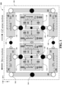
- FIG. 1 illustrates a functional block diagram of non-limiting embodiments of an exemplary gyroscope architecture 100, according to non-limiting aspects of the subject disclosure.
- exemplary embodiments of a gyroscope architecture 100 can comprise a MEMS device disposed in an X-Y plane parallel to a substrate 102 and can comprise two inner frame (e.g. , GY) gyroscopes, that can each comprise two inner frame proof masses (e.g.
- exemplary embodiments of a gyroscope architecture 100 can comprise a coupling mechanism that couples the two inner frame ( e.g. , GY) gyroscopes to each other.
- exemplary embodiments of a gyroscope architecture 100 can comprise a drive system comprising four drive shuttles (not shown), comprising guided masses and configured to be coupled to the two inner frame gyroscopes, respectively.
- exemplary gyroscope architecture 100 can comprise four GZ proof masses (e.g. , GZ proof masses 120, 122, 124, 126), configured to be coupled to each other via coupling mechanisms 128 and 130 ( e.g. , via a spring and/or other coupling structures), respectively, wherein respective pairs of the four GZ proof masses (e.g. , GZ proof masses 120, 122, 124, 126) are coupled to each other via coupling mechanisms or lever arms 128, 130 that are configured to couple the respective pairs of the four proof masses (e.g. , GZ proof masses 120, 122, 124, 126) motions, and wherein the four GZ proof masses (e.g.
- GZ proof masses 120, 122, 124, 126) can be configured to facilitate providing a GZ sense mode, or measuring a component of angular velocity associated with the MEMS device around another axis ( e.g. , Z axis).
- exemplary gyroscope architecture 100 can comprise an outer frame or saddle (e.g. , GX) gyroscope ( e.g. , GX) that can comprise two outer frame gyroscopes, comprising two pairs of two proof masses (e.g.
- GX proof mass 132, 134, 136, 138 wherein the GX, outer frame, or saddle gyroscope can be configured to facilitate providing a GX sense mode, or measuring a component of angular velocity associated with the MEMS device around another axis ( e.g. , X axis), can be configured to be coupled to the inner frame gyroscopes, respectively, and can be configured to couple the drive system with the outer frame gyroscopes, wherein respective pairs of two GX proof masses (e.g. , GX proof mass 132/134, 136/138)can be configured to be coupled to each other, and wherein respective GX proof masses of the pairs ( e.g. , GX proof mass 132/134, 136/138) can be configured to be coupled to each other via respective outer frame lever arms 140/142.
- respective pairs of two GX proof masses e.g. , GX proof mass 132/134, 136/138
- respective GX proof masses of the pairs e.
- exemplary gyroscope architecture 100 can comprise exemplary anchor points (e.g. , depicted herein as rectangles with an X), which can facilitate anchoring various components to the substrate 102 and/or to an exemplary stress isolation frame (not shown) configured to be attached to the substrate 102 or package.
- exemplary gyroscope architecture 100 of FIG. 1 is depicted comprising exemplary fixed pivot points 144 ( e.g. , black-filled circles), which can functionally represent a center about which various components can be configured to rotate ( e.g.
- exemplary translating pivot points 146 e.g. , white-filled circles
- exemplary translating pivot points 146 can functionally represent a pivot point or hinge about which various components can be configured to rotate and translate ( e.g. , in a plane parallel to the X-Y plane of the substrate 102, in a plane orthogonal to the X-Y plane of the substrate 102, etc. ).
- pivot points can be understood to be a functional representation of the centers of rotational motions as a result of the processes required to create such devices via MEMS fabrication, which typically comprise a set of springs, flexures, rigid bodies, or suspension mechanisms or components arranged to produce the desired motion, as further described herein.
- exemplary gyroscope architecture 100 of FIG. 1 is depicted comprising exemplary springs (e.g. , spring 145), suspension elements, or coupling mechanisms, which can comprise flexures or other structures that are particularly rigid, or flexibly and/or torsionally compliant in particular directions to constrain or define motions ( e.g. , to anti-phase motion, to in-plane motion, to guide mass motions of guided masses, etc. ) and/or transfer motions of the various components of exemplary gyroscope architecture 100, suspend various components of exemplary gyroscope architecture 100 to exemplary anchor points 302, for example, as depicted in FIG. 3 , function as exemplary fixed pivot points 144 and/or exemplary translating pivot points 146, and so on, as further described herein.
- springs e.g. , spring 145
- suspension elements e.g. 145
- coupling mechanisms can comprise flexures or other structures that are particularly rigid, or flexibly and/or torsionally comp
- exemplary gyroscope architecture 100 of FIG. 1 is depicted as comprising an outer frame or saddle (e.g., GX) gyroscope (e.g. , GX, outer frame, or saddle gyroscope) that can comprise two GX outer frame gyroscopes, comprising two pairs of two proof masses (e.g. , GX proof mass 132, 134, 136, 138), wherein the GX, outer frame, or saddle gyroscope can be configured to be coupled to the inner frame gyroscopes (e.g.
- GX outer frame or saddle gyroscope
- exemplary GX, outer frame, or saddle gyroscope can be configured to be coupled to the inner frame gyroscopes ( e.g.
- respective pairs of the four exemplary GZ proof masses can be coupled to each other via coupling mechanisms or lever arms 128, 130 that are configured to coupled the respective pairs of the four proof masses (e.g. , GZ proof masses 120/122, 124/126) motions.
- exemplary GZ proof mass 120 is coupled to exemplary GZ proof mass 122 via coupling mechanisms or lever arm 128 and configured to force the respective pair of the four proof masses (e.g.
- exemplary GZ proof mass 120/122) into anti-phase motion, generally in an X-Y plane, parallel to exemplary substrate 102, as a result of a component of angular velocity associated with the MEMS device around the Z-axis.
- Such exemplary coupling is shown in FIG. 1 functionally as a rotation of coupling mechanisms or lever arm 128 about a fixed pivot point, centered on coupling mechanisms or lever arm 128, and is shown schematically in FIGS. 3-6 , for example.
- the two exemplary inner frame gyroscopes can be configured to be coupled to each other (e.g. , shown functionally via a spring coupling exemplary GY proof mass 106 to exemplary GY proof mass 108, such as shown schematically as spring 145 of FIG. 1 associated with GX proof mass 136) to facilitate constraining a motion associated with the two GY or inner frame gyroscopes into a condition of linear and angular momentum balance.
- exemplary GY proof mass 106 can be coupled to exemplary GY proof mass 108 via a spring or other structure or combination of structures that can facilitate constraining a motion associated with the two inner frame gyroscopes into a condition of linear and angular momentum balance, as further described herein.
- a spring or other structure or combination of structures that can facilitate constraining a motion associated with the two inner frame gyroscopes into a condition of linear and angular momentum balance, as further described herein.
- Such coupling is shown schematically in FIGS. 3-6 , for example.
- the two exemplary GX, or outer frame (saddle) gyroscopes, each comprising two proof masses e.g.
- GX proof mass 132, 134, 136, 138 can be coupled, respectively, to the two exemplary GY or inner frame gyroscopes, and/or can be configured to couple the two exemplary GX, outer frame, or saddle gyroscope to the four drive shuttles (not shown), as further described herein.
- FIG. 3 schematically, as the GY proof masses 108/110 (104/106) between GX proof masses 136 and 138 (132 and 134) ( e.g. , via springs, flexures, drive shuttles, lever arms 112, 114, 116, 118, etc.
- FIGS. 3-6 Such exemplary coupling is shown schematically in FIGS. 3-6 , for example.
- exemplary gyroscope architecture 100 of FIG. 1 is depicted comprising various sense electrodes or transducer elements, which can be respectively configured to detect motions of the various proof masses or other components of the exemplary gyroscope architecture 100, for example, to detect motions as a result of Coriolis forces induced on the various proof masses to provide a measure of the angular velocity about the X, Y, or Z axes, to detect drive motions, etc.
- electrostatic actuators and transducers are described throughout this specification, one of ordinary skill in the art recognizes that a variety of actuators and/or transducers could be utilized for these functions, and that use would be within the scope of the subject disclosure.
- exemplary actuators and/or transducers could comprise piezoelectric, thermal, electromagnetic, actuators and/or transducers, or the like.
- exemplary gyroscope architecture 100 can comprise capacitive electrodes 156, 158, 160, 162, configured to respectively detect motions of exemplary GX proof masses 132, 134, 136, 138, and can comprise capacitive electrodes 164, 166, 168, 170 configured to respectively detect motions of exemplary GY proof masses 104, 106, 108, 110, and so on.
- exemplary capacitive electrodes 156, 158, 160, 162, 164, 166, 168, 170 can be configured to primarily facilitate detection of Coriolis forces acting on respective proof masses as a result of angular velocity associated with the MEMS device about respective axes ( e.g. , X or Y axes). As further described herein, these Coriolis forces acting on respective proof masses as a result of angular velocity associated with the MEMS device about respective axes (e.g.
- out-of-plane motions of the respective proof masses can result in out-of-plane motions of the respective proof masses, wherein the out-of-plane motion is defined as motion in the direction of the Z axis ( e.g. , out of the X-Y plane).
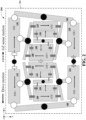
- exemplary gyroscope architecture 100 of FIG. 1 is depicted as undergoing drive motion in FIG. 2 , at a particular instance in time, which is indicated by a solid arrow in the direction of the respective various components of exemplary gyroscope architecture 100.
- an electrostatic force can be applied with exemplary drive combs (not shown) that can be coupled to exemplary drive shuttles (not shown), respectively, which exemplary drive shuttles can comprise the guided masses configured to be coupled to the two inner frame gyroscopes, the GX, outer frame, or saddle gyroscope, and/or combinations, or portions thereof, as described herein.
- an electrostatic force can be applied via the exemplary drive combs (not shown) to the exemplary drive shuttles (not shown) to generate the drive force at the drive frequency, which can result in the drive motions of the respective various components of exemplary gyroscope architecture 100 as indicated in FIG. 1 .
- This drive force applied to respective exemplary drive shuttles (not shown) is configured to be transferred to the various components of exemplary gyroscope architecture 100, via the above described coupling mechanisms, lever arms, pivot points, and springs, as described above, which results in the drive motions of the various components of exemplary gyroscope architecture 100, as depicted in FIG.
- FIG. 2 depicts deflection of various components of exemplary gyroscope architecture 100 as a result of a Coriolis force from angular velocity about the respective axes with the given direction of drive motion as positive (e.g. , GX+, GY+), or above the X-Y plane of the MEMS device, and as negative ( e.g. , GX-, GY-), or below the X-Y plane of the MEMS device.
- positive e.g. , GX+, GY+
- negative e.g. , GX-, GY-
- the four exemplary GZ proof masses (e.g. , GZ proof masses 120, 122, 124, 126) are configured to be coupled ( e.g. , via a spring or other coupling structure) to the four GY proof masses 104, 106, 108, 110, respectively, wherein respective pairs of the four GZ proof masses (e.g. , GZ proof masses 120, 122, 124, 126) are coupled to each other via coupling mechanisms or lever arms 128, 130 that are configured to couple the respective pairs of the four proof masses (e.g. , GZ proof masses 120, 122, 124, 126) motions.
- a Coriolis force acting on respective GZ proof masses e.g.
- GZ proof masses 120, 122, 124, 126) as a result of angular velocity associated with the MEMS device about the Z axis can result in motions of the respective GZ proof masses (e.g. , GZ proof masses 120, 122, 124, 126), generally in-plane, wherein the in-plane motion is defined as motion in the direction of the X axis ( e.g. , in the X-Y plane), as depicted.
- respective GZ proof masses (e.g. , GZ proof masses 120, 122, 124, 126) of exemplary gyroscope architecture 100 of FIG. 1 is depicted as experiencing a sensed motion, at a particular instance in time, which is indicated by a dashed arrow in the direction of the respective various components of exemplary gyroscope architecture 100 in FIG. 2 .
- exemplary gyroscope architecture 100 can comprise further capacitive electrodes (not shown) that can be configured to respectively detect motions of respective GZ proof masses (e.g. , GZ proof masses 120, 122, 124, 126).
- GZ proof masses e.g. , GZ proof masses 120, 122, 124, 126.
- exemplary capacitive electrodes can be configured to primarily facilitate detection of Coriolis forces acting on respective proof masses as a result of angular velocity associated with the MEMS device about the Z axis.
- the transducers, electrodes, or actuators e.g.
- drive combs are described above as capacitive transducers, electrodes, or actuators, various types of transducers, electrodes, or actuators could be utilized including, but not limited to piezoelectric, thermal, electromagnetic, optical, or the like, as appropriate, and its use would be within the scope of the disclosed subject matter.
- FIG. 2 illustrates a functional block diagram 200 of non-limiting embodiments ( e.g. , corresponding FIG. 1 ) of an exemplary gyroscope architecture in driven motion, which demonstrates further non-limiting aspects of the subject disclosure.
- FIG. 2 depicts resulting translation and rotation motions of the various components of exemplary gyroscope architecture 100 as a result of drive force applied to respective exemplary drive shuttles (not shown) and transferred to the various components of exemplary gyroscope architecture 100, via the above described coupling mechanisms, lever arms, pivot points, and springs, as described above.
- some reference characters and/or components of exemplary gyroscope architecture 100, as depicted in FIG. 1 are not shown in functional block diagram 200, for clarity.
- drive motions of the respective proof masses and components are linear and/or angular momentum balanced, according to various non-limiting embodiments. That is, drive motion of exemplary drive shuttles (not shown) can be in anti-phase motion or opposite directions, as further described herein. Secondly, drive motions of the two inner frame gyros are also anti-phase or in opposite directions, which is facilitated by the coupling of the anti-phase drive motion of the four exemplary drive shuttles (not shown) to the GY proof masses (e.g.
- GY proof masses 104, 106, 108, 110 via the respective exemplary lever arms 112, 114, 116, 118 that provides rotation about the fixed pivot points and translation of the X proof masses (e.g. , GX proof masses 132, 134, 136, 138) via the pivot points, and which is facilitated by coupling the two exemplary GY or inner frame gyroscopes to each other ( e.g. , shown functionally via a spring coupling exemplary GY proof mass 106 to exemplary GY proof mass 108, such as shown schematically as spring 145 of FIG. 1 associated with GX proof mass 136).
- the two inner frame gyroscopes comprise a four bar system that deforms into a parallelogram under applied drive motion.
- the coupling of the exemplary GX, outer frame, or saddle gyroscope to the respective GY or inner frame gyroscopes ensures that the drive motions of the GX, outer frame, or saddle gyroscope are also anti-phase or in opposite directions.
- drive motions of the four exemplary GZ proof masses e.g. , GZ proof masses 120, 122, 124, 126) coupled ( e.g. , via a spring or other coupling structure) to the GY proof masses (e.g.
- GY proof masses 104, 106, 108, 110 are also anti-phase or in opposite directions.
- the drive motion of the 3-axis (e.g. , GX, GY, and GZ) gyroscope depicted in FIGS. 1-2 can benefit from linear and angular momentum balance, according to exemplary aspects described herein.
- vibration rejection can be improved.
- various components of exemplary gyroscope architecture 100 these various components do not move independently of each other.
- motion in same direction is referred to as common motion, or common mode
- motion in opposite direction is referred to as anti-phase motion, or differential motion.
- common motion is susceptible to acceleration from outside sources, such as vibration, where acceleration can be thought of as a uniform body load. And because it is uniform, it is by definition in one direction, or linear acceleration. This linear acceleration will excite common motion.
- exemplary devices as described herein can minimize cross-talk, or part to part coupling, that might otherwise result in undesirable noise and offsets on the devices experiencing cross-talk as a result of unbalanced masses or momentum.
- FIG. 2 depicts deflection of various components of exemplary gyroscope architecture 100 as a result of a Coriolis force from angular velocity about the respective axes with the given direction of drive motion as positive (e.g. , GX+, GY+), or above the X-Y plane of the MEMS device, and as negative ( e.g. , GX-, GY-), or below the X-Y plane of the MEMS device.
- a Coriolis force from angular velocity about the respective axes with the given direction of drive motions will result in out-of-plane (e.g.
- exemplary capacitive electrodes 156, 158, 160, 162, 164, 166, 168, 170 can be configured to primarily facilitate detection of Coriolis forces acting on respective proof masses as a result of angular velocity associated with the MEMS device about respective axes ( e.g. , X or Y axes).
- the four exemplary GZ proof masses (e.g. , GZ proof masses 120, 122, 124, 126) are coupled ( e.g. , via a spring or other coupling structure) to the GY proof masses ( e.g. , GY proof masses 104, 106, 108, 110), respectively, wherein respective pairs of the four exemplary GZ proof masses ( e.g. , GZ proof masses 120, 122, 124, 126) are coupled to each other via coupling mechanisms or lever arms 128, 130 that are configured to couple the respective pairs of the four proof masses (e.g. , GZ proof masses 120, 122, 124, 126) motions.
- exemplary GZ proof masses e.g. , GZ proof masses 120, 122, 124, 126)
- a Coriolis force from angular velocity about the Z axis with the given direction of drive motions will result in-plane ( e.g. , in the X-Y plane) deflection in the X direction.
- exemplary gyroscope architecture 100 can comprise further capacitive electrodes (not shown) that can be configured to respectively detect motions of respective GZ proof masses (e.g. , GZ proof masses 120, 122, 124, 126) to primarily facilitate detection of Coriolis forces acting on respective proof masses as a result of angular velocity associated with the MEMS device about the Z axis.
- an exemplary drive system can be decoupled from exemplary GX, outer frame, or saddle gyroscope and/or the exemplary GY or inner frame gyroscopes, such that the drive motion on both the exemplary GX, outer frame, or saddle gyroscope and the exemplary GY or inner frame gyroscopes can be symmetric, and/or the GZ gyroscopes comprising the GZ proof masses (e.g. , GZ proof masses 120, 122, 124, 126) can be configured such that compliance of the GZ gyroscopes comprising the GZ proof masses (e.g.
- GZ proof masses 120, 122, 124, 126) to out-of-plane motion can be made very stiff, according to various non-limiting aspects.
- exemplary embodiments as described herein can experience parasitic modes on GZ sense modes, in a further non-limiting aspect.
- conventional MEMS vibratory rate gyroscopes may not provide adequate solutions that reduce sensitivity to vibration (e.g. , linear vibration and/or angular vibration) and part-to-part coupling, reduce levitation force induced in-phase offset shift, and/or reduce sensitivity to package stress.
- vibration e.g. , linear vibration and/or angular vibration
- part-to-part coupling reduce levitation force induced in-phase offset shift
- reduce sensitivity to package stress e.g. , linear vibration and/or angular vibration
- weak coupling between the out-of-plane gyroscopes e.g.
- various non-limiting embodiments can facilitate minimizing the out-of-plane or levitation force transferred to the GZ gyroscopes, and/or it can be rejected.
- decoupling of in-plane and out-of-plane gyroscopes can result in improvements in cross-axis sensitivity.
- the sensor is expected to output a signal that is proportional to the angular velocity.
- the out-of-plane gyroscopes e.g. , GY or frame gyroscopes and GX, outer frame, or saddle gyroscope
- the in-plane gyroscopes e.g.
- GZ gyroscope the offset or bias error, which is how much shift there is between the quantity of interest and the quantity being reported (e.g. , Coriolis force as a result of angular velocity about the z-axis), there will be reduced out-of-plane force (or levitation force) on the GZ gyroscope, which might otherwise be sensed as an applied angular velocity.
- various embodiments described herein can reduce levitation force induced in-phase offset shift via employment of exemplary drive shuttles (not shown) on the GX and/or GY gyroscopes.
- GY or inner frame gyroscopes and GX, outer frame, or saddle gyroscope are out-of plane gyroscopes, where MEMS device rotation around the X or Y axes will result in out-of-plane motion of the GY proof masses (e.g. , GY proof masses 104, 106, 108, 110) and GX proof masses ( e.g. , GX proof masses 132, 134, 136, 138).
- the in plane motion components (GZ) e.g. , GZ proof masses 120, 122, 124, 126
- the transmission of the levitation force (and associated offset shift) associated with the out-of-plane motion components (GX, GY) can be minimized.
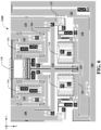
- FIG. 3 depicts further aspects of non-limiting embodiments of an exemplary gyroscope architecture 100, as described herein.
- the exemplary GY proof masses e.g. , GY proof masses 104, 106, 108, 110
- exemplary GX proof masses e.g. , GX proof masses 132, 134, 136, 138
- the coupling there between exemplary lever arms 112, 114, 116, 118, anchors 302, and various springs 145 ( e.g. , GZ spring 304, etc. ), couplings ( e.g. , GX or outer frame gyro to drive shuttle coupling 306, etc. ), suspension elements, etc. depicted therein.
- FIG. 3 depicts an exemplary stress isolation frame 308, according to further non-limiting aspects.
- offset shift can be induced by levitation force induced in the drive shuttles or induced by deformation of the gyroscope structure due to external stresses ( e.g. , package stresses). Offset shift can also be affected by other sources such as package stress, temperature effects, etc.
- an exemplary stress isolation frame 308 can be employed in various non-limiting embodiments. While not shown in FIG. 1 , an exemplary stress isolation frame 308 can be shown connected to all the outer anchor points 302 illustrated in FIG. 3 .
- exemplary stress isolation frame 308 can be connected to the package or the substrate 102, and the peripheral components of the components of exemplary gyroscope architecture 100 can be suspended therefrom and/or anchored to, including, but not limited to the four exemplary drive shuttles 310, exemplary coupling mechanisms or lever arms 128, 130, etc.
- package bend or deformation sensitivity can be improved, according to further non-limiting aspects, wherein offset resulting from bending of a package associated with the MEMS device can be reduced by employing one or more of an exemplary stress isolation frame 308, along with exemplary drive shuttles 310, etc. , as described herein.
- FIG. 3 further depicts exemplary drive sense combs 312, which can be configured to detect drive motion.
- exemplary drive sense combs 312 are depicted as coupled to GY or inner frame gyroscope components (e.g. , GY proof masses 104, 106, 108, 110), in non-limiting embodiments, in further non-limiting embodiments, exemplary drive sense combs 312 can be coupled to other of the various components of the exemplary gyroscope architecture 100, including, but not limited to, one or more of the four exemplary drive shuttles 310, etc.
- FIG. 1 is depicted as coupled to GY or inner frame gyroscope components (e.g. , GY proof masses 104, 106, 108, 110), in non-limiting embodiments, in further non-limiting embodiments, exemplary drive sense combs 312 can be coupled to other of the various components of the exemplary gyroscope architecture 100, including, but not limited to, one or more of the four exemplary drive shuttle
- FIG. 3 further depicts exemplary drive combs 314, which can be coupled to the exemplary drive shuttles 310 to generate the drive force at the drive frequency, and which can result in the drive motions of the respective various components of exemplary gyroscope architecture 100, as described above regarding FIGS. 1-2 .
- FIG. 3 depicts further capacitive electrodes 316 that can be configured to respectively detect motions of respective GZ proof masses (e.g. , GZ proof masses 120, 122, 124, 126), as further described above regarding FIGS. 1-2 .
- GZ proof masses e.g. , GZ proof masses 120, 122, 124, 126
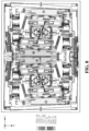
- FIG. 4 depicts still further exemplary aspects of non-limiting embodiments of an exemplary gyroscope architecture 100.
- FIG. 4 depicts relative locations of exemplary capacitive electrodes 156, 158, 160, 162, 164, 166, 168, 170, in the depiction of FIG. 3 , which can be configured to primarily facilitate detection of Coriolis forces acting on respective proof masses as a result of angular velocity associated with the MEMS device about respective axes ( e.g. , X or Y axes), for example, as further described above regarding FIG. 1 .
- respective axes e.g. , X or Y axes
- FIG. 5 depicts still further exemplary aspects of non-limiting embodiments of an exemplary gyroscope architecture 100.
- anchor 302 locations are depicted as black boxes, instead of as in FIGS. 1-2 .
- FIG. 5 depicts inset 502, which is further described, regarding FIG. 6 .
- FIG. 6 depicts still further exemplary aspects of non-limiting embodiments of an exemplary gyroscope architecture 100.
- FIG. 6 depicts the relative locations and configurations of various components of exemplary gyroscope architecture 100, as depicted in FIGS. 1-5 , for inset 502.
- FIG. 5 depicts still further exemplary aspects of non-limiting embodiments of an exemplary gyroscope architecture 100.
- anchor 302 locations are depicted as black boxes, instead of as in FIGS. 1-2 .
- FIG. 5 depicts inset 502, which is further described, regarding FIG. 6 .
- FIG. 6 depicts still further exemplary aspects of non-limiting embodiments of an exemplary g
- FIG. 7 depicts yet another non-limiting embodiment of an exemplary gyroscope architecture 100, depicting relative locations of exemplary capacitive electrodes 156, 158, 160, 162, 164, 166, 168, 170, in the depiction of FIG. 7 , which can be configured to primarily facilitate detection of Coriolis forces acting on respective proof masses as a result of angular velocity associated with the MEMS device about respective axes ( e.g. , X or Y axes), for example, as further described above regarding FIGS. 1 , 4 , etc.
- the coupling mechanisms or lever arms 128, 130 that are configured to couple the respective pairs of the four proof masses (e.g. , GZ proof masses 120, 122, 124, 126) motions, which corresponds respectively to construction of a functional fixed pivot point between respective pairs of GZ proof masses, as described above regarding FIGS. 1-2 .
- FIG. 8 depicts an exemplary drive mode shape of a non-limiting embodiment of an exemplary gyroscope architecture 100, according to further non-limiting aspects described herein.
- drive motion applied via the four exemplary drive shuttles 310 as described above result in deflection and translation of the various components of exemplary gyroscope architecture 100, as described herein.
- FIG. 8 It can be seen in FIG. 8 from the relative lack of displacement of the in-plane motion components (GZ), which are separated from the out-of-plane motion components (GX) and constrained by the coupling mechanisms or lever arms 128, 130 that are configured to couple the respective pairs of the four proof masses (e.g.
- GZ in-plane motion components
- GX out-of-plane motion components
- GZ proof masses 120, 122, 124, 126) motions various embodiments as described herein can be configured to constrain transmission of the out-of-plane motion components (GX, GY) to the in plain motion components (GZ) (drive shuttle, Z proof masses), and, thus, the transmission of the levitation force associated with the out-of-plane motion components (GX, GY) can be minimized.
- FIG. 9 depicts an exemplary GX mode shape of a non-limiting embodiment of an exemplary gyroscope architecture 100, according to still further non-limiting aspects described herein.
- FIG. 9 depicts the relative displacement above and below X-Y plane, where the "+" symbol indicates above plane X-Y plane displacement and the "-" symbol indicates below plane displacement, in lieu of color heat map or adequate grey scale resolution.
- the GX, outer frame, or saddle gyroscope sense mode is a balanced sense mode, where each of the GX proof masses are in anti-phase motion, as facilitated by exemplary fixed pivot point functionally generated by the structures indicated in FIG. 9 .
- FIG. 10 depicts an exemplary GY mode shape of a non-limiting embodiment of an exemplary gyroscope architecture, according to still further non-limiting aspects described herein.
- FIG. 10 depicts the relative displacement above and below X-Y plane, where the "+" symbol indicates above plane X-Y plane displacement and the "-" symbol indicates below plane displacement, in lieu of color heat map or adequate grey scale resolution.
- GY or frame gyroscope sense mode is a balanced sense mode, where each of the GY proof masses are in anti-phase motion ( e.g. , both linear and angular momentum balanced). It can be further seen in FIG.
- various embodiments as described herein can be configured to constrain transmission of the out-of-plane motion components (GX, GY) to the in plain motion components (GZ) (drive shuttle, Z proof masses), and, thus, the transmission of the levitation force associated with the out-of-plane motion components (GX, GY) can be minimized.
- FIG. 10 can facilitate isolation of levitation forces on the drive combs ( e.g. , drive combs 314) from being transferred to the frame proof masses.
- FIG. 11 depicts an exemplary GZ sense mode shape of a non-limiting embodiment of an exemplary gyroscope architecture, according to non-limiting aspects described herein.
- FIG. 11 depicts the relative displacement in the X-Y plane, where the "+" symbol indicates +X displacement and the "-" symbol indicates -X displacement, in lieu of color heat map or adequate grey scale resolution. It can be seen in FIG. 11 , that the GZ gyroscope sense mode is a balanced sense mode, where each of the GZ proof masses are in anti-phase motion.
- FIG. 12 depicts an exemplary GZ parasitic mode shape of a non-limiting embodiment of an exemplary gyroscope architecture, according to still further non-limiting aspects described herein.
- FIG. 12 depicts the relative displacement in the X-Y plane, where the "+" symbol indicates + displacement and the "-" symbol indicates - displacement, in lieu of color heat map or adequate grey scale resolution. It can be seen in FIG. 12 , that the GZ gyroscope has a linear and angular momentum balanced parasitic mode.
- exemplary non-limiting embodiments can comprise a 3-axis Coriolis vibratory rate gyroscope, in a roughly 2 dimensional device architecture, with the geometry largely being flat, and capable of being fabricated in silicon.
- exemplary embodiments as described herein can comprise two inner frame (e.g., GY) gyroscopes, wherein the inner frame gyroscopes facilitate GY sense mode and drive system coupling, two outer frame, or saddle gyroscope, four drive shuttles coupled to the two outer frame gyroscopes, four GZ proof masses coupled to the GY or inner frame gyroscopes, and/or two lever arms or coupling mechanisms that facilitate coupling GZ proof masses.
- GY inner frame
- various exemplary embodiments can be configured such that components can be removed from an exemplary overall architecture to fabricate a single axis or two axis gyroscope and/or can be configured such that a number of proof-masses can be reduced in half from an exemplary overall architecture to fabricate a half-gyroscope, as further described herein.
- FIG. 13 illustrates a functional block diagram of other non-limiting embodiments of an exemplary gyroscope architecture 100, according to further non-limiting aspects of the subject disclosure.
- an exemplary 3-axis (e.g. , GX, GY, and GZ) gyroscope architecture 100 can be reduced to a 2-axis or 1-axis gyroscope by removing components from the architecture, employing fewer sense transducers, etc.
- exemplary gyroscope architectures as described herein can be functionally cut in half to create a more compact 3-axis (e.g.
- GX, GY, and GZ gyroscope
- the four GZ proof masses can be omitted to fabricate a balanced two axis ( e.g. , X-Y gyroscope).
- two GX proof masses, or outer frame gyroscopes and respective GY or inner frame gyroscope can be omitted from the fabrication as in FIG.
- GY electrodes 162, 164, 166, 168 can be omitted from the fabrication or electrical connection, such that variants of exemplary gyroscope architecture 100 could yield a 1-axis gyroscope.
- FIG. 14 illustrates another functional block diagram of still other non-limiting embodiments of an exemplary gyroscope architecture 100, according to further non-limiting aspects of the subject disclosure.
- exemplary gyroscope architecture 100 could yield a more compact but non-balanced drive and sense 3-axis gyroscope by omitting one half of the components of exemplary gyroscope architecture 100.
- Other variants can include omission of the GZ proof masses to yield a 2-axis, X-Y gyroscope with drive system coupled to the GY or frame gyros as described herein.
- an exemplary MEMS device (e.g. , comprising exemplary gyroscope architecture 100, or portions thereof) comprises one or more inner frame gyroscope (e.g. , GY or inner frame gyroscope comprising two or more GY proof masses 104, 106, 108, 110, etc. ) configured to sense a first component of angular velocity associated with the MEMS device ( e.g. , comprising exemplary gyroscope architecture 100, or portions thereof) around a first axis (e.g. , Y axis), for example, as described herein.
- a first axis e.g. , Y axis
- a frame gyroscope can be understood to comprise a guided mass system comprising two proof masses and a rotating arm connecting the two proof masses and constraining the proof masses to anti-phase motion.
- an outer frame gyroscope can be understood to surround and/or be flexibly coupled to the inner frame gyroscope.
- an exemplary MEMS device e.g. , comprising exemplary gyroscope architecture 100, or portions thereof
- an outer frame gyroscope comprising at least two proof masses (e.g. , GX or outer frame gyroscope comprising two or more GX proof masses 132, 134, 136, 138, etc ), flexibly coupled ( e.g. , via coupling 148/150/152/154, or portions thereof) to the one or more inner frame gyroscope (e.g. , GY or inner frame gyroscope comprising two or more GY proof masses 104, 106, 108, 110, etc.
- an inner frame gyroscope comprising at least two proof masses (e.g. , GX or outer frame gyroscope comprising two or more GX proof masses 132, 134, 136, 138, etc ), flexibly coupled ( e.g. , via coupling 148/150/152/154, or portions
- a second component of angular velocity associated with the MEMS device e.g. , comprising exemplary gyroscope architecture 100, or portions thereof
- a second axis e.g. , X axis
- first axis e.g. , Y axis
- an exemplary MEMS device (e.g. , comprising exemplary gyroscope architecture 100, or portions thereof) further comprises two or more additional proof masses (e.g. , of GZ proof masses 120, 122, 124, 126) coupled to the one or more inner frame gyroscope ( e.g. , GY or inner frame gyroscope comprising two or more GY proof masses 104, 106, 108, 110, etc. ) and configured to sense a third component of angular velocity associated with the MEMS device ( e.g. , comprising exemplary gyroscope architecture 100, or portions thereof) around a third axis ( e.g. , Z axis) that can be orthogonal to the first axis ( e.g. , Y axis) and the second axis ( e.g. , X axis).
- a third axis e.g. , Z axis
- a motion associated with the two or more proof masses can be coupled, at least in part, to in plane motion (e.g. , X-Y plane) of the one or more inner frame gyroscope (e.g. , GY or inner frame gyroscope comprising two or more GY proof masses 104, 106, 108, 110, etc. ) via respective coupling mechanisms (e.g. , via coupling mechanisms or lever arms 128, 130), and wherein the in plane motion can be defined with reference to a plane comprising the first axis ( e.g.
- the two or more proof masses can be configured to facilitate constraining, at least in part, the motion associated with the two or more proof masses (e.g. , of GZ proof masses 120, 122, 124, 126) into a condition of linear and angular momentum balance.
- an exemplary MEMS device (e.g. , comprising exemplary gyroscope architecture 100, or portions thereof) can further comprise one or more coupling mechanism (e.g. , coupling mechanisms or lever arms 128, 130) between the two or more proof masses ( e.g. , of GZ proof masses 120, 122, 124, 126) configured to force the two or more proof masses ( e.g. , of GZ proof masses 120, 122, 124, 126) into anti-phase motion as a result of the third component of angular velocity applied to the MEMS device ( e.g. , comprising exemplary gyroscope architecture 100, or portions thereof) around the third axis ( e.g. , Z axis).
- coupling mechanism e.g. , coupling mechanisms or lever arms 128, 130
- an exemplary MEMS device e.g. , comprising exemplary gyroscope architecture 100, or portions thereof
- an exemplary MEMS device further comprises two or more drive shuttles (e.g. , drive shuttles 310) flexibly coupled ( e.g. , via lever arms 112, 114, 116, 118, or portions thereof) to the inner frame gyroscope (e.g. , GY or inner frame gyroscope comprising two or more GY proof masses 104, 106, 108, 110, etc .) and to the at least two proof masses of the outer frame gyroscope (e.g.
- one or more of the outer frame gyroscope e.g. , GX or outer frame gyroscope comprising two or more GX proof masses 132, 134, 136, 138, etc.
- the one or more inner frame gyroscope e.g. , GY or inner frame gyroscope comprising two or more GY proof masses 104, 106, 108, 110, etc.
- one or more of the two or more drive shuttles can be configured to sense drive motion ( e.g. , via drive sense combs 312) associated with the oscillation.
- the two or more drive shuttles e.g.
- drive shuttles 310) can be configured to move in anti-phase drive motion and can be configured to minimize transmission of out of plane motion of the two or more drive shuttles ( e.g. , drive shuttles 310) to the one or more inner frame gyroscope ( e.g. , GY or inner frame gyroscope comprising two or more GY proof masses 104, 106, 108, 110, etc. ).
- inner frame gyroscope e.g. , GY or inner frame gyroscope comprising two or more GY proof masses 104, 106, 108, 110, etc.
- an exemplary MEMS device e.g. , comprising exemplary gyroscope architecture 100, or portions thereof
- a set of drive electrodes e.g. , drive combs 3114
- an exemplary MEMS device e.g. , comprising exemplary gyroscope architecture 100, or portions thereof
- one or more inner frame gyroscope e.g. , GY or inner frame gyroscope comprising two or more GY proof masses 104, 106, 108, 110, etc.
- a first component of angular velocity associated with the MEMS device e.g. , comprising exemplary gyroscope architecture 100, or portions thereof
- a first axis e.g. , Y axis
- an exemplary MEMS device (e.g. , comprising exemplary gyroscope architecture 100, or portions thereof) can further comprise two or more proof masses (e.g. , of GZ proof masses 120, 122, 124, 126) coupled to the one or more inner frame gyroscope ( e.g. , GY or inner frame gyroscope comprising two or more GY proof masses 104, 106, 108, 110, etc. ) and configured to sense a second component of angular velocity associated with the MEMS device (e.g. , comprising exemplary gyroscope architecture 100, or portions thereof) around a second axis (e.g. , Z axis) that can be orthogonal to the first axis ( e.g. , Y axis).
- two or more proof masses e.g. , of GZ proof masses 120, 122, 124, 1266
- inner frame gyroscope e.g. , GY or
- an exemplary MEMS device comprising exemplary gyroscope architecture 100, or portions thereof
- exemplary MEMS device comprising one or more coupling mechanism between the two or more proof masses (e.g. , of GZ proof masses 120, 122, 124, 126) configured to force the two or more proof masses ( e.g. , of GZ proof masses 120, 122, 124, 126) into anti-phase motion as a result of the second component of angular velocity applied to the MEMS device (e.g. , comprising exemplary gyroscope architecture 100, or portions thereof) around the second axis ( e.g. , Z axis), for example, as described herein.
- the MEMS device e.g. , comprising exemplary gyroscope architecture 100, or portions thereof
- second axis e.g. , Z axis
- a motion associated with the two or more proof masses can be coupled, at least in part, to in plane motion of the one or more inner frame gyroscope (e.g. , GY or inner frame gyroscope comprising two or more GY proof masses 104, 106, 108, 110, etc. ) via respective coupling mechanisms, and wherein the in plane motion can be defined with reference to a plane normal to the second axis ( e.g. , X-Y plane).
- the two or more proof masses e.g.
- GZ proof masses 120, 122, 124, 126) can be configured to facilitate constraining, at least in part, the motion associated with the two or more proof masses ( e.g. , of GZ proof masses 120, 122, 124, 126) into a condition of linear and angular momentum balance.
- an exemplary MEMS device (e.g. , comprising exemplary gyroscope architecture 100, or portions thereof) can further comprise two or more drive shuttles (e.g. , drive shuttles 310) coupled to the one or more inner frame gyroscope ( e.g. , GY or inner frame gyroscope comprising two or more GY proof masses 104, 106, 108, 110, etc. ) and configured to force the one or more inner frame gyroscope ( e.g. , GY or inner frame gyroscope comprising two or more GY proof masses 104, 106, 108, 110, etc. ) into oscillation.
- two or more drive shuttles e.g. , drive shuttles 310 coupled to the one or more inner frame gyroscope ( e.g. , GY or inner frame gyroscope comprising two or more GY proof masses 104, 106, 108, 110, etc. ) and configured to force the one
- the two or more drive shuttles can be configured to move in anti-phase drive motion and can be configured to minimize transmission of out of plane motion of the two or more drive shuttles ( e.g. , drive shuttles 310) to the one or more inner frame gyroscope ( e.g. , GY or inner frame gyroscope comprising two or more GY proof masses 104, 106, 108, 110, etc. ).
- the inner frame gyroscope e.g. , GY or inner frame gyroscope comprising two or more GY proof masses 104, 106, 108, 110, etc.
- an exemplary MEMS device (e.g. , comprising exemplary gyroscope architecture 100, or portions thereof) comprising two inner frame gyroscopes ( e.g. , GY or inner frame gyroscope comprising GY proof masses 104, 106, 108, 110, etc. ) configured to sense a first component of angular velocity associated with the MEMS device ( e.g. , comprising exemplary gyroscope architecture 100, or portions thereof) around a first axis ( e.g. , Y axis), for example, as described herein.
- an exemplary MEMS device e.g.
- one of the two inner frame gyroscopes e.g. , GY or inner frame gyroscope comprising GY proof masses 104, 106, 108, 110, etc.
- one of the two inner frame gyroscopes can be flexibly coupled ( e.g. , via a spring or flexure 145) to the other of the two inner frame gyroscopes ( e.g.
- GY or inner frame gyroscope comprising GY proof masses 104, 106, 108, 110, etc.
- the two inner frame gyroscopes e.g. , GY or inner frame gyroscope comprising GY proof masses 104, 106, 108, 110, etc.
- an exemplary MEMS device (e.g. , comprising exemplary gyroscope architecture 100, or portions thereof) can further comprise two outer frame gyroscopes (e.g. , GX or outer frame gyroscope comprising GX proof masses 132, 134, 136, 138, etc. ) configured to sense a second component of angular velocity associated with the MEMS device ( e.g. , comprising exemplary gyroscope architecture 100, or portions thereof) around a second axis (e.g. , X axis) that can be orthogonal to the first axis ( e.g. , Y axis).
- two outer frame gyroscopes e.g. , GX or outer frame gyroscope comprising GX proof masses 132, 134, 136, 138, etc.
- a second component of angular velocity associated with the MEMS device e.g. , comprising exemplary gyr
- the two outer frame gyroscopes (e.g. , GX or outer frame gyroscope comprising GX proof masses 132, 134, 136, 138, etc. ) can be coupled ( e.g. , via coupling 148/150/152/154, or portions thereof) to the two inner frame gyroscope ( e.g. , GY or inner frame gyroscope comprising two or more GY proof masses 104, 106, 108, 110, etc. ) at least in part via the four drive shuttles ( e.g. , drive shuttles 310).
- the outer frame gyroscope e.g., GX or outer frame gyroscope comprising GX proof masses 132, 134, 136, 138, etc.
- the two inner frame gyroscope e.g. , GY or inner frame gyroscope comprising two or more GY proof masses 104, 106, 108, 110, etc
- GX or outer frame gyroscope comprising two or more GX proof masses 132, 134, 136, 138, etc.
- the one or more of the two inner frame gyroscopes can be configured to be driven by a set of drive electrodes ( e.g. , drive combs 314, as further described herein.
- the two outer frame gyroscopes e.g. , GX or outer frame gyroscope comprising GX proof masses 132, 134, 136, 138, etc.
- the two inner frame gyroscopes e.g. , GY or inner frame gyroscope comprising GY proof masses 104, 106, 108, 110, etc.
- the two outer frame gyroscopes e.g. , GX or outer frame gyroscope comprising GX proof masses 132, 134, 136, 138, etc.
- the two inner frame gyroscopes e.g. , GY or inner frame gyroscope comprising GY proof masses 104, 106, 108, 110, etc.
- GX or outer frame gyroscope comprising GX proof masses 132, 134, 136, 138, etc.
- the two inner frame gyroscopes e.g. , GY or inner frame gyroscope comprising GY proof masses 104, 106, 108, 110, etc.
- an exemplary MEMS device (e.g. , comprising exemplary gyroscope architecture 100, or portions thereof) can further comprise four proof masses (e.g. , of GZ proof masses 120, 122, 124, 126) coupled to the two inner frame gyroscopes ( e.g. , GY or inner frame gyroscope comprising GY proof masses 104, 106, 108, 110, etc. ) and configured to sense a third component of angular velocity associated with the MEMS device ( e.g. , comprising exemplary gyroscope architecture 100, or portions thereof) around a third axis ( e.g. , Z axis) that can be orthogonal to the first axis ( e.g. , Y axis) and the second axis ( e.g. , X axis).
- proof masses e.g. , of GZ proof masses 120, 122, 124, 1266
- an exemplary MEMS device (e.g. , comprising exemplary gyroscope architecture 100, or portions thereof) comprising two coupling mechanisms (e.g. , coupling mechanisms or lever arms 128, 130) associated with pairs of the four proof masses ( e.g. , of GZ proof masses 120, 122, 124, 126) configured to force the pairs of the four proof masses ( e.g. , of GZ proof masses 120, 122, 124, 126) into anti-phase motion as a result of the third component of angular velocity applied to the MEMS device ( e.g. , comprising exemplary gyroscope architecture 100, or portions thereof) around the third axis ( e.g.
- an exemplary MEMS device (e.g. , comprising exemplary gyroscope architecture 100, or portions thereof) can further comprise four drive shuttles (e.g. , drive shuttles 310) coupled to one or more of the two inner frame gyroscopes (e.g. , GY or inner frame gyroscope comprising GY proof masses 104, 106, 108, 110, etc. ) and the outer frame gyroscope (e.g. , GX or outer frame gyroscope comprising two or more GX proof masses 132, 134, 136, 138, etc.
- the two inner frame gyroscopes e.g. , GY or inner frame gyroscope comprising GY proof masses 104, 106, 108, 110, etc.
- the outer frame gyroscope e.g. , GX or outer frame gyroscope comprising two or more GX proof masses 132, 134, 136,
- the two inner frame gyroscopes e.g. , GY or inner frame gyroscope comprising GY proof masses 104, 106, 108, 110, etc.
- the outer frame gyroscope e.g. , GX or outer frame gyroscope comprising two or more GX proof masses 132, 134, 136, 138, etc.
- the outer frame gyroscope e.g. , GX or outer frame gyroscope comprising two or more GX proof masses 132, 134, 136, 138, etc.
- the two inner frame gyroscopes e.g. , GY or inner frame gyroscope comprising GY proof masses 104, 106, 108, 110, etc.
- one or more of the four drive shuttles can be configured to sense drive motion (e.g. , via drive sense combs 312) associated with the oscillation.
- pairs of the four drive shuttles e.g. , drive shuttles 310) can be configured to move in anti-phase drive motion and can be configured to minimize transmission of out of plane motion of the pairs of the four drive shuttles ( e.g.
- an exemplary MEMS device (e.g. , comprising exemplary gyroscope architecture 100, or portions thereof) comprises two outer frame lever arms ( e.g. , via fixed pivot points 144 and respective outer frame lever arms 140/142 or portions thereof ) associated with two outer frame gyroscopes ( e.g. , GX or outer frame gyroscope comprising GX proof masses 132, 134, 136, 138, etc. ) configured to force the two outer frame gyroscopes ( e.g. , GX or outer frame gyroscope comprising GX proof masses 132, 134, 136, 138, etc.
- the MEMS device e.g. , comprising exemplary gyroscope architecture 100, or portions thereof
- the second axis e.g. , X axis
- exemplary MEMS device e.g. , comprising exemplary gyroscope architecture 100, or portions thereof
- a stress isolation frame e.g. , stress isolation frame 308 coupled to the MEMS device ( e.g. , comprising exemplary gyroscope architecture 100, or portions thereof) and configured to reject stress transmitted from a package associated with the MEMS device ( e.g. , comprising exemplary gyroscope architecture 100, or portions thereof) to the MEMS device ( e.g. , comprising exemplary gyroscope architecture 100, or portions thereof), for example, as further described herein.
- a stress isolation frame e.g. , stress isolation frame 308
Landscapes
- Physics & Mathematics (AREA)
- Engineering & Computer Science (AREA)
- General Physics & Mathematics (AREA)
- Radar, Positioning & Navigation (AREA)
- Remote Sensing (AREA)
- Gyroscopes (AREA)
Claims (11)
- Ein mikroelektromechanisches System, MEMS-Vorrichtung, aufweisend:mindestens ein Innenrahmen-Gyroskop, das so konfiguriert ist, dass es eine erste Komponente von Winkelgeschwindigkeit erfasst, die mit der MEMS-Vorrichtung um eine erste Achse assoziiert ist;ein Außenrahmen-Gyroskop, das mindestens zwei Prüfmassen aufweist, die flexibel mit dem mindestens einen Innenrahmen-Gyroskop gekoppelt sind und so konfiguriert sind, dass sie eine zweite Komponente von Winkelgeschwindigkeit erfassen, die mit der MEMS-Vorrichtung um eine zweite Achse assoziiert ist, die orthogonal zur ersten Achse ist;mindestens zwei zusätzliche Prüfmassen, die mit dem mindestens einen Innenrahmen-Gyroskop gekoppelt sind, wobei die mindestens zwei zusätzlichen Prüfmassen so konfiguriert sind, dass sie eine dritte Komponente von Winkelgeschwindigkeit erfassen, die mit der MEMS-Vorrichtung um eine dritte Achse assoziiert ist, die orthogonal zur ersten Achse und zur zweiten Achse ist;zwei äußere Rahmenhebel, die mit dem Außenrahmen-Gyroskop assoziiert sind, mit den mindestens zwei Prüfmassen des Außenrahmen-Gyroskops gekoppelt sind und so konfiguriert sind, dass sie das Außenrahmen-Gyroskop in eine gegenphasige Bewegung zwingen; undmindestens zwei Antriebs-Shuttles, die flexibel mit den mindestens zwei Prüfmassen des Außenrahmen-Gyroskops und mit dem mindestens einen Innenrahmen-Gyroskop gekoppelt sind und so konfiguriert sind, dass sie das mindestens eine Innenrahmen-Gyroskop und das Außenrahmen-Gyroskop in eine gegenphasige Bewegung zwingen.
- Die MEMS-Vorrichtung nach Anspruch 1, wobei:eine mit den mindestens zwei Prüfmassen verbundene Bewegung zumindest teilweise mit einer Bewegung in der Ebene des mindestens einen Innenrahmen-Gyroskops über jeweilige Kopplungsmechanismen gekoppelt ist, wobei die Bewegung in der Ebene in Bezug auf eine Ebene definiert ist, die die erste Achse und die zweite Achse umfasst, und wobei die mit den mindestens zwei Prüfmassen verbundene Bewegung linear ist und der Drehimpuls durch Kopplung der mindestens zwei Prüfmassen mit dem mindestens einen Innenrahmen-Gyroskop durch die mindestens zwei Antriebs-Shuttles ausgeglichen wird; odermindestens ein Kopplungsmechanismus zwischen den mindestens zwei Prüfmassen, der so konfiguriert ist, dass er die mindestens zwei Prüfmassen in eine gegenphasige Bewegung zwingt, als Ergebnis der dritten Komponente der Winkelgeschwindigkeit, die auf die MEMS-Vorrichtung um die dritte Achse herum angewendet wird.
- Die MEMS-Vorrichtung nach Anspruch 1 bis 2, wobei:
mindestens eines, das Außenrahmen-Gyroskop, das mindestens eine Innenrahmen-Gyroskop, oder mindestens einer der mindestens zwei Antriebs-Shuttles so konfiguriert ist, dass er eine mit der gegenphasigen Bewegung verbundene Antriebsbewegung erfasst. - Die MEMS-Vorrichtung nach einem der Ansprüche 1 bis 3, wobei mindestens eines, das Außenrahmen-Gyroskop oder das mindestens eine Innenrahmen-Gyroskop so konfiguriert ist, dass er durch einen Satz von Antriebselektroden angetrieben wird.
- Ein mikroelektromechanisches System, MEMS-Vorrichtung gemäß Anspruch 1, aufweisend:zwei Innenrahmen-Gyroskope, die so konfiguriert sind, dass sie eine erste Komponente von Winkelgeschwindigkeit erfassen, die mit der MEMS-Vorrichtung um eine erste Achse assoziiert ist;zwei Außenrahmen-Gyroskope, die so konfiguriert sind, dass sie eine zweite Komponente von Winkelgeschwindigkeit erfassen, die mit der MEMS-Vorrichtung um eine zweite Achse assoziiert ist, die orthogonal zur ersten Achse ist,wobei jedes der beiden Außenrahmen-Gyroskope zwei Prüfmassen umfasst, die mit einem der beiden Innenrahmen-Gyroskope gekoppelt sind und so konfiguriert sind, dass sie eine dritte Komponente von Winkelgeschwindigkeit erfassen, die mit der MEMS-Vorrichtung um eine dritte Achse assoziiert ist, die orthogonal zur ersten Achse und zur zweiten Achse ist;wobei die MEMS-Vorrichtung vier Antriebs-Shuttles umfasst, die flexibel zwischen den beiden Innenrahmen-Gyroskopen und den Prüfmassen der beiden Außenrahmen-Gyroskope gekoppelt sind und so konfiguriert sind, dass sie die beiden Innenrahmen-Gyroskope und die beiden Außenrahmen-Gyroskope in eine gegenphasige Bewegung zwingen;zwei äußere Rahmenhebel, wobei jeder äußere Rahmenhebel mit einem der beiden Außenrahmen-Gyroskopen assoziiert ist und mit den beiden Prüfmassen des zugehörigen Außenrahmen-Gyroskops gekoppelt ist, wobei die beiden äußeren Rahmenhebel so konfiguriert sind, dass sie die beiden Außenrahmen-Gyroskope in eine gegenphasige Bewegung zwingen.
- Die MEMS-Vorrichtung nach Anspruch 5, ferner aufweisend:
zwei Kopplungsmechanismen, die mit Paaren der vier Prüfmassen verbunden sind, die so konfiguriert sind, dass sie die Paare der vier Prüfmassen in eine gegenphasige Bewegung zwingen, und zwar als Ergebnis der dritten Komponente der Winkelgeschwindigkeit, die auf die MEMS-Vorrichtung um die dritte Achse herum angewendet wird, und so konfiguriert sind, dass sie in den vier Prüfmassen als Ergebnis der beiden Innenrahmen-Gyroskope zu keinem Netto-Drehimpuls führen. - Die MEMS-Vorrichtung nach Anspruch 5 oder 6, wobei die MEMS-Vorrichtung so konfiguriert ist, dass sie als mindestens ein Einachsen-Gyroskop, ein Zweiachsen-Gyroskop oder als Dreiachsen-Gyroskop arbeitet.
- Die MEMS-Vorrichtung nach Anspruch 5, wobei
mindestens eines der beiden Außenrahmen-Gyroskope, mindestens eines der beiden Innenrahmen-Gyroskope oder mindestens einer der vier Antriebs-Shuttles so konfiguriert ist, dass er eine mit der gegenphasigen Bewegung verbundene Antriebsbewegung erfasst, und wobei das mindestens eine der beiden Außenrahmen-Gyroskope oder deas mindestens eine der beiden Innenrahmen-Gyroskope so konfiguriert ist, dass es durch einen Satz von Antriebselektroden angetrieben wird. - Die MEMS-Vorrichtung nach Anspruch 5, wobei die Bewegung der beiden Außenrahmen-Gyroskope und der beiden Innenrahmen-Gyroskope außerhalb der Ebene und innerhalb der Ebene über eine jeweilige Kopplung der vier Prüfmassen an die beiden Innenrahmen-Gyroskope durch die vier Antriebs-Shuttles in Phase gehalten werden und wobei eines der beiden Innenrahmen-Gyroskope flexibel an das andere der beiden Innenrahmen-Gyroskope gekoppelt ist und die Bewegung außerhalb der Ebene und innerhalb der Ebene der beiden Innenrahmen-Gyroskope über die Kopplung des einen der beiden Innenrahmen-Gyroskope an das andere der beiden Innenrahmen-Gyroskope in Phase gehalten werden.
- Die MEMS-Vorrichtung nach Anspruch 5, ferner aufweisend:
Kopplungsmechanismen, die mit zwei Außenrahmen-Gyroskopen verbunden sind, die so konfiguriert sind, dass sie die beiden Außenrahmen-Gyroskope in eine gegenphasige Bewegung zwingen, und zwar als Ergebnis der zweiten Komponente der Winkelgeschwindigkeit, die auf die MEMS-Vorrichtung um die zweite Achse herum angewendet wird. - Die MEMS-Vorrichtung nach einem der Ansprüche 5 bis 10, die ferner aufweisend:
einen Spannungsisolationsrahmen, der die MEMS-Vorrichtung mit mindestens einem Substrat oder Gehäuse koppelt, das die MEMS-Vorrichtung umfasst.
Applications Claiming Priority (3)
| Application Number | Priority Date | Filing Date | Title |
|---|---|---|---|
| US16/138,637 US11118907B2 (en) | 2018-09-21 | 2018-09-21 | Drive and sense balanced, fully-coupled 3-axis gyroscope |
| PCT/US2019/052243 WO2020061506A1 (en) | 2018-09-21 | 2019-09-20 | Drive and sense balanced, fully-coupled 3-axis gyroscope |
| EP19782854.4A EP3853557B1 (de) | 2018-09-21 | 2019-09-20 | Drive-und-sense-ausgeglichenes, vollständig gekoppeltes dreiachsiges gyroskop |
Related Parent Applications (2)
| Application Number | Title | Priority Date | Filing Date |
|---|---|---|---|
| EP19782854.4A Division EP3853557B1 (de) | 2018-09-21 | 2019-09-20 | Drive-und-sense-ausgeglichenes, vollständig gekoppeltes dreiachsiges gyroskop |
| EP19782854.4A Division-Into EP3853557B1 (de) | 2018-09-21 | 2019-09-20 | Drive-und-sense-ausgeglichenes, vollständig gekoppeltes dreiachsiges gyroskop |
Publications (2)
| Publication Number | Publication Date |
|---|---|
| EP4134622A1 EP4134622A1 (de) | 2023-02-15 |
| EP4134622B1 true EP4134622B1 (de) | 2025-04-02 |
Family
ID=68136566
Family Applications (2)
| Application Number | Title | Priority Date | Filing Date |
|---|---|---|---|
| EP19782854.4A Active EP3853557B1 (de) | 2018-09-21 | 2019-09-20 | Drive-und-sense-ausgeglichenes, vollständig gekoppeltes dreiachsiges gyroskop |
| EP22196652.6A Active EP4134622B1 (de) | 2018-09-21 | 2019-09-20 | Antriebs- und erfassungsausgeglichenes, vollständig gekoppeltes dreiachsiges gyroskop |
Family Applications Before (1)
| Application Number | Title | Priority Date | Filing Date |
|---|---|---|---|
| EP19782854.4A Active EP3853557B1 (de) | 2018-09-21 | 2019-09-20 | Drive-und-sense-ausgeglichenes, vollständig gekoppeltes dreiachsiges gyroskop |
Country Status (4)
| Country | Link |
|---|---|
| US (2) | US11118907B2 (de) |
| EP (2) | EP3853557B1 (de) |
| CN (1) | CN112739982B (de) |
| WO (1) | WO2020061506A1 (de) |
Families Citing this family (20)
| Publication number | Priority date | Publication date | Assignee | Title |
|---|---|---|---|---|
| US10696541B2 (en) | 2016-05-26 | 2020-06-30 | Honeywell International Inc. | Systems and methods for bias suppression in a non-degenerate MEMS sensor |
| US11692826B2 (en) * | 2019-03-29 | 2023-07-04 | Panasonic Intellectual Property Management Co., Ltd. | Angular velocity sensor |
| CN112556675B (zh) * | 2019-09-10 | 2023-03-07 | 昇佳电子股份有限公司 | 微机电陀螺仪 |
| US11193771B1 (en) * | 2020-06-05 | 2021-12-07 | Analog Devices, Inc. | 3-axis gyroscope with rotational vibration rejection |
| US11680798B2 (en) | 2020-08-24 | 2023-06-20 | Invensense, Inc. | Digital demodulator and complex compensator for MEMS gyroscope |
| CN112113554B (zh) * | 2020-09-02 | 2024-10-29 | 美新半导体(天津)有限公司 | 一种解耦式微陀螺 |
| US11525680B2 (en) * | 2021-02-17 | 2022-12-13 | Nxp Usa, Inc. | Angular rate sensor with centrally positioned coupling structures |
| GB202107476D0 (en) | 2021-05-26 | 2021-07-07 | Autorient Tech As | Angular rate sensors |
| CN113310478B (zh) * | 2021-06-23 | 2025-09-02 | 美新半导体(天津)有限公司 | 一种离面检测陀螺仪 |
| DE102021212100A1 (de) * | 2021-10-27 | 2023-04-27 | Robert Bosch Gesellschaft mit beschränkter Haftung | Mikromechanisches Bauteil für einen Drehratensensor |
| CN116660570A (zh) * | 2022-02-18 | 2023-08-29 | 华为技术有限公司 | 角速度传感器、惯性传感器和电子设备 |
| CN217155417U (zh) * | 2022-02-22 | 2022-08-09 | 瑞声开泰科技(武汉)有限公司 | 一种三轴检测的mems陀螺 |
| CN114719834B (zh) * | 2022-03-09 | 2025-04-22 | 瑞声开泰科技(武汉)有限公司 | 一种三轴mems陀螺 |
| CN114858152B (zh) * | 2022-03-30 | 2025-06-17 | 瑞声开泰科技(武汉)有限公司 | 一种mems单轴陀螺 |
| CN114646309B (zh) * | 2022-05-18 | 2022-08-23 | 绍兴圆方半导体有限公司 | 三轴陀螺仪 |
| CN115389781B (zh) * | 2022-07-29 | 2025-12-19 | 瑞声开泰科技(武汉)有限公司 | 一种加速度计 |
| CN115493577B (zh) * | 2022-08-16 | 2025-01-17 | 瑞声开泰科技(武汉)有限公司 | 一种三轴陀螺仪 |
| US12222203B2 (en) * | 2022-09-20 | 2025-02-11 | AAC Kaitai Technologies (Wuhan) CO., LTD | Fully decoupled three-axis MEMS gyroscope |
| GB2626998B (en) * | 2023-02-13 | 2025-06-11 | Lapadatu Daniel | Mechanically amplified high-precision, high-stability angular rate sensors |
| US20250290751A1 (en) * | 2024-03-12 | 2025-09-18 | Invensense, Inc. | Compact drive and sense balanced multi-axis gyroscope |
Family Cites Families (10)
| Publication number | Priority date | Publication date | Assignee | Title |
|---|---|---|---|---|
| US8549915B2 (en) * | 2009-10-23 | 2013-10-08 | The Regents Of The University Of California | Micromachined gyroscopes with 2-DOF sense modes allowing interchangeable robust and precision operation |
| ITTO20091042A1 (it) * | 2009-12-24 | 2011-06-25 | St Microelectronics Srl | Giroscopio integrato microelettromeccanico con migliorata struttura di azionamento |
| US8616057B1 (en) * | 2010-01-23 | 2013-12-31 | Minyao Mao | Angular rate sensor with suppressed linear acceleration response |
| US10914584B2 (en) * | 2011-09-16 | 2021-02-09 | Invensense, Inc. | Drive and sense balanced, semi-coupled 3-axis gyroscope |
| CN102607545A (zh) * | 2012-04-12 | 2012-07-25 | 厦门大学 | 基于碳纳米管阵列场发射的微机械陀螺仪 |
| EP3184961B1 (de) | 2013-09-30 | 2021-01-06 | Invensense, Inc. | Mikrogefertigtes gyroskop mit einem geführten massesystem |
| EP2887013B1 (de) * | 2013-12-18 | 2016-08-10 | Tronic's Microsystems | MEMS-Sensor zur Messung der Z-Achsen-Winkelgeschwindigkeit |
| CN104406579B (zh) * | 2014-11-27 | 2017-05-10 | 歌尔股份有限公司 | 微机电可变形结构和三轴多自由度微机电陀螺仪 |
| CN104613952B (zh) * | 2015-02-12 | 2017-09-19 | 东南大学 | 三轴单片集成全解耦角振动环式硅陀螺仪及其加工方法 |
| CN107063223B (zh) * | 2017-04-17 | 2019-04-30 | 东南大学 | 单片式谐振加速度计陀螺仪结构 |
-
2018
- 2018-09-21 US US16/138,637 patent/US11118907B2/en active Active
-
2019
- 2019-09-20 WO PCT/US2019/052243 patent/WO2020061506A1/en not_active Ceased
- 2019-09-20 EP EP19782854.4A patent/EP3853557B1/de active Active
- 2019-09-20 EP EP22196652.6A patent/EP4134622B1/de active Active
- 2019-09-20 CN CN201980061301.6A patent/CN112739982B/zh active Active
-
2021
- 2021-09-03 US US17/467,145 patent/US11841228B2/en active Active
Also Published As
| Publication number | Publication date |
|---|---|
| WO2020061506A1 (en) | 2020-03-26 |
| EP3853557A1 (de) | 2021-07-28 |
| CN112739982A (zh) | 2021-04-30 |
| EP4134622A1 (de) | 2023-02-15 |
| US20200096337A1 (en) | 2020-03-26 |
| CN112739982B (zh) | 2025-04-25 |
| US20210396519A1 (en) | 2021-12-23 |
| EP3853557B1 (de) | 2024-04-17 |
| US11118907B2 (en) | 2021-09-14 |
| US11841228B2 (en) | 2023-12-12 |
Similar Documents
| Publication | Publication Date | Title |
|---|---|---|
| EP4134622B1 (de) | Antriebs- und erfassungsausgeglichenes, vollständig gekoppeltes dreiachsiges gyroskop | |
| US12228404B2 (en) | Drive and sense balanced, semi-coupled 3-axis gyroscope | |
| US11047685B2 (en) | Configuration to reduce non-linear motion | |
| USRE45855E1 (en) | Microelectromechanical sensor with improved mechanical decoupling of sensing and driving modes | |
| KR101178692B1 (ko) | 코리올리 자이로스코프 | |
| CN102575934B (zh) | 具有嵌套的线性振荡地震元件的双轴抗震旋转速率传感器 | |
| US8256290B2 (en) | Tri-axis angular rate sensor | |
| US6089089A (en) | Multi-element micro gyro | |
| US9315376B2 (en) | Planar structure for a triaxial gyrometer | |
| CN107179074B (zh) | 用于mems传感器设备特别是mems陀螺仪的具有改进的驱动特征的微机械检测结构 | |
| JP7812234B2 (ja) | 基板および二重回転子を有する3軸角速度センサ | |
| EP1893945A1 (de) | Torsionsratensensor mit impulsausgleich und modenentkopplung | |
| EP3649432B1 (de) | Antriebs- und erfassungsausgeglichenes, halbgekoppeltes dreiachsiges gyroskop | |
| EP1899680A1 (de) | Torsionsratensensor mit impulsausgleich und modenentkopplung | |
| Sabageh | Design and modeling of decoupled and tunable bandwidth (40-330 Hz) MEMS vibratory gyroscopes |
Legal Events
| Date | Code | Title | Description |
|---|---|---|---|
| PUAI | Public reference made under article 153(3) epc to a published international application that has entered the european phase |
Free format text: ORIGINAL CODE: 0009012 |
|
| STAA | Information on the status of an ep patent application or granted ep patent |
Free format text: STATUS: REQUEST FOR EXAMINATION WAS MADE |
|
| 17P | Request for examination filed |
Effective date: 20220920 |
|
| AC | Divisional application: reference to earlier application |
Ref document number: 3853557 Country of ref document: EP Kind code of ref document: P |
|
| AK | Designated contracting states |
Kind code of ref document: A1 Designated state(s): AL AT BE BG CH CY CZ DE DK EE ES FI FR GB GR HR HU IE IS IT LI LT LU LV MC MK MT NL NO PL PT RO RS SE SI SK SM TR |
|
| STAA | Information on the status of an ep patent application or granted ep patent |
Free format text: STATUS: EXAMINATION IS IN PROGRESS |
|
| 17Q | First examination report despatched |
Effective date: 20240126 |
|
| GRAP | Despatch of communication of intention to grant a patent |
Free format text: ORIGINAL CODE: EPIDOSNIGR1 |
|
| STAA | Information on the status of an ep patent application or granted ep patent |
Free format text: STATUS: GRANT OF PATENT IS INTENDED |
|
| INTG | Intention to grant announced |
Effective date: 20241126 |
|
| RIN1 | Information on inventor provided before grant (corrected) |
Inventor name: SEEGER, JOSEPH Inventor name: JOHARI-GALLE, HOURI Inventor name: HENNESSY, ROBERT Inventor name: SENKAL, DORUK |
|
| GRAS | Grant fee paid |
Free format text: ORIGINAL CODE: EPIDOSNIGR3 |
|
| GRAA | (expected) grant |
Free format text: ORIGINAL CODE: 0009210 |
|
| STAA | Information on the status of an ep patent application or granted ep patent |
Free format text: STATUS: THE PATENT HAS BEEN GRANTED |
|
| P01 | Opt-out of the competence of the unified patent court (upc) registered |
Free format text: CASE NUMBER: APP_4756/2025 Effective date: 20250129 |
|
| AC | Divisional application: reference to earlier application |
Ref document number: 3853557 Country of ref document: EP Kind code of ref document: P |
|
| AK | Designated contracting states |
Kind code of ref document: B1 Designated state(s): AL AT BE BG CH CY CZ DE DK EE ES FI FR GB GR HR HU IE IS IT LI LT LU LV MC MK MT NL NO PL PT RO RS SE SI SK SM TR |
|
| REG | Reference to a national code |
Ref country code: GB Ref legal event code: FG4D |
|
| REG | Reference to a national code |
Ref country code: CH Ref legal event code: EP |
|
| REG | Reference to a national code |
Ref country code: IE Ref legal event code: FG4D |
|
| REG | Reference to a national code |
Ref country code: DE Ref legal event code: R096 Ref document number: 602019068310 Country of ref document: DE |
|
| REG | Reference to a national code |
Ref country code: NL Ref legal event code: MP Effective date: 20250402 |
|
| PG25 | Lapsed in a contracting state [announced via postgrant information from national office to epo] |
Ref country code: NL Free format text: LAPSE BECAUSE OF FAILURE TO SUBMIT A TRANSLATION OF THE DESCRIPTION OR TO PAY THE FEE WITHIN THE PRESCRIBED TIME-LIMIT Effective date: 20250402 |
|
| REG | Reference to a national code |
Ref country code: AT Ref legal event code: MK05 Ref document number: 1781659 Country of ref document: AT Kind code of ref document: T Effective date: 20250402 |
|
| PG25 | Lapsed in a contracting state [announced via postgrant information from national office to epo] |
Ref country code: ES Free format text: LAPSE BECAUSE OF FAILURE TO SUBMIT A TRANSLATION OF THE DESCRIPTION OR TO PAY THE FEE WITHIN THE PRESCRIBED TIME-LIMIT Effective date: 20250402 Ref country code: FI Free format text: LAPSE BECAUSE OF FAILURE TO SUBMIT A TRANSLATION OF THE DESCRIPTION OR TO PAY THE FEE WITHIN THE PRESCRIBED TIME-LIMIT Effective date: 20250402 Ref country code: PT Free format text: LAPSE BECAUSE OF FAILURE TO SUBMIT A TRANSLATION OF THE DESCRIPTION OR TO PAY THE FEE WITHIN THE PRESCRIBED TIME-LIMIT Effective date: 20250804 |
|
| PGFP | Annual fee paid to national office [announced via postgrant information from national office to epo] |
Ref country code: DE Payment date: 20250702 Year of fee payment: 7 |
|
| REG | Reference to a national code |
Ref country code: LT Ref legal event code: MG9D |
|
| PG25 | Lapsed in a contracting state [announced via postgrant information from national office to epo] |
Ref country code: GR Free format text: LAPSE BECAUSE OF FAILURE TO SUBMIT A TRANSLATION OF THE DESCRIPTION OR TO PAY THE FEE WITHIN THE PRESCRIBED TIME-LIMIT Effective date: 20250703 Ref country code: NO Free format text: LAPSE BECAUSE OF FAILURE TO SUBMIT A TRANSLATION OF THE DESCRIPTION OR TO PAY THE FEE WITHIN THE PRESCRIBED TIME-LIMIT Effective date: 20250702 |
|
| PG25 | Lapsed in a contracting state [announced via postgrant information from national office to epo] |
Ref country code: PL Free format text: LAPSE BECAUSE OF FAILURE TO SUBMIT A TRANSLATION OF THE DESCRIPTION OR TO PAY THE FEE WITHIN THE PRESCRIBED TIME-LIMIT Effective date: 20250402 |
|
| PG25 | Lapsed in a contracting state [announced via postgrant information from national office to epo] |
Ref country code: BG Free format text: LAPSE BECAUSE OF FAILURE TO SUBMIT A TRANSLATION OF THE DESCRIPTION OR TO PAY THE FEE WITHIN THE PRESCRIBED TIME-LIMIT Effective date: 20250402 |
|
| PG25 | Lapsed in a contracting state [announced via postgrant information from national office to epo] |
Ref country code: HR Free format text: LAPSE BECAUSE OF FAILURE TO SUBMIT A TRANSLATION OF THE DESCRIPTION OR TO PAY THE FEE WITHIN THE PRESCRIBED TIME-LIMIT Effective date: 20250402 |
|
| PG25 | Lapsed in a contracting state [announced via postgrant information from national office to epo] |
Ref country code: AT Free format text: LAPSE BECAUSE OF FAILURE TO SUBMIT A TRANSLATION OF THE DESCRIPTION OR TO PAY THE FEE WITHIN THE PRESCRIBED TIME-LIMIT Effective date: 20250402 |
|
| PG25 | Lapsed in a contracting state [announced via postgrant information from national office to epo] |
Ref country code: RS Free format text: LAPSE BECAUSE OF FAILURE TO SUBMIT A TRANSLATION OF THE DESCRIPTION OR TO PAY THE FEE WITHIN THE PRESCRIBED TIME-LIMIT Effective date: 20250702 |
|
| PG25 | Lapsed in a contracting state [announced via postgrant information from national office to epo] |
Ref country code: IS Free format text: LAPSE BECAUSE OF FAILURE TO SUBMIT A TRANSLATION OF THE DESCRIPTION OR TO PAY THE FEE WITHIN THE PRESCRIBED TIME-LIMIT Effective date: 20250802 |
|
| PG25 | Lapsed in a contracting state [announced via postgrant information from national office to epo] |
Ref country code: LV Free format text: LAPSE BECAUSE OF FAILURE TO SUBMIT A TRANSLATION OF THE DESCRIPTION OR TO PAY THE FEE WITHIN THE PRESCRIBED TIME-LIMIT Effective date: 20250402 |
|
| PG25 | Lapsed in a contracting state [announced via postgrant information from national office to epo] |
Ref country code: DK Free format text: LAPSE BECAUSE OF FAILURE TO SUBMIT A TRANSLATION OF THE DESCRIPTION OR TO PAY THE FEE WITHIN THE PRESCRIBED TIME-LIMIT Effective date: 20250402 Ref country code: SM Free format text: LAPSE BECAUSE OF FAILURE TO SUBMIT A TRANSLATION OF THE DESCRIPTION OR TO PAY THE FEE WITHIN THE PRESCRIBED TIME-LIMIT Effective date: 20250402 |
|
| PG25 | Lapsed in a contracting state [announced via postgrant information from national office to epo] |
Ref country code: CZ Free format text: LAPSE BECAUSE OF FAILURE TO SUBMIT A TRANSLATION OF THE DESCRIPTION OR TO PAY THE FEE WITHIN THE PRESCRIBED TIME-LIMIT Effective date: 20250402 |
|
| PG25 | Lapsed in a contracting state [announced via postgrant information from national office to epo] |
Ref country code: EE Free format text: LAPSE BECAUSE OF FAILURE TO SUBMIT A TRANSLATION OF THE DESCRIPTION OR TO PAY THE FEE WITHIN THE PRESCRIBED TIME-LIMIT Effective date: 20250402 |
|
| PG25 | Lapsed in a contracting state [announced via postgrant information from national office to epo] |
Ref country code: SK Free format text: LAPSE BECAUSE OF FAILURE TO SUBMIT A TRANSLATION OF THE DESCRIPTION OR TO PAY THE FEE WITHIN THE PRESCRIBED TIME-LIMIT Effective date: 20250402 |
|
| PG25 | Lapsed in a contracting state [announced via postgrant information from national office to epo] |
Ref country code: IT Free format text: LAPSE BECAUSE OF FAILURE TO SUBMIT A TRANSLATION OF THE DESCRIPTION OR TO PAY THE FEE WITHIN THE PRESCRIBED TIME-LIMIT Effective date: 20250402 |
|
| PLBE | No opposition filed within time limit |
Free format text: ORIGINAL CODE: 0009261 |
|
| STAA | Information on the status of an ep patent application or granted ep patent |
Free format text: STATUS: NO OPPOSITION FILED WITHIN TIME LIMIT |
|
| PG25 | Lapsed in a contracting state [announced via postgrant information from national office to epo] |
Ref country code: RO Free format text: LAPSE BECAUSE OF FAILURE TO SUBMIT A TRANSLATION OF THE DESCRIPTION OR TO PAY THE FEE WITHIN THE PRESCRIBED TIME-LIMIT Effective date: 20250402 |
|
| REG | Reference to a national code |
Ref country code: CH Ref legal event code: L10 Free format text: ST27 STATUS EVENT CODE: U-0-0-L10-L00 (AS PROVIDED BY THE NATIONAL OFFICE) Effective date: 20260211 |