EP4134559B1 - Self lubricating linear guide bushings for reciprocating canning and bottling machinery - Google Patents
Self lubricating linear guide bushings for reciprocating canning and bottling machinery Download PDFInfo
- Publication number
- EP4134559B1 EP4134559B1 EP22188963.7A EP22188963A EP4134559B1 EP 4134559 B1 EP4134559 B1 EP 4134559B1 EP 22188963 A EP22188963 A EP 22188963A EP 4134559 B1 EP4134559 B1 EP 4134559B1
- Authority
- EP
- European Patent Office
- Prior art keywords
- linear guide
- bushing
- self
- guide mechanism
- liner
- Prior art date
- Legal status (The legal status is an assumption and is not a legal conclusion. Google has not performed a legal analysis and makes no representation as to the accuracy of the status listed.)
- Active
Links
Images



Classifications
-
- F—MECHANICAL ENGINEERING; LIGHTING; HEATING; WEAPONS; BLASTING
- F16—ENGINEERING ELEMENTS AND UNITS; GENERAL MEASURES FOR PRODUCING AND MAINTAINING EFFECTIVE FUNCTIONING OF MACHINES OR INSTALLATIONS; THERMAL INSULATION IN GENERAL
- F16C—SHAFTS; FLEXIBLE SHAFTS; ELEMENTS OR CRANKSHAFT MECHANISMS; ROTARY BODIES OTHER THAN GEARING ELEMENTS; BEARINGS
- F16C29/00—Bearings for parts moving only linearly
- F16C29/02—Sliding-contact bearings
-
- F—MECHANICAL ENGINEERING; LIGHTING; HEATING; WEAPONS; BLASTING
- F16—ENGINEERING ELEMENTS AND UNITS; GENERAL MEASURES FOR PRODUCING AND MAINTAINING EFFECTIVE FUNCTIONING OF MACHINES OR INSTALLATIONS; THERMAL INSULATION IN GENERAL
- F16C—SHAFTS; FLEXIBLE SHAFTS; ELEMENTS OR CRANKSHAFT MECHANISMS; ROTARY BODIES OTHER THAN GEARING ELEMENTS; BEARINGS
- F16C17/00—Sliding-contact bearings for exclusively rotary movement
- F16C17/02—Sliding-contact bearings for exclusively rotary movement for radial load only
-
- F—MECHANICAL ENGINEERING; LIGHTING; HEATING; WEAPONS; BLASTING
- F16—ENGINEERING ELEMENTS AND UNITS; GENERAL MEASURES FOR PRODUCING AND MAINTAINING EFFECTIVE FUNCTIONING OF MACHINES OR INSTALLATIONS; THERMAL INSULATION IN GENERAL
- F16C—SHAFTS; FLEXIBLE SHAFTS; ELEMENTS OR CRANKSHAFT MECHANISMS; ROTARY BODIES OTHER THAN GEARING ELEMENTS; BEARINGS
- F16C33/00—Parts of bearings; Special methods for making bearings or parts thereof
- F16C33/02—Parts of sliding-contact bearings
- F16C33/04—Brasses; Bushes; Linings
- F16C33/06—Sliding surface mainly made of metal
- F16C33/08—Attachment of brasses, bushes or linings to the bearing housing
-
- F—MECHANICAL ENGINEERING; LIGHTING; HEATING; WEAPONS; BLASTING
- F16—ENGINEERING ELEMENTS AND UNITS; GENERAL MEASURES FOR PRODUCING AND MAINTAINING EFFECTIVE FUNCTIONING OF MACHINES OR INSTALLATIONS; THERMAL INSULATION IN GENERAL
- F16C—SHAFTS; FLEXIBLE SHAFTS; ELEMENTS OR CRANKSHAFT MECHANISMS; ROTARY BODIES OTHER THAN GEARING ELEMENTS; BEARINGS
- F16C33/00—Parts of bearings; Special methods for making bearings or parts thereof
- F16C33/02—Parts of sliding-contact bearings
- F16C33/04—Brasses; Bushes; Linings
- F16C33/06—Sliding surface mainly made of metal
- F16C33/10—Construction relative to lubrication
- F16C33/1095—Construction relative to lubrication with solids as lubricant, e.g. dry coatings, powder
-
- F—MECHANICAL ENGINEERING; LIGHTING; HEATING; WEAPONS; BLASTING
- F16—ENGINEERING ELEMENTS AND UNITS; GENERAL MEASURES FOR PRODUCING AND MAINTAINING EFFECTIVE FUNCTIONING OF MACHINES OR INSTALLATIONS; THERMAL INSULATION IN GENERAL
- F16C—SHAFTS; FLEXIBLE SHAFTS; ELEMENTS OR CRANKSHAFT MECHANISMS; ROTARY BODIES OTHER THAN GEARING ELEMENTS; BEARINGS
- F16C33/00—Parts of bearings; Special methods for making bearings or parts thereof
- F16C33/02—Parts of sliding-contact bearings
- F16C33/04—Brasses; Bushes; Linings
- F16C33/06—Sliding surface mainly made of metal
- F16C33/12—Structural composition; Use of special materials or surface treatments, e.g. for rust-proofing
- F16C33/122—Multilayer structures of sleeves, washers or liners
- F16C33/124—Details of overlays
-
- F—MECHANICAL ENGINEERING; LIGHTING; HEATING; WEAPONS; BLASTING
- F16—ENGINEERING ELEMENTS AND UNITS; GENERAL MEASURES FOR PRODUCING AND MAINTAINING EFFECTIVE FUNCTIONING OF MACHINES OR INSTALLATIONS; THERMAL INSULATION IN GENERAL
- F16C—SHAFTS; FLEXIBLE SHAFTS; ELEMENTS OR CRANKSHAFT MECHANISMS; ROTARY BODIES OTHER THAN GEARING ELEMENTS; BEARINGS
- F16C33/00—Parts of bearings; Special methods for making bearings or parts thereof
- F16C33/02—Parts of sliding-contact bearings
- F16C33/04—Brasses; Bushes; Linings
- F16C33/20—Sliding surface consisting mainly of plastics
- F16C33/201—Composition of the plastic
-
- F—MECHANICAL ENGINEERING; LIGHTING; HEATING; WEAPONS; BLASTING
- F16—ENGINEERING ELEMENTS AND UNITS; GENERAL MEASURES FOR PRODUCING AND MAINTAINING EFFECTIVE FUNCTIONING OF MACHINES OR INSTALLATIONS; THERMAL INSULATION IN GENERAL
- F16C—SHAFTS; FLEXIBLE SHAFTS; ELEMENTS OR CRANKSHAFT MECHANISMS; ROTARY BODIES OTHER THAN GEARING ELEMENTS; BEARINGS
- F16C33/00—Parts of bearings; Special methods for making bearings or parts thereof
- F16C33/02—Parts of sliding-contact bearings
- F16C33/04—Brasses; Bushes; Linings
- F16C33/20—Sliding surface consisting mainly of plastics
- F16C33/203—Multilayer structures, e.g. sleeves comprising a plastic lining
- F16C33/205—Multilayer structures, e.g. sleeves comprising a plastic lining with two layers
-
- F—MECHANICAL ENGINEERING; LIGHTING; HEATING; WEAPONS; BLASTING
- F16—ENGINEERING ELEMENTS AND UNITS; GENERAL MEASURES FOR PRODUCING AND MAINTAINING EFFECTIVE FUNCTIONING OF MACHINES OR INSTALLATIONS; THERMAL INSULATION IN GENERAL
- F16C—SHAFTS; FLEXIBLE SHAFTS; ELEMENTS OR CRANKSHAFT MECHANISMS; ROTARY BODIES OTHER THAN GEARING ELEMENTS; BEARINGS
- F16C33/00—Parts of bearings; Special methods for making bearings or parts thereof
- F16C33/02—Parts of sliding-contact bearings
- F16C33/04—Brasses; Bushes; Linings
- F16C33/28—Brasses; Bushes; Linings with embedded reinforcements shaped as frames or meshed materials
-
- B—PERFORMING OPERATIONS; TRANSPORTING
- B33—ADDITIVE MANUFACTURING TECHNOLOGY
- B33Y—ADDITIVE MANUFACTURING, i.e. MANUFACTURING OF THREE-DIMENSIONAL [3D] OBJECTS BY ADDITIVE DEPOSITION, ADDITIVE AGGLOMERATION OR ADDITIVE LAYERING, e.g. BY 3D PRINTING, STEREOLITHOGRAPHY OR SELECTIVE LASER SINTERING
- B33Y80/00—Products made by additive manufacturing
-
- F—MECHANICAL ENGINEERING; LIGHTING; HEATING; WEAPONS; BLASTING
- F16—ENGINEERING ELEMENTS AND UNITS; GENERAL MEASURES FOR PRODUCING AND MAINTAINING EFFECTIVE FUNCTIONING OF MACHINES OR INSTALLATIONS; THERMAL INSULATION IN GENERAL
- F16C—SHAFTS; FLEXIBLE SHAFTS; ELEMENTS OR CRANKSHAFT MECHANISMS; ROTARY BODIES OTHER THAN GEARING ELEMENTS; BEARINGS
- F16C2202/00—Solid materials defined by their properties
- F16C2202/50—Lubricating properties
-
- F—MECHANICAL ENGINEERING; LIGHTING; HEATING; WEAPONS; BLASTING
- F16—ENGINEERING ELEMENTS AND UNITS; GENERAL MEASURES FOR PRODUCING AND MAINTAINING EFFECTIVE FUNCTIONING OF MACHINES OR INSTALLATIONS; THERMAL INSULATION IN GENERAL
- F16C—SHAFTS; FLEXIBLE SHAFTS; ELEMENTS OR CRANKSHAFT MECHANISMS; ROTARY BODIES OTHER THAN GEARING ELEMENTS; BEARINGS
- F16C2208/00—Plastics; Synthetic resins, e.g. rubbers
- F16C2208/02—Plastics; Synthetic resins, e.g. rubbers comprising fillers, fibres
- F16C2208/04—Glass fibres
-
- F—MECHANICAL ENGINEERING; LIGHTING; HEATING; WEAPONS; BLASTING
- F16—ENGINEERING ELEMENTS AND UNITS; GENERAL MEASURES FOR PRODUCING AND MAINTAINING EFFECTIVE FUNCTIONING OF MACHINES OR INSTALLATIONS; THERMAL INSULATION IN GENERAL
- F16C—SHAFTS; FLEXIBLE SHAFTS; ELEMENTS OR CRANKSHAFT MECHANISMS; ROTARY BODIES OTHER THAN GEARING ELEMENTS; BEARINGS
- F16C2208/00—Plastics; Synthetic resins, e.g. rubbers
- F16C2208/20—Thermoplastic resins
- F16C2208/30—Fluoropolymers
- F16C2208/32—Polytetrafluorethylene [PTFE]
-
- F—MECHANICAL ENGINEERING; LIGHTING; HEATING; WEAPONS; BLASTING
- F16—ENGINEERING ELEMENTS AND UNITS; GENERAL MEASURES FOR PRODUCING AND MAINTAINING EFFECTIVE FUNCTIONING OF MACHINES OR INSTALLATIONS; THERMAL INSULATION IN GENERAL
- F16C—SHAFTS; FLEXIBLE SHAFTS; ELEMENTS OR CRANKSHAFT MECHANISMS; ROTARY BODIES OTHER THAN GEARING ELEMENTS; BEARINGS
- F16C2208/00—Plastics; Synthetic resins, e.g. rubbers
- F16C2208/20—Thermoplastic resins
- F16C2208/40—Imides, e.g. polyimide [PI], polyetherimide [PEI]
-
- F—MECHANICAL ENGINEERING; LIGHTING; HEATING; WEAPONS; BLASTING
- F16—ENGINEERING ELEMENTS AND UNITS; GENERAL MEASURES FOR PRODUCING AND MAINTAINING EFFECTIVE FUNCTIONING OF MACHINES OR INSTALLATIONS; THERMAL INSULATION IN GENERAL
- F16C—SHAFTS; FLEXIBLE SHAFTS; ELEMENTS OR CRANKSHAFT MECHANISMS; ROTARY BODIES OTHER THAN GEARING ELEMENTS; BEARINGS
- F16C2208/00—Plastics; Synthetic resins, e.g. rubbers
- F16C2208/20—Thermoplastic resins
- F16C2208/70—Polyesters, e.g. polyethylene-terephthlate [PET], polybutylene-terephthlate [PBT]
-
- F—MECHANICAL ENGINEERING; LIGHTING; HEATING; WEAPONS; BLASTING
- F16—ENGINEERING ELEMENTS AND UNITS; GENERAL MEASURES FOR PRODUCING AND MAINTAINING EFFECTIVE FUNCTIONING OF MACHINES OR INSTALLATIONS; THERMAL INSULATION IN GENERAL
- F16C—SHAFTS; FLEXIBLE SHAFTS; ELEMENTS OR CRANKSHAFT MECHANISMS; ROTARY BODIES OTHER THAN GEARING ELEMENTS; BEARINGS
- F16C2208/00—Plastics; Synthetic resins, e.g. rubbers
- F16C2208/80—Thermosetting resins
- F16C2208/90—Phenolic resin
-
- F—MECHANICAL ENGINEERING; LIGHTING; HEATING; WEAPONS; BLASTING
- F16—ENGINEERING ELEMENTS AND UNITS; GENERAL MEASURES FOR PRODUCING AND MAINTAINING EFFECTIVE FUNCTIONING OF MACHINES OR INSTALLATIONS; THERMAL INSULATION IN GENERAL
- F16C—SHAFTS; FLEXIBLE SHAFTS; ELEMENTS OR CRANKSHAFT MECHANISMS; ROTARY BODIES OTHER THAN GEARING ELEMENTS; BEARINGS
- F16C2300/00—Application independent of particular apparatuses
- F16C2300/20—Application independent of particular apparatuses related to type of movement
- F16C2300/28—Reciprocating movement
-
- F—MECHANICAL ENGINEERING; LIGHTING; HEATING; WEAPONS; BLASTING
- F16—ENGINEERING ELEMENTS AND UNITS; GENERAL MEASURES FOR PRODUCING AND MAINTAINING EFFECTIVE FUNCTIONING OF MACHINES OR INSTALLATIONS; THERMAL INSULATION IN GENERAL
- F16C—SHAFTS; FLEXIBLE SHAFTS; ELEMENTS OR CRANKSHAFT MECHANISMS; ROTARY BODIES OTHER THAN GEARING ELEMENTS; BEARINGS
- F16C2300/00—Application independent of particular apparatuses
- F16C2300/40—Application independent of particular apparatuses related to environment, i.e. operating conditions
Definitions
- the present disclosure relates generally to a linear guide mechanism for a reciprocating container forming apparatus, and more particularly, to a self-lubricating linear guide bushing for reciprocating canning and bottling machinery.
- Canning and bottling machinery in the food and beverage industry utilize a rotating carousel that includes multiple housings secured thereto, each of which has a ram (e.g., shaft) with one or more cam-followers attached thereto.
- the carousel, the housings and the cam-followers rotate around a stationary cam that engages each of the cam-followers.
- the rotation of the carousel causes the cam-followers to transmit the rotary motion into linear sliding rams.
- These rams move at high speed and perform various forming functions on aluminum, tin, plastic, composites, polymers, or steel.
- the guide bushings are in place to guide each ram through its stroke and to keep the ram concentric with the housing.
- Such operation involves high friction between the ram and housing, which generates heat, wear, or slop.
- Some bushings according the conventional art wear 0.125 inches or more in a six-month period and need to be replaced due to loss of concentricity with the shaft.
- Rams according to the conventional art rely on greased bronze for reducing friction and wear. However, the greases can contaminate the containers that the food or beverages are contained in.
- bronze bushings are relatively heavy and require significant power dissipation of the machinery in use.
- alternatives to bronze bushings cannot withstand high-speed sliding interfaces and high temperatures generated by the sliding. The high-speed sliding can lead to overheating and premature failure of bushings.
- AT 280 823 B discloses a linear guide mechanism according to the preamble of claim 1.
- the linear guide mechanism for a reciprocating container forming apparatus.
- the linear guide mechanism includes a housing having an inside housing surface that defines a bore extending through the housing coaxial with a longitudinal axis.
- a shaft is disposed at least partially in the bore and is reciprocatably (i.e., back and forth oscillatory motion) and linearly moveable in the bore along the longitudinal axis.
- the shaft has an exterior shaft surface.
- a self-lubricating liner is disposed in the bore between the inside housing surface and the exterior shaft surface.
- the self-lubricating liner has an inside liner surface that is in sliding engagement with the exterior shaft surface of the shaft.
- the self-lubricating liner has an exterior liner surface and the linear guide mechanism comprises another self-lubricating liner spaced apart from the self-lubricating liner.
- the self-lubricating liner is adhered to the inside housing surface.
- the linear guide mechanism further includes a bushing disposed in the bore.
- the bushing has an exterior bushing surface and an inside bushing surface.
- the exterior bushing surface is secured to the inside housing surface.
- the exterior liner surface is secured to the inside bushing surface.
- the self-lubricating liner has an annular configuration. In some embodiments, the bushing has an annular configuration.
- the self-lubricating liner has a dynamic coefficient of friction of 0.02 to 0.06 when contact pressure between the inside liner surface and the exterior shaft surface is less than 2 ksi (i.e., kilopounds per square inch) and a relative speed between the inside liner surface and the exterior shaft surface are up to 30 to 100 inches per second. In some embodiments, the self-lubricating liner is configured to withstand temperatures of up to 200 to 300 degrees Fahrenheit.
- the self-lubricating liner includes polytetrafluoroethylene mono-filament fibers interwoven with support fibers encapsulated in a resin.
- the support fibers are selected from the group consisting of fiberglass, Dacron ® , polyester, cotton, Nomex ® , Kevlar ® and combinations thereof.
- the resin is selected from the group consisting of polyester, epoxy, phenolic, urethane, polyimide, polyamide, acrylics, cyanoacrylates, silicones, polysulfides, anaerobics, and elastomeric adhesives.
- the self-lubricating liner has a predetermined axial length configured to maintain the contact pressure between the inside liner surface and the exterior shaft surface at less than 2 ksi.
- the linear guide mechanism further includes another self-lubricating liner spaced apart from the self-lubricating liner. In some embodiments, the linear guide mechanism further includes another bushing spaced apart from the bushing. In some embodiments, the bushing includes at least one of an aluminum alloy, a titanium alloy, a bronze alloy, a beryllium alloy, and a magnesium alloy. In some embodiments, the bushing includes a lattice or honeycomb structure. In some embodiments, the lattice or honeycomb structure is manufactured by a three-dimensional (3D) printing process. In some embodiments, the bushing includes a groove extending axially along the inside bushing surface and radially outward towards the exterior bushing surface.
- 3D three-dimensional
- the groove radially terminates between the inside bushing surface and the exterior bushing surface. In some embodiments, the groove extends into the self-lubricating liner. In some embodiments, the groove is configured to receive an anti-rotation device. In some embodiments, the groove is configured to convey a coolant medium. In some embodiments, the self-lubricating liner is configured to sustain wear of less than seven thousandths of an inch after continuous linear sliding operation of the shaft in the self-lubricating liner for one year.
- a linear guide mechanism 10 for a reciprocating container forming apparatus includes a housing 12 having an inside housing surface 12E that defines a bore 12H extending through the housing 12 coaxial with a longitudinal axis L.
- a shaft 30 is disposed at least partially inside the bore 12H and is reciprocatably (i.e., back and forth oscillatory motion) and linearly moveable in the bore 12H along the longitudinal axis L.
- the shaft 30 has an exterior shaft surface 30E.
- Two self-lubricating liners 40 are disposed in the bore 12H between the inside housing surface 12E and the exterior shaft surface 30E.
- the self-lubricating liners 40 are spaced apart from each other.
- Each self-lubricating liner 40 has an inside liner surface 40E that is in sliding engagement with the exterior shaft surface 30E of the shaft 30.
- Each self-lubricating liner 40 has an exterior liner surface 40F. In other embodiments, there are more than two self-lubricating liners 40.
- the linear guide mechanism 10 further includes a bushing 20, which has an annular configuration and is disposed in the bore 12H.
- the bushing 20 has an exterior bushing surface 20F and an inside bushing surface 20E.
- the exterior bushing surface 20F is secured to the inside housing surface 12E.
- the exterior liner surface 40F is secured to the inside bushing surface 20E.
- the bushing 20 is press fit into the housing 12.
- each axial end of the bushing 20 is axially aligned with an axial end of a respective self-lubricating liner 40.
- the self-lubricating liners 40 are disposed entirely inside the bushing 20.
- the position of the self-lubricating liners 40 as shown in Figs. 1-3A is advantageous for maintaining functional stiffness of the bushing 20 for alignment and positional tolerance, while serving to reduce the frictional drag on the shaft 30.
- the surface area of the inside liner surface 40E influences the contact pressures experienced by the self-lubricating liners 40.
- the linear guide mechanism 10 includes two bushings 20 spaced apart from one another.
- the bushings 20 and the self-lubricating liners 40 are of the same length.
- one of the bushings 20 is axially aligned with one of the self-lubricating liners 40, and the other bushing 20 is axially aligned with the other self-lubricating liner 40.
- more than two bushings 20 spaced apart from one another are used.
- Some embodiments of the linear guide mechanism 10 lacks the bushing 20.
- the self-lubricating liner 40 is adhered directly to the inside housing surface 12E.
- the bushing 20 has a groove 20G extending axially along the inside bushing surface 20E and radially outward towards the exterior bushing surface 20F.
- the groove 20G radially terminates between the inside bushing surface 20E and the exterior bushing surface 20F.
- the groove 20G has rounded ends.
- the groove 20G extends into the self-lubricating liner 40.
- the groove 20G is configured to receive an anti-rotation device.
- the groove 20G is a keyway used for an anti-rotation device to keep the shaft 30 from rotating in the housing 12.
- the groove 20G is configured to convey a fluid such as a coolant medium or lubricant.
- the bushing 20 also has a lip 20L for receiving or compressing a seal.
- the self-lubricating liner 40 is able to withstand heat generated from loading and movement conditions.
- the self-lubricating liner 40 includes polytetrafluoroethylene mono-filament fibers 80A, 80B interwoven with support fibers 80C, 80D encapsulated in a resin 84.
- the polytetrafluoroethylene mono-filament fibers 80A, 80B include micro, nano, etched, or Torey ® flock fibers cut at 0.1mm-6mm lengths.
- the support fibers 80C, 80D include fiberglass, Dacron ® , polyester, cotton, Nomex ® , Kevlar ® , or combinations thereof.
- the resin 84 includes polyester, epoxy, phenolic, urethane, polyimide, polyamide, acrylics, cyanoacrylates, silicones, polysulfides, anaerobics, elastomeric adhesives, or other suitable resins.
- the self-lubricating liner 40 includes additives for enhancing composite performance.
- the self-lubricating liner 40 has a predetermined axial length configured to maintain contact pressure between the inside liner surface 40E and the exterior shaft surface 30E at less than 2 ksi. In some embodiments, the self-lubricating liner 40 has a radial thickness of 0.010-0.040 inches in the original as installed state, before operation. In some embodiments, the self-lubricating liner 40 has a dynamic coefficient of friction of 0.02 to 0.06 when contact pressure between the inside liner surface 40E and the exterior shaft surface 30E is less than 2 ksi and a relative speed between the inside liner surface 40E and the exterior shaft surface 30E is 30 to 100 inches per second.
- the self-lubricating liner 40 is configured to withstand temperatures of up to 200 to 300 degrees Fahrenheit. In some embodiments, the self-lubricating liner 40 is capable of maintaining concentricity tolerances of the shaft 30 relative to the self-lubricating liner 40. Specifically, in some embodiments, the self-lubricating liner 40 wears less than seven thousandths of an inch in one year of continuous linear sliding operation of the shaft 30 within the self-lubricating liner 40. Seven thousandths of an inch represents about 50-80 percent of the original thickness of the liner 40.
- the bushing 20 includes at least one of an aluminum alloy, a titanium alloy, a bronze alloy, a beryllium alloy, and a magnesium alloy. In some embodiments, the bushing 20 includes a lattice or honeycomb structure. In some embodiments, the lattice or honeycomb structure is manufactured by a 3D printing process. In some embodiments, the bushing 20 is lightweight to help minimize the weight of the linear guide mechanism 10. Minimizing the weight reduces the power needed to run the machine having the linear guide mechanism 10.
- minimization of the weight of the linear guide mechanism 10 is achieved by: using lightweight materials such as aluminum or titanium that without the self-lubricating liner 40 would have undesirable friction and wear performance; incorporating weight reduced geometries such as honeycomb 3D printed materials that would otherwise not be appropriate for a sliding bushing; or integrating the bushing 20 and the housing 12 into a single component in which the self-lubricating liner 40 is applied directly to the housing 12 to reduce potential tolerance stack-up.
- FIG. 10 shows various examples of lattice structures suitable for making up the bushing 20.
- a lattice structure 30" has support members 32".
- the distribution of the support members 32" is such that there is a higher concentration of the support members 32" at a first end 30A" than at a second end 30B". That is, the spaces 34' between the support members 32" increase in volume moving from the first end 30A" to the second end 30B".
- the distribution of support members 32" making up the bushing 20 is such that there is a higher concentration of the support members 32" at locations in the bushing 20 where stress is likely to be high.
- lattice structure 30Q3 is made up of randomly arranged or pseudo-randomly arranged support members 32Q3.
- lattice structure 30Q4 is made up of randomly arranged or pseudo-randomly arranged support members 32Q4.
- Other examples of lattice structures include lattice structure 30Q5, lattice structure 30Q6, and lattice structure 30Q7.
- the bushing 20 is made up of any one or any combination of any two or more of lattice structure 30", lattice structure 30Q3, lattice structure 30Q4, lattice structure 30Q5, lattice structure 30Q6, and lattice structure 30Q7.
Landscapes
- Engineering & Computer Science (AREA)
- General Engineering & Computer Science (AREA)
- Mechanical Engineering (AREA)
- Sliding-Contact Bearings (AREA)
- Bearings For Parts Moving Linearly (AREA)
Description
- This application claims the priority benefit of
U.S. Provisional Patent Application Serial No. 63/232,462, filed on August 12, 2021 - The present disclosure relates generally to a linear guide mechanism for a reciprocating container forming apparatus, and more particularly, to a self-lubricating linear guide bushing for reciprocating canning and bottling machinery.
- Canning and bottling machinery in the food and beverage industry utilize a rotating carousel that includes multiple housings secured thereto, each of which has a ram (e.g., shaft) with one or more cam-followers attached thereto. The carousel, the housings and the cam-followers rotate around a stationary cam that engages each of the cam-followers. The rotation of the carousel causes the cam-followers to transmit the rotary motion into linear sliding rams. These rams move at high speed and perform various forming functions on aluminum, tin, plastic, composites, polymers, or steel. The guide bushings are in place to guide each ram through its stroke and to keep the ram concentric with the housing. Such operation involves high friction between the ram and housing, which generates heat, wear, or slop. Some bushings according the conventional art wear 0.125 inches or more in a six-month period and need to be replaced due to loss of concentricity with the shaft. Rams according to the conventional art rely on greased bronze for reducing friction and wear. However, the greases can contaminate the containers that the food or beverages are contained in. Additionally, bronze bushings are relatively heavy and require significant power dissipation of the machinery in use. Typically, alternatives to bronze bushings cannot withstand high-speed sliding interfaces and high temperatures generated by the sliding. The high-speed sliding can lead to overheating and premature failure of bushings.
AT 280 823 B claim 1. - Thus, there is a need for an improved linear guide bushing that overcomes the foregoing problems.
- According to the invention, there is a linear guide mechanism for a reciprocating container forming apparatus. The linear guide mechanism includes a housing having an inside housing surface that defines a bore extending through the housing coaxial with a longitudinal axis. A shaft is disposed at least partially in the bore and is reciprocatably (i.e., back and forth oscillatory motion) and linearly moveable in the bore along the longitudinal axis. The shaft has an exterior shaft surface. A self-lubricating liner is disposed in the bore between the inside housing surface and the exterior shaft surface. The self-lubricating liner has an inside liner surface that is in sliding engagement with the exterior shaft surface of the shaft. The self-lubricating liner has an exterior liner surface and the linear guide mechanism comprises another self-lubricating liner spaced apart from the self-lubricating liner.
- In some embodiments, the self-lubricating liner is adhered to the inside housing surface. In some embodiments, the linear guide mechanism further includes a bushing disposed in the bore. In some embodiments, the bushing has an exterior bushing surface and an inside bushing surface. In some embodiments, the exterior bushing surface is secured to the inside housing surface. In some embodiments, the exterior liner surface is secured to the inside bushing surface. In some embodiments, the self-lubricating liner has an annular configuration. In some embodiments, the bushing has an annular configuration. In some embodiments, the self-lubricating liner has a dynamic coefficient of friction of 0.02 to 0.06 when contact pressure between the inside liner surface and the exterior shaft surface is less than 2 ksi (i.e., kilopounds per square inch) and a relative speed between the inside liner surface and the exterior shaft surface are up to 30 to 100 inches per second. In some embodiments, the self-lubricating liner is configured to withstand temperatures of up to 200 to 300 degrees Fahrenheit.
- In some embodiments, the self-lubricating liner includes polytetrafluoroethylene mono-filament fibers interwoven with support fibers encapsulated in a resin. In some embodiments, the support fibers are selected from the group consisting of fiberglass, Dacron®, polyester, cotton, Nomex®, Kevlar® and combinations thereof. In some embodiments, the resin is selected from the group consisting of polyester, epoxy, phenolic, urethane, polyimide, polyamide, acrylics, cyanoacrylates, silicones, polysulfides, anaerobics, and elastomeric adhesives. In some embodiments, the self-lubricating liner has a predetermined axial length configured to maintain the contact pressure between the inside liner surface and the exterior shaft surface at less than 2 ksi.
- In the invention, the linear guide mechanism further includes another self-lubricating liner spaced apart from the self-lubricating liner. In some embodiments, the linear guide mechanism further includes another bushing spaced apart from the bushing. In some embodiments, the bushing includes at least one of an aluminum alloy, a titanium alloy, a bronze alloy, a beryllium alloy, and a magnesium alloy. In some embodiments, the bushing includes a lattice or honeycomb structure. In some embodiments, the lattice or honeycomb structure is manufactured by a three-dimensional (3D) printing process. In some embodiments, the bushing includes a groove extending axially along the inside bushing surface and radially outward towards the exterior bushing surface. In some embodiments, the groove radially terminates between the inside bushing surface and the exterior bushing surface. In some embodiments, the groove extends into the self-lubricating liner. In some embodiments, the groove is configured to receive an anti-rotation device. In some embodiments, the groove is configured to convey a coolant medium. In some embodiments, the self-lubricating liner is configured to sustain wear of less than seven thousandths of an inch after continuous linear sliding operation of the shaft in the self-lubricating liner for one year.
- Any of the foregoing embodiments may be combined.
- Referring now to the Figures, which are exemplary embodiments of the invention, and wherein the like elements are numbered alike:
-
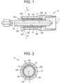
FIG. 1 is a cross-sectional view of a linear guide mechanism with one bushing and two liners, according to an embodiment of the present invention; -
FIG. 2 is a cross-sectional view of the linear guide mechanism ofFIG. 1 taken across Section 2-2; -
FIG. 3A is a cross-sectional view of the linear guide mechanism ofFIG. 1 shown with the shaft removed; -
FIG. 3B is a cross-sectional view of the linear guide mechanism ofFIG. 1 shown with the shaft removed and with two bushings; -
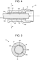
FIG. 4 is a cross-sectional view of the linear guide mechanism according to another embodiment of the present invention; -
FIG. 5 is a cross-sectional view of the linear guide mechanism ofFIG. 4 take across Section 5-5; -
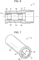
FIG. 6 is a cross-sectional view of the linear guide mechanism ofFIG. 4 shown with the shaft removed; -
FIG. 7 is a perspective view of the bushing ofFIG. 1 shown with a groove therein; -
FIG. 8 is a phantom view of the bushing ofFIG. 7 ; -
FIG. 9 is a schematic view of a cross-section of the self-lubricating liner; and -
FIG. 10 is an illustration of various lattice structures suitable for making up the bushing. - As shown in
FIGs. 1-3A , alinear guide mechanism 10 for a reciprocating container forming apparatus is provided. Thelinear guide mechanism 10 includes ahousing 12 having aninside housing surface 12E that defines abore 12H extending through thehousing 12 coaxial with a longitudinal axis L. In some embodiments, as shown inFigs. 1-2 , ashaft 30 is disposed at least partially inside thebore 12H and is reciprocatably (i.e., back and forth oscillatory motion) and linearly moveable in thebore 12H along the longitudinal axis L. Theshaft 30 has anexterior shaft surface 30E. - Two self-
lubricating liners 40, each having an annular configuration, are disposed in thebore 12H between theinside housing surface 12E and theexterior shaft surface 30E. The self-lubricating liners 40 are spaced apart from each other. Each self-lubricatingliner 40 has aninside liner surface 40E that is in sliding engagement with theexterior shaft surface 30E of theshaft 30. Each self-lubricatingliner 40 has anexterior liner surface 40F. In other embodiments, there are more than two self-lubricating liners 40. - The
linear guide mechanism 10 further includes abushing 20, which has an annular configuration and is disposed in thebore 12H. Thebushing 20 has anexterior bushing surface 20F and aninside bushing surface 20E. Theexterior bushing surface 20F is secured to theinside housing surface 12E. Theexterior liner surface 40F is secured to theinside bushing surface 20E. In some embodiments, thebushing 20 is press fit into thehousing 12. In some embodiments, each axial end of thebushing 20 is axially aligned with an axial end of a respective self-lubricatingliner 40. In some embodiments, the self-lubricating liners 40 are disposed entirely inside thebushing 20. The position of the self-lubricating liners 40 as shown inFigs. 1-3A is advantageous for maintaining functional stiffness of thebushing 20 for alignment and positional tolerance, while serving to reduce the frictional drag on theshaft 30. The surface area of theinside liner surface 40E influences the contact pressures experienced by the self-lubricating liners 40. - In some embodiments, several
smaller bushings 20 are installed instead of onelarge bushing 20, e.g., to control the contact area of the self-lubricating liners 40 or to reduced system weight. For example, referring to the embodiment ofFIG. 3B , thelinear guide mechanism 10 includes twobushings 20 spaced apart from one another. In some embodiments, thebushings 20 and the self-lubricating liners 40 are of the same length. In some embodiments, one of thebushings 20 is axially aligned with one of the self-lubricating liners 40, and theother bushing 20 is axially aligned with the other self-lubricatingliner 40. In other embodiments, more than twobushings 20 spaced apart from one another are used. - Some embodiments of the
linear guide mechanism 10 lacks thebushing 20. For example, inFIGs. 4-6 , there is nobushing 20. Instead, the self-lubricatingliner 40 is adhered directly to theinside housing surface 12E. - As shown in
FIGs. 7-8 , in some embodiments, thebushing 20 has agroove 20G extending axially along theinside bushing surface 20E and radially outward towards theexterior bushing surface 20F. Thegroove 20G radially terminates between theinside bushing surface 20E and theexterior bushing surface 20F. In some embodiments, thegroove 20G has rounded ends. In some embodiments, thegroove 20G extends into the self-lubricatingliner 40. In some embodiments, thegroove 20G is configured to receive an anti-rotation device. For example, in some embodiments, thegroove 20G is a keyway used for an anti-rotation device to keep theshaft 30 from rotating in thehousing 12. In some embodiments, thegroove 20G is configured to convey a fluid such as a coolant medium or lubricant. In some embodiments, thebushing 20 also has alip 20L for receiving or compressing a seal. - The self-lubricating
liner 40 is able to withstand heat generated from loading and movement conditions. Referring toFIG. 9 , in some embodiments, the self-lubricatingliner 40 includes polytetrafluoroethylene mono-filament fibers support fibers resin 84. In some embodiments, the polytetrafluoroethylene mono-filament fibers support fibers resin 84 includes polyester, epoxy, phenolic, urethane, polyimide, polyamide, acrylics, cyanoacrylates, silicones, polysulfides, anaerobics, elastomeric adhesives, or other suitable resins. In some embodiments, the self-lubricatingliner 40 includes additives for enhancing composite performance. - In some embodiments, the self-lubricating
liner 40 has a predetermined axial length configured to maintain contact pressure between theinside liner surface 40E and theexterior shaft surface 30E at less than 2 ksi. In some embodiments, the self-lubricatingliner 40 has a radial thickness of 0.010-0.040 inches in the original as installed state, before operation. In some embodiments, the self-lubricatingliner 40 has a dynamic coefficient of friction of 0.02 to 0.06 when contact pressure between theinside liner surface 40E and theexterior shaft surface 30E is less than 2 ksi and a relative speed between theinside liner surface 40E and theexterior shaft surface 30E is 30 to 100 inches per second. In some embodiments, the self-lubricatingliner 40 is configured to withstand temperatures of up to 200 to 300 degrees Fahrenheit. In some embodiments, the self-lubricatingliner 40 is capable of maintaining concentricity tolerances of theshaft 30 relative to the self-lubricatingliner 40. Specifically, in some embodiments, the self-lubricatingliner 40 wears less than seven thousandths of an inch in one year of continuous linear sliding operation of theshaft 30 within the self-lubricatingliner 40. Seven thousandths of an inch represents about 50-80 percent of the original thickness of theliner 40. - In some embodiments, the
bushing 20 includes at least one of an aluminum alloy, a titanium alloy, a bronze alloy, a beryllium alloy, and a magnesium alloy. In some embodiments, thebushing 20 includes a lattice or honeycomb structure. In some embodiments, the lattice or honeycomb structure is manufactured by a 3D printing process. In some embodiments, thebushing 20 is lightweight to help minimize the weight of thelinear guide mechanism 10. Minimizing the weight reduces the power needed to run the machine having thelinear guide mechanism 10. In some embodiments, minimization of the weight of thelinear guide mechanism 10 is achieved by: using lightweight materials such as aluminum or titanium that without the self-lubricatingliner 40 would have undesirable friction and wear performance; incorporating weight reduced geometries such as honeycomb 3D printed materials that would otherwise not be appropriate for a sliding bushing; or integrating thebushing 20 and thehousing 12 into a single component in which the self-lubricatingliner 40 is applied directly to thehousing 12 to reduce potential tolerance stack-up. -
FIG. 10 shows various examples of lattice structures suitable for making up thebushing 20. In one example, alattice structure 30" hassupport members 32". The distribution of thesupport members 32" is such that there is a higher concentration of thesupport members 32" at afirst end 30A" than at asecond end 30B". That is, the spaces 34' between thesupport members 32" increase in volume moving from thefirst end 30A" to thesecond end 30B". In the same manner, in some embodiments, the distribution ofsupport members 32" making up thebushing 20 is such that there is a higher concentration of thesupport members 32" at locations in thebushing 20 where stress is likely to be high. For example, in some embodiments, there is a relatively high concentration of thesupport members 32" in thebushing 20 proximate the interface between thebushing 20 and the self-lubricatingliner 40. - In another example shown in
FIG. 10 , lattice structure 30Q3 is made up of randomly arranged or pseudo-randomly arranged support members 32Q3. Similarly, in yet another example, lattice structure 30Q4 is made up of randomly arranged or pseudo-randomly arranged support members 32Q4. Other examples of lattice structures include lattice structure 30Q5, lattice structure 30Q6, and lattice structure 30Q7. In various embodiments, thebushing 20 is made up of any one or any combination of any two or more oflattice structure 30", lattice structure 30Q3, lattice structure 30Q4, lattice structure 30Q5, lattice structure 30Q6, and lattice structure 30Q7. - The
linear guide mechanism 10 according to the present disclosure has the advantage of providing for a grease free assembly, which helps to reduce grease related issues like contamination adhesion or food contamination. Thelinear guide mechanism 10 according to the present disclosure is capable of withstanding speeds and heat generated in sustained canning and bottling operations. - While the present disclosure has been described with reference to various exemplary embodiments, it will be understood by those skilled in the art that various changes may be made and equivalents may be substituted for elements thereof. In addition, many modifications may be made to adapt a particular situation or material to the teachings of the invention. Therefore, it is intended that the invention is limited by the scope of the appended claims.
Claims (14)
- A linear guide mechanism (10) for a reciprocating container forming apparatus, the linear guide mechanism (10) comprising:a housing (12) having an inside housing surface (12E) that defines a bore (12H) extending through the housing (12) coaxial with a longitudinal axis (L);a shaft (30) disposed at least partially in the bore (12H) and being reciprocatably and linearly moveable in the bore (12H) along the longitudinal axis (L), the shaft (30) having an exterior shaft surface (30E); anda self-lubricating liner (40) disposed in the bore (12H) between the inside housing surface (12E) and the exterior shaft surface (30E), the self-lubricating liner (40) having an inside liner surface (40E) that is in sliding engagement with the exterior shaft surface (30E) of the shaft (30) and the self-lubricating liner (40) having an exterior liner surface (40F), characterised in that the linear guide mechanism further comprisesanother self-lubricating liner (40) spaced apart from the self-lubricating liner (40).
- The linear guide mechanism (10) of claim 1, wherein the self-lubricating liner (40) is adhered to the inside housing surface (12E).
- The linear guide mechanism (10) of any of the preceding claims, further comprising:a bushing (20) disposed in the bore (12H), the bushing (20) having an exterior bushing surface (20F) and an inside bushing surface (20E), the exterior bushing surface (20F) being secured to the inside housing surface (12E),wherein the exterior liner surface (40F) is secured to the inside bushing surface (20E).
- The linear guide mechanism (10) of any of the preceding claims, wherein the self-lubricating liner (40) has an annular configuration.
- The linear guide mechanism (10) of claim 3, wherein the bushing (20) has an annular configuration.
- The linear guide mechanism (10) of any of the preceding claims, wherein the self-lubricating liner (40) has a dynamic coefficient of friction of 0.02 to 0.06 when contact pressure between the inside liner surface (40E) and the exterior shaft surface (30E) is less than 2 ksi and a relative speed between the inside liner surface (40E) and the exterior shaft surface (30E) is up to 100 inches per second.
- The linear guide mechanism (10) of claim 6, wherein the self-lubricating liner (40) is configured to withstand temperatures of up to 300 degrees Fahrenheit.
- The linear guide mechanism (10) of any of the preceding claims, wherein the self-lubricating liner (40) has a predetermined axial length configured to maintain contact pressure between the inside liner surface (40E) and the exterior shaft surface (30E) at less than 2 ksi.
- The linear guide mechanism (10) of claim 3, further comprising another bushing (20) spaced apart from the bushing (20).
- The linear guide mechanism (10) of claim 3, wherein the bushing (20) comprises a groove (20G) extending axially along the inside bushing surface (20E) and radially outward towards the exterior bushing surface (20F), the groove (20G) radially terminating between the inside bushing surface (20E) and the exterior bushing surface (20F).
- The linear guide mechanism (10) of claim 10, wherein the groove (20G) extends into the self-lubricating liner (40).
- The linear guide mechanism (10) of any of claims 10-11, wherein the groove (20G) is configured to receive an anti-rotation device.
- The linear guide mechanism (10) of any of claims 10-11, wherein the groove (20G) is configured to convey a fluid therein.
- The linear guide mechanism (10) of any of the preceding claims, wherein the self-lubricating liner (40) is configured to wear less than seven thousandths of an inch during one year of continuous linear sliding operation of the shaft (30) in the self-lubricating liner (40).
Applications Claiming Priority (1)
| Application Number | Priority Date | Filing Date | Title |
|---|---|---|---|
| US202163232462P | 2021-08-12 | 2021-08-12 |
Publications (2)
| Publication Number | Publication Date |
|---|---|
| EP4134559A1 EP4134559A1 (en) | 2023-02-15 |
| EP4134559B1 true EP4134559B1 (en) | 2024-10-02 |
Family
ID=82846351
Family Applications (1)
| Application Number | Title | Priority Date | Filing Date |
|---|---|---|---|
| EP22188963.7A Active EP4134559B1 (en) | 2021-08-12 | 2022-08-05 | Self lubricating linear guide bushings for reciprocating canning and bottling machinery |
Country Status (2)
| Country | Link |
|---|---|
| US (1) | US12297864B2 (en) |
| EP (1) | EP4134559B1 (en) |
Family Cites Families (24)
| Publication number | Priority date | Publication date | Assignee | Title |
|---|---|---|---|---|
| FR1503644A (en) | 1966-09-22 | 1967-12-01 | Mecaplast Sa | Device for blowing and filling hollow bodies produced by the extrusion blow molding process |
| FR1581682A (en) | 1968-07-15 | 1969-09-19 | ||
| AU547641B2 (en) | 1981-08-17 | 1985-10-31 | Duriron Co. Inc., The | Ptfe lined bearing or guide |
| GB2235736B (en) * | 1989-08-09 | 1993-09-15 | Nippon Seiko Kk | Bearing with dynamic pressure grooves and method for manufacturing the same |
| US5417499A (en) * | 1993-03-31 | 1995-05-23 | Eagle-Picher Industries, Inc. | Fabric lined bushing |
| DE19524968A1 (en) | 1995-07-08 | 1997-01-16 | Glyco Metall Werke | Plain bearing material and its use |
| DE19851759C2 (en) * | 1998-11-10 | 2000-10-12 | Ks Gleitlager Gmbh | Rolled plain bearing bush |
| US6799894B2 (en) | 2002-06-14 | 2004-10-05 | Anchor Lamina, Inc. | Bushing |
| JP4540612B2 (en) | 2004-01-29 | 2010-09-08 | Thk株式会社 | Cage-fixed linear guide device |
| CN1749583A (en) * | 2004-09-13 | 2006-03-22 | Smc株式会社 | with guide cylinder |
| US8650756B2 (en) * | 2006-10-27 | 2014-02-18 | University Of Virginia Patent Foundation | Manufacture of lattice truss structures from monolithic materials |
| JP5595705B2 (en) * | 2009-09-30 | 2014-09-24 | オイレス工業株式会社 | Sliding face material and multilayer sliding member provided with the sliding face material |
| CN103492738B (en) | 2011-04-26 | 2014-11-05 | 千住金属工业株式会社 | Sliding member |
| CN106870349A (en) * | 2012-03-27 | 2017-06-20 | Ntn株式会社 | Composite sliding bearing, bracket guiding piece, variable capacity type axial poiston pump |
| DE102014224299A1 (en) | 2014-11-27 | 2016-06-02 | Aktiebolaget Skf | Component with at least one sliding layer and method for producing the component |
| EP3176463B1 (en) | 2015-03-05 | 2018-09-26 | Roller Bearing Company of America, Inc. | Rotation rod assembly with self lubricating liner or grooved bushings |
| US10557464B2 (en) * | 2015-12-23 | 2020-02-11 | Emerson Climate Technologies, Inc. | Lattice-cored additive manufactured compressor components with fluid delivery features |
| US11473626B2 (en) * | 2016-05-16 | 2022-10-18 | Roller Bearing Company Of America, Inc. | Bearing system with self-lubrication features, seals, grooves and slots for maintenance-free operation |
| EP3403744A1 (en) | 2017-05-19 | 2018-11-21 | Siemens Aktiengesellschaft | Machine component made by additive manufacturing |
| WO2019117244A1 (en) | 2017-12-15 | 2019-06-20 | 千住金属工業株式会社 | Sliding member and bearing |
| DE102017130770A1 (en) | 2017-12-20 | 2019-06-27 | Khs Gmbh | Spindle shaft unit for a device for twist-closing containers with a screw cap |
| DE102018200344A1 (en) | 2018-01-11 | 2019-07-11 | Contitech Luftfedersysteme Gmbh | Hydraulic bearing bush |
| IT201800007189A1 (en) | 2018-07-13 | 2020-01-13 | LINEAR GUIDE AND THE PRODUCTION PROCESS OF A LINEAR GUIDE | |
| JP6677896B1 (en) * | 2019-06-12 | 2020-04-08 | 千住金属工業株式会社 | Sliding members and bearings |
-
2022
- 2022-08-05 EP EP22188963.7A patent/EP4134559B1/en active Active
- 2022-08-05 US US17/881,953 patent/US12297864B2/en active Active
Also Published As
| Publication number | Publication date |
|---|---|
| US20230048155A1 (en) | 2023-02-16 |
| EP4134559A1 (en) | 2023-02-15 |
| US12297864B2 (en) | 2025-05-13 |
Similar Documents
| Publication | Publication Date | Title |
|---|---|---|
| US5549394A (en) | Bearing arrangement having a polyimide graphite-fiber reinforced composite embedded therein | |
| US7114605B2 (en) | Double or multiple disk coupling device and disk arrangement therefor | |
| EP3094428B1 (en) | Linear actuator assembly | |
| EP1934474B1 (en) | Combined labyrinth seal and screw-type gasket bearing sealing arrangement | |
| CN101395397B (en) | Device for actuating a clutch | |
| EP0411695A2 (en) | A magnetic bearing-shaft assembly having a bearing to support the shaft in the event of failure of the magnetic bearing | |
| US9169907B2 (en) | Spindle drive | |
| EP3869054B1 (en) | Angular ball bearing | |
| CN101400453B (en) | Component, especially a preform, comprising a coating | |
| US20210310372A1 (en) | Exhaust gas turbocharger having a hydrodynamic plain bearing or a hydrodynamic plain bearing | |
| EP4134559A1 (en) | Self lubricating linear guide bushings for reciprocating canning and bottling machinery | |
| CN106286628A (en) | Assembly for the lock unit of shift transmission mechanism | |
| US8109244B1 (en) | Crankdisk bearing alternatives for the Waissi type opposed piston internal combustion engine | |
| US20090282972A1 (en) | Composite piston for a motor vehicle transmission | |
| US20090293652A1 (en) | Apparatus, Method and System For Reducing Adhesive Wear On A Power Take-Off Shaft | |
| JP7222834B2 (en) | electric brake device | |
| US5564333A (en) | Spring biased flywheel | |
| WO2003042548A1 (en) | Hydraulic and pneumatic cylinders with polymer coating | |
| EP3658793B1 (en) | Fluid cushion guiding device | |
| CN111075909B (en) | Through shaft power output shaft gear box and machinery for installing through shaft power output shaft gear box | |
| RU2112159C1 (en) | Sliding bearing | |
| CN1114018A (en) | Static balance combined high pressure rotary shaft oil seal | |
| CN215214658U (en) | A non-contact sealing end cover of a reducer input shaft | |
| KR100604725B1 (en) | Heavy torsional vibration damper with intermediate elements and method of replacing component therof | |
| EP2552615B1 (en) | Self-lubricating dwell cam driver |
Legal Events
| Date | Code | Title | Description |
|---|---|---|---|
| PUAI | Public reference made under article 153(3) epc to a published international application that has entered the european phase |
Free format text: ORIGINAL CODE: 0009012 |
|
| STAA | Information on the status of an ep patent application or granted ep patent |
Free format text: STATUS: THE APPLICATION HAS BEEN PUBLISHED |
|
| AK | Designated contracting states |
Kind code of ref document: A1 Designated state(s): AL AT BE BG CH CY CZ DE DK EE ES FI FR GB GR HR HU IE IS IT LI LT LU LV MC MK MT NL NO PL PT RO RS SE SI SK SM TR |
|
| STAA | Information on the status of an ep patent application or granted ep patent |
Free format text: STATUS: REQUEST FOR EXAMINATION WAS MADE |
|
| 17P | Request for examination filed |
Effective date: 20230815 |
|
| RBV | Designated contracting states (corrected) |
Designated state(s): AL AT BE BG CH CY CZ DE DK EE ES FI FR GB GR HR HU IE IS IT LI LT LU LV MC MK MT NL NO PL PT RO RS SE SI SK SM TR |
|
| GRAP | Despatch of communication of intention to grant a patent |
Free format text: ORIGINAL CODE: EPIDOSNIGR1 |
|
| STAA | Information on the status of an ep patent application or granted ep patent |
Free format text: STATUS: GRANT OF PATENT IS INTENDED |
|
| INTG | Intention to grant announced |
Effective date: 20240325 |
|
| GRAS | Grant fee paid |
Free format text: ORIGINAL CODE: EPIDOSNIGR3 |
|
| GRAA | (expected) grant |
Free format text: ORIGINAL CODE: 0009210 |
|
| STAA | Information on the status of an ep patent application or granted ep patent |
Free format text: STATUS: THE PATENT HAS BEEN GRANTED |
|
| AK | Designated contracting states |
Kind code of ref document: B1 Designated state(s): AL AT BE BG CH CY CZ DE DK EE ES FI FR GB GR HR HU IE IS IT LI LT LU LV MC MK MT NL NO PL PT RO RS SE SI SK SM TR |
|
| REG | Reference to a national code |
Ref country code: GB Ref legal event code: FG4D |
|
| REG | Reference to a national code |
Ref country code: CH Ref legal event code: EP |
|
| REG | Reference to a national code |
Ref country code: DE Ref legal event code: R096 Ref document number: 602022006473 Country of ref document: DE |
|
| REG | Reference to a national code |
Ref country code: IE Ref legal event code: FG4D |
|
| P01 | Opt-out of the competence of the unified patent court (upc) registered |
Free format text: CASE NUMBER: APP_60611/2024 Effective date: 20241111 |
|
| P02 | Opt-out of the competence of the unified patent court (upc) changed |
Free format text: CASE NUMBER: APP_60618/2024 Effective date: 20241111 |
|
| REG | Reference to a national code |
Ref country code: LT Ref legal event code: MG9D |
|
| REG | Reference to a national code |
Ref country code: NL Ref legal event code: MP Effective date: 20241002 |
|
| REG | Reference to a national code |
Ref country code: AT Ref legal event code: MK05 Ref document number: 1728706 Country of ref document: AT Kind code of ref document: T Effective date: 20241002 |
|
| PG25 | Lapsed in a contracting state [announced via postgrant information from national office to epo] |
Ref country code: NL Free format text: LAPSE BECAUSE OF FAILURE TO SUBMIT A TRANSLATION OF THE DESCRIPTION OR TO PAY THE FEE WITHIN THE PRESCRIBED TIME-LIMIT Effective date: 20241002 |
|
| PG25 | Lapsed in a contracting state [announced via postgrant information from national office to epo] |
Ref country code: NL Free format text: LAPSE BECAUSE OF FAILURE TO SUBMIT A TRANSLATION OF THE DESCRIPTION OR TO PAY THE FEE WITHIN THE PRESCRIBED TIME-LIMIT Effective date: 20241002 |
|
| PG25 | Lapsed in a contracting state [announced via postgrant information from national office to epo] |
Ref country code: IS Free format text: LAPSE BECAUSE OF FAILURE TO SUBMIT A TRANSLATION OF THE DESCRIPTION OR TO PAY THE FEE WITHIN THE PRESCRIBED TIME-LIMIT Effective date: 20250202 Ref country code: PT Free format text: LAPSE BECAUSE OF FAILURE TO SUBMIT A TRANSLATION OF THE DESCRIPTION OR TO PAY THE FEE WITHIN THE PRESCRIBED TIME-LIMIT Effective date: 20250203 Ref country code: HR Free format text: LAPSE BECAUSE OF FAILURE TO SUBMIT A TRANSLATION OF THE DESCRIPTION OR TO PAY THE FEE WITHIN THE PRESCRIBED TIME-LIMIT Effective date: 20241002 |
|
| PG25 | Lapsed in a contracting state [announced via postgrant information from national office to epo] |
Ref country code: FI Free format text: LAPSE BECAUSE OF FAILURE TO SUBMIT A TRANSLATION OF THE DESCRIPTION OR TO PAY THE FEE WITHIN THE PRESCRIBED TIME-LIMIT Effective date: 20241002 |
|
| PG25 | Lapsed in a contracting state [announced via postgrant information from national office to epo] |
Ref country code: BG Free format text: LAPSE BECAUSE OF FAILURE TO SUBMIT A TRANSLATION OF THE DESCRIPTION OR TO PAY THE FEE WITHIN THE PRESCRIBED TIME-LIMIT Effective date: 20241002 |
|
| PG25 | Lapsed in a contracting state [announced via postgrant information from national office to epo] |
Ref country code: ES Free format text: LAPSE BECAUSE OF FAILURE TO SUBMIT A TRANSLATION OF THE DESCRIPTION OR TO PAY THE FEE WITHIN THE PRESCRIBED TIME-LIMIT Effective date: 20241002 |
|
| PG25 | Lapsed in a contracting state [announced via postgrant information from national office to epo] |
Ref country code: NO Free format text: LAPSE BECAUSE OF FAILURE TO SUBMIT A TRANSLATION OF THE DESCRIPTION OR TO PAY THE FEE WITHIN THE PRESCRIBED TIME-LIMIT Effective date: 20250102 |
|
| PG25 | Lapsed in a contracting state [announced via postgrant information from national office to epo] |
Ref country code: AT Free format text: LAPSE BECAUSE OF FAILURE TO SUBMIT A TRANSLATION OF THE DESCRIPTION OR TO PAY THE FEE WITHIN THE PRESCRIBED TIME-LIMIT Effective date: 20241002 Ref country code: LV Free format text: LAPSE BECAUSE OF FAILURE TO SUBMIT A TRANSLATION OF THE DESCRIPTION OR TO PAY THE FEE WITHIN THE PRESCRIBED TIME-LIMIT Effective date: 20241002 Ref country code: GR Free format text: LAPSE BECAUSE OF FAILURE TO SUBMIT A TRANSLATION OF THE DESCRIPTION OR TO PAY THE FEE WITHIN THE PRESCRIBED TIME-LIMIT Effective date: 20250103 |
|
| PG25 | Lapsed in a contracting state [announced via postgrant information from national office to epo] |
Ref country code: CZ Free format text: LAPSE BECAUSE OF FAILURE TO SUBMIT A TRANSLATION OF THE DESCRIPTION OR TO PAY THE FEE WITHIN THE PRESCRIBED TIME-LIMIT Effective date: 20241002 Ref country code: PL Free format text: LAPSE BECAUSE OF FAILURE TO SUBMIT A TRANSLATION OF THE DESCRIPTION OR TO PAY THE FEE WITHIN THE PRESCRIBED TIME-LIMIT Effective date: 20241002 |
|
| PG25 | Lapsed in a contracting state [announced via postgrant information from national office to epo] |
Ref country code: RS Free format text: LAPSE BECAUSE OF FAILURE TO SUBMIT A TRANSLATION OF THE DESCRIPTION OR TO PAY THE FEE WITHIN THE PRESCRIBED TIME-LIMIT Effective date: 20250102 |
|
| PG25 | Lapsed in a contracting state [announced via postgrant information from national office to epo] |
Ref country code: SM Free format text: LAPSE BECAUSE OF FAILURE TO SUBMIT A TRANSLATION OF THE DESCRIPTION OR TO PAY THE FEE WITHIN THE PRESCRIBED TIME-LIMIT Effective date: 20241002 |
|
| REG | Reference to a national code |
Ref country code: DE Ref legal event code: R097 Ref document number: 602022006473 Country of ref document: DE |
|
| PG25 | Lapsed in a contracting state [announced via postgrant information from national office to epo] |
Ref country code: DK Free format text: LAPSE BECAUSE OF FAILURE TO SUBMIT A TRANSLATION OF THE DESCRIPTION OR TO PAY THE FEE WITHIN THE PRESCRIBED TIME-LIMIT Effective date: 20241002 |
|
| PG25 | Lapsed in a contracting state [announced via postgrant information from national office to epo] |
Ref country code: EE Free format text: LAPSE BECAUSE OF FAILURE TO SUBMIT A TRANSLATION OF THE DESCRIPTION OR TO PAY THE FEE WITHIN THE PRESCRIBED TIME-LIMIT Effective date: 20241002 |
|
| PG25 | Lapsed in a contracting state [announced via postgrant information from national office to epo] |
Ref country code: RO Free format text: LAPSE BECAUSE OF FAILURE TO SUBMIT A TRANSLATION OF THE DESCRIPTION OR TO PAY THE FEE WITHIN THE PRESCRIBED TIME-LIMIT Effective date: 20241002 |
|
| PG25 | Lapsed in a contracting state [announced via postgrant information from national office to epo] |
Ref country code: SK Free format text: LAPSE BECAUSE OF FAILURE TO SUBMIT A TRANSLATION OF THE DESCRIPTION OR TO PAY THE FEE WITHIN THE PRESCRIBED TIME-LIMIT Effective date: 20241002 |
|
| PG25 | Lapsed in a contracting state [announced via postgrant information from national office to epo] |
Ref country code: IT Free format text: LAPSE BECAUSE OF FAILURE TO SUBMIT A TRANSLATION OF THE DESCRIPTION OR TO PAY THE FEE WITHIN THE PRESCRIBED TIME-LIMIT Effective date: 20241002 |
|
| PLBE | No opposition filed within time limit |
Free format text: ORIGINAL CODE: 0009261 |
|
| STAA | Information on the status of an ep patent application or granted ep patent |
Free format text: STATUS: NO OPPOSITION FILED WITHIN TIME LIMIT |
|
| PG25 | Lapsed in a contracting state [announced via postgrant information from national office to epo] |
Ref country code: SE Free format text: LAPSE BECAUSE OF FAILURE TO SUBMIT A TRANSLATION OF THE DESCRIPTION OR TO PAY THE FEE WITHIN THE PRESCRIBED TIME-LIMIT Effective date: 20241002 |
|
| 26N | No opposition filed |
Effective date: 20250703 |
|
| PGFP | Annual fee paid to national office [announced via postgrant information from national office to epo] |
Ref country code: DE Payment date: 20250827 Year of fee payment: 4 |
|
| REG | Reference to a national code |
Ref country code: CH Ref legal event code: H13 Free format text: ST27 STATUS EVENT CODE: U-0-0-H10-H13 (AS PROVIDED BY THE NATIONAL OFFICE) Effective date: 20260324 |
|
| PG25 | Lapsed in a contracting state [announced via postgrant information from national office to epo] |
Ref country code: MC Free format text: LAPSE BECAUSE OF FAILURE TO SUBMIT A TRANSLATION OF THE DESCRIPTION OR TO PAY THE FEE WITHIN THE PRESCRIBED TIME-LIMIT Effective date: 20241002 |
|
| PG25 | Lapsed in a contracting state [announced via postgrant information from national office to epo] |
Ref country code: LU Free format text: LAPSE BECAUSE OF NON-PAYMENT OF DUE FEES Effective date: 20250805 |
|
| PG25 | Lapsed in a contracting state [announced via postgrant information from national office to epo] |
Ref country code: CH Free format text: LAPSE BECAUSE OF NON-PAYMENT OF DUE FEES Effective date: 20250831 |
|
| REG | Reference to a national code |
Ref country code: BE Ref legal event code: MM Effective date: 20250831 |
|
| PG25 | Lapsed in a contracting state [announced via postgrant information from national office to epo] |
Ref country code: LT Free format text: LAPSE BECAUSE OF FAILURE TO SUBMIT A TRANSLATION OF THE DESCRIPTION OR TO PAY THE FEE WITHIN THE PRESCRIBED TIME-LIMIT Effective date: 20241002 |
|
| PG25 | Lapsed in a contracting state [announced via postgrant information from national office to epo] |
Ref country code: BE Free format text: LAPSE BECAUSE OF NON-PAYMENT OF DUE FEES Effective date: 20250831 Ref country code: IE Free format text: LAPSE BECAUSE OF NON-PAYMENT OF DUE FEES Effective date: 20250805 |
|
| PG25 | Lapsed in a contracting state [announced via postgrant information from national office to epo] |
Ref country code: FR Free format text: LAPSE BECAUSE OF NON-PAYMENT OF DUE FEES Effective date: 20250831 |