EP4134556A1 - Fastening assembly - Google Patents
Fastening assembly Download PDFInfo
- Publication number
- EP4134556A1 EP4134556A1 EP22158234.9A EP22158234A EP4134556A1 EP 4134556 A1 EP4134556 A1 EP 4134556A1 EP 22158234 A EP22158234 A EP 22158234A EP 4134556 A1 EP4134556 A1 EP 4134556A1
- Authority
- EP
- European Patent Office
- Prior art keywords
- vertical beam
- movable part
- turnover
- transmission rod
- fastening assembly
- Prior art date
- Legal status (The legal status is an assumption and is not a legal conclusion. Google has not performed a legal analysis and makes no representation as to the accuracy of the status listed.)
- Granted
Links
- 230000007306 turnover Effects 0.000 claims abstract description 86
- 230000005540 biological transmission Effects 0.000 claims abstract description 35
- 230000009471 action Effects 0.000 claims abstract description 3
- 238000010586 diagram Methods 0.000 description 6
- 230000004048 modification Effects 0.000 description 2
- 238000012986 modification Methods 0.000 description 2
- 230000010485 coping Effects 0.000 description 1
- 230000003993 interaction Effects 0.000 description 1
- 239000013589 supplement Substances 0.000 description 1
Images


Classifications
-
- F—MECHANICAL ENGINEERING; LIGHTING; HEATING; WEAPONS; BLASTING
- F16—ENGINEERING ELEMENTS AND UNITS; GENERAL MEASURES FOR PRODUCING AND MAINTAINING EFFECTIVE FUNCTIONING OF MACHINES OR INSTALLATIONS; THERMAL INSULATION IN GENERAL
- F16B—DEVICES FOR FASTENING OR SECURING CONSTRUCTIONAL ELEMENTS OR MACHINE PARTS TOGETHER, e.g. NAILS, BOLTS, CIRCLIPS, CLAMPS, CLIPS OR WEDGES; JOINTS OR JOINTING
- F16B13/00—Dowels or other devices fastened in walls or the like by inserting them in holes made therein for that purpose
- F16B13/04—Dowels or other devices fastened in walls or the like by inserting them in holes made therein for that purpose with parts gripping in the hole or behind the reverse side of the wall after inserting from the front
- F16B13/08—Dowels or other devices fastened in walls or the like by inserting them in holes made therein for that purpose with parts gripping in the hole or behind the reverse side of the wall after inserting from the front with separate or non-separate gripping parts moved into their final position in relation to the body of the device without further manual operation
- F16B13/0808—Dowels or other devices fastened in walls or the like by inserting them in holes made therein for that purpose with parts gripping in the hole or behind the reverse side of the wall after inserting from the front with separate or non-separate gripping parts moved into their final position in relation to the body of the device without further manual operation by a toggle-mechanism
-
- F—MECHANICAL ENGINEERING; LIGHTING; HEATING; WEAPONS; BLASTING
- F16—ENGINEERING ELEMENTS AND UNITS; GENERAL MEASURES FOR PRODUCING AND MAINTAINING EFFECTIVE FUNCTIONING OF MACHINES OR INSTALLATIONS; THERMAL INSULATION IN GENERAL
- F16B—DEVICES FOR FASTENING OR SECURING CONSTRUCTIONAL ELEMENTS OR MACHINE PARTS TOGETHER, e.g. NAILS, BOLTS, CIRCLIPS, CLAMPS, CLIPS OR WEDGES; JOINTS OR JOINTING
- F16B13/00—Dowels or other devices fastened in walls or the like by inserting them in holes made therein for that purpose
- F16B13/12—Separate metal or non-separate or non-metal dowel sleeves fastened by inserting the screw, nail or the like
- F16B13/124—Separate metal or non-separate or non-metal dowel sleeves fastened by inserting the screw, nail or the like fastened by inserting a threaded element, e.g. screw or bolt
-
- F—MECHANICAL ENGINEERING; LIGHTING; HEATING; WEAPONS; BLASTING
- F16—ENGINEERING ELEMENTS AND UNITS; GENERAL MEASURES FOR PRODUCING AND MAINTAINING EFFECTIVE FUNCTIONING OF MACHINES OR INSTALLATIONS; THERMAL INSULATION IN GENERAL
- F16B—DEVICES FOR FASTENING OR SECURING CONSTRUCTIONAL ELEMENTS OR MACHINE PARTS TOGETHER, e.g. NAILS, BOLTS, CIRCLIPS, CLAMPS, CLIPS OR WEDGES; JOINTS OR JOINTING
- F16B13/00—Dowels or other devices fastened in walls or the like by inserting them in holes made therein for that purpose
- F16B13/001—Dowels or other devices fastened in walls or the like by inserting them in holes made therein for that purpose with means for preventing rotation of the dowel
-
- F—MECHANICAL ENGINEERING; LIGHTING; HEATING; WEAPONS; BLASTING
- F16—ENGINEERING ELEMENTS AND UNITS; GENERAL MEASURES FOR PRODUCING AND MAINTAINING EFFECTIVE FUNCTIONING OF MACHINES OR INSTALLATIONS; THERMAL INSULATION IN GENERAL
- F16B—DEVICES FOR FASTENING OR SECURING CONSTRUCTIONAL ELEMENTS OR MACHINE PARTS TOGETHER, e.g. NAILS, BOLTS, CIRCLIPS, CLAMPS, CLIPS OR WEDGES; JOINTS OR JOINTING
- F16B13/00—Dowels or other devices fastened in walls or the like by inserting them in holes made therein for that purpose
- F16B13/002—Dowels or other devices fastened in walls or the like by inserting them in holes made therein for that purpose self-cutting
-
- F—MECHANICAL ENGINEERING; LIGHTING; HEATING; WEAPONS; BLASTING
- F16—ENGINEERING ELEMENTS AND UNITS; GENERAL MEASURES FOR PRODUCING AND MAINTAINING EFFECTIVE FUNCTIONING OF MACHINES OR INSTALLATIONS; THERMAL INSULATION IN GENERAL
- F16B—DEVICES FOR FASTENING OR SECURING CONSTRUCTIONAL ELEMENTS OR MACHINE PARTS TOGETHER, e.g. NAILS, BOLTS, CIRCLIPS, CLAMPS, CLIPS OR WEDGES; JOINTS OR JOINTING
- F16B5/00—Joining sheets or plates, e.g. panels, to one another or to strips or bars parallel to them
- F16B5/06—Joining sheets or plates, e.g. panels, to one another or to strips or bars parallel to them by means of clamps or clips
- F16B5/0607—Joining sheets or plates, e.g. panels, to one another or to strips or bars parallel to them by means of clamps or clips joining sheets or plates to each other
- F16B5/0621—Joining sheets or plates, e.g. panels, to one another or to strips or bars parallel to them by means of clamps or clips joining sheets or plates to each other in parallel relationship
- F16B5/0642—Joining sheets or plates, e.g. panels, to one another or to strips or bars parallel to them by means of clamps or clips joining sheets or plates to each other in parallel relationship the plates being arranged one on top of the other and in full close contact with each other
-
- F—MECHANICAL ENGINEERING; LIGHTING; HEATING; WEAPONS; BLASTING
- F16—ENGINEERING ELEMENTS AND UNITS; GENERAL MEASURES FOR PRODUCING AND MAINTAINING EFFECTIVE FUNCTIONING OF MACHINES OR INSTALLATIONS; THERMAL INSULATION IN GENERAL
- F16B—DEVICES FOR FASTENING OR SECURING CONSTRUCTIONAL ELEMENTS OR MACHINE PARTS TOGETHER, e.g. NAILS, BOLTS, CIRCLIPS, CLAMPS, CLIPS OR WEDGES; JOINTS OR JOINTING
- F16B13/00—Dowels or other devices fastened in walls or the like by inserting them in holes made therein for that purpose
- F16B13/04—Dowels or other devices fastened in walls or the like by inserting them in holes made therein for that purpose with parts gripping in the hole or behind the reverse side of the wall after inserting from the front
- F16B13/06—Dowels or other devices fastened in walls or the like by inserting them in holes made therein for that purpose with parts gripping in the hole or behind the reverse side of the wall after inserting from the front combined with expanding sleeve
- F16B13/061—Dowels or other devices fastened in walls or the like by inserting them in holes made therein for that purpose with parts gripping in the hole or behind the reverse side of the wall after inserting from the front combined with expanding sleeve of the buckling type
-
- F—MECHANICAL ENGINEERING; LIGHTING; HEATING; WEAPONS; BLASTING
- F16—ENGINEERING ELEMENTS AND UNITS; GENERAL MEASURES FOR PRODUCING AND MAINTAINING EFFECTIVE FUNCTIONING OF MACHINES OR INSTALLATIONS; THERMAL INSULATION IN GENERAL
- F16B—DEVICES FOR FASTENING OR SECURING CONSTRUCTIONAL ELEMENTS OR MACHINE PARTS TOGETHER, e.g. NAILS, BOLTS, CIRCLIPS, CLAMPS, CLIPS OR WEDGES; JOINTS OR JOINTING
- F16B37/00—Nuts or like thread-engaging members
- F16B37/04—Devices for fastening nuts to surfaces, e.g. sheets, plates
- F16B37/041—Releasable devices
- F16B37/043—Releasable devices with snap action
Definitions
- the disclosure relates to the technical field of connection, in particular to a fastening assembly.
- connection of two objects is usually realized by bolts and nuts.
- the bolts are threaded through the mounting holes of the two objects, and the user correspondingly sets the nuts on the bolts to complete the connection of the two objects.
- artificially aligning the set nuts will increase the labor intensity and affect the use experience of users.
- the disclosure aims to solve at least one of the technical problems existing in the prior art, and the disclosure provides a fastening assembly, which can reduce the labor intensity of users and optimize the use experience of users.
- a fastening assembly including a mounting cylinder frame, a movable part, and a turnover part.
- the mounting cylinder frame is provided with a first vertical beam and a transmission rod
- the mounting cylinder frame is provided with a butting block at a top of the first vertical beam
- the transmission rod passes through the butting block
- a side wall of the first vertical beam is provided with a bulge.
- the movable part is connected with the transmission rod.
- the turnover part is arranged on the first vertical beam and is rotatably connected with the movable part, the turnover part is butted with the bulge, the turnover part is located between the butting block and the movable part, and the turnover part has a vertical state and a horizontal state, wherein, the transmission rod is configured to drive the movable part to move along an axial direction of the first vertical beam, so as to drive the turnover part to switch between the horizontal state or the vertical state under an action of the bulge.
- the turnover part can be switched from the vertical state to the horizontal state only through the transmission rod, wherein the turnover part in the horizontal state and the butting block together clamp the two objects, so as to complete the connection of the two objects.
- the above connection does not require the user to manually align the set nut. Therefore, the labor intensity of the user can be reduced to optimize the use experience.
- the movable part includes the movable part body and a connecting block.
- the movable part body is slidably connected with the first vertical beam, the movable part body is rotationally connected with the turnover part, and the movable part body is provided with a mounting cavity.
- the connecting block is embedded in the mounting cavity, and the connecting block is sleeved on the transmission rod and threaded with the transmission rod.
- the movable part body is provided with a connecting shaft
- the turnover part is provided with a guide slot
- the connecting shaft passes through the guide slot
- the connecting block partially extends out of the mounting cavity, and the turnover part is provided with a snap notch matched with the extending portion of the connecting block; and the extending portion of the connecting block is embedded in the snap notch when the turnover part is in a horizontal state.
- the movable part body is provided with an anti-falling block, and the anti-falling block is butted with the connecting block.
- the mounting cylinder frame is provided with a second vertical beam, the second vertical beam, the first vertical beam and the transmission rod are arranged side by side, and the second vertical beam is slidably connected with the movable part body.
- the first vertical beam is provided with a platform, and the turnover part in the vertical state is butted with the platform.
- the first vertical beam is provided with an avoidance hole, and the avoidance hole is arranged corresponding to the bulge.
- the first vertical beam is provided with a positioning block, the positioning block butts against a top of the movable part (200) when the turnover part (300) is in a vertical state.
- the turnover part is provided with anti-skid teeth; and the anti-skid teeth are facing the butting block when the turnover part is in a horizontal state.
- orientation or position relationship related to the orientation description is based on the orientation or position relationship shown in the attached drawings, only for the convenience of describing the disclosure and simplifying the description, rather than indicating or implying that the device or element must have a specific orientation, or being constructed and operated in a specific orientation. Therefore, it cannot be understood as a limitation of the present disclosure.
- an embodiment of the present disclosure relates to a fastening assembly, including a mounting cylinder frame 100, a movable part 200 and a turnover part 300.
- the mounting cylinder frame 100 is provided with a first vertical beam 111 and a transmission rod 121 which are arranged side by side.
- the mounting cylinder frame 100 is provided with a butting block 112 at the top of the first vertical beam 111, the transmission rod 121 passes through the butting block 112, and the side wall of the first vertical beam 111 is provided with a bulge 111A.
- the movable part 200 is connected with the transmission rod 121.
- the turnover part 300 is rotationally connected with the movable part 200.
- the turnover part 300 is butted with the bulge 111A, the turnover part 300 is located between the butting block 112 and the movable part 200, and the turnover part 300 has a vertical state and a horizontal state.
- the transmission rod 121 can drive the movable part 200 to move along the axial direction of the first vertical beam 111 to come close or move away from the butting block 112, so as to drive the turnover part 300 to turnover under the force of the bulge 111A, so as to switch between the horizontal state or the vertical state.
- the top projection of the turnover part 300 is in a U shape.
- the turnover part 300 includes a connecting arm 310 and two opposite turnover arms 320. Both ends of the connecting arm 310 are respectively connected with the two turnover arms 320. Both sides of the first vertical beam 111 are provided with bulges 111A, and the two bulges 111A are butted with the inner walls of the two turnover arms 320 one by one.
- the turnover arm 320 is rotatably connected with the movable part 200, wherein the connecting arm 310 and the two turnover arms 320 are an integrated structure.
- the transmission rod 121 can drive the movable part 200 to move in the direction close to the butting block 112.
- the movable part 200 moving close to the butting block 112 pushes the rotating arm 320 to overturn, so that the turnover arm 320 switches to the horizontal state under the friction force of the bulge 111A.
- the turnover arm 320 switches to the horizontal state, the turnover arm 320 butts with the movable part 200, the turnover arm 320 remains horizontal, and the movable part 200 can continue to push the turnover arm 320 in the horizontal state so that the turnover arm 320 continues to move in the direction close to the butting block 112.
- the transmission rod 121 can drive the movable part 200 to move away from the butting block 112, and the movable part 200 moving away from the butting block 112 pulls the turnover arm 320 to move, so that the turnover arm 320 is turnover to the vertical state under the friction force of the bulge 111A.
- the two bulges 111A are butted with the inner walls of the two turnover arms 320 one by one, which shows that the turnover part 300 is arranged on the first vertical beam 111.
- the turnover part 300 can be switched from the vertical state to the horizontal state only through the transmission rod 121.
- the turnover part 300 in the horizontal state and the butting block 112 together clamp the two objects to complete the connection of the two objects.
- the above connection does not require the user to manually align the set nut. Therefore, it can reduce the labor intensity of users and optimize the user experience.
- fastening assembly can also connect three, four or more objects.
- the horizontal length of the turnover part 300 in the horizontal state is greater than the aperture of the mounting hole.
- the turnover arm 320 is provided with anti-skid teeth 323.
- the anti-skid teeth 323 are facing the butting block 112.
- the anti-skid teeth 323 and the butting block 112 together clamp the two objects, so as to increase the clamping effect of the two objects and optimize the connection stability of the two objects.
- the first vertical beam 111 is provided with an avoidance section
- the avoidance section is provided with an avoidance hole 111C
- the side wall of the avoidance section is provided with a bulge 111A.
- the arrangement of the avoidance hole 111C can make the two bulges 111A suitable for coping with the force when the turnover part 300 moves and overturn, so as to avoid the damage of the two bulges 111A due to too rigid.
- the first vertical beam 111 is provided with a positioning block 111D.
- the positioning block 111D butts against the top of the movable part 200.
- the mounting cylinder frame 100 includes a cylinder frame body 100 and a bolt 120.
- the cylinder frame body 100 is provided with the first vertical beam 111 and the butting block 112, the bolt 120 is threaded through the cylinder frame body 110, the head of the bolt 120 is located above the butting block 112, and the rod portion of the bolt 120 is the transmission rod 121.
- the mounting cylinder frame 100 includes a cylinder frame body 100 and a push rod member, the cylinder frame body 100 is provided with the first vertical beam 111 and the butting block 112, the push rod member is arranged on the mounting cylinder frame 100, and the rod part of the push rod member is the transmission rod 121.
- the bolt 120 In order to reduce the friction between the bolt 120 and the cylinder frame body 110, referring to FIG. 1 and FIG. 2 , it also includes a gasket 400.
- the gasket 400 is sleeved on the transmission rod 121, and the gasket 400 is located between the butting block 112 and the head of the bolt 120.
- the first vertical beam 111 is provided with a platform 111B, and the connecting arm 310 of the turnover part 300 in the vertical state is butted with the platform 111B.
- the movable part 200 includes a movable part body 210 and a connecting block 220.
- the movable part body 210 is slidably connected with the first vertical beam 111, the movable part body 210 is rotationally connected with the turnover arm 320, the movable part body 210 is provided with a mounting cavity, the connecting block 220 is embedded in the mounting cavity, and the connecting block 220 is sleeved on the transmission rod 121 and threaded with the transmission rod 121.
- the connecting block 220 is provided with a polygonal nut, and the mounting cavity is matched with the connecting block 220.
- the bottom of the mounting cavity is provided with an avoidance hole for the transmission rod 121 to pass through.
- the movable part body 210 is slidably connected with the first vertical beam 111. Specifically, referring to FIG. 2 , FIG. 3 and FIG. 4 , the movable part body 210 is provided with a first sliding slot 211, and the first vertical beam 111 is slidably arranged in the first sliding slot 211.
- the cylinder frame body 110 is further provided with a second vertical beam 113, the second vertical beam 113, the first vertical beam 111 and the transmission rod 121 are arranged side by side.
- the movable part body 210 is provided with a second sliding slot 214 corresponding to the second vertical beam 113, and the second vertical beam 113 is slidably arranged in the second sliding slot 214.
- a limit space is formed between the first vertical beam 111 and part of the second vertical beam 113, wherein one turnover arm 320 is located in the limit space.
- the number of the second vertical beam 113 and the second sliding slot 214 is set to two.
- the number of the second vertical beam 113 and the second sliding slot 214 is set to three, four, etc.
- the movable part body 210 is rotationally connected with the turnover arm 320. Specifically, referring to FIGS. 3 to 4 , the movable part body 210 is provided with a connecting shaft 212, the turnover arm 320 is provided with a guide slot 321, and the connecting shaft 212 passes through the guide slot 321.
- the connecting shaft 212 slides in the guide slot 321 and rotates relative to the turnover arm 320.
- the movable part body 210 is provided with an anti-falling block 213, wherein the anti-falling block 213 is butted against the connecting block 220.
- the connecting block 220 partially extends out of the mounting cavity, and the turnover arm 320 is provided with a snap notch 322 matched with the extending portion of the connecting block 220.
- the turnover arm 320 is in a horizontal state, the extending portion of the connecting block 220 is embedded in the snap notch 322.
- the extending portion of the connecting block 220 is embedded in the snap notch 322 to increase the stability of butting between the turnover part 300 and the movable part 200, and can be further limited to the connecting block 220 in the mounting cavity.
Abstract
Description
- The disclosure relates to the technical field of connection, in particular to a fastening assembly.
- In the prior art, the connection of two objects is usually realized by bolts and nuts. Specifically, the bolts are threaded through the mounting holes of the two objects, and the user correspondingly sets the nuts on the bolts to complete the connection of the two objects. Wherein, artificially aligning the set nuts will increase the labor intensity and affect the use experience of users.
- The disclosure aims to solve at least one of the technical problems existing in the prior art, and the disclosure provides a fastening assembly, which can reduce the labor intensity of users and optimize the use experience of users.
- A fastening assembly, including a mounting cylinder frame, a movable part, and a turnover part. The mounting cylinder frame is provided with a first vertical beam and a transmission rod, the mounting cylinder frame is provided with a butting block at a top of the first vertical beam, the transmission rod passes through the butting block, and a side wall of the first vertical beam is provided with a bulge. The movable part is connected with the transmission rod. The turnover part is arranged on the first vertical beam and is rotatably connected with the movable part, the turnover part is butted with the bulge, the turnover part is located between the butting block and the movable part, and the turnover part has a vertical state and a horizontal state, wherein, the transmission rod is configured to drive the movable part to move along an axial direction of the first vertical beam, so as to drive the turnover part to switch between the horizontal state or the vertical state under an action of the bulge.
- According to some embodiments, it has at least the following advantageous effects: through the above structure, when the fastening assembly passes through the mounting holes of the two objects, the turnover part can be switched from the vertical state to the horizontal state only through the transmission rod, wherein the turnover part in the horizontal state and the butting block together clamp the two objects, so as to complete the connection of the two objects. The above connection does not require the user to manually align the set nut. Therefore, the labor intensity of the user can be reduced to optimize the use experience.
- According to some embodiments, the movable part includes the movable part body and a connecting block. The movable part body is slidably connected with the first vertical beam, the movable part body is rotationally connected with the turnover part, and the movable part body is provided with a mounting cavity. The connecting block is embedded in the mounting cavity, and the connecting block is sleeved on the transmission rod and threaded with the transmission rod.
- According to some embodiments, the movable part body is provided with a connecting shaft, the turnover part is provided with a guide slot, and the connecting shaft passes through the guide slot.
- According to some embodiments, the connecting block partially extends out of the mounting cavity, and the turnover part is provided with a snap notch matched with the extending portion of the connecting block; and the extending portion of the connecting block is embedded in the snap notch when the turnover part is in a horizontal state.
- According to some embodiments, the movable part body is provided with an anti-falling block, and the anti-falling block is butted with the connecting block.
- According to some embodiments, the mounting cylinder frame is provided with a second vertical beam, the second vertical beam, the first vertical beam and the transmission rod are arranged side by side, and the second vertical beam is slidably connected with the movable part body.
- According to some embodiments, the first vertical beam is provided with a platform, and the turnover part in the vertical state is butted with the platform.
- According to some embodiments, the first vertical beam is provided with an avoidance hole, and the avoidance hole is arranged corresponding to the bulge.
- According to some embodiments, the first vertical beam is provided with a positioning block, the positioning block butts against a top of the movable part (200) when the turnover part (300) is in a vertical state.
- According to some embodiments, the turnover part is provided with anti-skid teeth; and the anti-skid teeth are facing the butting block when the turnover part is in a horizontal state.
- The above and / or additional aspects and advantages of the present disclosure will become apparent and easy to understand from the description of the embodiments in combination with the following drawings, wherein:
-
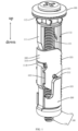
FIG. 1 is a structural diagram of an embodiment of the fastening assembly of the present disclosure; -
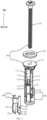
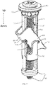
FIG. 2 is a partially exploded view of the fastening assembly shown inFIG. 1 ; -
FIG. 3 is a structural diagram of the mounting cylinder frame and the movable part shown inFIG. 2 ; -
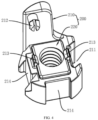
FIG. 4 is a structural diagram of the movable part shown inFIG. 2 ; -
FIG. 5 is a structural diagram of the fastening assembly shown inFIG. 1 when connecting two objects; -
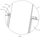
FIG. 6 is a partially enlarged view of part A shown inFIG. 5 ; -
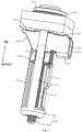
FIG. 7 is another structural diagram of the fastening assembly shown inFIG. 1 ; -
FIG. 8 is another structural diagram of the fastening assembly shown inFIG. 1 . - Reference mark:
-
Mounting cylinder frame 100,cylinder frame body 110, the firstvertical beam 111,bulge 111A,platform 111B,avoidance hole 111C, positioning block 111D,butting block 112, secondvertical beam 113,bolt 120,transmission rod 121; -
Movable part 200,movable part body 210, the firstsliding slot 211, connectingshaft 212,anti-falling block 213, the secondsliding slot 214, connectingblock 220; -
Turnover part 300, theconnecting arm 310, theturnover arm 320, theguide slot 321, thesnap notch 322, theanti-skid teeth 323; -
Gasket 400. - This part will describe the specific embodiment of the disclosure in detail. The preferred embodiment of the disclosure is shown in the attached drawings. The function of the attached drawings is to supplement the description of the text part of the description with graphics, so that people can intuitively and vividly understand each technical feature and the overall technical solution of the disclosure, but it cannot be understood as a limitation on the scope of the disclosure.
- In the description of the disclosure, if there is a description that the first, second, third, fourth, fifth, etc. are only used to distinguish the technical features, tit cannot be understood as indicating or implying the relative importance, or implicitly indicating the number of the indicated technical features, or implicitly indicating the order of the indicated technical features.
- In the description of the disclosure, it should be understood that the orientation or position relationship related to the orientation description, such as up, down, front, rear, left, right, etc., is based on the orientation or position relationship shown in the attached drawings, only for the convenience of describing the disclosure and simplifying the description, rather than indicating or implying that the device or element must have a specific orientation, or being constructed and operated in a specific orientation. Therefore, it cannot be understood as a limitation of the present disclosure.
- In the disclosure, unless otherwise clearly defined, "provide", "install", "connected" and other words shall be understood in a broad sense. For example, it may be directly connected or indirectly connected through an intermediate medium; it may be fixed connection, detachable connection or integrated forming; it may be mechanical connection; it may be the connection between two elements or the interaction between two elements. Those skilled in the art can reasonably determine the specific meaning of the above words in the disclosure in combination with the specific contents of the technical solution.
- Referring to
FIGS. 1 to 8 , an embodiment of the present disclosure relates to a fastening assembly, including amounting cylinder frame 100, amovable part 200 and aturnover part 300. - The
mounting cylinder frame 100 is provided with a firstvertical beam 111 and atransmission rod 121 which are arranged side by side. Themounting cylinder frame 100 is provided with abutting block 112 at the top of the firstvertical beam 111, thetransmission rod 121 passes through thebutting block 112, and the side wall of the firstvertical beam 111 is provided with abulge 111A. Themovable part 200 is connected with thetransmission rod 121. Theturnover part 300 is rotationally connected with themovable part 200. Theturnover part 300 is butted with thebulge 111A, theturnover part 300 is located between thebutting block 112 and themovable part 200, and theturnover part 300 has a vertical state and a horizontal state. Wherein thetransmission rod 121 can drive themovable part 200 to move along the axial direction of the firstvertical beam 111 to come close or move away from thebutting block 112, so as to drive theturnover part 300 to turnover under the force of thebulge 111A, so as to switch between the horizontal state or the vertical state. - In this embodiment, referring to
FIG. 1 andFIG. 2 , the top projection of theturnover part 300 is in a U shape. Theturnover part 300 includes a connectingarm 310 and twoopposite turnover arms 320. Both ends of the connectingarm 310 are respectively connected with the twoturnover arms 320. Both sides of the firstvertical beam 111 are provided withbulges 111A, and the twobulges 111A are butted with the inner walls of the twoturnover arms 320 one by one. Theturnover arm 320 is rotatably connected with themovable part 200, wherein the connectingarm 310 and the twoturnover arms 320 are an integrated structure. - Referring to
FIG. 1 ,FIG. 5 ,FIG. 7 andFIG. 8 , thetransmission rod 121 can drive themovable part 200 to move in the direction close to thebutting block 112. Themovable part 200 moving close to thebutting block 112 pushes the rotatingarm 320 to overturn, so that theturnover arm 320 switches to the horizontal state under the friction force of thebulge 111A. When theturnover arm 320 switches to the horizontal state, theturnover arm 320 butts with themovable part 200, theturnover arm 320 remains horizontal, and themovable part 200 can continue to push theturnover arm 320 in the horizontal state so that theturnover arm 320 continues to move in the direction close to thebutting block 112. - In addition, the
transmission rod 121 can drive themovable part 200 to move away from thebutting block 112, and themovable part 200 moving away from thebutting block 112 pulls theturnover arm 320 to move, so that theturnover arm 320 is turnover to the vertical state under the friction force of thebulge 111A. - It should be noted that the two
bulges 111A are butted with the inner walls of the twoturnover arms 320 one by one, which shows that theturnover part 300 is arranged on the firstvertical beam 111. - Through the above structure, when the fastening assembly passes through the mounting holes of the two objects, the
turnover part 300 can be switched from the vertical state to the horizontal state only through thetransmission rod 121. Theturnover part 300 in the horizontal state and the butting block 112 together clamp the two objects to complete the connection of the two objects. The above connection does not require the user to manually align the set nut. Therefore, it can reduce the labor intensity of users and optimize the user experience. - It can be understood that the above fastening assembly can also connect three, four or more objects.
- It can also be understood that, referring to
FIG. 5 , the horizontal length of theturnover part 300 in the horizontal state is greater than the aperture of the mounting hole. - In this embodiment, referring to
FIGS. 1 and5 , theturnover arm 320 is provided withanti-skid teeth 323. When theturnover arm 320 is in a horizontal state, theanti-skid teeth 323 are facing thebutting block 112. - Through the above structure, the
anti-skid teeth 323 and the butting block 112 together clamp the two objects, so as to increase the clamping effect of the two objects and optimize the connection stability of the two objects. - In this embodiment, referring to
FIG. 2 , the firstvertical beam 111 is provided with an avoidance section, the avoidance section is provided with anavoidance hole 111C, and the side wall of the avoidance section is provided with abulge 111A. - Through the above structure, the arrangement of the
avoidance hole 111C can make the twobulges 111A suitable for coping with the force when theturnover part 300 moves and overturn, so as to avoid the damage of the twobulges 111A due to too rigid. - In this embodiment, referring to
FIG. 3 , the firstvertical beam 111 is provided with a positioning block 111D. When theturnover part 300 is in the vertical state, the positioning block 111D butts against the top of themovable part 200. - Through the above structure, it can be determined that when the
turnover part 300 is in the vertical state, themovable part 200 is at the position of thetransmission rod 121. - The mounting
cylinder frame 100 includes acylinder frame body 100 and abolt 120. - Referring to
FIGS. 1 to 2 , thecylinder frame body 100 is provided with the firstvertical beam 111 and thebutting block 112, thebolt 120 is threaded through thecylinder frame body 110, the head of thebolt 120 is located above thebutting block 112, and the rod portion of thebolt 120 is thetransmission rod 121. - In some embodiments, the mounting
cylinder frame 100 includes acylinder frame body 100 and a push rod member, thecylinder frame body 100 is provided with the firstvertical beam 111 and thebutting block 112, the push rod member is arranged on the mountingcylinder frame 100, and the rod part of the push rod member is thetransmission rod 121. - In order to reduce the friction between the
bolt 120 and thecylinder frame body 110, referring toFIG. 1 andFIG. 2 , it also includes agasket 400. Thegasket 400 is sleeved on thetransmission rod 121, and thegasket 400 is located between the buttingblock 112 and the head of thebolt 120. - In order to improve the stability of the
turnover part 300 in the vertical state, referring toFIG. 2 , the firstvertical beam 111 is provided with aplatform 111B, and the connectingarm 310 of theturnover part 300 in the vertical state is butted with theplatform 111B. - The
movable part 200 includes amovable part body 210 and a connectingblock 220. - Referring to
FIGS. 2 and4 , themovable part body 210 is slidably connected with the firstvertical beam 111, themovable part body 210 is rotationally connected with theturnover arm 320, themovable part body 210 is provided with a mounting cavity, the connectingblock 220 is embedded in the mounting cavity, and the connectingblock 220 is sleeved on thetransmission rod 121 and threaded with thetransmission rod 121. The connectingblock 220 is provided with a polygonal nut, and the mounting cavity is matched with the connectingblock 220. - In this embodiment, the bottom of the mounting cavity is provided with an avoidance hole for the
transmission rod 121 to pass through. - The
movable part body 210 is slidably connected with the firstvertical beam 111. Specifically, referring toFIG. 2 ,FIG. 3 andFIG. 4 , themovable part body 210 is provided with a first slidingslot 211, and the firstvertical beam 111 is slidably arranged in the first slidingslot 211. - In order to increase the sliding stability of the
movable part body 210, referring toFIG. 2 ,FIG. 3 andFIG. 4 , thecylinder frame body 110 is further provided with a secondvertical beam 113, the secondvertical beam 113, the firstvertical beam 111 and thetransmission rod 121 are arranged side by side. Themovable part body 210 is provided with a second slidingslot 214 corresponding to the secondvertical beam 113, and the secondvertical beam 113 is slidably arranged in the second slidingslot 214. - In this embodiment, referring to
FIG. 1 andFIG. 5 , a limit space is formed between the firstvertical beam 111 and part of the secondvertical beam 113, wherein oneturnover arm 320 is located in the limit space. Through the above structure, it can prevent theturnover part 300 from disengaging when moving and flipping. - In this embodiment, the number of the second
vertical beam 113 and the second slidingslot 214 is set to two. - In some embodiments, the number of the second
vertical beam 113 and the second slidingslot 214 is set to three, four, etc. - The
movable part body 210 is rotationally connected with theturnover arm 320. Specifically, referring toFIGS. 3 to 4 , themovable part body 210 is provided with a connectingshaft 212, theturnover arm 320 is provided with aguide slot 321, and the connectingshaft 212 passes through theguide slot 321. - Through the above structure, during the movement and turnover of the
turnover part 300, the connectingshaft 212 slides in theguide slot 321 and rotates relative to theturnover arm 320. - In order to prevent the connecting
block 220 from falling out of the mounting cavity. Referring toFIG. 4 , themovable part body 210 is provided with ananti-falling block 213, wherein theanti-falling block 213 is butted against the connectingblock 220. - In this embodiment, referring to
FIG. 5 ,FIG. 6 andFIG. 8 , the connectingblock 220 partially extends out of the mounting cavity, and theturnover arm 320 is provided with asnap notch 322 matched with the extending portion of the connectingblock 220. When theturnover arm 320 is in a horizontal state, the extending portion of the connectingblock 220 is embedded in thesnap notch 322. - Through the above structure, the extending portion of the connecting
block 220 is embedded in thesnap notch 322 to increase the stability of butting between theturnover part 300 and themovable part 200, and can be further limited to the connectingblock 220 in the mounting cavity. - Of course, the present disclosure is not limited to the above embodiments. Those skilled in the art can also make equivalent modification or replacement without departing the spirit of the disclosure. These equivalent modification and replacement are included in the scope defined by the claims of the application.
Claims (10)
- A fastening assembly, comprising:a mounting cylinder frame (100), wherein the mounting cylinder frame is provided with a first vertical beam (111) and a transmission rod (121), the mounting cylinder frame (100) is provided with a butting block (112) at a top of the first vertical beam (111), the transmission rod (121) passes through the butting block (112), and a side wall of the first vertical beam (111) is provided with a bulge (111A);a movable part (200), wherein the movable part is connected with the transmission rod (121);a turnover part (300), wherein the turnover part is arranged on the first vertical beam (111) and the turnover part is rotatably connected with the movable part (200), the turnover part (300) is butted with the bulge (111A), the turnover part (300) is located between the butting block (112) and the movable part (200), and the turnover part has a vertical state and a horizontal state, wherein,the transmission rod (121) is configured to drive the movable part (200) to move along an axial direction of the first vertical beam (111), so as to drive the turnover part (300) to switch between the horizontal state or the vertical state under an action of the bulge (111A).
- The fastening assembly according to claim 1, wherein
the movable part (200) comprises:a movable part body (210), wherein the movable part body is slidably connected with the first vertical beam (111), the movable part body (210) is rotationally connected with the turnover part (300), and the movable part body (210) is provided with a mounting cavity;a connecting block (220), wherein the connecting block is embedded in the mounting cavity, and the connecting block (220) is sleeved on the transmission rod (121) and threaded with the transmission rod (121). - The fastening assembly according to claim 2, wherein
the movable part body (210) is provided with a connecting shaft (212), the turnover part (300) is provided with a guide slot (321), and the connecting shaft (212) passes through the guide slot (321). - The fastening assembly according to claim 2, wherein
the connecting block (220) partially extends out of the mounting cavity, and the turnover part (300) is provided with a snap notch (322) matched with an extending portion of the connecting block (220); and the extending portion of the connecting block (220) is embedded in the snap notch (322) when the turnover part (300) is in the horizontal state. - The fastening assembly according to claim 2, wherein
the movable part body (210) is provided with an anti-falling block (213), and the anti-falling block (213) is butted with the connecting block (220). - The fastening assembly according to claim 2, wherein
the mounting cylinder frame (100) is provided with a second vertical beam (113), the second vertical beam (113), the first vertical beam (111) and the transmission rod (121) are arranged side by side, and the second vertical beam (113) is slidably connected with the movable part body (210). - The fastening assembly according to claim 1, wherein
the first vertical beam (111) is provided with a platform (111B), and the turnover part (300) in the vertical state is butted with the platform (111B). - The fastening assembly according to claim 1, wherein
the first vertical beam (111) is provided with an avoidance hole (111C), and the avoidance hole (111C) is arranged to correspond to the bulge (111A). - The fastening assembly according to claim 1, wherein
the first vertical beam (111) is provided with a positioning block (111D), the positioning block (111D) butts against a top of the movable part (200) when the turnover part (300) is in the vertical state. - The fastening assembly according to claim 1, wherein
the turnover part (300) is provided with anti-skid teeth (323); and the anti-skid teeth (323) are facing the butting block (112) when the turnover part (300) is in the horizontal state.
Applications Claiming Priority (1)
| Application Number | Priority Date | Filing Date | Title |
|---|---|---|---|
| CN202121876730.XU CN216044797U (en) | 2021-08-11 | 2021-08-11 | Fastening assembly |
Publications (3)
| Publication Number | Publication Date |
|---|---|
| EP4134556A1 true EP4134556A1 (en) | 2023-02-15 |
| EP4134556C0 EP4134556C0 (en) | 2023-07-05 |
| EP4134556B1 EP4134556B1 (en) | 2023-07-05 |
Family
ID=80558129
Family Applications (1)
| Application Number | Title | Priority Date | Filing Date |
|---|---|---|---|
| EP22158234.9A Active EP4134556B1 (en) | 2021-08-11 | 2022-02-23 | Fastening assembly |
Country Status (4)
| Country | Link |
|---|---|
| US (1) | US20230047591A1 (en) |
| EP (1) | EP4134556B1 (en) |
| CN (1) | CN216044797U (en) |
| ES (1) | ES2952322T3 (en) |
Families Citing this family (1)
| Publication number | Priority date | Publication date | Assignee | Title |
|---|---|---|---|---|
| US20230056005A1 (en) * | 2021-08-18 | 2023-02-23 | Delta Cycle Corporation | Anchor assembly |
Citations (5)
| Publication number | Priority date | Publication date | Assignee | Title |
|---|---|---|---|---|
| FR1385043A (en) * | 1963-02-26 | 1965-01-08 | Fixing device | |
| US3532024A (en) * | 1968-12-26 | 1970-10-06 | Tool Works Inc | Toggle fastener |
| US4502826A (en) * | 1983-05-16 | 1985-03-05 | Centre De Recherche Industrielle Du Quebec | Toggle fastener |
| CA2592203A1 (en) * | 2006-06-21 | 2007-12-21 | John D. Davis | Pre-positionable toggle anchor system |
| US20090169331A1 (en) * | 2007-12-31 | 2009-07-02 | Jean Pilon | Wall anchor |
Family Cites Families (11)
| Publication number | Priority date | Publication date | Assignee | Title |
|---|---|---|---|---|
| US1386202A (en) * | 1918-07-24 | 1921-08-02 | U S Expansion Bolt Co | Attaching device |
| US2024871A (en) * | 1935-06-13 | 1935-12-17 | Edwin R Parsons | Toggle bolt and sleeve |
| US2950141A (en) * | 1957-05-28 | 1960-08-23 | Bell Telephone Labor Inc | Panel latch |
| US3127807A (en) * | 1961-10-13 | 1964-04-07 | Henry J Modrey | Hollow wall anchor with pivoted anchor member |
| DK105081C (en) * | 1964-02-24 | 1966-08-15 | Aackersberg Mortensen | Fastening means. |
| US4530630A (en) * | 1982-07-14 | 1985-07-23 | Brown Russell L | Expanding anchor fastener |
| JP4472167B2 (en) * | 2000-12-12 | 2010-06-02 | 若井産業株式会社 | Rotating nut |
| US6764261B1 (en) * | 2001-11-13 | 2004-07-20 | David Stadler | Locking device and method for catch basin and manhole covers, and the like |
| US6884012B2 (en) * | 2003-09-04 | 2005-04-26 | Illinois Tool Works Inc. | Heavy duty toggle bolt fastener assembly, and method of installing and removing the same |
| US11486432B2 (en) * | 2018-11-29 | 2022-11-01 | The Hillman Group, Inc. | Anchor assembly with toggle |
| EP4012198A1 (en) * | 2020-12-08 | 2022-06-15 | Xiamen Beewill Sanitary Co., Ltd. | Locking assembly |
-
2021
- 2021-08-11 CN CN202121876730.XU patent/CN216044797U/en active Active
-
2022
- 2022-02-23 EP EP22158234.9A patent/EP4134556B1/en active Active
- 2022-02-23 US US17/678,989 patent/US20230047591A1/en active Pending
- 2022-02-23 ES ES22158234T patent/ES2952322T3/en active Active
Patent Citations (5)
| Publication number | Priority date | Publication date | Assignee | Title |
|---|---|---|---|---|
| FR1385043A (en) * | 1963-02-26 | 1965-01-08 | Fixing device | |
| US3532024A (en) * | 1968-12-26 | 1970-10-06 | Tool Works Inc | Toggle fastener |
| US4502826A (en) * | 1983-05-16 | 1985-03-05 | Centre De Recherche Industrielle Du Quebec | Toggle fastener |
| CA2592203A1 (en) * | 2006-06-21 | 2007-12-21 | John D. Davis | Pre-positionable toggle anchor system |
| US20090169331A1 (en) * | 2007-12-31 | 2009-07-02 | Jean Pilon | Wall anchor |
Also Published As
| Publication number | Publication date |
|---|---|
| EP4134556C0 (en) | 2023-07-05 |
| CN216044797U (en) | 2022-03-15 |
| ES2952322T3 (en) | 2023-10-30 |
| US20230047591A1 (en) | 2023-02-16 |
| EP4134556B1 (en) | 2023-07-05 |
Similar Documents
| Publication | Publication Date | Title |
|---|---|---|
| EP4134556A1 (en) | Fastening assembly | |
| JP2018187347A (en) | Slide rail assembly | |
| TW200905098A (en) | Pivot structure of universal joint | |
| CN112498673B (en) | Actuating mechanism and unmanned aerial vehicle | |
| US10888993B2 (en) | Assembly for driving waist of robot and robot having the same | |
| US5762303A (en) | Tilting angle adjusting device for use in a projector | |
| CN218498610U (en) | Automatically controlled cabinet of combination convenient to dismantle maintenance | |
| CN215494842U (en) | Novel computer case | |
| JP2002194784A (en) | Slide type shower hook attaching device | |
| US20210031275A1 (en) | Rotating element operating device | |
| CN103388729A (en) | Easy-to-assemble-and-disassemble screen supporting structure | |
| WO2014061720A1 (en) | Furniture with table top flap | |
| US20200232555A1 (en) | Gear shifting device for electric cars | |
| JP2947088B2 (en) | Injection molding machine | |
| CN205560151U (en) | Module handle and display screen module | |
| US11808255B2 (en) | Floor pump | |
| CN216374084U (en) | Portable tire dismounting device | |
| CN216305672U (en) | Locking device | |
| CN212658509U (en) | Sampling gun with freely detachable gun head | |
| JP2001106128A (en) | Lower traveling element for construction machine | |
| CN208335510U (en) | A kind of Internet of Things practical traning platform | |
| CN212129113U (en) | Plastic drainage plate rewinding device | |
| WO2019205880A1 (en) | Execution mechanism for adjusting display terminal, display terminal assembly and vehicle | |
| KR200172451Y1 (en) | Apparatus for mounting an accessory device of display monitor | |
| KR100205553B1 (en) | Connection means of cabinet for television |
Legal Events
| Date | Code | Title | Description |
|---|---|---|---|
| PUAI | Public reference made under article 153(3) epc to a published international application that has entered the european phase |
Free format text: ORIGINAL CODE: 0009012 |
|
| STAA | Information on the status of an ep patent application or granted ep patent |
Free format text: STATUS: REQUEST FOR EXAMINATION WAS MADE |
|
| 17P | Request for examination filed |
Effective date: 20220223 |
|
| AK | Designated contracting states |
Kind code of ref document: A1 Designated state(s): AL AT BE BG CH CY CZ DE DK EE ES FI FR GB GR HR HU IE IS IT LI LT LU LV MC MK MT NL NO PL PT RO RS SE SI SK SM TR |
|
| GRAP | Despatch of communication of intention to grant a patent |
Free format text: ORIGINAL CODE: EPIDOSNIGR1 |
|
| STAA | Information on the status of an ep patent application or granted ep patent |
Free format text: STATUS: GRANT OF PATENT IS INTENDED |
|
| INTG | Intention to grant announced |
Effective date: 20230310 |
|
| GRAS | Grant fee paid |
Free format text: ORIGINAL CODE: EPIDOSNIGR3 |
|
| GRAA | (expected) grant |
Free format text: ORIGINAL CODE: 0009210 |
|
| STAA | Information on the status of an ep patent application or granted ep patent |
Free format text: STATUS: THE PATENT HAS BEEN GRANTED |
|
| AK | Designated contracting states |
Kind code of ref document: B1 Designated state(s): AL AT BE BG CH CY CZ DE DK EE ES FI FR GB GR HR HU IE IS IT LI LT LU LV MC MK MT NL NO PL PT RO RS SE SI SK SM TR |
|
| REG | Reference to a national code |
Ref country code: CH Ref legal event code: EP |
|
| REG | Reference to a national code |
Ref country code: AT Ref legal event code: REF Ref document number: 1585096 Country of ref document: AT Kind code of ref document: T Effective date: 20230715 |
|
| REG | Reference to a national code |
Ref country code: DE Ref legal event code: R096 Ref document number: 602022000166 Country of ref document: DE |
|
| REG | Reference to a national code |
Ref country code: IE Ref legal event code: FG4D |
|
| U01 | Request for unitary effect filed |
Effective date: 20230717 |
|
| U07 | Unitary effect registered |
Designated state(s): AT BE BG DE DK EE FI FR IT LT LU LV MT NL PT SE SI Effective date: 20230725 |
|
| REG | Reference to a national code |
Ref country code: LT Ref legal event code: MG9D |
|
| REG | Reference to a national code |
Ref country code: ES Ref legal event code: FG2A Ref document number: 2952322 Country of ref document: ES Kind code of ref document: T3 Effective date: 20231030 |
|
| PG25 | Lapsed in a contracting state [announced via postgrant information from national office to epo] |
Ref country code: GR Free format text: LAPSE BECAUSE OF FAILURE TO SUBMIT A TRANSLATION OF THE DESCRIPTION OR TO PAY THE FEE WITHIN THE PRESCRIBED TIME-LIMIT Effective date: 20231006 |
|
| PG25 | Lapsed in a contracting state [announced via postgrant information from national office to epo] |
Ref country code: IS Free format text: LAPSE BECAUSE OF FAILURE TO SUBMIT A TRANSLATION OF THE DESCRIPTION OR TO PAY THE FEE WITHIN THE PRESCRIBED TIME-LIMIT Effective date: 20231105 |
|
| PG25 | Lapsed in a contracting state [announced via postgrant information from national office to epo] |
Ref country code: RS Free format text: LAPSE BECAUSE OF FAILURE TO SUBMIT A TRANSLATION OF THE DESCRIPTION OR TO PAY THE FEE WITHIN THE PRESCRIBED TIME-LIMIT Effective date: 20230705 Ref country code: NO Free format text: LAPSE BECAUSE OF FAILURE TO SUBMIT A TRANSLATION OF THE DESCRIPTION OR TO PAY THE FEE WITHIN THE PRESCRIBED TIME-LIMIT Effective date: 20231005 Ref country code: IS Free format text: LAPSE BECAUSE OF FAILURE TO SUBMIT A TRANSLATION OF THE DESCRIPTION OR TO PAY THE FEE WITHIN THE PRESCRIBED TIME-LIMIT Effective date: 20231105 Ref country code: HR Free format text: LAPSE BECAUSE OF FAILURE TO SUBMIT A TRANSLATION OF THE DESCRIPTION OR TO PAY THE FEE WITHIN THE PRESCRIBED TIME-LIMIT Effective date: 20230705 Ref country code: GR Free format text: LAPSE BECAUSE OF FAILURE TO SUBMIT A TRANSLATION OF THE DESCRIPTION OR TO PAY THE FEE WITHIN THE PRESCRIBED TIME-LIMIT Effective date: 20231006 |
|
| U20 | Renewal fee paid [unitary effect] |
Year of fee payment: 3 Effective date: 20240108 |
|
| PG25 | Lapsed in a contracting state [announced via postgrant information from national office to epo] |
Ref country code: PL Free format text: LAPSE BECAUSE OF FAILURE TO SUBMIT A TRANSLATION OF THE DESCRIPTION OR TO PAY THE FEE WITHIN THE PRESCRIBED TIME-LIMIT Effective date: 20230705 |
|
| PGFP | Annual fee paid to national office [announced via postgrant information from national office to epo] |
Ref country code: ES Payment date: 20240307 Year of fee payment: 3 |
|
| PG25 | Lapsed in a contracting state [announced via postgrant information from national office to epo] |
Ref country code: SM Free format text: LAPSE BECAUSE OF FAILURE TO SUBMIT A TRANSLATION OF THE DESCRIPTION OR TO PAY THE FEE WITHIN THE PRESCRIBED TIME-LIMIT Effective date: 20230705 Ref country code: RO Free format text: LAPSE BECAUSE OF FAILURE TO SUBMIT A TRANSLATION OF THE DESCRIPTION OR TO PAY THE FEE WITHIN THE PRESCRIBED TIME-LIMIT Effective date: 20230705 Ref country code: CZ Free format text: LAPSE BECAUSE OF FAILURE TO SUBMIT A TRANSLATION OF THE DESCRIPTION OR TO PAY THE FEE WITHIN THE PRESCRIBED TIME-LIMIT Effective date: 20230705 Ref country code: SK Free format text: LAPSE BECAUSE OF FAILURE TO SUBMIT A TRANSLATION OF THE DESCRIPTION OR TO PAY THE FEE WITHIN THE PRESCRIBED TIME-LIMIT Effective date: 20230705 |