EP4134533A1 - Mechanische antriebswellenanordnungen für heckkegelgeneratoren - Google Patents
Mechanische antriebswellenanordnungen für heckkegelgeneratoren Download PDFInfo
- Publication number
- EP4134533A1 EP4134533A1 EP22190388.3A EP22190388A EP4134533A1 EP 4134533 A1 EP4134533 A1 EP 4134533A1 EP 22190388 A EP22190388 A EP 22190388A EP 4134533 A1 EP4134533 A1 EP 4134533A1
- Authority
- EP
- European Patent Office
- Prior art keywords
- shaft
- generator
- thru
- coupling
- coupler mount
- Prior art date
- Legal status (The legal status is an assumption and is not a legal conclusion. Google has not performed a legal analysis and makes no representation as to the accuracy of the status listed.)
- Granted
Links
Images


Classifications
-
- F—MECHANICAL ENGINEERING; LIGHTING; HEATING; WEAPONS; BLASTING
- F01—MACHINES OR ENGINES IN GENERAL; ENGINE PLANTS IN GENERAL; STEAM ENGINES
- F01D—NON-POSITIVE DISPLACEMENT MACHINES OR ENGINES, e.g. STEAM TURBINES
- F01D5/00—Blades; Blade-carrying members; Heating, heat-insulating, cooling or antivibration means on the blades or the members
- F01D5/02—Blade-carrying members, e.g. rotors
- F01D5/026—Shaft to shaft connections
-
- B—PERFORMING OPERATIONS; TRANSPORTING
- B64—AIRCRAFT; AVIATION; COSMONAUTICS
- B64D—EQUIPMENT FOR FITTING IN OR TO AIRCRAFT; FLIGHT SUITS; PARACHUTES; ARRANGEMENT OR MOUNTING OF POWER PLANTS OR PROPULSION TRANSMISSIONS IN AIRCRAFT
- B64D41/00—Power installations for auxiliary purposes
-
- B—PERFORMING OPERATIONS; TRANSPORTING
- B64—AIRCRAFT; AVIATION; COSMONAUTICS
- B64D—EQUIPMENT FOR FITTING IN OR TO AIRCRAFT; FLIGHT SUITS; PARACHUTES; ARRANGEMENT OR MOUNTING OF POWER PLANTS OR PROPULSION TRANSMISSIONS IN AIRCRAFT
- B64D35/00—Transmitting power from power plants to propellers or rotors; Arrangements of transmissions
-
- F—MECHANICAL ENGINEERING; LIGHTING; HEATING; WEAPONS; BLASTING
- F01—MACHINES OR ENGINES IN GENERAL; ENGINE PLANTS IN GENERAL; STEAM ENGINES
- F01D—NON-POSITIVE DISPLACEMENT MACHINES OR ENGINES, e.g. STEAM TURBINES
- F01D15/00—Adaptations of machines or engines for special use; Combinations of engines with devices driven thereby
- F01D15/10—Adaptations for driving, or combinations with, electric generators
-
- F—MECHANICAL ENGINEERING; LIGHTING; HEATING; WEAPONS; BLASTING
- F02—COMBUSTION ENGINES; HOT-GAS OR COMBUSTION-PRODUCT ENGINE PLANTS
- F02C—GAS-TURBINE PLANTS; AIR INTAKES FOR JET-PROPULSION PLANTS; CONTROLLING FUEL SUPPLY IN AIR-BREATHING JET-PROPULSION PLANTS
- F02C7/00—Features, components parts, details or accessories, not provided for in, or of interest apart form groups F02C1/00 - F02C6/00; Air intakes for jet-propulsion plants
- F02C7/36—Power transmission arrangements between the different shafts of the gas turbine plant, or between the gas-turbine plant and the power user
-
- F—MECHANICAL ENGINEERING; LIGHTING; HEATING; WEAPONS; BLASTING
- F02—COMBUSTION ENGINES; HOT-GAS OR COMBUSTION-PRODUCT ENGINE PLANTS
- F02C—GAS-TURBINE PLANTS; AIR INTAKES FOR JET-PROPULSION PLANTS; CONTROLLING FUEL SUPPLY IN AIR-BREATHING JET-PROPULSION PLANTS
- F02C7/00—Features, components parts, details or accessories, not provided for in, or of interest apart form groups F02C1/00 - F02C6/00; Air intakes for jet-propulsion plants
- F02C7/32—Arrangement, mounting, or driving, of auxiliaries
-
- F—MECHANICAL ENGINEERING; LIGHTING; HEATING; WEAPONS; BLASTING
- F05—INDEXING SCHEMES RELATING TO ENGINES OR PUMPS IN VARIOUS SUBCLASSES OF CLASSES F01-F04
- F05D—INDEXING SCHEME FOR ASPECTS RELATING TO NON-POSITIVE-DISPLACEMENT MACHINES OR ENGINES, GAS-TURBINES OR JET-PROPULSION PLANTS
- F05D2220/00—Application
- F05D2220/30—Application in turbines
- F05D2220/32—Application in turbines in gas turbines
- F05D2220/323—Application in turbines in gas turbines for aircraft propulsion, e.g. jet engines
-
- F—MECHANICAL ENGINEERING; LIGHTING; HEATING; WEAPONS; BLASTING
- F05—INDEXING SCHEMES RELATING TO ENGINES OR PUMPS IN VARIOUS SUBCLASSES OF CLASSES F01-F04
- F05D—INDEXING SCHEME FOR ASPECTS RELATING TO NON-POSITIVE-DISPLACEMENT MACHINES OR ENGINES, GAS-TURBINES OR JET-PROPULSION PLANTS
- F05D2220/00—Application
- F05D2220/70—Application in combination with
- F05D2220/76—Application in combination with an electrical generator
-
- F—MECHANICAL ENGINEERING; LIGHTING; HEATING; WEAPONS; BLASTING
- F05—INDEXING SCHEMES RELATING TO ENGINES OR PUMPS IN VARIOUS SUBCLASSES OF CLASSES F01-F04
- F05D—INDEXING SCHEME FOR ASPECTS RELATING TO NON-POSITIVE-DISPLACEMENT MACHINES OR ENGINES, GAS-TURBINES OR JET-PROPULSION PLANTS
- F05D2240/00—Components
- F05D2240/60—Shafts
-
- F—MECHANICAL ENGINEERING; LIGHTING; HEATING; WEAPONS; BLASTING
- F05—INDEXING SCHEMES RELATING TO ENGINES OR PUMPS IN VARIOUS SUBCLASSES OF CLASSES F01-F04
- F05D—INDEXING SCHEME FOR ASPECTS RELATING TO NON-POSITIVE-DISPLACEMENT MACHINES OR ENGINES, GAS-TURBINES OR JET-PROPULSION PLANTS
- F05D2240/00—Components
- F05D2240/60—Shafts
- F05D2240/61—Hollow
-
- F—MECHANICAL ENGINEERING; LIGHTING; HEATING; WEAPONS; BLASTING
- F05—INDEXING SCHEMES RELATING TO ENGINES OR PUMPS IN VARIOUS SUBCLASSES OF CLASSES F01-F04
- F05D—INDEXING SCHEME FOR ASPECTS RELATING TO NON-POSITIVE-DISPLACEMENT MACHINES OR ENGINES, GAS-TURBINES OR JET-PROPULSION PLANTS
- F05D2250/00—Geometry
- F05D2250/10—Two-dimensional
- F05D2250/11—Two-dimensional triangular
-
- F—MECHANICAL ENGINEERING; LIGHTING; HEATING; WEAPONS; BLASTING
- F05—INDEXING SCHEMES RELATING TO ENGINES OR PUMPS IN VARIOUS SUBCLASSES OF CLASSES F01-F04
- F05D—INDEXING SCHEME FOR ASPECTS RELATING TO NON-POSITIVE-DISPLACEMENT MACHINES OR ENGINES, GAS-TURBINES OR JET-PROPULSION PLANTS
- F05D2250/00—Geometry
- F05D2250/10—Two-dimensional
- F05D2250/13—Two-dimensional trapezoidal
- F05D2250/132—Two-dimensional trapezoidal hexagonal
-
- F—MECHANICAL ENGINEERING; LIGHTING; HEATING; WEAPONS; BLASTING
- F05—INDEXING SCHEMES RELATING TO ENGINES OR PUMPS IN VARIOUS SUBCLASSES OF CLASSES F01-F04
- F05D—INDEXING SCHEME FOR ASPECTS RELATING TO NON-POSITIVE-DISPLACEMENT MACHINES OR ENGINES, GAS-TURBINES OR JET-PROPULSION PLANTS
- F05D2260/00—Function
- F05D2260/30—Retaining components in desired mutual position
- F05D2260/31—Retaining bolts or nuts
-
- F—MECHANICAL ENGINEERING; LIGHTING; HEATING; WEAPONS; BLASTING
- F05—INDEXING SCHEMES RELATING TO ENGINES OR PUMPS IN VARIOUS SUBCLASSES OF CLASSES F01-F04
- F05D—INDEXING SCHEME FOR ASPECTS RELATING TO NON-POSITIVE-DISPLACEMENT MACHINES OR ENGINES, GAS-TURBINES OR JET-PROPULSION PLANTS
- F05D2260/00—Function
- F05D2260/40—Transmission of power
Definitions
- This disclosure is generally directed to drive shafts.
- an aircraft drive shaft system includes a generator shaft extending along a longitudinal axis with a longitudinal bore defined through the generator shaft, and a thru shaft extending through the longitudinal bore of the generator shaft.
- the thru shaft includes a front coupler mount at a first end of the thru shaft operative to receive torque input and a rear coupler mount at a second end of the thru shaft opposite the first end.
- the generator shaft includes a rear coupler mount at a second end of the generator shaft that is coupled to the rear coupler mount of the thru shaft operative to transmit torque from the front coupler mount of the thru shaft, through the thru shaft, and into the generator shaft.
- the system includes a coupling, where the rear coupler mount is indirectly operatively connected the generator shaft via the coupling.
- the rear coupler mount of the thru shaft is fastened directly to the coupling
- the rear coupler mount of the generator shaft is fastened directly to the coupling.
- each of the front coupler mount and the rear coupler mount of each of the thru shaft and the generator shaft have n vertices, wherein each vertex includes a bore operative to receive a fastener.
- the coupling includes 2n vertices corresponding to each vertex of each respective coupler mount.
- Each vertex of the coupling includes a bore operative to receive a fastener, such that the fastener extends through each respective bore of the coupling and corresponding coupler mount to fasten the respective coupler mount of the respective shaft to the coupling.
- the aircraft drive system includes a shaft drive having a front coupler mount at a second end of the shaft drive operative to fasten to the front coupler mount of the thru shaft operative to transmit torque from the shaft drive to the generator shaft through the thru shaft.
- a front coupling is included, where the front coupler mount of the shaft drive is fastened directly to the front coupling, and wherein the front coupler mount of the thru shaft is directly fastened to the front coupling.
- the shaft drive includes a splined section.
- a rotor is operatively connected to the generator shaft to rotate within a generator housing to generate electrical energy.
- an aircraft system comprising a gas turbine engine having a compressor section, a turbine section, and a spool shaft operatively connecting the compressor section to be driven by the turbine section.
- the drive shaft system includes a generator shaft extending along a longitudinal axis with a longitudinal bore defined through the generator shaft, and a thru shaft extending through the longitudinal bore of the generator shaft.
- the thru shaft includes a front coupler mount at a first end of the thru shaft operative to receive torque input and a rear coupler mount at a second end of the thru shaft opposite the first end.
- the generator shaft includes a rear coupler mount at a second end of the generator shaft that is coupled to the rear coupler mount of the thru shaft operative to transmit torque from the front coupler mount of the thru shaft, through the thru shaft, and into the generator shaft.
- the thru shaft is operatively connected to the spool shaft.
- a rotor is operatively connected to the generator shaft to rotate within a generator housing to generate electrical energy and a stator is operatively connected to the generator housing radially outward of the rotor.
- a tail cone is included at an outlet of the turbine section, where the rotor and stator are mounted in the tail cone.
- the gas turbine engine can be selected from the group consisting of a turbojet, a turbofan, a turboprop, or a turboshaft.
- the aircraft system further includes a coupling, where the rear coupler mount is indirectly operatively connected the generator shaft via the coupling.
- the rear coupler mount of the thru shaft is fastened directly to the coupling
- the rear coupler mount of the generator shaft is fastened directly to the coupling.
- each of the front coupler mount and the rear coupler mount of each of the thru shaft and the generator shaft have n vertices, each vertex having a bore operative to receive a fastener.
- the coupling includes 2n vertices corresponding to each vertex of each respective coupler mount.
- Each vertex of the coupling includes a bore operative to receive a fastener, such that the fastener extends through each respective bore of the coupling and corresponding coupler mount to fasten the respective coupler mount of the respective shaft to the coupling.
- the spool shaft includes a front coupler mount at a second end of the spool shaft operative to fasten to the front coupler mount of the thru shaft operative to transmit torque from the spool shaft to the generator shaft through the thru shaft.
- the aircraft system further includes a front coupling, where the front coupler mount of the spool shaft is fastened directly to the front coupling, and the front coupler mount of the thru shaft is directly fastened to the front coupling.
- an aircraft generator system includes a generator housing, a stator operatively connected to the generator housing, a generator shaft extending along a longitudinal axis of the generator housing, the generator shaft having a longitudinal bore therethrough, a rotor operatively connected to the generator shaft, and a thru shaft extending through the longitudinal bore of the generator shaft.
- the thru shaft is operatively connected to a spool shaft of a gas turbine engine on a first end, and the thru shaft is operatively connected to the generator shaft on a second end such that the generator is driven by the spool shaft through the thru shaft.
- the generator system is integrally mounted in a tail cone of the gas turbine engine.
- the spool shaft is a low pressure turbine shaft of a dual spool gas turbine engine.
- the aircraft generator system includes a front coupling and a rear coupling, the first end of the thru shaft being indirectly operatively connected to the spool shaft via the front coupling, and the second end of the thru shaft being indirectly operatively connected to the generator shaft via the rear coupling.
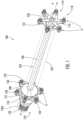
- FIG. 1 an illustrative view of an embodiment of a system in accordance with the disclosure is shown in Fig. 1 and is designated generally by reference character 100.
- FIGs. 2-3 Other embodiments and/or aspects of this disclosure are shown in Figs. 2-3 .
- Embodiments of the systems and methods provided herein can provide improved accommodation of misalignment of generator shafts for ease of installation and operation.
- a generator can coupled to the engine to be driven by a spool shaft of the engine. Deflections between the fan shaft and generator shaft may arise due to tolerances and thermal defections which can result in excessive seal wear and coupler failure.
- One solution is to use a plastic coupler to isolate and allow angular mismatch between the shafts as well as axial deflections, but this can result in shaft shear based on deflection.
- the systems and methods provided herein provide improvements to drive systems for aircraft engine generators.
- the drive shaft system 100 includes a generator shaft 102 extending along a longitudinal axis A with a longitudinal bore 104 defined through the generator shaft 102.
- a thru shaft 106 extends through the longitudinal bore 104 of the generator shaft 102.
- the thru shaft 106 includes, a front coupler mount 108 at a first end 110 operative to receive torque input, and a rear coupler mount 112 at a second end 114 opposite the first end 108.
- the generator shaft 102 includes a rear coupler mount 116 at a second end 118 of the generator shaft configured to be coupled to the rear coupler mount 112 of the thru shaft 106 to transmit torque from the front coupler mount 108 of the thru shaft 106, through the thru shaft 16, and into the generator shaft 102.
- a shaft drive 120 is operatively coupled to the thru shaft 106 on the first end 110 of the thru shaft 106 via a front coupler mount 122 at a second end 124 of the shaft drive 120 to transmit torque from the shaft drive 120 to the generator shaft 102 through the thru shaft 106.
- the shaft drive 120 can be any suitable shaft drive, for example, the shaft drive 120 can be splined or include at least a splined section 120a.
- a front end coupling 126 operatively connects the front coupler mount 122 of the shaft drive 120 to the front coupler mount 108 of the thru shaft 106.
- a rear end coupling 128 operatively connects the rear coupler mount 112 of the thru shaft 106 to the rear coupler mount 116 of the generator shaft 102.
- Each of the front coupler mounts 108, 122 and the rear coupler mounts 112, 116 are fastened directly to the respective coupling 126, 128 such that there is no direct connection between the shaft drive 120 and the thru shaft 106 or between the thru shaft 106 and the generator shaft 102.
- each of the front coupler mounts 108, 122 and the rear coupler mounts 112, 116 can have n vertices (labeled V in Fig. 1 ), wherein each vertex V includes a bore 130 operative to receive a fastener 132.
- each coupling 126, 128 thus can include 2n vertices corresponding to each vertex V of each respective coupler mount 108, 122, 112, 116 (e.g.
- each coupling 126, 128 therefore includes six vertices).
- Each vertex of the couplings 126, 128 also includes a corresponding bore 130 operative to receive the fastener 132 to mount the respective coupler mounts 108, 122, 112, 116 to the respective coupling 126, 128.
- the fastener 132 extends through each respective bore 130 of the coupling 126, 128 and corresponding coupler mount 108, 122, 112, 116 to fasten the respective coupler mount 108, 122, 112, 116 of the respective shaft 102, 106, 120 to the couplings 126, 128.
- the drive system 100 as presented herein can be included in an aircraft 234 implementing the aircraft system 200.
- the aircraft 234 can include an engine 236, where the engine 236 can be a propulsive energy engine (e.g. creating thrust for the aircraft 234), or a non-propulsive energy engine.
- the engine 236 is a turbofan engine, although the present disclosure may likewise be used with other engine types, for example turbojet, turboprop, or turboshaft.
- the gas turbine engine 236 includes a compressor section 238, a turbine section 240, and a spool shaft 220 operatively connecting the compressor section 238 to be driven by the turbine section 240 and the drive shaft system 100.
- the shaft drive 120 is the spool shaft 220 of the gas turbine engine 236, such that the thru shaft 106 is operatively connected to the spool shaft 220 in any suitable manner as described herein (e.g. via coupler mounts 108, 122).
- the spool shaft 220 can be a low pressure turbine shaft of a dual spool gas turbine engine.
- a rotor 242 is operatively connected to the generator shaft 102 to rotate within a generator housing 244 to generate electrical energy
- a stator 246 is operatively connected to the generator housing 244 radially outward of the rotor 242.
- a tail cone 248 is included at an outlet 250 of the turbine section 240, where the generator housing 244 and elements included therein (e.g. generator shaft 106, rotor 242, and stator 246) are mounted in the tail cone 248.
- a generator system 300 for example for use in an aircraft engine 236.
- the description of common elements with respect to the drive system 100 and aircraft system 200 that have been described above are not repeated.
- the drive system 100 as shown and described herein can be included in the aircraft generator system 300 (e.g. as a tail cone generator).
- the thru shaft 106 is operatively connected to the spool shaft 220 of a gas turbine engine 236 on a first end 110, and the thru shaft 106 is operatively connected to the generator shaft 104 on a second end 114, so that the generator shaft 102 is driven by the spool shaft 220 through the thru shaft 106.
- the rotor 242 and stator 246 are omitted from Fig. 3 .
- a generator end cap 352 can be fastened to the generator housing 244 for covering the rear end coupling 128 during operation.
- a method of assembling the generator system 300 into an aircraft engine includes mounting the front coupling 126 to the spool shaft 220 (e.g. via front coupler mount 122), mounting the first end 110 of the thru shaft 106 to the front coupling 126 (e.g. via front coupler mount 108), and assembling the generator housing 244 around the thru shaft 106 and spool shaft 220.
- the method can next include mounting the rear coupling 128 to the second end 114 of the thru shaft 106 (e.g. via rear coupler mount 112), mounting the rear coupling 128 to the second end 118 of the generator shaft 102 (e.g. via rear coupler mount 116), and mounting the rear cover 352 to the generator housing 244.
- Assembly of the generator system 300 to the engine 236 in such a manner allows for improved assembly over previous systems and methods in that there is no blind assembly of a long shaft into its mating feature, for example how a typical low pressure spool shaft may be done. Without blind assembly, assembly can be made easier, assembly mistakes can be avoided, as well as damage to parts during assembly may be prevented.
- the pivot point of the thru shaft can be moved away from the spool shaft coupler (e.g. front end coupling).
- the spool shaft coupler e.g. front end coupling
- Increasing the distance between the spool shaft coupler and the thru shaft pivot point can therefore reduce the influence of shaft offset and thermal deflections on the angularity between the two shafts and the amount of misalignment the coupler has to compensate for.
- the front and rear end couplings can also compensate for any axial movement due to thermal influence.
- Embodiments can be advantageous over typical generator shafts by reducing the risk of spool shaft/generator dynamic instability, which in some instances may impact engine vibrations level and/or durability degradation of engine seals/coupling and/or the generator over time.
- the thru shaft can also allow the generator to be moved forward (e.g. closer to the turbine section in a tail cone generator) which can reduce the overhung mass and subsequently the loading on the engine mounts and overall engine structure.
- any numerical values disclosed herein can be exact values or can be values within a range. Further, any terms of approximation (e.g., “about”, “approximately”, “around”) used in this disclosure can mean the stated value within a range. For example, in certain embodiments, the range can be within (plus or minus) 20%, or within 10%, or within 5%, or within 2%, or within any other suitable percentage or number as appreciated by those having ordinary skill in the art (e.g., for known tolerance limits or error ranges).
- a reference to "A and/or B", when used in conjunction with open-ended language such as “comprising” can refer, in one embodiment, to A only (optionally including elements other than B); in another embodiment, to B only (optionally including elements other than A); in yet another embodiment, to both A and B (optionally including other elements); etc.
Landscapes
- Engineering & Computer Science (AREA)
- Mechanical Engineering (AREA)
- General Engineering & Computer Science (AREA)
- Chemical & Material Sciences (AREA)
- Combustion & Propulsion (AREA)
- Aviation & Aerospace Engineering (AREA)
- Connection Of Motors, Electrical Generators, Mechanical Devices, And The Like (AREA)
Applications Claiming Priority (1)
| Application Number | Priority Date | Filing Date | Title |
|---|---|---|---|
| US17/402,503 US11719101B2 (en) | 2021-08-14 | 2021-08-14 | Mechanical drive shaft arrangements for tail cone generators |
Publications (2)
| Publication Number | Publication Date |
|---|---|
| EP4134533A1 true EP4134533A1 (de) | 2023-02-15 |
| EP4134533B1 EP4134533B1 (de) | 2025-05-21 |
Family
ID=82939697
Family Applications (1)
| Application Number | Title | Priority Date | Filing Date |
|---|---|---|---|
| EP22190388.3A Active EP4134533B1 (de) | 2021-08-14 | 2022-08-15 | Mechanische antriebswellenanordnungen für heckkegelgeneratoren |
Country Status (4)
| Country | Link |
|---|---|
| US (1) | US11719101B2 (de) |
| EP (1) | EP4134533B1 (de) |
| BR (1) | BR102022016050A2 (de) |
| CA (1) | CA3170495A1 (de) |
Families Citing this family (3)
| Publication number | Priority date | Publication date | Assignee | Title |
|---|---|---|---|---|
| EP4414268A1 (de) * | 2023-02-13 | 2024-08-14 | Hamilton Sundstrand Corporation | Stromversorgungssystem |
| EP4723963A1 (de) | 2023-05-05 | 2026-04-15 | Dendro Technologies, Inc. | Bestimmung der temperatur von ausgeatmeter luft |
| US12140152B1 (en) * | 2023-08-30 | 2024-11-12 | Rtx Corporation | Nose cone/spinner power takeoff |
Citations (3)
| Publication number | Priority date | Publication date | Assignee | Title |
|---|---|---|---|---|
| US20100156113A1 (en) * | 2008-12-22 | 2010-06-24 | Hamilton Sundstrand Corporation | Generator coupling for use with gas turbine engine |
| US20130014513A1 (en) * | 2011-07-15 | 2013-01-17 | Barry Barnett | Connection for generator in a gas turbine engine |
| US20210119511A1 (en) * | 2018-03-29 | 2021-04-22 | Safran Electrical & Power | Generator having a disconnect mechanism |
Family Cites Families (4)
| Publication number | Priority date | Publication date | Assignee | Title |
|---|---|---|---|---|
| JP6511265B2 (ja) | 2014-12-24 | 2019-05-15 | 川崎重工業株式会社 | 航空機用エンジン装置 |
| US10883424B2 (en) | 2016-07-19 | 2021-01-05 | Pratt & Whitney Canada Corp. | Multi-spool gas turbine engine architecture |
| US11319895B2 (en) | 2019-03-15 | 2022-05-03 | Hamilton Sundstrand Corporation | Integrated tail cone and mounted generator |
| US11661856B2 (en) * | 2021-03-19 | 2023-05-30 | Rolls-Royce North American Technologies Inc. | Gas turbine engine with embedded generator |
-
2021
- 2021-08-14 US US17/402,503 patent/US11719101B2/en active Active
-
2022
- 2022-08-12 CA CA3170495A patent/CA3170495A1/en active Pending
- 2022-08-12 BR BR102022016050-3A patent/BR102022016050A2/pt unknown
- 2022-08-15 EP EP22190388.3A patent/EP4134533B1/de active Active
Patent Citations (3)
| Publication number | Priority date | Publication date | Assignee | Title |
|---|---|---|---|---|
| US20100156113A1 (en) * | 2008-12-22 | 2010-06-24 | Hamilton Sundstrand Corporation | Generator coupling for use with gas turbine engine |
| US20130014513A1 (en) * | 2011-07-15 | 2013-01-17 | Barry Barnett | Connection for generator in a gas turbine engine |
| US20210119511A1 (en) * | 2018-03-29 | 2021-04-22 | Safran Electrical & Power | Generator having a disconnect mechanism |
Also Published As
| Publication number | Publication date |
|---|---|
| BR102022016050A2 (pt) | 2024-01-02 |
| CA3170495A1 (en) | 2023-02-14 |
| US20230052410A1 (en) | 2023-02-16 |
| US11719101B2 (en) | 2023-08-08 |
| EP4134533B1 (de) | 2025-05-21 |
Similar Documents
| Publication | Publication Date | Title |
|---|---|---|
| EP4134533A1 (de) | Mechanische antriebswellenanordnungen für heckkegelgeneratoren | |
| US11181046B1 (en) | High speed shaft flexible coupling | |
| EP3361073A1 (de) | Mehrwellen-gasturbinentriebwerk | |
| EP2597269B1 (de) | Träger für eine elektrische Maschine in einem Turbinenmotor | |
| EP3361057A2 (de) | Turbinenrotor mit geringen überdrehzahlanforderungen | |
| US8376700B2 (en) | Compressed air starter for turbomachine | |
| EP3321488A1 (de) | Zubehöranordnung für gasturbinenmotor | |
| US11085377B2 (en) | Shaft break device for an electricity generator | |
| US4249859A (en) | Preloaded engine inlet shroud | |
| EP4163475A1 (de) | Rotoranordnung für einen gasturbinenmotor und verfahren zur montage davon | |
| US9297312B2 (en) | Circumferentially retained fairing | |
| US20140186168A1 (en) | Component retention with probe | |
| CA3053012A1 (en) | Propulsion system for a single-engine helicopter | |
| EP3222857A1 (de) | Mechanische verbindung mit einem geflanschten halter | |
| US11118705B2 (en) | Quick connect firewall seal for firewall | |
| US2622789A (en) | Turbine expansion section construction | |
| EP4471395A2 (de) | Antriebsanordnung und montageverfahren | |
| US20230021361A1 (en) | Auxiliary power unit comprising a gas generator in direct-drive connection with an electric generator and an accessory gearbox | |
| EP3730738A1 (de) | Turbinenaanordnung für ein gasturbinentriebwerk mit verbundstoffleitschaufel mit keramischer matrix | |
| EP4279712A2 (de) | Öffnungsmuster für gasturbinenmotorkomponente mit integrierter ausrichtungsfunktion | |
| US20240263558A1 (en) | Aircraft tail cone mounted generators | |
| US10526920B2 (en) | Electrical connector for turbine engine casing | |
| US12215630B2 (en) | Flex coupler for hybrid gas turbine engine powerplant | |
| EP3156630A1 (de) | Systeme und verfahren zur ermöglichung der erhöhung der turbinenleistung mithilfe eines hilfsgenerators | |
| EP3578781B1 (de) | Getriebe mit mehreren montageflächen |
Legal Events
| Date | Code | Title | Description |
|---|---|---|---|
| PUAI | Public reference made under article 153(3) epc to a published international application that has entered the european phase |
Free format text: ORIGINAL CODE: 0009012 |
|
| STAA | Information on the status of an ep patent application or granted ep patent |
Free format text: STATUS: THE APPLICATION HAS BEEN PUBLISHED |
|
| AK | Designated contracting states |
Kind code of ref document: A1 Designated state(s): AL AT BE BG CH CY CZ DE DK EE ES FI FR GB GR HR HU IE IS IT LI LT LU LV MC MK MT NL NO PL PT RO RS SE SI SK SM TR |
|
| STAA | Information on the status of an ep patent application or granted ep patent |
Free format text: STATUS: REQUEST FOR EXAMINATION WAS MADE |
|
| 17P | Request for examination filed |
Effective date: 20230814 |
|
| RBV | Designated contracting states (corrected) |
Designated state(s): AL AT BE BG CH CY CZ DE DK EE ES FI FR GB GR HR HU IE IS IT LI LT LU LV MC MK MT NL NO PL PT RO RS SE SI SK SM TR |
|
| GRAP | Despatch of communication of intention to grant a patent |
Free format text: ORIGINAL CODE: EPIDOSNIGR1 |
|
| STAA | Information on the status of an ep patent application or granted ep patent |
Free format text: STATUS: GRANT OF PATENT IS INTENDED |
|
| RIC1 | Information provided on ipc code assigned before grant |
Ipc: B64D 35/00 20060101ALI20241220BHEP Ipc: F02C 7/32 20060101ALI20241220BHEP Ipc: B64D 41/00 20060101ALI20241220BHEP Ipc: F01D 15/10 20060101ALI20241220BHEP Ipc: F02C 7/36 20060101AFI20241220BHEP |
|
| INTG | Intention to grant announced |
Effective date: 20250117 |
|
| GRAS | Grant fee paid |
Free format text: ORIGINAL CODE: EPIDOSNIGR3 |
|
| GRAA | (expected) grant |
Free format text: ORIGINAL CODE: 0009210 |
|
| STAA | Information on the status of an ep patent application or granted ep patent |
Free format text: STATUS: THE PATENT HAS BEEN GRANTED |
|
| AK | Designated contracting states |
Kind code of ref document: B1 Designated state(s): AL AT BE BG CH CY CZ DE DK EE ES FI FR GB GR HR HU IE IS IT LI LT LU LV MC MK MT NL NO PL PT RO RS SE SI SK SM TR |
|
| REG | Reference to a national code |
Ref country code: GB Ref legal event code: FG4D |
|
| REG | Reference to a national code |
Ref country code: CH Ref legal event code: EP |
|
| REG | Reference to a national code |
Ref country code: DE Ref legal event code: R096 Ref document number: 602022014872 Country of ref document: DE |
|
| REG | Reference to a national code |
Ref country code: IE Ref legal event code: FG4D |
|
| REG | Reference to a national code |
Ref country code: NL Ref legal event code: MP Effective date: 20250521 |
|
| PG25 | Lapsed in a contracting state [announced via postgrant information from national office to epo] |
Ref country code: PT Free format text: LAPSE BECAUSE OF FAILURE TO SUBMIT A TRANSLATION OF THE DESCRIPTION OR TO PAY THE FEE WITHIN THE PRESCRIBED TIME-LIMIT Effective date: 20250922 Ref country code: ES Free format text: LAPSE BECAUSE OF FAILURE TO SUBMIT A TRANSLATION OF THE DESCRIPTION OR TO PAY THE FEE WITHIN THE PRESCRIBED TIME-LIMIT Effective date: 20250521 Ref country code: FI Free format text: LAPSE BECAUSE OF FAILURE TO SUBMIT A TRANSLATION OF THE DESCRIPTION OR TO PAY THE FEE WITHIN THE PRESCRIBED TIME-LIMIT Effective date: 20250521 |
|
| PGFP | Annual fee paid to national office [announced via postgrant information from national office to epo] |
Ref country code: DE Payment date: 20250724 Year of fee payment: 4 |
|
| REG | Reference to a national code |
Ref country code: LT Ref legal event code: MG9D |
|
| PG25 | Lapsed in a contracting state [announced via postgrant information from national office to epo] |
Ref country code: NO Free format text: LAPSE BECAUSE OF FAILURE TO SUBMIT A TRANSLATION OF THE DESCRIPTION OR TO PAY THE FEE WITHIN THE PRESCRIBED TIME-LIMIT Effective date: 20250821 Ref country code: GR Free format text: LAPSE BECAUSE OF FAILURE TO SUBMIT A TRANSLATION OF THE DESCRIPTION OR TO PAY THE FEE WITHIN THE PRESCRIBED TIME-LIMIT Effective date: 20250822 |
|
| PG25 | Lapsed in a contracting state [announced via postgrant information from national office to epo] |
Ref country code: NL Free format text: LAPSE BECAUSE OF FAILURE TO SUBMIT A TRANSLATION OF THE DESCRIPTION OR TO PAY THE FEE WITHIN THE PRESCRIBED TIME-LIMIT Effective date: 20250521 Ref country code: PL Free format text: LAPSE BECAUSE OF FAILURE TO SUBMIT A TRANSLATION OF THE DESCRIPTION OR TO PAY THE FEE WITHIN THE PRESCRIBED TIME-LIMIT Effective date: 20250521 |
|
| PGFP | Annual fee paid to national office [announced via postgrant information from national office to epo] |
Ref country code: IT Payment date: 20250901 Year of fee payment: 4 |
|
| PG25 | Lapsed in a contracting state [announced via postgrant information from national office to epo] |
Ref country code: BG Free format text: LAPSE BECAUSE OF FAILURE TO SUBMIT A TRANSLATION OF THE DESCRIPTION OR TO PAY THE FEE WITHIN THE PRESCRIBED TIME-LIMIT Effective date: 20250521 |
|
| PG25 | Lapsed in a contracting state [announced via postgrant information from national office to epo] |
Ref country code: HR Free format text: LAPSE BECAUSE OF FAILURE TO SUBMIT A TRANSLATION OF THE DESCRIPTION OR TO PAY THE FEE WITHIN THE PRESCRIBED TIME-LIMIT Effective date: 20250521 |
|
| PGFP | Annual fee paid to national office [announced via postgrant information from national office to epo] |
Ref country code: FR Payment date: 20250725 Year of fee payment: 4 |
|
| PG25 | Lapsed in a contracting state [announced via postgrant information from national office to epo] |
Ref country code: RS Free format text: LAPSE BECAUSE OF FAILURE TO SUBMIT A TRANSLATION OF THE DESCRIPTION OR TO PAY THE FEE WITHIN THE PRESCRIBED TIME-LIMIT Effective date: 20250821 |
|
| PG25 | Lapsed in a contracting state [announced via postgrant information from national office to epo] |
Ref country code: IS Free format text: LAPSE BECAUSE OF FAILURE TO SUBMIT A TRANSLATION OF THE DESCRIPTION OR TO PAY THE FEE WITHIN THE PRESCRIBED TIME-LIMIT Effective date: 20250921 |
|
| PG25 | Lapsed in a contracting state [announced via postgrant information from national office to epo] |
Ref country code: LV Free format text: LAPSE BECAUSE OF FAILURE TO SUBMIT A TRANSLATION OF THE DESCRIPTION OR TO PAY THE FEE WITHIN THE PRESCRIBED TIME-LIMIT Effective date: 20250521 |
|
| REG | Reference to a national code |
Ref country code: AT Ref legal event code: MK05 Ref document number: 1796933 Country of ref document: AT Kind code of ref document: T Effective date: 20250521 |
|
| PG25 | Lapsed in a contracting state [announced via postgrant information from national office to epo] |
Ref country code: SM Free format text: LAPSE BECAUSE OF FAILURE TO SUBMIT A TRANSLATION OF THE DESCRIPTION OR TO PAY THE FEE WITHIN THE PRESCRIBED TIME-LIMIT Effective date: 20250521 Ref country code: AT Free format text: LAPSE BECAUSE OF FAILURE TO SUBMIT A TRANSLATION OF THE DESCRIPTION OR TO PAY THE FEE WITHIN THE PRESCRIBED TIME-LIMIT Effective date: 20250521 Ref country code: DK Free format text: LAPSE BECAUSE OF FAILURE TO SUBMIT A TRANSLATION OF THE DESCRIPTION OR TO PAY THE FEE WITHIN THE PRESCRIBED TIME-LIMIT Effective date: 20250521 |
|
| PG25 | Lapsed in a contracting state [announced via postgrant information from national office to epo] |
Ref country code: CZ Free format text: LAPSE BECAUSE OF FAILURE TO SUBMIT A TRANSLATION OF THE DESCRIPTION OR TO PAY THE FEE WITHIN THE PRESCRIBED TIME-LIMIT Effective date: 20250521 |
|
| PG25 | Lapsed in a contracting state [announced via postgrant information from national office to epo] |
Ref country code: EE Free format text: LAPSE BECAUSE OF FAILURE TO SUBMIT A TRANSLATION OF THE DESCRIPTION OR TO PAY THE FEE WITHIN THE PRESCRIBED TIME-LIMIT Effective date: 20250521 |
|
| PG25 | Lapsed in a contracting state [announced via postgrant information from national office to epo] |
Ref country code: SK Free format text: LAPSE BECAUSE OF FAILURE TO SUBMIT A TRANSLATION OF THE DESCRIPTION OR TO PAY THE FEE WITHIN THE PRESCRIBED TIME-LIMIT Effective date: 20250521 |
|
| PG25 | Lapsed in a contracting state [announced via postgrant information from national office to epo] |
Ref country code: RO Free format text: LAPSE BECAUSE OF FAILURE TO SUBMIT A TRANSLATION OF THE DESCRIPTION OR TO PAY THE FEE WITHIN THE PRESCRIBED TIME-LIMIT Effective date: 20250521 |
|
| REG | Reference to a national code |
Ref country code: DE Ref legal event code: R097 Ref document number: 602022014872 Country of ref document: DE |
|
| REG | Reference to a national code |
Ref country code: CH Ref legal event code: H13 Free format text: ST27 STATUS EVENT CODE: U-0-0-H10-H13 (AS PROVIDED BY THE NATIONAL OFFICE) Effective date: 20260324 |
|
| PLBE | No opposition filed within time limit |
Free format text: ORIGINAL CODE: 0009261 |
|
| STAA | Information on the status of an ep patent application or granted ep patent |
Free format text: STATUS: NO OPPOSITION FILED WITHIN TIME LIMIT |
|
| PG25 | Lapsed in a contracting state [announced via postgrant information from national office to epo] |
Ref country code: MC Free format text: LAPSE BECAUSE OF FAILURE TO SUBMIT A TRANSLATION OF THE DESCRIPTION OR TO PAY THE FEE WITHIN THE PRESCRIBED TIME-LIMIT Effective date: 20250521 |
|
| REG | Reference to a national code |
Ref country code: CH Ref legal event code: L10 Free format text: ST27 STATUS EVENT CODE: U-0-0-L10-L00 (AS PROVIDED BY THE NATIONAL OFFICE) Effective date: 20260402 |
|
| PG25 | Lapsed in a contracting state [announced via postgrant information from national office to epo] |
Ref country code: LU Free format text: LAPSE BECAUSE OF NON-PAYMENT OF DUE FEES Effective date: 20250815 |
|
| PG25 | Lapsed in a contracting state [announced via postgrant information from national office to epo] |
Ref country code: CH Free format text: LAPSE BECAUSE OF NON-PAYMENT OF DUE FEES Effective date: 20250831 |
|
| 26N | No opposition filed |
Effective date: 20260224 |