EP4134476B1 - Herstellungsverfahren für verbesserte mechanische leistung von genähten verbundstoffen - Google Patents
Herstellungsverfahren für verbesserte mechanische leistung von genähten verbundstoffen Download PDFInfo
- Publication number
- EP4134476B1 EP4134476B1 EP22188075.0A EP22188075A EP4134476B1 EP 4134476 B1 EP4134476 B1 EP 4134476B1 EP 22188075 A EP22188075 A EP 22188075A EP 4134476 B1 EP4134476 B1 EP 4134476B1
- Authority
- EP
- European Patent Office
- Prior art keywords
- fabric preform
- stitch
- thickness
- tension
- stitching
- Prior art date
- Legal status (The legal status is an assumption and is not a legal conclusion. Google has not performed a legal analysis and makes no representation as to the accuracy of the status listed.)
- Active
Links
Images




Classifications
-
- D—TEXTILES; PAPER
- D05—SEWING; EMBROIDERING; TUFTING
- D05B—SEWING
- D05B47/00—Needle-thread tensioning devices; Applications of tensometers
- D05B47/04—Automatically-controlled tensioning devices
-
- D—TEXTILES; PAPER
- D05—SEWING; EMBROIDERING; TUFTING
- D05B—SEWING
- D05B19/00—Program-controlled sewing machines
- D05B19/02—Sewing machines having electronic memory or microprocessor control unit
- D05B19/12—Sewing machines having electronic memory or microprocessor control unit characterised by control of operation of machine
-
- G—PHYSICS
- G01—MEASURING; TESTING
- G01B—MEASURING LENGTH, THICKNESS OR SIMILAR LINEAR DIMENSIONS; MEASURING ANGLES; MEASURING AREAS; MEASURING IRREGULARITIES OF SURFACES OR CONTOURS
- G01B21/00—Measuring arrangements or details thereof, where the measuring technique is not covered by the other groups of this subclass, unspecified or not relevant
- G01B21/02—Measuring arrangements or details thereof, where the measuring technique is not covered by the other groups of this subclass, unspecified or not relevant for measuring length, width, or thickness
- G01B21/08—Measuring arrangements or details thereof, where the measuring technique is not covered by the other groups of this subclass, unspecified or not relevant for measuring length, width, or thickness for measuring thickness
-
- G—PHYSICS
- G05—CONTROLLING; REGULATING
- G05B—CONTROL OR REGULATING SYSTEMS IN GENERAL; FUNCTIONAL ELEMENTS OF SUCH SYSTEMS; MONITORING OR TESTING ARRANGEMENTS FOR SUCH SYSTEMS OR ELEMENTS
- G05B15/00—Systems controlled by a computer
- G05B15/02—Systems controlled by a computer electric
Definitions
- a composite aircraft wing can include spars that run along a length of the composite aircraft wing and ribs that run along a width of the composite aircraft wing.
- the composite aircraft wing can also include a skin that covers much of the composite aircraft wing, and stringers that support sections of the composite aircraft wing.
- Components of the composite aircraft wing can be held together using fasteners. For instance, spars can be fastened to ribs and stringers.
- a method showing the features of claim 1 includes determining, by a computing system, a dry thickness of a fabric preform.
- the method also includes determining, by the computing system, a debulked thickness of the fabric preform using the dry thickness of the fabric preform.
- the method includes determining, by the computing system, a stitch tension using the dry thickness of the fabric preform and the debulked thickness of the fabric preform.
- the method includes causing, by the computing system, a stitching machine to apply a through-the-thickness stitch having the stitch tension to the fabric preform.
- S/RI structures manufactured using conventional approaches provide minimal resistance to Mode II disbonds.
- a Mode II disbond refers to the in-plane shearing between layers of the composite structure resulting in adjacent layers sliding past one another and failing to maintain geometric conformity to design requirements. For instance, an upper layer can slide in a first direction that is parallel to a plane of a crack and a lower layer slides in a second direction that is opposite to the first direction and also parallel to the plane of the crack.
- An example stitching machine includes a stitching unit and an adjustable thread tensioner.
- the adjustable thread tensioner is configured to apply a stitch tension to a thread and includes a tension rod and a tension adjuster.
- the tension rod extends from a side of the stitching unit and is configured to apply the stitch tension to the thread by way of a thread support that contacts the thread.
- the tension adjuster is configured to adjust the stitch tension by adjusting a position of the tension rod relative to the stitching unit.
- an operator or a computing system can use the adjustable thread tensioner to cause the stitching machine to stitch a fabric preform with a desired stitch tension, such as a stitch tension that provides improved resistance to Mode II disbonds.
- first fabric preform 100 includes a first through-the-thickness stitch 104.
- second fabric preform 102 includes a second through-the-thickness stitch 106.
- first fabric preform 100 has a debulked thickness T1 and second fabric preform 102 has a debulked thickness T2.
- first through-the-thickness stitch 104 provides minimal resistance to Mode II disbonds.
- Layers 110 of first fabric preform 100 are able to shear with respect to one another by a finite amount before first through-the-thickness stitch 104 engages and provides any resistance to the shearing.
- first through-the-thickness stitch 104 includes coils
- a first layer of first fabric preform is able to shear (i.e., move left, right, into the page, or out of the page in Figure 1 ) with respect to a second, adjacent layer of first fabric preform 100 until a section of first through-the-thickness stitch 104 at the joint between the first layer and the second layer has straightened out.
- second through-the-thickness stitch 106 was applied to second fabric preform 102 under a stitch tension that provides increased resistance Mode II disbonds.
- second through-the-thickness stitch 106 was stitched with an appropriate stitch tension such that a thickness T3 of a stitch region of second through-the-thickness stitch 106 is substantially equal to debulked thickness T2 and second through-the-thickness stitch 106 is substantially linear through thickness T3 of the stitch region after debulking.
- Applying a stitch with a stitch tension that is too strong can result in resin pockets (e.g., divots in the material continuity) that provide preferential areas for cracking.
- applying a stitch with a stitch tension that is too strong can deform fibers within a fabric preform. Deforming fibers can, in turn, reduce an in-plane strength of the resulting composite structure. Therefore, it is desirable to apply a stitch with an appropriate stitch tension.
- a computing system can determine a stitch tension based on a dry thickness of a fabric preform. More specifically, using a dry thickness of a fabric preform, the computing system can determine a debulked thickness of the fabric preform. Further, the computing system can then determine a stitch tension using the dry thickness of the fabric preform and the debulked thickness of the fabric preform, and cause a stitching machine to apply a through-the-thickness stitch having the stitch tension to the fabric preform.
- the fabric preform can be a fabric preform for a composite structure. Prior to the stitching and debulking, the fabric preform can have a dry thickness. For instance, the dry thickness can be a combined thickness of multiple, stacked layers of the fabric preform.
- a computing system can determine the dry thickness in various manners.
- a user can input the dry thickness by way of a user interface of the computing system, and the computing system can determine the dry thickness based on the user input.
- the computing system can determine the dry thickness based on measurement data received from a thickness sensor (e.g., a laser thickness sensor).
- the computing system can determine the dry thickness based on a map for a fabric preform that stores measurement data for the fabric preform at various locations (e.g., dry thicknesses at various combinations of x-coordinates and y-coordinates of a two-dimensional grid space).
- a thickness sensor e.g., a laser thickness sensor
- the computing system can determine the dry thickness based on a map for a fabric preform that stores measurement data for the fabric preform at various locations (e.g., dry thicknesses at various combinations of x-coordinates and y-coordinates of a two-dimensional grid space).
- the stitching approach disclosed herein can be used with non-constant thickness parts such as a charge, pad-up
- the debulked thickness of the fabric preform can be an expected thickness of the fabric preform after debulking the fabric preform.
- the debulked thickness of a fabric preform may be dependent on the dry thickness of the fabric preform as well as various other factors such as the applied vacuum pressure during debulking, the type of fabric preform, and the material of the fabric preform.
- a computing system can determine a debulked thickness of a fabric preform using a dry thickness of the fabric preform. For instance, determining the debulked thickness can involve mapping the dry thickness of the fabric preform to the debulked thickness using correlation data that maps dry thicknesses to debulked thickness.
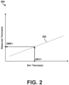
- Figure 2 is a conceptual illustration of mapping a dry thickness of a fabric preform to a debulked thickness, according to an example.
- a plot 200 of debulked thickness versus dry fabric thickness can be determined analytically or experimentally.
- the slope of trend line 202 may be less than one.
- the slope of trend line may be 0.9.
- Correlation data corresponding to the relationship shown in plot 200 can be stored for use in mapping a dry thickness of a fabric preform to a debulked thickness.
- the correlation data can take the form of a lookup table or a function that converts dry thickness to debulked thickness. Since the relationship between dry thickness and debulked thickness can vary based on the factors noted above, different instances of correlation data can be generated and stored for different configurations (e.g., different vacuum pressures, types of preforms, and/or materials).
- a computing system can use the correlation data to determine that a dry thickness DRY1 corresponds to a debulked thickness DBK1.
- the dry thickness may be 3 mm
- the debulked thickness may be 2.5 mm.
- a computing system can determine a stitch tension using the dry thickness of the fabric preform and the debulked thickness of the fabric preform. For instance, determining the stitch tension can involve determining a crimp induced deflection for the fabric preform using the dry thickness of the fabric preform and the debulked thickness of the fabric preform, and determining the stitch tension using the dry thickness of the fabric preform and the crimp induced deflection.
- the crimp induced deflection is a percentage by which the thickness of the fabric preform is reduced due to stitching with a stitch tension and debulking. As such, the crimp induced deflection is a function of the stitch tension as well as the dry thickness of a fabric preform.
- a computing system can determine the crimp induced deflection by dividing the debulked thickness of a fabric preform by the dry thickness. For instance, the crimp induced deflection for a fabric preform having a dry thickness of 3 mm and a debulked thickness of 2 mm is 66.7%.
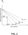
- Correlation data corresponding to the relationships shown in plot 300 can be stored for use in mapping a dry thickness of a fabric preform and crimp induced deflection to a stitch tension.
- the correlation data can take the form of a lookup table or a function that converts dry thickness and crimp induced deflection to stitch tension.
- Different instances of correlation data can be generated and stored for different configurations (e.g., different vacuum pressures, types of preforms, and/or materials).
- a computing system can use the correlation data to determine that a crimp induced deflection CID1 for a fabric preform having a dry thickness of 1 mm corresponds to a stitch tension ST1.
- the computing system can cause a stitching machine to apply a stitch having the stitch tension to the fabric preform.
- the computing system can transmit an instruction including the stitch tension to the stitching machine. Reception of the instruction can cause the stitching machine to set the stitch tension to stitch tension specified in the instruction.
- the computing system can display the stitch tension on a display, and an operator can then adjust the stitch tension of a stitching machine accordingly.
- the computing system can add the stitch tension to a map for the fabric preform that stores stitch tensions for various sections of the fabric preform.
- a stitching machine can refer to the map to determine an appropriate stitch tension for a section of the fabric preform that the stitching machine is currently stitching.
- first through-the-thickness cross-section 402 when first stitch 404 is applied using stitching machine 406, first stitch 404 is correctly applied and is substantially perpendicular to longitudinal axis L.
- second through-the-thickness cross-section 408 when second stitch 410 is subsequently applied, a needle 416 of stitching machine 406 deforms fabric preform 400 that is held by first stitch 404 and pulls fabric preform 400 closer to an insertion point at which needle 416 is inserted each time the needle is inserted.
- fabric preform 400 shears, causing second stitch 410 to be applied at an angle that is not perpendicular to longitudinal axis L.
- third through-the-thickness cross-section 412 as third stitch 414 is applied, fabric preform 400 continues to shear, such that third stitch 414 is also applied at an angle that is not perpendicular to longitudinal axis L.
- Figure 4 depicts stitching machine 406 as being stationary and fabric preform 400 being slid to the right to insert subsequent stitches, the example is not meant to be limiting. In other examples, fabric preform 400 can be held stationary while the position of stitching machine 406 is moved to insert stitches at different locations. In either scenario, shearing of fabric preform 400 can occur.
- a fabric preform can shear due to handling of the fabric preform by an operator between applications of consecutive stitches. Since an orientation of a stitch has an effect on the load carrying capability of an S/RI structure, stitching a stitch at an improper orientation can reduce the mechanical performance of the stitch relative to a stitch that is stitched at the intended orientation.
- edge-stitching Prior to performing structural stitching, additional stitching can be applied around the edge of a fabric preform, referred to as edge-stitching.
- the edge-stitching can provide resistance to shearing between layers of the fabric preform when subsequent stitches are applied. As such, the edge-stitching can help ensure that structural stitches that are subsequently applied to the fabric preform are applied at correct and consistent orientations, thereby improving mechanical performance of the resulting S/RI structure.
- edge-stitching can be strategically applied based on a shape or configuration of a fabric preform. For instance, edge-stitching can be applied within a scrap region of the fabric preform. A scrap region is a region that is designated to be removed (e.g., trimmed away) after curing the fabric preform. Further, optionally, edge-stitching can be applied with a stitch tension that is dependent upon a dry thickness of the fabric preform. For instance, edge-stitching can be applied using a stitch tension that is determined using any of the stitch tension determination methods disclosed herein.
- Figure 5 is a conceptual illustration of edge-stitching, according to an example. More specifically, Figure 5 is a top view of edge-stitching 502 that is applied within a scrap region 504 of a fabric preform 506. Scrap region 504 is located around a perimeter of fabric preform 506, and edge-stitching 502 is provided within the perimeter. As such, edge-stitching help prevent shearing of fabric preform when subsequent stitches are applied within the interior of fabric preform 506. Although fabric preform 506 is shown as a rectangular panel, the example is not meant to be limiting.
- FIG. 6 is an example stitching machine 600.
- stitching machine 600 includes a stitching unit 602, a needle casing 604, an adjustable thread tensioner 606, a tension control knob 608, an adapter plate 610, a pressure adjuster 612, a pressure control knob 614, and a computing system 616.
- Stitching unit 602 includes a user interface, one or more actuators, and a controller.
- the controller can be configured to cause the actuators to extend and retract needle casing 604 from stitching unit 602 in order to apply a stitch to a fabric preform using thread 618.
- the controller can include one or more processors coupled to a memory, and can be configured to control the actuators based on user input provided by an operator by way of the user interface.
- Needle casing 604 is configured to hold a needle 620. Thread 618 can be attached to needle 620. Extending and retracting needle casing 604 can cause needle 620 to penetrate a fabric preform such that a stitch is applied to the fabric preform.
- Adjustable thread tensioner 606 is configured to apply a predefined stitch tension to thread 618.
- Adjustable thread tensioner 606 includes a tension rod 622 extending from a side of stitching unit 602.
- Tension rod 622 is configured to apply the predefined stitch tension to thread 618.
- Tension rod 622 in turn, includes a thread support 624 configured to contact the thread.
- Thread support 624 can be a pulley, for instance.
- Adjustable thread tensioner 606 also includes a tension adjuster 626 configured to adjust the predefined stitch tension by adjusting a position of tension rod 622 relative to stitching unit 602.
- Tension adjuster 626 can include a rack and pinion that is operable using tension control knob 608 or an electric motor (not shown).
- tension adjuster 626 can extend tension rod 622 to increase stitch tension. Conversely, tension adjuster 626 can retract tension rod 622 to decrease stitch tension.
- the stitch tension can be predefined manually. For instance, an operator can define the stitch tension using tension control knob 608. Alternatively, the stitch tension can be predefined digitally.
- computing system 616 can cause tension adjuster 626 to adjust the stitch tension based on a dry thickness of a fabric preform. Computing system 616 can determine the stitch tension using any of the stitch tension determination methods disclosed herein.
- adjustable thread tensioner 606 can utilize a load feedback loop to track the applied stitch tension and dynamically maintain the stitch tension within a threshold range of a target stitch tension.
- adjustable thread tensioner 606 can include a feedback sensor 628 configured to output sensor data indicative of force applied to thread 618 by tension rod 622.
- feedback sensor 628 can be a piezoelectric sensor or force transducer coupled to tension rod 622, and can output sensor data to computing system 616.
- Computing system 616 can receive the sensor data provided by feedback sensor 628, and use the sensor data as feedback for controlling a position of tension rod 622.
- computing system 616 can use the sensor data to ensure that force applied by tension rod 622 to thread 618 remains within a threshold force range.
- computing system 616 can cause tension adjuster 626 to extend tension rod 622. Conversely, as the force applied by tension rod 622 increases, computing system 616 can cause tension adjuster 626 to retract tension rod 622.
- computing system 616 can input the stitch tension as a function of thread length. This can provide the ability to maintain a constant "strain" in the applied stitch as material thickness changes across the fabric preform.
- a thread length TL can be defined as a distance between stitching unit 602 and support surface 630.
- thread 618 may deform (e.g., stretch) by an amount that is proportional to the thread length TL.
- the distance between stitching unit 602 and support surface can be increased or decreased, such that the thread length TL also changes.
- the deformation in the thread also changes.
- computing system 616 can determine the predefined stitch tension based on the thread length TL. For instance, computing system 616 can use a lookup table to convert a desired stitch tension and a thread length TL to a modified stitch tension that accounts for thread length TL.
- Adapter plate 610 is configured to apply pressure to a fabric preform on two sides of a stitch location during stitching.
- Adapter plate can be coupled to needle casing 604 by way of a spring, such as a mechanical spring or a pneumatic spring that biases the adapter plate away from stitching unit 602 and towards a support surface 630 on which a fabric preform is positioned.
- a spring such as a mechanical spring or a pneumatic spring that biases the adapter plate away from stitching unit 602 and towards a support surface 630 on which a fabric preform is positioned.
- Pressure adjuster 612 can include a linear actuator (e.g., a rack and pinion) that is operable using pressure control knob 614 or an electric motor (not shown). In operation, pressure adjuster 612 can increase an amount by which adapter plate 610 extends from stitching unit 602 to increase the pressure. Conversely, pressure adjuster 612 can decrease the amount by which adapter plate 610 extends from stitching unit 602 to decrease the pressure.
- a linear actuator e.g., a rack and pinion
- pressure adjuster 612 can increase an amount by which adapter plate 610 extends from stitching unit 602 to increase the pressure.
- pressure adjuster 612 can decrease the amount by which adapter plate 610 extends from stitching unit 602 to decrease the pressure.
- computing system 616 can cause pressure adjuster 612 to adjust the applied pressure.
- Computing system 616 can determine the pressure to apply in various manners. As one example, computing system 616 can determine the pressure to apply based on feedback detected by a pressure sensor of pressure adjuster 612. For instance, if adapter plate 610 encounters increased resistance when moving from a thin section of the fabric preform to a thick section of a fabric preform such that the pressure sensed by the pressure sensor increases, computing system 616 can cause the pressure adjuster 612 to decrease the applied pressure. Conversely, if the pressure sensed by the pressure sensor decreases when moving from a thick section of a fabric preform to a thin section of the fabric preform, computing system 616 can cause pressure adjuster 612 to increase the applied pressure. As another example, computing system 616 can determine the pressure to apply based on map of a fabric preform that indicates thicknesses or desired pressures for different respective sections of the fabric preform.
- Adapter plate 610 includes a stitch opening through which needle 620 passes during stitching.
- Stitch opening has a width W.
- width W When needle 620 is pushed through a fabric preform having integrated fibers, it may be desirable to allow the fabric preform to deform slightly such that needle 620 does not damage the fibers. If the width W is too narrow, the fabric preform might not be able to deform enough to allow the stitch to be applied. On the other hand, if the width W is too large, adapter plate 610 might not provide enough resistance to shearing between layers of the fabric preform during stitching.
- adapter plate 610 can include a linear actuator (e.g., a worm drive) that is configured to adjust a width W of a stitch opening of adapter plate 610.
- a linear actuator e.g., a worm drive
- the width W of the stitch opening of adapter plate 610 can be adjusted to help ensure that damage is not induced during stitching.
- the width of the stitch opening of adapter plate 610 might be fixed.
- adapter plate 610 could be interchangeable with other adapter plates having stitch openings with different widths.
- FIG. 7 is an example computing system 700 for determining a stitch tension.
- Computing system 700 can take the form of a client device (e.g., a computing device that is actively operated by a user), a server, cloud computing device, or some other type of computational platform.
- client device e.g., a computing device that is actively operated by a user
- server e.g., a server
- cloud computing device e.g., a server
- computing system 700 can take the form of a desktop computer, laptop computer, tablet computer, smartphone, wearable computing device (e.g., AR glasses), or other type of device.
- wearable computing device e.g., AR glasses
- Computing system 700 includes a processor 702 and a memory 704.
- Processor 702 can be a general-purpose processor or special purpose processor (e.g., a digital signal processor, application specific integrated circuit, etc.).
- Processor 702 is configured to execute instructions 706 (e.g., computer-readable program instructions including computer executable code) that are stored in the memory 704 and are executable to provide various operations described herein.
- instructions 706 e.g., computer-readable program instructions including computer executable code
- computing system 700 can include additional processors that are configured in the same manner. At least some of the operations described herein as being performed by computing system 700 can be performed by processor 702.
- Memory 704 can take the form of one or more computer-readable storage media that can be read or accessed by processor 702.
- the computer-readable storage media can include volatile and/or non-volatile storage components, such as optical, magnetic, organic or other memory or disc storage, which can be integrated in whole or in part with processor 702.
- Memory 704 is considered non-transitory computer readable media.
- memory 704 can be implemented using a single physical device (e.g., one optical, magnetic, organic or other memory or disc storage unit), while in other examples, memory 704 can be implemented using two or more physical devices.
- Computing system 700 can be in communication with another device over a communication link.
- the communication link can take the form of any wired connection (e.g., Ethernet) or wireless connection (e.g., Bluetooth ® ) over which computing system 700 and the other device can engage in communication.
- computing system 700 can engage in communication with a stitching machine.
- computing system 700 can receive information from the stitching machine and/or transmit information to the stitching machine.
- computing system 700 can transmit a control instruction to the stitching machine to cause the stitching machine to apply a stitch having a determined stitch tension.
- computing system 700 can be an integrated component of a stitching machine.
- computing system 700 can be part of stitching machine 600 of Figure 6 .
- computing system 700 can perform any of the computing system functions described herein. For instance, computing system can determine a dry thickness of a fabric preform, determine a debulked thickness of the fabric preform, determine a stitch tension using the dry thickness of the fabric preform and the debulked thickness of the fabric preform, and cause a stitching machine to apply a stitch having the stitch tension to the fabric preform.
- Figure 8 shows a flowchart of a method 800, according to an example.
- Method 800 shown in Figure 8 presents an embodiment of a method that, for example, could be used with any of the systems disclosed herein.
- Any of the computing systems described herein, such as computing system 700 of Figure 7 may be used or configured to perform logical functions presented in Figure 8 .
- each block may represent a module, a segment, or a portion of program code, which includes one or more instructions executable by a processor for implementing specific logical functions or steps in the process.
- the program code may be stored on any type of computer readable medium or data storage, for example, such as a storage device including a disk or hard drive.
- the computer readable medium may include non-transitory computer readable medium or memory, for example, such as computer readable media that stores data for short periods of time like register memory, processor cache, and RAM.
- the computer readable media may also be any other volatile or non-volatile storage systems.
- the computer readable medium may be considered a tangible computer readable storage medium, for example.
- method 800 includes determining a dry thickness of a fabric preform.
- the fabric preform can be a fabric preform for a composite structure.
- a computing system can determine the dry thickness based on user input data provided by an operator, measurement data provided by a sensor, or thickness data stored in a map for the fabric preform.
- method 800 includes determining a debulked thickness of the fabric preform using the dry thickness of the fabric preform.
- the debulked thickness can be an expected thickness of the fabric preform after debulking the fabric preform.
- method 800 includes determining a stitch tension using the dry thickness of the fabric preform and the debulked thickness of the fabric preform. Determining the stitch tension can involve determining a stitch tension that causes a thickness of a stitch region of the stitch after debulking the fabric preform to be substantially equal to the debulked thickness of the fabric preform with the stitch being substantially linear through the thickness of the stitch region.
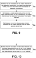
- Figure 10 shows an additional operation for use with the method shown in Figure 8 .
- Block 1002 could be performed as part of block 906 of Figure 9 .
- Figure 8 includes mapping the dry thickness of the fabric preform and the crimp induced deflection to the stitch tension using correlation data that maps dry thicknesses and crimp induced deflections to stitch tensions.
- the correlation data could be stored within a lookup table, for instance.
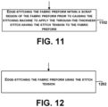
- Figure 11 shows an additional operation for use with the method shown in Figure 8 .
- Block 1102 could be performed prior to block 808 of Figure 8 .
- Figure 11 includes edge-stitching the fabric preform within a scrap region of the fabric preform prior to causing the stitching machine to apply the through-the-thickness stitch having the stitch tension to the fabric preform. Edge-stitching the fabric preform can help reduce shearing during subsequent stitching of the fabric preform.
- Figure 12 shows an additional operation for use with the method shown in Figure 8 .
- Block 1202 could be performed as part of block 1102 of Figure 11 .
- Figure 12 includes edge-stitching the fabric preform using the stitch tension.
- Figure 14 shows an additional operation for use with the method shown in Figure 8 .
- Block 1402 could be performed after block 808 of Figure 8 .
- Figure 14 includes debulking the fabric preform after causing the stitching machine to apply the through-the-thickness stitch having the stitch tension to the fabric preform.
- Debulking the fabric preform can involve applying vacuum pressure to a fabric preform in order to reduce a thickness of the fabric preform.
Landscapes
- Engineering & Computer Science (AREA)
- Physics & Mathematics (AREA)
- General Physics & Mathematics (AREA)
- Textile Engineering (AREA)
- Computer Hardware Design (AREA)
- Microelectronics & Electronic Packaging (AREA)
- General Engineering & Computer Science (AREA)
- Automation & Control Theory (AREA)
- Sewing Machines And Sewing (AREA)
- Moulding By Coating Moulds (AREA)
Claims (14)
- Verfahren (800), umfassend:Bestimmen (802), durch ein Rechensystem, einer Trockendicke eines Gewebevorformlings;Bestimmen (804), durch das Rechensystem, einer geglätteten Dicke des Gewebevorformlings unter Einsatz der Trockendicke des Gewebevorformlings;Bestimmen (806), durch das Rechensystem, einer Nahtspannung unter Einsatz der Trockendicke des Gewebevorformlings und der geglätteten Dicke des Gewebevorformlings; undBewirken (808), durch das Rechensystem, dass eine Nähmaschine eine Naht durch die Dicke mit der Nahtspannung durch den Gewebevorformling anbringt.
- Verfahren nach Anspruch 1, wobei:der Gewebevorformling ein Gewebevorformling für eine Verbundstruktur ist, unddie geglättete Dicke (T2) des Gewebevorformlings eine erwartete Dicke des Gewebevorformlings nach dem Glätten des Gewebevorformlings ist.
- Verfahren nach einem der Ansprüche 1 bis 2, wobei das Bestimmen der geglätteten Dicke des Gewebevorformlings unter Einsatz der Trockendicke des Gewebevorformling das Abbilden (902) der Trockendicke des Gewebevorformling auf die geglättete Dicke des Gewebevorformlings unter Einsatz von Korrelationsdaten umfasst, die Trockendicken auf geglättete Dicken abbilden.
- Verfahren nach einem der Ansprüche 1 bis 3, wobei das Bestimmen der Nahtspannung unter Einsatz der Trockendicke des Gewebevorformlings und der geglätteten Dicke des Gewebevorformlings umfasst:Bestimmen (904) einer crimpinduzierten Ablenkung für den Gewebevorformling unter Einsatz der Trockendicke des Gewebevorformlings und der geglätteten Dicke des Gewebevorformlings; undBestimmen (906) der Nahtspannung unter Einsatz der Trockendicke des Gewebevorformlings und der crimpinduzierten Ablenkung.
- Verfahren nach Anspruch 4, wobei:
das Bestimmen der Nahtspannung unter Einsatz der Trockendicke des Gewebevorformlings und die crimpinduzierte Ablenkung ein Abbilden (1002) der Trockendicke des Gewebevorformlings und der crimpinduzierten Ablenkung auf die Nahtspannung unter Einsatz von Korrelationsdaten umfasst, die Trockendicken auf geglättete Dicken abbilden. - Verfahren nach einem der Ansprüche 1 bis 5, ferner umfassend Kantennähen (1102) des Gewebevorformlings innerhalb einer Verschnittbereichs des Gewebevorformlings vor dem Bewirken, dass eine Nähmaschine die Naht durch die Dicke mit der Nahtspannung durch den Gewebevorformling anbringt.
- Verfahren nach Anspruch 6, wobei das Kantennähen des Gewebevorformlings Kantennähen (1202) des Gewebevorformlings unter Einsatz der Nahtspannung umfasst.
- Verfahren nach einem der Ansprüche 1 bis 7, ferner umfassend Einstellen (1302) eines mit einer Adapterplatte (610) der Nähmaschine auf den Gewebevorformling aufgebrachten Drucks vor dem Bewirken, dass eine Nähmaschine die Naht durch die Dicke mit der Nahtspannung durch den Gewebevorformling anbringt.
- Verfahren nach Anspruch 8, ferner umfassend Einstellen (1304) einer Breite einer Nahtöffnung einer Adapterplatte der Nähmaschine vor dem Bewirken, dass eine Nähmaschine die Naht durch die Dicke mit der Nahtspannung durch den Gewebevorformling anbringt.
- Verfahren nach Anspruch 1 bis 9, ferner umfassend das Glätten (1402) des Gewebevorformlings nach dem Bewirken, dass eine Nähmaschine die Naht durch die Dicke mit der Nahtspannung durch den Gewebevorformling anbringt,wobei eine Dicke (T3) eines Nahtbereichs der Naht durch die Dicke nach dem Glätten des Gewebevorformlings im Wesentlichen identisch ist mit der geglätteten Dicke (T2) des Gewebevorformlings, undwobei die Naht durch die Dicke im Wesentlichen durch die Dicke des Nahtbereichs hindurch linear ist.
- Nähmaschine (600), umfassend:eine Näheinheit (602);einen einstellbaren Fadenspanner (606), dazu konfiguriert, eine vordefinierte Nahtspannung auf einen Faden anzuwenden, um eine Naht durch die Dicke durch einen Gewebevorformling auszubilden;wobei der einstellbare Fadenspanner (606) umfasst:eine Spannstange (622), die sich von einer Seite der Näheinheit aus erstreckt und dazu konfiguriert ist, die vordefinierte Nahtspannung auf den Faden auszuüben, wobei die Spannstange einen Fadenhalter (624) umfasst, dazu konfiguriert, den Faden zu berühren; undeinen Spannungsregler (626), dazu konfiguriert, eine Position der Spannstange relativ zu der Näheinheit einzustellen;die Nähmaschine ferner umfassend ein Rechensystem (616), dazu konfiguriert, eine Trockendicke des Gewebevorformlings zu bestimmen, um zu bewirken, dass der Spannungsregler die vordefinierte Nahtspannung basierend auf einer Trockendicke des Gewebevorformlings einstellt;Bestimmen einer geglätteten Dicke des Gewebevorformlings unter Einsatz der Trockendicke des Gewebevorformlings; undBestimmen der vordefinierten Nahtspannung unter Einsatz der Trockendicke des Gewebevorformlings und der geglätteten Dicke des Gewebevorformlings.
- Nähmaschine (600) nach Anspruch 11, ferner umfassend:eine Adapterplatte (610), dazu konfiguriert, während des Nähens auf zwei Seiten einer Nahtstelle Druck auf den Gewebevorformling auszuüben; undeinen Druckregler (612), konfiguriert zum Einstellen des Drucks.
- Nähmaschine (600) nach Anspruch 11 oder 12, ferner umfassend ein Rechensystem (616), dazu konfiguriert, zu bewirken, dass der Druckregler den Druck einstellt.
- Rechensystem, umfassend:einen Prozessor; undein computerlesbares Medium, auf dem Anweisungen gespeichert sind, die ausführbar sind, um das Rechensystem zu veranlassen, die Schritte nach einem der Ansprüche 1 bis 10 auszuführen.
Applications Claiming Priority (1)
| Application Number | Priority Date | Filing Date | Title |
|---|---|---|---|
| US17/399,815 US11846055B2 (en) | 2021-08-11 | 2021-08-11 | Manufacturing processes for improved mechanical performance of stitched composites |
Publications (3)
| Publication Number | Publication Date |
|---|---|
| EP4134476A2 EP4134476A2 (de) | 2023-02-15 |
| EP4134476A3 EP4134476A3 (de) | 2023-04-26 |
| EP4134476B1 true EP4134476B1 (de) | 2025-07-09 |
Family
ID=83318975
Family Applications (1)
| Application Number | Title | Priority Date | Filing Date |
|---|---|---|---|
| EP22188075.0A Active EP4134476B1 (de) | 2021-08-11 | 2022-08-01 | Herstellungsverfahren für verbesserte mechanische leistung von genähten verbundstoffen |
Country Status (2)
| Country | Link |
|---|---|
| US (1) | US11846055B2 (de) |
| EP (1) | EP4134476B1 (de) |
Family Cites Families (7)
| Publication number | Priority date | Publication date | Assignee | Title |
|---|---|---|---|---|
| SE507831C2 (sv) * | 1993-04-21 | 1998-07-20 | Husqvarna Ab | Anordning i en symaskin |
| US5931107A (en) * | 1997-12-22 | 1999-08-03 | Mcdonnell Douglas Corporation | Advanced stitching head for making stitches in a textile article having variable thickness |
| US6198983B1 (en) * | 1997-12-22 | 2001-03-06 | Mcdonnell Douglas Corporation | Table-driven software architecture for a stitching system |
| US5953231A (en) * | 1997-12-22 | 1999-09-14 | Mcdonnell Douglas Corporation | Automated quality control for stitching of textile articles |
| US5915317A (en) * | 1997-12-22 | 1999-06-29 | Thrash; Patrick J. | Automated gantry-type stitching system |
| US8246882B2 (en) | 2003-05-02 | 2012-08-21 | The Boeing Company | Methods and preforms for forming composite members with interlayers formed of nonwoven, continuous materials |
| JP2012065855A (ja) * | 2010-09-24 | 2012-04-05 | Brother Ind Ltd | ミシン |
-
2021
- 2021-08-11 US US17/399,815 patent/US11846055B2/en active Active
-
2022
- 2022-08-01 EP EP22188075.0A patent/EP4134476B1/de active Active
Also Published As
| Publication number | Publication date |
|---|---|
| EP4134476A3 (de) | 2023-04-26 |
| US20230049264A1 (en) | 2023-02-16 |
| EP4134476A2 (de) | 2023-02-15 |
| US11846055B2 (en) | 2023-12-19 |
Similar Documents
| Publication | Publication Date | Title |
|---|---|---|
| Clancy et al. | A study of the influence of processing parameters on steering of carbon Fibre/PEEK tapes using laser-assisted tape placement | |
| Trask et al. | Influence of process induced defects on the failure of composite T-joint specimens | |
| Margossian et al. | Finite element forming simulation of locally stitched non-crimp fabrics | |
| EP2903802B1 (de) | Verfahren zur verbundbandlaminierung über konvexe radien | |
| US10814568B2 (en) | Methods for forming a composite blade stiffener and facilitating application of barely visible impact damage treatments | |
| EP2527130B1 (de) | Auflegeverfahren für unebene Komponenten von Verbundstoffmaterialien | |
| Edgren et al. | Failure of NCF composites subjected to combined compression and shear loading | |
| RU2755714C2 (ru) | Системы и способы получения композитной детали | |
| US11179900B2 (en) | Laminate shear forming machine with dynamic pressure adjustment | |
| Clancy et al. | Steering of carbon fiber/thermoplastic pre-preg tapes using laser-assisted tape placement | |
| Eberl et al. | The effect of fiber undulation on the strain field for pinned composite/titanium joints under tension | |
| Nguyen et al. | Effect of automated fiber placement (AFP) manufacturing signature on mechanical performance | |
| US10875260B2 (en) | Composite part forming system | |
| Peeters et al. | Optimal design, manufacturing and testing of non-conventional laminates | |
| EP4134476B1 (de) | Herstellungsverfahren für verbesserte mechanische leistung von genähten verbundstoffen | |
| EP4140718B1 (de) | Vorrichtung und verfahren zur ermöglichung von biegung in der ebene von verbundstrukturen hoher kontur in nachformungsvorgängen | |
| Mahfuz et al. | Integral manufacturing of composite skin-stringer assembly and their stability analyses | |
| AU2019206019B2 (en) | Method and system for tuning a tow placement system | |
| Madhok | Comparative characterization of out-of-autoclave materials made by automated fiber placement and hand-lay-up processes | |
| Cardona et al. | Manufacturing of Aircraft Structures Using Composite Tailoring Techniques. | |
| Harik et al. | Thin-ply: Exploration and manufacturing with automated fiber placement | |
| Lovejoy et al. | Tension and Bending Testing of an Integral T-cap for Stitched Composite Airframe Joints | |
| US11225036B2 (en) | Method and system for tuning a tow placement system | |
| Islam et al. | Robotic Kinematic Modeling and Deformation of Composite Laminates via Automated Fiber Placement Manufacturing | |
| Ranatunga et al. | Interlaminar fracture toughness characterization of z-pinned and flocked composite laminates |
Legal Events
| Date | Code | Title | Description |
|---|---|---|---|
| PUAI | Public reference made under article 153(3) epc to a published international application that has entered the european phase |
Free format text: ORIGINAL CODE: 0009012 |
|
| STAA | Information on the status of an ep patent application or granted ep patent |
Free format text: STATUS: THE APPLICATION HAS BEEN PUBLISHED |
|
| AK | Designated contracting states |
Kind code of ref document: A2 Designated state(s): AL AT BE BG CH CY CZ DE DK EE ES FI FR GB GR HR HU IE IS IT LI LT LU LV MC MK MT NL NO PL PT RO RS SE SI SK SM TR |
|
| RAP3 | Party data changed (applicant data changed or rights of an application transferred) |
Owner name: THE BOEING COMPANY |
|
| PUAL | Search report despatched |
Free format text: ORIGINAL CODE: 0009013 |
|
| AK | Designated contracting states |
Kind code of ref document: A3 Designated state(s): AL AT BE BG CH CY CZ DE DK EE ES FI FR GB GR HR HU IE IS IT LI LT LU LV MC MK MT NL NO PL PT RO RS SE SI SK SM TR |
|
| RIC1 | Information provided on ipc code assigned before grant |
Ipc: B32B 7/09 20190101ALI20230317BHEP Ipc: D05B 47/04 20060101AFI20230317BHEP |
|
| STAA | Information on the status of an ep patent application or granted ep patent |
Free format text: STATUS: REQUEST FOR EXAMINATION WAS MADE |
|
| 17P | Request for examination filed |
Effective date: 20231024 |
|
| RBV | Designated contracting states (corrected) |
Designated state(s): AL AT BE BG CH CY CZ DE DK EE ES FI FR GB GR HR HU IE IS IT LI LT LU LV MC MK MT NL NO PL PT RO RS SE SI SK SM TR |
|
| GRAP | Despatch of communication of intention to grant a patent |
Free format text: ORIGINAL CODE: EPIDOSNIGR1 |
|
| STAA | Information on the status of an ep patent application or granted ep patent |
Free format text: STATUS: GRANT OF PATENT IS INTENDED |
|
| RIC1 | Information provided on ipc code assigned before grant |
Ipc: B32B 7/09 20190101ALI20240221BHEP Ipc: D05B 47/04 20060101AFI20240221BHEP |
|
| INTG | Intention to grant announced |
Effective date: 20240313 |
|
| GRAJ | Information related to disapproval of communication of intention to grant by the applicant or resumption of examination proceedings by the epo deleted |
Free format text: ORIGINAL CODE: EPIDOSDIGR1 |
|
| STAA | Information on the status of an ep patent application or granted ep patent |
Free format text: STATUS: REQUEST FOR EXAMINATION WAS MADE |
|
| GRAP | Despatch of communication of intention to grant a patent |
Free format text: ORIGINAL CODE: EPIDOSNIGR1 |
|
| STAA | Information on the status of an ep patent application or granted ep patent |
Free format text: STATUS: GRANT OF PATENT IS INTENDED |
|
| INTG | Intention to grant announced |
Effective date: 20240704 |
|
| P01 | Opt-out of the competence of the unified patent court (upc) registered |
Free format text: CASE NUMBER: APP_37033/2024 Effective date: 20240620 |
|
| GRAS | Grant fee paid |
Free format text: ORIGINAL CODE: EPIDOSNIGR3 |
|
| GRAA | (expected) grant |
Free format text: ORIGINAL CODE: 0009210 |
|
| STAA | Information on the status of an ep patent application or granted ep patent |
Free format text: STATUS: THE PATENT HAS BEEN GRANTED |
|
| AK | Designated contracting states |
Kind code of ref document: B1 Designated state(s): AL AT BE BG CH CY CZ DE DK EE ES FI FR GB GR HR HU IE IS IT LI LT LU LV MC MK MT NL NO PL PT RO RS SE SI SK SM TR |
|
| REG | Reference to a national code |
Ref country code: GB Ref legal event code: FG4D |
|
| REG | Reference to a national code |
Ref country code: CH Ref legal event code: EP |
|
| REG | Reference to a national code |
Ref country code: IE Ref legal event code: FG4D |
|
| REG | Reference to a national code |
Ref country code: DE Ref legal event code: R096 Ref document number: 602022017213 Country of ref document: DE |
|
| REG | Reference to a national code |
Ref country code: NL Ref legal event code: FP |
|
| PGFP | Annual fee paid to national office [announced via postgrant information from national office to epo] |
Ref country code: NL Payment date: 20250826 Year of fee payment: 4 |
|
| PGFP | Annual fee paid to national office [announced via postgrant information from national office to epo] |
Ref country code: DE Payment date: 20250827 Year of fee payment: 4 |
|
| PGFP | Annual fee paid to national office [announced via postgrant information from national office to epo] |
Ref country code: FR Payment date: 20250825 Year of fee payment: 4 Ref country code: AT Payment date: 20251020 Year of fee payment: 4 |
|
| PG25 | Lapsed in a contracting state [announced via postgrant information from national office to epo] |
Ref country code: PT Free format text: LAPSE BECAUSE OF FAILURE TO SUBMIT A TRANSLATION OF THE DESCRIPTION OR TO PAY THE FEE WITHIN THE PRESCRIBED TIME-LIMIT Effective date: 20251110 |
|
| REG | Reference to a national code |
Ref country code: AT Ref legal event code: MK05 Ref document number: 1811907 Country of ref document: AT Kind code of ref document: T Effective date: 20250709 |
|
| PG25 | Lapsed in a contracting state [announced via postgrant information from national office to epo] |
Ref country code: IS Free format text: LAPSE BECAUSE OF FAILURE TO SUBMIT A TRANSLATION OF THE DESCRIPTION OR TO PAY THE FEE WITHIN THE PRESCRIBED TIME-LIMIT Effective date: 20251109 |
|
| PG25 | Lapsed in a contracting state [announced via postgrant information from national office to epo] |
Ref country code: NO Free format text: LAPSE BECAUSE OF FAILURE TO SUBMIT A TRANSLATION OF THE DESCRIPTION OR TO PAY THE FEE WITHIN THE PRESCRIBED TIME-LIMIT Effective date: 20251009 |
|
| REG | Reference to a national code |
Ref country code: LT Ref legal event code: MG9D |
|
| PG25 | Lapsed in a contracting state [announced via postgrant information from national office to epo] |
Ref country code: AT Free format text: LAPSE BECAUSE OF FAILURE TO SUBMIT A TRANSLATION OF THE DESCRIPTION OR TO PAY THE FEE WITHIN THE PRESCRIBED TIME-LIMIT Effective date: 20250709 |
|
| PG25 | Lapsed in a contracting state [announced via postgrant information from national office to epo] |
Ref country code: FI Free format text: LAPSE BECAUSE OF FAILURE TO SUBMIT A TRANSLATION OF THE DESCRIPTION OR TO PAY THE FEE WITHIN THE PRESCRIBED TIME-LIMIT Effective date: 20250709 |
|
| PG25 | Lapsed in a contracting state [announced via postgrant information from national office to epo] |
Ref country code: HR Free format text: LAPSE BECAUSE OF FAILURE TO SUBMIT A TRANSLATION OF THE DESCRIPTION OR TO PAY THE FEE WITHIN THE PRESCRIBED TIME-LIMIT Effective date: 20250709 |
|
| PG25 | Lapsed in a contracting state [announced via postgrant information from national office to epo] |
Ref country code: GR Free format text: LAPSE BECAUSE OF FAILURE TO SUBMIT A TRANSLATION OF THE DESCRIPTION OR TO PAY THE FEE WITHIN THE PRESCRIBED TIME-LIMIT Effective date: 20251010 |
|
| PG25 | Lapsed in a contracting state [announced via postgrant information from national office to epo] |
Ref country code: SE Free format text: LAPSE BECAUSE OF FAILURE TO SUBMIT A TRANSLATION OF THE DESCRIPTION OR TO PAY THE FEE WITHIN THE PRESCRIBED TIME-LIMIT Effective date: 20250709 |
|
| PG25 | Lapsed in a contracting state [announced via postgrant information from national office to epo] |
Ref country code: LV Free format text: LAPSE BECAUSE OF FAILURE TO SUBMIT A TRANSLATION OF THE DESCRIPTION OR TO PAY THE FEE WITHIN THE PRESCRIBED TIME-LIMIT Effective date: 20250709 |
|
| PG25 | Lapsed in a contracting state [announced via postgrant information from national office to epo] |
Ref country code: BG Free format text: LAPSE BECAUSE OF FAILURE TO SUBMIT A TRANSLATION OF THE DESCRIPTION OR TO PAY THE FEE WITHIN THE PRESCRIBED TIME-LIMIT Effective date: 20250709 Ref country code: PL Free format text: LAPSE BECAUSE OF FAILURE TO SUBMIT A TRANSLATION OF THE DESCRIPTION OR TO PAY THE FEE WITHIN THE PRESCRIBED TIME-LIMIT Effective date: 20250709 |
|
| PG25 | Lapsed in a contracting state [announced via postgrant information from national office to epo] |
Ref country code: RS Free format text: LAPSE BECAUSE OF FAILURE TO SUBMIT A TRANSLATION OF THE DESCRIPTION OR TO PAY THE FEE WITHIN THE PRESCRIBED TIME-LIMIT Effective date: 20251009 |
|
| PG25 | Lapsed in a contracting state [announced via postgrant information from national office to epo] |
Ref country code: ES Free format text: LAPSE BECAUSE OF FAILURE TO SUBMIT A TRANSLATION OF THE DESCRIPTION OR TO PAY THE FEE WITHIN THE PRESCRIBED TIME-LIMIT Effective date: 20250709 |
|
| PG25 | Lapsed in a contracting state [announced via postgrant information from national office to epo] |
Ref country code: RO Free format text: LAPSE BECAUSE OF FAILURE TO SUBMIT A TRANSLATION OF THE DESCRIPTION OR TO PAY THE FEE WITHIN THE PRESCRIBED TIME-LIMIT Effective date: 20250709 |
|
| REG | Reference to a national code |
Ref country code: CH Ref legal event code: H13 Free format text: ST27 STATUS EVENT CODE: U-0-0-H10-H13 (AS PROVIDED BY THE NATIONAL OFFICE) Effective date: 20260324 |
|
| PG25 | Lapsed in a contracting state [announced via postgrant information from national office to epo] |
Ref country code: SM Free format text: LAPSE BECAUSE OF FAILURE TO SUBMIT A TRANSLATION OF THE DESCRIPTION OR TO PAY THE FEE WITHIN THE PRESCRIBED TIME-LIMIT Effective date: 20250709 |
|
| PG25 | Lapsed in a contracting state [announced via postgrant information from national office to epo] |
Ref country code: DK Free format text: LAPSE BECAUSE OF FAILURE TO SUBMIT A TRANSLATION OF THE DESCRIPTION OR TO PAY THE FEE WITHIN THE PRESCRIBED TIME-LIMIT Effective date: 20250709 |
|
| PG25 | Lapsed in a contracting state [announced via postgrant information from national office to epo] |
Ref country code: LU Free format text: LAPSE BECAUSE OF NON-PAYMENT OF DUE FEES Effective date: 20250801 Ref country code: IT Free format text: LAPSE BECAUSE OF FAILURE TO SUBMIT A TRANSLATION OF THE DESCRIPTION OR TO PAY THE FEE WITHIN THE PRESCRIBED TIME-LIMIT Effective date: 20250709 |
|
| PG25 | Lapsed in a contracting state [announced via postgrant information from national office to epo] |
Ref country code: CZ Free format text: LAPSE BECAUSE OF FAILURE TO SUBMIT A TRANSLATION OF THE DESCRIPTION OR TO PAY THE FEE WITHIN THE PRESCRIBED TIME-LIMIT Effective date: 20250709 Ref country code: CH Free format text: LAPSE BECAUSE OF NON-PAYMENT OF DUE FEES Effective date: 20250831 |
|
| PG25 | Lapsed in a contracting state [announced via postgrant information from national office to epo] |
Ref country code: EE Free format text: LAPSE BECAUSE OF FAILURE TO SUBMIT A TRANSLATION OF THE DESCRIPTION OR TO PAY THE FEE WITHIN THE PRESCRIBED TIME-LIMIT Effective date: 20250709 Ref country code: SK Free format text: LAPSE BECAUSE OF FAILURE TO SUBMIT A TRANSLATION OF THE DESCRIPTION OR TO PAY THE FEE WITHIN THE PRESCRIBED TIME-LIMIT Effective date: 20250709 |