EP4134408A1 - Swelling tape for secondary battery and cylindrical secondary battery comprising same - Google Patents
Swelling tape for secondary battery and cylindrical secondary battery comprising same Download PDFInfo
- Publication number
- EP4134408A1 EP4134408A1 EP21785670.7A EP21785670A EP4134408A1 EP 4134408 A1 EP4134408 A1 EP 4134408A1 EP 21785670 A EP21785670 A EP 21785670A EP 4134408 A1 EP4134408 A1 EP 4134408A1
- Authority
- EP
- European Patent Office
- Prior art keywords
- layer
- swelling
- secondary battery
- electrode assembly
- adhesive
- Prior art date
- Legal status (The legal status is an assumption and is not a legal conclusion. Google has not performed a legal analysis and makes no representation as to the accuracy of the status listed.)
- Pending
Links
Images


Classifications
-
- H—ELECTRICITY
- H01—ELECTRIC ELEMENTS
- H01M—PROCESSES OR MEANS, e.g. BATTERIES, FOR THE DIRECT CONVERSION OF CHEMICAL ENERGY INTO ELECTRICAL ENERGY
- H01M10/00—Secondary cells; Manufacture thereof
- H01M10/04—Construction or manufacture in general
- H01M10/0431—Cells with wound or folded electrodes
-
- C—CHEMISTRY; METALLURGY
- C09—DYES; PAINTS; POLISHES; NATURAL RESINS; ADHESIVES; COMPOSITIONS NOT OTHERWISE PROVIDED FOR; APPLICATIONS OF MATERIALS NOT OTHERWISE PROVIDED FOR
- C09J—ADHESIVES; NON-MECHANICAL ASPECTS OF ADHESIVE PROCESSES IN GENERAL; ADHESIVE PROCESSES NOT PROVIDED FOR ELSEWHERE; USE OF MATERIALS AS ADHESIVES
- C09J1/00—Adhesives based on inorganic constituents
-
- C—CHEMISTRY; METALLURGY
- C09—DYES; PAINTS; POLISHES; NATURAL RESINS; ADHESIVES; COMPOSITIONS NOT OTHERWISE PROVIDED FOR; APPLICATIONS OF MATERIALS NOT OTHERWISE PROVIDED FOR
- C09J—ADHESIVES; NON-MECHANICAL ASPECTS OF ADHESIVE PROCESSES IN GENERAL; ADHESIVE PROCESSES NOT PROVIDED FOR ELSEWHERE; USE OF MATERIALS AS ADHESIVES
- C09J7/00—Adhesives in the form of films or foils
- C09J7/20—Adhesives in the form of films or foils characterised by their carriers
- C09J7/201—Adhesives in the form of films or foils characterised by their carriers characterised by the release coating composition on the carrier layer
-
- C—CHEMISTRY; METALLURGY
- C09—DYES; PAINTS; POLISHES; NATURAL RESINS; ADHESIVES; COMPOSITIONS NOT OTHERWISE PROVIDED FOR; APPLICATIONS OF MATERIALS NOT OTHERWISE PROVIDED FOR
- C09J—ADHESIVES; NON-MECHANICAL ASPECTS OF ADHESIVE PROCESSES IN GENERAL; ADHESIVE PROCESSES NOT PROVIDED FOR ELSEWHERE; USE OF MATERIALS AS ADHESIVES
- C09J7/00—Adhesives in the form of films or foils
- C09J7/30—Adhesives in the form of films or foils characterised by the adhesive composition
-
- H—ELECTRICITY
- H01—ELECTRIC ELEMENTS
- H01M—PROCESSES OR MEANS, e.g. BATTERIES, FOR THE DIRECT CONVERSION OF CHEMICAL ENERGY INTO ELECTRICAL ENERGY
- H01M10/00—Secondary cells; Manufacture thereof
- H01M10/04—Construction or manufacture in general
- H01M10/0422—Cells or battery with cylindrical casing
-
- H—ELECTRICITY
- H01—ELECTRIC ELEMENTS
- H01M—PROCESSES OR MEANS, e.g. BATTERIES, FOR THE DIRECT CONVERSION OF CHEMICAL ENERGY INTO ELECTRICAL ENERGY
- H01M50/00—Constructional details or processes of manufacture of the non-active parts of electrochemical cells other than fuel cells, e.g. hybrid cells
- H01M50/10—Primary casings, jackets or wrappings of a single cell or a single battery
- H01M50/102—Primary casings, jackets or wrappings of a single cell or a single battery characterised by their shape or physical structure
- H01M50/107—Primary casings, jackets or wrappings of a single cell or a single battery characterised by their shape or physical structure having curved cross-section, e.g. round or elliptic
-
- H—ELECTRICITY
- H01—ELECTRIC ELEMENTS
- H01M—PROCESSES OR MEANS, e.g. BATTERIES, FOR THE DIRECT CONVERSION OF CHEMICAL ENERGY INTO ELECTRICAL ENERGY
- H01M50/00—Constructional details or processes of manufacture of the non-active parts of electrochemical cells other than fuel cells, e.g. hybrid cells
- H01M50/40—Separators; Membranes; Diaphragms; Spacing elements inside cells
- H01M50/471—Spacing elements inside cells other than separators, membranes or diaphragms; Manufacturing processes thereof
- H01M50/474—Spacing elements inside cells other than separators, membranes or diaphragms; Manufacturing processes thereof characterised by their position inside the cells
-
- H—ELECTRICITY
- H01—ELECTRIC ELEMENTS
- H01M—PROCESSES OR MEANS, e.g. BATTERIES, FOR THE DIRECT CONVERSION OF CHEMICAL ENERGY INTO ELECTRICAL ENERGY
- H01M50/00—Constructional details or processes of manufacture of the non-active parts of electrochemical cells other than fuel cells, e.g. hybrid cells
- H01M50/40—Separators; Membranes; Diaphragms; Spacing elements inside cells
- H01M50/471—Spacing elements inside cells other than separators, membranes or diaphragms; Manufacturing processes thereof
- H01M50/48—Spacing elements inside cells other than separators, membranes or diaphragms; Manufacturing processes thereof characterised by the material
-
- H—ELECTRICITY
- H01—ELECTRIC ELEMENTS
- H01M—PROCESSES OR MEANS, e.g. BATTERIES, FOR THE DIRECT CONVERSION OF CHEMICAL ENERGY INTO ELECTRICAL ENERGY
- H01M50/00—Constructional details or processes of manufacture of the non-active parts of electrochemical cells other than fuel cells, e.g. hybrid cells
- H01M50/40—Separators; Membranes; Diaphragms; Spacing elements inside cells
- H01M50/489—Separators, membranes, diaphragms or spacing elements inside the cells, characterised by their physical properties, e.g. swelling degree, hydrophilicity or shut down properties
-
- C—CHEMISTRY; METALLURGY
- C09—DYES; PAINTS; POLISHES; NATURAL RESINS; ADHESIVES; COMPOSITIONS NOT OTHERWISE PROVIDED FOR; APPLICATIONS OF MATERIALS NOT OTHERWISE PROVIDED FOR
- C09J—ADHESIVES; NON-MECHANICAL ASPECTS OF ADHESIVE PROCESSES IN GENERAL; ADHESIVE PROCESSES NOT PROVIDED FOR ELSEWHERE; USE OF MATERIALS AS ADHESIVES
- C09J2203/00—Applications of adhesives in processes or use of adhesives in the form of films or foils
- C09J2203/33—Applications of adhesives in processes or use of adhesives in the form of films or foils for batteries or fuel cells
-
- C—CHEMISTRY; METALLURGY
- C09—DYES; PAINTS; POLISHES; NATURAL RESINS; ADHESIVES; COMPOSITIONS NOT OTHERWISE PROVIDED FOR; APPLICATIONS OF MATERIALS NOT OTHERWISE PROVIDED FOR
- C09J—ADHESIVES; NON-MECHANICAL ASPECTS OF ADHESIVE PROCESSES IN GENERAL; ADHESIVE PROCESSES NOT PROVIDED FOR ELSEWHERE; USE OF MATERIALS AS ADHESIVES
- C09J2400/00—Presence of inorganic and organic materials
- C09J2400/10—Presence of inorganic materials
- C09J2400/12—Ceramic
-
- C—CHEMISTRY; METALLURGY
- C09—DYES; PAINTS; POLISHES; NATURAL RESINS; ADHESIVES; COMPOSITIONS NOT OTHERWISE PROVIDED FOR; APPLICATIONS OF MATERIALS NOT OTHERWISE PROVIDED FOR
- C09J—ADHESIVES; NON-MECHANICAL ASPECTS OF ADHESIVE PROCESSES IN GENERAL; ADHESIVE PROCESSES NOT PROVIDED FOR ELSEWHERE; USE OF MATERIALS AS ADHESIVES
- C09J2405/00—Presence of polysaccharides
-
- C—CHEMISTRY; METALLURGY
- C09—DYES; PAINTS; POLISHES; NATURAL RESINS; ADHESIVES; COMPOSITIONS NOT OTHERWISE PROVIDED FOR; APPLICATIONS OF MATERIALS NOT OTHERWISE PROVIDED FOR
- C09J—ADHESIVES; NON-MECHANICAL ASPECTS OF ADHESIVE PROCESSES IN GENERAL; ADHESIVE PROCESSES NOT PROVIDED FOR ELSEWHERE; USE OF MATERIALS AS ADHESIVES
- C09J2433/00—Presence of (meth)acrylic polymer
-
- C—CHEMISTRY; METALLURGY
- C09—DYES; PAINTS; POLISHES; NATURAL RESINS; ADHESIVES; COMPOSITIONS NOT OTHERWISE PROVIDED FOR; APPLICATIONS OF MATERIALS NOT OTHERWISE PROVIDED FOR
- C09J—ADHESIVES; NON-MECHANICAL ASPECTS OF ADHESIVE PROCESSES IN GENERAL; ADHESIVE PROCESSES NOT PROVIDED FOR ELSEWHERE; USE OF MATERIALS AS ADHESIVES
- C09J2475/00—Presence of polyurethane
-
- Y—GENERAL TAGGING OF NEW TECHNOLOGICAL DEVELOPMENTS; GENERAL TAGGING OF CROSS-SECTIONAL TECHNOLOGIES SPANNING OVER SEVERAL SECTIONS OF THE IPC; TECHNICAL SUBJECTS COVERED BY FORMER USPC CROSS-REFERENCE ART COLLECTIONS [XRACs] AND DIGESTS
- Y02—TECHNOLOGIES OR APPLICATIONS FOR MITIGATION OR ADAPTATION AGAINST CLIMATE CHANGE
- Y02E—REDUCTION OF GREENHOUSE GAS [GHG] EMISSIONS, RELATED TO ENERGY GENERATION, TRANSMISSION OR DISTRIBUTION
- Y02E60/00—Enabling technologies; Technologies with a potential or indirect contribution to GHG emissions mitigation
- Y02E60/10—Energy storage using batteries
-
- Y—GENERAL TAGGING OF NEW TECHNOLOGICAL DEVELOPMENTS; GENERAL TAGGING OF CROSS-SECTIONAL TECHNOLOGIES SPANNING OVER SEVERAL SECTIONS OF THE IPC; TECHNICAL SUBJECTS COVERED BY FORMER USPC CROSS-REFERENCE ART COLLECTIONS [XRACs] AND DIGESTS
- Y02—TECHNOLOGIES OR APPLICATIONS FOR MITIGATION OR ADAPTATION AGAINST CLIMATE CHANGE
- Y02P—CLIMATE CHANGE MITIGATION TECHNOLOGIES IN THE PRODUCTION OR PROCESSING OF GOODS
- Y02P70/00—Climate change mitigation technologies in the production process for final industrial or consumer products
- Y02P70/50—Manufacturing or production processes characterised by the final manufactured product
Definitions
- the present invention relates to a swelling tape for a secondary battery and a cylindrical type secondary battery including the same.
- a lithium secondary battery has an operating voltage of about 3.6V, wherein, since it has a capacity of about three times that of a nickel-cadmium battery or nickel-hydrogen battery, which is frequently used as a power source of electronic equipment, and has high energy density per unit weight, there is a tendency that a degree of utilization of the lithium secondary battery increases rapidly.
- a lithium secondary battery is composed of an electrode assembly, in which a positive electrode plate coated with a positive electrode active material and a negative electrode plate coated with a negative electrode active material are disposed with a separator disposed therebetween, an electrolyte, and a case that seals and accommodates them together.
- the lithium secondary battery may be classified into a can type secondary battery and a pouch type secondary battery according to a shape of the battery case.
- the can type secondary battery may be further classified into a cylindrical type secondary battery and a prismatic type secondary battery according to a shape of a metal can, and may be prepared by accommodating a jelly-roll type electrode assembly, in which a positive electrode, a separator, and a negative electrode are wound, in the metal can.
- the pouch type secondary battery may be prepared by placing a stacked type electrode assembly, in which a plurality of positive electrodes, separators, and negative electrodes are sequentially stacked, in a pouch composed of an aluminum laminate sheet, and then sealing the pouch.
- the lithium secondary battery may be accommodated in machines which are frequently mobile and subjected to strong vibrations like automobiles, portability and strong vibration-resistant properties are required.
- the electrode assembly is formed in a smaller size than a cylindrical battery case (metal can) in order to accommodate the electrode assembly inside the cylindrical battery case, a gap is formed between the electrode assembly and an inner wall of the battery case. This gap causes the electrode assembly to move up and down or left and right in the battery case when vibration or impact is applied from the outside due to a fall or the like.
- the movement of the electrode assembly may increase internal resistance of the battery or may cause a power insensitive phenomenon of the secondary battery due to cutting of a tab connected between the electrode assembly and a cap assembly.
- a sealing portion may be damaged or separated by applying an impact to the cap assembly coupled to an upper end opening of the secondary battery, a problem of leaking the electrolyte in the secondary battery may occur.
- a swelling tape composed of an adhesive layer 110 and a swelling layer 120 is attached to an outer circumferential surface of a jelly-roll type electrode assembly 100, in which a positive electrode, a separator, and a negative electrode are wound, and this is accommodated in a cylindrical battery case, the swelling layer expands and fills a gap existing between the electrode assembly and the battery case, and thus, the movement of the electrode assembly may be prevented.
- a urethane resin such as conventional thermoplastic polyurethane (TPU) or curable urethane, is being used as the swelling layer.
- TPU thermoplastic polyurethane
- curable urethane curable urethane
- An aspect of the present invention provides a swelling tape for a secondary battery which may effectively prevent movement of an electrode assembly in a battery.
- Another aspect of the present invention provides an electrode assembly, in which the swelling tape for a secondary battery is attached to an outer circumferential surface of the electrode assembly, and a cylindrical type secondary battery including the same.
- a swelling tape for a secondary battery which includes: a base layer and an adhesive swelling layer, wherein the adhesive swelling layer contains a water-based self-healing binder.
- the swelling tape for a secondary battery may further include at least one layer selected from an adhesive layer and a back coating layer.
- an electrode assembly in which the swelling tape for a secondary battery is attached to an outer circumferential surface of the electrode assembly.
- a cylindrical type secondary battery which includes: the electrode assembly, an electrolyte, and a cylindrical battery case accommodating the electrode assembly and the electrolyte.
- a swelling tape of the present invention includes an adhesive swelling layer containing a water-based self-healing binder on at least one surface of both surfaces of a base layer, it prevents unwinding of an electrode assembly in a wound state and simultaneously fills a gap between the electrode assembly and an inner wall of a battery case at a low cost, and, thus, it may effectively prevent movement of the electrode assembly. Accordingly, it may prevent a secondary battery from being damaged, ignited, and exploded due to a short circuit caused by deformation of the electrode assembly, and may also prevent electrolyte leakage due to damage to a coupling portion of a cap assembly. As a result, a secondary battery having high stability and effectively improved resistance increase rate and power insensitive phenomenon may be achieved.
- swelling tape in the present specification may mean a tape which is located in a gap between two objects spaced apart from each other to fill the gap and play a role in being able to fix the two objects to each other, if necessary.
- the swelling tape in a state in which the swelling tape is attached to any one of the two objects through an adhesive layer, the swelling tape refers to a tape which may achieve a three-dimensional shape capable of filling the gap by a mutual balance between a force generated by expansion of a swelling layer and a fixing force of the adhesive layer.
- a swelling tape according to the present invention includes a base layer and an adhesive swelling layer, wherein the adhesive swelling layer may contain a water-based self-healing binder.
- the base layer is a layer in the form of a film or sheet having deformation (expansion) properties when it is in contact with a fluid like a liquid such as an electrolyte, wherein it may have a shape, such as a circular, triangular, or amorphous shape, in addition to a square shape.
- the base layer may specifically include at least one polymer material selected from polyacrylate, thermoplastic polyurethane (TPU), polyvinyl chloride, polyethylene terephthalate, polyethylene, polypropylene, polyamide, polycarbonate, polyimide, and polystyrene, and may preferably include at least one selected from the group consisting of polyurethane and polystyrene.
- TPU thermoplastic polyurethane
- polyvinyl chloride polyethylene terephthalate
- polyethylene polypropylene
- polyamide polycarbonate
- polyimide polystyrene
- a thickness of the base layer may be selected in consideration of the three-dimensional shape to be achieved or a size of the gap to be filled, and the base layer may be specifically formed to a thickness of 10 um to 40 ⁇ m, for example, 20 um to 40 ⁇ m.
- the adhesive swelling layer of the present invention is a layer capable of filling the gap between the electrode assembly and a battery case by swelling when the electrolyte is impregnated or heat is applied, wherein it may achieve a maximum volume increase rate of 100% or more.
- a water-based self-healing binder having a glass transition temperature of -50°C to -30°C may be included as a component of the adhesive swelling layer.
- the water-based self-healing binder is a polymer having a property of swelling (expansion) by being in contact with an organic solvent contained in the electrolyte, or swelling by heat, etc., wherein, as a representative example thereof, it may include at least one compound selected from a ceramic matrix composite (CMC), alginate, and chitosan.
- the water-based self-healing binder may include at least one compound selected from the group consisting of a lginate and chitosan.
- the alginate as a very high molecular weight polymer, has excellent self-recovery ability, it has an excellent effect of filling the internal gap during impact when it is used in the swelling tape, and thus, it may effectively suppress the movement of the electrode assembly.
- the alginate since it has a strong anion component in a side chain, it is advantageous in that battery operating characteristics may be expressed even under an electric field by facilitating ion movement in the electrolyte.
- the alginate specifically means sodium alginate, and, in addition, ethyl lauroyl alginate or propylene glycol alginate may be used.
- the chitosan is an environmentally friendly material, wherein, since it is not only inexpensive, but also contains a large amount of hydroxy groups, it is advantageous in that binding performance is excellent.
- a secondary battery having excellent processability and reduced manufacturing costs may be prepared.
- the chitosan contains a nitrogen element in its structure, oxygen adsorption and decomposition ability are improved due to an oxygen reduction reaction by nitrogen atoms when the chitosan is used in the swelling tape, and thus, electrical conductivity of the secondary battery may be further improved.
- the use of an additional adhesive such as an acrylic pressure sensitive adhesive (PSA) may be omitted and the gap between the electrode assembly and the battery case may be completely filled by physical properties expanding due to heat or impact.
- PSA acrylic pressure sensitive adhesive
- the adhesive swelling layer may be formed on at least one surface of both surfaces of the base layer.
- the adhesive swelling layer may be prepared by coating the base layer with the binder composition and drying the coated base layer.
- the adhesive swelling layer may be formed to a thickness of about 10% to 50%, for example, 10% to 30% of a total thickness of the base layer.
- the gap between the electrode assembly (jelly roll typ e) and the battery case may be filled to provide a battery that is resistant to an external impact such as vibration. That is, in the case that the thickness of the adhesive swelling layer is about 10% or more with respect to the total thickness of the base layer, a purpose of preventing the movement of the electrode assembly may be achieved by sufficiently filling the gap.
- the thickness of the adhesive swelling layer is greater than about 50% of the total thickness of the base layer, since an outer diameter of the electrode assembly (J/R) is increased due to an increase in the thickness of the swelling tape, battery deformation occurs due to the expansion of the electrode assembly during a cycle operation, and thus, cell performance may be degraded.
- the adhesive swelling layer may be formed in an area ranging from 50% to 99%, for example, 70% to 95% of a total area of one surface of the base layer.
- the area of the adhesive swelling layer satisfies the above range, cost-effective vibration resistance may be achieved. If, in a case in which the area of the adhesive swelling layer is greater than 99% of the total area of the base layer, it is not economically favorable, and, in a case in which the area of the adhesive swelling layer is less than 50%, since the area of the adhesive swelling layer is excessively small, an effect of preventing the movement of the electrode assembly may be insignificant.
- the swelling tape of the present invention may further include at least one layer selected from an adhesive layer and a back coating layer, which will be described later, if necessary, in order to further improve adhesion and swelling effects.
- the adhesive layer is a layer added to further improve adhesion of the swelling tape to the electrode assembly, wherein it may be designed to achieve an appropriate adhesive force, in other words, an appropriate peeling force, to the electrode assembly.
- the peeling force of the adhesive layer may be changed according to the size of the three-dimensional shape to be achieved or the gap to be filled, wherein a lower limit thereof may be 100 gf/25mm or more, 200 gf/25mm or more, 400 gf/25mm or more, 600 gf/25mm or more, 800 gf/25mm or more, 1,000 gf/25mm or more, 1,200 gf/25mm or more, 1,400 gf/25mm or more, 1,600 gf/25mm or more, or 1,800 gf/25mm or more.
- an upper limit of the peeling force of the adhesive layer is not particularly limited as long as it has a general range, but may be approximately 5,000 gf/25mm or less.
- the peeling force is a peeling force measured at room temperature, and is a result measured at a peeling rate of 5 mm/sec and a peeling angle of 180°.
- the "room temperature” is a natural temperature that is not heated or cooled, wherein, for example, it may mean a temperature of about 10°C to about 30°C, particularly about 20°C to about 30°C, and more particularly about 25°C.
- the peeling force of the adhesive layer is greater than the above range, it may be difficult to achieve the three-dimensional shape by excessively suppressing deformation of the swelling layer. Also, when the peeling force of the adhesive layer is less than the above range, an effect of achieving adhesiveness to be secured when the swelling tape is expanded may be insignificant.
- the adhesive layer may include an acrylic polymer having a weight-average molecular weight (Mw) of 400,000 or more.
- the acrylic polymer may include a polymer in a form in which a (meth) acrylic acid ester monomer and a copolymerizable monomer having a crosslinkable functional group are polymerized.
- a weight ratio of each monomer is not particularly limited, and may be appropriately designed in consideration of a desired peeling force.
- An alkyl (meth)acrylate having an alkyl group having 1 to 15 carbon atoms may be used as the (meth) acrylic acid ester monomer in consideration of cohesion of the adhesive, glass transition temperature, or adhesiveness.
- the monomer one, such as methyl (meth)acrylate, ethyl (meth)acrylate, n-propyl (meth)acrylate, isopropyl (meth)acrylate, n-butyl (meth)acrylate, t-butyl (meth) acrylate, sec-butyl (meth)acrylate, pentyl (meth)acrylate, 2-ethylhexyl (meth)acrylate, 2-ethylbutyl (meth)acrylate, n-octyl (meth)acrylate, isooctyl (meth)acrylate, isononyl (meth)acrylate, lauryl (meth)acrylate, and tetradecyl (me
- the copolymerizable monomer having a crosslinkable functional group may include a monomer which may be copolymerized with the (meth)acrylic acid ester monomer through crosslinking and may provide a crosslinking point capable of reacting with a multifunctional crosslinking agent in a main chain of the polymer after the copolymerization.
- the crosslinkable functional group may be a hydroxy group, a carboxyl group, an isocyanate group, a glycidyl group or an amide group, and, in some cases, may be a photocrosslinkable functional group such as an acryloyl group or a methacryloyl group.
- Typical examples of the copolymerizable monomer having a crosslinkable functional group may be monomers having a hydroxy group such as 2-hydroxyethyl (meth)acrylate, 2-hydroxypropyl (meth)acrylate, 4-hydroxybutyl (meth)acrylate, 6-hydroxyhexyl (meth)acrylate, 8-hydroxyoctyl (meth)acrylate, 2-hydroxyethylene glycol (meth)acrylate, or 2-hydroxypropylene glycol (meth)acrylate; monomers having a carboxyl group such as (meth)acrylic acid, 2-(meth)acryloyloxy acetic acid, 3-(meth)acryloyloxy propyl acid, 4-(meth)acryloyloxy butyl acid, acrylic acid duplex, itaconic acid, maleic acid, and maleic anhydride; glycidyl (meth)acrylate, (meth)acrylamide, N-vinyl pyrrolidone, or N-vinyl caprolactam,
- the adhesive layer may be formed to a thickness of 5 ⁇ m to 20 ⁇ m, for example, 10 ⁇ m to 20 ⁇ m. If the thickness of the adhesive layer is greater than 20 um, since the outer diameter (volume) of the jelly-roll type electrode assembly is increased to reduce dispersibility of the electrolyte due to productivity problems and a decrease in space in the cell, safety and overall performance of the secondary battery may be degraded.
- the adhesive layer may be formed i) between the base layer and the adhesive swelling layer, or may be formed ii) on at least one surface selected from the base layer and the adhesive swelling layer in order to secure more improved adhesiveness.
- the back coating layer is a layer added to further improve the gap filling effect, wherein it may be formed of a thermosetting adhesive material which swells while an orientation is partially reduced by contact and impregnation with the electrolyte, or exhibits adhesiveness when heat is applied in a predetermined amount or more.
- the back coating layer may include a single material selected from the group consisting of polyimide, polybuthylene terephthalate (PBT), polyamideimide (PAI), perfluoroalkoxy (PFA), polysulfone (PSF), polyarylsulfone (PAS), polytetrafluoroethylene (PTFE), fluorinated ethylene propylene (FEP), ethylenetetrafluoroethylene (ETFE), and polyethylene naphthalene (PEN), or a mixture of two or more thereof.
- PBT polybuthylene terephthalate
- PAI polyamideimide
- PFA perfluoroalkoxy
- PSF polysulfone
- PAS polyarylsulfone
- PTFE polytetrafluoroethylene
- FEP fluorinated ethylene propylene
- ETFE ethylenetetrafluoroethylene
- PEN polyethylene naphthalene
- the adhesiveness is expressed by heat, the adhesiveness is not expressed when the electrode assembly, to which the swelling tape using the back coating layer is attached, is inserted into a battery case, and thus, the electrode assembly may be easily accommodated.
- the gap may be filled while the back coating layer expands.
- a heat application process is performed in a preparation process of the secondary battery, since the adhesiveness of the back coating layer is expressed, the movement of the electrode assembly may be more effectively improved while the adhesion of the swelling tape is improved.
- the heat application process may be an aging process performed during a conventional secondary battery preparation process, or a separate additional process may be added.
- the back coating layer may be formed i) between the base layer and the adhesive swelling layer, or may be formed ii) on the adhesive swelling layer in order to secure more improved adhesiveness.
- the swelling tape of the present invention is formed to a total thickness of 200 um or less, particularly 20 um to 200 ⁇ m, and more particularly 20 um to 150 ⁇ m, for example, 40 um to 120 um. If, in a case in which the thickness of the swelling tape is less than 20 ⁇ m, since it is difficult to secure a sufficient thickness even by the heat or the contact with the electrolyte, it may be difficult to secure the effect of preventing the movement of the electrode assembly.
- the thickness of the swelling tape is greater than 200 ⁇ m
- the accommodation of the electrode assembly in the battery case is not only not easy, but a space between the battery case and the electrode assembly is also reduced to reduce the dispersibility of the electrolyte and reduce an electrolyte injection amount by that much, there is a disadvantage in that it is difficult to secure capacity of the secondary battery.
- the swelling tape of the present invention may be prepared in various structures including the base layer and the adhesive swelling layer as well as selectively the adhesive layer and/or the back coating layer.
- FIG. 2 schematically illustrates examples of various configurations of the swelling tapes according to embodiments of the present invention, respectively.
- a swelling tape 200 of the present invention may include a base layer 202 and an adhesive swelling layer 220 formed on one surface of the base layer.
- a swelling tape 200 of the present invention may include adhesive swelling layers 220 (a) and 220 (b) formed on both surfaces of the base layer 202.
- a swelling tape 200 of the present invention may include an adhesive layer 201, the base layer 202, a back coating layer 203, and the adhesive swelling layer 220, wherein the back coating layer 203 may be formed between the base layer 202 and the adhesive swelling layer 220.
- the swelling tape of the present invention may be disposed on the outer circumferential surface of the wound electrode assembly to maintain a shape of the electrode assembly, and may be simultaneously disposed between the outer circumferential surface of the electrode assembly and an inner surface of the battery case to prevent the movement of the electrode assembly in the battery case.
- the swelling tape of the present invention may be attached to surround an entire height of the outer circumferential surface of the electrode assembly, and, more preferably, may be attached to a portion excluding portions of an upper end portion and a lower end portion of the outer circumferential surface of the electrode assembly.
- the upper end portion of the electrode assembly is a portion that acts as a space through which the electrolyte may permeate between the battery case and the electrode assembly, and the lower end portion is a portion where the electrolyte injected into a bottom of the battery case is in contact with the electrode assembly.
- the swelling tape is not attached to the portions of the upper end portion and the lower end portion of the electrode assembly.
- the swelling tape may be wound and attached to cover an entire length of the outer circumferential surface of the electrode assembly, and, in order to prevent the movement of the electrode assembly, it is desirable to attach the swelling tape by wrapping the swelling tape one or more times within a range covering the entire length of the outer circumferential surface of the electrode assembly.
- Length and thickness of the swelling tape of the present invention are not necessarily limited because they may be variably deformed according to specifications of the battery, but, for example, a minor axis length (width) of the swelling tape may be the same as a height (length) of the electrode assembly to be described later, or may be smaller or larger by about 1% to 10% or less, wherein it is most desirable that it is smaller by about 10% or less. If, in a case in which the minor axis length (width) of the swelling tape is smaller by 10% or more based on the height (length) of the electrode assembly to be described later, there is a disadvantage in that the effect of preventing the movement of the electrode assembly may not be sufficiently achieved.
- the minor axis length (width) of the swelling tape is larger by 1% or more based on the height (length) of the electrode assembly to be described later, since the swelling tape is attached to the portions of the upper end portion and the lower end portion of the electrode assembly, there is a disadvantage in that the impregnability of the electrolyte is reduced.
- the electrode assembly according to the present invention includes a positive electrode, a negative electrode, and a separator (not shown) disposed between the positive electrode and the negative electrode to electrically insulate them, and, in this case, the positive electrode, the separator, and the negative electrode may be wound together and formed in a jelly-roll shape.
- the positive electrode constituting the electrode assembly according to the present invention may include a positive electrode active material layer including a positive electrode active material, and, if necessary, the positive electrode active material layer may further include a conductive agent and/or a binder.
- the positive electrode active material may include a lithium metal oxide including lithium and at least one metal such as cobalt, manganese, nickel, or aluminum.
- the lithium metal oxide may include lithium-manganese-based oxide (e.g., LiMnO 2 , LiMn 2 O 4 , etc.), lithium-cobalt-based oxide (e.g., LiCoO 2 , etc.), lithium-nickel-based oxide (e.g., LiNiO 2 , etc.), lithium-nickel-manganese-based oxide (e.g., LiNi 1-Y Mn Y O 2 (where 0 ⁇ Y ⁇ 1), LiMn 2-Z Ni z O 4 (where 0 ⁇ Z ⁇ 2)), lithium-nickel-cobalt-based oxide (e.g., LiNi 1-Y1 Co Y1 O 2 (where 0 ⁇ Y1 ⁇ 1)), lithium-manganese-cobalt-based oxide (e.g., LiCo 1-Y2 Mn Y2 O 2 (where
- the positive electrode active material may be included in an amount of 90 wt% to 99 wt%, for example, 93 wt% to 98 wt% based on a total weight of solid content in the positive electrode active material layer.
- the conductive agent is not particularly limited as long as it has conductivity without causing adverse chemical changes in the battery, and, for example, a conductive material, such as: carbon powder such as carbon black, acetylene black, Ketjen black, channel black, furnace black, lamp black, or thermal black; graphite powder such as natural graphite with a well-developed crystal structure, artificial graphite, or graphite; conductive fibers such as carbon fibers or metal fibers; metal powder such as fluorocarbon powder, aluminum powder, and nickel powder; conductive whiskers such as zinc oxide whiskers and potassium titanate whiskers; conductive metal oxide such as titanium oxide; or polyphenylene derivatives, may be used.
- a conductive material such as: carbon powder such as carbon black, acetylene black, Ketjen black, channel black, furnace black, lamp black, or thermal black; graphite powder such as natural graphite with a well-developed crystal structure, artificial graphite, or graphite; conductive fibers such as carbon fibers or metal fiber
- the conductive agent is commonly added in an amount of 1 wt% to 30 wt% based on the total weight of the solid content in the positive electrode active material layer.
- the binder is a component that improves the adhesion between the positive electrode active material particles and the adhesion between the positive electrode active material and the current collector, wherein the binder is commonly added in an amount of 1 wt% to 30 wt% based on the total weight of the solid content in the positive electrode active material layer.
- the binder may be a fluorine resin-based binder including polyvinylidene fluoride (PVDF) or polytetrafluoroethylene (PTFE); a rubber-based binder including a styrene butadiene rubber (SBR), an acrylonitrile-butadiene rubber, or a styrene-isoprene rubber; a cellulose-based binder including carboxymethylcellulose (CMC), starch, hydroxypropylcellulose, or regenerated cellulose; a polyalcohol-based binder including polyvinyl alcohol; a polyolefin-based binder including polyethylene or polypropylene; a polyimide-based binder; a polyester-based binder; and a silane-based binder.
- PVDF polyvinylidene fluoride
- PTFE polytetrafluoroethylene
- a rubber-based binder including a styrene butadiene rubber (SBR), an acrylon
- the positive electrode of the present invention may be prepared by a method of preparing a positive electrode which is known in the art.
- the positive electrode may be prepared by a method in which a positive electrode current collector is coated with a positive electrode slurry, which is prepared by dissolving or dispersing the positive electrode active material, the binder, and/or the conductive agent in a solvent, dried, and then rolled to form a positive electrode active material layer, or a method in which the positive electrode active material is cast on a separate support and a film separated from the support is then laminated on the positive electrode current collector.
- the positive electrode current collector is not particularly limited as long as it has conductivity without causing adverse chemical changes in the battery, and, for example, stainless steel, aluminum, nickel, titanium, fired carbon, or aluminum or stainless steel that is surface-treated with one of carbon, nickel, titanium, silver, or the like may be used. Microscopic irregularities may be formed on a surface of the positive electrode current collector to enhance a binding force with the positive electrode active material described above.
- the solvent may include an organic solvent, such as N-methyl-2-pyrrolidone (NMP), and may be used in an amount such that desirable viscosity is obtained when the positive electrode active material as well as selectively the binder and the conductive agent are included.
- NMP N-methyl-2-pyrrolidone
- the solvent may be included in an amount such that a concentration of the solid content in the active material slurry including the positive electrode active material as well as selectively the binder and the conductive agent is in a range of 10 wt% to 70 wt%, for example, 20 wt% to 60 wt%.
- the negative electrode constituting the electrode assembly according to the present invention includes a negative electrode active material layer including a negative electrode active material, and the negative electrode active material layer may further include a conductive agent and/or a binder, if necessary.
- the negative electrode active material may include at least one negative electrode active material selected from the group consisting of a carbonaceous material such as natural graphite and artificial graphite; lithium-containing titanium composite oxide (LTO); metals (Me) such as silicon (Si), tin (Sn), lithium (Li), zinc (Zn), Mg, cadmium (Cd), cerium (Ce), nickel (Ni), or Fe; alloys composed of the metals (Me); oxides of the metals; and composites of the metals and carbon.
- a carbonaceous material such as natural graphite and artificial graphite
- LTO lithium-containing titanium composite oxide
- metals (Me) such as silicon (Si), tin (Sn), lithium (Li), zinc (Zn), Mg, cadmium (Cd), cerium (Ce), nickel (Ni), or Fe
- alloys composed of the metals (Me) oxides of the metals; and composites of the metals and carbon.
- the negative electrode active material may be included in an amount of 80 wt% to 99 wt% based on a total weight of solid content in the negative electrode active material layer.
- the conductive material and the binder which are the same as or different from those used in the preparation of the positive electrode, may be used.
- the conductive agent may be added in an amount of 1 wt% to 20 wt% based on the total weight of the solid content in the negative electrode active material layer
- the binder may be added in an amount of 1 wt% to 30 wt% based on the total weight of the solid content in the negative electrode active material layer.
- the negative electrode may be prepared by a method of preparing a negative electrode which is known in the art.
- the negative electrode may be prepared by a method in which a negative electrode current collector is coated with a negative electrode active material slurry, which is prepared by dissolving or dispersing the negative electrode active material as well as selectively the binder and the conductive agent in a solvent, rolled and dried to form a negative electrode active material layer, or may be prepared by casting the negative electrode active material on a separate support and then laminating a film separated from the support on the negative electrode current collector.
- the negative electrode current collector is not particularly limited as long as it has high conductivity without causing adverse chemical changes in the battery, and, for example, copper, stainless steel, aluminum, nickel, titanium, fired carbon, copper or stainless steel that is surface-treated with one of carbon, nickel, titanium, silver, or the like, and an aluminum-cadmium alloy may be used. Also, similar to the positive electrode current collector, microscopic irregularities may be formed on a surface of the current collector to enhance a binding force with the negative electrode active material, and the negative electrode current collector may be used in various shapes such as that of a film, a sheet, a foil, a net, a porous body, a foam body, a nonwoven fabric body, and the like.
- the solvent may include water or an organic solvent, such as NMP and alcohol, and may be used in an amount such that desirable viscosity is obtained when the negative electrode active material as well as selectively the binder and the conductive agent are included.
- the solvent may be included in an amount such that a concentration of the solid content in the negative electrode active material slurry including the negative electrode active material as well as selectively the binder and the conductive agent is in a range of 50 wt% to 75 wt%, for example, 50 wt% to 65 wt%.
- a typical porous polymer film used as a typical separator for example, a porous polymer film prepared from a polyolefin-based polymer, such as an ethylene homopolymer, a propylene homopolymer, an ethylene-butene copolymer, an ethylene-hexene copolymer, and an ethylene-methacrylate copolymer, may be used alone or in a lamination therewith as the separator included in the electrode assembly according to the present invention, and a polyolefin-based porous polymer film coated with inorganic particles (e.g.: Al 2 O 3 ) or a typical porous nonwoven fabric, for example, a nonwoven fabric formed of high melting point glass fibers or polyethylene terephthalate fibers may be used, but the present invention is not limited thereto.
- a polyolefin-based polymer such as an ethylene homopolymer, a propylene homopolymer, an ethylene-butene copolymer, an
- the lithium secondary battery according to the present invention provides a cylindrical type secondary battery which includes an electrode assembly having a swelling tape for a secondary battery attached to an outer circumferential surface thereof, an electrolyte, and a cylindrical battery case accommodating the electrode assembly and the electrolyte. Since the electrode assembly having the swelling tape for a secondary battery attached to the outer circumferential surface thereof has been described above, a description thereof will be omitted, and other components will be described below.
- the cylindrical type secondary battery according to the present invention includes an electrolyte so that lithium ions generated by an electrochemical reaction in an electrode may move during charge and discharge.
- a liquid electrolyte containing a non-aqueous organic solvent in which a lithium salt is dissolved, or a gel polymer electrolyte containing a polymer resin capable of being gelated in the non-aqueous organic solvent may be used without limitation.
- the lithium salt may include Li + as a cation, and may include at least one selected from the group consisting of F - , Cl - , Br - , I - , NO 3 - , N(CN) 2 - , BF 4 - , ClO 4 - , AlO 4 - , AlCl 4 - , PF 6 - , SbF 6 - , AsF 6 - , B 10 Cl 10 - , BF 2 C 2 O 4 - , BC 4 O 8 - , PF 4 C 2 O 4 - , PF 2 C 4 O 8 - , (CF 3 ) 2 PF 4 - , (CF 3 ) 3 PF 3 - , (CF 3 ) 4 PF 2 - , (CF 3 ) 5 PF - , (CF 3 ) 6 P -
- the lithium salt may include at least one selected from the group consisting of LiCl, LiBr, LiI, LiBF 4 , LiClO 4 , LiAlO 4 , LiAlCl 4 , LiPF 6 , LiSbF 6 , LiAsF 6 , LiB 10 Cl 10 , LiBOB (LiB(C 2 O 4 ) 2 ), LiCF 3 SO 3 , LiTFSI (LiN(SO 2 CF 3 ) 2 ), LiFSI (LiN(SO 2 F) 2 ), LiCH 3 SO 3 , LiCF 3 CO 2 , LiCH 3 CO 2 , and LiBETI (LiN(SO 2 CF 2 CF 3 ) 2 ).
- the lithium salt may include a single material selected from the group consisting of LiBF 4 , LiClO 4 , LiPF 6 , LiBOB (LiB(C 2 O 4 ) 2 ), LiCF 3 SO 3 , LiTFSI (LiN(SO 2 CF 3 ) 2 ), LiFSI (LiN(SO 2 F) 2 ), and LiBETI (LiN(SO 2 CF 2 CF 3 ) 2 ), or a mixture of two or more thereof.
- the lithium salt may be appropriately changed in a normally usable range, but may be included in a concentration of 0.8 M to 4.0 M, for example, 1.0 M to 3.0 M in the electrolyte to obtain an optimum effect of forming a film for preventing corrosion of a surface of an electrode.
- the non-aqueous organic solvent may include a cyclic carbonate-based organic solvent, a linear carbonate-based organic solvent, or a mixed organic solvent thereof.
- the cyclic carbonate-based organic solvent is an organic solvent which may well dissociate a lithium salt in an electrolyte due to high permittivity as a highly viscous organic solvent, wherein specific examples of the cyclic carbonate-based organic solvent may be at least one organic solvent selected from the group consisting of ethylene carbonate (EC), propylene carbonate (PC), 1,2-butylene carbonate, 2,3-butylene carbonate, 1,2-pentylene carbonate, 2,3-pentylene carbonate, and vinylene carbonate, and, among them, the cyclic carbonate-based organic solvent may include ethylene carbonate.
- the linear carbonate-based organic solvent is an organic solvent having low viscosity and low permittivity
- typical examples of the linear carbonate-based organic solvent may be at least one organic solvent selected from the group consisting of dimethyl carbonate (DMC), diethyl carbonate (DEC), dipropyl carbonate, ethyl methyl carbonate (EMC), methylpropyl carbonate, and ethylpropyl carbonate
- the linear carbonate-based organic solvent may specifically include at least one selected from dimethyl carbonate, ethyl methyl carbonate, and dipropyl carbonate.
- the electrolyte may easily penetrate between polymers constituting the swelling tape for a secondary battery of the present invention to expand them.
- the cylindrical type secondary battery according to the present invention may include a cylindrical battery case accommodating the electrode assembly and a cap assembly for sealing the cylindrical battery case on an upper portion of the cylindrical battery case.
- the cap assembly may further include an insulating gasket, and may allow a current generated in the electrode assembly to flow to an external device.
- An inner surface of the cylindrical battery case of the present invention may be formed of a material having relatively good affinity with the electrolyte, such as aluminum (Al) or iron (Fe).
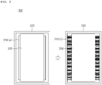
- a cylindrical type secondary battery 300 according to the present invention may be prepared by a conventional method.
- a swelling tape 310a for a secondary battery of the present invention is attached to an outer circumferential surface of an electrode assembly 330
- the electrode assembly 330, to which the swelling tape 310a is attached is accommodated in a cylindrical battery case (cylindrical can) 320.
- the swelling tape 310a attached to the outside of the electrode assembly 330 and the electrolyte are in contact with each other, since the non-aqueous organic solvent included in the electrolyte penetrates the base layer constituting the swelling tape 310a and between the polymers constituting the adhesive swelling layer or the like, the swelling tape is primarily expanded (not shown). Accordingly, a gap between the electrode assembly 330 and the battery case 320 may be filled.
- a conventional post-treatment process for example, a formation process and an aging process, may be performed to prepare a secondary battery.
- the formation process is a process of activating the battery by repeating charge and discharge after assembling the battery.
- lithium ions from a lithium metal oxide used as a positive electrode are moved and intercalated into a carbon electrode used as a negative electrode during charge, wherein, in this case, since lithium is highly reactive, it reacts with the carbon negative electrode to form compounds, such as Li 2 CO 3 , LiO, and LiOH, and thus, these compounds form a film called an SEI (Solid Electrolyte Interface) on a surface of the carbon electrode.
- SEI Solid Electrolyte Interface
- the aging process is a process in which the battery is left standing for a certain period of time to stabilize the SEI.
- the aging process is performed by exposing the secondary battery (5) subjected to the assembly process to an environment of 50°C to 70°C for 18 hours to 36 hours.
- the gap is completely filled to fix the electrode assembly while the swelling tape is secondarily expanded 310(b) by the aging process, the movement of the electrode assembly 330 may be effectively prevented.
- the secondary battery may be used in various devices.
- the secondary battery may be used in means of transportation, such as an electric bicycle, an electric vehicle, and a hybrid, but the present invention is not limited thereto and the secondary battery may be used in various devices in which a secondary battery may be used.
- thermoplastic polyurethane TPU
- a 10 um thick adhesive layer made of an acrylate-based resin was formed on one surface of the base layer, and a 15 um thick back coating layer was formed using polybutylene terephthalate on one surface of the base layer which was opposite to the surface on which the adhesive layer had been formed.
- chitosan Merck, CAS No.
- the swelling tape was attached to an outer circumferential surface of a jelly roll-shaped electrode assembly (cross-sectional diameter: 17.2 mm) including a negative electrode (negative electrode active material: artificial graphite), a separator, and a positive electrode (positive electrode active material: LCO).
- the swelling tape may be attached to cover an area of about 50% of the outer circumferential surface of the electrode assembly.
- a swelling tape and a cylindrical type secondary battery including the same were prepared in the same manner as in Example 1 except that an adhesive swelling layer was formed using sodium alginate (Merck, CAS No. 9005383 ), as a water-based self-healing binder, during the preparation of the swelling tape.
- sodium alginate Merck, CAS No. 9005383
- a cylindrical type secondary battery was prepared in the same manner as in Example 1 except that a swelling tape was prepared without forming an adhesive swelling layer on a back coating layer.
- the cylindrical type secondary batteries prepared in Examples 1 and 2 and the cylindrical type secondary battery prepared in Comparative Example 1 were charged at a 0.33 C rate to 4.2 V under a constant current/constant voltage condition at room temperature (25°C) and cut-off charged at 0.05 C, and were discharged at 0.33 C to 2.5 V.
- An SOC State Of Charge
- PNE-0506 charge/discharge equipment manufactured by PNE SOLUTION Co., Ltd., 5 V, 6 A
Abstract
Description
- This application claims priority from
Korean Patent Application Nos. 10-2020-0041322, filed on April 6, 2020 10-2021-0042758, filed on April 1, 2021 - The present invention relates to a swelling tape for a secondary battery and a cylindrical type secondary battery including the same.
- There is a need to develop technology for efficiently storing and utilizing electrical energy as personal IT devices and computer networks are developed with the development of information society and the accompanying dependency of society as a whole on the electrical energy is increased.
- Among the technologies developed for this purpose, a technology based on secondary batteries is the most suitable technology for various applications, and, among these secondary battery technologies, lithium secondary batteries having the theoretically highest energy density are in the spotlight.
- A lithium secondary battery has an operating voltage of about 3.6V, wherein, since it has a capacity of about three times that of a nickel-cadmium battery or nickel-hydrogen battery, which is frequently used as a power source of electronic equipment, and has high energy density per unit weight, there is a tendency that a degree of utilization of the lithium secondary battery increases rapidly.
- A lithium secondary battery is composed of an electrode assembly, in which a positive electrode plate coated with a positive electrode active material and a negative electrode plate coated with a negative electrode active material are disposed with a separator disposed therebetween, an electrolyte, and a case that seals and accommodates them together.
- The lithium secondary battery may be classified into a can type secondary battery and a pouch type secondary battery according to a shape of the battery case. The can type secondary battery may be further classified into a cylindrical type secondary battery and a prismatic type secondary battery according to a shape of a metal can, and may be prepared by accommodating a jelly-roll type electrode assembly, in which a positive electrode, a separator, and a negative electrode are wound, in the metal can. The pouch type secondary battery may be prepared by placing a stacked type electrode assembly, in which a plurality of positive electrodes, separators, and negative electrodes are sequentially stacked, in a pouch composed of an aluminum laminate sheet, and then sealing the pouch.
- Since the lithium secondary battery may be accommodated in machines which are frequently mobile and subjected to strong vibrations like automobiles, portability and strong vibration-resistant properties are required.
- However, with respect to the cylindrical type secondary battery, since the electrode assembly is formed in a smaller size than a cylindrical battery case (metal can) in order to accommodate the electrode assembly inside the cylindrical battery case, a gap is formed between the electrode assembly and an inner wall of the battery case. This gap causes the electrode assembly to move up and down or left and right in the battery case when vibration or impact is applied from the outside due to a fall or the like.
- The movement of the electrode assembly may increase internal resistance of the battery or may cause a power insensitive phenomenon of the secondary battery due to cutting of a tab connected between the electrode assembly and a cap assembly. In addition, since a sealing portion may be damaged or separated by applying an impact to the cap assembly coupled to an upper end opening of the secondary battery, a problem of leaking the electrolyte in the secondary battery may occur.
- In order to prevent the movement of the electrode assembly, a method of using a special tape, such as a swelling tape, has recently been applied.
- As illustrated in
FIG. 1 , if an electrolyte is injected after a swelling tape composed of anadhesive layer 110 and aswelling layer 120 is attached to an outer circumferential surface of a jelly-rolltype electrode assembly 100, in which a positive electrode, a separator, and a negative electrode are wound, and this is accommodated in a cylindrical battery case, the swelling layer expands and fills a gap existing between the electrode assembly and the battery case, and thus, the movement of the electrode assembly may be prevented. - A urethane resin, such as conventional thermoplastic polyurethane (TPU) or curable urethane, is being used as the swelling layer. However, with respect to the urethane resin, since heat resistance and fire resistance are low and it easily transmits vibration or impact to the electrode assembly, there is a disadvantage in that it is vulnerable to prevention of vibration or impact in the battery.
- Thus, there is a need to develop a new swelling tape which may effectively prevent the movement of the electrode assembly even with strong vibration or impact.
- An aspect of the present invention provides a swelling tape for a secondary battery which may effectively prevent movement of an electrode assembly in a battery.
- Another aspect of the present invention provides an electrode assembly, in which the swelling tape for a secondary battery is attached to an outer circumferential surface of the electrode assembly, and a cylindrical type secondary battery including the same.
- According to an aspect of the present invention, there is provided a swelling tape for a secondary battery which includes: a base layer and an adhesive swelling layer, wherein the adhesive swelling layer contains a water-based self-healing binder.
- The swelling tape for a secondary battery may further include at least one layer selected from an adhesive layer and a back coating layer.
- According to another aspect of the present invention, there is provided an electrode assembly in which the swelling tape for a secondary battery is attached to an outer circumferential surface of the electrode assembly.
- According to another aspect of the present invention, there is provided a cylindrical type secondary battery which includes: the electrode assembly, an electrolyte, and a cylindrical battery case accommodating the electrode assembly and the electrolyte.
- Since a swelling tape of the present invention includes an adhesive swelling layer containing a water-based self-healing binder on at least one surface of both surfaces of a base layer, it prevents unwinding of an electrode assembly in a wound state and simultaneously fills a gap between the electrode assembly and an inner wall of a battery case at a low cost, and, thus, it may effectively prevent movement of the electrode assembly. Accordingly, it may prevent a secondary battery from being damaged, ignited, and exploded due to a short circuit caused by deformation of the electrode assembly, and may also prevent electrolyte leakage due to damage to a coupling portion of a cap assembly. As a result, a secondary battery having high stability and effectively improved resistance increase rate and power insensitive phenomenon may be achieved.
- The following drawings attached to the specification illustrate preferred examples of the present invention by example, and serve to enable technical concepts of the present invention to be further understood together with detailed description of the invention given below, and therefore the present invention should not be interpreted only with matters in such drawings.
-
FIG. 1 is a schematic view of using a swelling tape on a conventional jelly-roll type electrode assembly; -
FIG. 2 is cross-sectional views of swelling tapes according to embodiments of the present invention; and -
FIG. 3 is a schematic view exemplarily illustrating a process in which the swelling tape is formed in a three-dimensional shape during a preparation process of a secondary battery according to an embodiment of the present invention. -
- 100, 330: Electrode Assembly
- 110, 201: Adhesive Layer
- 120: Swelling Layer
- 200: Swelling Tape
- 202: Base Layer
- 203: Back Coating Layer
- 220, 220(a), 220(b): Adhesive Swelling Layer Containing Water-based Self-healing Binder
- 300: Cylindrical Type Secondary Battery
- 310(a): Swelling Tape
- 310(b): Swollen Swelling Tape
- 320: Cylindrical Battery Case (Cylindrical Can)
- Hereinafter, various examples of the present invention will be described in detail with reference to the accompanying drawings in such a manner that it may easily be carried out by a person with ordinary skill in the art to which the present invention pertains. The invention may, however, be embodied in many different forms and should not be construed as being limited to the examples set forth herein.
- The expression "swelling tape" in the present specification may mean a tape which is located in a gap between two objects spaced apart from each other to fill the gap and play a role in being able to fix the two objects to each other, if necessary. In one example, in a state in which the swelling tape is attached to any one of the two objects through an adhesive layer, the swelling tape refers to a tape which may achieve a three-dimensional shape capable of filling the gap by a mutual balance between a force generated by expansion of a swelling layer and a fixing force of the adhesive layer.
- A swelling tape according to the present invention includes a base layer and an adhesive swelling layer,
wherein the adhesive swelling layer may contain a water-based self-healing binder. - The base layer is a layer in the form of a film or sheet having deformation (expansion) properties when it is in contact with a fluid like a liquid such as an electrolyte, wherein it may have a shape, such as a circular, triangular, or amorphous shape, in addition to a square shape.
- Various base layers commonly used in a conventional swelling tape may be used without limitation as the base layer, and the base layer may specifically include at least one polymer material selected from polyacrylate, thermoplastic polyurethane (TPU), polyvinyl chloride, polyethylene terephthalate, polyethylene, polypropylene, polyamide, polycarbonate, polyimide, and polystyrene, and may preferably include at least one selected from the group consisting of polyurethane and polystyrene.
- A thickness of the base layer may be selected in consideration of the three-dimensional shape to be achieved or a size of the gap to be filled, and the base layer may be specifically formed to a thickness of 10 um to 40 µm, for example, 20 um to 40 µm.
- The adhesive swelling layer of the present invention is a layer capable of filling the gap between the electrode assembly and a battery case by swelling when the electrolyte is impregnated or heat is applied, wherein it may achieve a maximum volume increase rate of 100% or more.
- A water-based self-healing binder having a glass transition temperature of -50°C to -30°C may be included as a component of the adhesive swelling layer.
- The water-based self-healing binder is a polymer having a property of swelling (expansion) by being in contact with an organic solvent contained in the electrolyte, or swelling by heat, etc., wherein, as a representative example thereof, it may include at least one compound selected from a ceramic matrix composite (CMC), alginate, and chitosan. Specifically, the water-based self-healing binder may include at least one compound selected from the group consisting of a lginate and chitosan.
- Since the alginate, as a very high molecular weight polymer, has excellent self-recovery ability, it has an excellent effect of filling the internal gap during impact when it is used in the swelling tape, and thus, it may effectively suppress the movement of the electrode assembly. In addition, since it has a strong anion component in a side chain, it is advantageous in that battery operating characteristics may be expressed even under an electric field by facilitating ion movement in the electrolyte. The alginate specifically means sodium alginate, and, in addition, ethyl lauroyl alginate or propylene glycol alginate may be used.
- The chitosan is an environmentally friendly material, wherein, since it is not only inexpensive, but also contains a large amount of hydroxy groups, it is advantageous in that binding performance is excellent. Thus, in a case in which the chitosan is used in the swelling tape, since it improves adhesiveness of the swelling tape to the electrode assembly, a secondary battery having excellent processability and reduced manufacturing costs may be prepared. Also, since the chitosan contains a nitrogen element in its structure, oxygen adsorption and decomposition ability are improved due to an oxygen reduction reaction by nitrogen atoms when the chitosan is used in the swelling tape, and thus, electrical conductivity of the secondary battery may be further improved.
- In the present invention, since high adhesiveness may be secured by using the water-based self-healing binder in the swelling tape, the use of an additional adhesive, such as an acrylic pressure sensitive adhesive (PSA), may be omitted and the gap between the electrode assembly and the battery case may be completely filled by physical properties expanding due to heat or impact. Thus, since the movement of the electrode assembly may be prevented even when vibration or impact is applied from the outside due to a fall of the battery, a stable secondary battery with improved impact resistance may be achieved.
- The adhesive swelling layer may be formed on at least one surface of both surfaces of the base layer.
- After the water-based self-healing binder is dissolved in water to prepare a binder composition, the adhesive swelling layer may be prepared by coating the base layer with the binder composition and drying the coated base layer.
- The adhesive swelling layer may be formed to a thickness of about 10% to 50%, for example, 10% to 30% of a total thickness of the base layer. In a case in which the thickness of the adhesive swelling layer satisfies the above range, the gap between the electrode assembly (jelly roll typ e) and the battery case may be filled to provide a battery that is resistant to an external impact such as vibration. That is, in the case that the thickness of the adhesive swelling layer is about 10% or more with respect to the total thickness of the base layer, a purpose of preventing the movement of the electrode assembly may be achieved by sufficiently filling the gap. In a case in which the thickness of the adhesive swelling layer is greater than about 50% of the total thickness of the base layer, since an outer diameter of the electrode assembly (J/R) is increased due to an increase in the thickness of the swelling tape, battery deformation occurs due to the expansion of the electrode assembly during a cycle operation, and thus, cell performance may be degraded.
- The adhesive swelling layer may be formed in an area ranging from 50% to 99%, for example, 70% to 95% of a total area of one surface of the base layer.
- In a case in which the area of the adhesive swelling layer satisfies the above range, cost-effective vibration resistance may be achieved. If, in a case in which the area of the adhesive swelling layer is greater than 99% of the total area of the base layer, it is not economically favorable, and, in a case in which the area of the adhesive swelling layer is less than 50%, since the area of the adhesive swelling layer is excessively small, an effect of preventing the movement of the electrode assembly may be insignificant.
- The swelling tape of the present invention may further include at least one layer selected from an adhesive layer and a back coating layer, which will be described later, if necessary, in order to further improve adhesion and swelling effects.
- The adhesive layer is a layer added to further improve adhesion of the swelling tape to the electrode assembly, wherein it may be designed to achieve an appropriate adhesive force, in other words, an appropriate peeling force, to the electrode assembly.
- The peeling force of the adhesive layer may be changed according to the size of the three-dimensional shape to be achieved or the gap to be filled, wherein a lower limit thereof may be 100 gf/25mm or more, 200 gf/25mm or more, 400 gf/25mm or more, 600 gf/25mm or more, 800 gf/25mm or more, 1,000 gf/25mm or more, 1,200 gf/25mm or more, 1,400 gf/25mm or more, 1,600 gf/25mm or more, or 1,800 gf/25mm or more. Also, an upper limit of the peeling force of the adhesive layer is not particularly limited as long as it has a general range, but may be approximately 5,000 gf/25mm or less.
- The peeling force is a peeling force measured at room temperature, and is a result measured at a peeling rate of 5 mm/sec and a peeling angle of 180°. The "room temperature" is a natural temperature that is not heated or cooled, wherein, for example, it may mean a temperature of about 10°C to about 30°C, particularly about 20°C to about 30°C, and more particularly about 25°C.
- In a case in which the peeling force of the adhesive layer is greater than the above range, it may be difficult to achieve the three-dimensional shape by excessively suppressing deformation of the swelling layer. Also, when the peeling force of the adhesive layer is less than the above range, an effect of achieving adhesiveness to be secured when the swelling tape is expanded may be insignificant.
- The adhesive layer may include an acrylic polymer having a weight-average molecular weight (Mw) of 400,000 or more. Specifically, the acrylic polymer may include a polymer in a form in which a (meth) acrylic acid ester monomer and a copolymerizable monomer having a crosslinkable functional group are polymerized. In this case, a weight ratio of each monomer is not particularly limited, and may be appropriately designed in consideration of a desired peeling force.
- An alkyl (meth)acrylate having an alkyl group having 1 to 15 carbon atoms may be used as the (meth) acrylic acid ester monomer in consideration of cohesion of the adhesive, glass transition temperature, or adhesiveness. As the monomer, one, such as methyl (meth)acrylate, ethyl (meth)acrylate, n-propyl (meth)acrylate, isopropyl (meth)acrylate, n-butyl (meth)acrylate, t-butyl (meth) acrylate, sec-butyl (meth)acrylate, pentyl (meth)acrylate, 2-ethylhexyl (meth)acrylate, 2-ethylbutyl (meth)acrylate, n-octyl (meth)acrylate, isooctyl (meth)acrylate, isononyl (meth)acrylate, lauryl (meth)acrylate, and tetradecyl (meth)acrylate, or two or more thereof may be exemplified, but the present invention is not limited thereto.
- The copolymerizable monomer having a crosslinkable functional group may include a monomer which may be copolymerized with the (meth)acrylic acid ester monomer through crosslinking and may provide a crosslinking point capable of reacting with a multifunctional crosslinking agent in a main chain of the polymer after the copolymerization. The crosslinkable functional group may be a hydroxy group, a carboxyl group, an isocyanate group, a glycidyl group or an amide group, and, in some cases, may be a photocrosslinkable functional group such as an acryloyl group or a methacryloyl group. Typical examples of the copolymerizable monomer having a crosslinkable functional group may be monomers having a hydroxy group such as 2-hydroxyethyl (meth)acrylate, 2-hydroxypropyl (meth)acrylate, 4-hydroxybutyl (meth)acrylate, 6-hydroxyhexyl (meth)acrylate, 8-hydroxyoctyl (meth)acrylate, 2-hydroxyethylene glycol (meth)acrylate, or 2-hydroxypropylene glycol (meth)acrylate; monomers having a carboxyl group such as (meth)acrylic acid, 2-(meth)acryloyloxy acetic acid, 3-(meth)acryloyloxy propyl acid, 4-(meth)acryloyloxy butyl acid, acrylic acid duplex, itaconic acid, maleic acid, and maleic anhydride; glycidyl (meth)acrylate, (meth)acrylamide, N-vinyl pyrrolidone, or N-vinyl caprolactam, but the present invention is not limited thereto. At least one of these monomers may be included in the polymer.
- The adhesive layer may be formed to a thickness of 5 µm to 20 µm, for example, 10 µm to 20 µm. If the thickness of the adhesive layer is greater than 20 um, since the outer diameter (volume) of the jelly-roll type electrode assembly is increased to reduce dispersibility of the electrolyte due to productivity problems and a decrease in space in the cell, safety and overall performance of the secondary battery may be degraded.
- The adhesive layer may be formed i) between the base layer and the adhesive swelling layer, or may be formed ii) on at least one surface selected from the base layer and the adhesive swelling layer in order to secure more improved adhesiveness.
- The back coating layer is a layer added to further improve the gap filling effect, wherein it may be formed of a thermosetting adhesive material which swells while an orientation is partially reduced by contact and impregnation with the electrolyte, or exhibits adhesiveness when heat is applied in a predetermined amount or more.
- Specifically, the back coating layer may include a single material selected from the group consisting of polyimide, polybuthylene terephthalate (PBT), polyamideimide (PAI), perfluoroalkoxy (PFA), polysulfone (PSF), polyarylsulfone (PAS), polytetrafluoroethylene (PTFE), fluorinated ethylene propylene (FEP), ethylenetetrafluoroethylene (ETFE), and polyethylene naphthalene (PEN), or a mixture of two or more thereof.
- With respect to the back coating layer, since adhesiveness is expressed by heat, the adhesiveness is not expressed when the electrode assembly, to which the swelling tape using the back coating layer is attached, is inserted into a battery case, and thus, the electrode assembly may be easily accommodated.
- Thereafter, when an electrolyte is injected into the battery case, the gap may be filled while the back coating layer expands. Furthermore, if a heat application process is performed in a preparation process of the secondary battery, since the adhesiveness of the back coating layer is expressed, the movement of the electrode assembly may be more effectively improved while the adhesion of the swelling tape is improved. In this case, the heat application process may be an aging process performed during a conventional secondary battery preparation process, or a separate additional process may be added.
- The back coating layer may be formed i) between the base layer and the adhesive swelling layer, or may be formed ii) on the adhesive swelling layer in order to secure more improved adhesiveness.
- It is desirable that the swelling tape of the present invention is formed to a total thickness of 200 um or less, particularly 20 um to 200 µm, and more particularly 20 um to 150 µm, for example, 40 um to 120 um. If, in a case in which the thickness of the swelling tape is less than 20 µm, since it is difficult to secure a sufficient thickness even by the heat or the contact with the electrolyte, it may be difficult to secure the effect of preventing the movement of the electrode assembly. Also, in a case in which the thickness of the swelling tape is greater than 200 µm, since the accommodation of the electrode assembly in the battery case is not only not easy, but a space between the battery case and the electrode assembly is also reduced to reduce the dispersibility of the electrolyte and reduce an electrolyte injection amount by that much, there is a disadvantage in that it is difficult to secure capacity of the secondary battery.
- The swelling tape of the present invention may be prepared in various structures including the base layer and the adhesive swelling layer as well as selectively the adhesive layer and/or the back coating layer. Specifically,
FIG. 2 schematically illustrates examples of various configurations of the swelling tapes according to embodiments of the present invention, respectively. - That is, as illustrated in
FIG. 2a , a swellingtape 200 of the present invention according to an embodiment may include abase layer 202 and anadhesive swelling layer 220 formed on one surface of the base layer. - Also, as illustrated in
FIG. 2b , a swellingtape 200 of the present invention according to an embodiment may include adhesive swelling layers 220 (a) and 220 (b) formed on both surfaces of thebase layer 202. - Furthermore, as illustrated in
FIG. 2c , a swellingtape 200 of the present invention according to an embodiment may include anadhesive layer 201, thebase layer 202, aback coating layer 203, and theadhesive swelling layer 220, wherein theback coating layer 203 may be formed between thebase layer 202 and theadhesive swelling layer 220. - Next, an electrode assembly, in which the swelling tape for a secondary battery according to the present invention is attached to an outer circumferential surface thereof, will be described.
- Since the configuration of the swelling tape for a secondary battery has been described above, a description thereof will be omitted, and, hereinafter, a shape of the swelling tape attached to the outer circumferential surface of the electrode assembly will be described.
- The swelling tape of the present invention may be disposed on the outer circumferential surface of the wound electrode assembly to maintain a shape of the electrode assembly, and may be simultaneously disposed between the outer circumferential surface of the electrode assembly and an inner surface of the battery case to prevent the movement of the electrode assembly in the battery case.
- Specifically, the swelling tape of the present invention may be attached to surround an entire height of the outer circumferential surface of the electrode assembly, and, more preferably, may be attached to a portion excluding portions of an upper end portion and a lower end portion of the outer circumferential surface of the electrode assembly.
- The upper end portion of the electrode assembly is a portion that acts as a space through which the electrolyte may permeate between the battery case and the electrode assembly, and the lower end portion is a portion where the electrolyte injected into a bottom of the battery case is in contact with the electrode assembly. Thus, in consideration of impregnability of the electrolyte impregnated in the electrode assembly, it is desirable that the swelling tape is not attached to the portions of the upper end portion and the lower end portion of the electrode assembly.
- In addition, the swelling tape may be wound and attached to cover an entire length of the outer circumferential surface of the electrode assembly, and, in order to prevent the movement of the electrode assembly, it is desirable to attach the swelling tape by wrapping the swelling tape one or more times within a range covering the entire length of the outer circumferential surface of the electrode assembly.
- Length and thickness of the swelling tape of the present invention are not necessarily limited because they may be variably deformed according to specifications of the battery, but, for example, a minor axis length (width) of the swelling tape may be the same as a height (length) of the electrode assembly to be described later, or may be smaller or larger by about 1% to 10% or less, wherein it is most desirable that it is smaller by about 10% or less. If, in a case in which the minor axis length (width) of the swelling tape is smaller by 10% or more based on the height (length) of the electrode assembly to be described later, there is a disadvantage in that the effect of preventing the movement of the electrode assembly may not be sufficiently achieved. Also, in a case in which the minor axis length (width) of the swelling tape is larger by 1% or more based on the height (length) of the electrode assembly to be described later, since the swelling tape is attached to the portions of the upper end portion and the lower end portion of the electrode assembly, there is a disadvantage in that the impregnability of the electrolyte is reduced.
- Next, the electrode assembly will be described.
- The electrode assembly according to the present invention includes a positive electrode, a negative electrode, and a separator (not shown) disposed between the positive electrode and the negative electrode to electrically insulate them, and, in this case, the positive electrode, the separator, and the negative electrode may be wound together and formed in a jelly-roll shape.
- The positive electrode constituting the electrode assembly according to the present invention may include a positive electrode active material layer including a positive electrode active material, and, if necessary, the positive electrode active material layer may further include a conductive agent and/or a binder.
- The positive electrode active material may include a lithium metal oxide including lithium and at least one metal such as cobalt, manganese, nickel, or aluminum. Specifically, the lithium metal oxide may include lithium-manganese-based oxide (e.g., LiMnO2, LiMn2O4, etc.), lithium-cobalt-based oxide (e.g., LiCoO2, etc.), lithium-nickel-based oxide (e.g., LiNiO2, etc.), lithium-nickel-manganese-based oxide (e.g., LiNi1-YMnYO2 (where 0<Y<1), LiMn2-ZNizO4 (where 0<Z<2)), lithium-nickel-cobalt-based oxide (e.g., LiNi1-Y1CoY1O2 (where 0<Y1<1)), lithium-manganese-cobalt-based oxide (e.g., LiCo1-Y2MnY2O2 (where 0<Y2<1), LiMn2-Z1Coz1O4 (where 0<Z1<2)), lithium-nickel-manganese-cobalt-based oxide (e.g., Li(NipCoqMnr1)O2 (where 0<p<1, 0<q<1, 0<r1<1, and p+q+r1=1) or Li(Nip1Coq1Mnr2)O4 (where 0<p1<2, 0<q1<2, 0<r2<2, and p1+q1+r2=2), or lithium-nickel-cobalt-transition metal (M) oxide (e.g., Li(Nip2Coq2Mnr3MS2)O2 (where M is selected from the group consisting of aluminum (Al), iron (Fe), vanadium (V), chromium (Cr), titanium (Ti), tantalum (Ta), magnesium (Mg), and molybdenum (Mo), and p2, q2, r3, and s2 are atomic fractions of each independent elements, wherein 0<p2<1, 0<q2<1, 0<r3<1, 0<S2<1, and p2+q2+r3+S2=1), and any one thereof or a mixture of two or more thereof may be included.
- The positive electrode active material may be included in an amount of 90 wt% to 99 wt%, for example, 93 wt% to 98 wt% based on a total weight of solid content in the positive electrode active material layer.
- The conductive agent is not particularly limited as long as it has conductivity without causing adverse chemical changes in the battery, and, for example, a conductive material, such as: carbon powder such as carbon black, acetylene black, Ketjen black, channel black, furnace black, lamp black, or thermal black; graphite powder such as natural graphite with a well-developed crystal structure, artificial graphite, or graphite; conductive fibers such as carbon fibers or metal fibers; metal powder such as fluorocarbon powder, aluminum powder, and nickel powder; conductive whiskers such as zinc oxide whiskers and potassium titanate whiskers; conductive metal oxide such as titanium oxide; or polyphenylene derivatives, may be used.
- The conductive agent is commonly added in an amount of 1 wt% to 30 wt% based on the total weight of the solid content in the positive electrode active material layer.
- The binder is a component that improves the adhesion between the positive electrode active material particles and the adhesion between the positive electrode active material and the current collector, wherein the binder is commonly added in an amount of 1 wt% to 30 wt% based on the total weight of the solid content in the positive electrode active material layer. Examples of the binder may be a fluorine resin-based binder including polyvinylidene fluoride (PVDF) or polytetrafluoroethylene (PTFE); a rubber-based binder including a styrene butadiene rubber (SBR), an acrylonitrile-butadiene rubber, or a styrene-isoprene rubber; a cellulose-based binder including carboxymethylcellulose (CMC), starch, hydroxypropylcellulose, or regenerated cellulose; a polyalcohol-based binder including polyvinyl alcohol; a polyolefin-based binder including polyethylene or polypropylene; a polyimide-based binder; a polyester-based binder; and a silane-based binder.
- The positive electrode of the present invention may be prepared by a method of preparing a positive electrode which is known in the art. For example, the positive electrode may be prepared by a method in which a positive electrode current collector is coated with a positive electrode slurry, which is prepared by dissolving or dispersing the positive electrode active material, the binder, and/or the conductive agent in a solvent, dried, and then rolled to form a positive electrode active material layer, or a method in which the positive electrode active material is cast on a separate support and a film separated from the support is then laminated on the positive electrode current collector.
- The positive electrode current collector is not particularly limited as long as it has conductivity without causing adverse chemical changes in the battery, and, for example, stainless steel, aluminum, nickel, titanium, fired carbon, or aluminum or stainless steel that is surface-treated with one of carbon, nickel, titanium, silver, or the like may be used. Microscopic irregularities may be formed on a surface of the positive electrode current collector to enhance a binding force with the positive electrode active material described above.
- The solvent may include an organic solvent, such as N-methyl-2-pyrrolidone (NMP), and may be used in an amount such that desirable viscosity is obtained when the positive electrode active material as well as selectively the binder and the conductive agent are included. For example, the solvent may be included in an amount such that a concentration of the solid content in the active material slurry including the positive electrode active material as well as selectively the binder and the conductive agent is in a range of 10 wt% to 70 wt%, for example, 20 wt% to 60 wt%.
- Next, the negative electrode constituting the electrode assembly according to the present invention includes a negative electrode active material layer including a negative electrode active material, and the negative electrode active material layer may further include a conductive agent and/or a binder, if necessary.
- The negative electrode active material may include at least one negative electrode active material selected from the group consisting of a carbonaceous material such as natural graphite and artificial graphite; lithium-containing titanium composite oxide (LTO); metals (Me) such as silicon (Si), tin (Sn), lithium (Li), zinc (Zn), Mg, cadmium (Cd), cerium (Ce), nickel (Ni), or Fe; alloys composed of the metals (Me); oxides of the metals; and composites of the metals and carbon.
- The negative electrode active material may be included in an amount of 80 wt% to 99 wt% based on a total weight of solid content in the negative electrode active material layer.
- The conductive material and the binder, which are the same as or different from those used in the preparation of the positive electrode, may be used. In this case, the conductive agent may be added in an amount of 1 wt% to 20 wt% based on the total weight of the solid content in the negative electrode active material layer, and the binder may be added in an amount of 1 wt% to 30 wt% based on the total weight of the solid content in the negative electrode active material layer.
- The negative electrode may be prepared by a method of preparing a negative electrode which is known in the art. For example, the negative electrode may be prepared by a method in which a negative electrode current collector is coated with a negative electrode active material slurry, which is prepared by dissolving or dispersing the negative electrode active material as well as selectively the binder and the conductive agent in a solvent, rolled and dried to form a negative electrode active material layer, or may be prepared by casting the negative electrode active material on a separate support and then laminating a film separated from the support on the negative electrode current collector.
- The negative electrode current collector is not particularly limited as long as it has high conductivity without causing adverse chemical changes in the battery, and, for example, copper, stainless steel, aluminum, nickel, titanium, fired carbon, copper or stainless steel that is surface-treated with one of carbon, nickel, titanium, silver, or the like, and an aluminum-cadmium alloy may be used. Also, similar to the positive electrode current collector, microscopic irregularities may be formed on a surface of the current collector to enhance a binding force with the negative electrode active material, and the negative electrode current collector may be used in various shapes such as that of a film, a sheet, a foil, a net, a porous body, a foam body, a nonwoven fabric body, and the like.
- The solvent may include water or an organic solvent, such as NMP and alcohol, and may be used in an amount such that desirable viscosity is obtained when the negative electrode active material as well as selectively the binder and the conductive agent are included. For example, the solvent may be included in an amount such that a concentration of the solid content in the negative electrode active material slurry including the negative electrode active material as well as selectively the binder and the conductive agent is in a range of 50 wt% to 75 wt%, for example, 50 wt% to 65 wt%.
- A typical porous polymer film used as a typical separator, for example, a porous polymer film prepared from a polyolefin-based polymer, such as an ethylene homopolymer, a propylene homopolymer, an ethylene-butene copolymer, an ethylene-hexene copolymer, and an ethylene-methacrylate copolymer, may be used alone or in a lamination therewith as the separator included in the electrode assembly according to the present invention, and a polyolefin-based porous polymer film coated with inorganic particles (e.g.: Al2O3) or a typical porous nonwoven fabric, for example, a nonwoven fabric formed of high melting point glass fibers or polyethylene terephthalate fibers may be used, but the present invention is not limited thereto.
- Next, a lithium secondary battery according to the present invention will be described.
- The lithium secondary battery according to the present invention provides a cylindrical type secondary battery which includes an electrode assembly having a swelling tape for a secondary battery attached to an outer circumferential surface thereof, an electrolyte, and a cylindrical battery case accommodating the electrode assembly and the electrolyte. Since the electrode assembly having the swelling tape for a secondary battery attached to the outer circumferential surface thereof has been described above, a description thereof will be omitted, and other components will be described below.
- The cylindrical type secondary battery according to the present invention includes an electrolyte so that lithium ions generated by an electrochemical reaction in an electrode may move during charge and discharge.
- As the electrolyte, a liquid electrolyte containing a non-aqueous organic solvent in which a lithium salt is dissolved, or a gel polymer electrolyte containing a polymer resin capable of being gelated in the non-aqueous organic solvent may be used without limitation.
- Various lithium salts typically used in an electrolyte for a lithium secondary battery may be used as the lithium salt without limitation. For example, the lithium salt may include Li+ as a cation, and may include at least one selected from the group consisting of F-, Cl-, Br-, I-, NO3 -, N(CN)2 -, BF4 -, ClO4 -, AlO4 -, AlCl4 -, PF6 -, SbF6 -, AsF6 -, B10Cl10 -, BF2C2O4 -, BC4O8 -, PF4C2O4 -, PF2C4O8 -, (CF3)2PF4 -, (CF3)3PF3 -, (CF3)4PF2 -, (CF3)5PF-, (CF3)6P-, CF3SO3 -, C4F9SO3 -, CF3CF2SO3 -, (CF3SO2)2N-, (FSO2)2N-, CF3CF2(CF3)2CO-, (CF3SO2)2CH-, CH3SO3 -, CF3(CF2)7SO3 -, CF3CO2 -, CH3CO2 -, SCN-, and (CF3CF2SO2)2N- as an anion.
- Specifically, the lithium salt may include at least one selected from the group consisting of LiCl, LiBr, LiI, LiBF4, LiClO4, LiAlO4, LiAlCl4, LiPF6, LiSbF6, LiAsF6, LiB10Cl10, LiBOB (LiB(C2O4)2), LiCF3SO3, LiTFSI (LiN(SO2CF3)2), LiFSI (LiN(SO2F)2), LiCH3SO3, LiCF3CO2, LiCH3CO2, and LiBETI (LiN(SO2CF2CF3)2). Specifically, the lithium salt may include a single material selected from the group consisting of LiBF4, LiClO4, LiPF6, LiBOB (LiB(C2O4)2), LiCF3SO3, LiTFSI (LiN(SO2CF3)2), LiFSI (LiN(SO2F)2), and LiBETI (LiN(SO2CF2CF3)2), or a mixture of two or more thereof.
- The lithium salt may be appropriately changed in a normally usable range, but may be included in a concentration of 0.8 M to 4.0 M, for example, 1.0 M to 3.0 M in the electrolyte to obtain an optimum effect of forming a film for preventing corrosion of a surface of an electrode.
- The non-aqueous organic solvent may include a cyclic carbonate-based organic solvent, a linear carbonate-based organic solvent, or a mixed organic solvent thereof.
- The cyclic carbonate-based organic solvent is an organic solvent which may well dissociate a lithium salt in an electrolyte due to high permittivity as a highly viscous organic solvent, wherein specific examples of the cyclic carbonate-based organic solvent may be at least one organic solvent selected from the group consisting of ethylene carbonate (EC), propylene carbonate (PC), 1,2-butylene carbonate, 2,3-butylene carbonate, 1,2-pentylene carbonate, 2,3-pentylene carbonate, and vinylene carbonate, and, among them, the cyclic carbonate-based organic solvent may include ethylene carbonate.
- Also, the linear carbonate-based organic solvent is an organic solvent having low viscosity and low permittivity, wherein typical examples of the linear carbonate-based organic solvent may be at least one organic solvent selected from the group consisting of dimethyl carbonate (DMC), diethyl carbonate (DEC), dipropyl carbonate, ethyl methyl carbonate (EMC), methylpropyl carbonate, and ethylpropyl carbonate, and the linear carbonate-based organic solvent may specifically include at least one selected from dimethyl carbonate, ethyl methyl carbonate, and dipropyl carbonate.
- The electrolyte may easily penetrate between polymers constituting the swelling tape for a secondary battery of the present invention to expand them.
- The cylindrical type secondary battery according to the present invention may include a cylindrical battery case accommodating the electrode assembly and a cap assembly for sealing the cylindrical battery case on an upper portion of the cylindrical battery case.
- The cap assembly may further include an insulating gasket, and may allow a current generated in the electrode assembly to flow to an external device.
- An inner surface of the cylindrical battery case of the present invention may be formed of a material having relatively good affinity with the electrolyte, such as aluminum (Al) or iron (Fe).
- A cylindrical type
secondary battery 300 according to the present invention may be prepared by a conventional method. - As illustrated in
FIG. 3 , after a swelling tape 310a for a secondary battery of the present invention is attached to an outer circumferential surface of anelectrode assembly 330, theelectrode assembly 330, to which the swelling tape 310a is attached, is accommodated in a cylindrical battery case (cylindrical can) 320. - Then, the above-described electrolyte (not shown) is injected into the
cylindrical battery case 320. - As a result, while the swelling tape 310a attached to the outside of the
electrode assembly 330 and the electrolyte are in contact with each other, since the non-aqueous organic solvent included in the electrolyte penetrates the base layer constituting the swelling tape 310a and between the polymers constituting the adhesive swelling layer or the like, the swelling tape is primarily expanded (not shown). Accordingly, a gap between theelectrode assembly 330 and thebattery case 320 may be filled. - Then, after a secondary battery is assembled by a known method of fixing the cap assembly to an opening of the battery case, a conventional post-treatment process, for example, a formation process and an aging process, may be performed to prepare a secondary battery.
- In this case, the formation process is a process of activating the battery by repeating charge and discharge after assembling the battery. In the formation process, lithium ions from a lithium metal oxide used as a positive electrode are moved and intercalated into a carbon electrode used as a negative electrode during charge, wherein, in this case, since lithium is highly reactive, it reacts with the carbon negative electrode to form compounds, such as Li2CO3, LiO, and LiOH, and thus, these compounds form a film called an SEI (Solid Electrolyte Interface) on a surface of the carbon electrode.
- Also, the aging process is a process in which the battery is left standing for a certain period of time to stabilize the SEI. In general, the aging process is performed by exposing the secondary battery (5) subjected to the assembly process to an environment of 50°C to 70°C for 18 hours to 36 hours.
- Since the gap is completely filled to fix the electrode assembly while the swelling tape is secondarily expanded 310(b) by the aging process, the movement of the
electrode assembly 330 may be effectively prevented. - The secondary battery may be used in various devices. The secondary battery may be used in means of transportation, such as an electric bicycle, an electric vehicle, and a hybrid, but the present invention is not limited thereto and the secondary battery may be used in various devices in which a secondary battery may be used.
- Although the exemplary embodiments of the present invention have been described in detail, the scope of the present invention is not limited thereto but various modifications and improvements made by those skilled in the art using the basic concept of the present invention defined in the claims also fall within the scope of the present invention.
- An about 30 um thick cast film formed of thermoplastic polyurethane (TPU) was prepared as a base layer. A 10 um thick adhesive layer made of an acrylate-based resin was formed on one surface of the base layer, and a 15 um thick back coating layer was formed using polybutylene terephthalate on one surface of the base layer which was opposite to the surface on which the adhesive layer had been formed. Then, as a water-based self-healing binder, chitosan (Merck, CAS No. 9012764, product name: 419419) was dissolved in water to prepare a binder composition, and one surface of the back coating layer was coated with the binder composition to a thickness of 7 um (about 23% with respect to the base layer) and dried to prepare a swelling tape including an adhesive swelling layer (see
FIG. 2(c) ). - The swelling tape was attached to an outer circumferential surface of a jelly roll-shaped electrode assembly (cross-sectional diameter: 17.2 mm) including a negative electrode (negative electrode active material: artificial graphite), a separator, and a positive electrode (positive electrode active material: LCO). The swelling tape may be attached to cover an area of about 50% of the outer circumferential surface of the electrode assembly.
- Then, after the assembly was inserted into a cylindrical battery case (cross-sectional diameter: 17.5 mm), an electrolyte (1.0 M LiPF6/EC:EMC=30:70 volume ratio) was injected, and an upper portion of the cylindrical battery case was sealed with a cap assembly to complete a cylindrical type secondary battery.
- A swelling tape and a cylindrical type secondary battery including the same were prepared in the same manner as in Example 1 except that an adhesive swelling layer was formed using sodium alginate (Merck, CAS No. 9005383), as a water-based self-healing binder, during the preparation of the swelling tape.
- A cylindrical type secondary battery was prepared in the same manner as in Example 1 except that a swelling tape was prepared without forming an adhesive swelling layer on a back coating layer.
- The cylindrical type secondary batteries prepared in Examples 1 and 2 and the cylindrical type secondary battery prepared in Comparative Example 1 were charged at a 0.33 C rate to 4.2 V under a constant current/constant voltage condition at room temperature (25°C) and cut-off charged at 0.05 C, and were discharged at 0.33 C to 2.5 V. An SOC (State Of Charge) was set to 30% based on discharge capacity after each of the above charging and discharging was performed once, and direct current internal resistance was measured (measured using PNE-0506 charge/discharge equipment (manufacturer: PNE SOLUTION Co., Ltd., 5 V, 6 A)) by a voltage drop obtained when a discharge pulse was applied at 5 A (2.5 C) for 10 seconds. The measured resistance was set as initial resistance.
- Then, after the cylindrical type secondary batteries prepared in Examples 1 and 2 and the cylindrical type secondary battery prepared in Comparative Example 1 were randomly dropped three times from a height of 1.0 m to a concrete ground, respectively, a degree of appearance damage was evaluated. The results thereof are listed in Table 1 below.
[Table 1] Example 1 Example 2 Comparative Example 1 Degree of appearance damage by impact 4 5 3 - In Table 1, a degree of the most severe appearance damage (standard) was set to 1, and a degree of the lowest appearance damage was indicated as 5.
- Referring to Table 1, with respect to the cylindrical type secondary batteries including the adhesive swelling layer formed of the water-based self-healing binder which were prepared in Examples 1 and 2 of the present invention, it may be confirmed that degrees of appearance damage by impact were lower than that of the cylindrical type secondary battery prepared in Comparative Example 1.
- After the cylindrical type secondary batteries prepared in Examples 1 and 2 and the cylindrical type secondary battery prepared in Comparative Example 1, in which the impact resistance evaluation test of Experimental Example 1 had been completed, were charged at a current density of 3 A to 4.2 V under a constant current/constant voltage condition at room temperature (25°C) and cut-off charged at 50 mA and were discharged at a current density of 0.4 A to 2.5 V under a constant current (CC) condition, an SOC (State Of Charge) was set to 30% based on discharge capacity (DCH) after resting for 30 minutes. Thereafter, direct current internal resistance was measured (measured using PNE-0506 charge/discharge equipment (manufacturer: PNE SOLUTION Co., Ltd., 5 V, 6 A)) by a voltage drop obtained when a discharge pulse was applied three times at 0.1 A for 10 seconds and at 10 A for 1 second at room temperature (25°C). A resistance increase rate (%) was calculated by comparing the measured direct current internal resistance with the initial resistance (0%) measured in Experimental Example 1, and the results thereof are presented in Table 2 below.
[Table 2] Example 1 Example 2 Comparative Example 1 Resistance increase rate (%) 16 10 20 - Referring to Table 2, with respect to the cylindrical type secondary batteries including the adhesive swelling layer formed of the water-based self-healing binder which were prepared in Examples 1 and 2 of the present invention, it may be confirmed that resistance increase rates were lower than that of the cylindrical type secondary battery of Comparative Example 1.
- Voltage increase rates for the cylindrical type secondary batteries prepared in Examples 1 and 2 and the cylindrical type secondary battery prepared in Comparative Example 1, in which the impact resistance evaluation test of Experimental Example 1 had been completed, were measured using a voltage/resistance meter (Hioki RM 3548), and, the results thereof are presented in Table 3 below.
[Table 3] Example 1 Example 2 Comparative Example 1 Voltage increase rate (%) 2.0 1.8 2.4 - Referring to Table 3, with respect to the cylindrical type secondary batteries including the adhesive swelling layer formed of the water-based self-healing binder which were prepared in Examples 1 and 2 of the present invention, it may be confirmed that voltage increase rates were lower than that of the cylindrical type secondary battery of Comparative Example 1.
Claims (11)
- A swelling tape for a secondary battery, the swelling tape comprising a base layer and an adhesive swelling layer,
wherein the adhesive swelling layer comprises a water-based self-healing binder. - The swelling tape for a secondary battery of claim 1, wherein the adhesive swelling layer is formed on at least one surface of both surfaces of the base layer.
- The swelling tape for a secondary battery of claim 1, wherein the water-based self-healing binder comprises at least one compound selected from a ceramic matrix composite (CMC), alginate, and chitosan.
- The swelling tape for a secondary battery of claim 1, wherein the water-based self-healing binder comprises at least one compound selected from the group consisting of alginate and chitosan.
- The swelling tape for a secondary battery of claim 1, wherein a thickness of the adhesive swelling layer is in a range of 10% to 50% of a total thickness of the base layer.
- The swelling tape for a secondary battery of claim 1, further comprising at least one layer selected from an adhesive layer and a back coating layer.
- The swelling tape for a secondary battery of claim 6, wherein the adhesive layer and the back coating layer are formed on one surface and the other surface of the base layer, respectively.
- The swelling tape for a secondary battery of claim 6, wherein the adhesive layer is formed i) between the base layer and the adhesive swelling layer, or ii) on at least one surface selected from the base layer and the adhesive swelling layer.
- The swelling tape for a secondary battery of claim 6, wherein the back coating layer is formed i) between the base layer and the adhesive swelling layer, or ii) on the adhesive swelling layer.
- An electrode assembly in which the swelling tape for a secondary battery of claim 1 is attached to an outer circumferential surface of the electrode assembly.
- A cylindrical type secondary battery comprising:the electrode assembly of claim 10,an electrolyte, anda cylindrical battery case accommodating the electrode assembly and the electrolyte.
Applications Claiming Priority (3)
| Application Number | Priority Date | Filing Date | Title |
|---|---|---|---|
| KR20200041322 | 2020-04-06 | ||
| KR1020210042758A KR20210124063A (en) | 2020-04-06 | 2021-04-01 | Swelling tape for secondary battery and cylindrical secondary battery comprising the same |
| PCT/KR2021/004147 WO2021206381A1 (en) | 2020-04-06 | 2021-04-02 | Swelling tape for secondary battery and cylindrical secondary battery comprising same |
Publications (2)
| Publication Number | Publication Date |
|---|---|
| EP4134408A1 true EP4134408A1 (en) | 2023-02-15 |
| EP4134408A4 EP4134408A4 (en) | 2023-08-30 |
Family
ID=78023608
Family Applications (1)
| Application Number | Title | Priority Date | Filing Date |
|---|---|---|---|
| EP21785670.7A Pending EP4134408A4 (en) | 2020-04-06 | 2021-04-02 | Swelling tape for secondary battery and cylindrical secondary battery comprising same |
Country Status (5)
| Country | Link |
|---|---|
| US (1) | US20220376289A1 (en) |
| EP (1) | EP4134408A4 (en) |
| JP (1) | JP2023508012A (en) |
| CN (1) | CN114901766B (en) |
| WO (1) | WO2021206381A1 (en) |
Families Citing this family (2)
| Publication number | Priority date | Publication date | Assignee | Title |
|---|---|---|---|---|
| CN114614108A (en) * | 2022-03-28 | 2022-06-10 | 宁德新能源科技有限公司 | Electrochemical device and electronic device |
| CN114410239B (en) * | 2022-03-28 | 2022-07-26 | 宁德新能源科技有限公司 | Bonding member for electrochemical device, electrochemical device and electronic device |
Family Cites Families (9)
| Publication number | Priority date | Publication date | Assignee | Title |
|---|---|---|---|---|
| JP4365791B2 (en) * | 2005-01-19 | 2009-11-18 | 協立化学産業株式会社 | Non-aqueous electrolyte battery adhesive and non-aqueous electrolyte battery using the same |
| CN103597635B (en) * | 2011-04-05 | 2016-10-19 | Lg化学株式会社 | Fill the swelling adhesive tape in gap |
| JP6488592B2 (en) * | 2014-08-27 | 2019-03-27 | 日本ゼオン株式会社 | Slurry composition for negative electrode of lithium ion secondary battery, negative electrode for lithium ion secondary battery and lithium ion secondary battery |
| KR102140689B1 (en) * | 2016-06-08 | 2020-08-04 | 주식회사 엘지화학 | Lithium secondary battery |
| KR101873472B1 (en) * | 2017-05-17 | 2018-07-02 | 주식회사 애니원 | Adhesive swelling tape for sealing battery, method for manufacturing the same and lithium secondary battery having the same |
| KR102561111B1 (en) * | 2017-12-05 | 2023-07-28 | 삼성에스디아이 주식회사 | Secondary battery |
| KR102331161B1 (en) * | 2018-02-19 | 2021-11-26 | 주식회사 엘지에너지솔루션 | Secondary Battery having Heat Absorbing Additive |
| KR20200017291A (en) * | 2018-08-08 | 2020-02-18 | 삼성전자주식회사 | Battery and electronic device including the same |
| CN109585714A (en) * | 2019-01-22 | 2019-04-05 | 广州市云通磁电股份有限公司 | A kind of cylindrical lithium-ion power battery shell and its manufacturing method |
-
2021
- 2021-04-02 WO PCT/KR2021/004147 patent/WO2021206381A1/en unknown
- 2021-04-02 EP EP21785670.7A patent/EP4134408A4/en active Pending
- 2021-04-02 JP JP2022537896A patent/JP2023508012A/en active Pending
- 2021-04-02 US US17/789,339 patent/US20220376289A1/en active Pending
- 2021-04-02 CN CN202180007474.7A patent/CN114901766B/en active Active
Also Published As
| Publication number | Publication date |
|---|---|
| JP2023508012A (en) | 2023-02-28 |
| CN114901766A (en) | 2022-08-12 |
| WO2021206381A1 (en) | 2021-10-14 |
| US20220376289A1 (en) | 2022-11-24 |
| EP4134408A4 (en) | 2023-08-30 |
| CN114901766B (en) | 2024-01-09 |
Similar Documents
| Publication | Publication Date | Title |
|---|---|---|
| EP2178137B1 (en) | Lithium-Ion secondary battery | |
| US8795884B2 (en) | Nonaqueous secondary battery and electronic device | |
| US8828605B2 (en) | Lithium-ion secondary battery | |
| KR100399788B1 (en) | Polymeric sol electrolyte and lithium battery employing the same | |
| EP2238643B1 (en) | Pouch-type lithium secondary battery | |
| EP2070150B1 (en) | Non-aqueous electrolyte solution and electrochemical device comprising the same | |
| US8574760B2 (en) | Safety-enhanced electrochemical device including electrode containing binder and wax | |
| EP2706605B1 (en) | Electrode assembly having a novel structure and secondary battery using same | |
| KR20000076975A (en) | Secondary battery | |
| KR100691113B1 (en) | Functional electrolyte additives and electrochemical device comprising the same | |
| EP1381105B1 (en) | Lithium polymer secondary cell | |
| KR20140147412A (en) | Case for electrochemical device containing volume expansibile material and electrochemical device comprising the same | |
| EP4134408A1 (en) | Swelling tape for secondary battery and cylindrical secondary battery comprising same | |
| EP3301749B1 (en) | Method for producing secondary battery | |
| KR20040108217A (en) | Organic electrolytic solution and lithium battery employing the same | |
| JP5187720B2 (en) | Lithium ion polymer battery | |
| JP3885227B2 (en) | Non-aqueous secondary battery | |
| JP2008282735A (en) | Nonaqueous electrolyte secondary battery and manufacturing method therefor | |
| KR20210124063A (en) | Swelling tape for secondary battery and cylindrical secondary battery comprising the same | |
| JP2007280947A (en) | Nonaqueous electrolyte battery and its manufacturing method | |
| US20220223915A1 (en) | Electrolyte, electrochemical device including same, and electronic device | |
| WO2012014255A1 (en) | Lithium ion secondary battery | |
| JP2003272706A (en) | Voltage control method for nonaqueous electrolyte secondary battery | |
| CN112771705B (en) | Electrolyte for lithium ion secondary battery and lithium ion secondary battery | |
| WO2020080245A1 (en) | Negative electrode for lithium ion secondary battery, and lithium ion secondary battery |
Legal Events
| Date | Code | Title | Description |
|---|---|---|---|
| STAA | Information on the status of an ep patent application or granted ep patent |
Free format text: STATUS: THE INTERNATIONAL PUBLICATION HAS BEEN MADE |
|
| PUAI | Public reference made under article 153(3) epc to a published international application that has entered the european phase |
Free format text: ORIGINAL CODE: 0009012 |
|
| STAA | Information on the status of an ep patent application or granted ep patent |
Free format text: STATUS: REQUEST FOR EXAMINATION WAS MADE |
|
| 17P | Request for examination filed |
Effective date: 20220615 |
|
| AK | Designated contracting states |
Kind code of ref document: A1 Designated state(s): AL AT BE BG CH CY CZ DE DK EE ES FI FR GB GR HR HU IE IS IT LI LT LU LV MC MK MT NL NO PL PT RO RS SE SI SK SM TR |
|
| DAV | Request for validation of the european patent (deleted) | ||
| DAX | Request for extension of the european patent (deleted) | ||
| A4 | Supplementary search report drawn up and despatched |
Effective date: 20230801 |
|
| RIC1 | Information provided on ipc code assigned before grant |
Ipc: H01M 50/489 20210101ALI20230726BHEP Ipc: H01M 50/48 20210101ALI20230726BHEP Ipc: H01M 50/474 20210101ALI20230726BHEP Ipc: H01M 50/107 20210101ALI20230726BHEP Ipc: H01M 10/04 20060101ALI20230726BHEP Ipc: C09J 1/00 20060101ALI20230726BHEP Ipc: C09J 7/30 20180101ALI20230726BHEP Ipc: C09J 7/20 20180101AFI20230726BHEP |