EP4134038A1 - Inventory systems and methods for detecting and counting potentially retained surgical items - Google Patents
Inventory systems and methods for detecting and counting potentially retained surgical items Download PDFInfo
- Publication number
- EP4134038A1 EP4134038A1 EP22189319.1A EP22189319A EP4134038A1 EP 4134038 A1 EP4134038 A1 EP 4134038A1 EP 22189319 A EP22189319 A EP 22189319A EP 4134038 A1 EP4134038 A1 EP 4134038A1
- Authority
- EP
- European Patent Office
- Prior art keywords
- tag
- dual detection
- return signal
- frequency
- beacon
- Prior art date
- Legal status (The legal status is an assumption and is not a legal conclusion. Google has not performed a legal analysis and makes no representation as to the accuracy of the status listed.)
- Withdrawn
Links
Images



Classifications
-
- A—HUMAN NECESSITIES
- A61—MEDICAL OR VETERINARY SCIENCE; HYGIENE
- A61B—DIAGNOSIS; SURGERY; IDENTIFICATION
- A61B90/00—Instruments, implements or accessories specially adapted for surgery or diagnosis and not covered by any of the groups A61B1/00 - A61B50/00, e.g. for luxation treatment or for protecting wound edges
- A61B90/08—Accessories or related features not otherwise provided for
-
- G—PHYSICS
- G16—INFORMATION AND COMMUNICATION TECHNOLOGY [ICT] SPECIALLY ADAPTED FOR SPECIFIC APPLICATION FIELDS
- G16H—HEALTHCARE INFORMATICS, i.e. INFORMATION AND COMMUNICATION TECHNOLOGY [ICT] SPECIALLY ADAPTED FOR THE HANDLING OR PROCESSING OF MEDICAL OR HEALTHCARE DATA
- G16H40/00—ICT specially adapted for the management or administration of healthcare resources or facilities; ICT specially adapted for the management or operation of medical equipment or devices
- G16H40/20—ICT specially adapted for the management or administration of healthcare resources or facilities; ICT specially adapted for the management or operation of medical equipment or devices for the management or administration of healthcare resources or facilities, e.g. managing hospital staff or surgery rooms
-
- A—HUMAN NECESSITIES
- A61—MEDICAL OR VETERINARY SCIENCE; HYGIENE
- A61B—DIAGNOSIS; SURGERY; IDENTIFICATION
- A61B90/00—Instruments, implements or accessories specially adapted for surgery or diagnosis and not covered by any of the groups A61B1/00 - A61B50/00, e.g. for luxation treatment or for protecting wound edges
- A61B90/90—Identification means for patients or instruments, e.g. tags
- A61B90/98—Identification means for patients or instruments, e.g. tags using electromagnetic means, e.g. transponders
-
- G—PHYSICS
- G06—COMPUTING OR CALCULATING; COUNTING
- G06K—GRAPHICAL DATA READING; PRESENTATION OF DATA; RECORD CARRIERS; HANDLING RECORD CARRIERS
- G06K19/00—Record carriers for use with machines and with at least a part designed to carry digital markings
- G06K19/06—Record carriers for use with machines and with at least a part designed to carry digital markings characterised by the kind of the digital marking, e.g. shape, nature, code
- G06K19/067—Record carriers with conductive marks, printed circuits or semiconductor circuit elements, e.g. credit or identity cards also with resonating or responding marks without active components
- G06K19/07—Record carriers with conductive marks, printed circuits or semiconductor circuit elements, e.g. credit or identity cards also with resonating or responding marks without active components with integrated circuit chips
- G06K19/077—Constructional details, e.g. mounting of circuits in the carrier
- G06K19/0772—Physical layout of the record carrier
- G06K19/07722—Physical layout of the record carrier the record carrier being multilayered, e.g. laminated sheets
-
- G—PHYSICS
- G06—COMPUTING OR CALCULATING; COUNTING
- G06K—GRAPHICAL DATA READING; PRESENTATION OF DATA; RECORD CARRIERS; HANDLING RECORD CARRIERS
- G06K19/00—Record carriers for use with machines and with at least a part designed to carry digital markings
- G06K19/06—Record carriers for use with machines and with at least a part designed to carry digital markings characterised by the kind of the digital marking, e.g. shape, nature, code
- G06K19/067—Record carriers with conductive marks, printed circuits or semiconductor circuit elements, e.g. credit or identity cards also with resonating or responding marks without active components
- G06K19/07—Record carriers with conductive marks, printed circuits or semiconductor circuit elements, e.g. credit or identity cards also with resonating or responding marks without active components with integrated circuit chips
- G06K19/077—Constructional details, e.g. mounting of circuits in the carrier
- G06K19/07749—Constructional details, e.g. mounting of circuits in the carrier the record carrier being capable of non-contact communication, e.g. constructional details of the antenna of a non-contact smart card
- G06K19/07773—Antenna details
-
- A—HUMAN NECESSITIES
- A61—MEDICAL OR VETERINARY SCIENCE; HYGIENE
- A61B—DIAGNOSIS; SURGERY; IDENTIFICATION
- A61B90/00—Instruments, implements or accessories specially adapted for surgery or diagnosis and not covered by any of the groups A61B1/00 - A61B50/00, e.g. for luxation treatment or for protecting wound edges
- A61B90/08—Accessories or related features not otherwise provided for
- A61B2090/0803—Counting the number of times an instrument is used
-
- A—HUMAN NECESSITIES
- A61—MEDICAL OR VETERINARY SCIENCE; HYGIENE
- A61B—DIAGNOSIS; SURGERY; IDENTIFICATION
- A61B90/00—Instruments, implements or accessories specially adapted for surgery or diagnosis and not covered by any of the groups A61B1/00 - A61B50/00, e.g. for luxation treatment or for protecting wound edges
- A61B90/08—Accessories or related features not otherwise provided for
- A61B2090/0804—Counting number of instruments used; Instrument detectors
-
- A—HUMAN NECESSITIES
- A61—MEDICAL OR VETERINARY SCIENCE; HYGIENE
- A61B—DIAGNOSIS; SURGERY; IDENTIFICATION
- A61B90/00—Instruments, implements or accessories specially adapted for surgery or diagnosis and not covered by any of the groups A61B1/00 - A61B50/00, e.g. for luxation treatment or for protecting wound edges
- A61B90/08—Accessories or related features not otherwise provided for
- A61B2090/0804—Counting number of instruments used; Instrument detectors
- A61B2090/0805—Counting number of instruments used; Instrument detectors automatically, e.g. by means of magnetic, optical or photoelectric detectors
Definitions
- the present disclosure relates generally to interrogation and detection systems for radio-frequency (RF) tags, and more particularly, detection and inventory systems for potentially retained surgical items within surgical sites.
- RF radio-frequency
- objects associated with a surgery may take a variety of forms.
- the objects may take the form of instruments, for instance, scalpels, scissors, forceps, hemostats, and/or clamps.
- the objects may take the form of related accessories and/or disposable objects, for instance, surgical sponges, gauzes, and/or pads. Failure to locate an object before closing the patient may require additional surgery, and in some instances, may have unintended medical consequences.
- This disclosure relates to systems for detection of surgical objects and/or devices used in body cavities during surgery, specifically systems that include a dual detection tag attached to the surgical item and/or devices and an antenna to be placed directly next to a surgical site to detect and track such surgical objects and/or devices.
- an inventory system configured for detecting and counting potentially retained surgical items within a body of a patient includes a dual detection tag, a signal generator, and an antenna operably coupled to the signal generator.
- the dual detection tag includes a beacon tag configured to transmit a first return signal at a first frequency when energized and an RFID tag affixed configured to transmit a second return signal at a second frequency when energized.
- the signal generator is configured to generate an energizing signal for the beacon tag and/or the RFID tag.
- the antenna is configured to receive the first return signal transmitted by the beacon tag and/or the second return signal transmitted by the RFID tag.
- the first frequency may be a lower frequency than the second frequency.
- the RFID tag may include a substrate including polyimide, polyethylene terephthalate, polyethylene naphthalate, and/or polyester.
- the RFID tag may include a flexible substrate.
- the RFID tag may be disposed around the beacon tag.
- the dual detection tag may be affixed to a surgical item.
- the dual detection tag further may include a fabric pouch affixed to the surgical item.
- the system may further include a processor and a memory.
- the memory includes instructions stored thereon, which, when executed by the processor, may cause the system to energize the beacon tag and receive the first return signal from the antenna.
- the first return signal includes a first unique identifier.
- the instructions when executed by the processor, may further cause the system to energize the RFID tag and receive the second return signal from the antenna.
- the second return signal includes a data block.
- the instructions when executed by the processor, further cause the system to encrypt the data block, which contains the unique identifier of the dual detection tag.
- a dual detection tag includes a beacon tag configured to transmit a first return signal in response to a first energizing signal and an RFID tag configured to transmit a second return signal in response to a second energizing signal.
- the first return signal may include a first frequency when energized
- the second return signal may include a second frequency when energized
- the first frequency may be a lower frequency than the second frequency.
- the beacon tag may include a cylindrical shape.
- the dual detection tag may be contained within a pouch.
- the pouch may include a material having transparency to electromagnetic frequency emissions.
- the pouch may be coupled to a surgical instrument.
- the dual detection tag may be coupled to a surgical instrument.
- the dual detection tag may be coupled to gauze, surgical sponge, and/or padding.
- the RFID tag may be affixed around an outer face of the beacon tag.
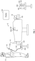
- FIG. 1 depicts a surgical environment "E" in which a medical provider 12 operates an inventory system 10 for detection and counting of beacon tags and radio-frequency identification (RFID) tags to ascertain the presence or absence of items, implements, or objects 100a in a patient 18.
- the inventory system 10 may include a signal generator 120 and an antenna 110 coupled to the signal generator 120 by one or more communication paths, for example, coaxial cable 122.
- the antenna 110 may take the form of a hand-held wand 110a.
- the object 100a may take a variety of forms, for example, instruments, accessories, and/or disposable objects useful in performing surgical procedures.
- the object 100a may take the form of scalpels, scissors, forceps, hemostats, and/or clamps.
- the objects 100a may take the form of surgical sponges, gauze, and/or padding.
- the object 100a is tagged, carrying, attached, or otherwise coupled to an RFID tag 100.
- the medical provider 12 may position the wand 110a approximate the patient 18 in order to detect the presence or absence of the one or more dual detection tags 100 and hence an object 100a.
- the medical provider 12 may, in some aspects, move the wand 110a along and/or across the body of the patient 18.
- U.S. Patent Application Publication No. 2004/0250819 to Blair et al. entitled “Apparatus and Method for Detecting Objects Using Tags and Wideband Detection Device," filed March 29, 2004 , the entire contents of which is hereby incorporated by reference herein.
- the system 10 may include a display 140.
- the display may be used, for example, to display an inventory of potentially retained surgical items.
- inventory system 10 for detection and counting of surgical implements (e.g., object 100a) within a patient's body, includes a signal generator 120 to provide an energizing signal for one or more dual detection tags 100 ( FIG. 1 ) affixed to an object 100a ( FIG. 1 ).
- Each RFID tag 100 is configured to transmit a return signal when energized, such that an antenna 110 can detect the return signal and confirm the presence of objects 100a within the body of patient 18.
- the antenna 110 is operably coupled to the signal generator 120 via a communication cable 122, which may be of variable length to provide greater range of motion to the clinician handling the antenna 110.
- the signal generator 120 may include a controller 200.
- the antenna 110 is an antenna 110 configured to be waved over the surgical site 15, e.g., over the body of patient 18.
- the antenna 110 may be held over the body of the patient 18 at the height of about four or about five inches while attempting to detect dual detection tags 100 (e.g., beacon tags 500 and/or RFID tags 600), so that the user may detect and/or confirm the presence of objects 100a within the body of patient 18.
- dual detection tags 100 e.g., beacon tags 500 and/or RFID tags 600
- the system 10 may further include an RFID-enabled secure package 450 (e.g., RFID-enabled smart packaging and/or RFID enabled secure mutual authentication packaging) which includes an RFID tag affixed thereto.
- an RFID tag may be secured to a lid or a body of the RFID-enabled secure package 450.
- the beacon tag 500 is configured to transmit a first return signal when energized.
- the RFID-enabled secure package 450 will include a surgical item 454 (e.g., cotton swabs) configured to be removed from the RFID-enabled secure package 450.
- the surgical item 454 includes a retained surgical item RFID tag, e.g., the dual detection tag 100, affixed to the surgical item 454.
- the surgical item 454 may include, for example, any surgical sponge, cotton swab, instrument, tool, and/or device that is unintentionally left in the patient at the completion of a surgery or other procedure.
- the RFID tag 500 is configured to transmit a second return signal when energized.
- the RFID-enabled secure package 450 includes, but is not limited to, for example, caps and closures and are generally configured to verify the contents of sealed containers to ensure the product is genuine, not part of a recall, within the expiration date, and/or has not been tampered with or diverted.
- RFID-enabled secure package 450 generally includes a secure package RFID tag 452.
- the retained surgical item dual detection tag 100 may be linked to the secure package RFID tag 452 by embedding an encrypted block of data that contains the unique identifier of the RFID tag 600.
- the RFID tag 600 may be scanned by the antenna 110 in the inventory system 10.
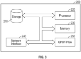
- FIG. 3 illustrates that controller 200 includes a processor 220 connected to a computer-readable storage medium or a memory 230.
- the computer-readable storage medium or memory 230 may be a volatile type of memory, e.g., RAM, or a non-volatile type of memory, e.g., flash media, disk media, etc.
- the processor 220 may be another type of processor such as, without limitation, a digital signal processor, a microprocessor, an ASIC, a graphics processing unit (GPU), a field-programmable gate array (FPGA), or a central processing unit (CPU).
- network inference may also be accomplished in systems that have weights implemented as memristors, chemically, or other inference calculations, as opposed to processors.
- the memory 230 can be random access memory, readonly memory, magnetic disk memory, solid-state memory, optical disc memory, and/or another type of memory. In some aspects of the disclosure, the memory 230 can be separate from the controller 200 and can communicate with the processor 220 through communication buses of a circuit board and/or through communication cables such as serial ATA cables or other types of cables.
- the memory 230 includes computer-readable instructions that are executable by the processor 220 to operate the controller 200.
- the controller 200 may include a network interface 240 to communicate with other computers or to a server.
- a storage device 210 may be used for storing data.
- the dual detection tag 100 generally includes a beacon tag 500 configured to transmit a first return signal at a first frequency when energized and a RFID tag 600 affixed to the beacon tag 500.
- the RFID tag 600 is configured to transmit a second return signal at a second frequency when energized.
- the first frequency is a lower frequency than the second frequency.
- the first frequency may be in the range of about 30 kHz to about 300 kHz and the second frequency may be in the range of about 300MHz to about 3GHz.
- a benefit of the dual detection tag 100 is that it has a small size (e.g., about 12 mm long to about 23 mm long and about 3 mm to about 7mm in diameter), which is desirable to the clinician such that the size does not interfere with the use of a surgical gauze and/or sponge.
- the RFID tag 600 may be disposed around the beacon tag 500.
- the dual detection tag 100 may include a pouch 410 (e.g., a sleeve) made from a biocompatible material (for example, fabric such as cotton and/or polyester), which is configured to hold the beacon tag 500 and the RFID tag 600.
- the pouch 410 may be made of a braided material.
- the pouch is made of a material that is transparent to electromagnetic frequency emissions so as to not block the signals going to and from the beacon tag 500 and the RFID tag 600.
- the beacon tag 500 may be an L-C (inductor-capacitor) resonant tag, such as, for example, a tag having the first frequency range of about 30 kHz to about 300 kHz described above. L-C tags typically have a read range of about 20 cm and generally have a better ability to be transmitted and received in all directions.
- the beacon tag 500 may be used to count and/or identify items inside of a patient 18 ( FIG. 1 ).
- the beacon tag 500 may include a cylindrical shape.
- the RFID tag 600 generally includes a substrate 610, an antenna 620 disposed on the substrate 610, and a transceiver circuit 630 operably connected to the antenna 620.
- the transceiver circuit 630 is configured to transmit and receive RF signals.
- the RFID tag 600 may be an ultra-high frequency (UHF) RFID tag, such as, for example, a tag having a frequency range of about 300MHz to about 3GHz described above. UHF RFID tags typically have a read range of about 12 meters.
- the RFID tag 600 may be used to count and/or identify items outside of a patient 18 ( FIG. 1 ).
- the RFID tag 600 may include a flexible substrate 610 ( FIG. 6 ), such as, for example, polyimide, polyethylene terephthalate, polyethylene naphthalate, and/or polyester.
- the RFID tag 600 may be a thin film UHF RFID tag.
- the dual detection tag 100 may be attached to a surgical item 454 (e.g., surgical gauze and/or a surgical sponge).
- a surgical item 454 e.g., surgical gauze and/or a surgical sponge.
- the pouch 410 of the dual detection tag 100 may be stitched 420 to the surgical item 454, or attached using other suitable methods (e.g., adhesive).
- the two main functions of an inventory system 10 are to detect and count potentially retained surgical items (RSIs).
- retained surgical item includes any surgical sponge, instrument, tool, and/or device that is unintentionally left in the patient at the completion of a surgery or other procedure.
- the disclosed technology detects and counts potential RSIs, each of which includes an RFID, in a secure fashion and in a way that provides individual identification to each RFID based potential retained surgical item.
- a benefit of the disclosed technology is that it does not require that the RFID tag 600 have the capability to perform a cryptographic function such as mutual authentication to assess authenticity.
- the RFID tag 600 of a potential RSI 454 may have limited memory space due to size, cost, or performance constraints yet could still be used in this system.
- the system may include an RFID-enabled secure package 450 (e.g., smart packaging), which includes a set of manufactured potential RSIs 454 (such as cotton sponges).
- the RFID-enabled secure package 450 includes an RFID tag 452 (e.g., an RFID chip), which is capable of mutual authentication with a host (e.g., controller 200).
- the signal generator 120 of the system 10, generates an energizing signal and energizes the dual detection tag 100, which is affixed to a surgical item 454 (e.g., surgical gauze).
- a surgical item 454 e.g., surgical gauze
- the controller 200 of the system 10 receives a return signal from the antenna 110 ( FIG. 1 ).
- the return signal may include a unique identifier.
- the unique identifier may include, for example, an identification code uniquely identifying the RFID tag 452 of the RFID-enabled secure package 450 ( FIG. 1 ).
- the beacon tag 500 (or RFID tag 600) of the dual detection tag 100 may be programmed with unique derived keys based on a unique identifier.
- a derived unique key is a key management scheme in which for every transaction, a unique key is used which is derived from a fixed key.
- a key is a string of characters used within an encryption algorithm for altering data so that it appears random.
- a key locks (encrypts) data so that only a user with the right key can unlock (decrypt) the encrypted data.
- the controller 200 generates a key based on the unique identifier.
- the key may include a symmetric or asymmetric key.
- Symmetric encryption uses mathematical permutations to encrypt a plain text message. It also uses the same mathematical permutation, known as a key, to decrypt messages.
- Asymmetric encryption also uses mathematical permutations to encrypt a plain text message, but it uses two different permutations, still known as keys, to encrypt and decrypt messages. With asymmetric cryptography, a public key that can be shared with anyone gets used to encrypt messages while a private key that is known only by the recipient gets used to decrypt messages.
- the signal generator 120 may energize the RFID tag 600 of the dual detection tag 100 using the generated energizing signal.
- the RFID tag 600 is configured to transmit a second return signal when energized.
- the RSI data block may be as small as 128 bits in the case of Advanced Encryption Standard (AES) encryption in the LF RFID tag, and/or for the UHF RFID chip/tag.
- the derived key may also be based on, for example, a random identifier (RID) and/or a non-unique identifier (NUID).
- the controller 200 receives the second return signal from the antenna 110.
- the return signal includes a data block.
- the beacon tag 500 and/or the RFID tag 600 may include 1K of data.
- the data may be organized into sixteen sectors, and each sector may be organized into about four data blocks. Each block of data may store sixteen bytes of data.
- the controller 200 may decrypt the data-block based on the key and determines if the decrypted data-block includes the unique identifier.
- the decrypted data block may include the 7 bit UID.
- controller 200 may display, on a display 140, an inventory of potentially retained surgical items.
- the system 10 may display the total number of surgical items and their status (e.g., retained and/or accounted for) and may provide an alert if any potentially retained surgical items are not accounted for.
Landscapes
- Engineering & Computer Science (AREA)
- Health & Medical Sciences (AREA)
- Physics & Mathematics (AREA)
- Surgery (AREA)
- Life Sciences & Earth Sciences (AREA)
- Public Health (AREA)
- General Health & Medical Sciences (AREA)
- Medical Informatics (AREA)
- Biomedical Technology (AREA)
- Theoretical Computer Science (AREA)
- Business, Economics & Management (AREA)
- General Business, Economics & Management (AREA)
- Computer Hardware Design (AREA)
- Microelectronics & Electronic Packaging (AREA)
- General Physics & Mathematics (AREA)
- Heart & Thoracic Surgery (AREA)
- Molecular Biology (AREA)
- Animal Behavior & Ethology (AREA)
- Nuclear Medicine, Radiotherapy & Molecular Imaging (AREA)
- Veterinary Medicine (AREA)
- Oral & Maxillofacial Surgery (AREA)
- Pathology (AREA)
- Computer Networks & Wireless Communication (AREA)
- Epidemiology (AREA)
- Primary Health Care (AREA)
- Electromagnetism (AREA)
- Accommodation For Nursing Or Treatment Tables (AREA)
Abstract
An inventory system configured for detecting and counting potentially retained surgical items within a body of a patient includes a dual detection tag, a signal generator, and an antenna operably coupled to the signal generator. The dual detection tag includes a beacon tag configured to transmit a first return signal at a first frequency when energized and a RFID tag affixed configured to transmit a second return signal at a second frequency when energized. The signal generator is configured to generate an energizing signal for the beacon tag and/or the RFID tag. The antenna configured to receive the first return signal transmitted by at least one of the beacon tag or the second return signal transmitted by the RFID tag.
Description
- The present disclosure relates generally to interrogation and detection systems for radio-frequency (RF) tags, and more particularly, detection and inventory systems for potentially retained surgical items within surgical sites.
- It is often useful to determine whether objects associated with a surgery are present in a patient's body before completion of the surgery. Such objects may take a variety of forms. For example, the objects may take the form of instruments, for instance, scalpels, scissors, forceps, hemostats, and/or clamps. Also, for example, the objects may take the form of related accessories and/or disposable objects, for instance, surgical sponges, gauzes, and/or pads. Failure to locate an object before closing the patient may require additional surgery, and in some instances, may have unintended medical consequences.
- Accordingly, there is a need for a technology that is capable of providing both presence detection and tagged surgical item/implement identification functionality in the medical setting, as well as inventory controls of the tagged items/implements. Specifically, detecting the presence of, identifying, and maintaining inventory of tagged surgical items and materials that are used during the execution of a medical procedure. Technologies exist that enable these functions both individually as well as in conjunction with each other, but the methods and packaging of the discrete solutions used are not ideal for the application. More specifically, the components attached or affixed to the items being tracked are either too large physically and present nuisances or obstacles in the execution of the procedure, or the detection and identification performance of the solution may degrade rapidly in the presence of variable and uncontrolled dielectric or conductive materials.
- Accordingly, there are needs for improvements in presence detection, tagged item identification, and inventory functionality in the medical setting.
- This disclosure relates to systems for detection of surgical objects and/or devices used in body cavities during surgery, specifically systems that include a dual detection tag attached to the surgical item and/or devices and an antenna to be placed directly next to a surgical site to detect and track such surgical objects and/or devices.
- In accordance with aspects of the disclosure, an inventory system configured for detecting and counting potentially retained surgical items within a body of a patient includes a dual detection tag, a signal generator, and an antenna operably coupled to the signal generator. The dual detection tag includes a beacon tag configured to transmit a first return signal at a first frequency when energized and an RFID tag affixed configured to transmit a second return signal at a second frequency when energized. The signal generator is configured to generate an energizing signal for the beacon tag and/or the RFID tag. The antenna is configured to receive the first return signal transmitted by the beacon tag and/or the second return signal transmitted by the RFID tag.
- In an aspect of the present disclosure, the first frequency may be a lower frequency than the second frequency.
- In another aspect of the present disclosure, the RFID tag may include a substrate including polyimide, polyethylene terephthalate, polyethylene naphthalate, and/or polyester.
- In yet another aspect of the present disclosure, the RFID tag may include a flexible substrate.
- In a further aspect of the present disclosure, the RFID tag may be disposed around the beacon tag.
- In yet a further aspect of the present disclosure, the dual detection tag may be affixed to a surgical item.
- In an aspect of the present disclosure, the dual detection tag further may include a fabric pouch affixed to the surgical item.
- In yet another aspect of the present disclosure, the system may further include a processor and a memory. The memory includes instructions stored thereon, which, when executed by the processor, may cause the system to energize the beacon tag and receive the first return signal from the antenna. The first return signal includes a first unique identifier.
- In a further aspect of the present disclosure, the instructions, when executed by the processor, may further cause the system to energize the RFID tag and receive the second return signal from the antenna. The second return signal includes a data block.
- In yet a further aspect of the present disclosure, the instructions, when executed by the processor, further cause the system to encrypt the data block, which contains the unique identifier of the dual detection tag.
- In an aspect of the present disclosure, a dual detection tag includes a beacon tag configured to transmit a first return signal in response to a first energizing signal and an RFID tag configured to transmit a second return signal in response to a second energizing signal.
- In accordance with aspects of the disclosure, the first return signal may include a first frequency when energized, and the second return signal may include a second frequency when energized.
- In another aspect of the present disclosure, the first frequency may be a lower frequency than the second frequency.
- In yet another aspect of the present disclosure, the beacon tag may include a cylindrical shape.
- In a further aspect of the present disclosure, the dual detection tag may be contained within a pouch.
- In yet a further aspect of the present disclosure, the pouch may include a material having transparency to electromagnetic frequency emissions.
- In an aspect of the present disclosure, the pouch may be coupled to a surgical instrument.
- In accordance with aspects of the disclosure, the dual detection tag may be coupled to a surgical instrument.
- In yet a further aspect of the present disclosure, the dual detection tag may be coupled to gauze, surgical sponge, and/or padding.
- In an aspect of the present disclosure, the RFID tag may be affixed around an outer face of the beacon tag.
- In the drawings, identical reference numbers identify similar elements or acts. The sizes and relative positions of elements in the drawings are not necessarily drawn to scale. For example, the shapes of various elements and angles are not drawn to scale, and some of these elements are arbitrarily enlarged and positioned to improve drawing legibility. Further, the particular shapes of the elements as drawn are not intended to convey any information regarding the actual shape of the particular elements and have been solely selected for ease of recognition in the drawings.
- Various aspects of the presently disclosed antennae, RF tags, and articles containing them are described herein below with reference to the drawings.
-
FIG. 1 is a schematic diagram showing a surgical environment illustrating a medical provider using an inventory system for detecting and counting an object within a patient that is tagged with an RFID tag according to one illustrated aspect; -
FIG. 2 is a schematic illustration of an antenna for detection of surgical implements within a patient's body in active use within a surgical site; -
FIG. 3 is a block diagram of a controller of the system ofFIG. 1 ; -
FIG. 4 is a diagram of the dual detection tag of the system ofFIG. 1 ; -
FIG. 5 is a diagram of a cylindrical beacon tag of the dual detection tag ofFIG. 4 ; -
FIG. 6 is a diagram of a thin film UHF RFID tag of the dual detection tag ofFIG. 4 ; -
FIG. 7 is a diagram of the dual detection tag ofFIG. 4 attached to a surgical gauze; and -
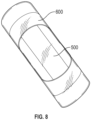
FIG. 8 is a diagram of the thin film UHF RFID tag ofFIG. 6 wrapped around the cylindrical beacon tag ofFIG. 5 . - In the following description, certain specific details are set forth in order to provide a thorough understanding of disclosed aspects. However, one skilled in the relevant art will recognize that aspects may be practiced without one or more of these specific details or with other methods, components, materials, etc. In other instances, well-known structures associated with transmitters, receivers, or transceivers have not been shown or described in detail to avoid unnecessarily obscuring descriptions of the aspects.
- Reference throughout this specification to "one aspect" or "an aspect" means that a particular feature, structure, or characteristic described in connection with the aspect is included in at least one aspect. Thus, the appearances of the phrases "in one aspect" or "in an aspect" in various places throughout this specification are not necessarily all referring to the same aspect. Furthermore, the particular features, structures, or characteristics may be combined in any suitable manner in one or more aspects.
-
FIG. 1 depicts a surgical environment "E" in which amedical provider 12 operates aninventory system 10 for detection and counting of beacon tags and radio-frequency identification (RFID) tags to ascertain the presence or absence of items, implements, orobjects 100a in apatient 18. Theinventory system 10 may include asignal generator 120 and anantenna 110 coupled to thesignal generator 120 by one or more communication paths, for example,coaxial cable 122. In one aspect of theinventory system 10, theantenna 110 may take the form of a hand-heldwand 110a. - The
object 100a may take a variety of forms, for example, instruments, accessories, and/or disposable objects useful in performing surgical procedures. For instance, theobject 100a may take the form of scalpels, scissors, forceps, hemostats, and/or clamps. Also, for example, theobjects 100a may take the form of surgical sponges, gauze, and/or padding. Theobject 100a is tagged, carrying, attached, or otherwise coupled to anRFID tag 100. - In use, the
medical provider 12 may position thewand 110a approximate the patient 18 in order to detect the presence or absence of the one or moredual detection tags 100 and hence anobject 100a. Themedical provider 12 may, in some aspects, move thewand 110a along and/or across the body of thepatient 18. For a detailed description of an exemplary inventory system, reference may be made to commonly ownedU.S. Patent Application Publication No. 2004/0250819 to Blair et al., entitled "Apparatus and Method for Detecting Objects Using Tags and Wideband Detection Device," filed March 29, 2004 , the entire contents of which is hereby incorporated by reference herein. - In aspects, the
system 10 may include adisplay 140. The display may be used, for example, to display an inventory of potentially retained surgical items. - Referring now to
FIG. 2 ,inventory system 10, for detection and counting of surgical implements (e.g.,object 100a) within a patient's body, includes asignal generator 120 to provide an energizing signal for one or more dual detection tags 100 (FIG. 1 ) affixed to anobject 100a (FIG. 1 ). EachRFID tag 100 is configured to transmit a return signal when energized, such that anantenna 110 can detect the return signal and confirm the presence ofobjects 100a within the body ofpatient 18. Theantenna 110 is operably coupled to thesignal generator 120 via acommunication cable 122, which may be of variable length to provide greater range of motion to the clinician handling theantenna 110. Thesignal generator 120 may include acontroller 200. - In one aspect of
inventory system 10, theantenna 110 is anantenna 110 configured to be waved over thesurgical site 15, e.g., over the body ofpatient 18. For example, theantenna 110 may be held over the body of the patient 18 at the height of about four or about five inches while attempting to detect dual detection tags 100 (e.g., beacon tags 500 and/or RFID tags 600), so that the user may detect and/or confirm the presence ofobjects 100a within the body ofpatient 18. - The
system 10 may further include an RFID-enabled secure package 450 (e.g., RFID-enabled smart packaging and/or RFID enabled secure mutual authentication packaging) which includes an RFID tag affixed thereto. For example, an RFID tag may be secured to a lid or a body of the RFID-enabledsecure package 450. Thebeacon tag 500 is configured to transmit a first return signal when energized. Generally, the RFID-enabledsecure package 450 will include a surgical item 454 (e.g., cotton swabs) configured to be removed from the RFID-enabledsecure package 450. Thesurgical item 454 includes a retained surgical item RFID tag, e.g., thedual detection tag 100, affixed to thesurgical item 454. Thesurgical item 454 may include, for example, any surgical sponge, cotton swab, instrument, tool, and/or device that is unintentionally left in the patient at the completion of a surgery or other procedure. TheRFID tag 500 is configured to transmit a second return signal when energized. - The RFID-enabled
secure package 450 includes, but is not limited to, for example, caps and closures and are generally configured to verify the contents of sealed containers to ensure the product is genuine, not part of a recall, within the expiration date, and/or has not been tampered with or diverted. RFID-enabledsecure package 450 generally includes a securepackage RFID tag 452. - In aspects, the retained surgical item
dual detection tag 100 may be linked to the securepackage RFID tag 452 by embedding an encrypted block of data that contains the unique identifier of theRFID tag 600. For example, to enable the use of the retainedsurgical items 454, theRFID tag 600 may be scanned by theantenna 110 in theinventory system 10. -
FIG. 3 illustrates thatcontroller 200 includes aprocessor 220 connected to a computer-readable storage medium or amemory 230. The computer-readable storage medium ormemory 230 may be a volatile type of memory, e.g., RAM, or a non-volatile type of memory, e.g., flash media, disk media, etc. In various aspects of the disclosure, theprocessor 220 may be another type of processor such as, without limitation, a digital signal processor, a microprocessor, an ASIC, a graphics processing unit (GPU), a field-programmable gate array (FPGA), or a central processing unit (CPU). In certain aspects of the disclosure, network inference may also be accomplished in systems that have weights implemented as memristors, chemically, or other inference calculations, as opposed to processors. - In aspects of the disclosure, the
memory 230 can be random access memory, readonly memory, magnetic disk memory, solid-state memory, optical disc memory, and/or another type of memory. In some aspects of the disclosure, thememory 230 can be separate from thecontroller 200 and can communicate with theprocessor 220 through communication buses of a circuit board and/or through communication cables such as serial ATA cables or other types of cables. Thememory 230 includes computer-readable instructions that are executable by theprocessor 220 to operate thecontroller 200. In other aspects of the disclosure, thecontroller 200 may include anetwork interface 240 to communicate with other computers or to a server. Astorage device 210 may be used for storing data. - Referring to
FIG. 4 , there is shown thedual detection tag 100 of the system ofFIG. 1 . Thedual detection tag 100 generally includes abeacon tag 500 configured to transmit a first return signal at a first frequency when energized and aRFID tag 600 affixed to thebeacon tag 500. - The
RFID tag 600 is configured to transmit a second return signal at a second frequency when energized. The first frequency is a lower frequency than the second frequency. For example, the first frequency may be in the range of about 30 kHz to about 300 kHz and the second frequency may be in the range of about 300MHz to about 3GHz. A benefit of thedual detection tag 100 is that it has a small size (e.g., about 12 mm long to about 23 mm long and about 3 mm to about 7mm in diameter), which is desirable to the clinician such that the size does not interfere with the use of a surgical gauze and/or sponge. - The
RFID tag 600 may be disposed around thebeacon tag 500. Thedual detection tag 100 may include a pouch 410 (e.g., a sleeve) made from a biocompatible material (for example, fabric such as cotton and/or polyester), which is configured to hold thebeacon tag 500 and theRFID tag 600. Thepouch 410 may be made of a braided material. In aspects, the pouch is made of a material that is transparent to electromagnetic frequency emissions so as to not block the signals going to and from thebeacon tag 500 and theRFID tag 600. - Referring to
FIG. 5 , thebeacon tag 500 is shown. Thebeacon tag 500 may be an L-C (inductor-capacitor) resonant tag, such as, for example, a tag having the first frequency range of about 30 kHz to about 300 kHz described above. L-C tags typically have a read range of about 20 cm and generally have a better ability to be transmitted and received in all directions. Thebeacon tag 500 may be used to count and/or identify items inside of a patient 18 (FIG. 1 ). Thebeacon tag 500 may include a cylindrical shape. - Referring to
FIG. 6 , theRFID tag 600 is shown. TheRFID tag 600 generally includes asubstrate 610, anantenna 620 disposed on thesubstrate 610, and atransceiver circuit 630 operably connected to theantenna 620. Thetransceiver circuit 630 is configured to transmit and receive RF signals. TheRFID tag 600 may be an ultra-high frequency (UHF) RFID tag, such as, for example, a tag having a frequency range of about 300MHz to about 3GHz described above. UHF RFID tags typically have a read range of about 12 meters. TheRFID tag 600 may be used to count and/or identify items outside of a patient 18 (FIG. 1 ). TheRFID tag 600 may include a flexible substrate 610 (FIG. 6 ), such as, for example, polyimide, polyethylene terephthalate, polyethylene naphthalate, and/or polyester. TheRFID tag 600 may be a thin film UHF RFID tag. - Referring to
FIG. 7 , thedual detection tag 100 may be attached to a surgical item 454 (e.g., surgical gauze and/or a surgical sponge). For example, thepouch 410 of thedual detection tag 100 may be stitched 420 to thesurgical item 454, or attached using other suitable methods (e.g., adhesive). - The two main functions of an inventory system 10 (such as an operating room safety system) are to detect and count potentially retained surgical items (RSIs). The term retained surgical item, as used herein, includes any surgical sponge, instrument, tool, and/or device that is unintentionally left in the patient at the completion of a surgery or other procedure. The disclosed technology detects and counts potential RSIs, each of which includes an RFID, in a secure fashion and in a way that provides individual identification to each RFID based potential retained surgical item.
- A benefit of the disclosed technology is that it does not require that the
RFID tag 600 have the capability to perform a cryptographic function such as mutual authentication to assess authenticity. For example, theRFID tag 600 of apotential RSI 454 may have limited memory space due to size, cost, or performance constraints yet could still be used in this system. - In aspects, the system may include an RFID-enabled secure package 450 (e.g., smart packaging), which includes a set of manufactured potential RSIs 454 (such as cotton sponges). The RFID-enabled
secure package 450 includes an RFID tag 452 (e.g., an RFID chip), which is capable of mutual authentication with a host (e.g., controller 200). - A method of use of the
system 10 anddual detection tag 100, in accordance with the present disclosure, is presented below. Initially, thesignal generator 120, of thesystem 10, generates an energizing signal and energizes thedual detection tag 100, which is affixed to a surgical item 454 (e.g., surgical gauze). - Next, the
controller 200 of thesystem 10 receives a return signal from the antenna 110 (FIG. 1 ). In aspects, the return signal may include a unique identifier. The unique identifier may include, for example, an identification code uniquely identifying theRFID tag 452 of the RFID-enabled secure package 450 (FIG. 1 ). - In aspects, the beacon tag 500 (or RFID tag 600) of the
dual detection tag 100 may be programmed with unique derived keys based on a unique identifier. In cryptography, a derived unique key is a key management scheme in which for every transaction, a unique key is used which is derived from a fixed key. A key is a string of characters used within an encryption algorithm for altering data so that it appears random. A key locks (encrypts) data so that only a user with the right key can unlock (decrypt) the encrypted data. - Next, the
controller 200 generates a key based on the unique identifier. The key may include a symmetric or asymmetric key. Symmetric encryption uses mathematical permutations to encrypt a plain text message. It also uses the same mathematical permutation, known as a key, to decrypt messages. Asymmetric encryption also uses mathematical permutations to encrypt a plain text message, but it uses two different permutations, still known as keys, to encrypt and decrypt messages. With asymmetric cryptography, a public key that can be shared with anyone gets used to encrypt messages while a private key that is known only by the recipient gets used to decrypt messages. - In aspects, the
signal generator 120 may energize theRFID tag 600 of thedual detection tag 100 using the generated energizing signal. TheRFID tag 600 is configured to transmit a second return signal when energized. For example, the RSI data block may be as small as 128 bits in the case of Advanced Encryption Standard (AES) encryption in the LF RFID tag, and/or for the UHF RFID chip/tag. In aspects, the derived key may also be based on, for example, a random identifier (RID) and/or a non-unique identifier (NUID). - Next, the
controller 200 receives the second return signal from theantenna 110. The return signal includes a data block. For example, thebeacon tag 500 and/or theRFID tag 600 may include 1K of data. The data may be organized into sixteen sectors, and each sector may be organized into about four data blocks. Each block of data may store sixteen bytes of data. - Next, the
controller 200 may decrypt the data-block based on the key and determines if the decrypted data-block includes the unique identifier. For example, the decrypted data block may include the 7 bit UID. - In aspects,
controller 200 may display, on adisplay 140, an inventory of potentially retained surgical items. For example, thesystem 10 may display the total number of surgical items and their status (e.g., retained and/or accounted for) and may provide an alert if any potentially retained surgical items are not accounted for. - While several aspects of the disclosure have been shown in the drawings and/or described herein, it is not intended that the disclosure be limited thereto, as it is intended that the disclosure be as broad in scope as the art will allow and that the specification be read likewise. Therefore, the above description should not be construed as limiting but merely as exemplifications of particular aspects. Those skilled in the art will envision other modifications within the scope of the claims appended hereto.
- The invention may be described by reference to the following numbered paragraphs:-
- 1. An inventory system configured for detecting and counting potentially retained surgical items within a body of a patient, the inventory system comprising:
- a dual detection tag including:
- a beacon tag configured to transmit a first return signal at a first frequency when energized; and
- a RFID tag affixed configured to transmit a second return signal at a second frequency when energized;
- a signal generator configured to generate an energizing signal for at least one of the beacon tag or the RFID tag; and
- an antenna operably coupled to the signal generator, the antenna configured to receive at least one of the first return signal transmitted by at least one of the beacon tag or the second return signal transmitted by the RFID tag.
- a dual detection tag including:
- 2. The system of paragraph 1, wherein the first frequency is a lower frequency than the second frequency.
- 3. The system of paragraph 1, wherein the RFID tag includes a substrate including at least one of polyimide, polyethylene terephthalate, polyethylene naphtholate, or polyester.
- 4. The system of paragraph 1, wherein the RFID tag includes a flexible substrate.
- 5. The system of paragraph 4, wherein the RFID tag is disposed around the beacon tag.
- 6. The system of paragraph 5, wherein the dual detection tag is affixed to a surgical item.
- 7. The system of paragraph 6, wherein the dual detection tag further includes a fabric pouch affixed to the surgical item.
- 8. The system of paragraph 1, wherein the system further includes:
- a processor; and
- a memory, including instructions stored thereon, which when executed by the processor cause the system to:
- energize the beacon tag, by the energizing signal; and
- receive the first return signal from the antenna, the first return signal including a first unique identifier.
- 9. The system of paragraph 8, wherein the instructions, when executed by the processor, further cause the system to:
- energize the RFID tag; and
- receive the second return signal from the antenna, the second return signal including a data-block.
- 10. The system of paragraph 9, wherein the instructions, when executed by the processor, further cause the system to encrypt the data-block which contains the unique identifier of the beacon tag.
- 11. A dual detection tag comprising:
- a beacon tag configured to transmit a first return signal in response to a first energizing signal; and
- a RFID tag configured to transmit a second return signal in response to a second energizing signal.
- 12. The dual detection tag of paragraph 11, wherein the first return signal includes a first frequency when energized, and the second return signal includes a second frequency when energized.
- 13. The dual detection tag of
paragraph 12, wherein the first frequency is a lower frequency than the second frequency. - 14. The dual detection tag of paragraph 11, wherein the beacon tag includes a cylindrical shape.
- 15. The dual detection tag of paragraph 11, wherein the dual detection tag is contained within a pouch.
- 16. The dual detection tag of
paragraph 15, wherein the pouch includes a material having transparency to electromagnetic frequency emissions. - 17. The dual detection tag of
paragraph 15, wherein the pouch is coupled to a surgical instrument. - 18. The dual detection tag of paragraph 11, wherein the dual detection tag is coupled to a surgical instrument.
- 19. The dual detection tag of paragraph 11, wherein the dual detection tag is coupled to at least one of gauze, surgical sponge, or padding.
- 20. The dual detection tag of paragraph 11, wherein the RFID tag is affixed around an outer face of the beacon tag.
Claims (15)
- An inventory system configured for detecting and counting potentially retained surgical items within a body of a patient, the inventory system comprising:a dual detection tag including:a beacon tag configured to transmit a first return signal at a first frequency when energized; anda RFID tag affixed configured to transmit a second return signal at a second frequency when energized;a signal generator configured to generate an energizing signal for at least one of the beacon tag or the RFID tag; andan antenna operably coupled to the signal generator, the antenna configured to receive at least one of the first return signal transmitted by at least one of the beacon tag or the second return signal transmitted by the RFID tag.
- The system of claim 1, wherein the first frequency is a lower frequency than the second frequency.
- The system of claim 1 or 2, wherein the RFID tag includes a substrate including at least one of polyimide, polyethylene terephthalate, polyethylene naphtholate, or polyester.
- The system of claim 1, 2 or 3, wherein the RFID tag includes a flexible substrate.
- The system of claim 4, wherein the RFID tag is disposed around the beacon tag, preferably wherein the dual detection tag is affixed to a surgical item yet further preferably wherein the dual detection tag further includes a fabric pouch affixed to the surgical item.
- The system of any preceding claim, wherein the system further includes:a processor; anda memory, including instructions stored thereon, which when executed by the processor cause the system to:energize the beacon tag, by the energizing signal; andreceive the first return signal from the antenna, the first return signal including a first unique identifier.
- The system of claim 6, wherein the instructions, when executed by the processor, further cause the system to:energize the RFID tag; andreceive the second return signal from the antenna, the second return signal including a data-block preferably wherein the instructions, when executed by the processor, further cause the system to encrypt the data-block which contains the unique identifier of the beacon tag.
- A dual detection tag comprising:a beacon tag configured to transmit a first return signal in response to a first energizing signal; anda RFID tag configured to transmit a second return signal in response to a second energizing signal.
- The dual detection tag of claim 11, wherein the first return signal includes a first frequency when energized, and the second return signal includes a second frequency when energized, preferably wherein the first frequency is a lower frequency than the second frequency.
- The dual detection tag of claim 8 or 9, wherein the beacon tag includes a cylindrical shape.
- The dual detection tag of any one of claims 8, 9 or 10, wherein the dual detection tag is contained within a pouch, preferably wherein the pouch includes a material having transparency to electromagnetic frequency emissions.
- The dual detection tag of claim 11, wherein the pouch is coupled to a surgical instrument.
- The dual detection tag of any one of claims 8 to 12, wherein the dual detection tag is coupled to a surgical instrument.
- The dual detection tag of any one of claims 8 to 13, wherein the dual detection tag is coupled to at least one of gauze, surgical sponge, or padding.
- The dual detection tag of any one of claims 8 to 13, , wherein the RFID tag is affixed around an outer face of the beacon tag.
Applications Claiming Priority (2)
| Application Number | Priority Date | Filing Date | Title |
|---|---|---|---|
| US202163230984P | 2021-08-09 | 2021-08-09 | |
| US17/859,530 US12626809B2 (en) | 2021-08-09 | 2022-07-07 | Inventory systems and methods for detecting and counting potentially retained surgical items |
Publications (1)
| Publication Number | Publication Date |
|---|---|
| EP4134038A1 true EP4134038A1 (en) | 2023-02-15 |
Family
ID=83232628
Family Applications (1)
| Application Number | Title | Priority Date | Filing Date |
|---|---|---|---|
| EP22189319.1A Withdrawn EP4134038A1 (en) | 2021-08-09 | 2022-08-08 | Inventory systems and methods for detecting and counting potentially retained surgical items |
Country Status (2)
| Country | Link |
|---|---|
| US (1) | US12626809B2 (en) |
| EP (1) | EP4134038A1 (en) |
Citations (5)
| Publication number | Priority date | Publication date | Assignee | Title |
|---|---|---|---|---|
| US20040250819A1 (en) | 2003-03-27 | 2004-12-16 | Blair William A. | Apparatus and method for detecting objects using tags and wideband detection device |
| WO2006091765A2 (en) * | 2005-02-25 | 2006-08-31 | Osborne Industries, Inc. | Dual frequency identification device |
| US20110174877A1 (en) * | 2006-09-13 | 2011-07-21 | Clearcount Medical Solutions, Inc. | Apparatus and Methods for Monitoring Objects in a Surgical Field |
| CN105373826A (en) * | 2015-11-19 | 2016-03-02 | 上海仪电智能电子有限公司 | Dual-frequency intelligent label |
| WO2016086168A1 (en) * | 2014-11-26 | 2016-06-02 | President And Fellows Of Harvard College | Deposition of rfid tags |
Family Cites Families (114)
| Publication number | Priority date | Publication date | Assignee | Title |
|---|---|---|---|---|
| US2740405A (en) | 1948-08-04 | 1956-04-03 | Howard C Riordan | Surgical sponge with radioactive tracer |
| GB1068747A (en) | 1964-12-09 | 1967-05-10 | Johnson & Johnson | Surgical dressings |
| US3587583A (en) | 1969-07-07 | 1971-06-28 | Irving Melbourne Greenberg | Surgical sponge with magnetized means |
| US4193405A (en) | 1976-08-09 | 1980-03-18 | Micro Tec Instrumentation Inc. | Detectable medical and surgical implements |
| US4114601A (en) | 1976-08-09 | 1978-09-19 | Micro Tec Instrumentation, Inc. | Medical and surgical implement detection system |
| US4422548A (en) | 1982-01-18 | 1983-12-27 | Ritmed Limited | Surgical sponge counter and blood loss determination system |
| US4681111A (en) | 1985-04-05 | 1987-07-21 | Siemens-Pacesetter, Inc. | Analog and digital telemetry system for an implantable device |
| US4658818A (en) | 1985-04-12 | 1987-04-21 | Miller Jr George E | Apparatus for tagging and detecting surgical implements |
| FR2607264B1 (en) | 1986-11-25 | 1989-05-05 | Jacques Lewiner | IMPROVEMENTS TO PROXIMITY IDENTIFICATION DEVICES |
| US5031642A (en) | 1989-04-06 | 1991-07-16 | Nosek Bettie L | Integrator - collector for surgical/medical procedures |
| US5190059A (en) | 1989-11-16 | 1993-03-02 | Fabian Carl E | Surgical implement detector utilizing a powered marker |
| US5107862A (en) | 1991-05-06 | 1992-04-28 | Fabian Carl E | Surgical implement detector utilizing a powered marker |
| US5057095A (en) | 1989-11-16 | 1991-10-15 | Fabian Carl E | Surgical implement detector utilizing a resonant marker |
| US5105829A (en) | 1989-11-16 | 1992-04-21 | Fabian Carl E | Surgical implement detector utilizing capacitive coupling |
| US5188126A (en) | 1989-11-16 | 1993-02-23 | Fabian Carl E | Surgical implement detector utilizing capacitive coupling |
| US5329944A (en) | 1989-11-16 | 1994-07-19 | Fabian Carl E | Surgical implement detector utilizing an acoustic marker |
| EP1357481A3 (en) | 1991-03-07 | 2005-04-27 | Masimo Corporation | Signal processing apparatus and method |
| ES2029423A6 (en) | 1991-03-14 | 1992-08-01 | Grau Galter Jose | Gauze counter apparatus for surgical use. |
| US5235326A (en) | 1991-08-15 | 1993-08-10 | Avid Corporation | Multi-mode identification system |
| US5664582A (en) | 1992-11-17 | 1997-09-09 | Szymaitis; Dennis W. | Method for detecting, distinguishing and counting objects |
| US5456718A (en) | 1992-11-17 | 1995-10-10 | Szymaitis; Dennis W. | Apparatus for detecting surgical objects within the human body |
| US5353011A (en) | 1993-01-04 | 1994-10-04 | Checkpoint Systems, Inc. | Electronic article security system with digital signal processing and increased detection range |
| US5446447A (en) | 1994-02-16 | 1995-08-29 | Motorola, Inc. | RF tagging system including RF tags with variable frequency resonant circuits |
| US5650596A (en) | 1994-08-05 | 1997-07-22 | Surgical Resources, L.L.C. | Automatic surgical sponge counter and blood loss determination system |
| US5923001A (en) | 1994-08-05 | 1999-07-13 | Surgical Resources, L.L.C. | Automatic surgical sponge counter and blood loss determination system |
| US6998541B2 (en) | 1994-08-05 | 2006-02-14 | Clearcount Medical Solutions, Inc. | Automatic surgical sponge counter and blood loss determination system |
| US5629498A (en) | 1995-01-18 | 1997-05-13 | Richard A. Pollock | Intraoperative tracking devices and processes |
| ES2242213T3 (en) | 1996-02-27 | 2005-11-01 | Biosense Webster, Inc. | LOCATION SYSTEM WITH FIELD ACTIVATION SEQUENCES. |
| US6557752B1 (en) | 1996-06-12 | 2003-05-06 | Q-International, Inc. | Smart card for recording identification, and operational, service and maintenance transactions |
| US5886672A (en) | 1997-01-29 | 1999-03-23 | Innotek Pet Products, Inc. | Collapsible antenna |
| US6633226B1 (en) | 1997-08-18 | 2003-10-14 | X-Cyte, Inc. | Frequency hopping spread spectrum passive acoustic wave identification device |
| US5928151A (en) | 1997-08-22 | 1999-07-27 | Acuson Corporation | Ultrasonic system and method for harmonic imaging in three dimensions |
| US6026818A (en) | 1998-03-02 | 2000-02-22 | Blair Port Ltd. | Tag and detection device |
| CA2321674A1 (en) | 1998-03-04 | 1999-09-10 | Trolley Scan (Propietary) Limited | Multi-dimensional electronic identification of articles |
| US6243608B1 (en) | 1998-06-12 | 2001-06-05 | Intermedics Inc. | Implantable device with optical telemetry |
| US6015390A (en) | 1998-06-12 | 2000-01-18 | D. Krag Llc | System and method for stabilizing and removing tissue |
| DE19847135B4 (en) | 1998-10-13 | 2007-10-31 | Texas Instruments Deutschland Gmbh | Method for reading the data stored in a transponder and transponder system for carrying out the method |
| US7590441B2 (en) | 1999-03-11 | 2009-09-15 | Biosense, Inc. | Invasive medical device with position sensing and display |
| US6223137B1 (en) | 1999-03-25 | 2001-04-24 | The University Of Tennessee Research Corporation | Method for marking, tracking, and managing hospital instruments |
| US6232878B1 (en) | 1999-05-20 | 2001-05-15 | Checkpoint Systems, Inc. | Resonant circuit detection, measurement and deactivation system employing a numerically controlled oscillator |
| US6366206B1 (en) | 1999-06-02 | 2002-04-02 | Ball Semiconductor, Inc. | Method and apparatus for attaching tags to medical and non-medical devices |
| US6270460B1 (en) | 1999-06-24 | 2001-08-07 | Acuson Corporation | Apparatus and method to limit the life span of a diagnostic medical ultrasound probe |
| US6515273B2 (en) | 1999-08-26 | 2003-02-04 | Masimo Corporation | System for indicating the expiration of the useful operating life of a pulse oximetry sensor |
| US7508303B2 (en) | 1999-11-10 | 2009-03-24 | Simplexgrinnell Lp | Alarm system with speaker |
| GB9930000D0 (en) | 1999-12-21 | 2000-02-09 | Phaeton Research Ltd | An ingestible device |
| US6879300B2 (en) | 2000-02-08 | 2005-04-12 | Cms Partners, Inc. | Wireless boundary proximity determining and animal containment system and method |
| AU2001268613A1 (en) | 2000-06-20 | 2002-01-02 | Bruce H. Levin | Tracking surgical implements with integrated circuits |
| US6734795B2 (en) | 2000-08-14 | 2004-05-11 | William Raymond Price | Location of lost dentures using RF transponders |
| US6696954B2 (en) | 2000-10-16 | 2004-02-24 | Amerasia International Technology, Inc. | Antenna array for smart RFID tags |
| US7098793B2 (en) | 2000-10-11 | 2006-08-29 | Avante International Technology, Inc. | Tracking system and method employing plural smart tags |
| US6883710B2 (en) | 2000-10-11 | 2005-04-26 | Amerasia International Technology, Inc. | Article tracking system and method |
| EP1239421B1 (en) | 2001-03-08 | 2008-10-15 | EM Microelectronic-Marin SA | Passage detection system for individuals or objects through an entrance-exit with a limited space |
| DE60137192D1 (en) | 2001-03-23 | 2009-02-12 | Em Microelectronic Marin Sa | Wireless communication system between multiple transceivers and transponders |
| US6861954B2 (en) | 2001-03-30 | 2005-03-01 | Bruce H. Levin | Tracking medical products with integrated circuits |
| US7325723B2 (en) | 2001-05-14 | 2008-02-05 | Em Microelectronic-Marin Sa | System and method for detecting persons or objects in definite areas provided each with at least an entrance |
| JP4590161B2 (en) | 2001-05-21 | 2010-12-01 | スコット・ラボラトリーズ・インコーポレイテッド | RF-ID label for medical container |
| US7160258B2 (en) | 2001-06-26 | 2007-01-09 | Entrack, Inc. | Capsule and method for treating or diagnosing the intestinal tract |
| US7135978B2 (en) | 2001-09-14 | 2006-11-14 | Calypso Medical Technologies, Inc. | Miniature resonating marker assembly |
| US7158030B2 (en) | 2001-09-19 | 2007-01-02 | Avante International Technology | Medical assistance and tracking system and method employing smart tags |
| WO2003048810A2 (en) | 2001-12-03 | 2003-06-12 | Fabian Carl E | Portable surgical implement detector |
| US6838990B2 (en) | 2001-12-20 | 2005-01-04 | Calypso Medical Technologies, Inc. | System for excitation leadless miniature marker |
| US6822570B2 (en) | 2001-12-20 | 2004-11-23 | Calypso Medical Technologies, Inc. | System for spatially adjustable excitation of leadless miniature marker |
| US6812842B2 (en) | 2001-12-20 | 2004-11-02 | Calypso Medical Technologies, Inc. | System for excitation of a leadless miniature marker |
| US6650240B2 (en) | 2002-01-18 | 2003-11-18 | Techtalion Limited | Apparatus and method for tracking articles during travel |
| US6786405B2 (en) | 2002-02-28 | 2004-09-07 | Curt Wiedenhoefer | Tissue and implant product supply system and method |
| US6641039B2 (en) | 2002-03-21 | 2003-11-04 | Alcon, Inc. | Surgical procedure identification system |
| US6777623B2 (en) * | 2002-04-17 | 2004-08-17 | M. Daniel Ballard | System and method of tracking surgical sponges |
| US20040008123A1 (en) | 2002-07-15 | 2004-01-15 | Battelle Memorial Institute | System and method for tracking medical devices |
| DE60220406T2 (en) | 2002-09-02 | 2008-01-31 | Em Microelectronic-Marin S.A. | Adaptation of the transmission and reception characteristics of an RFID reader as a function of electromagnetic ambient noise |
| US7256695B2 (en) | 2002-09-23 | 2007-08-14 | Microstrain, Inc. | Remotely powered and remotely interrogated wireless digital sensor telemetry system |
| EP1559170B1 (en) | 2002-10-31 | 2017-11-29 | EM Microelectronic-Marin SA | Reader or transmitter and/or receiver comprising a shrouded antenna |
| US7464713B2 (en) | 2002-11-26 | 2008-12-16 | Fabian Carl E | Miniature magnetomechanical tag for detecting surgical sponges and implements |
| US7019650B2 (en) | 2003-03-03 | 2006-03-28 | Caducys, L.L.C. | Interrogator and interrogation system employing the same |
| US7158754B2 (en) | 2003-07-01 | 2007-01-02 | Ge Medical Systems Global Technology Company, Llc | Electromagnetic tracking system and method using a single-coil transmitter |
| US7399899B2 (en) | 2003-08-28 | 2008-07-15 | Fabian Carl E | Attachment of electronic tags to surgical sponges and implements |
| US7397364B2 (en) | 2003-11-11 | 2008-07-08 | Biosense Webster, Inc. | Digital wireless position sensor |
| US6977504B2 (en) | 2003-12-31 | 2005-12-20 | Calypso Medical Technologies, Inc. | Receiver used in marker localization sensing system using coherent detection |
| US7026927B2 (en) | 2003-12-31 | 2006-04-11 | Calypso Medical Technologies, Inc. | Receiver used in marker localization sensing system and having dithering in excitation pulses |
| US20050284773A1 (en) | 2004-06-29 | 2005-12-29 | Allen John J | Method of preventing reuse in an analyte measuring system |
| EP1786329A1 (en) | 2004-08-16 | 2007-05-23 | Abr, Llc | Rfid transducer alignment system |
| US7423535B2 (en) | 2004-08-26 | 2008-09-09 | Avante International Technology, Inc. | Object monitoring, locating, and tracking method employing RFID devices |
| US7319397B2 (en) | 2004-08-26 | 2008-01-15 | Avante International Technology, Inc. | RFID device for object monitoring, locating, and tracking |
| US7342497B2 (en) | 2004-08-26 | 2008-03-11 | Avante International Technology, Inc | Object monitoring, locating, and tracking system employing RFID devices |
| US20060106368A1 (en) | 2004-11-15 | 2006-05-18 | Smart Technologies, Llc | Smart Surgical Device Operating System With Radio Frequency Identification |
| US7492257B2 (en) | 2004-11-22 | 2009-02-17 | Warsaw Orthopedic, Inc. | Systems and methods for processing surgical instrument tray shipping totes |
| WO2006060781A1 (en) | 2004-12-02 | 2006-06-08 | Smith & Nephew, Inc. | Radio frequency identification for medical devices |
| US7268684B2 (en) | 2004-12-08 | 2007-09-11 | Sdgi Holdings, Inc. | Workstation RFID reader for surgical instruments and surgical instrument trays and methods of using same |
| US20060241399A1 (en) | 2005-02-10 | 2006-10-26 | Fabian Carl E | Multiplex system for the detection of surgical implements within the wound cavity |
| US7420468B2 (en) | 2005-02-10 | 2008-09-02 | Fabian Carl E | Surgical implement detector |
| US20060241396A1 (en) * | 2005-02-10 | 2006-10-26 | Fabian Carl E | Multi-modal detection of surgical sponges and implements |
| US7474223B2 (en) | 2005-04-18 | 2009-01-06 | Warsaw Orthopedic, Inc. | Method and apparatus for implant identification |
| US7362228B2 (en) | 2005-04-28 | 2008-04-22 | Warsaw Orthepedic, Inc. | Smart instrument tray RFID reader |
| US7780613B2 (en) | 2005-06-30 | 2010-08-24 | Depuy Products, Inc. | Apparatus, system, and method for transcutaneously transferring energy |
| US20070005141A1 (en) | 2005-06-30 | 2007-01-04 | Jason Sherman | Apparatus, system, and method for transcutaneously transferring energy |
| US8115600B2 (en) * | 2008-11-19 | 2012-02-14 | Greatbatch Ltd. | RFID detection and identification system including an RFID reader having a limited transmit time and a time-out period to protect a medical device against RFID-associated electromagnetic interference |
| WO2007087447A2 (en) | 2006-01-25 | 2007-08-02 | Health Beacens, Inc. | Surgical procedure |
| US20070239289A1 (en) | 2006-04-11 | 2007-10-11 | Sdgi Holdings, Inc. | System and software for processing containers having tools with associated transmitters |
| US20070265690A1 (en) | 2006-05-12 | 2007-11-15 | Yoav Lichtenstein | Position tracking of passive resonance-based transponders |
| US20070285249A1 (en) | 2006-06-06 | 2007-12-13 | Rf Surgical Systems, Inc. | Method, apparatus and article for detection of transponder tagged objects, for example during surgery |
| US20080051746A1 (en) | 2006-08-23 | 2008-02-28 | Jane Shen-Gunther | Surgical sponge incorporating rfid technology and method of use |
| WO2008061313A1 (en) | 2006-11-24 | 2008-05-29 | Mems-Id Pty Ltd | Tagging methods and apparatus |
| US20080132860A1 (en) | 2006-12-01 | 2008-06-05 | William Smith | Apparatus, system and method for detecting surgical sponges in surgical patients and surgical drapes |
| EP2119025A1 (en) | 2007-02-28 | 2009-11-18 | Rf Surgical Systems, Inc. | Method, apparatus and article for detection of transponder tagged objects, for example during surgery |
| US7898420B2 (en) | 2007-03-12 | 2011-03-01 | Rf Surgical Systems, Inc. | Transponder housing and device to mark implements, such as surgical implements, and method of using same |
| US7696877B2 (en) | 2007-05-01 | 2010-04-13 | Rf Surgical Systems, Inc. | Method, apparatus and article for detection of transponder tagged objects, for example during surgery |
| USD577421S1 (en) | 2008-02-11 | 2008-09-23 | Masco Corporation Of Indiana | Faucet |
| WO2009151946A2 (en) | 2008-05-27 | 2009-12-17 | Rf Surgical Systems, Inc. | Multi-modal transponder and method and apparatus to detect same |
| US8111162B2 (en) | 2008-05-28 | 2012-02-07 | Rf Surgical Systems, Inc. | Method, apparatus and article for detection of transponder tagged objects, for example during surgery |
| EP2192651A1 (en) | 2008-11-27 | 2010-06-02 | Gemalto SA | Radiofrequency communication device with separate antenna |
| US9240625B2 (en) | 2013-03-15 | 2016-01-19 | Vivint, Inc. | Expandable in-wall antenna for a security system control unit |
| US10061948B2 (en) * | 2014-08-25 | 2018-08-28 | Covidien Lp | Systems and methods for emulating RFID transponders of a plurality of medical devices |
| AU2016200113B2 (en) * | 2015-01-21 | 2019-10-31 | Covidien Lp | Wirelessly detectable objects for use in medical procedures and methods of making same |
| WO2018064288A1 (en) | 2016-09-28 | 2018-04-05 | Stryker Corporation | Collapsible detection antenna for surgical articles |
| KR20180130784A (en) | 2017-05-30 | 2018-12-10 | 재단법인 오송첨단의료산업진흥재단 | Direction detecting system capable of real-time location of tumor using gyro sensor and tumor location detection method using the same |
-
2022
- 2022-07-07 US US17/859,530 patent/US12626809B2/en active Active
- 2022-08-08 EP EP22189319.1A patent/EP4134038A1/en not_active Withdrawn
Patent Citations (5)
| Publication number | Priority date | Publication date | Assignee | Title |
|---|---|---|---|---|
| US20040250819A1 (en) | 2003-03-27 | 2004-12-16 | Blair William A. | Apparatus and method for detecting objects using tags and wideband detection device |
| WO2006091765A2 (en) * | 2005-02-25 | 2006-08-31 | Osborne Industries, Inc. | Dual frequency identification device |
| US20110174877A1 (en) * | 2006-09-13 | 2011-07-21 | Clearcount Medical Solutions, Inc. | Apparatus and Methods for Monitoring Objects in a Surgical Field |
| WO2016086168A1 (en) * | 2014-11-26 | 2016-06-02 | President And Fellows Of Harvard College | Deposition of rfid tags |
| CN105373826A (en) * | 2015-11-19 | 2016-03-02 | 上海仪电智能电子有限公司 | Dual-frequency intelligent label |
Also Published As
| Publication number | Publication date |
|---|---|
| US12626809B2 (en) | 2026-05-12 |
| US20230041495A1 (en) | 2023-02-09 |
Similar Documents
| Publication | Publication Date | Title |
|---|---|---|
| JP7201879B2 (en) | Systems and methods for out-of-band pairing of sterile and non-sterile instruments | |
| US12524639B2 (en) | Systems, apparatus and methods for labeling, packaging, and tracking surgical articles | |
| US7872567B2 (en) | Method for transponder access control | |
| US8296852B2 (en) | Transponder, RFID system, and method for RFID system with key management | |
| US20230084032A1 (en) | Systems and methods for localizing retained surgical items combining rfid tags and computer vision | |
| US7760096B2 (en) | Radio frequency identification (RFID) tag encryption method and system using broadcast encryption (BE) scheme | |
| US8947211B2 (en) | Communication data protection method based on symmetric key encryption in RFID system, and apparatus for enabling the method | |
| US8665074B1 (en) | RFID tag chips and tags with alternative behaviors and methods | |
| US12626809B2 (en) | Inventory systems and methods for detecting and counting potentially retained surgical items | |
| US12433711B2 (en) | Inventory systems and methods for detecting and counting potentially retained surgical items | |
| US9069933B1 (en) | Secure, networked portable storage device | |
| KR101053636B1 (en) | Authentication method and system between tag and RFID reader using multiple encryption methods | |
| EP4141740B1 (en) | Inventory systems and methods for detecting and counting potentially retained surgical items | |
| CN117236358A (en) | Surgical gown tracking system and how to use it | |
| US12502230B2 (en) | Inventory systems and methods for retained surgical item detection | |
| ES2833545T3 (en) | Management procedure for at least one container and associated procedures and devices | |
| Rahman et al. | I am not a goldfish in a bowl: A privacy preserving framework for RFID based healthcare systems | |
| EP4648698A1 (en) | Inventory systems and methods for reducing variability in retained surgical item detection | |
| Sarwar et al. | Cost Effective Design of an RFID Based Healthcare Service System | |
| US20140266581A1 (en) | Modular smart label data transmission systems for applied end-user optimization | |
| Polycarpou et al. | A UHF Radio Frequency Identification (RFID) system for healthcare: Design and implementation | |
| Zarmehi et al. | A study on security and privacy in RFID | |
| Rahman | Ensuring Application Specific Security, Privacy and Performance Goals in RFID Systems | |
| BR102013003507A2 (en) | Communication system for secure identification and authentication of radio frequency transponders |
Legal Events
| Date | Code | Title | Description |
|---|---|---|---|
| PUAI | Public reference made under article 153(3) epc to a published international application that has entered the european phase |
Free format text: ORIGINAL CODE: 0009012 |
|
| STAA | Information on the status of an ep patent application or granted ep patent |
Free format text: STATUS: REQUEST FOR EXAMINATION WAS MADE |
|
| 17P | Request for examination filed |
Effective date: 20220808 |
|
| AK | Designated contracting states |
Kind code of ref document: A1 Designated state(s): AL AT BE BG CH CY CZ DE DK EE ES FI FR GB GR HR HU IE IS IT LI LT LU LV MC MK MT NL NO PL PT RO RS SE SI SK SM TR |
|
| STAA | Information on the status of an ep patent application or granted ep patent |
Free format text: STATUS: THE APPLICATION IS DEEMED TO BE WITHDRAWN |
|
| 18D | Application deemed to be withdrawn |
Effective date: 20230817 |