EP4133565B1 - Filter device - Google Patents
Filter device Download PDFInfo
- Publication number
- EP4133565B1 EP4133565B1 EP21735233.5A EP21735233A EP4133565B1 EP 4133565 B1 EP4133565 B1 EP 4133565B1 EP 21735233 A EP21735233 A EP 21735233A EP 4133565 B1 EP4133565 B1 EP 4133565B1
- Authority
- EP
- European Patent Office
- Prior art keywords
- network
- unit
- capacitor
- converter
- voltage
- Prior art date
- Legal status (The legal status is an assumption and is not a legal conclusion. Google has not performed a legal analysis and makes no representation as to the accuracy of the status listed.)
- Active
Links
- 239000003990 capacitor Substances 0.000 claims description 97
- 239000004020 conductor Substances 0.000 claims description 61
- 230000001681 protective effect Effects 0.000 claims description 41
- 238000000034 method Methods 0.000 claims description 12
- 239000004065 semiconductor Substances 0.000 claims description 2
- 238000010438 heat treatment Methods 0.000 description 4
- 238000009795 derivation Methods 0.000 description 3
- 230000007935 neutral effect Effects 0.000 description 3
- 238000010586 diagram Methods 0.000 description 2
- 238000002955 isolation Methods 0.000 description 2
- 230000002265 prevention Effects 0.000 description 2
- 238000000926 separation method Methods 0.000 description 2
- 238000004804 winding Methods 0.000 description 2
- 230000003213 activating effect Effects 0.000 description 1
- 230000006378 damage Effects 0.000 description 1
- 230000001419 dependent effect Effects 0.000 description 1
- 238000005516 engineering process Methods 0.000 description 1
- 230000010354 integration Effects 0.000 description 1
- 238000005070 sampling Methods 0.000 description 1
- 238000011144 upstream manufacturing Methods 0.000 description 1
Images

Classifications
-
- H—ELECTRICITY
- H02—GENERATION; CONVERSION OR DISTRIBUTION OF ELECTRIC POWER
- H02J—CIRCUIT ARRANGEMENTS OR SYSTEMS FOR SUPPLYING OR DISTRIBUTING ELECTRIC POWER; SYSTEMS FOR STORING ELECTRIC ENERGY
- H02J3/00—Circuit arrangements for ac mains or ac distribution networks
- H02J3/26—Arrangements for eliminating or reducing asymmetry in polyphase networks
-
- H—ELECTRICITY
- H02—GENERATION; CONVERSION OR DISTRIBUTION OF ELECTRIC POWER
- H02J—CIRCUIT ARRANGEMENTS OR SYSTEMS FOR SUPPLYING OR DISTRIBUTING ELECTRIC POWER; SYSTEMS FOR STORING ELECTRIC ENERGY
- H02J3/00—Circuit arrangements for ac mains or ac distribution networks
- H02J3/001—Methods to deal with contingencies, e.g. abnormalities, faults or failures
-
- H—ELECTRICITY
- H02—GENERATION; CONVERSION OR DISTRIBUTION OF ELECTRIC POWER
- H02M—APPARATUS FOR CONVERSION BETWEEN AC AND AC, BETWEEN AC AND DC, OR BETWEEN DC AND DC, AND FOR USE WITH MAINS OR SIMILAR POWER SUPPLY SYSTEMS; CONVERSION OF DC OR AC INPUT POWER INTO SURGE OUTPUT POWER; CONTROL OR REGULATION THEREOF
- H02M1/00—Details of apparatus for conversion
- H02M1/12—Arrangements for reducing harmonics from ac input or output
- H02M1/126—Arrangements for reducing harmonics from ac input or output using passive filters
-
- H—ELECTRICITY
- H02—GENERATION; CONVERSION OR DISTRIBUTION OF ELECTRIC POWER
- H02M—APPARATUS FOR CONVERSION BETWEEN AC AND AC, BETWEEN AC AND DC, OR BETWEEN DC AND DC, AND FOR USE WITH MAINS OR SIMILAR POWER SUPPLY SYSTEMS; CONVERSION OF DC OR AC INPUT POWER INTO SURGE OUTPUT POWER; CONTROL OR REGULATION THEREOF
- H02M5/00—Conversion of ac power input into ac power output, e.g. for change of voltage, for change of frequency, for change of number of phases
- H02M5/40—Conversion of ac power input into ac power output, e.g. for change of voltage, for change of frequency, for change of number of phases with intermediate conversion into dc
- H02M5/42—Conversion of ac power input into ac power output, e.g. for change of voltage, for change of frequency, for change of number of phases with intermediate conversion into dc by static converters
- H02M5/44—Conversion of ac power input into ac power output, e.g. for change of voltage, for change of frequency, for change of number of phases with intermediate conversion into dc by static converters using discharge tubes or semiconductor devices to convert the intermediate dc into ac
- H02M5/453—Conversion of ac power input into ac power output, e.g. for change of voltage, for change of frequency, for change of number of phases with intermediate conversion into dc by static converters using discharge tubes or semiconductor devices to convert the intermediate dc into ac using devices of a triode or transistor type requiring continuous application of a control signal
- H02M5/458—Conversion of ac power input into ac power output, e.g. for change of voltage, for change of frequency, for change of number of phases with intermediate conversion into dc by static converters using discharge tubes or semiconductor devices to convert the intermediate dc into ac using devices of a triode or transistor type requiring continuous application of a control signal using semiconductor devices only
- H02M5/4585—Conversion of ac power input into ac power output, e.g. for change of voltage, for change of frequency, for change of number of phases with intermediate conversion into dc by static converters using discharge tubes or semiconductor devices to convert the intermediate dc into ac using devices of a triode or transistor type requiring continuous application of a control signal using semiconductor devices only having a rectifier with controlled elements
-
- H—ELECTRICITY
- H02—GENERATION; CONVERSION OR DISTRIBUTION OF ELECTRIC POWER
- H02M—APPARATUS FOR CONVERSION BETWEEN AC AND AC, BETWEEN AC AND DC, OR BETWEEN DC AND DC, AND FOR USE WITH MAINS OR SIMILAR POWER SUPPLY SYSTEMS; CONVERSION OF DC OR AC INPUT POWER INTO SURGE OUTPUT POWER; CONTROL OR REGULATION THEREOF
- H02M1/00—Details of apparatus for conversion
- H02M1/12—Arrangements for reducing harmonics from ac input or output
- H02M1/123—Suppression of common mode voltage or current
-
- H—ELECTRICITY
- H02—GENERATION; CONVERSION OR DISTRIBUTION OF ELECTRIC POWER
- H02M—APPARATUS FOR CONVERSION BETWEEN AC AND AC, BETWEEN AC AND DC, OR BETWEEN DC AND DC, AND FOR USE WITH MAINS OR SIMILAR POWER SUPPLY SYSTEMS; CONVERSION OF DC OR AC INPUT POWER INTO SURGE OUTPUT POWER; CONTROL OR REGULATION THEREOF
- H02M5/00—Conversion of ac power input into ac power output, e.g. for change of voltage, for change of frequency, for change of number of phases
- H02M5/40—Conversion of ac power input into ac power output, e.g. for change of voltage, for change of frequency, for change of number of phases with intermediate conversion into dc
- H02M5/42—Conversion of ac power input into ac power output, e.g. for change of voltage, for change of frequency, for change of number of phases with intermediate conversion into dc by static converters
- H02M5/44—Conversion of ac power input into ac power output, e.g. for change of voltage, for change of frequency, for change of number of phases with intermediate conversion into dc by static converters using discharge tubes or semiconductor devices to convert the intermediate dc into ac
- H02M5/453—Conversion of ac power input into ac power output, e.g. for change of voltage, for change of frequency, for change of number of phases with intermediate conversion into dc by static converters using discharge tubes or semiconductor devices to convert the intermediate dc into ac using devices of a triode or transistor type requiring continuous application of a control signal
- H02M5/458—Conversion of ac power input into ac power output, e.g. for change of voltage, for change of frequency, for change of number of phases with intermediate conversion into dc by static converters using discharge tubes or semiconductor devices to convert the intermediate dc into ac using devices of a triode or transistor type requiring continuous application of a control signal using semiconductor devices only
-
- Y—GENERAL TAGGING OF NEW TECHNOLOGICAL DEVELOPMENTS; GENERAL TAGGING OF CROSS-SECTIONAL TECHNOLOGIES SPANNING OVER SEVERAL SECTIONS OF THE IPC; TECHNICAL SUBJECTS COVERED BY FORMER USPC CROSS-REFERENCE ART COLLECTIONS [XRACs] AND DIGESTS
- Y02—TECHNOLOGIES OR APPLICATIONS FOR MITIGATION OR ADAPTATION AGAINST CLIMATE CHANGE
- Y02E—REDUCTION OF GREENHOUSE GAS [GHG] EMISSIONS, RELATED TO ENERGY GENERATION, TRANSMISSION OR DISTRIBUTION
- Y02E40/00—Technologies for an efficient electrical power generation, transmission or distribution
- Y02E40/50—Arrangements for eliminating or reducing asymmetry in polyphase networks
Definitions
- the invention relates to a filter device for use in a converter on an alternating voltage network, comprising a choke unit and a capacitor unit.
- common-mode currents Currents in the individual phases of an electrical line are referred to as common-mode currents, which, in contrast to differential-mode currents, each have the same sign with regard to their current direction.
- the push-pull currents add up to zero in terms of their current direction, especially in the fault-free case, in the sum of their currents, i.e. that the total amount of current flowing to a consumer in the phases of an electrical line is equal to the amount of current flowing back from the consumer in the phases. This is particularly true when using a neutral conductor.
- the resulting disturbances are also called symmetrical disturbances or push-pull disturbances.
- Disturbances resulting from the common mode currents are also referred to as asymmetrical disturbances or common mode disturbances.
- Common mode interference is caused, for example, by spark interference in brushed motors, switching power supplies, and frequency converters for electrical machines, with significant electrical losses or loads in electrical devices, in the electrical lines connected to them and ultimately in the energy distribution system (grids, transformers) and energy producers (generators). may occur.
- common-mode filter For a common-mode filter, current-compensated chokes with a choke core are often used as a common-mode choke, with, for example, the turns wound around the common choke core per phase having the same number of turns.
- the common mode filter as a capacitor unit has so-called capacitors connected in a Y configuration (Y capacitor unit), which are connected to a ground potential by means of a protective conductor (PE).
- Y capacitor unit Y capacitor unit
- PE protective conductor
- This common mode filter with a usually very low-resistance connection of the Y capacitor unit via the protective conductor to the ground potential is particularly suitable for deriving the common mode current (the disturbance variable) when operating electrical devices, e.g. converters, on a TT network (TT French: Terre Terre) or TN network (TN French: Terre Neutre) with a network star point grounded to earth potential on the generator side of the network.
- TT network TT French: Terre Terre
- TN network TN French: Terre Neutre
- These networks have at least one of the following designs or connections of the network star point grounded to earth potential, according to which the protective conductor of the electrical line alone, the protective conductor by means of an at least partial combination of neutral conductor (N) and protective conductor or the The neutral conductor of the electrical line is connected solely to the grounded network star point on the generator side of the corresponding network (the power source).
- the Y capacitor unit of a common mode filter with a common mode choke for electrical devices cannot be operated on an IT network (French IT: Isoli Terre) that is monitored in particular for electrical interference, which is... of its phases, especially on the generator side (the power source), are designed to be ungrounded, i.e. isolated from the ground potential.
- IT network French IT: Isoli Terre
- no or only very low leakage currents are permitted, particularly via the Y capacitor unit and the protective conductor to earth potential.
- a TT network or a TN network in which, in contrast to a grounded network star point, there is an external conductor, i.e. a phase of the TT or TN network, on the generator side (the power source ) is connected to the grounded earth potential, no or only very low leakage currents to the earth potential may be permissible here for specific operating states, in particular via the Y capacitor unit and the protective conductor.
- the separation of the Y-capacitor unit from the grounded protective conductor leads, on the one hand, to the prevention or at least to the reduction of the leakage currents or also to a reduction in the voltage load on the capacitors of the Y-capacitor unit, but on the other hand, the current-compensated choke can be periodically driven into saturation, since the Dissipation path for the common mode currents of the common mode interference is ineffective at this point due to the separation of the Y capacitor unit. This can lead to excessive heating of the choke core of the current compensated choke and cause destruction of the common mode choke.
- the EP 2 048 771 A1 discloses a filter device for a drive connected between a rectifier module of a frequency converter and an AC power supply network.
- the filter device comprises an EMC filter with a common mode inductance, which has windings in each phase of the supply network, the windings being magnetically coupled to one another. Saturation of the common mode inductance of the EMC filter should be avoided in the sampling frequency range of the drive and in the resonance frequency range of the EMC filter.
- a circuit arrangement for a frequency converter which consists of a passive, network-side EMC filter and an active filter.
- the passive, network-side EMC filter has a capacitor arrangement of three with the respective phases of the network connected capacitors, which form a star point.
- the star point can be electrically connected to a ground potential via another capacitor using a switch.
- the invention is therefore based on the object of proposing an efficient filter device with a common mode choke and a capacitor unit, which is suitable, on the one hand, for use in a network with a grounded network star point and, on the other hand, for use in a network with a grounded outer conductor or a ground-free network, without the Common mode choke to heat up unacceptably.
- the object is achieved by a filter device with the features specified in claim 1, by a converter with the filter device according to the features specified in claim 8 and by a method for operating the filter device according to the features specified in claim 10.
- a filter device for use in a converter on an alternating voltage network, comprising a throttle unit, a capacitor unit and means for reducing the saturation of the throttle unit.
- the means for reducing the saturation of the throttle unit advantageously prevents the common mode choke from being heated to an inadmissible extent.
- the filter device with the choke unit can therefore be used as a common mode choke together with the capacitor unit for use, for example, of the converter in networks with different grounding concepts.
- Advantageous embodiments of the filter device are specified in the dependent claims.
- the filter device is grounded for a first operation of the converter on a network designed as an alternating voltage network External conductor or on a ground-free network designed as an AC voltage network, the means for reducing saturation being activated and the capacitor unit being separable from a grounded protective conductor.
- the AC voltage network as a network with a grounded outer conductor is advantageously understood to mean, in particular, TT networks or TN networks in which only one of the external conductors on the generator side of the respective network is connected to the earth potential and the ground-free network designed as an AC voltage network is more advantageous
- an IT network is understood in which the electrical phases are electrically insulated from the ground potential, particularly on the generator side of the network.
- an isolation transformer can advantageously be dispensed with.
- the means for reducing saturation in order to be able to prevent the inadmissible heating of the throttle unit, which can be operated as a common mode choke, for as many of its electrical states in the first operation as a result of the saturation reduction.
- the capacitor unit can be separated from the grounded protective conductor in this first operation, which preferably supports the prevention of unacceptable heating of the common mode choke.
- the filter device is prepared for a second operation of the converter on a network designed as an alternating voltage network with a grounded network star point, the capacitor unit being connectable to the grounded protective conductor for dissipating a current and the means for reducing saturation being deactivated.
- the alternating voltage network as a network with a grounded network star point is advantageously understood to mean, in particular, TT networks or TN networks, in which the network star point formed on the generator side of the respective network is connected to the earth potential.
- the capacitor unit In this second operation, it is therefore advantageous to be able to connect the capacitor unit to the grounded protective conductor in order to be able to derive the current that can be generated as a common mode current.
- the means for reducing saturation can preferably be deactivated in the second operation, which can efficiently support the current dissipation of the common mode current.
- the throttle unit comprises a first coil in a first AC voltage phase, a second coil in a second AC voltage phase and a third coil in a third AC voltage phase of the first AC voltage line, the means for reducing saturation has a fourth coil of the throttle unit, the throttle unit forms a common throttle core the first, second, third and fourth coils and the means for reducing saturation has a first contact unit for opening and closing a first electrical connection of a circuit on the fourth coil.
- the inadmissible heating of the common throttle core can advantageously be prevented via the fourth coil on the common throttle core of the throttle unit, which can be operated as a common mode choke, in particular as a current-compensated choke, and via the circuit on the fourth coil which is short-circuited by the first contact unit.
- the common mode current that can be generated as a current in the first operation can be neutralized at the common mode choke in such a way that the common choke core of the common mode choke is not driven into saturation in an impermissible manner, for example periodically.
- the current dissipation of the common mode current via the capacitor unit to the grounded A protective conductor is not necessary to prevent saturation of the common throttle core.
- This is advantageously suitable for using the filter device on the network designed as an AC voltage network with a grounded outer conductor or on the ground-free network designed as an AC voltage network.
- the capacitor unit comprises a first, second and third capacitor, the first capacitor is on the one hand with a first AC voltage phase of the first AC voltage line, the second capacitor on the one hand with a second AC voltage phase of the first AC voltage line and the third capacitor on the one hand with a third AC voltage phase of the first AC voltage line is electrically connected and, on the other hand, the capacitors form a capacitor star point.
- a second contact unit is designed for opening and closing a second electrical connection of the capacitor unit with the grounded protective conductor and the capacitors of the capacitor unit can be electrically connected to the grounded protective conductor via the capacitor star point and the second contact unit.
- the common mode current that can be generated as current in the second operation can advantageously be derived from the capacitor unit via the second contact unit to the grounded protective conductor.
- At least one of the contact units has an electromechanical connector or a semiconductor switch.
- the electromechanical connector can, for example, advantageously be designed as a screw connection but also as an electrical switch.
- At least one of the contact units is designed as a controllable switch.
- a controllable switch can be designed, for example, as an IGBT or MOSFET but also as a relay or contactor.
- At least one of the contact units can be controlled by means of a control signal from a control unit.
- the control unit can be comprised by the filter device but also, for example, by a control unit of the converter.
- It can also be designed as a control unit, which is comprised, for example, by a higher-level drive, automation or energy control. Should the network topology change, the filter device can be switched over in an efficient and advantageous manner, so that the filter device can be used for the first operation or the second operation of the converter.
- the contact units are designed as an electrical changer.
- the electrical changer also known as a changeover switch
- the first and second contact units are switched simultaneously and thus the contact units are switched simultaneously. For example, in a first switching state of the changer, the first contact unit is closed and the second contact unit is open. After activating the changer, it is then in a second switching state of the changer, the first contact unit is opened and the second contact unit is closed.
- This switching process of simultaneously switching the two contact units by the electrical changer can be carried out reversibly.
- the filter device is integrated into a converter housing of the converter.
- the integration of the filter device into the converter housing of the converter has the advantage, for example, that the converter in a compact design always has the filter device for connection to the different network topologies for the first and second operation of the converter and a customer can use the setting on the converter for the can decide for each company.
- a method for operating the filter device according to the invention is also proposed, wherein the filter device for the first operation of the converter is set on the network designed as an AC voltage network with a grounded outer conductor or on the ground-free network designed as an AC voltage network, or the filter device for the second Operation of the converter on the network designed as an AC voltage network with a grounded network star point is set.
- the means for reducing the saturation of the throttle unit is activated and the capacitor unit is separated from the grounded protective conductor.
- the capacitor unit in the second operation of the converter, is connected to the grounded protective conductor for current dissipation and the means for reducing saturation is deactivated.
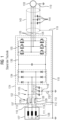
- FIG 1 shows a schematic representation of a known filter device 101, which is electrically arranged on a first AC voltage line 113 and is electrically connected via the first AC voltage line 113 to a rectifier 134 of a converter 124.
- the converter 124 also has an inverter 135, which is electrically coupled to the rectifier 134 by means of a DC intermediate circuit 136.
- the converter 124 is coupled on the output side via the inverter 135 and a second AC voltage line 126 to an electrical machine 133, the electrical Machine 133 is connected to ground potential via a grounded protective conductor 119.
- the second AC voltage line 126 has a line shield 143, which is connected to the grounded protective conductor 119 and thus to the ground potential.
- line capacitances 144 are formed starting from the individual phases of the second AC voltage line 126 relative to the line shield 134.
- the filter device 101 has a choke unit 106 in the form of a common mode choke (current compensated choke) and a capacitor unit 103 on the first AC voltage line 113.
- the throttle unit 102 includes a first coil 106 in a first AC voltage phase 110, a second coil 107 in a second AC voltage phase 111 and a third coil 108 in a third AC voltage phase 112 of the first AC voltage line 113. Furthermore, the throttle unit 102 forms a common throttle core 129 on the first , second and third coils 106,107,108.
- the capacitor unit 103 includes first, second and third capacitors 115,116,117.
- the first capacitor 115 is, on the one hand, connected to the first AC voltage phase 110 of the first AC voltage line 113
- the second capacitor 116 is, on the one hand, connected to the second AC voltage phase 111 of the first AC voltage line 113
- the third capacitor 117 is, on the one hand, connected to the third AC voltage phase 112 of the first AC voltage line 113 and the Capacitors 115,116,117, on the other hand, form a capacitor star point 118.
- the capacitors 115,116,117 of the capacitor unit 103 are connected to the grounded protective conductor 119 via the capacitor star point 118. So a stream 132 can be in the form of a Common mode current is derived relative to the ground potential.
- a further capacitor can be connected in the connection between the capacitor star point 118 and the grounded protective conductor 119 (in FIG 1 Not shown) .
- the converter 124 with the filter device 101 is connected on the input side to an AC voltage network 127 by means of the first AC voltage line 113.
- the AC voltage network 127 is designed as a network with the grounded star point 128, here as a TN network with a grounded star point 128.
- the ground potential for the grounded star point 128 is connected to the protective conductor 119.
- FIG 2 shows in a first schematic representation the filter device 1 according to the invention, which is electrically arranged on a first AC voltage line 13 and is connected to a rectifier 34 of a converter 24 via the first AC voltage line 13.
- the converter 24 also has an inverter 35, which is electrically coupled to the rectifier 34 by means of a DC intermediate circuit 36.
- the converter 24 is coupled on the output side to an electrical machine 33 via the inverter 35 and a second AC voltage line 26, the electrical machine 33 being connected to earth potential via a grounded protective conductor 19.
- the second AC voltage line 26 has a line shield 43, which is connected to the grounded protective conductor 19 and thus to the ground potential.
- line capacitances 44 are formed starting from the individual phases of the second AC voltage line 26 relative to the line shield 34.
- the filter device 1 has a choke unit 6 in the form of a common mode choke (current-compensated choke) and a capacitor unit 3 on the first AC voltage line 3.
- a choke unit 6 in the form of a common mode choke (current-compensated choke) and a capacitor unit 3 on the first AC voltage line 3.
- the throttle unit 2 comprises a first coil 6 in a first AC voltage phase 10, a second coil 7 in a second AC voltage phase 11 and a third coil 8 in a third AC voltage phase 12 of the first AC voltage line 13.
- a means for reducing the saturation of the throttle unit 2 has a fourth coil 9 of the throttle unit 2.
- the means for reducing saturation further comprises a first contact unit 4 for opening and closing a first electrical connection of a circuit 14 on the fourth coil 9.
- the throttle unit 2 forms a common throttle core 29 on the first, second, third and fourth coils 6, 7, 8 .9 out.
- the circuit 14 on the fourth coil is in FIG 2 represented as short-circuited by the first contact unit 4, the means for reducing saturation being activated.
- the capacitor unit 3 includes a first, second and third capacitor 15, 16, 17.
- the first capacitor 15 is on the one hand with the first AC voltage phase 10 of the first AC voltage line 13
- the second capacitor 16 is on the one hand with the second AC voltage phase 11 of the first AC voltage line 13
- the third capacitor 17 is on the one hand with the third AC voltage phase 12 of the first AC voltage line 13 is connected and the capacitors 15, 16, 17 on the other hand form a capacitor star point 18.
- a current 32 in the form of a common mode current for a second operation of the converter 24 is in FIG 2 not derived from the earth potential.
- the two contact units 4.5 each with a controllable switch 22 per contact unit 4.5, can each be controlled alone or together by a control signal 20 from a control unit 21.
- Both contact units 4.5 are designed as an electrical changer 8.
- the converter 24 with the filter device 1 is connected on the input side to an AC voltage network 27 by means of the first AC voltage line 13.
- the AC voltage network 27 is designed as a network with a grounded outer conductor 25, here as a TT network with a grounded outer conductor 25.
- the ground potential for the grounded outer conductor 25 is not connected to the protective conductor 19.
- FIG 2 shown schematic representation of the filter device 1 for a first operation of the converter 24 on the network designed as an AC voltage network 27 with a grounded outer conductor 25.
- the converter 24 with the filter device 1 in this connection can also be connected to an AC voltage network 27 trained ground-free network, for example an IT network.
- the AC voltage network 27 is isolated from ground potential (in FIG 2 not shown) .
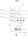
- FIG 3 is a second schematic representation of the filter device 1 according to the invention as a section FIG 2 shown.
- the filter device 1 is electrically arranged on the first alternating voltage line 13.
- the filter device 1 has the choke unit 6 in the form of a common mode choke (current-compensated choke) and the capacitor unit 3 on the first AC voltage line 3.
- the choke unit 6 in the form of a common mode choke (current-compensated choke) and the capacitor unit 3 on the first AC voltage line 3.
- the throttle unit 2 includes the first coil 6 in the first AC voltage phase 10, the second coil 7 in the second AC voltage phase 11 and the third coil 8 in the third AC voltage phase 12 of the first AC voltage line 13.
- the means for reducing the saturation of the throttle unit 2 has the fourth coil 9 of the throttle unit 2.
- the means for reducing saturation further comprises the first contact unit 4 for opening and closing the first electrical connection of the circuit 14 on the fourth coil 9.
- the throttle unit 2 forms the common throttle core 29 on the first, second, third and fourth coils 6, 7, 8 .9 out.
- the circuit 14 on the fourth coil is in FIG 3 represented as short-circuited by the first contact unit 4, the means for reducing saturation being activated.
- the capacitor unit 3 includes the first, second and third capacitors 15, 16, 17.
- the first capacitor 15 is on the one hand with the first AC voltage phase 10 of the first AC voltage line 13
- the second capacitor 16 is, on the one hand, connected to the second AC voltage phase 11 of the first AC voltage line 13
- the third capacitor 17 is, on the one hand, connected to the third AC voltage phase 12 of the first AC voltage line 13 and, on the other hand, the capacitors 15, 16, 17 form the capacitor star point 18.
- a current 32 in the form of a common mode current for the second operation of the converter is in FIG 3 not derived from the earth potential.
- the two contact units 4.5 are in FIG 3 each designed as an electromechanical connector 23 in the form of screw connections 22.
- the screw connection 22 of the second contact unit 5 is shown in dashed lines, which is intended to show the electromechanical connector 23 as open.
- FIG 3 excerpts FIG 2 shown schematic representation of the filter device 1 suitable for a first operation of the converter on the network designed as an AC voltage network with a grounded outer conductor (in FIG 3 Not shown).
- the converter with the filter device 1 in this circuit can also be operated on a ground-free network designed as an AC voltage network, for example an IT network.
- the alternating voltage network is isolated from earth potential (in FIG 3 not shown).
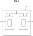
- FIG 4 a schematic structure diagram of a method 38 for the filter device according to the invention is visualized.
- the method 38 shows the operation of the filter device, after which the filter device for the first operation 39 of the converter is set for the network designed as an AC voltage network with a grounded outer conductor or for the ground-free network designed as an AC voltage network or the filter device for the second operation 40 of the converter for that A network designed as an alternating voltage network with a grounded network star point is set.
- the user of the filter device on the converter should decide on one of the two operating modes of the converter, first operation 39 or second operation 40.
- the means for reducing saturation 41 of the throttle unit is activated and the capacitor unit is separated from the grounded protective conductor, with the current derivation 41 being deactivated.
- the capacitor unit is connected to the grounded protective conductor, with the current derivation 42 activated and the means for reducing saturation 41 deactivated.
Description
Die Erfindung betrifft eine Filtervorrichtung zur Verwendung für einen Umrichter an einem Wechselspannungsnetz, aufweisend eine Drosseleinheit und eine Kondensatoreinheit.The invention relates to a filter device for use in a converter on an alternating voltage network, comprising a choke unit and a capacitor unit.
Elektrische Geräte der Antriebs- und Automatisierungstechnik, aber auch der Energieversorgung, können im Betrieb beispielsweise leitungsgebundene und/oder feldgebundene elektrische Störungen erzeugen. Zur Verringerung derartiger Störaussendung kommen für die Verringerung bzw. Vermeidung von Gleichtaktströmen meist Gleichtaktdrosseln in Verbindungen mit Kondensatoreinheiten für entsprechende Filter zum Einsatz.Electrical devices in drive and automation technology, but also in energy supply, can, for example, generate wired and/or field-related electrical interference during operation. To reduce such interference emissions, common mode chokes are usually used in conjunction with capacitor units for corresponding filters to reduce or avoid common mode currents.
Als Gleichtaktströme werden Ströme in den einzelnen Phasen einer elektrischen Leitung bezeichnet, welche, im Gegensatz zu Gegentaktströmen, jeweils das gleiche Vorzeichen bzgl. ihrer Stromrichtung aufweisen.Currents in the individual phases of an electrical line are referred to as common-mode currents, which, in contrast to differential-mode currents, each have the same sign with regard to their current direction.
Die Gegentaktströme hingegen addieren sich bzgl. ihrer Stromrichtung, insbesondere im störungsfreien Fall, in der Summe ihrer Ströme zu Null, d.h. dass der insgesamt in den Phasen einer elektrischen Leitung zu einem Verbraucher hinfließende Strombetrag gleich dem in den Phasen vom Verbraucher zurückfließenden Strombetrag ist. Dies gilt insbesondere auch beim Einsatz eines Nullleiters. Die daraus resultierenden Störgrö-ßen werden auch symmetrische Störungen oder Gegentaktstörungen genannt.The push-pull currents, on the other hand, add up to zero in terms of their current direction, especially in the fault-free case, in the sum of their currents, i.e. that the total amount of current flowing to a consumer in the phases of an electrical line is equal to the amount of current flowing back from the consumer in the phases. This is particularly true when using a neutral conductor. The resulting disturbances are also called symmetrical disturbances or push-pull disturbances.
Da Gleichtaktströme zum Verbraucher hin die gleiche Stromrichtung aufweisen, nimmt deren Rückstrom über elektrostatische Kapazitäten, insbesondere über Leitungskapazitäten, seinen Weg über geerdete Bauelemente der elektrischen Geräte bzw. über die Umgebungserde hin zum Energieerzeuger.Since common mode currents have the same current direction towards the consumer, their return current travels via electrostatic capacitances, in particular via line capacitances, via grounded components of the electrical devices or via the surrounding earth to the energy generator.
Aus den Gleichtaktströmen resultierende Störgrößen werden auch als asymmetrische Störungen oder Gleichtaktstörungen bezeichnet.Disturbances resulting from the common mode currents are also referred to as asymmetrical disturbances or common mode disturbances.
Verursacht werden Gleichtaktstörungen beispielsweise durch Funkenstörungen bei Bürstenmotoren, durch Schaltnetzteile, und Frequenzumrichter für elektrische Maschinen, wobei auch signifikante elektrische Verluste bzw. Belastungen bei elektrischen Geräten, bei mit ihnen verbundenen elektrischen Leitungen und letztendlich bei Energieverteilungssystem (Netze, Transformatoren) und Energieerzeuger (Generatoren) auftreten können.Common mode interference is caused, for example, by spark interference in brushed motors, switching power supplies, and frequency converters for electrical machines, with significant electrical losses or loads in electrical devices, in the electrical lines connected to them and ultimately in the energy distribution system (grids, transformers) and energy producers (generators). may occur.
Für einen Gleichtaktfilter werden häufig stromkompensierte Drosseln mit Drosselkern als Gleichtaktdrossel verwendet, wobei beispielsweise die jeweils pro Phase um den gemeinsamen Drosselkern gewickelten Windungen die gleiche Windungszahl aufweisen.For a common-mode filter, current-compensated chokes with a choke core are often used as a common-mode choke, with, for example, the turns wound around the common choke core per phase having the same number of turns.
Ferner weist der Gleichtaktfilter als Kondensatoreinheit sogenannte in Y-Konfiguration von verschalteten Kondensatoren (Y-Kondensatoreinheit) auf, welche mittels eines Schutzleiters (PE) mit einem Erdpotential verbunden sind.Furthermore, the common mode filter as a capacitor unit has so-called capacitors connected in a Y configuration (Y capacitor unit), which are connected to a ground potential by means of a protective conductor (PE).
Dieser Gleichtaktfilter mit einer meist sehr niederohmigen Verbindung der Y-Kondensatoreinheit über den Schutzleiter mit dem Erdpotential eignet sich besonders für die Ableitung des Gleichtaktstroms (der Störgröße) beim Betrieb von elektrischen Geräten, z.B. Umrichtern, an einem TT-Netz (TT franz.: Terre Terre) oder TN-Netz (TN franz.: Terre Neutre) mit einem auf Erdpotential geerdeten Netzsternpunkt an der Erzeugerseite des Netzes.This common mode filter with a usually very low-resistance connection of the Y capacitor unit via the protective conductor to the ground potential is particularly suitable for deriving the common mode current (the disturbance variable) when operating electrical devices, e.g. converters, on a TT network (TT French: Terre Terre) or TN network (TN French: Terre Neutre) with a network star point grounded to earth potential on the generator side of the network.
Diese Netze weisen zumindest eine der folgenden Auslegungen bzw. Anschaltungen des auf Erdpotential geerdeten Netzsternpunkt auf, wonach der Schutzleiter der elektrischen Leitung allein, der Schutzleiter mittels einer zumindest teilweisen Kombination von Nullleiter (N) und Schutzleiter oder der Nullleiter der elektrischen Leitung allein mit dem geerdeten Netzsternpunkt an der Erzeugerseite des entsprechenden Netzes (der Stromquelle) verbunden ist.These networks have at least one of the following designs or connections of the network star point grounded to earth potential, according to which the protective conductor of the electrical line alone, the protective conductor by means of an at least partial combination of neutral conductor (N) and protective conductor or the The neutral conductor of the electrical line is connected solely to the grounded network star point on the generator side of the corresponding network (the power source).
Die über den Schutzleiter mit dem Erdpotential verbundene Y-Kondensatoreinheit eines Gleichtaktfilters mit Gleichtaktdrossel für elektrische Geräte, wie z.B. Umrichtern, kann jedoch nicht an einem insbesondere auf elektrische Störungen überwachten IT-Netz (IT franz.: Isolé Terre) betrieben werden, welches bzgl. seiner Phasen insbesondere an der Erzeugerseite (der Stromquelle) erdungsfrei, also gegenüber dem Erdpotential isoliert, ausgelegt sind. Hier sind im störungsfreien Betrieb keine oder nur sehr geringe Ableitströme insbesondere über die Y-Kondensatoreinheit und den Schutzleiter an das Erdpotential zulässig.However, the Y capacitor unit of a common mode filter with a common mode choke for electrical devices, such as converters, which is connected to the earth potential via the protective conductor, cannot be operated on an IT network (French IT: Isolé Terre) that is monitored in particular for electrical interference, which is... of its phases, especially on the generator side (the power source), are designed to be ungrounded, i.e. isolated from the ground potential. Here, in trouble-free operation, no or only very low leakage currents are permitted, particularly via the Y capacitor unit and the protective conductor to earth potential.
Kommt ein Betrieb von elektrischen Geräten, wie z.B. Umrichtern, an einem TT-Netz oder einem TN-Netz zum Einsatz, bei denen im Gegensatz zu einem geerdeten Netzsternpunkt ein Außenleiter also eine Phase des TT- oder TN-Netzes an der Erzeugerseite (der Stromquelle) mit dem geerdeten Erdpotential verbunden ist, können auch hier für spezifische Betriebszustände keine oder nur sehr geringe Ableitströme insbesondere über die Y-Kondensatoreinheit und den Schutzleiter an das Erdpotential zulässig sein.If electrical devices, such as converters, are used on a TT network or a TN network, in which, in contrast to a grounded network star point, there is an external conductor, i.e. a phase of the TT or TN network, on the generator side (the power source ) is connected to the grounded earth potential, no or only very low leakage currents to the earth potential may be permissible here for specific operating states, in particular via the Y capacitor unit and the protective conductor.
Bisher ist es daher vorsorglich meist üblich, solche elektrischen Geräte mittels eines vorgeschalteten Trenntransformator an erdungsfreien IT-Netzen oder TN- und TT-Netzen mit geerdetem Außenleiter zu betreiben, wobei der Trenntransformator sekundärseitig einen geerdeten Netzsternpunkt aufweisen muss und sehr kostenintensiv und bauraumverbrauchend ist.So far, as a precautionary measure, it has usually been common practice to operate such electrical devices using an upstream isolating transformer on unearthed IT networks or TN and TT networks with a grounded outer conductor, whereby the isolating transformer must have a grounded network star point on the secondary side and is very cost-intensive and takes up space.
Ferner besteht die Möglichkeit, die Y-Kondensatoreinheit an dem entsprechenden elektrischen Gerät zu entfernen oder die Verbindung zu dem geerdeten Schutzleiter und damit dem Erdpotential aufzutrennen. Dies ist jedoch im Allgemeinen nur möglich, wenn keine stromkompensierte Drossel im Filter am elektrischen Gerät eingesetzt wird.It is also possible to remove the Y capacitor unit on the corresponding electrical device or to disconnect the connection to the grounded protective conductor and thus the ground potential. However, this is generally only possible if no current-compensated choke is used in the filter on the electrical device.
Das Auftrennen der Y-Kondensatoreinheit von dem geerdeten Schutzleiter führt zwar einerseits zur Verhinderung oder zumindest zur Verringerung der Ableitströme bzw. auch zu einer Verringerung der Spannungsbelastung der Kondensatoren der Y-Kondensatoreinheit, jedoch kann andererseits die stromkompensierte Drossel periodisch in Sättigung getrieben werden, da der Ableitpfad für die Gleichtaktströme der Gleichtaktstörungen durch die Auftrennung die Y-Kondensatoreinheit an dieser Stelle unwirksam ist. Dies kann zu einer übermäßigen Erwärmung des Drosselkerns der stromkompensierten Drossel führen und eine Zerstörung der Gleichtaktdrossel hervorrufen.The separation of the Y-capacitor unit from the grounded protective conductor leads, on the one hand, to the prevention or at least to the reduction of the leakage currents or also to a reduction in the voltage load on the capacitors of the Y-capacitor unit, but on the other hand, the current-compensated choke can be periodically driven into saturation, since the Dissipation path for the common mode currents of the common mode interference is ineffective at this point due to the separation of the Y capacitor unit. This can lead to excessive heating of the choke core of the current compensated choke and cause destruction of the common mode choke.
Auch ist es natürlich ferner möglich, die stromkompensierte Drossel derart überdimensioniert auszulegen, dass sie für alle denkbaren Einsatzfälle bei einer Auftrennung der Verbindung zwischen Y- Kondensatoreinheit und dem geerdetem Schutzleiter gerüstet ist, wobei dieses Vorgehen in ineffizienter Weise zu hohen Kosten und einem hohen Bauraumverbrauch führt.It is of course also possible to design the current-compensated choke in such an oversized manner that it is equipped for all conceivable applications when the connection between the Y capacitor unit and the grounded protective conductor is severed, although this procedure inefficiently leads to high costs and a high consumption of space .
Die
In der
Der Erfindung liegt daher die Aufgabe zugrunde, eine effiziente Filtervorrichtung mit einer Gleichtaktdrossel und einer Kondensatoreinheit vorzuschlagen, welche einerseits für den Einsatz in einem Netz mit geerdetem Netzsternpunkt und andererseits für den Einsatz in einem Netz mit geerdetem Außenleiter oder einem erdungsfreien Netz geeignet ist, ohne die Gleichtaktdrossel unzulässig zu erwärmen.The invention is therefore based on the object of proposing an efficient filter device with a common mode choke and a capacitor unit, which is suitable, on the one hand, for use in a network with a grounded network star point and, on the other hand, for use in a network with a grounded outer conductor or a ground-free network, without the Common mode choke to heat up unacceptably.
Die Aufgabe wird durch eine Filtervorrichtung mit den in Anspruch 1 angegebenen Merkmalen, durch einen Umrichter mit der Filtervorrichtung nach den in Anspruch 8 angegebenen Merkmalen und durch ein Verfahren zum Betrieb der Filtervorrichtung nach den in Anspruch 10 angegebenen Merkmalen gelöst.The object is achieved by a filter device with the features specified in
Für die Lösung der Aufgabe wird eine Filtervorrichtung zur Verwendung für einen Umrichter an einem Wechselspannungsnetz vorgeschlagen, aufweisend eine Drosseleinheit, eine Kondensatoreinheit und Mittel zur Sättigungsminderung der Drosseleinheit.To solve the problem, a filter device is proposed for use in a converter on an alternating voltage network, comprising a throttle unit, a capacitor unit and means for reducing the saturation of the throttle unit.
Das Mittel zur Sättigungsminderung der Drosseleinheit verhindert in vorteilhafter Weise, dass die Gleichtaktdrossel unzulässig erwärmt wird. Somit ist die Filtervorrichtung mit der Drosseleinheit als Gleichtaktdrossel gemeinsam mit der Kondensatoreinheit für den Einsatz beispielsweise des Umrichters an Netzen mit unterschiedlichen Erdungskonzepten einsetzbar. Vorteilhafte Ausgestaltungsformen der Filtervorrichtung sind in den abhängigen Ansprüchen angegeben.The means for reducing the saturation of the throttle unit advantageously prevents the common mode choke from being heated to an inadmissible extent. The filter device with the choke unit can therefore be used as a common mode choke together with the capacitor unit for use, for example, of the converter in networks with different grounding concepts. Advantageous embodiments of the filter device are specified in the dependent claims.
Erfindungsgemäß ist die Filtervorrichtung für einen ersten Betrieb des Umrichters an einem als Wechselspannungsnetz ausgebildeten Netz mit geerdetem Außenleiter oder an einem als Wechselspannungsnetz ausgebildeten erdungsfreien Netz hergerichtet, wobei das Mittel zur Sättigungsminderung aktivierbar und die Kondensatoreinheit von einem geerdeten Schutzleiter trennbar ist.According to the invention, the filter device is grounded for a first operation of the converter on a network designed as an alternating voltage network External conductor or on a ground-free network designed as an AC voltage network, the means for reducing saturation being activated and the capacitor unit being separable from a grounded protective conductor.
Unter dem Wechselspannungsnetz als Netz mit geerdetem Außenleiter werden in vorteilhafter Weise insbesondere TT-Netze oder TN-Netze verstanden, bei denen nur einer der Außenleiter an der Erzeugerseite des jeweiligen Netzes mit dem Erdpotential verbunden ist und unter dem als Wechselspannungsnetz ausgebildeten erdungsfreien Netz wird in vorteilhafter Weise insbesondere ein IT-Netz verstanden, bei dem die elektrischen Phasen insbesondere an der Erzeugerseite des Netzes gegenüber dem Erdpotential elektrisch isoliert sind.The AC voltage network as a network with a grounded outer conductor is advantageously understood to mean, in particular, TT networks or TN networks in which only one of the external conductors on the generator side of the respective network is connected to the earth potential and the ground-free network designed as an AC voltage network is more advantageous In particular, an IT network is understood in which the electrical phases are electrically insulated from the ground potential, particularly on the generator side of the network.
Zum Betrieb der Filtervorrichtung an den Netzen mit geerdetem Außenleiter oder an dem erdungsfreien Netz kann vorteilhaft auf einen Trenntransformator verzichtet werden.To operate the filter device on the networks with a grounded outer conductor or on the ground-free network, an isolation transformer can advantageously be dispensed with.
In diesem ersten Betrieb ist es somit vorteilhaft, das Mittel zur Sättigungsminderung aktivieren zu können, um die unzulässige Erwärmung der als Gleichtaktdrossel betreibbaren Drosseleinheit für möglichst jeden ihrer elektrischen Zustände im ersten Betrieb durch die Sättigungsminderung verhindern zu können. Die Kondensatoreinheit kann in diesem ersten Betrieb von dem geerdeten Schutzleiter getrennt werden, was die Verhinderung der unzulässigen Erwärmung der Gleichtaktdrossel bevorzugt unterstützt.In this first operation, it is therefore advantageous to be able to activate the means for reducing saturation in order to be able to prevent the inadmissible heating of the throttle unit, which can be operated as a common mode choke, for as many of its electrical states in the first operation as a result of the saturation reduction. The capacitor unit can be separated from the grounded protective conductor in this first operation, which preferably supports the prevention of unacceptable heating of the common mode choke.
Erfindungsgemäß ist die Filtervorrichtung für einen zweiten Betrieb des Umrichters an einem als Wechselspannungsnetz ausgebildeten Netz mit geerdetem Netzsternpunkt hergerichtet, wobei die Kondensatoreinheit mit dem geerdeten Schutzleiter zur Stromableitung eines Stroms verbindbar und das Mittel zur Sättigungsminderung deaktivierbar ist.According to the invention, the filter device is prepared for a second operation of the converter on a network designed as an alternating voltage network with a grounded network star point, the capacitor unit being connectable to the grounded protective conductor for dissipating a current and the means for reducing saturation being deactivated.
Unter dem Wechselspannungsnetz als Netz mit geerdetem Netzsternpunkt werden in vorteilhafter Weise insbesondere TT-Netze oder TN-Netze verstanden, bei denen der an der Erzeugerseite des jeweiligen Netzes gebildete Netzsternpunkt mit dem Erdpotential verbunden ist.The alternating voltage network as a network with a grounded network star point is advantageously understood to mean, in particular, TT networks or TN networks, in which the network star point formed on the generator side of the respective network is connected to the earth potential.
In diesem zweiten Betrieb ist es somit vorteilhaft, die Kondensatoreinheit mit dem geerdeten Schutzleiter verbinden zu können, um den als Gleichtaktstrom erzeugbaren Strom ableiten zu können. Das Mittel zur Sättigungsminderung kann im zweiten Betrieb bevorzugt deaktiviert werden, was die Stromableitung des Gleichtaktstroms effizient unterstützen kann.In this second operation, it is therefore advantageous to be able to connect the capacitor unit to the grounded protective conductor in order to be able to derive the current that can be generated as a common mode current. The means for reducing saturation can preferably be deactivated in the second operation, which can efficiently support the current dissipation of the common mode current.
Erfindungsgemäß umfasst die Drosseleinheit eine erste Spule in einer ersten Wechselspannungsphase, eine zweite Spule in einer zweiten Wechselspannungsphase und eine dritte Spule in einer dritten Wechselspannungsphase der ersten Wechselspannungsleitung, weist das Mittel zur Sättigungsminderung eine vierte Spule der Drosseleinheit auf, bildet die Drosseleinheit einen gemeinsamen Drosselkern an der ersten, zweiten, dritten und vierten Spule aus und weist das Mittel zur Sättigungsminderung eine erste Kontakteinheit zum Öffnen und Schließen einer ersten elektrischen Verbindung eines Stromkreises an der vierten Spule auf.According to the invention, the throttle unit comprises a first coil in a first AC voltage phase, a second coil in a second AC voltage phase and a third coil in a third AC voltage phase of the first AC voltage line, the means for reducing saturation has a fourth coil of the throttle unit, the throttle unit forms a common throttle core the first, second, third and fourth coils and the means for reducing saturation has a first contact unit for opening and closing a first electrical connection of a circuit on the fourth coil.
Über die vierte Spule an dem gemeinsamen Drosselkern der Drosseleinheit, welche als Gleichtaktdrossel, insbesondere als stromkompensierte Drossel, betreibbar ist, und über den durch die erste Kontakteinheit kurzgeschlossenen Stromkreis an der vierten Spule, kann in vorteilhafter Weise die unzulässige Erwärmung des gemeinsamen Drosselkerns verhindert werden. Der im ersten Betrieb als Strom erzeugbare Gleichtaktstrom kann derart an der Gleichtaktdrossel neutralisiert werden, dass der gemeinsame Drosselkern der Gleichtaktdrossel nicht in unzulässiger Weise, beispielsweise periodisch, in eine Sättigung getrieben wird. Die Stromableitung des Gleichtaktstroms über die Kondensatoreinheit zum geerdeten Schutzleiter ist zur Verhinderung der Sättigung des gemeinsamen Drosselkerns nicht notwendig.The inadmissible heating of the common throttle core can advantageously be prevented via the fourth coil on the common throttle core of the throttle unit, which can be operated as a common mode choke, in particular as a current-compensated choke, and via the circuit on the fourth coil which is short-circuited by the first contact unit. The common mode current that can be generated as a current in the first operation can be neutralized at the common mode choke in such a way that the common choke core of the common mode choke is not driven into saturation in an impermissible manner, for example periodically. The current dissipation of the common mode current via the capacitor unit to the grounded A protective conductor is not necessary to prevent saturation of the common throttle core.
Dies eignet sich vorteilhaft für den Einsatz der Filtervorrichtung an dem als Wechselspannungsnetz ausgebildeten Netz mit geerdetem Außenleiter oder an dem als Wechselspannungsnetz ausgebildeten erdungsfreien Netz.This is advantageously suitable for using the filter device on the network designed as an AC voltage network with a grounded outer conductor or on the ground-free network designed as an AC voltage network.
Bei einer weiteren vorteilhaften Ausgestaltungsform der Filtervorrichtung umfasst die Kondensatoreinheit einen ersten, zweiten und dritten Kondensator, ist der erste Kondensator einerseits mit einer ersten Wechselspannungsphase der ersten Wechselspannungsleitung, der zweite Kondensator einerseits mit einer zweiten Wechselspannungsphase der ersten Wechselspannungsleitung und der dritte Kondensator einerseits mit einer dritten Wechselspannungsphase der ersten Wechselspannungsleitung elektrisch verbunden und bilden die Kondensatoren andererseits einen Kondensatorsternpunkt aus.In a further advantageous embodiment of the filter device, the capacitor unit comprises a first, second and third capacitor, the first capacitor is on the one hand with a first AC voltage phase of the first AC voltage line, the second capacitor on the one hand with a second AC voltage phase of the first AC voltage line and the third capacitor on the one hand with a third AC voltage phase of the first AC voltage line is electrically connected and, on the other hand, the capacitors form a capacitor star point.
Bei einer weiteren vorteilhaften Ausgestaltungsform der Filtervorrichtung ist eine zweite Kontakteinheit zum Öffnen und Schließen einer zweiten elektrischen Verbindung der Kondensatoreinheit mit dem geerdeten Schutzleiter ausgebildet und sind die Kondensatoren der Kondensatoreinheit über den Kondensatorsternpunkt und die zweite Kontakteinheit mit dem geerdeten Schutzleiter elektrisch verbindbar.In a further advantageous embodiment of the filter device, a second contact unit is designed for opening and closing a second electrical connection of the capacitor unit with the grounded protective conductor and the capacitors of the capacitor unit can be electrically connected to the grounded protective conductor via the capacitor star point and the second contact unit.
Der im zweiten Betrieb als Strom erzeugbare Gleichtaktstrom kann vorteilhaft von der Kondensatoreinheit über die zweite Kontakteinheit zum geerdeten Schutzleiter abgeleitet werden.The common mode current that can be generated as current in the second operation can advantageously be derived from the capacitor unit via the second contact unit to the grounded protective conductor.
Bei einer weiteren vorteilhaften Ausgestaltungsform der Filtervorrichtung weist mindestens eine der Kontakteinheiten einen elektromechanischen Verbinder oder einen Halbleiterschalter auf.In a further advantageous embodiment of the filter device, at least one of the contact units has an electromechanical connector or a semiconductor switch.
In einer einfachen Form kann der elektromechanische Verbinder zum Beispiel in vorteilhafter Weise als eine Schraubverbindungen aber auch als elektrischer Schalter ausgebildet sein.In a simple form, the electromechanical connector can, for example, advantageously be designed as a screw connection but also as an electrical switch.
Bei einer weiteren vorteilhaften Ausgestaltungsform der Filtervorrichtung ist mindestens eine der Kontakteinheiten als ansteuerbarer Schalter ausgebildet.In a further advantageous embodiment of the filter device, at least one of the contact units is designed as a controllable switch.
Ein ansteuerbarer Schalter kann beispielsweise als IGBT oder MOSFET aber auch als Relais oder Schütz ausgebildet sein.A controllable switch can be designed, for example, as an IGBT or MOSFET but also as a relay or contactor.
Bei einer weiteren vorteilhaften Ausgestaltungsform der Filtervorrichtung ist mindestens eine der Kontakteinheiten mittels eines Ansteuersignals einer Steuereinheit ansteuerbar.In a further advantageous embodiment of the filter device, at least one of the contact units can be controlled by means of a control signal from a control unit.
Die Steuereinheit kann von der Filtervorrichtung aber beispielsweise auch von einer Steuereinheit des Umrichters umfasst sein.The control unit can be comprised by the filter device but also, for example, by a control unit of the converter.
Sie kann ebenfalls als Steuereinheit ausgebildet sein, welche beispielsweise von einer überlagerten Antriebs-, Automatisierung- oder Energiesteuerung umfasst wird. Sollte sich die Netztopologie ändern, kann auf effiziente und vorteilhaft Weise eine Umschaltung der Filtervorrichtung erfolgen, so dass die Filtervorrichtung für den ersten Betrieb oder den zweiten Betrieb des Umrichters einsetzbar ist.It can also be designed as a control unit, which is comprised, for example, by a higher-level drive, automation or energy control. Should the network topology change, the filter device can be switched over in an efficient and advantageous manner, so that the filter device can be used for the first operation or the second operation of the converter.
Bei einer weiteren vorteilhaften Ausgestaltungsform der Filtervorrichtung sind die Kontakteinheiten als ein elektrischer Wechsler ausgebildet.In a further advantageous embodiment of the filter device, the contact units are designed as an electrical changer.
Mittels des elektrischen Wechslers, auch bekannt als Wechselschalter, erfolgt das gleichzeitige Umschalten der ersten und der zweiten Kontakteinheit und somit eine gleichzeitige Umschaltung der Kontakteinheiten. Beispielweise ist in einem ersten Schaltzustand des Wechslers die erste Kontakteinheit geschlossen und die zweite Kontakteinheit geöffnet. Nach Aktivierung des Wechslers ist danach in einem zweiten Schaltzustand des Wechslers die erste Kontakteinheit geöffnet und die zweite Kontakteinheit geschlossen. Dieser Schaltvorgang des gleichzeitigen Umschaltens der beiden Kontakteinheiten durch den elektrischen Wechsler ist reversibel durchführbar.By means of the electrical changer, also known as a changeover switch, the first and second contact units are switched simultaneously and thus the contact units are switched simultaneously. For example, in a first switching state of the changer, the first contact unit is closed and the second contact unit is open. After activating the changer, it is then in a second switching state of the changer, the first contact unit is opened and the second contact unit is closed. This switching process of simultaneously switching the two contact units by the electrical changer can be carried out reversibly.
Für die Lösung der Aufgabe wird weiterhin ein Umrichter mit der erfindungsgemäßen Filtervorrichtung zum Betrieb einer elektrischen Maschine an dem Wechselspannungsnetz vorgeschlagen.To solve the problem, a converter with the filter device according to the invention for operating an electrical machine on the AC voltage network is also proposed.
Bei einer ersten vorteilhaften Ausgestaltungsform des Umrichters ist die Filtervorrichtung in ein Umrichtergehäuse des Umrichters integriert.In a first advantageous embodiment of the converter, the filter device is integrated into a converter housing of the converter.
Die Integration der Filtervorrichtung in das Umrichtergehäuse des Umrichters hat beispielsweise den Vorteil, dass der Umrichter in kompakter Bauweise stets die Filtervorrichtung für die Anschaltung an die verschiedenen Netztopologien für den ersten und den zweiten Betrieb des Umrichters aufweist und ein Kunde sich mittels Einstellung am Umrichter für den jeweiligen Betrieb entscheiden kann.The integration of the filter device into the converter housing of the converter has the advantage, for example, that the converter in a compact design always has the filter device for connection to the different network topologies for the first and second operation of the converter and a customer can use the setting on the converter for the can decide for each company.
Für die Lösung der Aufgabe wird weiterhin ein Verfahren zum Betrieb der erfindungsgemäßen Filtervorrichtung vorgeschlagen, wobei die Filtervorrichtung für den ersten Betrieb des Umrichters an dem als Wechselspannungsnetz ausgebildeten Netz mit geerdetem Außenleiter oder an dem als Wechselspannungsnetz ausgebildeten erdungsfreien Netz eingestellt ist oder die Filtervorrichtung für den zweiten Betrieb des Umrichters an dem als Wechselspannungsnetz ausgebildeten Netz mit geerdetem Netzsternpunkt eingestellt ist.To solve the problem, a method for operating the filter device according to the invention is also proposed, wherein the filter device for the first operation of the converter is set on the network designed as an AC voltage network with a grounded outer conductor or on the ground-free network designed as an AC voltage network, or the filter device for the second Operation of the converter on the network designed as an AC voltage network with a grounded network star point is set.
Bei einer ersten vorteilhaften Ausgestaltungsform des Verfahrens ist im ersten Betrieb des Umrichters das Mittel zur Sättigungsminderung der Drosseleinheit aktiviert und die Kondensatoreinheit von dem geerdeten Schutzleiter getrennt.In a first advantageous embodiment of the method, in the first operation of the converter, the means for reducing the saturation of the throttle unit is activated and the capacitor unit is separated from the grounded protective conductor.
Bei einer weiteren vorteilhaften Ausgestaltungsform des Verfahrens ist im zweiten Betrieb des Umrichters die Kondensatoreinheit mit dem geerdeten Schutzleiter zur Stromableitung verbunden und das Mittel zur Sättigungsminderung deaktiviert.In a further advantageous embodiment of the method, in the second operation of the converter, the capacitor unit is connected to the grounded protective conductor for current dissipation and the means for reducing saturation is deactivated.
Die oben beschriebenen Eigenschaften, Merkmale und Vorteile dieser Erfindung sowie die Art und Weise, wie diese erreicht werden, werden klarer und deutlicher verständlich im Zusammenhang mit der folgenden Beschreibung der Ausführungsbeispiele, die im Zusammenhang mit den Figuren näher erläutert werden. Es zeigt:
- FIG 1
- eine schematische Darstellung einer bekannten Filtervorrichtung,
- FIG 2
- eine erste schematische Darstellung der erfindungsgemäßen Filtervorrichtung,
- FIG 3
- eine zweite schematische Darstellung der erfindungsgemäßen Filtervorrichtung in einem Ausschnitt nach
FIG 2 und - FIG 4
- ein schematisches Struktogramm eines Verfahrens für die erfindungsgemäße Filtervorrichtung.
- FIG 1
- a schematic representation of a known filter device,
- FIG 2
- a first schematic representation of the filter device according to the invention,
- FIG 3
- a second schematic representation of the filter device according to the invention in a detail
FIG 2 and - FIG 4
- a schematic structure diagram of a method for the filter device according to the invention.
Die
Der Umrichter 124 weist ferner einen Wechselrichter 135 auf, welcher mittels eines Gleichspannungszwischenkreises 136 elektrisch mit dem Gleichrichter 134 gekoppelt ist.The
Der Umrichter 124 ist ausgangsseitig über den Wechselrichter 135 und eine zweite Wechselspannungsleitung 126 mit einer elektrischen Maschine 133 gekoppelt, wobei die elektrische Maschine 133 über einen geerdeten Schutzleiter 119 mit dem Erdpotential verbunden ist.The
Die zweite Wechselspannungsleitung 126 weist einen Leitungsschirm 143 auf, welcher mit dem geerdeten Schutzleiter 119 und somit dem Erdpotential verbunden ist. Im Betrieb des Umrichters 124 bilden sich Leitungskapazitäten 144 ausgehend von den einzelnen Phasen der zweiten Wechselspannungsleitung 126 gegenüber dem Leitungsschirm 134 aus.The second
Die Filtervorrichtung 101 weist eine Drosseleinheit 106 in Form einer Gleichtaktdrossel (stromkompensierter Drossel) und eine Kondensatoreinheit 103 an der ersten Wechselspannungsleitung 113 auf.The
Die Drosseleinheit 102 umfasst eine erste Spule 106 in einer ersten Wechselspannungsphase 110, eine zweite Spule 107 in einer zweiten Wechselspannungsphase 111 und eine dritte Spule 108 in einer dritten Wechselspannungsphase 112 der ersten Wechselspannungsleitung 113. Ferner bildet die Drosseleinheit 102 einen gemeinsamen Drosselkern 129 an der ersten, zweiten und dritten Spule 106,107,108 aus.The
Die Kondensatoreinheit 103 umfasst einen ersten, zweiten und dritten Kondensator 115,116,117. Der erste Kondensator 115 ist einerseits mit der ersten Wechselspannungsphase 110 der ersten Wechselspannungsleitung 113, der zweite Kondensator 116 ist einerseits mit der zweiten Wechselspannungsphase 111 der ersten Wechselspannungsleitung 113 und der dritte Kondensator 117 ist einerseits mit der dritten Wechselspannungsphase 112 der ersten Wechselspannungsleitung 113 verbunden und die Kondensatoren 115,116,117 bilden andererseits einen Kondensatorsternpunkt 118 aus.The
Die Kondensatoren 115,116,117 der Kondensatoreinheit 103 sind über den Kondensatorsternpunkt 118 mit dem geerdeten Schutzleiter 119 verbunden. So kann ein Strom 132 in Form eines Gleichtaktstroms gegenüber dem Erdpotential abgeleitet werden.The capacitors 115,116,117 of the
Es ist möglich, dass ein weiterer Kondensator in der Verbindung zwischen dem Kondensatorsternpunkt 118 und dem geerdeten Schutzleiter 119 verschaltet werden kann (in
Die Umrichter 124 mit der Filtervorrichtung 101 ist eingangsseitig mittels der ersten Wechselspannungsleitung 113 mit einem Wechselspannungsnetz 127 verbunden. Das Wechselspannungsnetz 127 ist als Netz mit dem geerdeten Sternpunkt 128, hier als TN-Netz mit geerdetem Sternpunkt 128, ausgebildet. Das Erdpotential für den geerdeten Sternpunkt 128 ist mit dem Schutzleiter 119 verbunden.The
Eine Ableitung des Strom 124 ist im bekannten Beispiel nur möglich, soweit der Umrichter 124 wie in
Die
Der Umrichter 24 weist ferner einen Wechselrichter 35 auf, welcher mittels eines Gleichspannungszwischenkreises 36 elektrisch mit dem Gleichrichter 34 gekoppelt ist.The converter 24 also has an
Der Umrichter 24 ist ausgangsseitig über den Wechselrichter 35 und eine zweite Wechselspannungsleitung 26 mit einer elektrischen Maschine 33 gekoppelt, wobei die elektrische Maschine 33 über einen geerdeten Schutzleiter 19 mit dem Erdpotential verbunden ist.The converter 24 is coupled on the output side to an
Die zweite Wechselspannungsleitung 26 weist einen Leitungsschirm 43 auf, welcher mit dem geerdeten Schutzleiter 19 und somit dem Erdpotential verbunden ist. Im Betrieb des Umrichters 24 bilden sich Leitungskapazitäten 44 ausgehend von den einzelnen Phasen der zweiten Wechselspannungsleitung 26 gegenüber dem Leitungsschirm 34 aus.The second
Die Filtervorrichtung 1 weist eine Drosseleinheit 6 in Form einer Gleichtaktdrossel (stromkompensierter Drossel) und eine Kondensatoreinheit 3 an der ersten Wechselspannungsleitung 3 auf.The
Die Drosseleinheit 2 umfasst eine erste Spule 6 in einer ersten Wechselspannungsphase 10, eine zweite Spule 7 in einer zweiten Wechselspannungsphase 11 und eine dritte Spule 8 in einer dritten Wechselspannungsphase 12 der ersten Wechselspannungsleitung 13.The
Ein Mittel zur Sättigungsminderung der Drosseleinheit 2 weist eine vierte Spule 9 der Drosseleinheit 2 auf.A means for reducing the saturation of the
Das Mittel zur Sättigungsminderung umfasst ferner eine erste Kontakteinheit 4 zum Öffnen und Schließen einer ersten elektrischen Verbindung eines Stromkreises 14 an der vierten Spule 9. Die Drosseleinheit 2 bildet einen gemeinsamen Drosselkern 29 an der ersten, zweiten, dritten und vierten Spule 6,7,8,9 aus. Der Stromkreis 14 an der vierten Spule ist in
Die Kondensatoreinheit 3 umfasst einen ersten, zweiten und dritten Kondensator 15,16,17. Der erste Kondensator 15 ist einerseits mit der ersten Wechselspannungsphase 10 der ersten Wechselspannungsleitung 13, der zweite Kondensator 16 ist einerseits mit der zweiten Wechselspannungsphase 11 der ersten Wechselspannungsleitung 13 und der dritte Kondensator 17 ist einerseits mit der dritten Wechselspannungsphase 12 der ersten Wechselspannungsleitung 13 verbunden und die Kondensatoren 15,16,17 bilden andererseits einen Kondensatorsternpunkt 18 aus.The
Die Kondensatoren 15,16,17 der Kondensatoreinheit 3 sind über den Kondensatorsternpunkt 18 und die zweite elektrische Kontakteinheit 5 mit dem geerdeten Schutzleiter 19 verbunden, wobei die zweite Kontakteinheit 5 elektrisch geöffnet ist. Ein Strom 32 in Form eines Gleichtaktstroms für einen zweiten Betrieb des Umrichters 24 wird in
Es ist möglich, dass ein weiterer Kondensator in der Verbindung zwischen dem Kondensatorsternpunkt 18 und dem geerdeten Schutzleiter 19 in Reihe zu der ersten Kontakteinheit 5 verschaltet werden kann (in
Die beiden Kontakteinheiten 4,5 mit jeweils einem ansteuerbaren Schalter 22 pro Kontakteinheit 4,5 können jeweils allein oder gemeinsam durch ein Ansteuersignal 20 von einer Steuereinheit 21 angesteuert werden. In
Der Umrichter 24 mit der Filtervorrichtung 1 ist eingangsseitig mittels der ersten Wechselspannungsleitung 13 mit einem Wechselspannungsnetz 27 verbunden. Das Wechselspannungsnetz 27 ist als Netz mit geerdetem Außenleiter 25, hier als TT-Netz mit geerdetem Außenleiter 25, ausgebildet. Das Erdpotential für den geerdetem Außenleiter 25 ist nicht mit dem Schutzleiter 19 verbunden.The converter 24 with the
Demnach ist die in
Ferner kann der Umrichter 24 mit der Filtervorrichtung 1 in dieser Verschaltung auch an einem als Wechselspannungsnetz 27 ausgebildeten erdungsfreien Netz, beispielsweise einem IT-Netz, betrieben werden. In diesem Fall ist das Wechselspannungsnetz 27 vom Erdpotential isoliert (in
Mittels der
Die Filtervorrichtung 1 ist an der ersten Wechselspanungsleitung 13 elektrisch angeordnet.The
Die Filtervorrichtung 1 weist die Drosseleinheit 6 in Form einer Gleichtaktdrossel (stromkompensierter Drossel) und die Kondensatoreinheit 3 an der ersten Wechselspannungsleitung 3 auf.The
Die Drosseleinheit 2 umfasst die erste Spule 6 in der ersten Wechselspannungsphase 10, die zweite Spule 7 in der zweiten Wechselspannungsphase 11 und die dritte Spule 8 in der dritten Wechselspannungsphase 12 der ersten Wechselspannungsleitung 13.The
Das Mittel zur Sättigungsminderung der Drosseleinheit 2 weist die vierte Spule 9 der Drosseleinheit 2 auf.The means for reducing the saturation of the
Das Mittel zur Sättigungsminderung umfasst ferner die erste Kontakteinheit 4 zum Öffnen und Schließen der ersten elektrischen Verbindung des Stromkreises 14 an der vierten Spule 9. Die Drosseleinheit 2 bildet den gemeinsamen Drosselkern 29 an der ersten, zweiten, dritten und vierten Spule 6,7,8,9 aus. Der Stromkreis 14 an der vierten Spule ist in
Die Kondensatoreinheit 3 umfasst den ersten, zweiten und dritten Kondensator 15,16,17. Der erste Kondensator 15 ist einerseits mit der ersten Wechselspannungsphase 10 der ersten Wechselspannungsleitung 13, der zweite Kondensator 16 ist einerseits mit der zweiten Wechselspannungsphase 11 der ersten Wechselspannungsleitung 13 und der dritte Kondensator 17 ist einerseits mit der dritten Wechselspannungsphase 12 der ersten Wechselspannungsleitung 13 verbunden und die Kondensatoren 15,16,17 bilden andererseits den Kondensatorsternpunkt 18 aus.The
Die Kondensatoren 15,16,17 der Kondensatoreinheit 3 sind über den Kondensatorsternpunkt 18 und die zweite elektrische Kontakteinheit 5 mit dem geerdeten Schutzleiter 19 verbunden, wobei die zweite Kontakteinheit 5 elektrisch geöffnet ist. Ein Strom 32 in Form eines Gleichtaktstroms für den zweiten Betrieb des Umrichters wird in
Die beiden Kontakteinheiten 4,5 sind in
Es ist möglich, dass ein weiterer Kondensator in der Verbindung zwischen dem Kondensatorsternpunkt 18 und dem geerdeten Schutzleiter 19 in Reihe zu der ersten Kontakteinheit 5 verschaltet werden kann (in
Demnach ist die in
Ferner kann der Umrichter mit der Filtervorrichtung 1 in dieser Verschaltung auch an einem als Wechselspannungsnetz ausgebildeten erdungsfreien Netz, beispielsweise einem IT-Netz, betrieben werden. In diesem Fall ist das Wechselspannungsnetz vom Erdpotential isoliert (in
In
Das Verfahren 38 zeigt den Betrieb der Filtervorrichtung, wonach die Filtervorrichtung für den ersten Betrieb 39 des Umrichters für das als Wechselspannungsnetz ausgebildete Netz mit geerdetem Außenleiter oder für das als Wechselspannungsnetz ausgebildete erdungsfreie Netz einstellt ist oder die Filtervorrichtung für den zweiten Betrieb 40 des Umrichters für das als Wechselspannungsnetz ausgebildete Netz mit geerdetem Netzsternpunkt einstellt ist.The
Der Anwender der Filtervorrichtung am Umrichter soll sich für eine der beiden Betriebsarten des Umrichters, erster Betrieb 39 oder zweiter Betrieb 40, entscheiden.The user of the filter device on the converter should decide on one of the two operating modes of the converter,
Im ersten Betrieb 39 des Umrichters wird das Mittel zur Sättigungsminderung 41 der Drosseleinheit aktiviert und die Kondensatoreinheit von dem geerdeten Schutzleiter getrennt, wobei die Stromableitung 41 deaktiviert ist.In the
Im zweiten Betrieb 40 des Umrichters ist die Kondensatoreinheit mit dem geerdeten Schutzleiter verbunden, wobei die Stromableitung 42 aktiviert und das Mittel zur Sättigungsminderung 41 deaktiviert ist.In the
Claims (12)
- Filter apparatus (1) for use in a converter (24) on an AC voltage network (27), having a choke unit (2), a capacitor unit (3) and means for reducing saturation (41) for the choke unit (2),prepared for a first operation (39) of the converter (24) on a network designed as an AC voltage network (27) with a grounded external conductor (25) or on a ground-free network designed as an AC voltage network (27), wherein the means for reducing saturation (41) can be activated and the capacitor unit (3) can be disconnected from a grounded protective conductor (19) andprepared for a second operation (40) of the converter (24) on a network designed as an AC voltage network (27) with a grounded network star point (28), wherein the capacitor unit (3) can be connected to the grounded protective conductor (19) for current dissipation (42) of a current (32) and the means for reducing saturation (41) can be deactivated,wherein- the choke unit (2) comprises a first coil (6) in a first AC voltage phase (10), a second coil (7) in a second AC voltage phase (11) and a third coil (8) in a third AC voltage phase (12) of the first AC voltage cable (13),- the means for reducing saturation (41) has a fourth coil (9) of the choke unit (2),- the choke unit (2) forms a common choke core (29) on the first, second, third and fourth coil (6,7,8,9) and- the means for reducing saturation (41) comprises a first contact unit (4) for opening and closing a first electrical connection of a circuit (14) on the fourth coil (9).
- Filter apparatus (1) according to claim 1, wherein- the capacitor unit (3) comprises a first, second and third capacitor (15,16,17),- the first capacitor (15) is connected, on the one hand, to a first AC voltage phase (10) of First AC voltage cable (13), the second capacitor (16) is connected, on the one hand, to a second AC voltage phase (11) of the first AC voltage cable (13) and the third capacitor (17) is connected, on the other hand, to a third AC voltage phase (12) of the first AC voltage cable (13) and- the capacitors (15,16,17), on the other hand, form a capacitor star point (18).
- Filter apparatus (1) according to claim 2, wherein a second contact unit (5) is formed for opening and closing a second electrical connection of the capacitor unit (3) to the grounded protective conductor (19) and wherein the capacitors (15,16,17) of the capacitor unit (3) can be electrically connected to the grounded protective conductor (19) via the capacitor star point (18) and the second contact unit (5).
- Filter apparatus (1) according to one of the preceding claims, wherein at least one of the contact units (4,5) has an electromechanical connector (23) or a semiconductor switch.
- Filter apparatus (1) according to one of the preceding claims, wherein at least one of the contact units (4,5) is designed as an actuatable switch (22).
- Filter apparatus (1) according to claim 5, wherein at least one of the contact units (4,5) can be actuated by means of an actuation signal (20) of a control unit (21).
- Filter apparatus (1) according to one of the preceding claims, wherein the contact units (4,5) are designed as an electric changer (31).
- Converter (32) with a filter apparatus (1) according to one of claims 1 to 7 for operating an electric machine (33) on the AC voltage network (27).
- Converter (32) according to claim 8, wherein the filter apparatus (1) is integrated in a converter housing (37) of the converter (32).
- Method (38) for operating a filter apparatus (1) according to one of claims 1 to 7, wherein the filter apparatus (1) for the first operation (39) of the converter (24) is set in the network (25) designed as an AC voltage network (27) with a grounded external conductor, or in the ground-free network designed as AC voltage network (27), or the filter apparatus (1) for the second operation (40) of the converter (24) is set on the network designed as an AC voltage network (27) with a grounded network star point (28).
- Method (38) according to claim 10, wherein in the first operation (39) of the converter (24) the means for reducing saturation (41) of the choke unit (2) is activated and the capacitor unit (3) is disconnected from the grounded protective conductor (19).
- Method (38) according to claim 10, wherein in the second operation (40) of the converter (24) the capacitor unit (3) is connected to the grounded protective conductor (19) for current dissipation (42) and the means for reducing saturation (41) is deactivated.
Applications Claiming Priority (2)
| Application Number | Priority Date | Filing Date | Title |
|---|---|---|---|
| EP20182913.2A EP3934049A1 (en) | 2020-06-29 | 2020-06-29 | Filter device |
| PCT/EP2021/066608 WO2022002640A1 (en) | 2020-06-29 | 2021-06-18 | Filter device |
Publications (2)
| Publication Number | Publication Date |
|---|---|
| EP4133565A1 EP4133565A1 (en) | 2023-02-15 |
| EP4133565B1 true EP4133565B1 (en) | 2024-02-28 |
Family
ID=71401614
Family Applications (2)
| Application Number | Title | Priority Date | Filing Date |
|---|---|---|---|
| EP20182913.2A Withdrawn EP3934049A1 (en) | 2020-06-29 | 2020-06-29 | Filter device |
| EP21735233.5A Active EP4133565B1 (en) | 2020-06-29 | 2021-06-18 | Filter device |
Family Applications Before (1)
| Application Number | Title | Priority Date | Filing Date |
|---|---|---|---|
| EP20182913.2A Withdrawn EP3934049A1 (en) | 2020-06-29 | 2020-06-29 | Filter device |
Country Status (4)
| Country | Link |
|---|---|
| US (1) | US20230261470A1 (en) |
| EP (2) | EP3934049A1 (en) |
| CN (1) | CN115735309A (en) |
| WO (1) | WO2022002640A1 (en) |
Family Cites Families (2)
| Publication number | Priority date | Publication date | Assignee | Title |
|---|---|---|---|---|
| FR2902247B1 (en) * | 2006-06-07 | 2008-08-15 | Schneider Toshiba Inverter | EMC FILTERING DEVICE IN A SPEED DRIVE |
| AT518371A1 (en) * | 2016-01-25 | 2017-09-15 | Eco-S Green Solutions Kg | Circuit arrangement for a frequency converter |
-
2020
- 2020-06-29 EP EP20182913.2A patent/EP3934049A1/en not_active Withdrawn
-
2021
- 2021-06-18 EP EP21735233.5A patent/EP4133565B1/en active Active
- 2021-06-18 CN CN202180046142.XA patent/CN115735309A/en active Pending
- 2021-06-18 WO PCT/EP2021/066608 patent/WO2022002640A1/en active Search and Examination
- 2021-06-18 US US18/003,624 patent/US20230261470A1/en active Pending
Also Published As
| Publication number | Publication date |
|---|---|
| WO2022002640A1 (en) | 2022-01-06 |
| CN115735309A (en) | 2023-03-03 |
| EP4133565A1 (en) | 2023-02-15 |
| EP3934049A1 (en) | 2022-01-05 |
| US20230261470A1 (en) | 2023-08-17 |
Similar Documents
| Publication | Publication Date | Title |
|---|---|---|
| EP1296441B1 (en) | Power generating arrangement | |
| EP1855366B1 (en) | Circuit and method to compensate the fault current during a ground fault | |
| EP1779488A1 (en) | Network filter | |
| DE102014105289A1 (en) | Active EMC filter | |
| EP0597409B1 (en) | Multisystem vehicle | |
| EP1069673B1 (en) | Line filter | |
| EP0682402A1 (en) | Output magnitudes rise limiting device for self-commutated constant voltage intermediate circuit converter | |
| EP0682401B1 (en) | Limiting device for the output voltage slope of a self-commutated converter | |
| EP4133565B1 (en) | Filter device | |
| EP2362514B1 (en) | Device for reducing earth leakage current | |
| EP0682395B1 (en) | Device for limiting the rate of change of currents and voltages between conductors or to earth and use thereof | |
| EP3531547B1 (en) | Operating circuit for coupling of a synchronous machine with a voltage network and method for the operation of same | |
| EP3934047A1 (en) | Filter device and method for operating the filter device | |
| EP3363089B1 (en) | Power factor correction device and method for operating a power factor correction device | |
| EP1953890A2 (en) | Device and method for injecting an auxiliary signal into the null system of an electric distribution network | |
| EP3180844B1 (en) | Power converter arrangement with short-circuit unit and method for separating an ac voltage line | |
| DE102006039792A1 (en) | Multi-system traction converter | |
| DE102010054005A1 (en) | Electrical device e.g. frequency converter for switching power supply, has common-mode rejection choke to avoid saturation of magnetically effective core when pulse duration in starting phase is larger than that in steady operation phase | |
| EP3526889B1 (en) | Inverter assembly with a grounding transformer | |
| EP3783630A1 (en) | Device for suppressing a direct current component during the operation of an electrical appliance connected to a high-voltage network | |
| EP1017147A2 (en) | Device for feeding electrical current in a three-phase network | |
| DE102018126742A1 (en) | Filter device for an energy network, use of a throttle arrangement and method for operating a filter device | |
| DE102012221952A1 (en) | Method for suppressing or interrupting arc in switch after opening, involves passing supply current in same direction as previous current between return path and infeed node through supply line | |
| AT100393B (en) | Equipment for earth fault protection of high voltage networks with earthed zero point. | |
| EP3402062A1 (en) | Connection of at least two modular multilevel converters |
Legal Events
| Date | Code | Title | Description |
|---|---|---|---|
| STAA | Information on the status of an ep patent application or granted ep patent |
Free format text: STATUS: UNKNOWN |
|
| STAA | Information on the status of an ep patent application or granted ep patent |
Free format text: STATUS: THE INTERNATIONAL PUBLICATION HAS BEEN MADE |
|
| PUAI | Public reference made under article 153(3) epc to a published international application that has entered the european phase |
Free format text: ORIGINAL CODE: 0009012 |
|
| STAA | Information on the status of an ep patent application or granted ep patent |
Free format text: STATUS: REQUEST FOR EXAMINATION WAS MADE |
|
| 17P | Request for examination filed |
Effective date: 20221111 |
|
| AK | Designated contracting states |
Kind code of ref document: A1 Designated state(s): AL AT BE BG CH CY CZ DE DK EE ES FI FR GB GR HR HU IE IS IT LI LT LU LV MC MK MT NL NO PL PT RO RS SE SI SK SM TR |
|
| DAV | Request for validation of the european patent (deleted) | ||
| DAX | Request for extension of the european patent (deleted) | ||
| GRAP | Despatch of communication of intention to grant a patent |
Free format text: ORIGINAL CODE: EPIDOSNIGR1 |
|
| STAA | Information on the status of an ep patent application or granted ep patent |
Free format text: STATUS: GRANT OF PATENT IS INTENDED |
|
| INTG | Intention to grant announced |
Effective date: 20231115 |
|
| GRAS | Grant fee paid |
Free format text: ORIGINAL CODE: EPIDOSNIGR3 |
|
| GRAA | (expected) grant |
Free format text: ORIGINAL CODE: 0009210 |
|
| STAA | Information on the status of an ep patent application or granted ep patent |
Free format text: STATUS: THE PATENT HAS BEEN GRANTED |
|
| AK | Designated contracting states |
Kind code of ref document: B1 Designated state(s): AL AT BE BG CH CY CZ DE DK EE ES FI FR GB GR HR HU IE IS IT LI LT LU LV MC MK MT NL NO PL PT RO RS SE SI SK SM TR |
|
| REG | Reference to a national code |
Ref country code: GB Ref legal event code: FG4D Free format text: NOT ENGLISH |
|
| REG | Reference to a national code |
Ref country code: CH Ref legal event code: EP |
|
| REG | Reference to a national code |
Ref country code: DE Ref legal event code: R096 Ref document number: 502021002842 Country of ref document: DE |
|
| REG | Reference to a national code |
Ref country code: IE Ref legal event code: FG4D Free format text: LANGUAGE OF EP DOCUMENT: GERMAN |
|
| U01 | Request for unitary effect filed |
Effective date: 20240228 |
|
| U07 | Unitary effect registered |
Designated state(s): AT BE BG DE DK EE FI FR IT LT LU LV MT NL PT SE SI Effective date: 20240304 |