EP4133150B1 - Sicherheitsvorrichtung - Google Patents
Sicherheitsvorrichtung Download PDFInfo
- Publication number
- EP4133150B1 EP4133150B1 EP21718063.7A EP21718063A EP4133150B1 EP 4133150 B1 EP4133150 B1 EP 4133150B1 EP 21718063 A EP21718063 A EP 21718063A EP 4133150 B1 EP4133150 B1 EP 4133150B1
- Authority
- EP
- European Patent Office
- Prior art keywords
- support structure
- wear
- locking
- locking member
- attached
- Prior art date
- Legal status (The legal status is an assumption and is not a legal conclusion. Google has not performed a legal analysis and makes no representation as to the accuracy of the status listed.)
- Active
Links
Images


Classifications
-
- E—FIXED CONSTRUCTIONS
- E05—LOCKS; KEYS; WINDOW OR DOOR FITTINGS; SAFES
- E05B—LOCKS; ACCESSORIES THEREFOR; HANDCUFFS
- E05B15/00—Other details of locks; Parts for engagement by bolts of fastening devices
- E05B15/16—Use of special materials for parts of locks
- E05B15/1614—Use of special materials for parts of locks of hard materials, to prevent drilling
- E05B15/1621—Hardened bolts, or bolts with hardened inserts
-
- E—FIXED CONSTRUCTIONS
- E05—LOCKS; KEYS; WINDOW OR DOOR FITTINGS; SAFES
- E05B—LOCKS; ACCESSORIES THEREFOR; HANDCUFFS
- E05B15/00—Other details of locks; Parts for engagement by bolts of fastening devices
- E05B15/10—Bolts of locks or night latches
-
- E—FIXED CONSTRUCTIONS
- E05—LOCKS; KEYS; WINDOW OR DOOR FITTINGS; SAFES
- E05B—LOCKS; ACCESSORIES THEREFOR; HANDCUFFS
- E05B15/00—Other details of locks; Parts for engagement by bolts of fastening devices
- E05B15/10—Bolts of locks or night latches
- E05B15/108—Bolts with multiple head
-
- E—FIXED CONSTRUCTIONS
- E05—LOCKS; KEYS; WINDOW OR DOOR FITTINGS; SAFES
- E05B—LOCKS; ACCESSORIES THEREFOR; HANDCUFFS
- E05B15/00—Other details of locks; Parts for engagement by bolts of fastening devices
- E05B15/02—Striking-plates; Keepers; Bolt staples; Escutcheons
- E05B15/0205—Striking-plates, keepers, staples
-
- E—FIXED CONSTRUCTIONS
- E05—LOCKS; KEYS; WINDOW OR DOOR FITTINGS; SAFES
- E05B—LOCKS; ACCESSORIES THEREFOR; HANDCUFFS
- E05B67/00—Padlocks; Details thereof
- E05B67/38—Auxiliary or protective devices
- E05B67/383—Staples or the like for padlocks; Lock slings; Arrangements on locks to cooperate with padlocks
Definitions
- the present application relates to a security device for protecting parts of locking systems and in particular locking members used for locking doors and other openable closing members that are used to gain and prevent access to compartments.
- a conventional locking system for containers comprise vertical rods extending on an outside of a loading door.
- the vertical rods are arranged with horizontal locking bolts that fit into fixtures on the frame of the loading door.
- the locking system is operated by handles attached to the vertical rods, enabling a rotation of the vertical rods between a locking position to a resting position.
- pad locks are used for locking the handles, preventing rotation of the vertical rods and thereby opening of the doors.
- One such system comprises a locking system that is attached to a door with a handle.
- the handle controls a locking bolt placed on the inside of the door and extending towards and into the floor or bottom of a trailer container.
- the handling of the handle is only permitted if a correct code is entered on a keypad.
- the system has its benefits, but again, a cunning burglar with the right tools may get access to the locking bolt via gaps between the door and the floor and quite easily cut off the locking bolt.
- document GB 2 176 526 discloses a security bar having a circular steel core bar encased in a rectangular steel sheath.
- hard deposits containing tungsten carbide are applied in the corners between the bar and the sheath.
- hard deposits are applied directly on the corner between plate-shaped elements of the sheath.
- EP 0 304 267 disclosing a security member to be used as a bar in a barrier.
- the bar comprises a number of flat strip plate-shaped structural members arranged such that a slot if formed between adjacent plates.
- GB 2 559 341 A discloses a throw bolt assembly for a throw lock assembly comprising a cutting barrier in ceramic material like aluminium oxide or tungsten carbide.
- the aim of the invention is to remedy the drawbacks of the state of the art technology in this technical field. This aim is obtained by a device comprising the features of the independent patent claim. Preferable embodiments form the invention form the subject of the dependent patent claims.
- a device for protecting at least one section of a locking member movable between a resting position and a locking position comprising a support structure, a plurality of plate-shaped wear-resistant elements attached to the support structure, wherein the wear-resistant elements may extend generally in the direction coinciding with the locking member.
- the wear-resistant elements comprise carbide material.
- the wear-resistant elements are arranged to form a cavity with at least one opening, in which cavity the at least one section of the locking member may be positioned.
- the support structure may form the cavity with said wear-resistant elements.
- the wear-resistant elements may be attached to carrier structures, and in this regard, each wear-resistant element is attached to a corresponding carrier structure.
- the carrier structures may be attached to the support structure.
- the carrier structures may be attached to an outwardly directed surface of the support structure with the wear-resistant elements facing outwardly.
- the carrier structures may be attached to an inwardly directed surface of the support structure with the wear-resistant elements facing towards said cavity. The design depends on the desired function and what part of the locking system that the device is arranged to protect.
- the support structure may comprise a number of grooves extending generally in the direction coinciding with the locking member, wherein the carrier structure comprises a ridge designed to fit into a groove, and wherein the grooves and the ridges have profiles such that a form-locking function is obtained.
- the carrier structures with the wear-resistant elements are held firmly in relation to the support structure by the complementing forms.
- welds or screws may be employed to further strengthen the attachment between the carrier structures and the support structure.
- the grooves may have a of dove-tail shape and the ridges of the carrier structures may comprise dove-tail ridges designed to fit into the dove-tail grooves of the support structure.
- Such a dove-tail design provides a firm attachment and at the same time the carrier structures may be slid into the grooves of the support structure.
- the support structure may comprise end plates designed to attach to the ends of the carrier structures.
- the carrier structures are held at their respective ends by the support structure, where the carrier structures also form a supporting function of the device.
- at least one of the end plates may be arranged with a central passage through which a part of the locking member can pass.
- This design may be used such that the end plates may be arranged with bearings, providing a rotational movement of the device around the part of the locking bolt.
- the rotating function of the device according to the invention will make it even harder to cut through a locking member, thus the rotational function cooperates with the wear-resistant elements.
- the bearings may be ball bearings or roller bearings.
- one or several devices may be placed in a cover or housing of a locking member and in this regard, if several devices are used, they run generally parallel to each other.
- the devices and the housing may form a locking bar that extends a certain distance.
- One end of such a locking member may be arranged with first attachment point that may be pivotable between a resting position and a locking position.
- a second end may in that regard be arranged to be releasably attached to a second attachment point.
- a lock bracket and a pad lock may be used for attaching the locking member to the second attachment point.
- a device according to the invention may surround and protect the first attachment point.
- the second attachment point may be reinforced by a cover for the bracket and the pad lock.
- the cover may be further reinforced by wear-resistant elements attached to the outside or inside of the cover.
- the device may further comprise a plate-shaped support structure having wear-resistant elements attached to surfaces thereof.
- the support structure may further be arranged to be attached to an enclosing structure such as a door, and in particular to a side surface that in the closed position of the enclosing structure is adjacent a surface of a fixed structure, such as a door frame.
- the device is in this regard arranged to the enclosing structure that at least some of the parts of the support structure that is provided with wear-resisting elements extend from the enclosing structure, wherein, in the closed position, the extending parts can fit into recesses or passages in the fixed structure.
- the wear-resistant elements may be arranged and attached to a frame of the support structure.
- the enclosing structure is securely held in relation to the fixed structure even if other parts between the enclosing structure and the fixed structure, such as door hinges have been cut off.
- the wear-resistant elements ensure that the locking member with such a device cannot easily be cut off by any tools.
- a plurality of such devices for locking members may be used along for example a side of the enclosing structure.
- a free end of a locking member may be integrated in one of the end plates.
- the device according to the present invention is intended to be used with locking system for doors and the like openable structures that allow or deny access to any type of compartments that may contain goods and items that need to be protected.
- the openable structures may comprise swing doors, sliding doors, folding doors, revolving doors, just to mention a few types.
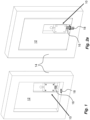
- Figs. 1 and 2 schematically shows such one example of a locking system 10 attached to a swing door 12, in turn pivotally attached to a door frame or post 14 of a compartment (not shown).
- the locking system 10 comprises a locking member 8 in the form of a locking bolt 16 that is movable in the longitudinal direction between a retracted resting position and an extended locking position.
- a locking system In the locking position, the free end of the locking bolt 16 is inserted into a recess 18 in a fixed structure such as the door frame as seen in the right picture in Fig. 2a . It is to be understood that the locking system may be placed in other positions on a door.
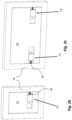
- Figure 2b shows a locking system on one side of a door
- Fig. 2c shows two locking systems, one on each side of a door. It is also to be understood that a locking system may act upwards.
- locking member may include bolts, latches, bars, pins and all types of members that are capable of engaging with fixed structures for providing a locking action, and combinations of these as well as locking systems having a plurality of cooperating locking members such as espagnolettes and other transmissions such as in safe doors operating several locking members at the same time, which locking members may engage with fixed structures in different directions and may be moved from a resting position to a locking position. The movement may be performed by different means such as handles, transmissions and combinations thereof as well as by the movement of the door that is to be locked and also by manually moving the locking member.
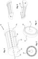
- a first example of a device 20 to be used with a locking member 8 is shown in Figs. 3 to 6 .
- the device comprises a number of generally plate-shaped elongated wear-resistant elements 22.
- the wear-resistant elements 22 extend generally along a centre axis CA.
- the wear-resistant elements 22 are made of very hard material that is highly resistant to physical wear such as from a grinder with a cutting wheel, a reciprocating saw or the like tools.
- the material of the wear-resistant elements may comprise metallic carbide, either mixed with some binding material or be completely of carbide.
- metallic carbides may be used, such as for instance tungsten carbide and titanium carbide. It is however to be understood that other carbides may be utilized.
- the wear-resistant elements 22 are attached to a support structure 24.
- the support structure 24 comprises two end plates 24 1 and 24 2 .
- Each end plate 24 1 and 24 2 is arranged with a circumferential groove 26 as well as a central passage 27.
- the width of the groove 26 generally corresponds to the thickness of the wear-resistant elements 22.
- a section of a locking member When used for a locking member, a section of a locking member, such as a drive rod of a locking bolt, may extend along the centre axis CA through the passages 27 of the end plates as well as through the cavity 28, where the wear-resistant elements 22 form a very secure protection against any attempts to cut off the locking member.
- Fig. 6 shows that the end plates 24 1 and 24 2 may be made in two halves in order to facilitate assembly of the device and/or attachment to a section of a locking member but also if there is a need to protect only one side of a locking member.
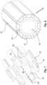
- FIG. 7 and 8 Another example shown in Figs. 7 and 8 , comprises a support structure 24'.
- the support structure 24' is elongated and with a generally cylindrical form.
- the support structure 24' is provided with a cavity 28 that extends from one end of the support structure to the other, having a centre axis CA.
- the cavity 28 is in the embodiment of Figs. 7 and 8 generally cylindrical but may have other shapes as will be apparent.
- the cavity 28 is arranged with at least one opening 30 in at least one of the ends.
- wear-resistant elements 22 are arranged to be attached to the support structure 24'. As shown in Figs. 7 and 8 , the wear-resistant elements 22 are designed as discrete plate-formed members with generally rectangular shape and with a certain thickness. The wear-resistant elements 22 extend a certain length along the support structure 24' and generally parallel with the centre axis CA.
- the wear-resistant elements 22 are in the embodiments shown attached to carrier structures 32.
- the attachment may be obtained with several solutions such as suitable bonding between them, for instance by welding such as TiG-welding, induction welding etc.
- the carrier structures 32 are in the embodiment designed as elongated rods with a certain thickness and a length generally corresponding to the length of the support structure 24'.
- the carrier structures 32 have an outwardly generally planar surface onto which the wear-resistant elements 22 are attached.
- the carrier structures 32 are further attached to the support structure 24'. This attachment may be made in several ways. According to the variant of Figs. 7 and 8 , the carrier structures 32 are arranged with a dove-tail shaped profile 34, as seen in a cross-section, on the opposite sides of the wear-resistant elements 22.
- the dove-tail profiles 34 are arranged to interact with longitudinal grooves 36, generally parallel with the centre axis of the support structure 24', on an outer circumferential surface of the support structure 24'.
- the grooves 36 have complementary dove-tailed shapes as seen in a cross-section.
- the dove-tail profiles 34 are entered into the dove-shaped grooves 36 at one end of the support structure 24' and are slid into the correct position as seen in Fig. 8 , forming a form-locking solution.
- the carrier structures 32 are then secured to the support structure by appropriate means. This may entail welding, bolting or any other suitable means.
- the assembled device 20 is now provided with outwardly facing very hard wear-resistant surfaces in the form of the wear-resistant elements 22, protecting any item placed inside the cavity 28 as well as the support structure 24', as will be described below.
- the grooves 36 on the outer surface of the support structure 24' may have other shapes in a cross-sectional view and thus the shapes of the carrier structures 32 are shaped correspondingly.
- the side walls 36' of the longitudinal grooves 36 are somewhat rounded and the side surfaces 32' of the carrier structures 32 as well, providing a complementary profile. This enables a good form-locking fixation of the carrier structures 32 to the support structure 24', when slid into the grooves 36.
- the carrier structures 32 are attached in an appropriate way to the support structure 24'.
- the support structure 22 may be arranged with recesses 38 or passages 40, Fig. 11 , to enable access for a welding gun such as a TiG torch to weld the carrier structures 32 to the support structure 22.
- the device as described above is intended to be arranged to surround and protect a locking member such as a pin or bolt 16 of a locking system 10, Figs. 1 and 2 , where the locking bolt 16 is arranged to move in a longitudinal direction from a retracted resting position, Fig. 1 , to an extended locking position, Fig. 2 , in which an outer end of the locking bolt 16 fits into a recess 18 of a fixed structure such as a door post 14, the walls and/or bottom/ceiling of a container, for instance a semi-trailer container or a body of a trailer or a vehicle.
- a locking member such as a pin or bolt 16 of a locking system 10
- Figs. 1 and 2 where the locking bolt 16 is arranged to move in a longitudinal direction from a retracted resting position, Fig. 1 , to an extended locking position, Fig. 2 , in which an outer end of the locking bolt 16 fits into a recess 18 of a fixed structure such as a door post
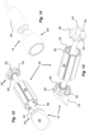
- Figs. 12 and 13 show a further example of the device 20 wherein a locking member in the form of a locking bolt 16 is shown together with the device 20.
- the locking bolt 16 has an elongated drive pin 42 and an outer end 44 that is to enter into a locking recess.
- the outer end 44 is arranged with a bevelled surface 46, enabling a movement in the longitudinal direction of the locking bolt 16 when the outer end 44 hits a fixed structure, thereby enabling an automatic locking function in that the locking bolt 16 is moved to a retracted position until the outer end is in alignment with a locking recess, whereby the locking bolt 16 is moved to an extended locking position by appropriate force means, such as springs acting on the locking bolt for biasing it into the extended position.
- Figs. 12 and 13 also has a number of wear-resistant elements 22 attached to carrier structures 32.
- the cross section of the carrier structures 32 shows rounded side surfaces.
- the support structure 24" comprises two end plates 48 having central passages 50 through which the drive pin 42 can pass.
- the surfaces of the end plates 48 facing each other are provided with a number of recesses or short grooves 52 having corresponding shapes to the cross-sectional shapes of the carrier structures 32 such that the ends of the carrier structures 32 may be pushed into and be held by the grooves 52 of the end plates 48, forming a form-locking unit of the device 20 with a central cavity 58.
- the ends of the carrier structures 32 are then fixedly attached to the end plates 48 by appropriate means.
- a number of through-holes 54 are shown in the end plates 48 as well as a number of holes 56 in the ends of the carrier structures 32, preferably threaded, wherein screws may be used to attach the carrier structures 32 to the end plates 48.
- This solution provides a secure protection of the locking bolt 16 from any attempts to cut it in order to gain access to a compartment.
- the end plates 48 may further be arranged with bearings 60 that are fixedly attached to each end plate 48, which for example could be by a press fit of the bearing 60 into a recess in the end plate 48.
- the central passages of the bearings 60 have such a diameter that generally correspond to the diameter of the drive pin 42 so that the drive pin 42 may pass through the bearings 60 of the device 20.
- the device 20 may now rotate easily around the drive pin 42, whereby any attempts to cut through the device by e.g.
- the bearings may be of many different types and designs depending on the desired function. As shown in Figs. 12 and 13 , the bearings 60 are ball bearings, providing a very low frictional rotation of the device. However, it is to be understood that for example roller bearings or sliding bearings may be used for providing the rotational movement in relation to the locking pin.
- an outer cylindrical sleeve 62 may be arranged surrounding the wear-resistant elements 22.
- the sleeve 62 may have an inner diameter such that the end plates 48 are press-fitted into the sleeve.
- the sleeve 62 may also be welded to the end plates 48 or attached by screws for instance.
- Figures 15 to 17 show a further variant of the device 20 according to the invention.
- the support structure 24′′′ is rectangular in cross-section and has a rectangular cavity 28.
- the outer side surfaces of the support structure 24′′′ is arranged with a number longitudinally extending grooves 34 in which carrier structures 32 are placed in the same manner as above.
- wear-resistant elements 22 are attached to the carrier structures 32.
- carrier structures 32 are arranged on the corners of the support structure 24"', forming a general L-shape in cross-section. On these L-shaped carrier structures, two wear-resistant elements are attached, instead of one wear-resistant element on each support structure.
- the carrier structures are held in position by a first and a second end plate 64, 66.
- the first end plate 64 has a rectangular recess 68, the side walls of which are arranged with short grooves 70 in which the carrier structures 32 and the wear-resistant elements 22 fit.
- the second end plate 66 is provided with a rectangular protrusion 72 with short grooves 70 on its outer surface in which the carrier structures 32 fit.
- the second end plate 66 is arranged with a locking element 73 such that the device forms the free end of the locking bolt.
- the end plates 64, 66 are for example forced towards each other, clamping the carrier structures, by a threaded rod (not shown) passing through the support structure 24′′′.
- Figures 18 to 20 show a further variant of the device for protecting a locking member.
- the support structure 24"" is made of a number of generally plate-shaped elements 74 that are attached to each other by suitable means such as welding such that the plate-shaped elements 74 extend radially from a centre point.
- carrier structures 32 are attached, for instance by welding.
- the plate-shaped members 74 may be formed with a T-shape and then attached to each other such that the carrier structure is integrated with the radially extending part of the plate-shaped members 74.
- wear-resistant elements 22 are attached.
- end plates 48' may be provided, arranged with short grooves 52' as mentioned above, in which the ends of the carrier structures 32 fit.
- the end plates 48' may also be provided with passages 51' in which the carrier structures fit 32.
- the end plates 48' may also be arranged with bearings to enable a rotation of the device.
- the end plates 48', with or without the bearings, may be provided with central shafts 76 that are connected and attached to further parts of the locking system.
- a device 20' may be used in other ways to protect a locking member such as a locking bolt 16 from access.
- Figs. 21-23 show an alternative device 20' in that respect.
- a support structure 100 is arranged as a hollow cylinder with a central cylindrical cavity 102 and having a certain wall thickness.
- a number of longitudinally extending grooves 104 are arranged on the inner wall of the cavity 102.
- the walls of the grooves are generally planar, where the transition between the walls may be rounded as seen in the figure or be square.
- the carrier structures 32 are arranged as longitudinal rods having a profile in cross-section generally corresponding to the grooves 104 on the inner wall.
- the carrier structures 32 are then, with the wear-resistant elements 22, attached to the support structure 100 as mentioned above.
- an end lid 106 may be used to secure the carrier structures as seen in Fig. 23 .
- This solution now forms a central cavity 108 having the wear-resistant elements 22 as inner surfaces of the cavity. It is to be noted in Figs. 22 and 23 , that the carrier structures 32 have not yet been fully pushed into the support structure in order for ease of understanding.
- the device 20' is to be attached to a fixed structure of a compartment, which could be by appropriate fixtures or by placing the device in a suitable recess in the fixed structure.
- the device 20' acts as a receiving part of a locking system such that the free or outer end 44 of the locking bolt 16 enters the central cavity 102 of the device and is protected by the wear-resistant elements 22 surrounding it. This is partly shown in Fig. 14 where a locking bolt is about to enter a device 20'.
- the device 20' may for example extend a distance from a surface of the fixed structure, such as for example the bottom of a container compartment, so that the device protects the locking bolt if for example a cutting tool was inserted in a gap between the bottom and a lower edge of a door closing the compartment.
- the solution with end plates may be utilized also for this use of the device 20' as shown in Fig. 24 .
- the end plates 48" are arranged with the same type of short grooves 52" into which the carrier structures 32 fit and are held.
- the carrier structures 32 are then fixedly attached to the end plates 48" by appropriate means, such as by screwing, forming a central cavity 24.
- one end plate 48' may be arranged with a central passage 50" through which the free end of the locking bolt may pass.
- Fig. 25 shows one example where the device 20 is used to protect a locking bolt both as a part attached to and surrounding an exposed section of the locking bolt as well as surrounding a free end of the locking bolt that has entered a fixed structure.
- the device is scalable such that it may have a longer extension along the locking member, and in particular if the device forms an integral part of the locking member.
- the device may also have a larger width or diameter as well as having other cross-sectional shapes than circular or rectangular, such as e.g. polygonal or oval, without departing from the inventive idea.
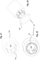
- a device for a locking member 8 is shown in Figs. 26 and 27 .
- a number of devices 20, such as for instance those described in connection with Figs. 18 to 20 are arranged in parallel with each other and may be placed in a surrounding housing 202 of the locking member 8.
- the housing 202 shown has a generally rectangular cross-section but may have a number of different shapes as desired.
- One end of the devices may be attached to a post 204.
- the post 204 is arranged with a shaft or attachment bolt 206.
- the attachment bolt is intended to be bolted onto a first door of an enclosure, such as for example back doors of a vehicle container.
- the attachment bolt 206 is surrounded and protected by a device 20 according to above, which may be provided with bearings as described.
- the opposite end of the locking member is arranged with a compartment 208 having a first opening 210 facing the same direction as the attachment bolt 206.
- the first opening 210 may be provided with a protective sleeve 212.
- One side of the compartment 208 is further arranged with a second opening 214.
- a locking U-bolt or the like (not shown) is bolted onto a second door of the enclosure, positioned adjacent the first door. The U-bolt will enter the first opening 210 with the sleeve 212 and be placed inside the compartment 208. Then a pad lock or the like (not shown) may then be inserted into the second opening 214 and engage with and lock with the U-bolt.
- the device according to the invention now protects the locking member from being cut by the devices inside the surrounding housing as well as surrounding the attachment bolt.
- the post 204 and the compartment 208 may be covered with plate-shaped wear-resistant elements 22.
- the locking member according to Figs. 26-27 may of course by used for a single door where one end of the locking member is attached to a fixed structure such as a wall of a compartment, and the other end is attached to the door.
- the concept is scalable in many ways. For instance, more or fewer devices may be arranged in parallel depending on the desired resistance. Also, the diameter of the devices may be decreased or increased depending on desired resistance and/or available space.
- the devices may be placed in a rectangle as shown in Fig. 28 .
- four devices have been used but it is of course to be understood that even more devices can be arranged, such as for example five as shown in Fig. 29 . As seen, the combinations are numerous.
- the length of the devices is also scalable. For instance, the devices may be made with the same length as vertical rods used in container locks or in espagnolettes.
- locking member with the device may be used interconnected with a transmission such in safes, where locking members may have different directions, whereby, if for example arranged in a safe door, a locking action may be obtained in up to four directions with locking members extending through some or all four sides of a door.
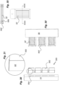
- Figs. 30-31 show a further variant of a device for a locking member wherein the device forms the locking member.
- the device 300 comprises plate-shaped elements acting as support structures 302.
- the support structure 302 of the device 300 may be inserted into and attached to a side of for example a swinging door 12, and in particular to the side where the hinges are attached.
- the support structure 302 is extending a distance from the side of the door.
- the exposed parts of the support structure 302 are covered with wear-resistant plate-shaped elements 22'. Further, the exposed parts are arranged to fit into cavities 304 in a fixed structure surrounding the door, such as a door frame 14 or other fixed structure enclosing a compartment.
- the locking member with the device 300 will be moved from a resting position when the door is open to a locking position when the exposed parts fit into the cavities 304.
- the wear-resistant elements 22' will effectively prevent any attempts to cut the locking member in the gap between the door and the fixed structure.
- the door cannot be opened due to the locking members.
- several locking members may be arranged along the side of the door, to make it even harder to forcibly open the door by any tools.
- Figs. 32-33 show a modification of the device of Figs. 30-31 .
- the support structure 302' is arranged as a generally rectangular frame provided with longitudinal grooves 306.
- strips of plate-shaped wear-resistant elements 22' are positioned and attached as seen in Fig. 31 .
- the device is for the rest intended to be used in the same manner as the device of Figs. 30-31 .
Landscapes
- Connection Of Plates (AREA)
- Aiming, Guidance, Guns With A Light Source, Armor, Camouflage, And Targets (AREA)
- Fire Alarms (AREA)
- Casings For Electric Apparatus (AREA)
Claims (15)
- Vorrichtung (20) zum Schützen mindestens eines Abschnitts eines zwischen einer Ruheposition und einer Verriegelungsposition beweglichen Verriegelungselements, umfassend- eine Stützstruktur (24);- eine Vielzahl plattenförmiger verschleißfester Elemente (22), die an der Stützstruktur angebracht sind;- wobei sich die verschleißfesten Elemente allgemein in der Richtung erstrecken, die mit dem Verriegelungselement zusammenfällt, und wobei- die verschleißfesten Elemente Karbidmaterial umfassen- wobei die verschleißfesten Elemente (22) so angeordnet sind, dass sie einen Hohlraum (28, 108) mit mindestens einer Öffnung bilden, in dem der mindestens eine Abschnitt des Verriegelungselements positioniert werden kann.
- Vorrichtung nach Anspruch 1, wobei die Stützstruktur (24) mit den verschleißfesten Elementen den Hohlraum bildet.
- Vorrichtung nach Anspruch 1 oder 2, wobei die verschleißfesten Elemente (22) an Trägerstrukturen (32) angebracht sind.
- Vorrichtung nach Anspruch 3, wobei die Trägerstrukturen an der Stützstruktur angebracht sind.
- Vorrichtung nach Anspruch 4, wobei die Trägerstrukturen an einer nach außen gerichteten Oberfläche der Stützstruktur angebracht sind, wobei die verschleißfesten Elemente nach außen weisen.
- Vorrichtung nach Anspruch 5, wobei die Trägerstrukturen an einer nach innen gerichteten Oberfläche der Stützstruktur angebracht sind, wobei die verschleißfesten Elemente in Richtung des Hohlraums weisen.
- Vorrichtung nach einem der Ansprüche 3 bis 6, wobei die Stützstruktur (24) eine Anzahl von Nuten umfasst, die sich allgemein in der Richtung erstrecken, die mit dem Verriegelungselement zusammenfällt, wobei die Trägerstruktur einen Steg umfasst, der so gestaltet ist, dass er in eine Nut passt, und wobei die Nuten und die Stege Profile derart aufweisen, dass eine Formschlussfunktion erhalten wird.
- Vorrichtung nach Anspruch 7, wobei die Nuten eine Schwalbenschwanzform aufweisen und wobei die Stege der Trägerstrukturen Schwalbenschwanzstege umfassen, die so gestaltet sind, dass sie in die Schwalbenschwanznuten der Stützstruktur passen.
- Vorrichtung nach Anspruch 5, wobei die Stützstruktur (24) Stirnplatten (241, 242, 64, 66, 48, 48', 48") umfasst, die zur Anbringung an den Enden der Trägerstrukturen gestaltet sind.
- Vorrichtung nach Anspruch 9, wobei mindestens eine der Stirnplatten (48) mit einem zentralen Durchgang (50) versehen ist, durch den ein Teil des Verriegelungselements durchgeführt werden kann.
- Vorrichtung nach Anspruch 10, wobei die Stirnplatten mit Lagern (60) versehen sind, die eine Drehbewegung der Vorrichtung um den Teil des Verriegelungselements ermöglichen.
- Vorrichtung nach Anspruch 11, wobei es sich bei den Lagern um Kugellager oder Rollenlager handelt.
- Vorrichtung nach Anspruch 10, wobei ein freies Ende eines Verriegelungselements in eine der Stirnplatten integriert ist.
- Vorrichtung nach einem der vorhergehenden Ansprüche, wobei die Vorrichtung an dem Verriegelungselement angebracht ist.
- Verriegelungselement, das eine Vorrichtung nach einem der vorhergehenden Ansprüche 1 bis 14 umfasst.
Applications Claiming Priority (2)
| Application Number | Priority Date | Filing Date | Title |
|---|---|---|---|
| SE2050402 | 2020-04-08 | ||
| PCT/EP2021/058915 WO2021204785A1 (en) | 2020-04-08 | 2021-04-06 | Security device |
Publications (3)
| Publication Number | Publication Date |
|---|---|
| EP4133150A1 EP4133150A1 (de) | 2023-02-15 |
| EP4133150C0 EP4133150C0 (de) | 2024-05-15 |
| EP4133150B1 true EP4133150B1 (de) | 2024-05-15 |
Family
ID=75478020
Family Applications (1)
| Application Number | Title | Priority Date | Filing Date |
|---|---|---|---|
| EP21718063.7A Active EP4133150B1 (de) | 2020-04-08 | 2021-04-06 | Sicherheitsvorrichtung |
Country Status (3)
| Country | Link |
|---|---|
| EP (1) | EP4133150B1 (de) |
| WO (1) | WO2021204785A1 (de) |
| ZA (1) | ZA202301604B (de) |
Family Cites Families (6)
| Publication number | Priority date | Publication date | Assignee | Title |
|---|---|---|---|---|
| GB1392268A (en) * | 1973-10-15 | 1975-04-30 | Shwayder W M | Saw and impact resistant members and methods of making such members |
| GB8514919D0 (en) | 1985-06-12 | 1985-07-17 | Chubb Security Installations | Security bars |
| GB8719600D0 (en) | 1987-08-19 | 1987-09-23 | Directnext Ltd | Security members |
| GB2376262A (en) * | 2001-06-06 | 2002-12-11 | Secr Defence | Lock with drill resistant lock bolt member |
| GB2391898B (en) * | 2002-08-08 | 2006-05-17 | Laird Security Hardware Ltd | Locks |
| GB2559341B (en) * | 2017-01-31 | 2020-08-05 | Bja Trading Ltd | Throw lock assemblies, throw bolt assemblies, and methods for assembling and using same |
-
2021
- 2021-04-06 WO PCT/EP2021/058915 patent/WO2021204785A1/en not_active Ceased
- 2021-04-06 EP EP21718063.7A patent/EP4133150B1/de active Active
-
2023
- 2023-02-08 ZA ZA2023/01604A patent/ZA202301604B/en unknown
Also Published As
| Publication number | Publication date |
|---|---|
| EP4133150C0 (de) | 2024-05-15 |
| WO2021204785A1 (en) | 2021-10-14 |
| EP4133150A1 (de) | 2023-02-15 |
| ZA202301604B (en) | 2024-06-26 |
Similar Documents
| Publication | Publication Date | Title |
|---|---|---|
| US4095828A (en) | Locking assembly | |
| US8276527B2 (en) | Corner bolt locking system | |
| US3820360A (en) | High security hasp lock | |
| US7946142B2 (en) | Padlock hasp assembly | |
| US7770422B1 (en) | Round padlock | |
| EP2592203A2 (de) | Schloss | |
| AU2007201947A1 (en) | Dual lock locking system for containers | |
| EP1218611B1 (de) | Türverriegelungssystem für einen container | |
| EP4133150B1 (de) | Sicherheitsvorrichtung | |
| AU729899B2 (en) | A locking device | |
| US5035127A (en) | Lock arrangement for containers | |
| EP1713987B1 (de) | Sicherheitscontainer | |
| EP1662949A1 (de) | Verbesserungen bei und in bezug auf sicherheitsmittel(n) | |
| US20240318468A1 (en) | High Security Hasp for Hidden Shackle Lock | |
| US20250270870A1 (en) | Safe locking mechanisms and related apparatus | |
| WO1994015055A1 (en) | Locking device at safety lockers | |
| US20100244467A1 (en) | Device for locking at least one door element in an opening to a space | |
| US11180932B2 (en) | Theft deterrent system for electronics cabinet door | |
| US8201427B1 (en) | Lock housing | |
| US20020017520A1 (en) | External locking mechanism | |
| WO2003054331A1 (en) | A container lock device | |
| US20020020706A1 (en) | Internal locking mechanism | |
| EP4089252B1 (de) | Beschlag für ein zu öffnendes element | |
| CA1054819A (en) | Internal lock for trailer door | |
| WO2019004889A1 (en) | Locking device for cargo containers and method |
Legal Events
| Date | Code | Title | Description |
|---|---|---|---|
| STAA | Information on the status of an ep patent application or granted ep patent |
Free format text: STATUS: UNKNOWN |
|
| STAA | Information on the status of an ep patent application or granted ep patent |
Free format text: STATUS: THE INTERNATIONAL PUBLICATION HAS BEEN MADE |
|
| PUAI | Public reference made under article 153(3) epc to a published international application that has entered the european phase |
Free format text: ORIGINAL CODE: 0009012 |
|
| STAA | Information on the status of an ep patent application or granted ep patent |
Free format text: STATUS: REQUEST FOR EXAMINATION WAS MADE |
|
| 17P | Request for examination filed |
Effective date: 20221007 |
|
| AK | Designated contracting states |
Kind code of ref document: A1 Designated state(s): AL AT BE BG CH CY CZ DE DK EE ES FI FR GB GR HR HU IE IS IT LI LT LU LV MC MK MT NL NO PL PT RO RS SE SI SK SM TR |
|
| DAV | Request for validation of the european patent (deleted) | ||
| DAX | Request for extension of the european patent (deleted) | ||
| GRAP | Despatch of communication of intention to grant a patent |
Free format text: ORIGINAL CODE: EPIDOSNIGR1 |
|
| STAA | Information on the status of an ep patent application or granted ep patent |
Free format text: STATUS: GRANT OF PATENT IS INTENDED |
|
| INTG | Intention to grant announced |
Effective date: 20231207 |
|
| GRAS | Grant fee paid |
Free format text: ORIGINAL CODE: EPIDOSNIGR3 |
|
| GRAA | (expected) grant |
Free format text: ORIGINAL CODE: 0009210 |
|
| STAA | Information on the status of an ep patent application or granted ep patent |
Free format text: STATUS: THE PATENT HAS BEEN GRANTED |
|
| AK | Designated contracting states |
Kind code of ref document: B1 Designated state(s): AL AT BE BG CH CY CZ DE DK EE ES FI FR GB GR HR HU IE IS IT LI LT LU LV MC MK MT NL NO PL PT RO RS SE SI SK SM TR |
|
| REG | Reference to a national code |
Ref country code: CH Ref legal event code: EP |
|
| REG | Reference to a national code |
Ref country code: IE Ref legal event code: FG4D |
|
| REG | Reference to a national code |
Ref country code: DE Ref legal event code: R096 Ref document number: 602021013332 Country of ref document: DE |
|
| U01 | Request for unitary effect filed |
Effective date: 20240613 |
|
| U07 | Unitary effect registered |
Designated state(s): AT BE BG DE DK EE FI FR IT LT LU LV MT NL PT SE SI Effective date: 20240624 |
|
| PG25 | Lapsed in a contracting state [announced via postgrant information from national office to epo] |
Ref country code: IS Free format text: LAPSE BECAUSE OF FAILURE TO SUBMIT A TRANSLATION OF THE DESCRIPTION OR TO PAY THE FEE WITHIN THE PRESCRIBED TIME-LIMIT Effective date: 20240915 |
|
| PG25 | Lapsed in a contracting state [announced via postgrant information from national office to epo] |
Ref country code: HR Free format text: LAPSE BECAUSE OF FAILURE TO SUBMIT A TRANSLATION OF THE DESCRIPTION OR TO PAY THE FEE WITHIN THE PRESCRIBED TIME-LIMIT Effective date: 20240515 |
|
| PG25 | Lapsed in a contracting state [announced via postgrant information from national office to epo] |
Ref country code: GR Free format text: LAPSE BECAUSE OF FAILURE TO SUBMIT A TRANSLATION OF THE DESCRIPTION OR TO PAY THE FEE WITHIN THE PRESCRIBED TIME-LIMIT Effective date: 20240816 |
|
| PG25 | Lapsed in a contracting state [announced via postgrant information from national office to epo] |
Ref country code: ES Free format text: LAPSE BECAUSE OF FAILURE TO SUBMIT A TRANSLATION OF THE DESCRIPTION OR TO PAY THE FEE WITHIN THE PRESCRIBED TIME-LIMIT Effective date: 20240515 |
|
| PG25 | Lapsed in a contracting state [announced via postgrant information from national office to epo] |
Ref country code: PL Free format text: LAPSE BECAUSE OF FAILURE TO SUBMIT A TRANSLATION OF THE DESCRIPTION OR TO PAY THE FEE WITHIN THE PRESCRIBED TIME-LIMIT Effective date: 20240515 |
|
| PG25 | Lapsed in a contracting state [announced via postgrant information from national office to epo] |
Ref country code: PL Free format text: LAPSE BECAUSE OF FAILURE TO SUBMIT A TRANSLATION OF THE DESCRIPTION OR TO PAY THE FEE WITHIN THE PRESCRIBED TIME-LIMIT Effective date: 20240515 Ref country code: NO Free format text: LAPSE BECAUSE OF FAILURE TO SUBMIT A TRANSLATION OF THE DESCRIPTION OR TO PAY THE FEE WITHIN THE PRESCRIBED TIME-LIMIT Effective date: 20240815 Ref country code: IS Free format text: LAPSE BECAUSE OF FAILURE TO SUBMIT A TRANSLATION OF THE DESCRIPTION OR TO PAY THE FEE WITHIN THE PRESCRIBED TIME-LIMIT Effective date: 20240915 Ref country code: HR Free format text: LAPSE BECAUSE OF FAILURE TO SUBMIT A TRANSLATION OF THE DESCRIPTION OR TO PAY THE FEE WITHIN THE PRESCRIBED TIME-LIMIT Effective date: 20240515 Ref country code: GR Free format text: LAPSE BECAUSE OF FAILURE TO SUBMIT A TRANSLATION OF THE DESCRIPTION OR TO PAY THE FEE WITHIN THE PRESCRIBED TIME-LIMIT Effective date: 20240816 Ref country code: ES Free format text: LAPSE BECAUSE OF FAILURE TO SUBMIT A TRANSLATION OF THE DESCRIPTION OR TO PAY THE FEE WITHIN THE PRESCRIBED TIME-LIMIT Effective date: 20240515 Ref country code: RS Free format text: LAPSE BECAUSE OF FAILURE TO SUBMIT A TRANSLATION OF THE DESCRIPTION OR TO PAY THE FEE WITHIN THE PRESCRIBED TIME-LIMIT Effective date: 20240815 |
|
| PG25 | Lapsed in a contracting state [announced via postgrant information from national office to epo] |
Ref country code: CZ Free format text: LAPSE BECAUSE OF FAILURE TO SUBMIT A TRANSLATION OF THE DESCRIPTION OR TO PAY THE FEE WITHIN THE PRESCRIBED TIME-LIMIT Effective date: 20240515 |
|
| PG25 | Lapsed in a contracting state [announced via postgrant information from national office to epo] |
Ref country code: SK Free format text: LAPSE BECAUSE OF FAILURE TO SUBMIT A TRANSLATION OF THE DESCRIPTION OR TO PAY THE FEE WITHIN THE PRESCRIBED TIME-LIMIT Effective date: 20240515 Ref country code: RO Free format text: LAPSE BECAUSE OF FAILURE TO SUBMIT A TRANSLATION OF THE DESCRIPTION OR TO PAY THE FEE WITHIN THE PRESCRIBED TIME-LIMIT Effective date: 20240515 |
|
| PG25 | Lapsed in a contracting state [announced via postgrant information from national office to epo] |
Ref country code: SM Free format text: LAPSE BECAUSE OF FAILURE TO SUBMIT A TRANSLATION OF THE DESCRIPTION OR TO PAY THE FEE WITHIN THE PRESCRIBED TIME-LIMIT Effective date: 20240515 |
|
| PG25 | Lapsed in a contracting state [announced via postgrant information from national office to epo] |
Ref country code: SM Free format text: LAPSE BECAUSE OF FAILURE TO SUBMIT A TRANSLATION OF THE DESCRIPTION OR TO PAY THE FEE WITHIN THE PRESCRIBED TIME-LIMIT Effective date: 20240515 Ref country code: SK Free format text: LAPSE BECAUSE OF FAILURE TO SUBMIT A TRANSLATION OF THE DESCRIPTION OR TO PAY THE FEE WITHIN THE PRESCRIBED TIME-LIMIT Effective date: 20240515 Ref country code: RO Free format text: LAPSE BECAUSE OF FAILURE TO SUBMIT A TRANSLATION OF THE DESCRIPTION OR TO PAY THE FEE WITHIN THE PRESCRIBED TIME-LIMIT Effective date: 20240515 Ref country code: CZ Free format text: LAPSE BECAUSE OF FAILURE TO SUBMIT A TRANSLATION OF THE DESCRIPTION OR TO PAY THE FEE WITHIN THE PRESCRIBED TIME-LIMIT Effective date: 20240515 |
|
| REG | Reference to a national code |
Ref country code: DE Ref legal event code: R097 Ref document number: 602021013332 Country of ref document: DE |
|
| PLBE | No opposition filed within time limit |
Free format text: ORIGINAL CODE: 0009261 |
|
| STAA | Information on the status of an ep patent application or granted ep patent |
Free format text: STATUS: NO OPPOSITION FILED WITHIN TIME LIMIT |
|
| 26N | No opposition filed |
Effective date: 20250218 |
|
| U20 | Renewal fee for the european patent with unitary effect paid |
Year of fee payment: 5 Effective date: 20250415 |
|
| PGFP | Annual fee paid to national office [announced via postgrant information from national office to epo] |
Ref country code: GB Payment date: 20250422 Year of fee payment: 5 |
|
| REG | Reference to a national code |
Ref country code: CH Ref legal event code: H13 Free format text: ST27 STATUS EVENT CODE: U-0-0-H10-H13 (AS PROVIDED BY THE NATIONAL OFFICE) Effective date: 20251125 |
|
| PG25 | Lapsed in a contracting state [announced via postgrant information from national office to epo] |
Ref country code: MC Free format text: LAPSE BECAUSE OF FAILURE TO SUBMIT A TRANSLATION OF THE DESCRIPTION OR TO PAY THE FEE WITHIN THE PRESCRIBED TIME-LIMIT Effective date: 20240515 |
|
| PG25 | Lapsed in a contracting state [announced via postgrant information from national office to epo] |
Ref country code: CH Free format text: LAPSE BECAUSE OF NON-PAYMENT OF DUE FEES Effective date: 20250430 |