EP4132821B1 - An abs actuator device for a bicycle hydraulic braking system - Google Patents
An abs actuator device for a bicycle hydraulic braking system Download PDFInfo
- Publication number
- EP4132821B1 EP4132821B1 EP21717235.2A EP21717235A EP4132821B1 EP 4132821 B1 EP4132821 B1 EP 4132821B1 EP 21717235 A EP21717235 A EP 21717235A EP 4132821 B1 EP4132821 B1 EP 4132821B1
- Authority
- EP
- European Patent Office
- Prior art keywords
- actuator device
- floating member
- sealing ring
- chamber
- inner cavity
- Prior art date
- Legal status (The legal status is an assumption and is not a legal conclusion. Google has not performed a legal analysis and makes no representation as to the accuracy of the status listed.)
- Active
Links
Images


Classifications
-
- B—PERFORMING OPERATIONS; TRANSPORTING
- B60—VEHICLES IN GENERAL
- B60T—VEHICLE BRAKE CONTROL SYSTEMS OR PARTS THEREOF; BRAKE CONTROL SYSTEMS OR PARTS THEREOF, IN GENERAL; ARRANGEMENT OF BRAKING ELEMENTS ON VEHICLES IN GENERAL; PORTABLE DEVICES FOR PREVENTING UNWANTED MOVEMENT OF VEHICLES; VEHICLE MODIFICATIONS TO FACILITATE COOLING OF BRAKES
- B60T8/00—Arrangements for adjusting wheel-braking force to meet varying vehicular or ground-surface conditions, e.g. limiting or varying distribution of braking force
- B60T8/17—Using electrical or electronic regulation means to control braking
- B60T8/1701—Braking or traction control means specially adapted for particular types of vehicles
- B60T8/1706—Braking or traction control means specially adapted for particular types of vehicles for single-track vehicles, e.g. motorcycles
-
- B—PERFORMING OPERATIONS; TRANSPORTING
- B62—LAND VEHICLES FOR TRAVELLING OTHERWISE THAN ON RAILS
- B62K—CYCLES; CYCLE FRAMES; CYCLE STEERING DEVICES; RIDER-OPERATED TERMINAL CONTROLS SPECIALLY ADAPTED FOR CYCLES; CYCLE AXLE SUSPENSIONS; CYCLE SIDECARS, FORECARS, OR THE LIKE
- B62K19/00—Cycle frames
- B62K19/30—Frame parts shaped to receive other cycle parts or accessories
-
- B—PERFORMING OPERATIONS; TRANSPORTING
- B62—LAND VEHICLES FOR TRAVELLING OTHERWISE THAN ON RAILS
- B62L—BRAKES SPECIALLY ADAPTED FOR CYCLES
- B62L3/00—Brake-actuating mechanisms; Arrangements thereof
- B62L3/02—Brake-actuating mechanisms; Arrangements thereof for control by a hand lever
- B62L3/023—Brake-actuating mechanisms; Arrangements thereof for control by a hand lever acting on fluid pressure systems
Definitions
- the present invention relates, in general, to braking systems for bicycles and - in particular - relates to an ABS actuator device for a bicycle hydraulic braking system.
- the invention is applicable to any type of bicycle, including bicycles assisted by an electric motor.
- the application of the invention is not excluded to any other type of cycle, including motorcycles, or electric scooters.
- WO 2019 155371 A1 illustrates an ABS actuator device for a bicycle hydraulic braking system of the type indicated in the preamble of the attached claim 1.
- This known device comprises an actuator body, defining an inner cavity, and having an inlet opening and an outlet opening communicating with the inner cavity.
- a floating member is slidably mounted in this cavity, configured so as to define an upstream chamber within the cavity, communicating with the inlet opening, and a downstream chamber, communicating with the outlet opening.
- a main sealing ring is mounted on the floating member between said upstream chamber and said downstream chamber.
- the aforesaid inlet and outlet openings are arranged to be hydraulically connected to a pumping device associated with an actuator member of a bicycle brake (for example, a brake lever) and with a hydraulic device for actuating a bicycle brake (e.g. the hydraulic cylinder of the caliper of a disc brake), respectively.
- a pumping device associated with an actuator member of a bicycle brake (for example, a brake lever) and with a hydraulic device for actuating a bicycle brake (e.g. the hydraulic cylinder of the caliper of a disc brake), respectively.
- the floating member defines a passage for hydraulic communication between the upstream chamber and said downstream chamber and is provided with a valve member for controlling the hydraulic communication through this passage.
- the aforesaid actuator device also comprises an electric motor configured to control the position of the floating member within the cavity of the actuator body.
- the electric motor is inactive and the floating member is in an end position, in the direction of the downstream chamber, wherein the valve member of the floating member is in an open position of said passage. Therefore, during normal operation of the brake, the floating member remains in this end position and the fluid pumped by the brake lever can flow from the inlet opening to said outlet opening, through the passage left open by the aforesaid valve member, to then arrive at the brake caliper.
- the electric motor is activated (by an electronic controller that receives a signal indicating, for example, an incipient locking of the bicycle wheel) and commands a movement of the floating member in the direction of the upstream chamber and away from the aforesaid end position.
- the valve member is in a closed position, so that the communication between the upstream and downstream chambers is interrupted.
- the movement of the floating member in the direction of the upstream chamber generates an increase in the volume of the downstream chamber, which gives rise to a decrease in the pressure of the fluid supplied to the brake caliper and, consequently, to a decrease in the braking action, which allows locking of the wheel to be avoided.
- the valve member with which the floating member is provided to open the communication between the two chambers of the actuator device in the end position of the floating member consists of a body that is slidably mounted in an axial cavity of the floating member and subject to the action of a spring that tends to push it against a valve seat defined in the wall of the axial cavity of the body of the floating member.
- the passage controlled by said valve member, which connects the upstream chamber with the downstream chamber, is formed through the body of the floating member.
- the valve member has a rod extending through an axial hole of the floating member and protruding into the downstream chamber.
- the tip of the rod engages an abutment element carried by the body of the actuator device, so that the valve member is kept in a position spaced apart from its valve seat, against the action of the aforesaid spring.
- the actuator member of the known device has a relatively complex structure; it consists of a plurality of components and involves complex and expensive manufacturing and assembly operations, also taking into account the need to adopt relatively narrow manufacturing tolerances, in order to ensure correct and stable operation over time of the aforesaid valve member.
- the object of the present invention is to overcome the drawbacks of the prior art.
- the object of the invention is to produce an actuator device of the type indicated above which has a relatively simple structure that is easy and cheap to construct and assemble and, nevertheless, extremely efficient and reliable during use.
- the invention relates to an actuator device having the characteristics of the attached claim 1.
- the device according to the invention is mainly characterized in that:
- the communication passage formed through the body of the floating member which was provided in the known device described above, is completely eliminated. Consequently, the need to form said passage in such a way as to define a valve seat is also completely eliminated, as well as the valve member slidably mounted within an inner cavity of the body of the floating element and the spring associated therewith.
- the efficiency and reliability of use of the device are ensured, thanks to the fact that the main sealing ring is used as the valve member, and thanks to the fact that the wall of the inner cavity of the body of the actuator device and/or the sealing ring is shaped in such a way that in the end position of the floating member - in the direction of the downstream chamber - the main sealing ring is spaced apart from the wall of the inner cavity, so as to leave the communication free, through said annular gap, between the upstream chamber and the downstream chamber, so that there is no control effect of the braking force characteristic of ABS systems.
- the floating member is moved away from said end position, i.e.
- the main sealing ring enters into engagement with the wall of the inner cavity, interrupting the communication between the upstream chamber and the downstream chamber, and causing the ABS effect following the simultaneous increase in volume of the downstream chamber.
- the main sealing ring has a central annular portion mounted within a seat of the body of the floating member, and an outer elastically deformable circumferential lip, which engages with the wall of the inner cavity of the body of the actuator device when the floating member is moved away from said end position beyond a predetermined distance.
- the wall of said inner cavity has:
- the actuator device of the invention is provided with a solenoid valve configured to place in direct communication, when activated, the inlet opening of the actuator device with the outlet opening, in such a way that said solenoid valve can be controlled by an electronic control unit of the bicycle braking system to establish said communication each time that an operating anomaly of the actuator device is detected by said electronic control unit.
- a solenoid valve configured to place in direct communication, when activated, the inlet opening of the actuator device with the outlet opening, in such a way that said solenoid valve can be controlled by an electronic control unit of the bicycle braking system to establish said communication each time that an operating anomaly of the actuator device is detected by said electronic control unit.
- the actuator device of the invention is provided with a pressure sensor arranged to detect the pressure in said upstream chamber or in said downstream chamber, in such a way as to allow the electronic control unit of the braking system to have direct control over the pressure of the fluid.
- the electronic control unit may have a more direct control over the correct functioning of the braking system, and can intervene more promptly in the event of any malfunction that endangers the operation of the brake.
- the aforesaid inlet and outlet openings of the actuator device of the invention are arranged on opposite sides of the body of the actuator device, and are provided with respective connecting elements with outlets at 90 degrees with respect to the respective openings in the body of the actuator device.
- At least one of said connecting elements may be selectively oriented into different positions, in such a way that the two outlets of the connecting elements may both be, for example, oriented parallelly to the axis of the floating member of the actuator device, and both facing towards one end of the body of the actuator device or, for example, towards opposite ends of the body of the actuator device.
- the actuator device of the invention can be easily configured to have the inlet and outlet tubes - for the fluid - that leave the actuator device in any direction, which allows great flexibility in the choice of mounting position of the actuator device on the bicycle.
- the actuator device can be mounted vertically on one of the two arms of the front fork of the bicycle; adjacent to the caliper of a disc brake, with the tubes protruding from opposite ends; or it can be mounted at a distance from the brake, for example on the upper longitudinal tube of the bicycle frame (or even inside it), with the tubes for the fluid coming out from the front end of the body of the actuator device).
- the reference number 1 indicates - in its entirety - a bicycle including a braking system equipped with an ABS actuator device according to the invention.
- ABS is used according to its conventional meaning in the art, that is, with reference to an Anti-Blocking System configured to reduce the action of a brake on a wheel when, during braking, the wheel tends to lock up.
- Devices of this type have been widespread for a long time in the field of motor-vehicles, but for some years they have also found increasing application in the field of bicycles.
- the actuator device according to the invention which - in the attached drawings - is indicated with the reference number 2, has been conceived and developed by the Applicant with particular reference to the application on a bicycle, and has characteristics that make it particularly advantageous in the case of such an application.
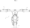
- the actuator device 2 is interposed in the hydraulic connection between a pumping device (not visible in the drawings) of any known type associated with the brake control member (for example, the lever 3 for actuating the front brake of the bicycle - see Figure 1 ) and an actuation device of the brake (for example, the hydraulic cylinder of the caliper 4 of a disc brake 5 - see Figure 2 ) associated with the front wheel of the bicycle.
- a pumping device not visible in the drawings
- the brake control member for example, the lever 3 for actuating the front brake of the bicycle - see Figure 1
- an actuation device of the brake for example, the hydraulic cylinder of the caliper 4 of a disc brake 5 - see Figure 2
- the actuator device 2 is configured in such a way as to leave ample flexibility in envisaging its positioning on the bicycle.
- it may be mounted on one of the two arms of the front fork of the bicycle, adjacent to the front disc brake controlled by it (also directly by means of the brake caliper support exploiting the same brake screws, see Figure 2 ), or, again for example, it may be mounted inside the upper longitudinal tube of the frame of the bicycle ( Figure 3 ), by providing a closed opening with a cover in the tube of the frame, or by providing mounting starting from one end of the frame tube, during manufacture and assembly of the frame.
- the actuator device 2 comprises a substantially elongated body 6 within which an inner cavity 7 is formed.
- the body 6 of the actuator device has an inlet opening 8 and an outlet opening 9, both communicating with the inner cavity 7, and formed on opposite sides of the body 6.
- the inlet and outlet openings 8, 9 are defined by holes directed radially and orthogonally with respect to the X-X axis of the body 6.
- the inlet opening 8 is intended to be connected, for example, by means of a flexible tube, to the pumping device controlled by the brake lever 3; while the outlet opening 9 is intended to be connected, for example, by means of a flexible tube, to the hydraulic cylinder actuator (not visible in the drawings) of the brake caliper 4.
- At least one of the connecting elements 10, 11 is selectively oriented into different positions, in such a way that the two outlets 12, 13 of the connecting elements may both be oriented, for example, parallelly to the X-X axis of the actuator device, and both facing towards one end of the body of the actuator device or towards opposite ends of the body of the actuator device.
- the actuator device of the invention can be easily configured to have the inlet and outlet tubes of the fluid that come out from the same end of the body of the actuator device, or from opposite ends, which allows great flexibility in the choice of mounting position of the actuator device on the bicycle.
- the actuator device 2 may be mounted vertically on one of the two arms of the front fork of the bicycle ( Figure 2 ); adjacent to the caliper 4 of the disc brake 5, with the tubes protruding in opposite directions; or it can be mounted at a distance from the brake, for example, inside the upper longitudinal tube of the bicycle frame ( Figure 3 ), with the tubes for the fluid both coming out from the front end in the same direction.
- a floating member 14 is slidably mounted within the inner cavity 7 of the body 6, said floating member having an elongated cylindrical body, with a portion 14A of larger diameter, which defines - inside the cavity 7- two chambers whose volume varies according to the position of the floating member: an upstream chamber 15, communicating with the inlet opening 8 (and consequently, in the condition of use, with the outlet of the pumping device operated by the brake lever 3), and a downstream chamber 16, communicating with the outlet opening 9 (and consequently, in the aforesaid condition of use, with the inlet of the hydraulic cylinder of actuation of the brake caliper 4).
- the chamber 16 is more clearly visible in Figure 4B , since in the position of the floating member 14 illustrated in Figure 4A (i.e. the end position towards the right, looking at the figures), the chamber 16 is in its minimum volume condition.
- the larger diameter portion 14A of the floating member 14 has a reduced diameter with respect to the diameter of the corresponding portion of the cavity 7 within which the portion 14A slides, to such an extent as to define an annular gap G that constitutes a communication passage between the two chambers 15,16.
- the communication passage between the two chambers 15, 16, consisting of the annular gap G defined between the outer surface of the floating member 14 and the wall of the cavity 7, is controlled by a valve member consisting of an main sealing ring 17 associated with the floating body 14.
- the sealing ring 17 is mounted in a circumferential groove of the portion 14A of the floating member 14.
- the sealing ring can be made of any elastomeric material suitable for the purposes indicated here.
- the wall of the inner cavity 7 of the body 6 of the actuator device and/or the main sealing ring 17 are configured in such a way that:
- the main sealing ring 17 (see Figure 5A ) has a central annular portion 171 mounted in the seat of the body of the floating member 14, and an outer elastically deformable circumferential lip 170, which engages with the wall of the inner cavity 7 of the body of the actuator device ( Figure 4B ) when the floating member 14 is moved away from said end position corresponding to a minimum volume of the downstream chamber 16.
- the wall of said inner cavity 7 preferably has (see Figure 5A ):
- the enlarged diameter portion 70 of the cavity 7 is axially extended for a minimum length, and is connected on both sides by means of tapered surfaces with both the adjacent reduced diameter portions of the cavity 7, within which the portion 14A of the floating member slides.
- the enlarged diameter portion 70 of the cavity 7 has a non-negligible axial extension, so as to define a portion of a cylindrical cavity 70.
- the cylindrical cavity portion 70 on one side, is connected by means of the tapered surface portion 72 with the reduced diameter portion 71 of the cavity 7. On the other side, the cylindrical surface portion 70 forms a step with respect to the adjacent reduced diameter portion of the cavity 7.
- Figure 5C shows another variant, wherein the enlarged diameter portion 70 of the cavity 7 has a single conical configuration, so that it also fulfills the function of the aforesaid tapered surface 72.
- Figures 5A-5C show only three embodiment examples, as it is understood that the cavity 7 could have any different shape which - in any case - ensures the operation described above, i.e. so that in the end position of the floating member 14 - in the direction of the downstream chamber 16 - the sealing ring leaves the communication free through the gap G, while when the floating member is moved away from this position, the sealing ring engages the wall of the cavity 7 and blocks the aforesaid communication.
- the floating member may have a solid body, without an inner passage formed through said body for communication between the two chambers, without a valve member slidably mounted inside the body of the floating member and without a spring associated with the valve member.
- Figure 4C shows a variant of Figure 4A , which refers to the case wherein the sealing ring 17 consists of a conventional O-ring type.
- the floating element 14 has a portion of enlarged diameter wherein the circumferential groove that receives the sealing ring 17 is formed, so that the sealing ring 17 can be supported on both sides by properly sized shoulders.
- the actuator device 2 comprises an electric motor M configured to control the axial position of the floating member 14 within the cavity 7 of the body 6.
- the electric motor is mounted coaxially to one end of the body 6 of the actuator device.
- the actuator body has three portions 6A, 6B and 6C arranged axially in series and rigidly connected to each other, for example, by screws.
- the portion 6A contains the components of the hydraulic system of the actuator device that have been described above.
- the portion 6B is in the form of a tube and constitutes an extension element to which the portion 6C is secured, in the form of a ring, to which the body of the electric motor M is, in turn, secured.
- the electric motor M has a crankshaft 26, which is connected in rotation with a screw 27 arranged coaxially with the floating member 14.
- the screw 27 is rotatably mounted within the body portion 6C by means of a rolling bearing 28 and is held by the bearing 28 (in the manner which will be described in detail below) in a fixed axial position.
- the screw 27 is engaged within the inner thread of a nut 29, which is guided within the portion 6B so as to be free to slide axially, but prevented from rotating. In this way, the nut 29 moves axially due to a rotation of the screw 27.
- the nut 29 is rigidly connected to the floating member 14. Therefore, thanks to the arrangement described above, the electric motor M is able to control the axial position of the floating member 14.
- the electric motor M is activated in such a way as to control a movement of the floating member 14 and of its portion 14A in the direction of the upstream chamber 15, and away from said end position, so that the main sealing ring enters into engagement with the wall of the inner cavity 7, interrupting the communication through the annular gap between the upstream chamber 15 and the downstream chamber 16.
- downstream chamber 16 increases in volume, generating a decrease in the pressure of the fluid supplied to the brake caliper 4 and, consequently, a decrease in the braking action that allows locking of the wheel to be avoided.
- the request for intervention of the ABS may be generated by an electronic control unit of the braking system, which is configured to receive signals from one or more sensors indicative of the operating conditions of the bicycle (for example, from an angular speed sensor of the wheel), and which is programmed to control the electric motor as a function of these signals, when they are indicative of an incipient locking of the wheel following braking.
- an electronic control unit of the braking system which is configured to receive signals from one or more sensors indicative of the operating conditions of the bicycle (for example, from an angular speed sensor of the wheel), and which is programmed to control the electric motor as a function of these signals, when they are indicative of an incipient locking of the wheel following braking.
- the actuator device 2 is arranged to open the communication between the upstream chamber 15 and the downstream chamber 16 when the pressure in the downstream chamber 16 becomes greater than the pressure in the upstream chamber, by a differential greater than a predetermined threshold.
- the outer circumferential lip 170 of the main sealing ring 17 extends in a cantilevered manner from said central portion 171 towards the upstream chamber 15, in such a way that when the circumferential lip 170 is in engagement against the wall of the reduced diameter portion 71 of the inner cavity 7 it is, however, able to deform elastically following an increase in pressure in the downstream chamber 16 with respect to the upstream chamber 15, so as to re-establish communication through said annular gap G, and equalize the pressure in the two aforesaid upstream and downstream chambers 15, 16.
- the actuator device 2 is provided with a solenoid valve 30 ( Figures 6-8 ) configured, when activated, to place the inlet opening 8 of the actuator device into direct communication with the outlet opening 9.
- the solenoid valve 30 may be controlled by an electronic control unit of the bicycle braking system to establish said communication whenever an operating anomaly of the actuator device is detected by the electronic control unit, for example, when the floating member remains erroneously locked in an ABS activation position, i.e. in a position such as that illustrated in Figure 4B . This provides additional safety that the braking system is always able to operate correctly, ensuring braking capability.
- the provision of the safety solenoid valve eliminates the need, provided in devices of the prior art, of a reversible transmission between the electric motor and the floating member, such as to allow, if the floating member stops due to a fault, the fluid pressure generated by the brake lever to be able to move the floating member backwards.
- the adoption of a reversible transmission requires stringent quality controls and the use of an expensive production screw.
- Figures 6-8 refer to an embodiment that is constructionally slightly different from that of Figure 4 (for example, regarding the positioning of the inlet and outlet openings 8, 9), but similar in substance.
- Figure 6 the parts corresponding to those of Figures 4 are indicated by the same reference numbers.
- the solenoid valve 30 includes a solenoid 31 that controls a slide valve member 32, slidably mounted in a cylindrical cavity 33 formed in the body 6 of the actuator device 2 parallel to and at a distance from the cavity 7, within which the floating member 14 is slidably mounted.
- the slide member 32 has a circumferential groove 37 which - in the position illustrated - intercepts the ends of two ducts 34, 35 formed in the body 6 and communicating, respectively, with the inlet and outlet openings 8, 9 (the cross-section of Figure 7 is taken in two radial planes with respect to the axis of the cavity 33, forming an angle of less than 90° between them).
- a helical spring 36 normally keeps the slide member 32 in an end position, wherein the groove 37 is axially spaced apart from the ends of the ducts 34, 35, so there is no communication between these ducts.
- the electronic unit When the electronic unit detects an anomalous situation that requires the solenoid, it activates the solenoid 31 to attract the slide member 32 into the position illustrated in the drawings, against the action of the spring 36, so as to establish communication between the ducts 34, 35 and, consequently, between the inlet and outlet openings 8, 9 of the actuator device.
- the braking system is able to operate correctly, ensuring that the fluid can pass from the pumping device operated by the brake lever 3, up to the brake caliper 4, passing through the actuator device 2.
- the actuator device 2 provides, as indicated above, a screw-and-nut transmission 27, 29 (see Figure 4 ) between the electric motor M and the floating member 14.
- this transmission includes a screw 27 rotatably mounted by means of a rolling bearing 28 within the body of the actuator device, and axially locked with respect to said rolling bearing.
- the screw 27 is connected in rotation with the shaft 26 of the electric motor M by means of a bushing 38.
- the bushing 38 has a bell-shaped conformation, with an axial hole having a first shaped portion 39 (in the example, square) for shape-coupling with the crankshaft 26, which has a corresponding shaped conformation.
- the aforesaid axial hole of the bushing 38 has a second shaped portion 40 (in the example, square), wider than the section 39 for shape-coupling with an end nose 27A of the screw 27, having a corresponding conformation.
- the axial hole of the bushing 39 opens into a shaped front cavity 41 (in the example hexagonal) for shape-coupling with a tightening nut 42, which is screwed onto a threaded portion of the end nose of the screw to lock the inner ring of the bearing 28 against an annular shoulder of the screw 27,
- the bushing 39 is secured in rotation both with the shaft 26 of the electric motor M and with the screw 27, and also with the tightening nut 42, so that any risk of loosening the nut 42 is safely prevented.
- the actuator device 2 is provided with a pressure sensor S P arranged to detect the pressure in the upstream chamber or, as in the case illustrated in the drawings, in the downstream chamber 16 (see Figures 4 , 11 ), in such a way as to allow the electronic control unit of the braking system to have a direct control over the fluid pressure.
- the electronic control unit may have a more direct control over the correct functioning of the braking system, and can intervene more promptly in the event of any malfunction that endangers the operation of the brake.
- the support body of the sensor S P is screwed into a seat formed in the body 6.
- the pressure signal output from the sensor S P is used by the electronic control unit to enable an ABS control logic, for example, according to an embodiment described in the Italian patent application IT 10 201 6000111289 .
- the sensor makes it possible to clearly identify when the cyclist is braking, precisely by means of the braking pressure signal. In this way, the control logic is more robust with respect to any false positives.
- the main sealing ring associated with the floating member constitutes the only valve member with which the floating member is provided to control the communication between the upstream and downstream chambers. Thanks to this arrangement, the actuator device according to the invention is constructively simple and extremely efficient, reliable and safe in operation.
Landscapes
- Engineering & Computer Science (AREA)
- Mechanical Engineering (AREA)
- Transportation (AREA)
- Physics & Mathematics (AREA)
- Fluid Mechanics (AREA)
- Regulating Braking Force (AREA)
Description
- The present invention relates, in general, to braking systems for bicycles and - in particular - relates to an ABS actuator device for a bicycle hydraulic braking system.
- The invention is applicable to any type of bicycle, including bicycles assisted by an electric motor. The application of the invention is not excluded to any other type of cycle, including motorcycles, or electric scooters.
- The document
WO 2019 155371 A1 illustrates an ABS actuator device for a bicycle hydraulic braking system of the type indicated in the preamble of the attachedclaim 1. - This known device comprises an actuator body, defining an inner cavity, and having an inlet opening and an outlet opening communicating with the inner cavity. A floating member is slidably mounted in this cavity, configured so as to define an upstream chamber within the cavity, communicating with the inlet opening, and a downstream chamber, communicating with the outlet opening. A main sealing ring is mounted on the floating member between said upstream chamber and said downstream chamber.
- The aforesaid inlet and outlet openings are arranged to be hydraulically connected to a pumping device associated with an actuator member of a bicycle brake (for example, a brake lever) and with a hydraulic device for actuating a bicycle brake (e.g. the hydraulic cylinder of the caliper of a disc brake), respectively.
- The floating member defines a passage for hydraulic communication between the upstream chamber and said downstream chamber and is provided with a valve member for controlling the hydraulic communication through this passage.
- The aforesaid actuator device also comprises an electric motor configured to control the position of the floating member within the cavity of the actuator body.
- During normal operation of the bicycle brake, the electric motor is inactive and the floating member is in an end position, in the direction of the downstream chamber, wherein the valve member of the floating member is in an open position of said passage. Therefore, during normal operation of the brake, the floating member remains in this end position and the fluid pumped by the brake lever can flow from the inlet opening to said outlet opening, through the passage left open by the aforesaid valve member, to then arrive at the brake caliper.
- Conversely, in conditions wherein the activation of the ABS is required, the electric motor is activated (by an electronic controller that receives a signal indicating, for example, an incipient locking of the bicycle wheel) and commands a movement of the floating member in the direction of the upstream chamber and away from the aforesaid end position. In this condition, the valve member is in a closed position, so that the communication between the upstream and downstream chambers is interrupted. At the same time, the movement of the floating member in the direction of the upstream chamber generates an increase in the volume of the downstream chamber, which gives rise to a decrease in the pressure of the fluid supplied to the brake caliper and, consequently, to a decrease in the braking action, which allows locking of the wheel to be avoided.
- In the aforesaid known device, the valve member with which the floating member is provided to open the communication between the two chambers of the actuator device in the end position of the floating member, consists of a body that is slidably mounted in an axial cavity of the floating member and subject to the action of a spring that tends to push it against a valve seat defined in the wall of the axial cavity of the body of the floating member. The passage controlled by said valve member, which connects the upstream chamber with the downstream chamber, is formed through the body of the floating member. The valve member has a rod extending through an axial hole of the floating member and protruding into the downstream chamber. In the aforesaid end position of the floating member, the tip of the rod engages an abutment element carried by the body of the actuator device, so that the valve member is kept in a position spaced apart from its valve seat, against the action of the aforesaid spring.
- As is evident, the actuator member of the known device has a relatively complex structure; it consists of a plurality of components and involves complex and expensive manufacturing and assembly operations, also taking into account the need to adopt relatively narrow manufacturing tolerances, in order to ensure correct and stable operation over time of the aforesaid valve member.
- The need is therefore felt for an actuator device that is simpler, cheaper and yet at least as efficient and reliable as the known device described above.
- The object of the present invention is to overcome the drawbacks of the prior art.
- More generally, the object of the invention is to produce an actuator device of the type indicated above which has a relatively simple structure that is easy and cheap to construct and assemble and, nevertheless, extremely efficient and reliable during use.
- In order to achieve this object, the invention relates to an actuator device having the characteristics of the attached
claim 1. - Compared to the known device described above, the device according to the invention is mainly characterized in that:
- the only valve member with which the actuator member is provided is constituted by said main sealing ring,
- the aforesaid passage that connects the upstream chamber with the downstream chamber is defined only by an annular gap between an outer surface of said floating member and the wall of said inner cavity of the actuator body,
- the wall of said inner cavity of the actuator body and/or said main sealing ring are configured in such a way that:
- in said end position of the floating member, the main sealing ring is spaced apart from the wall of the inner cavity, so as to leave free the
- communication, through said annular gap, between the upstream chamber and the downstream chamber, while
- when the floating member is moved away from said end position beyond a predetermined distance, said main sealing ring engages with the wall of said inner cavity, interrupting communication through said annular gap between the upstream chamber and the downstream chamber.
- As is evident, in the actuator device according to the invention, the communication passage formed through the body of the floating member, which was provided in the known device described above, is completely eliminated. Consequently, the need to form said passage in such a way as to define a valve seat is also completely eliminated, as well as the valve member slidably mounted within an inner cavity of the body of the floating element and the spring associated therewith.
- The construction and assembly of the device are, therefore, drastically simplified and the related cost is significantly reduced.
- At the same time, the efficiency and reliability of use of the device are ensured, thanks to the fact that the main sealing ring is used as the valve member, and thanks to the fact that the wall of the inner cavity of the body of the actuator device and/or the sealing ring is shaped in such a way that in the end position of the floating member - in the direction of the downstream chamber - the main sealing ring is spaced apart from the wall of the inner cavity, so as to leave the communication free, through said annular gap, between the upstream chamber and the downstream chamber, so that there is no control effect of the braking force characteristic of ABS systems. At the same time, when the floating member is moved away from said end position, i.e. it is moved in the direction of the upstream chamber for a distance greater than a predetermined distance, the main sealing ring enters into engagement with the wall of the inner cavity, interrupting the communication between the upstream chamber and the downstream chamber, and causing the ABS effect following the simultaneous increase in volume of the downstream chamber.
- In a preferred embodiment of the invention, the main sealing ring has a central annular portion mounted within a seat of the body of the floating member, and an outer elastically deformable circumferential lip, which engages with the wall of the inner cavity of the body of the actuator device when the floating member is moved away from said end position beyond a predetermined distance.
- Again in the case of this embodiment, the wall of said inner cavity has:
- a portion of enlarged diameter at the position taken by the main sealing ring when the floating member is in the aforesaid end position,
- a portion of reduced diameter at the position taken by the main sealing ring when the floating member is moved away from its end position, and
- a tapered portion connecting said portion of enlarged diameter to said portion of reduced diameter, which acts as an invitation surface to cause the necessary deformation of the main sealing ring when this must engage the wall of said portion of reduced diameter of the inner cavity following the moving away of the floating member from its end position.
- According to another characteristic, when the circumferential lip is engaged against the wall of the inner cavity it is - in any case - able to deform elastically following an increase in pressure in the downstream chamber with respect to the upstream chamber, so as to re-establish communication through said annular gap, and equalize the pressure in the aforesaid upstream chamber and downstream chamber.
- According to another aspect, which forms the object of the invention, even independently of the characteristics of the characterizing part of
claim 1, the actuator device of the invention is provided with a solenoid valve configured to place in direct communication, when activated, the inlet opening of the actuator device with the outlet opening, in such a way that said solenoid valve can be controlled by an electronic control unit of the bicycle braking system to establish said communication each time that an operating anomaly of the actuator device is detected by said electronic control unit. In this way, additional safety is obtained on the fact that the braking system is always able to operate correctly, ensuring the braking capacity. - According to yet another aspect, which also forms the object of the invention, even independently of the characteristics of the characterizing part of
claim 1, the actuator device of the invention is provided with a pressure sensor arranged to detect the pressure in said upstream chamber or in said downstream chamber, in such a way as to allow the electronic control unit of the braking system to have direct control over the pressure of the fluid. In this way, the electronic control unit may have a more direct control over the correct functioning of the braking system, and can intervene more promptly in the event of any malfunction that endangers the operation of the brake. - According to yet another aspect, which also forms the object of the invention, even independently of the characteristics of the characterizing part of
claim 1, the aforesaid inlet and outlet openings of the actuator device of the invention are arranged on opposite sides of the body of the actuator device, and are provided with respective connecting elements with outlets at 90 degrees with respect to the respective openings in the body of the actuator device. At least one of said connecting elements may be selectively oriented into different positions, in such a way that the two outlets of the connecting elements may both be, for example, oriented parallelly to the axis of the floating member of the actuator device, and both facing towards one end of the body of the actuator device or, for example, towards opposite ends of the body of the actuator device. Thanks to this characteristic, the actuator device of the invention can be easily configured to have the inlet and outlet tubes - for the fluid - that leave the actuator device in any direction, which allows great flexibility in the choice of mounting position of the actuator device on the bicycle. For example, the actuator device can be mounted vertically on one of the two arms of the front fork of the bicycle; adjacent to the caliper of a disc brake, with the tubes protruding from opposite ends; or it can be mounted at a distance from the brake, for example on the upper longitudinal tube of the bicycle frame (or even inside it), with the tubes for the fluid coming out from the front end of the body of the actuator device). - Further characteristics and advantages of the invention will become apparent from the description that follows with reference to the attached drawings, provided purely by way of non-limiting example, wherein:
-
Figure 1 is a partial top view of a bicycle using the ABS actuator device according to the invention, with the actuator device mounted inside the upper longitudinal tube of the bicycle frame, -
Figure 2 is a perspective view showing a detail of the front wheel of the bicycle ofFigure 1 , with the ABS actuator device mounted vertically on one of the two arms of the front fork of the bicycle, -
Figure 3 is a detail of a cross-sectioned side view of the bicycle ofFigure 1 , with the ABS actuator device mounted inside the upper longitudinal tube of the bicycle frame. -
Figure 4 is a cross-sectional view of an embodiment of the actuator device of the invention, illustrated in an operating condition of normal operation of the braking system, i.e. with inactive ABS, -
Figure 4A illustrates a detail on an enlarged scale ofFigure 4 , -
Figure 4B illustrates the detail ofFigure 4A in the ABS activation condition, -
Figure 4C is a variant ofFigure 4A . -
Figure 5A is a view, on an enlarged scale, of a detail ofFigure 4A , -
Figures 5B and 5C show two variants ofFigure 5A , -
Figure 6 is a partially cross-sectional view of another embodiment of the actuator device of the invention, which makes use of a safety solenoid valve to bypass the ABS actuator device in the event of a malfunction, -
Figure 7 is a cross-sectional view of the device ofFigure 6 , on an enlarged scale, -
Figure 8 illustrates a detail ofFigure 7 , in a further enlarged scale, showing the aforesaid by-pass solenoid valve, -
Figure 9 illustrates another detail on an enlarged scale ofFigure 4 , with reference to another aspect of the invention, -
Figure 10 is a perspective view of a component of the actuator device that is illustrated inFigure 9 , -
Figure 11 is a perspective view of a pressure sensor forming part of the actuator device ofFigure 4 , and -
Figures 12 and 13 are perspective views showing two alternative configurations of the actuator device according to the invention. - In the drawings, the
reference number 1 indicates - in its entirety - a bicycle including a braking system equipped with an ABS actuator device according to the invention. - In the present invention, the term ABS is used according to its conventional meaning in the art, that is, with reference to an Anti-Blocking System configured to reduce the action of a brake on a wheel when, during braking, the wheel tends to lock up. Devices of this type have been widespread for a long time in the field of motor-vehicles, but for some years they have also found increasing application in the field of bicycles.
- The actuator device according to the invention, which - in the attached drawings - is indicated with the
reference number 2, has been conceived and developed by the Applicant with particular reference to the application on a bicycle, and has characteristics that make it particularly advantageous in the case of such an application. - The drawings show, purely by way of example, some embodiments of the
actuator device 2 and its possible arrangements on the bicycle. In general, theactuator device 2 is interposed in the hydraulic connection between a pumping device (not visible in the drawings) of any known type associated with the brake control member (for example, thelever 3 for actuating the front brake of the bicycle - seeFigure 1 ) and an actuation device of the brake (for example, the hydraulic cylinder of thecaliper 4 of a disc brake 5 - seeFigure 2 ) associated with the front wheel of the bicycle. - As will be described in detail below, the
actuator device 2 is configured in such a way as to leave ample flexibility in envisaging its positioning on the bicycle. For example, it may be mounted on one of the two arms of the front fork of the bicycle, adjacent to the front disc brake controlled by it (also directly by means of the brake caliper support exploiting the same brake screws, seeFigure 2 ), or, again for example, it may be mounted inside the upper longitudinal tube of the frame of the bicycle (Figure 3 ), by providing a closed opening with a cover in the tube of the frame, or by providing mounting starting from one end of the frame tube, during manufacture and assembly of the frame. - With reference to
Figure 4 andFigure 4A , in the embodiment illustrated therein, theactuator device 2 comprises a substantiallyelongated body 6 within which aninner cavity 7 is formed. Thebody 6 of the actuator device has aninlet opening 8 and an outlet opening 9, both communicating with theinner cavity 7, and formed on opposite sides of thebody 6. In the example illustrated, the inlet andoutlet openings 8, 9 are defined by holes directed radially and orthogonally with respect to the X-X axis of thebody 6. - Two connecting
elements outlets openings 8, 9, i.e. oriented parallelly to the X-X axis, are associated with the inlet andoutlet openings 8, 9. Theinlet opening 8 is intended to be connected, for example, by means of a flexible tube, to the pumping device controlled by thebrake lever 3; while the outlet opening 9 is intended to be connected, for example, by means of a flexible tube, to the hydraulic cylinder actuator (not visible in the drawings) of thebrake caliper 4. - As is also visible in
Figures 12 and 13 , at least one of the connectingelements outlets - Thanks to this characteristic, the actuator device of the invention can be easily configured to have the inlet and outlet tubes of the fluid that come out from the same end of the body of the actuator device, or from opposite ends, which allows great flexibility in the choice of mounting position of the actuator device on the bicycle. For example, as already indicated above, the
actuator device 2 may be mounted vertically on one of the two arms of the front fork of the bicycle (Figure 2 ); adjacent to thecaliper 4 of thedisc brake 5, with the tubes protruding in opposite directions; or it can be mounted at a distance from the brake, for example, inside the upper longitudinal tube of the bicycle frame (Figure 3 ), with the tubes for the fluid both coming out from the front end in the same direction. - With reference again to
Figures 4 and4A , a floatingmember 14 is slidably mounted within theinner cavity 7 of thebody 6, said floating member having an elongated cylindrical body, with aportion 14A of larger diameter, which defines - inside the cavity 7- two chambers whose volume varies according to the position of the floating member: anupstream chamber 15, communicating with the inlet opening 8 (and consequently, in the condition of use, with the outlet of the pumping device operated by the brake lever 3), and adownstream chamber 16, communicating with the outlet opening 9 (and consequently, in the aforesaid condition of use, with the inlet of the hydraulic cylinder of actuation of the brake caliper 4). Thechamber 16 is more clearly visible inFigure 4B , since in the position of the floatingmember 14 illustrated inFigure 4A (i.e. the end position towards the right, looking at the figures), thechamber 16 is in its minimum volume condition. - The
larger diameter portion 14A of the floatingmember 14 has a reduced diameter with respect to the diameter of the corresponding portion of thecavity 7 within which theportion 14A slides, to such an extent as to define an annular gap G that constitutes a communication passage between the twochambers - The communication passage between the two
chambers member 14 and the wall of thecavity 7, is controlled by a valve member consisting of anmain sealing ring 17 associated with the floatingbody 14. In the example, the sealingring 17 is mounted in a circumferential groove of theportion 14A of the floatingmember 14. The sealing ring can be made of any elastomeric material suitable for the purposes indicated here. - With reference to the detail on an enlarged scale that is illustrated in
Figure 5A , according to the invention, the wall of theinner cavity 7 of thebody 6 of the actuator device and/or themain sealing ring 17 are configured in such a way that: - in an end position of the floating
member 14, in the direction of the downstream chamber 16 (the position illustrated inFigures 4 and4A ), themain sealing ring 17 is spaced apart from the wall of theinner cavity 7, so as to leave free the communication, through the annular gap G, between theupstream chamber 15 and thedownstream chamber 16, while - when the floating
member 14 is moved away from said end position beyond a predetermined distance (Figure 4B ), themain sealing ring 17 engages with the wall of theinner cavity 7, interrupting communication through said annular gap G between theupstream chamber 15 and thedownstream chamber 16. - In a preferred embodiment of the invention, the main sealing ring 17 (see
Figure 5A ) has a centralannular portion 171 mounted in the seat of the body of the floatingmember 14, and an outer elastically deformablecircumferential lip 170, which engages with the wall of theinner cavity 7 of the body of the actuator device (Figure 4B ) when the floatingmember 14 is moved away from said end position corresponding to a minimum volume of thedownstream chamber 16. - Regardless of the conformation of the sealing ring 17 (i.e. also in the case of a sealing ring without a lip), the wall of said
inner cavity 7 preferably has (seeFigure 5A ): - a portion of
enlarged diameter 70 at the position taken by themain sealing ring 17 when the floatingmember 14 is in the aforesaid end position, - a portion of reduced
diameter 71 at the position taken by themain sealing ring 17 when the floatingmember 14 is moved away from its end position (seeFigure 4B ), and - a tapered
portion 72 connecting said portion ofenlarged diameter 70 to said portion of reduceddiameter 71, which acts as an invitation surface to cause the necessary deformation of themain sealing ring 17 when this must engage the wall of said portion of reduceddiameter 71 of theinner cavity 7 following the moving away of the floating member from its end position. - In the case of the example illustrated in
Figure 5A , theenlarged diameter portion 70 of thecavity 7 is axially extended for a minimum length, and is connected on both sides by means of tapered surfaces with both the adjacent reduced diameter portions of thecavity 7, within which theportion 14A of the floating member slides. - In the variant of
Figure 5B , theenlarged diameter portion 70 of thecavity 7 has a non-negligible axial extension, so as to define a portion of acylindrical cavity 70. Thecylindrical cavity portion 70, on one side, is connected by means of the taperedsurface portion 72 with the reduceddiameter portion 71 of thecavity 7. On the other side, thecylindrical surface portion 70 forms a step with respect to the adjacent reduced diameter portion of thecavity 7. -
Figure 5C shows another variant, wherein theenlarged diameter portion 70 of thecavity 7 has a single conical configuration, so that it also fulfills the function of the aforesaid taperedsurface 72. - Of course,
Figures 5A-5C show only three embodiment examples, as it is understood that thecavity 7 could have any different shape which - in any case - ensures the operation described above, i.e. so that in the end position of the floating member 14 - in the direction of the downstream chamber 16 - the sealing ring leaves the communication free through the gap G, while when the floating member is moved away from this position, the sealing ring engages the wall of thecavity 7 and blocks the aforesaid communication. - It is important to note that in the embodiments described here, the aforesaid annular gap G constitutes the only communication passage between the upstream chamber and the downstream chamber. Unlike the prior art, therefore, in the actuator device according to the invention, the floating member may have a solid body, without an inner passage formed through said body for communication between the two chambers, without a valve member slidably mounted inside the body of the floating member and without a spring associated with the valve member.
- The construction and assembly of the device are, therefore, drastically simplified and the related cost is significantly reduced.
-
Figure 4C shows a variant ofFigure 4A , which refers to the case wherein the sealingring 17 consists of a conventional O-ring type. In this case, as in the case ofFigure 4 , the floatingelement 14 has a portion of enlarged diameter wherein the circumferential groove that receives the sealingring 17 is formed, so that the sealingring 17 can be supported on both sides by properly sized shoulders. - With reference to
Figure 4 , theactuator device 2 comprises an electric motor M configured to control the axial position of the floatingmember 14 within thecavity 7 of thebody 6. - In the example illustrated, the electric motor is mounted coaxially to one end of the
body 6 of the actuator device. Again in the case of this non-limiting example, the actuator body has threeportions portion 6A contains the components of the hydraulic system of the actuator device that have been described above. Theportion 6B is in the form of a tube and constitutes an extension element to which theportion 6C is secured, in the form of a ring, to which the body of the electric motor M is, in turn, secured. Again, these details are provided here only for a better understanding of the illustrated example, but should not be interpreted in a limiting sense, since the construction details and the embodiments may vary widely. - The electric motor M has a
crankshaft 26, which is connected in rotation with ascrew 27 arranged coaxially with the floatingmember 14. Thescrew 27 is rotatably mounted within thebody portion 6C by means of a rollingbearing 28 and is held by the bearing 28 (in the manner which will be described in detail below) in a fixed axial position. Thescrew 27 is engaged within the inner thread of anut 29, which is guided within theportion 6B so as to be free to slide axially, but prevented from rotating. In this way, thenut 29 moves axially due to a rotation of thescrew 27. Thenut 29 is rigidly connected to the floatingmember 14. Therefore, thanks to the arrangement described above, the electric motor M is able to control the axial position of the floatingmember 14. - During normal operation of the bicycle braking system, when there is no request for intervention of the ABS, the electric motor M is inactive and the floating
member 14 is in the end position ofFigures 4 ,4A and5A , wherein themain sealing ring 17 is spaced apart from the wall of theinner cavity 7, so as to leave free the communication, through the annular gap G, between theupstream chamber 15 and thedownstream chamber 16; an intervention on thebrake lever 3 causes the transfer of fluid through theactuator device 2 to the actuator cylinder of thebrake caliper 4. In this condition, the fluid enters and exits the actuator device, thanks to the communication between theupstream chamber 15 and thedownstream chamber 16 established by the open condition of the annular gap G. - On the other hand, in a condition wherein there is a request for intervention of the ABS, the electric motor M is activated in such a way as to control a movement of the floating
member 14 and of itsportion 14A in the direction of theupstream chamber 15, and away from said end position, so that the main sealing ring enters into engagement with the wall of theinner cavity 7, interrupting the communication through the annular gap between theupstream chamber 15 and thedownstream chamber 16. - In this condition, the
downstream chamber 16 increases in volume, generating a decrease in the pressure of the fluid supplied to thebrake caliper 4 and, consequently, a decrease in the braking action that allows locking of the wheel to be avoided. - According to a technique known per se, the request for intervention of the ABS may be generated by an electronic control unit of the braking system, which is configured to receive signals from one or more sensors indicative of the operating conditions of the bicycle (for example, from an angular speed sensor of the wheel), and which is programmed to control the electric motor as a function of these signals, when they are indicative of an incipient locking of the wheel following braking.
- The
actuator device 2 is arranged to open the communication between theupstream chamber 15 and thedownstream chamber 16 when the pressure in thedownstream chamber 16 becomes greater than the pressure in the upstream chamber, by a differential greater than a predetermined threshold. - In the embodiments illustrated here, the outer
circumferential lip 170 of themain sealing ring 17 extends in a cantilevered manner from saidcentral portion 171 towards theupstream chamber 15, in such a way that when thecircumferential lip 170 is in engagement against the wall of the reduceddiameter portion 71 of theinner cavity 7 it is, however, able to deform elastically following an increase in pressure in thedownstream chamber 16 with respect to theupstream chamber 15, so as to re-establish communication through said annular gap G, and equalize the pressure in the two aforesaid upstream anddownstream chambers - According to another aspect, which forms the object of the invention even independently of the characteristics of the characterizing part of
claim 1, theactuator device 2 is provided with a solenoid valve 30 (Figures 6-8 ) configured, when activated, to place theinlet opening 8 of the actuator device into direct communication with the outlet opening 9. - The
solenoid valve 30 may be controlled by an electronic control unit of the bicycle braking system to establish said communication whenever an operating anomaly of the actuator device is detected by the electronic control unit, for example, when the floating member remains erroneously locked in an ABS activation position, i.e. in a position such as that illustrated inFigure 4B . This provides additional safety that the braking system is always able to operate correctly, ensuring braking capability. - It should be noted that the provision of the safety solenoid valve eliminates the need, provided in devices of the prior art, of a reversible transmission between the electric motor and the floating member, such as to allow, if the floating member stops due to a fault, the fluid pressure generated by the brake lever to be able to move the floating member backwards. The adoption of a reversible transmission requires stringent quality controls and the use of an expensive production screw.
-
Figures 6-8 refer to an embodiment that is constructionally slightly different from that ofFigure 4 (for example, regarding the positioning of the inlet andoutlet openings 8, 9), but similar in substance. InFigure 6 , the parts corresponding to those ofFigures 4 are indicated by the same reference numbers. - In the illustrated example, the
solenoid valve 30 includes asolenoid 31 that controls aslide valve member 32, slidably mounted in acylindrical cavity 33 formed in thebody 6 of theactuator device 2 parallel to and at a distance from thecavity 7, within which the floatingmember 14 is slidably mounted. Theslide member 32 has acircumferential groove 37 which - in the position illustrated - intercepts the ends of twoducts body 6 and communicating, respectively, with the inlet andoutlet openings 8, 9 (the cross-section ofFigure 7 is taken in two radial planes with respect to the axis of thecavity 33, forming an angle of less than 90° between them). Ahelical spring 36 normally keeps theslide member 32 in an end position, wherein thegroove 37 is axially spaced apart from the ends of theducts - When the electronic unit detects an anomalous situation that requires the solenoid, it activates the
solenoid 31 to attract theslide member 32 into the position illustrated in the drawings, against the action of thespring 36, so as to establish communication between theducts outlet openings 8, 9 of the actuator device. In this way, if, for example, the floating member remains locked in an ABS activation position, despite the ABS intervention not being necessary, the braking system is able to operate correctly, ensuring that the fluid can pass from the pumping device operated by thebrake lever 3, up to thebrake caliper 4, passing through theactuator device 2. - According to another aspect, which forms the object of the invention even independently of the characteristics of the characterizing part of
claim 1, theactuator device 2 provides, as indicated above, a screw-and-nut transmission 27, 29 (seeFigure 4 ) between the electric motor M and the floatingmember 14. As also indicated above, this transmission includes ascrew 27 rotatably mounted by means of a rollingbearing 28 within the body of the actuator device, and axially locked with respect to said rolling bearing. - With reference to the embodiment of
Figures 9, 10 , thescrew 27 is connected in rotation with theshaft 26 of the electric motor M by means of abushing 38. - The
bushing 38 has a bell-shaped conformation, with an axial hole having a first shaped portion 39 (in the example, square) for shape-coupling with thecrankshaft 26, which has a corresponding shaped conformation. - The aforesaid axial hole of the
bushing 38 has a second shaped portion 40 (in the example, square), wider than thesection 39 for shape-coupling with anend nose 27A of thescrew 27, having a corresponding conformation. - Finally, the axial hole of the
bushing 39 opens into a shaped front cavity 41 (in the example hexagonal) for shape-coupling with a tighteningnut 42, which is screwed onto a threaded portion of the end nose of the screw to lock the inner ring of thebearing 28 against an annular shoulder of thescrew 27, - In this way, the
bushing 39 is secured in rotation both with theshaft 26 of the electric motor M and with thescrew 27, and also with the tighteningnut 42, so that any risk of loosening thenut 42 is safely prevented. - According to another aspect, which forms the object of the invention even independently of the characteristics of the characterizing part of
claim 1, theactuator device 2 is provided with a pressure sensor SP arranged to detect the pressure in the upstream chamber or, as in the case illustrated in the drawings, in the downstream chamber 16 (seeFigures 4 ,11 ), in such a way as to allow the electronic control unit of the braking system to have a direct control over the fluid pressure. In this way, the electronic control unit may have a more direct control over the correct functioning of the braking system, and can intervene more promptly in the event of any malfunction that endangers the operation of the brake. - In the example illustrated, the support body of the sensor SP is screwed into a seat formed in the
body 6. - The pressure signal output from the sensor SP is used by the electronic control unit to enable an ABS control logic, for example, according to an embodiment described in the Italian
patent application IT 10 201 6000111289 - As is evident from the foregoing description, in the preferred embodiment the main sealing ring associated with the floating member constitutes the only valve member with which the floating member is provided to control the communication between the upstream and downstream chambers. Thanks to this arrangement, the actuator device according to the invention is constructively simple and extremely efficient, reliable and safe in operation.
- Of course, without prejudice to the principle of the invention, the details of construction and the embodiments may vary widely with respect to those described and illustrated purely by way of example, without departing from the scope of the present invention, as defined by the attached claims.
Claims (9)
- An ABS actuator device for a hydraulic braking system of a bicycle, cycle or scooter, comprising:- an actuator body (6), defining an inner cavity (7), and having an inlet opening (8) and an outlet opening (9) communicating with said cavity (7),- a floating member (14), slidably mounted within the inner cavity (7) of the actuator body (6) and configured in such a way as to define, within said cavity (7), an upstream chamber (15) communicating with said inlet opening (84) and a downstream chamber (16) communicating with said outlet opening (9),- a main sealing ring (17), mounted on the floating member (14), between said upstream chamber (15) and said downstream chamber (16),- wherein said inlet (8) and outlet (9) openings are arranged to be hydraulically connected to a pumping device associated with a brake actuator member and with a hydraulic actuator device of the brake, respectively,- said floating member (14) defining a passage for hydraulic communication between said upstream chamber (15) and said downstream chamber (16), and being provided with a valve member for controlling the hydraulic communication through said passage,- said actuator device further comprising an electric motor (M) configured to control the position of the floating member (14) within the cavity (7) of the actuator body (6), in such a way that:- during normal operation of the braking system, said electric motor (M) is inactive, and said floating member (14) is in an end position in the direction of the downstream chamber (16), wherein the valve member (20) of the floating member (14) is in an open position of said passage, so that -during a normal brake actuation - the fluid pumped by the pumping device can flow from said inlet opening (8) to said outlet opening (9), and towards the hydraulic actuator device of the brake,- while in conditions that require the activation of the ABS, said electric motor (M) is configured to be activated and to cause a movement of the floating member (14) in the direction of said upstream chamber and away from said end position, to a position wherein the valve member (20) is in a closed position of said passage, so that the communication between the upstream chamber (15) and the downstream chamber (16) is interrupted, and the downstream chamber (16) thereby increases in volume, generating a decrease in the pressure of the fluid supplied to the hydraulic actuator device of the brake,characterized in that:- the only valve member with which the actuator member (14) is provided is constituted by said main sealing ring (17),- the aforesaid passage that connects the upstream chamber (15) with the downstream chamber (16) is defined only by an annular gap between an outer surface of said floating member (14) and the wall of said inner cavity (7) of the actuator body (6),- the wall of said inner cavity (7) of the actuator body (6) and/or said main sealing ring (17) are configured in such a way that:- in said end position of the floating member (14), the main sealing ring is spaced apart from the wall of the inner cavity (7), so as to leave free the communication, through said annular gap, between the upstream chamber (15) and the downstream chamber (16), while- when the floating member (14) is moved away from said end position beyond a predetermined distance, said main sealing ring engages with the wall of said inner cavity (7), interrupting communication through said annular gap between the upstream chamber (15) and the downstream chamber (16).
- An ABS actuator device according to claim 1, characterized in that said main sealing ring has a central annular portion mounted within a seat of the body of the floating member, and an outer elastically deformable circumferential lip, which engages with the wall of said inner cavity (7) when the floating member (14) is moved away from said end position beyond a predetermined distance.
- An ABS actuator device according to claim 1 or 2, characterized in that the wall of said inner cavity (7) has:- a portion of enlarged diameter at the position taken by the main sealing ring when the floating member is in its end position,- a portion of reduced diameter at the position taken by the main sealing ring when the floating member is moved away from its end position, and- a tapered portion connecting said portion of enlarged diameter to said portion of reduced diameter, which acts as an invitation surface to cause a deformation of the main sealing ring when this must engage the wall of said portion of reduced diameter of the inner cavity (7) following the moving away of the floating member from its end position.
- An ABS actuator device according to claim 2, characterized in that said outer circumferential lip extends in a cantilevered manner from said central portion of the main sealing ring in the direction of said upstream chamber (15), in such a way that when said circumferential lip is engaged against the wall of the inner cavity (7) it is, however, able to deform elastically following a pressure increase in the downstream chamber (9) with respect to the upstream chamber (8), so as to re-establish communication through said annular gap and equalize the pressure in the two aforesaid upstream and downstream chambers (15, 16).
- An ABS actuator device according to claim 1, characterized in that it is provided with a solenoid valve (30) configured to place the inlet opening (8) of the actuator device (2) in direct communication, when activated, with the outlet opening (9), in such a way that said solenoid valve (30) can be controlled by an electronic control unit of the braking system to establish said communication whenever a malfunction of the actuator device is detected.
- An ABS actuator device according to claim 1, characterized in that it is provided with a pressure sensor (SP) arranged to detect the pressure in said upstream chamber (15) or in said downstream chamber (16).
- An ABS actuator device according to claim 1, characterized in that the aforesaid inlet (8) and outlet (9) openings of the actuator device of the invention are arranged on opposite sides of the body (6) of the actuator device, and are provided with respective connector elements (10, 11) with outlets at 90 degrees with respect to the respective openings (8, 9) in the body (6) of the actuator device, at least one of said connector elements (10, 11) being selectively orientable in different positions, in such a way that the two outlets (12, 13) of the connector elements can both be oriented parallelly to the axis of the floating member of the actuator device, and both facing towards the same end of the body of the actuator device or towards opposite ends of the body of the actuator device.
- An ABS actuator device according to claim 1, characterized in that it comprises a screw-and-nut transmission (27, 29) between the electric motor (M) and the floating member (14), including a screw (27) rotatably mounted by means of a rolling bearing (28) within the body (6) of the actuator device, and axially locked with respect to said rolling bearing (28) by means of a tightening nut (42), andin that the screw (27) is connected in rotation with the shaft (26) of the electric motor (M) by means of a bushing (38) having an axial hole that includes:- a first shaped portion (39) for shape-coupling to the crankshaft (26), which has a corresponding shaped conformation,- a second shaped portion 40, wider than the first portion (39) for shape-coupling to an end nose (27A) of the screw (27), which has a corresponding conformation, and- a shaped front cavity (41) for shape-coupling to a tightening nut (42), which is screwed onto a threaded portion of the end nose of the screw to lock the inner ring of the bearing (28) against an annular shoulder of the screw (27),in such a way that the bushing (39) is secured in rotation both with the shaft (26) of the electric motor (M) and with the screw (27), and also with the tightening nut (42), which is thus prevented from unscrewing.
- An ABS actuator device according to claim 1, characterized in that said main sealing ring (17) is an O-ring, with circular cross-section.
Applications Claiming Priority (2)
| Application Number | Priority Date | Filing Date | Title |
|---|---|---|---|
| IT102020000007483A IT202000007483A1 (en) | 2020-04-08 | 2020-04-08 | ABS ACTUATOR DEVICE FOR A HYDRAULIC BICYCLE BRAKING SYSTEM |
| PCT/IB2021/052845 WO2021205337A1 (en) | 2020-04-08 | 2021-04-06 | An abs actuator device for a bicycle hydraulic braking system |
Publications (3)
| Publication Number | Publication Date |
|---|---|
| EP4132821A1 EP4132821A1 (en) | 2023-02-15 |
| EP4132821C0 EP4132821C0 (en) | 2023-12-27 |
| EP4132821B1 true EP4132821B1 (en) | 2023-12-27 |
Family
ID=71111677
Family Applications (1)
| Application Number | Title | Priority Date | Filing Date |
|---|---|---|---|
| EP21717235.2A Active EP4132821B1 (en) | 2020-04-08 | 2021-04-06 | An abs actuator device for a bicycle hydraulic braking system |
Country Status (4)
| Country | Link |
|---|---|
| EP (1) | EP4132821B1 (en) |
| IT (1) | IT202000007483A1 (en) |
| TW (1) | TWI855249B (en) |
| WO (1) | WO2021205337A1 (en) |
Cited By (2)
| Publication number | Priority date | Publication date | Assignee | Title |
|---|---|---|---|---|
| IT202300027030A1 (en) | 2023-12-18 | 2025-06-18 | Blubrake S P A | ABS DEVICE FOR A HYDRAULIC BRAKING SYSTEM OF A CYCLE OR MOTORCYCLE OR A LIGHT VEHICLE |
| IT202300027039A1 (en) | 2023-12-18 | 2025-06-18 | Blubrake S P A | VEHICLE WITH HANDLEBAR WITH HYDRAULIC BRAKING SYSTEM AND ELECTRONIC CONTROL HYDRAULIC ABS DEVICE, MOUNTED IN THE STEERING HEAD |
Families Citing this family (2)
| Publication number | Priority date | Publication date | Assignee | Title |
|---|---|---|---|---|
| TW202515758A (en) * | 2023-06-12 | 2025-04-16 | 義大利商萊卡母動力傳動系統有限公司 | A dual piston valve unit for an anti-lock braking system for bicycles |
| TW202502588A (en) | 2023-06-12 | 2025-01-16 | 義大利商萊卡母動力傳動系統有限公司 | Valve unit for anti-lock braking system and anti-lock hydraulic braking system |
Family Cites Families (6)
| Publication number | Priority date | Publication date | Assignee | Title |
|---|---|---|---|---|
| JPH10281328A (en) * | 1997-04-09 | 1998-10-23 | Aisin Seiki Co Ltd | Solenoid valve device |
| US7963114B2 (en) * | 2008-08-24 | 2011-06-21 | Wayne-Ian Moore | Hydraulic brake lever assembly |
| US9415831B2 (en) * | 2013-06-28 | 2016-08-16 | Shimano Inc. | Bicycle hydraulic operating device |
| JP5749373B2 (en) * | 2014-04-23 | 2015-07-15 | ボッシュ株式会社 | ABS hydraulic unit for motorcycle |
| ITUB20156014A1 (en) * | 2015-11-30 | 2017-05-30 | Freni Brembo Spa | ACTUATOR DEVICE FOR A COMBINED REAR-FRONT BRAKE SYSTEM OF THE MOTORCYCLE, COMBINED REAR-FRONT BRAKE SYSTEM OF THE MOTORCYCLE AND ITS MOTORCYCLE |
| IT201800002543A1 (en) | 2018-02-09 | 2019-08-09 | Freni Brembo Spa | BRAKING SYSTEM FOR VEHICLES, IN PARTICULAR CYCLES AND MOTORCYCLES, AND METHOD FOR IMPLEMENTING A BRAKING SYSTEM FOR VEHICLES |
-
2020
- 2020-04-08 IT IT102020000007483A patent/IT202000007483A1/en unknown
-
2021
- 2021-04-01 TW TW110112049A patent/TWI855249B/en active
- 2021-04-06 WO PCT/IB2021/052845 patent/WO2021205337A1/en not_active Ceased
- 2021-04-06 EP EP21717235.2A patent/EP4132821B1/en active Active
Cited By (2)
| Publication number | Priority date | Publication date | Assignee | Title |
|---|---|---|---|---|
| IT202300027030A1 (en) | 2023-12-18 | 2025-06-18 | Blubrake S P A | ABS DEVICE FOR A HYDRAULIC BRAKING SYSTEM OF A CYCLE OR MOTORCYCLE OR A LIGHT VEHICLE |
| IT202300027039A1 (en) | 2023-12-18 | 2025-06-18 | Blubrake S P A | VEHICLE WITH HANDLEBAR WITH HYDRAULIC BRAKING SYSTEM AND ELECTRONIC CONTROL HYDRAULIC ABS DEVICE, MOUNTED IN THE STEERING HEAD |
Also Published As
| Publication number | Publication date |
|---|---|
| EP4132821A1 (en) | 2023-02-15 |
| EP4132821C0 (en) | 2023-12-27 |
| IT202000007483A1 (en) | 2021-10-08 |
| TW202202379A (en) | 2022-01-16 |
| TWI855249B (en) | 2024-09-11 |
| WO2021205337A1 (en) | 2021-10-14 |
Similar Documents
| Publication | Publication Date | Title |
|---|---|---|
| EP4132821B1 (en) | An abs actuator device for a bicycle hydraulic braking system | |
| EP4132841B1 (en) | An abs actuator device for a bicycle hydraulic braking system | |
| JP4122472B2 (en) | Vehicle steering system and control method thereof | |
| US10029757B2 (en) | Bicycle handlebar clamp and bicycle handlebar clampassembly | |
| EP3749557B1 (en) | Braking system for vehicles, in particular for cycles and motorcycles, and actuation method for a braking system | |
| US6648091B2 (en) | Hydraulic circuit for traveling | |
| US6298940B1 (en) | Power steering system for motor vehicles | |
| EP3075617B1 (en) | Combined brake device for vehicles | |
| EP3124344A1 (en) | Braking system for vehicles and actuation method of a braking system for vehicles | |
| EP4095005B1 (en) | Vehicle braking system | |
| US20180022331A1 (en) | Valve assembly for an antilock system of a brake system of a vehicle | |
| EP4408712B1 (en) | Electric bicycle with combined brake actuating system for the rear and the front brakes | |
| CN101099050A (en) | Brake cylinder with parking brake function | |
| US20170152966A1 (en) | Hydraulic Valve | |
| JP4110909B2 (en) | Vehicle stabilizer device | |
| US8307937B2 (en) | Steering apparatus | |
| WO2025133807A1 (en) | A vehicle with a handlebar, having a hydraulic braking system and an electronically controlled abs hydraulic device mounted in the steerer tube | |
| US5236057A (en) | Rear wheel steering apparatus for vehicle | |
| WO2025012785A1 (en) | Abs device for a hydraulic braking system of a cycle or a motorcycle, particularly for a bicycle | |
| US4695101A (en) | Pressure regulator | |
| WO2024256911A1 (en) | A valve unit for an anti-lock braking system for bicycles | |
| TW202515758A (en) | A dual piston valve unit for an anti-lock braking system for bicycles | |
| WO2024246646A1 (en) | "parking-brake device for cycles and motorcycles, in particular for electric bicycles" | |
| JPH0656050A (en) | Rudder angle detection structure of rack and pinion type steering device | |
| ITVE20070042A1 (en) | ANTI-LOCK DEVICE FOR BICYCLE WHEEL. |
Legal Events
| Date | Code | Title | Description |
|---|---|---|---|
| STAA | Information on the status of an ep patent application or granted ep patent |
Free format text: STATUS: UNKNOWN |
|
| STAA | Information on the status of an ep patent application or granted ep patent |
Free format text: STATUS: THE INTERNATIONAL PUBLICATION HAS BEEN MADE |
|
| PUAI | Public reference made under article 153(3) epc to a published international application that has entered the european phase |
Free format text: ORIGINAL CODE: 0009012 |
|
| STAA | Information on the status of an ep patent application or granted ep patent |
Free format text: STATUS: REQUEST FOR EXAMINATION WAS MADE |
|
| 17P | Request for examination filed |
Effective date: 20220808 |
|
| AK | Designated contracting states |
Kind code of ref document: A1 Designated state(s): AL AT BE BG CH CY CZ DE DK EE ES FI FR GB GR HR HU IE IS IT LI LT LU LV MC MK MT NL NO PL PT RO RS SE SI SK SM TR |
|
| DAV | Request for validation of the european patent (deleted) | ||
| DAX | Request for extension of the european patent (deleted) | ||
| GRAP | Despatch of communication of intention to grant a patent |
Free format text: ORIGINAL CODE: EPIDOSNIGR1 |
|
| STAA | Information on the status of an ep patent application or granted ep patent |
Free format text: STATUS: GRANT OF PATENT IS INTENDED |
|
| INTG | Intention to grant announced |
Effective date: 20230831 |
|
| GRAS | Grant fee paid |
Free format text: ORIGINAL CODE: EPIDOSNIGR3 |
|
| GRAA | (expected) grant |
Free format text: ORIGINAL CODE: 0009210 |
|
| STAA | Information on the status of an ep patent application or granted ep patent |
Free format text: STATUS: THE PATENT HAS BEEN GRANTED |
|
| AK | Designated contracting states |
Kind code of ref document: B1 Designated state(s): AL AT BE BG CH CY CZ DE DK EE ES FI FR GB GR HR HU IE IS IT LI LT LU LV MC MK MT NL NO PL PT RO RS SE SI SK SM TR |
|
| REG | Reference to a national code |
Ref country code: GB Ref legal event code: FG4D |
|
| REG | Reference to a national code |
Ref country code: CH Ref legal event code: EP |
|
| REG | Reference to a national code |
Ref country code: DE Ref legal event code: R096 Ref document number: 602021008123 Country of ref document: DE |
|
| REG | Reference to a national code |
Ref country code: IE Ref legal event code: FG4D |
|
| U01 | Request for unitary effect filed |
Effective date: 20231227 |
|
| U07 | Unitary effect registered |
Designated state(s): AT BE BG DE DK EE FI FR IT LT LU LV MT NL PT SE SI Effective date: 20240109 |
|
| PG25 | Lapsed in a contracting state [announced via postgrant information from national office to epo] |
Ref country code: GR Free format text: LAPSE BECAUSE OF FAILURE TO SUBMIT A TRANSLATION OF THE DESCRIPTION OR TO PAY THE FEE WITHIN THE PRESCRIBED TIME-LIMIT Effective date: 20240328 |
|
| PG25 | Lapsed in a contracting state [announced via postgrant information from national office to epo] |
Ref country code: ES Free format text: LAPSE BECAUSE OF FAILURE TO SUBMIT A TRANSLATION OF THE DESCRIPTION OR TO PAY THE FEE WITHIN THE PRESCRIBED TIME-LIMIT Effective date: 20231227 |
|
| PG25 | Lapsed in a contracting state [announced via postgrant information from national office to epo] |
Ref country code: GR Free format text: LAPSE BECAUSE OF FAILURE TO SUBMIT A TRANSLATION OF THE DESCRIPTION OR TO PAY THE FEE WITHIN THE PRESCRIBED TIME-LIMIT Effective date: 20240328 Ref country code: ES Free format text: LAPSE BECAUSE OF FAILURE TO SUBMIT A TRANSLATION OF THE DESCRIPTION OR TO PAY THE FEE WITHIN THE PRESCRIBED TIME-LIMIT Effective date: 20231227 |
|
| U20 | Renewal fee for the european patent with unitary effect paid |
Year of fee payment: 4 Effective date: 20240422 |
|
| PG25 | Lapsed in a contracting state [announced via postgrant information from national office to epo] |
Ref country code: RS Free format text: LAPSE BECAUSE OF FAILURE TO SUBMIT A TRANSLATION OF THE DESCRIPTION OR TO PAY THE FEE WITHIN THE PRESCRIBED TIME-LIMIT Effective date: 20231227 Ref country code: NO Free format text: LAPSE BECAUSE OF FAILURE TO SUBMIT A TRANSLATION OF THE DESCRIPTION OR TO PAY THE FEE WITHIN THE PRESCRIBED TIME-LIMIT Effective date: 20240327 Ref country code: HR Free format text: LAPSE BECAUSE OF FAILURE TO SUBMIT A TRANSLATION OF THE DESCRIPTION OR TO PAY THE FEE WITHIN THE PRESCRIBED TIME-LIMIT Effective date: 20231227 |
|
| PG25 | Lapsed in a contracting state [announced via postgrant information from national office to epo] |
Ref country code: IS Free format text: LAPSE BECAUSE OF FAILURE TO SUBMIT A TRANSLATION OF THE DESCRIPTION OR TO PAY THE FEE WITHIN THE PRESCRIBED TIME-LIMIT Effective date: 20240427 |
|
| PG25 | Lapsed in a contracting state [announced via postgrant information from national office to epo] |
Ref country code: CZ Free format text: LAPSE BECAUSE OF FAILURE TO SUBMIT A TRANSLATION OF THE DESCRIPTION OR TO PAY THE FEE WITHIN THE PRESCRIBED TIME-LIMIT Effective date: 20231227 |
|
| PG25 | Lapsed in a contracting state [announced via postgrant information from national office to epo] |
Ref country code: SK Free format text: LAPSE BECAUSE OF FAILURE TO SUBMIT A TRANSLATION OF THE DESCRIPTION OR TO PAY THE FEE WITHIN THE PRESCRIBED TIME-LIMIT Effective date: 20231227 |
|
| PG25 | Lapsed in a contracting state [announced via postgrant information from national office to epo] |
Ref country code: SM Free format text: LAPSE BECAUSE OF FAILURE TO SUBMIT A TRANSLATION OF THE DESCRIPTION OR TO PAY THE FEE WITHIN THE PRESCRIBED TIME-LIMIT Effective date: 20231227 Ref country code: SK Free format text: LAPSE BECAUSE OF FAILURE TO SUBMIT A TRANSLATION OF THE DESCRIPTION OR TO PAY THE FEE WITHIN THE PRESCRIBED TIME-LIMIT Effective date: 20231227 Ref country code: RO Free format text: LAPSE BECAUSE OF FAILURE TO SUBMIT A TRANSLATION OF THE DESCRIPTION OR TO PAY THE FEE WITHIN THE PRESCRIBED TIME-LIMIT Effective date: 20231227 Ref country code: IS Free format text: LAPSE BECAUSE OF FAILURE TO SUBMIT A TRANSLATION OF THE DESCRIPTION OR TO PAY THE FEE WITHIN THE PRESCRIBED TIME-LIMIT Effective date: 20240427 Ref country code: CZ Free format text: LAPSE BECAUSE OF FAILURE TO SUBMIT A TRANSLATION OF THE DESCRIPTION OR TO PAY THE FEE WITHIN THE PRESCRIBED TIME-LIMIT Effective date: 20231227 |
|
| PG25 | Lapsed in a contracting state [announced via postgrant information from national office to epo] |
Ref country code: PL Free format text: LAPSE BECAUSE OF FAILURE TO SUBMIT A TRANSLATION OF THE DESCRIPTION OR TO PAY THE FEE WITHIN THE PRESCRIBED TIME-LIMIT Effective date: 20231227 |
|
| PG25 | Lapsed in a contracting state [announced via postgrant information from national office to epo] |
Ref country code: PL Free format text: LAPSE BECAUSE OF FAILURE TO SUBMIT A TRANSLATION OF THE DESCRIPTION OR TO PAY THE FEE WITHIN THE PRESCRIBED TIME-LIMIT Effective date: 20231227 |
|
| U1N | Appointed representative for the unitary patent procedure changed after the registration of the unitary effect |
Representative=s name: BUZZI, NOTARO & ANTONIELLI D'OULX S.P.A.; IT |
|
| REG | Reference to a national code |
Ref country code: DE Ref legal event code: R097 Ref document number: 602021008123 Country of ref document: DE |
|
| PLBE | No opposition filed within time limit |
Free format text: ORIGINAL CODE: 0009261 |
|
| STAA | Information on the status of an ep patent application or granted ep patent |
Free format text: STATUS: NO OPPOSITION FILED WITHIN TIME LIMIT |
|
| PG25 | Lapsed in a contracting state [announced via postgrant information from national office to epo] |
Ref country code: MC Free format text: LAPSE BECAUSE OF FAILURE TO SUBMIT A TRANSLATION OF THE DESCRIPTION OR TO PAY THE FEE WITHIN THE PRESCRIBED TIME-LIMIT Effective date: 20231227 |
|
| PG25 | Lapsed in a contracting state [announced via postgrant information from national office to epo] |
Ref country code: MC Free format text: LAPSE BECAUSE OF FAILURE TO SUBMIT A TRANSLATION OF THE DESCRIPTION OR TO PAY THE FEE WITHIN THE PRESCRIBED TIME-LIMIT Effective date: 20231227 |
|
| REG | Reference to a national code |
Ref country code: CH Ref legal event code: PL |
|
| 26N | No opposition filed |
Effective date: 20240930 |
|
| PG25 | Lapsed in a contracting state [announced via postgrant information from national office to epo] |
Ref country code: CH Free format text: LAPSE BECAUSE OF NON-PAYMENT OF DUE FEES Effective date: 20240430 |
|
| PG25 | Lapsed in a contracting state [announced via postgrant information from national office to epo] |
Ref country code: IE Free format text: LAPSE BECAUSE OF NON-PAYMENT OF DUE FEES Effective date: 20240406 |
|
| U20 | Renewal fee for the european patent with unitary effect paid |
Year of fee payment: 5 Effective date: 20250401 |
|
| PG25 | Lapsed in a contracting state [announced via postgrant information from national office to epo] |
Ref country code: CY Free format text: LAPSE BECAUSE OF FAILURE TO SUBMIT A TRANSLATION OF THE DESCRIPTION OR TO PAY THE FEE WITHIN THE PRESCRIBED TIME-LIMIT; INVALID AB INITIO Effective date: 20210406 |
|
| PG25 | Lapsed in a contracting state [announced via postgrant information from national office to epo] |
Ref country code: HU Free format text: LAPSE BECAUSE OF FAILURE TO SUBMIT A TRANSLATION OF THE DESCRIPTION OR TO PAY THE FEE WITHIN THE PRESCRIBED TIME-LIMIT; INVALID AB INITIO Effective date: 20210406 |
|
| PG25 | Lapsed in a contracting state [announced via postgrant information from national office to epo] |
Ref country code: TR Free format text: LAPSE BECAUSE OF FAILURE TO SUBMIT A TRANSLATION OF THE DESCRIPTION OR TO PAY THE FEE WITHIN THE PRESCRIBED TIME-LIMIT Effective date: 20231227 |
|
| GBPC | Gb: european patent ceased through non-payment of renewal fee |
Effective date: 20250406 |
|
| PG25 | Lapsed in a contracting state [announced via postgrant information from national office to epo] |
Ref country code: GB Free format text: LAPSE BECAUSE OF NON-PAYMENT OF DUE FEES Effective date: 20250406 |