EP4132818B1 - Aussenrückblickanordnung und fahrzeug damit - Google Patents
Aussenrückblickanordnung und fahrzeug damit Download PDFInfo
- Publication number
- EP4132818B1 EP4132818B1 EP21716375.7A EP21716375A EP4132818B1 EP 4132818 B1 EP4132818 B1 EP 4132818B1 EP 21716375 A EP21716375 A EP 21716375A EP 4132818 B1 EP4132818 B1 EP 4132818B1
- Authority
- EP
- European Patent Office
- Prior art keywords
- base frame
- cowl
- rear view
- vehicle
- assembly
- Prior art date
- Legal status (The legal status is an assumption and is not a legal conclusion. Google has not performed a legal analysis and makes no representation as to the accuracy of the status listed.)
- Active
Links
Images



Classifications
-
- B—PERFORMING OPERATIONS; TRANSPORTING
- B60—VEHICLES IN GENERAL
- B60R—VEHICLES, VEHICLE FITTINGS, OR VEHICLE PARTS, NOT OTHERWISE PROVIDED FOR
- B60R1/00—Optical viewing arrangements; Real-time viewing arrangements for drivers or passengers using optical image capturing systems, e.g. cameras or video systems specially adapted for use in or on vehicles
- B60R1/02—Rear-view mirror arrangements
- B60R1/06—Rear-view mirror arrangements mounted on vehicle exterior
-
- B—PERFORMING OPERATIONS; TRANSPORTING
- B60—VEHICLES IN GENERAL
- B60R—VEHICLES, VEHICLE FITTINGS, OR VEHICLE PARTS, NOT OTHERWISE PROVIDED FOR
- B60R1/00—Optical viewing arrangements; Real-time viewing arrangements for drivers or passengers using optical image capturing systems, e.g. cameras or video systems specially adapted for use in or on vehicles
- B60R1/02—Rear-view mirror arrangements
- B60R1/06—Rear-view mirror arrangements mounted on vehicle exterior
- B60R1/062—Rear-view mirror arrangements mounted on vehicle exterior with remote control for adjusting position
- B60R1/07—Rear-view mirror arrangements mounted on vehicle exterior with remote control for adjusting position by electrically powered actuators
-
- B—PERFORMING OPERATIONS; TRANSPORTING
- B60—VEHICLES IN GENERAL
- B60R—VEHICLES, VEHICLE FITTINGS, OR VEHICLE PARTS, NOT OTHERWISE PROVIDED FOR
- B60R1/00—Optical viewing arrangements; Real-time viewing arrangements for drivers or passengers using optical image capturing systems, e.g. cameras or video systems specially adapted for use in or on vehicles
- B60R1/02—Rear-view mirror arrangements
- B60R1/06—Rear-view mirror arrangements mounted on vehicle exterior
- B60R1/0602—Rear-view mirror arrangements mounted on vehicle exterior comprising means for cleaning or deicing
-
- B—PERFORMING OPERATIONS; TRANSPORTING
- B60—VEHICLES IN GENERAL
- B60R—VEHICLES, VEHICLE FITTINGS, OR VEHICLE PARTS, NOT OTHERWISE PROVIDED FOR
- B60R1/00—Optical viewing arrangements; Real-time viewing arrangements for drivers or passengers using optical image capturing systems, e.g. cameras or video systems specially adapted for use in or on vehicles
- B60R1/02—Rear-view mirror arrangements
- B60R1/06—Rear-view mirror arrangements mounted on vehicle exterior
- B60R1/0605—Rear-view mirror arrangements mounted on vehicle exterior specially adapted for mounting on trucks, e.g. by C-shaped support means
-
- B—PERFORMING OPERATIONS; TRANSPORTING
- B60—VEHICLES IN GENERAL
- B60R—VEHICLES, VEHICLE FITTINGS, OR VEHICLE PARTS, NOT OTHERWISE PROVIDED FOR
- B60R1/00—Optical viewing arrangements; Real-time viewing arrangements for drivers or passengers using optical image capturing systems, e.g. cameras or video systems specially adapted for use in or on vehicles
- B60R1/12—Mirror assemblies combined with other articles, e.g. clocks
- B60R1/1207—Mirror assemblies combined with other articles, e.g. clocks with lamps; with turn indicators
-
- B—PERFORMING OPERATIONS; TRANSPORTING
- B60—VEHICLES IN GENERAL
- B60R—VEHICLES, VEHICLE FITTINGS, OR VEHICLE PARTS, NOT OTHERWISE PROVIDED FOR
- B60R11/00—Arrangements for holding or mounting articles, not otherwise provided for
- B60R11/04—Mounting of cameras operative during drive; Arrangement of controls thereof relative to the vehicle
-
- B—PERFORMING OPERATIONS; TRANSPORTING
- B60—VEHICLES IN GENERAL
- B60R—VEHICLES, VEHICLE FITTINGS, OR VEHICLE PARTS, NOT OTHERWISE PROVIDED FOR
- B60R1/00—Optical viewing arrangements; Real-time viewing arrangements for drivers or passengers using optical image capturing systems, e.g. cameras or video systems specially adapted for use in or on vehicles
- B60R1/12—Mirror assemblies combined with other articles, e.g. clocks
- B60R2001/1223—Mirror assemblies combined with other articles, e.g. clocks with sensors or transducers
-
- B—PERFORMING OPERATIONS; TRANSPORTING
- B60—VEHICLES IN GENERAL
- B60R—VEHICLES, VEHICLE FITTINGS, OR VEHICLE PARTS, NOT OTHERWISE PROVIDED FOR
- B60R1/00—Optical viewing arrangements; Real-time viewing arrangements for drivers or passengers using optical image capturing systems, e.g. cameras or video systems specially adapted for use in or on vehicles
- B60R1/12—Mirror assemblies combined with other articles, e.g. clocks
- B60R2001/1253—Mirror assemblies combined with other articles, e.g. clocks with cameras, video cameras or video screens
Definitions
- the present disclosure relates to an exterior rear view assembly according to the pre-amble of claim 1 which provides support and integration to a vehicle cowl. It also relates to a vehicle with a cowl and at least one such exterior rear view mirror assembly.
- Automobiles utilize stand alone exterior rear view assemblies in form of rear view mirrors attached to the door of the vehicle to improve viewing of potential hazards. Government safety regulations require passenger cars to have an exterior and, thus, outside mirror of unit magnification.
- Government safety regulations require passenger cars to have an exterior and, thus, outside mirror of unit magnification.
- drivers cannot legally remove the doors of a vehicle and drive on government highways or roads without installing an aftermarket mirror or reconfiguring the supplied exterior mirror being a door mirror to a vehicle mounted location.
- Both the aftermarket and the reconfigured original vehicle mirrors take additional time for installation after removing the vehicle doors and involve basic mechanical knowledge to become compliant with government regulations.
- the aftermarket and the reconfigured original vehicle mirror only provides for a field of view and do not allow for additional functions to be included in the mirror assembly such as a light module for turn light, spot lights, blind spot monitor or other lighting/safety modules.
- These stand alone exterior mirrors also do not offer any integration with the vehicle styling which can give an unattractive appearance to the vehicle when mounted.
- US 2 447 786 A teaches a mirror assembly for a vehicle body according to the preamble of claim 1, having a body panel and a door panel terminating in juxtaposed upright edges, a mirror supporting arm, a clamping member secured to the inner end of the arm and having a clamping portion adapted to embrace one of said edges, said member having a tongue projecting beyond the clamping portion in substantially the plane of the member and adapted to overlie and engage the other of said edges when the door is closed.
- US 2014/239143 A1 refers to a bracket mounted on the front fascia and the pillar of the passenger side of a vehicle, said bracket for attaching the passenger side mirror thereon in which the driver of the vehicle would look through the windshield to view the mirror, said bracket comprising: a main mirror support bracket portion including a distal end and a proximal end, said distal end further including an outer side and an upper side, an angled bracket portion including a first side and a second side, a stabilizing bracket portion including a back side and a front side, said proximal end attached to said first side, said second side attached to the front fascia, said back side attached to the pillar, and said front side attached to said outer side, whereby the passenger side mirror is attached to said upper side of said distal end.
- US 2019/283674 A1 comprises an accessory adapter comprising a vehicle side, attachable to one or more hinges of a vehicle, and an accessory side, wherein the accessory side is configured to accept an accessory.
- EP 1 437 261 A2 teaches an outer mirror comprising a mirror base attached on a side of an automobile and extending outward from said side of said automobile, and a mirror housing suspended underneath said mirror base in which an antenna unit is installed.
- US 2019/275952 A1 refers to an accessory mount for a vehicle comprising: one or more hard mounting points, a body mount portion configured to connect to the vehicle, a lateral support portion extending between and connecting the one or more hard mounting points and the body mount portion, and a pivot portion connected to an extending from the lateral support portion, the pivot portion being configured to connect to a moving member of the vehicle; wherein the one or more hard mounting points are configured to accept an accessory bracket and the accessory bracket is configured to accept one or more accessories.
- the present disclosure provides an exterior rear view assembly having an integrated mounting attachment for the vehicle cowl. Moving the rearview device to an integration with the vehicle cowl allows removal of the vehicle door and, in addition, desired styling and/or vehicle theme. Further, the present disclosure exterior rear view mirror assembly may provide accessory mounting connector points.
- the present disclosure provides an exterior rear view assembly for mounting to a vehicle with a cowl, comprising: a base assembly adapted for attachment to the vehicle independent of whether the vehicle is provided with a vehicle door, wherein the base assembly is adapted for attachment to the cowl; and a head assembly coupled to the base assembly.
- the base assembly comprises a base frame and a base cover, with the base frame comprising a base frame upper and a base frame lower.
- the base cover may comprise an upper cover and a lower cover.
- the base frame upper is adapted for attachment to the cowl.
- the upper cover may be adapted for attachment to the cowl, in particular via at least on clip, snap and/or latch connection and/or an overlap joint.
- the base frame upper is provided with a first end for attachment with the cowl and/or a support area, in particular in form of a shoulder, for a secondary mounting location of the cowl, and the base frame upper connects to the base frame lower by providing at least one mounting element with a corresponding geometry to an upper end of the base frame lower.
- the base frame lower is provided for amounting the base frame upper, the head assembly, an accessory and/or a harness.
- the accessory comprises a least one illumination device, at least one camera, at least one camera monitoring system, at least one sensor, at least one actuator, at least one heating system, at least one cooling system, at least one cleaning system for a camera and/or a windshield and/or an aftermarket accessory bracket.
- the harness comprises at least one electrical cable to provide electrical power to one or more first modules, in particular comprising the accessory, a power-fold actuator, a telescoping actuator, a mirror adjustment actuator, an electrochromic mirror, and/or the harness comprises at least one fluid conduit for supplying a fluid to one or more second modules, in particular comprising the accessory, the at least one cooling system, the at least one cleaning system and/or the at least one cooling system
- Embodiments of the exterior rear view assembly can be further characterized in that the base frame comprises at least one connector point, preferably accessible through at least one aperture in the base frame cover, in particular the upper cover, and/or the cowl.
- the base frame upper provides the or each connector point, and/or the or each connector point is adapted for mounting an accessory.
- Further exterior rear view assemblies may comprise a pivot joint between the base frame and the head assembly, and/or at least one mirror element provided by the head assembly.
- the present disclosure also provides a vehicle with a cowl and at least one exterior rear view assembly of the present disclosure.
- the cowl is assembled after the base frame upper is mounted to a base frame lower, and/or the cowl is a distinct part from the upper cover, or the cowl and the upper cover are combined to be a single integral part, and/or the cowl cooperates with the exterior rear view assembly to form a continuous cover appearance between the upper cover and the cowl.
- the base frame lower is attached to an A-pillar, an A-pillar reinforcement, a cowl sheet metal upper, a cowl sheet metal lower and/or a hinge pillar.
- a vehicle according to the present disclosure can be further described in that the upper cover and/or the cowl is/are adapted to mount at least one accessory, in particular by providing at least one aperture.
- the vehicle of the present disclosure may further comprise at least one door, a hood and/or a side panel.
- an exterior rearview mirror assembly 100 is shown to be mounted on a vehicle 120 as a vehicle mirror assembly.
- the vehicle 120 includes an A-pillar 112, a door 110, a hood 116, a cowl 114 and a side panel 118.
- the exterior mirror assembly 100 shown by the dotted line includes a mirror head 102, an upper cover 106 and a lower cover 104.
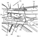
- Fig. 2 illustrates an exploded view of the upper cover 106 and the cowl 114.
- the upper cover 106 and the lower cover 104 act as the exterior covering for a base frame upper 206.
- the exterior mirror assembly 100 may provide at least one aperture 108 for access to a mounting point for various, not shown vehicle accessories such as a spotlight, position light, a camera, a camera monitoring system, at least one sensor such as radar, LIDAR or ultrasonic, a cleaning system for the camera, a windshield, or an aftermarket accessory bracket.
- the at least one aperture 108 may also be integrated into the cowl 114.
- the at least one aperture 108 integrated in the cowl 114 may work independently or in cooperation with the at least one aperture 108 of the mirror assembly 100 to mount a vehicle accessory. It is within the scope of this disclosure to have a cowl mounted mirror assembly with no aperture 108 for exterior mounting of accessories.
- the cowl 114 is a distinct part from the upper cover 106.
- the cowl 114 in Fig. 2 is functionally attached to the upper cover 106.
- the cowl 114 and the upper cover 106 may be combined to be a single integral part and function within the scope of this disclosure.
- a tool (not shown) can be inserted into the or each aperture 108 for dissembling for example the cover part 106 by detaching a clip, snap and/or latch connection.
- the tool can also be used to attach, tighten, release, untighten and the like of any accessory.
- the tool may be in form of a screw driver, a battery drill or the like.
- a base frame upper 206 is provided with at least one mounting connector point 202 which is accessible through the at least one apertures 108, see Fig. 2 .
- the lower cover 104 is attached to base frame upper 206 by the use of known fastener systems such as clips or screws when attaching the lower cover 104 to the base frame upper 206.
- the upper cover 106 attaches to the lower cover 104 with at least one clip 204.
- Known fastener systems in the art could also replace the at least one clip 204 in attaching the upper cover 106 to the lower cover 104.
- the upper cover 106 may also be fastened to the base frame upper 206 to provide additional restraint for the upper cover 106.
- the lower cover 104 and the upper cover 106 may be made of a suitable polymer such as ABS plastic.
- the upper and lower covers 104, 106 cooperate to form a class A surface enclosing the base frame upper 206 when assembled.
- the upper and lower covers 104, 106 and the mirror head 102 may also be coated with a protective layer and/or a decorative layer such as chrome or paint.
- the functional attachment of the cowl 114 to the upper cover 106 in line with Fig. 2 may be a structural connection such as a clip or just an overlap joint between the cowl 114 and the upper cover 106.
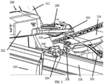
- the cowl 114 engages with a base frame upper first end 208, as best seen in Fig. 3 ) This engagement may be a structural attachment for mounting the cowl 114 such as a clip, or other fastener system known to one skilled in the art.
- the cowl 114 may also include a secondary mounting location to the base frame upper first end (not shown).
- the base frame upper 206 may also provide a support area to the cowl 114 such as a shoulder area to improve stability, reduce vibration, and assist assembly for the cowl 114 when the cowl 114 is assembled.
- the cowl 114 is assembled after the base frame upper 206 is mounted to a base frame lower 304.
- the cowl 114 cooperates with the mirror assembly 100 to form a continuous cover appearance between the upper cover 106 and the cowl 114.
- FIG. 3 illustrates an isometric, exploded view of a mounting of the cowl mounted exterior mirror.
- the base frame lower 304 is provided for mounting the base frame upper 206 and the mirror assembly 100.
- the base frame lower 304 is configured for engage the base frame upper 206.
- the base frame lower 304 may also be configured to mount the cowl 114 and any accessories such as a camera, spotlight or tie down straps.
- the base frame upper 206 connects to an upper end 308 of the base frame lower 304.
- the base frame upper 206 contains a mounting element 310 with a corresponding geometry to the upper end 308 of the base frame lower. In this form, a corresponding geometry of the mounting element 310 couples with a geometry at the upper end 308 of the base frame lower.
- the base frame upper 206 attaches the base frame upper 206 to the base frame lower 304.
- the coupling between the base frame upper 206 and the base frame lower 304 could be a locking configuration between the matching geometries of the base frame lower 304 and the base frame upper 206.
- a wiring harness 302 is routed through the base frame upper 206 to the mirror head 102, as shown in Fig. 3 .
- the wiring harness 302 provides electrical power for the mirror assembly 100.
- the mirror assembly 100 may include modules requiring electrical power such as a camera, a sensor, a power-fold actuator, a telescoping actuator, a mirror adjustment actuator, at least one illumination device 406 shown in Fig. 4 and Fig. 5 , a blind spot indicator, an electrochromic mirror assembly, and/or a heating and/or cooling system for the camera and/or mirror.
- the wiring harness 302 may also include a conduit for supplying a fluid to the mirror assembly 100 for cleaning of a camera or at least one mirror element 602 as indicated in Fig. 6 .
- Fig. 4 and Fig. 5 illustrate one example of the mounting of the base frame lower 304 to the A-pillar 112, and the base frame lower 304 may also be mounted to a hinge pillar 706 in line with Fig. 7 and to a cowl sheet metal 502 in line with Fig. 5 .
- the mounting of the base frame lower 304 to any combination of the A-pillar, hinge pillar, and cowl sheet metal lies within the scope of this disclosure.
- the base frame upper 206 and the base frame lower 304 could also be combined into a single base frame or provide rotational capability between the base frame upper 206 and the base frame lower 304 for mounting the mirror assembly 100.
- the mirror assembly 100 includes the at least one illumination device 406 shown in Fig. 4 and Fig. 5 .
- the at least one illumination device 406 could be an external light module, an internal light module, a front light, a back light, a fog light, a brake light, an acceleration light, a turn signal, a logo lamp, a front area illumination light, a ground illumination light, a puddle light, a flash light, a navigation light, a position light, an emergency light, a spotlight, a green light, a red light, a warning light, a turn signal light module, an approach light, a search light, an information light, a display and/or any combination thereof.
- the at least one illumination device 406 can be a combination of the functions above in a single device or may be multiple illumination devices having their own function.
- the at least one illumination device 406 is shown on the mirror head 102 in Fig. 4 and Fig. 5 .
- the at least one illumination device 406 may be located in any area of the mirror assembly 100 such as incorporated in a bezel 604 shown in Fig. 6 , integrated in the base frame upper 206, the upper cover 106, the lower cover 104 without departing from the scope of this disclosure.
- the at least one illumination device 406 may also be integrated in the mirror head 102 for use behind the at least one mirror element 602 shown in Fig.
- a coating such as a partially transparent chromium or chromium based coating.
- a partially transparent chromium based coating for polymeric substrates such as the mirror head 102 is described in US 2016/0059773, filed on Nov. 9, 2015 for COATED POLYMERIC SUBSTRATES and in US 2017/0015802, filed on Feb. 20, 2015 for DECORATIVE COATINGS FOR PLASTIC SUBSTRATES, which are all hereby incorporated herein by reference.
- the mirror head 102 has a rotational attachment at a pivot joint 404 with the base frame upper 206 and lower cover 104, see Fig. 4 .
- This rotational attachment allows the mirror head 102 to rotate in relation to the vehicle 120 and to the cowl 114 with at least one defined pivot position.
- the rotation of the mirror head 102 about the pivot joint 404 may be achieved manually or with the use of a power-fold actuator (not shown).
- a rear view element folding device for a motor vehicle for approaching at least one pivot position of an element housing relative to an element foot that can be mounted on the motor vehicle, and for locking or unlocking at least one resting position of the element housing relative to the element foot as well as a method for triggering such a rear view element folding device are disclosed in US 2017/0136951A1, filed on November 11, 2016 for REAR VIEW ELEMENT FOLDING DEVICE and EP 3 168 468, filed on November 4, 2016 for RÜCKBLICKELEMENT-KLAPPVORRICHTUNG, both claiming priority to DE 20 2015 106 118.8 filed on November 12, 2015 , which are all hereby incorporated herein by reference.
- Fig. 6 illustrates a top view of the exterior mirror assembly 100.
- the at least one connector point 202 is shown in the base frame upper 206.
- the or rather each connector point 202 can be used for mounting integral original manufacturer supplied accessories or aftermarket accessories to the base frame upper 206.
- the connector point 202 is accessible through the at least one aperture 108 in the upper cover 106 and the cowl 114.
- the at least one mirror element 602 may include a secondary reflective surface known as a spotter mirror (not shown).
- the spotter mirror consists of an integrated spherical convex blind zone mirror inset within a larger planar mirror.
- the at least one mirror element 602 may also be or comprise a camera viewing assembly for capturing and displaying images to a driver.
- the at least one mirror element 602 may also be an electrochromic mirror.
- the electrochromic mirror may be controlled by glare sensors in the mirror or elsewhere on the vehicle.
- the electrochromic mirror may operate in tandem with other electrochromic mirrors in the
- Fig. 7 the mounting of the base frame lower 304 is further illustrated.
- the base frame lower 304 is attached to an A-pillar reinforcement 704.
- the mounted bracket is also fastened to the A-pillar 112, a cowl sheet metal upper 702, a cowl sheet metal lower 708, and the hinge pillar 706.
- the base frame lower 304 is attached to the vehicle independent of the door 110. This allows for the vehicle door 110 to be removed while the mirror assembly 100 remains attached to the vehicle.
Landscapes
- Engineering & Computer Science (AREA)
- Mechanical Engineering (AREA)
- Multimedia (AREA)
- Body Structure For Vehicles (AREA)
- Rear-View Mirror Devices That Are Mounted On The Exterior Of The Vehicle (AREA)
Claims (13)
- Außenrückblickanordnung zur Montage an einem Fahrzeug (120) mit einem Windlauf (114), umfassend:eine Basisbaugruppe, ausgelegt zum Anbringen am Fahrzeug (120), unabhängig davon,ob das Fahrzeug (120) mit einer Fahrzeugtür (110) versehen ist, wobei die Basisbaugruppe zum Anbringen am Windlauf (114) ausgelegt ist; undeine Kopfbaugruppe (102), gekoppelt an die Basisbaugruppe,wobeidie Basisbaugruppe einen Basisrahmen (206, 304) und eine Basisabdeckung (104, 106) umfasst,dadurch gekennzeichnet, dassder Basisrahmen ein Basisrahmenoberteil (206), montierbar an einem Basisrahmenunterteil (304), umfasst,wobeidas Basisrahmenoberteil (206) mit dem Basisrahmenunterteil (304) verbunden ist,indemmindestens ein Montageelement (310) mit einer entsprechenden Geometrie an einem oberen Ende (308) des Basisrahmenunterteils (304) bereitgestellt ist,das Basisrahmenoberteil (206) mit einem ersten Ende (208) zum Anbringen am Windlauf (114) und/oder einem Stützbereich für eine sekundäre Montageposition des Windlaufs (114) versehen ist,
unddas Basisrahmenunterteil (304) zum Montieren des Basisrahmenoberteils (206) undder Kopfbaugruppe (102) vorgesehen ist, und mindestens ein Zubehör und/oder einen Kabelbaum (302). - Außenrückblickanordnung nach Anspruch 1, wobei die Basisabdeckung eine obere Abdeckung (106) und eine untere Abdeckung (104) umfasst.
- Außenrückblickanordnung nach Anspruch 2, wobei
die obere Abdeckung (104) für ein Anbringen am Windlauf (114), insbesondere über mindestens eine Klammer-, Schnapp- und/oder Rastverbindung und/oder eine Überlappungsverbindung, ausgelegt ist. - Außenrückblickanordnung nach einem der vorangehenden Ansprüche, wobei
das Zubehör mindestens eine Beleuchtungsvorrichtung, mindestens eine Kamera, mindestens ein Kameraüberwachungssystem, mindestens einen Sensor, mindestens einen Aktuator, mindestens ein Heizsystem, mindestens ein Kühlsystem, mindestens ein Reinigungssystem für eine Kamera und/oder eine Windschutzscheibe und/oder einen Nachrüstmarkt-Zubehörhalter umfasst. - Außenrückblickanordnung nach einem der vorangehenden Ansprüche, wobeider Kabelbaum (302) mindestens ein elektrisches Kabel umfasst, um einem oder mehreren ersten Modulen, insbesondere umfassend das Zubehör, einen Aktuator für elektrisches Einklappen, einen Teleskopier-Aktuator, einen Spiegeleinstellaktuator, einen elektrochromen Spiegel, elektrische Energie bereitzustellen, und/oderder Kabelbaum (302) mindestens eine Fluidleitung zum Zuführen eines Fluids zu einem oder mehreren zweiten Modulen, insbesondere umfassend das Zubehör, mindestens ein Kühlsystem, mindestens ein Reinigungssystem und/oder mindestens ein Kühlsystem umfasst.
- Außenrückblickanordnung nach einem der vorangehenden Ansprüche, wobei
der Basisrahmen mindestens einen Verbindungspunkt (202) umfasst, der vorzugsweise über mindestens eine Öffnung (108) in der Basisrahmenabdeckung, insbesondere der oberen Abdeckung (106), und/oder dem Windlauf (114) zugänglich ist. - Außenrückblickanordnung nach Anspruch 6, wobeidas Basisrahmenoberteil (206) den oder jeden Verbindungspunkt (202) bereitstellt,
und/oderder oder jeder Verbindungspunkt (202) zum Montieren eines Zubehörs ausgelegt ist. - Außenrückblickanordnung nach einem der vorangehenden Ansprüche, ferner
umfassendein Schwenkgelenk (404) zwischen dem Basisrahmen und der Kopfbaugruppe (102),
und/odermindestens ein Spiegelelement (602), bereitgestellt durch die Kopfbaugruppe. - Fahrzeug (120) mit einem Windlauf (114) und mindestens einer
Außenrückblickanordnung (100) nach einem der vorangehenden Ansprüche. - Fahrzeug nach Anspruch 9, wobeider Windlauf (114) angebaut wird, nachdem das Basisrahmenoberteil (206) an einem Basisrahmenunterteil (304) montiert wurde, und/oderder Windlauf (114) ein von der oberen Abdeckung (106) verschiedenes Teil ist, oder der Windlauf (114) und die obere Abdeckung (106) zu einem einzelnen einstückigen Teil kombiniert sind, und/oderder Windlauf (114) mit der Außenrückblickanordnung (100) zusammenwirkt, um zwischen der oberen Abdeckung (106) und dem Windlauf (114) das Erscheinungsbild einer durchgehenden Abdeckung auszubilden.
- Fahrzeug nach Anspruch 9 oder 10, wobei
das Basisrahmenunterteil (304) an einer A-Säule (112), einer A-Säulen-Verstärkung (704), einem oberen Windlaufmetallblech (702), einem unteren Windlaufmetallblech (708) und/oder einer Scharniersäule (706) angebracht ist. - Fahrzeug nach einem der Ansprüche 9 bis 11, wobei
die obere Abdeckung (106) und/oder der Windlauf (114) zum Montieren des mindestens einen Zubehörs ausgelegt ist/sind, insbesondere durch Bereitstellen mindestens einer Öffnung (108). - Fahrzeug nach einem der Ansprüche 9 bis 12, ferner umfassend mindestens eine Tür (110), eine Haube (116) und/oder ein Seitenteil (118).
Applications Claiming Priority (2)
| Application Number | Priority Date | Filing Date | Title |
|---|---|---|---|
| US202063006750P | 2020-04-08 | 2020-04-08 | |
| PCT/EP2021/058530 WO2021204635A1 (en) | 2020-04-08 | 2021-03-31 | Exterior rear view assembly and vehicle therewith |
Publications (2)
| Publication Number | Publication Date |
|---|---|
| EP4132818A1 EP4132818A1 (de) | 2023-02-15 |
| EP4132818B1 true EP4132818B1 (de) | 2025-05-28 |
Family
ID=75377806
Family Applications (1)
| Application Number | Title | Priority Date | Filing Date |
|---|---|---|---|
| EP21716375.7A Active EP4132818B1 (de) | 2020-04-08 | 2021-03-31 | Aussenrückblickanordnung und fahrzeug damit |
Country Status (3)
| Country | Link |
|---|---|
| US (1) | US12311844B2 (de) |
| EP (1) | EP4132818B1 (de) |
| WO (1) | WO2021204635A1 (de) |
Families Citing this family (7)
| Publication number | Priority date | Publication date | Assignee | Title |
|---|---|---|---|---|
| US12365283B2 (en) | 2019-11-15 | 2025-07-22 | Golight, Inc. | Searchlight system for vehicle post |
| US11938859B2 (en) * | 2019-11-15 | 2024-03-26 | Golight, Inc. | Searchlight system for vehicle post |
| US11752942B2 (en) * | 2020-08-10 | 2023-09-12 | Ford Global Technologies, Llc | Vehicle body structure mounted side view mirror |
| US20220080892A1 (en) * | 2020-09-15 | 2022-03-17 | Ford Global Technologies, Llc | Vehicle body mounted side view mirror assemblies with accessory mounting platforms |
| US20230382302A1 (en) * | 2022-05-26 | 2023-11-30 | Kodiak Robotics, Inc. | Quick swap sensor pod and bracket system |
| US20230382322A1 (en) * | 2022-05-26 | 2023-11-30 | Kodiak Robotics, Inc. | Connecting assembly for a sensor pod |
| USD1117961S1 (en) | 2024-08-15 | 2026-03-10 | Golight, Inc. | Mounting bracket for a vehicle-mountable searchlight system |
Family Cites Families (9)
| Publication number | Priority date | Publication date | Assignee | Title |
|---|---|---|---|---|
| US2447786A (en) * | 1946-01-26 | 1948-08-24 | Monarch Governor Company | Rearview mirror |
| EP1437261B1 (de) * | 2002-12-20 | 2007-09-12 | Murakami Corporation | Aussenspiegel |
| JP6251189B2 (ja) | 2012-01-24 | 2017-12-20 | エスエムアール・パテンツ・ソシエテ・ア・レスポンサビリテ・リミテ | クロムをベースとする反射被膜 |
| JP5941810B2 (ja) * | 2012-09-28 | 2016-06-29 | 本田技研工業株式会社 | 鞍乗型車両のフロントカウル構造 |
| US20140239143A1 (en) * | 2013-02-22 | 2014-08-28 | Jose D. Hernandez | Mounting Bracket for a Mirror |
| WO2015131223A1 (en) | 2014-03-07 | 2015-09-11 | University Of South Australia | Decorative coatings for plastic substrates |
| DE202015106118U1 (de) | 2015-11-12 | 2015-11-30 | SMR Patents S.à.r.l. | Rückblickelement-Klappvorrichtung |
| US11192504B2 (en) * | 2018-03-09 | 2021-12-07 | Omix-Ada, Inc. | Hinge mount system for utility vehicle |
| US20190283674A1 (en) * | 2018-03-16 | 2019-09-19 | Omix-Ada | Quick release mirror mount |
-
2021
- 2021-03-31 EP EP21716375.7A patent/EP4132818B1/de active Active
- 2021-03-31 US US17/917,317 patent/US12311844B2/en active Active
- 2021-03-31 WO PCT/EP2021/058530 patent/WO2021204635A1/en not_active Ceased
Also Published As
| Publication number | Publication date |
|---|---|
| EP4132818A1 (de) | 2023-02-15 |
| US20230144329A1 (en) | 2023-05-11 |
| US12311844B2 (en) | 2025-05-27 |
| WO2021204635A1 (en) | 2021-10-14 |
Similar Documents
| Publication | Publication Date | Title |
|---|---|---|
| EP4132818B1 (de) | Aussenrückblickanordnung und fahrzeug damit | |
| US10543786B2 (en) | Vehicle camera system | |
| EP0873910B1 (de) | Aussenrückspiegelkomponenten und deren Zusammenbauverfahren | |
| US10099618B2 (en) | Exterior rearview mirror assembly | |
| US8378802B2 (en) | Exterior rear view mirror with indicator light | |
| US11325535B2 (en) | Exterior rearview mirror assembly | |
| US20030122929A1 (en) | Vehicular camera system | |
| US20220080892A1 (en) | Vehicle body mounted side view mirror assemblies with accessory mounting platforms | |
| US4832476A (en) | Blind spot viewing mirror system | |
| US10594989B2 (en) | Safety mirror with telescoping head and motor vehicle | |
| CN110303984B (zh) | 车身后部构造 | |
| CA2354715A1 (en) | Extendable mirror | |
| US11872940B2 (en) | Vehicle body mounted side view mirror assemblies with off-roading and vehicle security features | |
| US11180088B2 (en) | Mounting assembly for an exterior attachment device, rearview device and motor vehicle | |
| US20230111473A1 (en) | Support for a camera display of a vehicle | |
| WO2001028814A2 (en) | Interchangeable mirror scalp for trailer towing | |
| US7963590B2 (en) | Assembly for vehicles including adjustable mirrors | |
| US20240092265A1 (en) | Vehicular side door with integrated base for exterior mirror | |
| US20220258669A1 (en) | Vehicular exterior rearview mirror assembly | |
| US20050052762A1 (en) | Method and apparatus for safely backing a vehicle into a traffic lane | |
| US20110249465A1 (en) | Directional safety mirror "flasher" | |
| KR200190421Y1 (ko) | 자동차용 사이드회전미러 | |
| CN118636830A (zh) | 一种车载外后视镜镜片防盗装置、后视镜及防盗方法 | |
| KR200190377Y1 (ko) | 오토 백 미러 | |
| KR20010081590A (ko) | 오토 백 미러 |
Legal Events
| Date | Code | Title | Description |
|---|---|---|---|
| STAA | Information on the status of an ep patent application or granted ep patent |
Free format text: STATUS: UNKNOWN |
|
| STAA | Information on the status of an ep patent application or granted ep patent |
Free format text: STATUS: THE INTERNATIONAL PUBLICATION HAS BEEN MADE |
|
| PUAI | Public reference made under article 153(3) epc to a published international application that has entered the european phase |
Free format text: ORIGINAL CODE: 0009012 |
|
| STAA | Information on the status of an ep patent application or granted ep patent |
Free format text: STATUS: REQUEST FOR EXAMINATION WAS MADE |
|
| 17P | Request for examination filed |
Effective date: 20221104 |
|
| AK | Designated contracting states |
Kind code of ref document: A1 Designated state(s): AL AT BE BG CH CY CZ DE DK EE ES FI FR GB GR HR HU IE IS IT LI LT LU LV MC MK MT NL NO PL PT RO RS SE SI SK SM TR |
|
| DAV | Request for validation of the european patent (deleted) | ||
| DAX | Request for extension of the european patent (deleted) | ||
| P01 | Opt-out of the competence of the unified patent court (upc) registered |
Effective date: 20230616 |
|
| STAA | Information on the status of an ep patent application or granted ep patent |
Free format text: STATUS: EXAMINATION IS IN PROGRESS |
|
| 17Q | First examination report despatched |
Effective date: 20240109 |
|
| GRAP | Despatch of communication of intention to grant a patent |
Free format text: ORIGINAL CODE: EPIDOSNIGR1 |
|
| STAA | Information on the status of an ep patent application or granted ep patent |
Free format text: STATUS: GRANT OF PATENT IS INTENDED |
|
| INTG | Intention to grant announced |
Effective date: 20250113 |
|
| GRAS | Grant fee paid |
Free format text: ORIGINAL CODE: EPIDOSNIGR3 |
|
| GRAA | (expected) grant |
Free format text: ORIGINAL CODE: 0009210 |
|
| STAA | Information on the status of an ep patent application or granted ep patent |
Free format text: STATUS: THE PATENT HAS BEEN GRANTED |
|
| AK | Designated contracting states |
Kind code of ref document: B1 Designated state(s): AL AT BE BG CH CY CZ DE DK EE ES FI FR GB GR HR HU IE IS IT LI LT LU LV MC MK MT NL NO PL PT RO RS SE SI SK SM TR |
|
| REG | Reference to a national code |
Ref country code: GB Ref legal event code: FG4D |
|
| REG | Reference to a national code |
Ref country code: CH Ref legal event code: EP |
|
| REG | Reference to a national code |
Ref country code: DE Ref legal event code: R096 Ref document number: 602021031414 Country of ref document: DE |
|
| REG | Reference to a national code |
Ref country code: IE Ref legal event code: FG4D |
|
| REG | Reference to a national code |
Ref country code: NL Ref legal event code: MP Effective date: 20250528 |
|
| PG25 | Lapsed in a contracting state [announced via postgrant information from national office to epo] |
Ref country code: ES Free format text: LAPSE BECAUSE OF FAILURE TO SUBMIT A TRANSLATION OF THE DESCRIPTION OR TO PAY THE FEE WITHIN THE PRESCRIBED TIME-LIMIT Effective date: 20250528 Ref country code: FI Free format text: LAPSE BECAUSE OF FAILURE TO SUBMIT A TRANSLATION OF THE DESCRIPTION OR TO PAY THE FEE WITHIN THE PRESCRIBED TIME-LIMIT Effective date: 20250528 |
|
| REG | Reference to a national code |
Ref country code: LT Ref legal event code: MG9D |
|
| PG25 | Lapsed in a contracting state [announced via postgrant information from national office to epo] |
Ref country code: NO Free format text: LAPSE BECAUSE OF FAILURE TO SUBMIT A TRANSLATION OF THE DESCRIPTION OR TO PAY THE FEE WITHIN THE PRESCRIBED TIME-LIMIT Effective date: 20250828 Ref country code: GR Free format text: LAPSE BECAUSE OF FAILURE TO SUBMIT A TRANSLATION OF THE DESCRIPTION OR TO PAY THE FEE WITHIN THE PRESCRIBED TIME-LIMIT Effective date: 20250829 |
|
| PG25 | Lapsed in a contracting state [announced via postgrant information from national office to epo] |
Ref country code: NL Free format text: LAPSE BECAUSE OF FAILURE TO SUBMIT A TRANSLATION OF THE DESCRIPTION OR TO PAY THE FEE WITHIN THE PRESCRIBED TIME-LIMIT Effective date: 20250528 Ref country code: PL Free format text: LAPSE BECAUSE OF FAILURE TO SUBMIT A TRANSLATION OF THE DESCRIPTION OR TO PAY THE FEE WITHIN THE PRESCRIBED TIME-LIMIT Effective date: 20250528 |
|
| PG25 | Lapsed in a contracting state [announced via postgrant information from national office to epo] |
Ref country code: BG Free format text: LAPSE BECAUSE OF FAILURE TO SUBMIT A TRANSLATION OF THE DESCRIPTION OR TO PAY THE FEE WITHIN THE PRESCRIBED TIME-LIMIT Effective date: 20250528 |
|
| PG25 | Lapsed in a contracting state [announced via postgrant information from national office to epo] |
Ref country code: HR Free format text: LAPSE BECAUSE OF FAILURE TO SUBMIT A TRANSLATION OF THE DESCRIPTION OR TO PAY THE FEE WITHIN THE PRESCRIBED TIME-LIMIT Effective date: 20250528 |
|
| PG25 | Lapsed in a contracting state [announced via postgrant information from national office to epo] |
Ref country code: RS Free format text: LAPSE BECAUSE OF FAILURE TO SUBMIT A TRANSLATION OF THE DESCRIPTION OR TO PAY THE FEE WITHIN THE PRESCRIBED TIME-LIMIT Effective date: 20250828 |
|
| PG25 | Lapsed in a contracting state [announced via postgrant information from national office to epo] |
Ref country code: IS Free format text: LAPSE BECAUSE OF FAILURE TO SUBMIT A TRANSLATION OF THE DESCRIPTION OR TO PAY THE FEE WITHIN THE PRESCRIBED TIME-LIMIT Effective date: 20250928 |
|
| PG25 | Lapsed in a contracting state [announced via postgrant information from national office to epo] |
Ref country code: LV Free format text: LAPSE BECAUSE OF FAILURE TO SUBMIT A TRANSLATION OF THE DESCRIPTION OR TO PAY THE FEE WITHIN THE PRESCRIBED TIME-LIMIT Effective date: 20250528 |
|
| REG | Reference to a national code |
Ref country code: AT Ref legal event code: MK05 Ref document number: 1798465 Country of ref document: AT Kind code of ref document: T Effective date: 20250528 |
|
| PG25 | Lapsed in a contracting state [announced via postgrant information from national office to epo] |
Ref country code: DK Free format text: LAPSE BECAUSE OF FAILURE TO SUBMIT A TRANSLATION OF THE DESCRIPTION OR TO PAY THE FEE WITHIN THE PRESCRIBED TIME-LIMIT Effective date: 20250528 Ref country code: AT Free format text: LAPSE BECAUSE OF FAILURE TO SUBMIT A TRANSLATION OF THE DESCRIPTION OR TO PAY THE FEE WITHIN THE PRESCRIBED TIME-LIMIT Effective date: 20250528 Ref country code: SM Free format text: LAPSE BECAUSE OF FAILURE TO SUBMIT A TRANSLATION OF THE DESCRIPTION OR TO PAY THE FEE WITHIN THE PRESCRIBED TIME-LIMIT Effective date: 20250528 |
|
| PG25 | Lapsed in a contracting state [announced via postgrant information from national office to epo] |
Ref country code: CZ Free format text: LAPSE BECAUSE OF FAILURE TO SUBMIT A TRANSLATION OF THE DESCRIPTION OR TO PAY THE FEE WITHIN THE PRESCRIBED TIME-LIMIT Effective date: 20250528 |
|
| PG25 | Lapsed in a contracting state [announced via postgrant information from national office to epo] |
Ref country code: EE Free format text: LAPSE BECAUSE OF FAILURE TO SUBMIT A TRANSLATION OF THE DESCRIPTION OR TO PAY THE FEE WITHIN THE PRESCRIBED TIME-LIMIT Effective date: 20250528 |
|
| PG25 | Lapsed in a contracting state [announced via postgrant information from national office to epo] |
Ref country code: SK Free format text: LAPSE BECAUSE OF FAILURE TO SUBMIT A TRANSLATION OF THE DESCRIPTION OR TO PAY THE FEE WITHIN THE PRESCRIBED TIME-LIMIT Effective date: 20250528 |
|
| PG25 | Lapsed in a contracting state [announced via postgrant information from national office to epo] |
Ref country code: IT Free format text: LAPSE BECAUSE OF FAILURE TO SUBMIT A TRANSLATION OF THE DESCRIPTION OR TO PAY THE FEE WITHIN THE PRESCRIBED TIME-LIMIT Effective date: 20250528 |
|
| REG | Reference to a national code |
Ref country code: CH Ref legal event code: W10 Free format text: ST27 STATUS EVENT CODE: U-0-0-W10-W00 (AS PROVIDED BY THE NATIONAL OFFICE) Effective date: 20260225 |
|
| REG | Reference to a national code |
Ref country code: DE Ref legal event code: R097 Ref document number: 602021031414 Country of ref document: DE |
|
| RAP4 | Party data changed (patent owner data changed or rights of a patent transferred) |
Owner name: MOTHERSON INNOVATIONS COMPANY LIMITED |
|
| PLBE | No opposition filed within time limit |
Free format text: ORIGINAL CODE: 0009261 |
|
| STAA | Information on the status of an ep patent application or granted ep patent |
Free format text: STATUS: NO OPPOSITION FILED WITHIN TIME LIMIT |
|
| PGFP | Annual fee paid to national office [announced via postgrant information from national office to epo] |
Ref country code: GB Payment date: 20260317 Year of fee payment: 6 |
|
| REG | Reference to a national code |
Ref country code: CH Ref legal event code: L10 Free format text: ST27 STATUS EVENT CODE: U-0-0-L10-L00 (AS PROVIDED BY THE NATIONAL OFFICE) Effective date: 20260409 |
|
| PGFP | Annual fee paid to national office [announced via postgrant information from national office to epo] |
Ref country code: DE Payment date: 20260320 Year of fee payment: 6 |
|
| PGFP | Annual fee paid to national office [announced via postgrant information from national office to epo] |
Ref country code: FR Payment date: 20260324 Year of fee payment: 6 |