EP4132726B1 - Spraying booth - Google Patents
Spraying booth Download PDFInfo
- Publication number
- EP4132726B1 EP4132726B1 EP21722283.5A EP21722283A EP4132726B1 EP 4132726 B1 EP4132726 B1 EP 4132726B1 EP 21722283 A EP21722283 A EP 21722283A EP 4132726 B1 EP4132726 B1 EP 4132726B1
- Authority
- EP
- European Patent Office
- Prior art keywords
- booth
- movement
- spraying
- compartment
- stretch
- Prior art date
- Legal status (The legal status is an assumption and is not a legal conclusion. Google has not performed a legal analysis and makes no representation as to the accuracy of the status listed.)
- Active
Links
Images


Classifications
-
- B—PERFORMING OPERATIONS; TRANSPORTING
- B05—SPRAYING OR ATOMISING IN GENERAL; APPLYING FLUENT MATERIALS TO SURFACES, IN GENERAL
- B05B—SPRAYING APPARATUS; ATOMISING APPARATUS; NOZZLES
- B05B14/00—Arrangements for collecting, re-using or eliminating excess spraying material
- B05B14/40—Arrangements for collecting, re-using or eliminating excess spraying material for use in spray booths
- B05B14/48—Arrangements for collecting, re-using or eliminating excess spraying material for use in spray booths specially adapted for particulate material
-
- B—PERFORMING OPERATIONS; TRANSPORTING
- B05—SPRAYING OR ATOMISING IN GENERAL; APPLYING FLUENT MATERIALS TO SURFACES, IN GENERAL
- B05B—SPRAYING APPARATUS; ATOMISING APPARATUS; NOZZLES
- B05B13/00—Machines or plants for applying liquids or other fluent materials to surfaces of objects or other work by spraying, not covered by groups B05B1/00 - B05B11/00
- B05B13/02—Means for supporting work; Arrangement or mounting of spray heads; Adaptation or arrangement of means for feeding work
- B05B13/04—Means for supporting work; Arrangement or mounting of spray heads; Adaptation or arrangement of means for feeding work the spray heads being moved during spraying operation
- B05B13/0405—Means for supporting work; Arrangement or mounting of spray heads; Adaptation or arrangement of means for feeding work the spray heads being moved during spraying operation with reciprocating or oscillating spray heads
- B05B13/041—Means for supporting work; Arrangement or mounting of spray heads; Adaptation or arrangement of means for feeding work the spray heads being moved during spraying operation with reciprocating or oscillating spray heads with spray heads reciprocating along a straight line
- B05B13/0415—Means for supporting work; Arrangement or mounting of spray heads; Adaptation or arrangement of means for feeding work the spray heads being moved during spraying operation with reciprocating or oscillating spray heads with spray heads reciprocating along a straight line the angular position of the spray heads relative to the straight line being modified during the reciprocating movement
-
- B—PERFORMING OPERATIONS; TRANSPORTING
- B05—SPRAYING OR ATOMISING IN GENERAL; APPLYING FLUENT MATERIALS TO SURFACES, IN GENERAL
- B05B—SPRAYING APPARATUS; ATOMISING APPARATUS; NOZZLES
- B05B15/00—Details of spraying plant or spraying apparatus not otherwise provided for; Accessories
- B05B15/50—Arrangements for cleaning; Arrangements for preventing deposits, drying-out or blockage; Arrangements for detecting improper discharge caused by the presence of foreign matter
- B05B15/52—Arrangements for cleaning; Arrangements for preventing deposits, drying-out or blockage; Arrangements for detecting improper discharge caused by the presence of foreign matter for removal of clogging particles
-
- B—PERFORMING OPERATIONS; TRANSPORTING
- B05—SPRAYING OR ATOMISING IN GENERAL; APPLYING FLUENT MATERIALS TO SURFACES, IN GENERAL
- B05B—SPRAYING APPARATUS; ATOMISING APPARATUS; NOZZLES
- B05B15/00—Details of spraying plant or spraying apparatus not otherwise provided for; Accessories
- B05B15/50—Arrangements for cleaning; Arrangements for preventing deposits, drying-out or blockage; Arrangements for detecting improper discharge caused by the presence of foreign matter
- B05B15/55—Arrangements for cleaning; Arrangements for preventing deposits, drying-out or blockage; Arrangements for detecting improper discharge caused by the presence of foreign matter using cleaning fluids
- B05B15/555—Arrangements for cleaning; Arrangements for preventing deposits, drying-out or blockage; Arrangements for detecting improper discharge caused by the presence of foreign matter using cleaning fluids discharged by cleaning nozzles
-
- B—PERFORMING OPERATIONS; TRANSPORTING
- B05—SPRAYING OR ATOMISING IN GENERAL; APPLYING FLUENT MATERIALS TO SURFACES, IN GENERAL
- B05B—SPRAYING APPARATUS; ATOMISING APPARATUS; NOZZLES
- B05B15/00—Details of spraying plant or spraying apparatus not otherwise provided for; Accessories
- B05B15/70—Arrangements for moving spray heads automatically to or from the working position
-
- B—PERFORMING OPERATIONS; TRANSPORTING
- B08—CLEANING
- B08B—CLEANING IN GENERAL; PREVENTION OF FOULING IN GENERAL
- B08B3/00—Cleaning by methods involving the use or presence of liquid or steam
- B08B3/02—Cleaning by the force of jets or sprays
- B08B3/024—Cleaning by means of spray elements moving over the surface to be cleaned
-
- B—PERFORMING OPERATIONS; TRANSPORTING
- B08—CLEANING
- B08B—CLEANING IN GENERAL; PREVENTION OF FOULING IN GENERAL
- B08B9/00—Cleaning hollow articles by methods or apparatus specially adapted thereto
-
- Y—GENERAL TAGGING OF NEW TECHNOLOGICAL DEVELOPMENTS; GENERAL TAGGING OF CROSS-SECTIONAL TECHNOLOGIES SPANNING OVER SEVERAL SECTIONS OF THE IPC; TECHNICAL SUBJECTS COVERED BY FORMER USPC CROSS-REFERENCE ART COLLECTIONS [XRACs] AND DIGESTS
- Y02—TECHNOLOGIES OR APPLICATIONS FOR MITIGATION OR ADAPTATION AGAINST CLIMATE CHANGE
- Y02P—CLIMATE CHANGE MITIGATION TECHNOLOGIES IN THE PRODUCTION OR PROCESSING OF GOODS
- Y02P70/00—Climate change mitigation technologies in the production process for final industrial or consumer products
- Y02P70/10—Greenhouse gas [GHG] capture, material saving, heat recovery or other energy efficient measures, e.g. motor control, characterised by manufacturing processes, e.g. for rolling metal or metal working
Definitions
- the present invention relates to a spraying booth, particularly for powder coating.
- booths are designed for the coating of different types of products and manufactured articles, such as, e.g., car components, fixtures, furnishing elements, etc. see for example US2007/062444 .
- Coating is a process of surface covering carried out both for decorative purposes, by coloring the elements to be coated, and for purposes of protection against corrosion, external agents, etc.
- the coating is created by spraying powders of organic matrix and synthetic resins which, by adhering to the surfaces, color the element being coated.
- the element is placed in special kilns where, through a heat treatment, the powders and resins melt and polymerize, thus forming the final coating layer.
- known type of booths define the space in which the coating takes place and are provided with walls that define the volume thereof.
- the roof and the floor there are two front walls, which can be opened to allow access to the operators in charge, and two side walls provided with slits adapted to house the coating devices, such as spray guns, nozzles, and the like.
- These devices are usually electronically controlled and have the function of sprinkling powder on the elements inserted in the booth.
- the powder that does not adhere to the elements falls on the booth's floor and is sucked up by a suction system which is adapted to recover the fallen powder for later reuse.
- the same booth is intended to accommodate successive coatings with powders that are different from those previously used, for example, in order to obtain products of a different color.
- the different phases of work involve changes of color that, in addition to the replacement of the powders to be used, involve the complete cleaning of the interior of the booth.
- a drawback of known type of booths is, therefore, precisely related to the cleaning operations, which are necessary before each color change.
- upgraded spraying booths inside which automated cleaning means are installed, provided with an anthropomorphic boom provided with appropriate cleaning devices adapted to carry out the cleaning operations.
- Spraying booths are also known provided with a mobile, vertically sliding roof, which are provided with suitable cleaning means supported by the roof itself, facing the inside of the booth and adapted to carry out the cleaning operations during the descent and/or rise of the roof.
- the main aim of the present invention is to devise a spraying booth, the interior of which can be systematically cleaned in a rational and automated manner, but with a reduction in its technical and structural complexity compared to booths of known type.
- reference numeral 1 globally indicates a spraying booth.
- the booth 1 comprises:
- the cleaning means 29 are not shown in Figures 1-6 , but are shown in detail in Figures 7-10 .
- the supporting frame 6, 7 is arranged to rest on a stable resting surface 3, i.e., a substantially horizontal flat surface, such as e.g. the ground, as shown in Figure 1 .
- the supporting frame 6, 7 comprises at least one resting element 6 on the stable resting surface 3 of the type of an elongated body extending, in use, vertically.
- the supporting frame 6, 7 comprises a plurality of resting elements 6 and each defining a corresponding fixed resting point on the stable resting surface 3.
- the supporting frame 6, 7 comprises at least one cross member 7, which extends at least partly above the spraying compartment 4 and facing at least partly the access opening 5.
- the cleaning means 29 are mounted on the cross member 7 above the spraying compartment 4 and facing the access opening 5.
- the movement means 40 make the cleaning means 29 vertically movable between the home configuration and the operating configuration.
- the spraying compartment 4 comprises a bedplate 31 opposite the access opening 5.
- the spraying compartment 4 comprises a side wall 10, which extends from the bedplate 31 to end up at the point where the access opening 5 is located. This way, the side wall 10 and the bedplate 31 define a spraying compartment 4 of substantially hollow shape.
- the spraying compartment 4 comprises one or more slits 32, cut through the side wall 10 and adapted to allow the insertion of suitable spraying means 33 into the compartment 4.
- the spraying compartment 4 comprises at least one access port 2 formed on the side wall 10 adapted, e.g., to allow the insertion/removal into/out of the spraying compartment 4 of at least one product to be coated.
- the booth 1 comprises closing/opening means, not shown in the figures, of the access port 2.
- the closing/opening means comprise at least one clamping body coupled in a movable manner to the spraying compartment 4 close to the access port 2, by sealing it, in the operating configuration, and away from the access port 2, by releasing it, in the home configuration.
- the movement means 40 comprise at least one holding boom 8 of the cleaning means 29, mounted movable along a direction of movement A on the supporting frame 6, 7, arranged at least partly inside the spraying compartment 4, if in the operating configuration, and completely outside the spraying compartment 4, if in the home configuration.
- the movement means 40 comprise guidance means 15, 16, 17 of the holding boom 8 along the direction of movement A, inside and outside of the spraying booth 1.
- the movement means 40 comprise actuator means 18, 19, 20, 35, 36, 37, which are adapted to move the holding boom 8 along the direction of movement A.
- the holding boom 8 extends vertically along the direction of movement A.
- the holding boom 8 has a substantially elongated shape along the direction of movement A, so as to reduce the clearance of the same inside the spraying compartment 4.
- the holding boom 8 is mounted on the cross member 7, which extends substantially horizontally above the access opening 5, as shown in Figures 3 and 4 .
- the holding boom 8 is a telescopic boom, extending inside the compartment 4 along the direction of movement A, in an operating configuration, and retracted outside the compartment 4 along the direction of movement A, in the home configuration.
- the holding boom 8 comprises:
- the second stretch 13 is mounted on the first stretch 12 and is made integral by shifting with the latter and following the movement thereof along a predefined first stroke of the first stretch 12 with respect to the supporting frame 6, 7.
- the second stretch 13 is movable with respect to the first stretch 12 along a second predefined stroke.
- the total extension of the holding boom 8 is defined by the sum of the first stroke and of the second stroke.
- the guidance means 15, 16, 17 comprise a first rectilinear guide 15, positioned between the supporting frame 6, 7 and the first stretch 12, and the actuator means 18, 19, 20, 35, 36, 37 comprise a first actuator assembly 18, 35, mounted on at least one of either the supporting frame 6, 7 or the first stretch 12 to move the latter along the first rectilinear guide 15.
- the guidance means 15, 16, 17 comprise a second rectilinear guide 16, positioned between the first stretch and the second stretch 12, 13, and the actuator means 18, 19, 20, 35, 36, 37 comprise a second actuator assembly 19, 36 mounted on at least one of either the first stretch or the second stretch 12, 13, to move the latter along the second rectilinear guide 16.
- first stretch and the second stretch 12, 13 are placed substantially juxtaposed and parallel to each other, in the home configuration, and substantially aligned longitudinally with each other along the direction of movement A, in the operating configuration.
- the holding boom 8 comprises at least one intermediate stretch 14, which is positioned between the first stretch and the second stretch 12, 13 and is coupled movable in a sliding manner along the direction of movement A.
- the intermediate stretch 14 is arranged juxtaposed and substantially parallel to the two stretches 12, 13, in the home configuration, and substantially aligned longitudinally to the two stretches 12, 13 along the direction of movement A, in the operating configuration.
- the intermediate stretch 14 keeps the clearance of the holding boom 8 small, i.e., it does not increase its vertical overhead clearance above the booth 1.
- the guidance means 15, 16, 17 comprise an intermediate rectilinear guide 17, positioned between the intermediate stretch 14 and one of either the first stretch 12 or the second stretch 13.
- the second rectilinear guide 16 is positioned between the intermediate stretch 14 and the other of either the first stretch 12 or the second stretch 13.
- the actuator means 18, 19, 20, 35, 36, 37 comprise an intermediate actuator assembly 20, 37 mounted on at least one of either the intermediate stretch 14, the first stretch 12, or the second stretch 13.
- the holding boom 8 comprises a plurality of intermediate stretches 14 coupled movable and sliding along the direction of movement A to each other, by interposition of respective intermediate rectilinear guides 17, and movable along the same by means of respective intermediate actuator assemblies 20, 37.
- the first stretch and the second stretch 12, 13 have a substantially equal length to the intermediate stretch 14.
- Embodiments of the booth cannot however be ruled out wherein at least one of either the first, the second or the intermediate stretches 12, 13, 14 is longer than at least one of the other stretches 12, 13, 14.
- the stretches 12, 13, 14 have a substantially elongated shape, so as to minimize their clearance inside the spraying compartment 4.
- the first actuator assembly 18, 35 comprises a first actuator 18, mounted on the supporting frame 6, and a first rack 35, associated with the first stretch 12 along the direction of movement A and mechanically coupled to the first actuator 18.
- the intermediate actuator assembly 20, 37 comprises an intermediate actuator 20, mounted on the second stretch 13, and an intermediate rack 37, associated with the intermediate stretch 14 along the direction of movement A and mechanically coupled to the intermediate actuator 20.
- the second actuator assembly 19, 36 comprises a second actuator 19, coinciding with the intermediate actuator 20, and a second rack 36, associated with the first stretch 12 along the direction of movement A and mechanically coupleable to the intermediate actuator 20.
- the intermediate actuator 20 comprises a first gear wheel 38, mechanically coupleable to the second rack 36, and a second gear wheel 39, mechanically coupleable to the intermediate rack 37, as shown in Figures 5 and 6 .
- the intermediate actuator 20 engages the intermediate rack 37 and moves the second stretch 13 facing the intermediate stretch 14, until it allows the second gear wheel 39 to engage the second rack 36 and move the second stretch 13 facing the first stretch 12.
- the movement means 40 comprise securing means, not shown in the figures, of the second stretch 13 to the intermediate stretch 14.
- the securing means are configured to secure the intermediate stretch 14 to the second stretch 13 during the movement of the holding boom 8 from the operating configuration to the home configuration, i.e., during the ascent of the second stretch 13, to also move the intermediate stretch 14 facing the first stretch 12.
- the movement means 40 comprise a plurality of holding booms 8.
- the movement means 40 comprise guidance means 15, 16, 17 and actuator means 18, 19, 20, 35, 36, 37 in the same number as the holding booms 8.
- the holding booms 8 are arranged at the same height and at predefined positions corresponding to the vertices of a square.
- the supporting frame 6, 7 comprises a pair of cross members 7 extending vertically parallel to each other above the access opening 5, on each cross member 7 being mounted a pair of holding booms 8, as shown in Figure 2 .
- the cleaning means 29 comprise at least one cleaning device 21, 23 of the spraying compartment 4, selected from the list comprising a pneumatic dispensing device 21, a hydraulic dispensing device and an absorbing element 23.
- the pneumatic dispensing device 21 is of the type of a dispenser provided with at least one nozzle through which a pressurized air stream is delivered.
- the hydraulic dispensing device is preferably of the type of a dispenser provided with at least one nozzle through which at least one liquid cleaning solution is delivered.
- the characteristics relating to the pneumatic dispensing device 21 are to be considered valid also for the hydraulic dispensing device, since the only difference between these devices lies in the nature of the fluid delivered.
- the absorbing element 23 is of the type of a sponge, a cloth, or the like.
- the absorbing element 23 is a sponge.
- the pneumatic dispensing device 21 is angled downwards, so as to direct the air stream abutting against the vertical walls of the compartment 4 towards the bedplate 31 and not towards the access opening 5.
- the spraying booth 1 comprises suction means 24, that are arranged at the point where the bedplate 31 of the booth itself is located and that are adapted to extract the fluids present inside the spraying compartment 4.
- the suction means 24 coincide with the suction means used for the suction of the paint during the coating steps.
- the cleaning means 29 comprise a plurality of hydraulic dispensing devices, a plurality of pneumatic dispensing devices, and a plurality of absorbing elements 23, each arranged to operate on a predefined portion of the spraying compartment 4, to intervene substantially on the entire perimeter of the compartment itself.
- the cleaning devices 21, 23 vertically explore the perimeter of the spraying compartment 4, by cleaning the entire surface extension of the interior surface 11.
- the pneumatic dispensing device 21 is arranged at a lower height than the absorbing element 23.
- the absorbing element 23 slides in contact with the interior surfaces of the spraying compartment 4 to follow the pneumatic dispensing device 21.
- the movement means 40 comprise at least one holding frame 25a, 25b, associated with the holding boom 8.
- At least one cleaning device 21, 23 is mounted on the holding frame 25a, 25b and, in an operating configuration, is placed facing and/or in contact with the spraying compartment 4, thus cleaning it.
- the holding frame 25a, 25b is associated with the second stretch 13.
- the holding frame 25a, 25b is associated with a plurality of second stretches 13.
- the holding frame 25a, 25b comprises a first supporting element 25a, associated with a pair of second stretches 13, and a second supporting element 25b, associated with another pair of second stretches 13, to substantially define a holding frame 25a, 25b, facing the spraying compartment 4 along its entire perimeter.
- the holding frame 25a, 25b is associated with each second stretch 13 of each holding boom 8 and comprises four connecting elements, which are positioned between corresponding pairs of holding booms 8 respectively, to make a substantially continuous holding frame 25a, 25b of substantially square shape.
- the cleaning devices 21, 23 are mounted on the supporting elements 25a, 25b, so as to operate on the entire perimeter of the interior surface 11.
- the holding frame 25a, 25b defines at least one vacuous portion 41, which allows the passage of external elements, arranged inside the spraying compartment 4, such as e.g. paint dispensers or the like.
- the holding frame 25a, 25b defines at least one vacuous portion 41, at the point where the first supporting element 25a is located, and at least one vacuous portion 41, at the point where the second supporting element 25b is located, as shown in Figure 8 .
- the holding frame 25a, 25b defines a plurality of vacuous portions 41, such as e.g. a pair of vacuous portions 41 at the point where each supporting element 25a, 25b is located.
- the booth 1 comprises operating means 42 of the cleaning means 29 configured to activate/deactivate at least one of the cleaning devices 21, 23.
- the operating means 42 comprise at least one operating assembly, not shown in the figures, positioned between the holding frame 25a, 25b and the absorbing element 23 and configured to move the absorbing element 23 close to the side wall 10, in order to abut against the interior surface 11, and away from the side wall 10.
- the operating assembly moves the absorbing element 23 to abut against the interior surface 11.
- This solution allows the absorbing element 23 to slide in contact with the interior surface 11, thus absorbing any liquids and/or paint residue present thereon.
- the booth 1 comprises displacement means 44, 45 of at least one of the cleaning device 21, 23 between at least a first configuration of use, wherein the cleaning device 21, 23 faces the side wall 10, and at least a second configuration of use, wherein the cleaning device faces the bedplate 31.
- the displacement means 44, 45 comprise at least one rotation assembly 45 of the cleaning device 21, 23 around an axis of rotation E to move the latter between the first and the second configuration of use.
- the displacement means 44, 45 also comprise at least one longitudinal movement assembly 44 of the cleaning device 21, 23 along a direction of displacement D arranged parallel with respect to the bedplate 31.
- the axis of rotation E is transverse with respect to the direction of displacement D.
- the axis of rotation E is orthogonal with respect to the direction of displacement D.
- the rotation assembly 45 is positioned between at least one cleaning device 21, 23 and the longitudinal movement means 44, and the longitudinal movement assembly 44 is positioned between the longitudinal movement means 44 and the rotation assembly 45.
- the longitudinal movement assembly 44 is positioned between at least one holding boom 8 and the rotation assembly 45.
- displacement means 44, 45 cannot be ruled out, wherein the longitudinal movement assembly 44 is positioned between the holding frame 25a, 25b and the rotation assembly 45.
- the longitudinal movement assembly 44 moves the cleaning device 21, 23 along the direction of displacement D, thus cleaning the bedplate 31.
- the longitudinal movement assembly 44 comprises at least one guidance assembly 43 which extends longitudinally along the direction of displacement D and the rotation assembly 45 is coupled in a sliding manner along the guidance assembly 43.
- the cleaning device 21, 23 is a pneumatic dispensing device 21.
- the displacement means 44, 45 are configured to move a plurality of pneumatic dispensing devices 21 arranged aligned with each other along a direction of arrangement substantially parallel to the axis of rotation E.
- pneumatic dispensing device 21 cannot be ruled out, wherein the same comprises a plurality of dispensers arranged aligned with each other along a direction of positioning substantially parallel to the axis of rotation E.
- the displacement means 44, 45 move along the direction of displacement D an individual cleaning device 21, 23 adapted to substantially explore the entire extension of the bedplate 31.
- the booth 1 comprises a pair of displacement means 44, 45 arranged substantially opposite each other.
- the longitudinal movement assemblies 44 move the respective cleaning devices 21, 23 along the direction of displacement D as they approach/move away from each other, as shown in Figures 7-10 .
- each displacement means 44, 45 is associated with a corresponding holding boom 8.
- the booth 1 comprises fastening means 26, 27, 28a, 28b provided with:
- the closure body 28a, 28b is arranged to abut against the spraying compartment 4 at the point where the access opening 5 is located, by hermetically closing and sealing it.
- closure body 28a, 28b is mounted on the supporting frame 6, 7, by interposition of the shifting means 26, 27, and is arranged in the proximity of the access opening 5.
- the shifting means 26, 27 comprise at least one of:
- closure body 28a, 28b is mechanically coupled to the shifting means 26, 27.
- closure body 28a, 28b is arranged substantially at the same height as the access opening 5.
- closure body 28a, 28b is mechanically coupled to the horizontal shifting unit 26 and horizontally movable along the direction of horizontal shift B, to switch from the home configuration to the operating configuration and vice versa.
- the closure body 28a, 28b comprises at least two horizontally movable leaves 28a, 28b that are horizontally movable close to/away from each other to close/release the access opening 5 in the home configuration and in the operating configuration, respectively.
- the shifting means 26, 27 comprise both the horizontal shifting unit 26 and the vertical shifting unit 27.
- the operation of the booth 1 is as follows.
- the movement means 40 move the closure body 28a, 28b away from the spraying compartment 4.
- the vertical shifting unit 27 vertically moves the closure body 28a, 28b away from the compartment 4, vertically spacing the closure body 28a, 28b away from the access opening 5.
- the horizontal shifting unit 26 horizontally moves the closure body 28a, 28b, releasing the access opening 5.
- the horizontal shifting unit 26 moves the leaves 28a, 28b away from each other and arranges them laterally to the access opening 5, by releasing it.
- the movement means 40 move the cleaning means 29 inside the spraying compartment 4.
- the actuator means 18, 19, 20, 35, 36, 37 move the stretches 12, 13, 14 along the direction of movement A, by means of the respective guidance means 15, 16, 17, extending the holding booms 8 inside the spraying compartment 4 and reaching the operating configuration.
- the movement means 40 take the holding booms 8 out of the compartment itself.
- each holding boom 8 is retracted on itself to juxtapose, facing each other, the stretches 12, 13, 14, as shown in Figure 4 .
- the booth 1 comprises spraying means 33 provided with one or more spraying devices 34 insertable in the corresponding slits 32.
- the telescopic structure defined by the coupling of the first stretch, the second stretch and the intermediate stretch significantly reduces the clearance of the holding boom in the home configuration.
Landscapes
- Engineering & Computer Science (AREA)
- Mechanical Engineering (AREA)
- Details Or Accessories Of Spraying Plant Or Apparatus (AREA)
- Seal Device For Vehicle (AREA)
- Apparatuses And Processes For Manufacturing Resistors (AREA)
Description
- The present invention relates to a spraying booth, particularly for powder coating.
- These booths are designed for the coating of different types of products and manufactured articles, such as, e.g., car components, fixtures, furnishing elements, etc. see for example
US2007/062444 . - Coating is a process of surface covering carried out both for decorative purposes, by coloring the elements to be coated, and for purposes of protection against corrosion, external agents, etc.
- The coating is created by spraying powders of organic matrix and synthetic resins which, by adhering to the surfaces, color the element being coated.
- Subsequently, the element is placed in special kilns where, through a heat treatment, the powders and resins melt and polymerize, thus forming the final coating layer.
- Typically, known type of booths define the space in which the coating takes place and are provided with walls that define the volume thereof.
- In particular, in addition to the roof and the floor, there are two front walls, which can be opened to allow access to the operators in charge, and two side walls provided with slits adapted to house the coating devices, such as spray guns, nozzles, and the like.
- These devices are usually electronically controlled and have the function of sprinkling powder on the elements inserted in the booth.
- The powder that does not adhere to the elements falls on the booth's floor and is sucked up by a suction system which is adapted to recover the fallen powder for later reuse.
- Very often, for managerial and logistical reasons, the same booth is intended to accommodate successive coatings with powders that are different from those previously used, for example, in order to obtain products of a different color.
- In this case, the different phases of work involve changes of color that, in addition to the replacement of the powders to be used, involve the complete cleaning of the interior of the booth.
- In known type of booths, this operation requires the complete shutdown of the machinery to allow one or more operators to enter the booth and proceed with cleaning.
- A drawback of known type of booths is, therefore, precisely related to the cleaning operations, which are necessary before each color change.
- In fact, especially in the case of coatings with frequent color changes, the continuous and difficult cleaning and maintenance operations entail an increase in the time required to produce the manufactured articles and an increase in costs.
- In order to overcome these drawbacks, upgraded spraying booths are known, inside which automated cleaning means are installed, provided with an anthropomorphic boom provided with appropriate cleaning devices adapted to carry out the cleaning operations.
- Spraying booths are also known provided with a mobile, vertically sliding roof, which are provided with suitable cleaning means supported by the roof itself, facing the inside of the booth and adapted to carry out the cleaning operations during the descent and/or rise of the roof.
- Even these new types of spraying booths are, however, susceptible to improvement. In particular, the cleaning means used are complex, particularly bulky inside the booth, expensive and impractical.
- The main aim of the present invention is to devise a spraying booth, the interior of which can be systematically cleaned in a rational and automated manner, but with a reduction in its technical and structural complexity compared to booths of known type.
- The above mentioned objects are achieved by the present spraying booth having the characteristics of
claim 1. - Other characteristics and advantages of the present invention will become more evident from the description of a preferred, but not exclusive, embodiment of a spraying booth illustrated by way of an indicative, yet non-limiting example, in the accompanying tables of drawings wherein:
-
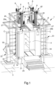
Figure 1 is an axonometric view of the booth according to the invention in the operating configuration; -
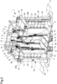
Figure 2 is an axonometric view of the booth according to the invention in the operating configuration; -
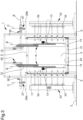
Figure 3 is a side cross-sectional view of the booth shown inFigure 2 ; -
Figure 4 is a side cross-sectional view of the booth shown inFigure 1 ; -
Figures 5 and 6 are exploded axonometric views of some elements of the booth according to the invention; -
Figure 7 is a top view of some booth components according to the invention; -
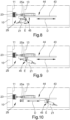
Figures 8, 9 and 10 are cross-sectional views showing some movement steps of some booth components shown inFigure 7 . - With particular reference to these figures,
reference numeral 1 globally indicates a spraying booth. - The
booth 1 comprises: - at least one
spraying compartment 4 adapted to house the work phases for the spraying of products to be coated and open at the top to define an access opening 5 to the booth itself; - at least one supporting
frame - cleaning means 29 mounted on the supporting
frame compartment 4; - movement means 40, placed between the supporting
frame compartment 4, and at least one operating configuration, wherein the cleaning means 29 are arranged inside thecompartment 4 through the access opening 5. - For ease of understanding of the figures, the cleaning means 29 are not shown in
Figures 1-6 , but are shown in detail inFigures 7-10 . - Advantageously, the supporting
frame stable resting surface 3, i.e., a substantially horizontal flat surface, such as e.g. the ground, as shown inFigure 1 . - Preferably, the supporting
frame resting element 6 on thestable resting surface 3 of the type of an elongated body extending, in use, vertically. - Conveniently, the supporting
frame resting elements 6 and each defining a corresponding fixed resting point on thestable resting surface 3. - This way, the resting
elements 6 are outside thecompartment 4 of thespraying booth 1. - The supporting
frame cross member 7, which extends at least partly above thespraying compartment 4 and facing at least partly the access opening 5. - Advantageously, the cleaning means 29 are mounted on the
cross member 7 above thespraying compartment 4 and facing the access opening 5. - The movement means 40 make the cleaning means 29 vertically movable between the home configuration and the operating configuration.
- Conveniently, the
spraying compartment 4 comprises abedplate 31 opposite the access opening 5. - In addition, the
spraying compartment 4 comprises aside wall 10, which extends from thebedplate 31 to end up at the point where theaccess opening 5 is located. This way, theside wall 10 and thebedplate 31 define aspraying compartment 4 of substantially hollow shape. - In particular, the
spraying compartment 4 comprises one ormore slits 32, cut through theside wall 10 and adapted to allow the insertion of suitable spraying means 33 into thecompartment 4. - Advantageously, the
spraying compartment 4 comprises at least oneaccess port 2 formed on theside wall 10 adapted, e.g., to allow the insertion/removal into/out of thespraying compartment 4 of at least one product to be coated. - Preferably, the
booth 1 comprises closing/opening means, not shown in the figures, of theaccess port 2. - In particular, the closing/opening means comprise at least one clamping body coupled in a movable manner to the
spraying compartment 4 close to theaccess port 2, by sealing it, in the operating configuration, and away from theaccess port 2, by releasing it, in the home configuration. - Conveniently, the movement means 40 comprise at least one
holding boom 8 of the cleaning means 29, mounted movable along a direction of movement A on the supportingframe spraying compartment 4, if in the operating configuration, and completely outside thespraying compartment 4, if in the home configuration. - This way, the cleaning means 29 are moved inside the
spraying compartment 4 through the access opening 5. - Advantageously, the movement means 40 comprise guidance means 15, 16, 17 of the
holding boom 8 along the direction of movement A, inside and outside of thespraying booth 1. - Furthermore, the movement means 40 comprise actuator means 18, 19, 20, 35, 36, 37, which are adapted to move the
holding boom 8 along the direction of movement A. - Preferably, the
holding boom 8 extends vertically along the direction of movement A. - In addition, the
holding boom 8 has a substantially elongated shape along the direction of movement A, so as to reduce the clearance of the same inside thespraying compartment 4. - In particular, the
holding boom 8 is mounted on thecross member 7, which extends substantially horizontally above the access opening 5, as shown inFigures 3 and4 . In particular, theholding boom 8 is a telescopic boom, extending inside thecompartment 4 along the direction of movement A, in an operating configuration, and retracted outside thecompartment 4 along the direction of movement A, in the home configuration. - This solution significantly reduces the vertical overhead clearance of the
holding boom 8 above thespraying booth 1 in the home configuration. - In more detail, the
holding boom 8 comprises: - at least a
first stretch 12, mounted movable in a sliding manner along the direction of movement A on the supportingframe - at least a
second stretch 13, coupled movable in a sliding manner along the direction of movement A to thefirst stretch 12. - In other words, the
second stretch 13 is mounted on thefirst stretch 12 and is made integral by shifting with the latter and following the movement thereof along a predefined first stroke of thefirst stretch 12 with respect to the supportingframe - In addition, the
second stretch 13 is movable with respect to thefirst stretch 12 along a second predefined stroke. - Thus, the total extension of the holding
boom 8 is defined by the sum of the first stroke and of the second stroke. - Conveniently, the guidance means 15, 16, 17 comprise a first
rectilinear guide 15, positioned between the supportingframe first stretch 12, and the actuator means 18, 19, 20, 35, 36, 37 comprise afirst actuator assembly frame first stretch 12 to move the latter along the firstrectilinear guide 15. - Similarly, the guidance means 15, 16, 17 comprise a second
rectilinear guide 16, positioned between the first stretch and thesecond stretch second actuator assembly second stretch rectilinear guide 16. - Advantageously, the first stretch and the
second stretch - The two stretches 12, 13 have substantially the same length, but alternative embodiments, wherein they have different lengths, cannot be ruled out. Advantageously, the holding
boom 8 comprises at least oneintermediate stretch 14, which is positioned between the first stretch and thesecond stretch - In particular, the
intermediate stretch 14 is arranged juxtaposed and substantially parallel to the two stretches 12, 13, in the home configuration, and substantially aligned longitudinally to the two stretches 12, 13 along the direction of movement A, in the operating configuration. - This way, the maximum extension of the holding
boom 8 is further increased by the stroke of theintermediate stretch 14, similarly to what described above with respect to the first stretch and thesecond stretch - Furthermore, in the home configuration, the
intermediate stretch 14 keeps the clearance of the holdingboom 8 small, i.e., it does not increase its vertical overhead clearance above thebooth 1. - Advantageously, the guidance means 15, 16, 17 comprise an intermediate
rectilinear guide 17, positioned between theintermediate stretch 14 and one of either thefirst stretch 12 or thesecond stretch 13. - The second
rectilinear guide 16 is positioned between theintermediate stretch 14 and the other of either thefirst stretch 12 or thesecond stretch 13. - Similarly, the actuator means 18, 19, 20, 35, 36, 37 comprise an
intermediate actuator assembly intermediate stretch 14, thefirst stretch 12, or thesecond stretch 13. - Moreover, further embodiments cannot be ruled out wherein the holding
boom 8 comprises a plurality ofintermediate stretches 14 coupled movable and sliding along the direction of movement A to each other, by interposition of respective intermediaterectilinear guides 17, and movable along the same by means of respectiveintermediate actuator assemblies - Such embodiments would allow the maximum extension of the holding
boom 8 to be further increased. - Preferably, the first stretch and the
second stretch intermediate stretch 14. - Embodiments of the booth cannot however be ruled out wherein at least one of either the first, the second or the intermediate stretches 12, 13, 14 is longer than at least one of the other stretches 12, 13, 14.
- Preferably, the
stretches spraying compartment 4. - According to the embodiment of the holding
boom 8 shown in the figures, thefirst actuator assembly first actuator 18, mounted on the supportingframe 6, and afirst rack 35, associated with thefirst stretch 12 along the direction of movement A and mechanically coupled to thefirst actuator 18. - The
intermediate actuator assembly intermediate actuator 20, mounted on thesecond stretch 13, and anintermediate rack 37, associated with theintermediate stretch 14 along the direction of movement A and mechanically coupled to theintermediate actuator 20. - The
second actuator assembly second actuator 19, coinciding with theintermediate actuator 20, and asecond rack 36, associated with thefirst stretch 12 along the direction of movement A and mechanically coupleable to theintermediate actuator 20. - In particular, the
intermediate actuator 20 comprises afirst gear wheel 38, mechanically coupleable to thesecond rack 36, and asecond gear wheel 39, mechanically coupleable to theintermediate rack 37, as shown inFigures 5 and 6 . This way, in the switch from the operating configuration to the home configuration, theintermediate actuator 20 engages theintermediate rack 37 and moves thesecond stretch 13 facing theintermediate stretch 14, until it allows thesecond gear wheel 39 to engage thesecond rack 36 and move thesecond stretch 13 facing thefirst stretch 12. - In particular, the movement means 40 comprise securing means, not shown in the figures, of the
second stretch 13 to theintermediate stretch 14. - The securing means are configured to secure the
intermediate stretch 14 to thesecond stretch 13 during the movement of the holdingboom 8 from the operating configuration to the home configuration, i.e., during the ascent of thesecond stretch 13, to also move theintermediate stretch 14 facing thefirst stretch 12. - Conveniently, the movement means 40 comprise a plurality of holding
booms 8. - Furthermore, the movement means 40 comprise guidance means 15, 16, 17 and actuator means 18, 19, 20, 35, 36, 37 in the same number as the holding
booms 8. Preferably, the holdingbooms 8 are arranged at the same height and at predefined positions corresponding to the vertices of a square. - Advantageously, the supporting
frame cross members 7 extending vertically parallel to each other above theaccess opening 5, on eachcross member 7 being mounted a pair of holdingbooms 8, as shown inFigure 2 . - Conveniently, the cleaning means 29 comprise at least one
cleaning device spraying compartment 4, selected from the list comprising apneumatic dispensing device 21, a hydraulic dispensing device and an absorbingelement 23. - Preferably, the
pneumatic dispensing device 21 is of the type of a dispenser provided with at least one nozzle through which a pressurized air stream is delivered. - The hydraulic dispensing device, on the other hand, is preferably of the type of a dispenser provided with at least one nozzle through which at least one liquid cleaning solution is delivered.
- In the remainder of the following disclosure, the characteristics relating to the
pneumatic dispensing device 21 are to be considered valid also for the hydraulic dispensing device, since the only difference between these devices lies in the nature of the fluid delivered. - In addition, the absorbing
element 23 is of the type of a sponge, a cloth, or the like. Preferably, the absorbingelement 23 is a sponge. - Preferably, the
pneumatic dispensing device 21 is angled downwards, so as to direct the air stream abutting against the vertical walls of thecompartment 4 towards thebedplate 31 and not towards theaccess opening 5. - Advantageously, the
spraying booth 1 comprises suction means 24, that are arranged at the point where thebedplate 31 of the booth itself is located and that are adapted to extract the fluids present inside thespraying compartment 4. - This way, in the operating configuration of the cleaning means 29, any fluid inside the
spraying compartment 4 is extracted by the suction means 24, thus preventing it from exiting through theaccess opening 5. - Preferably, the suction means 24 coincide with the suction means used for the suction of the paint during the coating steps.
- Preferably, the cleaning means 29 comprise a plurality of hydraulic dispensing devices, a plurality of pneumatic dispensing devices, and a plurality of absorbing
elements 23, each arranged to operate on a predefined portion of thespraying compartment 4, to intervene substantially on the entire perimeter of the compartment itself. - In the exemplary case of the
interior surface 11, when switching from the home configuration to the operating configuration, thecleaning devices spraying compartment 4, by cleaning the entire surface extension of theinterior surface 11. - More in detail, the
pneumatic dispensing device 21 is arranged at a lower height than the absorbingelement 23. - Thus, when switching from the home configuration to the operating configuration, the absorbing
element 23 slides in contact with the interior surfaces of thespraying compartment 4 to follow thepneumatic dispensing device 21. - Advantageously, the movement means 40 comprise at least one holding
frame boom 8. - At least one
cleaning device frame spraying compartment 4, thus cleaning it. - Advantageously, the holding
frame second stretch 13. - Preferably, the holding
frame - With particular reference to
Figure 8 , the holdingframe element 25a, associated with a pair ofsecond stretches 13, and a second supportingelement 25b, associated with another pair ofsecond stretches 13, to substantially define a holdingframe spraying compartment 4 along its entire perimeter. - Further embodiments cannot, however, be ruled out, wherein the holding
frame second stretch 13 of each holdingboom 8 and comprises four connecting elements, which are positioned between corresponding pairs of holdingbooms 8 respectively, to make a substantiallycontinuous holding frame - Conveniently, the
cleaning devices elements interior surface 11. - Advantageously, the holding
frame vacuous portion 41, which allows the passage of external elements, arranged inside thespraying compartment 4, such as e.g. paint dispensers or the like. - In particular, the holding
frame vacuous portion 41, at the point where the first supportingelement 25a is located, and at least onevacuous portion 41, at the point where the second supportingelement 25b is located, as shown inFigure 8 . - Further embodiments cannot however be ruled out, wherein the holding
frame vacuous portions 41, such as e.g. a pair ofvacuous portions 41 at the point where each supportingelement - Advantageously, the
booth 1 comprises operating means 42 of the cleaning means 29 configured to activate/deactivate at least one of thecleaning devices - In particular, the operating means 42 comprise at least one operating assembly, not shown in the figures, positioned between the holding
frame element 23 and configured to move the absorbingelement 23 close to theside wall 10, in order to abut against theinterior surface 11, and away from theside wall 10. - This way, in the operating configuration, the operating assembly moves the absorbing
element 23 to abut against theinterior surface 11. - This solution allows the absorbing
element 23 to slide in contact with theinterior surface 11, thus absorbing any liquids and/or paint residue present thereon. - Advantageously, the
booth 1 comprises displacement means 44, 45 of at least one of thecleaning device cleaning device side wall 10, and at least a second configuration of use, wherein the cleaning device faces thebedplate 31. - The displacement means 44, 45 comprise at least one
rotation assembly 45 of thecleaning device - The displacement means 44, 45 also comprise at least one
longitudinal movement assembly 44 of thecleaning device bedplate 31. - Preferably, the axis of rotation E is transverse with respect to the direction of displacement D.
- In particular, the axis of rotation E is orthogonal with respect to the direction of displacement D.
- Conveniently, the
rotation assembly 45 is positioned between at least onecleaning device longitudinal movement assembly 44 is positioned between the longitudinal movement means 44 and therotation assembly 45. - Preferably, the
longitudinal movement assembly 44 is positioned between at least oneholding boom 8 and therotation assembly 45. - Further embodiments of the displacement means 44, 45 cannot be ruled out, wherein the
longitudinal movement assembly 44 is positioned between the holdingframe rotation assembly 45. - This way, in the second configuration of use, the
longitudinal movement assembly 44 moves thecleaning device bedplate 31. - Advantageously, the
longitudinal movement assembly 44 comprises at least oneguidance assembly 43 which extends longitudinally along the direction of displacement D and therotation assembly 45 is coupled in a sliding manner along theguidance assembly 43. - This way, in the second configuration of use, the
rotation assembly 45 is moved integral together with thecleaning device - This solution allows the
cleaning device bedplate 31. - Preferably, the
cleaning device pneumatic dispensing device 21. Advantageously, the displacement means 44, 45 are configured to move a plurality ofpneumatic dispensing devices 21 arranged aligned with each other along a direction of arrangement substantially parallel to the axis of rotation E. - This way, in the second configuration of use, the
cleaning devices bedplate 31. - Furthermore, further embodiments of the
pneumatic dispensing device 21 cannot be ruled out, wherein the same comprises a plurality of dispensers arranged aligned with each other along a direction of positioning substantially parallel to the axis of rotation E. - This way, the displacement means 44, 45 move along the direction of displacement D an
individual cleaning device bedplate 31. - In particular, the
booth 1 comprises a pair of displacement means 44, 45 arranged substantially opposite each other. - This way, in the second configuration of use, the
longitudinal movement assemblies 44 move therespective cleaning devices Figures 7-10 . - This solution allows the cleaning device(s) 21, 23 of each displacement means 44, 45 to explore half the extension of the
bedplate 31. - Advantageously, each displacement means 44, 45 is associated with a
corresponding holding boom 8. - Conveniently, the
booth 1 comprises fastening means 26, 27, 28a, 28b provided with: - at least one
closure body access opening 5, adapted to close thespraying compartment 4; - shifting means 26, 27 of the
closure body access opening 5, closing it in the home configuration, and moving away from theaccess opening 5, releasing it in the operating configuration, in such a way as to insert the cleaning means 29 inside thespraying compartment 4. - Preferably, in the home configuration of the cleaning means 29, the
closure body spraying compartment 4 at the point where theaccess opening 5 is located, by hermetically closing and sealing it. - In particular, the
closure body frame access opening 5. - Advantageously, the shifting means 26, 27 comprise at least one of:
- at least one
horizontal shifting unit 26 of theclosure body - at least one
vertical shifting unit 27 of theclosure body - Conveniently, the
closure body - In addition, the
closure body access opening 5. - In particular, the
closure body horizontal shifting unit 26 and horizontally movable along the direction of horizontal shift B, to switch from the home configuration to the operating configuration and vice versa. - This way, the horizontal shift of the
closure body access opening 5. - More in detail, the
closure body movable leaves - Preferably, the shifting means 26, 27 comprise both the
horizontal shifting unit 26 and thevertical shifting unit 27. - This way, the
leaves spraying compartment 4 in the operating configuration and in the home configuration, respectively. - The operation of the
booth 1 is as follows. - Before starting a new coating cycle using paints of a different color with respect to the previous coating cycle, it is necessary to carry out a cleaning cycle of the booth. Therefore, the movement means 40 move the
closure body spraying compartment 4. - In detail, the
vertical shifting unit 27 vertically moves theclosure body compartment 4, vertically spacing theclosure body access opening 5. - Next, the
horizontal shifting unit 26 horizontally moves theclosure body access opening 5. - In particular, the
horizontal shifting unit 26 moves theleaves access opening 5, by releasing it. - In such a configuration, the movement means 40 move the cleaning means 29 inside the
spraying compartment 4. - In particular, the actuator means 18, 19, 20, 35, 36, 37 move the
stretches booms 8 inside thespraying compartment 4 and reaching the operating configuration. - When the cleaning of the
spraying compartment 4 is completed, the movement means 40 take theholding booms 8 out of the compartment itself. - In particular, each holding
boom 8 is retracted on itself to juxtapose, facing each other, thestretches Figure 4 . - After this configuration has been reached, the shifting means 26, 27 bring the
closure body spraying compartment 4. - Preferably, the
booth 1 comprises spraying means 33 provided with one ormore spraying devices 34 insertable in the corresponding slits 32. - It has in practice been ascertained that the described invention achieves the intended objects.
- In particular, the fact should be noted that the vertically elongated shape of the holding boom considerably reduces the clearance inside the spraying booth in the operating configuration.
- In addition, the telescopic structure defined by the coupling of the first stretch, the second stretch and the intermediate stretch significantly reduces the clearance of the holding boom in the home configuration.
- These measures make the use of the cleaning means fully automated, simple and fast.
- It should also be pointed out that the technical characteristics of the movement means and of the cleaning means described above help to considerably reduce and simplify the technical and structural complexity of the spraying booth as a whole.
Claims (10)
- Spraying booth (1), comprising:- at least one spraying compartment (4), adapted to house the work phases for the spraying of products to be painted and open at the top, to define an access opening (5) to the booth itself;- at least one supporting frame (6, 7);- cleaning means (29) mounted on said supporting frame (6, 7) and adapted to clean the inside of said compartment (4);- movement means (40), placed between said supporting frame (6, 7) and said cleaning means (29), adapted to move the latter between a home configuration, wherein said cleaning means (29) are arranged outside said compartment (4), and at least one operating configuration, wherein said cleaning means (29) are arranged inside said compartment (4) through the access opening (5);wherein said movement means (40) comprise at least one holding boom (8) of said cleaning means (29), mounted movable along a direction of movement (A) on said supporting frame (6, 7), arranged at least partly inside said spraying compartment (4), in said operating configuration, and outside said spraying compartment (4), in the home configuration;characterized by the fact that said holding boom (8) is a telescopic boom, extending inside said spraying compartment (4) along said direction of movement (A), in said operating configuration, and retracted outside said spraying compartment (4) along said direction of movement (A), in said home configuration.
- Booth (1) according to claim 1, characterized by the fact that said holding boom (8) comprises:- at least a first stretch (12), mounted movable in a sliding manner along said direction of movement (A) on said supporting frame (6, 7);- at least a second stretch (13), coupled movable in a sliding manner along said direction of movement (A) to said first stretch (12);said first and said second stretches (12, 13) being substantially placed juxtaposed and parallel to each other, in said home configuration, and being moved away and arranged substantially aligned to each other along said direction of movement (A), in said operating configuration.
- Booth (1) according to one or more of the preceding claims, characterized by the fact that said holding boom (8) comprises at least one intermediate stretch (14), placed between said first and said second stretch (12, 13) and coupled movable in a sliding manner to the latter along said direction of movement (A), said intermediate stretch (14) being placed substantially juxtaposed and parallel to said first and said second stretches (12, 13), in said home configuration, and substantially aligned with said first and said second stretch (12, 13) along said direction of movement (A), in said operating configuration.
- Booth (1) according to one or more of the preceding claims, characterized by the fact that said movement means (40) comprise a plurality of said holding booms (8).
- Booth (1) according to one or more of the preceding claims, characterized by the fact that said cleaning means (29) comprise at least one cleaning device (21, 23) of said spraying compartment (4), selected from the list comprising a pneumatic dispensing device (21), a hydraulic dispensing device, an absorbing element (23).
- Booth (1) according to one or more of the preceding claims, characterized by the fact that said cleaning means (29) comprise a plurality of said cleaning devices (21,23).
- Booth (1) according to one or more of the preceding claims, characterized by the fact that:- said movement means (40) comprise at least one holding frame (25a, 25b), associated with at least one holding boom (8);- said at least one cleaning device (21, 23) is mounted on said holding frame (25a, 25b) and in said operating configuration is placed facing and/or in contact with said spraying compartment (4), cleaning it.
- Booth (1) according to one or more of the preceding claims, characterized by the fact that:- said spraying compartment (4) comprises at least one bedplate (31) opposite said access opening (5) and at least one side wall (10) extending from the bedplate (31) to end up at the point where said access opening (5) is located;- it comprises displacement means (44, 45) of at least one of said cleaning devices (21, 23) between at least a first configuration of use, wherein said at least one cleaning device (21, 23) faces said side wall (10), and at least a second configuration of use, wherein said at least one cleaning device (21, 23) faces said bedplate (31).
- Booth (1) according to one or more of the preceding claims, characterized by the fact that it comprises fastening means (26, 27, 28a, 28b) of said spraying compartment (4), provided with:- at least one closure body (28a, 28b) of said access opening (5), adapted to close said spraying compartment (4);- shifting means (26, 27) of the closure body (28a, 28b) approaching said access opening (5), closing it in said home configuration, and moving away from said access opening (5), releasing it, in said operating configuration, in such a way as to insert said cleaning means (29) inside said spraying compartment (4).
- Booth (1) according to one or more of the preceding claims, characterized by the fact that said shifting means (26, 27) comprise at least one of:- at least one horizontal shifting unit (26) of said closure body (28a, 28b) along a direction of horizontal shift (B);- at least one vertical shifting unit (27) of said closure body (28a, 28b) along a direction of vertical shift (C), substantially transverse to said direction of horizontal shift (B).
Applications Claiming Priority (2)
| Application Number | Priority Date | Filing Date | Title |
|---|---|---|---|
| IT102020000007318A IT202000007318A1 (en) | 2020-04-06 | 2020-04-06 | PAINTING BOOTH |
| PCT/IB2021/052610 WO2021205284A1 (en) | 2020-04-06 | 2021-03-30 | Spraying booth |
Publications (2)
| Publication Number | Publication Date |
|---|---|
| EP4132726A1 EP4132726A1 (en) | 2023-02-15 |
| EP4132726B1 true EP4132726B1 (en) | 2024-05-08 |
Family
ID=71094720
Family Applications (1)
| Application Number | Title | Priority Date | Filing Date |
|---|---|---|---|
| EP21722283.5A Active EP4132726B1 (en) | 2020-04-06 | 2021-03-30 | Spraying booth |
Country Status (3)
| Country | Link |
|---|---|
| EP (1) | EP4132726B1 (en) |
| IT (1) | IT202000007318A1 (en) |
| WO (1) | WO2021205284A1 (en) |
Families Citing this family (2)
| Publication number | Priority date | Publication date | Assignee | Title |
|---|---|---|---|---|
| CN114570544B (en) * | 2022-03-15 | 2023-06-06 | 广德众泰科技有限公司 | Spraying device and spraying method for circuit board production |
| CN114798261A (en) * | 2022-04-28 | 2022-07-29 | 内蒙古工业大学 | Multi-angle spraying device based on six arms |
Citations (1)
| Publication number | Priority date | Publication date | Assignee | Title |
|---|---|---|---|---|
| EP3341133B1 (en) * | 2015-08-24 | 2020-09-09 | Siver S.r.l. | Coating booth |
Family Cites Families (1)
| Publication number | Priority date | Publication date | Assignee | Title |
|---|---|---|---|---|
| US7665414B2 (en) * | 2005-09-19 | 2010-02-23 | Nordson Corporation | Powder coating booth |
-
2020
- 2020-04-06 IT IT102020000007318A patent/IT202000007318A1/en unknown
-
2021
- 2021-03-30 EP EP21722283.5A patent/EP4132726B1/en active Active
- 2021-03-30 WO PCT/IB2021/052610 patent/WO2021205284A1/en not_active Ceased
Patent Citations (1)
| Publication number | Priority date | Publication date | Assignee | Title |
|---|---|---|---|---|
| EP3341133B1 (en) * | 2015-08-24 | 2020-09-09 | Siver S.r.l. | Coating booth |
Also Published As
| Publication number | Publication date |
|---|---|
| WO2021205284A1 (en) | 2021-10-14 |
| IT202000007318A1 (en) | 2021-10-06 |
| EP4132726A1 (en) | 2023-02-15 |
Similar Documents
| Publication | Publication Date | Title |
|---|---|---|
| EP4132726B1 (en) | Spraying booth | |
| EP2698232B1 (en) | Painting device | |
| US8453597B2 (en) | Paint shop and corresponding method of operation | |
| EP3012032B1 (en) | Robot with a cleaning device and associated operating method | |
| DE60125369T2 (en) | METHOD AND STATION FOR REPLACING LIQUID FOR A SPRAYING SYSTEM | |
| US9694378B2 (en) | Application robot having a connection unit for different applicators | |
| KR102207462B1 (en) | Size-variable Painting Booth capable of Manufacturing in Small Quantity Batch Production | |
| KR20150036821A (en) | Coating system and method for the series coating of workpieces | |
| EP2658660A1 (en) | Paint booth for painting plants for products | |
| EP3341133B1 (en) | Coating booth | |
| KR20030024910A (en) | Method and device for filling a paint reservoir in an automated painting installation | |
| CN107442343A (en) | A kind of multiaxis spray-painting plant | |
| DE102010024538A1 (en) | paint shop | |
| CN209662904U (en) | A kind of high pressure water-vapour spraying device of dust suppression equipment | |
| DE19722773C1 (en) | Booth for powder coating | |
| US9751103B2 (en) | Varnishing plant for body shops | |
| CN116116598B (en) | Switchable automotive interior spare paint spraying apparatus | |
| CN214864769U (en) | Spraying device is used in sheet metal component production | |
| RU2712570C1 (en) | Spray system | |
| CN216826845U (en) | Paint spraying apparatus is used in fire-fighting equipment production | |
| CN103990573A (en) | Powder spray booth capable of achieving position change and deformation | |
| KR102004728B1 (en) | Painting device for the finish of the powder coating | |
| CN204842061U (en) | Machine is spouted to hanging incasement row in top | |
| WO2021124178A1 (en) | Painting booth with manual filter-changing system | |
| KR19990002784U (en) | Grating device for maintenance work in automotive spray spray booth |
Legal Events
| Date | Code | Title | Description |
|---|---|---|---|
| STAA | Information on the status of an ep patent application or granted ep patent |
Free format text: STATUS: UNKNOWN |
|
| STAA | Information on the status of an ep patent application or granted ep patent |
Free format text: STATUS: THE INTERNATIONAL PUBLICATION HAS BEEN MADE |
|
| PUAI | Public reference made under article 153(3) epc to a published international application that has entered the european phase |
Free format text: ORIGINAL CODE: 0009012 |
|
| STAA | Information on the status of an ep patent application or granted ep patent |
Free format text: STATUS: REQUEST FOR EXAMINATION WAS MADE |
|
| 17P | Request for examination filed |
Effective date: 20221102 |
|
| AK | Designated contracting states |
Kind code of ref document: A1 Designated state(s): AL AT BE BG CH CY CZ DE DK EE ES FI FR GB GR HR HU IE IS IT LI LT LU LV MC MK MT NL NO PL PT RO RS SE SI SK SM TR |
|
| DAV | Request for validation of the european patent (deleted) | ||
| DAX | Request for extension of the european patent (deleted) | ||
| P01 | Opt-out of the competence of the unified patent court (upc) registered |
Effective date: 20230527 |
|
| GRAP | Despatch of communication of intention to grant a patent |
Free format text: ORIGINAL CODE: EPIDOSNIGR1 |
|
| STAA | Information on the status of an ep patent application or granted ep patent |
Free format text: STATUS: GRANT OF PATENT IS INTENDED |
|
| INTG | Intention to grant announced |
Effective date: 20231019 |
|
| GRAJ | Information related to disapproval of communication of intention to grant by the applicant or resumption of examination proceedings by the epo deleted |
Free format text: ORIGINAL CODE: EPIDOSDIGR1 |
|
| STAA | Information on the status of an ep patent application or granted ep patent |
Free format text: STATUS: REQUEST FOR EXAMINATION WAS MADE |
|
| GRAS | Grant fee paid |
Free format text: ORIGINAL CODE: EPIDOSNIGR3 |
|
| STAA | Information on the status of an ep patent application or granted ep patent |
Free format text: STATUS: GRANT OF PATENT IS INTENDED |
|
| GRAP | Despatch of communication of intention to grant a patent |
Free format text: ORIGINAL CODE: EPIDOSNIGR1 |
|
| INTC | Intention to grant announced (deleted) | ||
| INTG | Intention to grant announced |
Effective date: 20240305 |
|
| GRAA | (expected) grant |
Free format text: ORIGINAL CODE: 0009210 |
|
| STAA | Information on the status of an ep patent application or granted ep patent |
Free format text: STATUS: THE PATENT HAS BEEN GRANTED |
|
| AK | Designated contracting states |
Kind code of ref document: B1 Designated state(s): AL AT BE BG CH CY CZ DE DK EE ES FI FR GB GR HR HU IE IS IT LI LT LU LV MC MK MT NL NO PL PT RO RS SE SI SK SM TR |
|
| REG | Reference to a national code |
Ref country code: GB Ref legal event code: FG4D |
|
| REG | Reference to a national code |
Ref country code: CH Ref legal event code: EP |
|
| REG | Reference to a national code |
Ref country code: DE Ref legal event code: R096 Ref document number: 602021013086 Country of ref document: DE |
|
| REG | Reference to a national code |
Ref country code: IE Ref legal event code: FG4D |
|
| REG | Reference to a national code |
Ref country code: LT Ref legal event code: MG9D |
|
| REG | Reference to a national code |
Ref country code: NL Ref legal event code: MP Effective date: 20240508 |
|
| PG25 | Lapsed in a contracting state [announced via postgrant information from national office to epo] |
Ref country code: IS Free format text: LAPSE BECAUSE OF FAILURE TO SUBMIT A TRANSLATION OF THE DESCRIPTION OR TO PAY THE FEE WITHIN THE PRESCRIBED TIME-LIMIT Effective date: 20240908 |
|
| PG25 | Lapsed in a contracting state [announced via postgrant information from national office to epo] |
Ref country code: BG Free format text: LAPSE BECAUSE OF FAILURE TO SUBMIT A TRANSLATION OF THE DESCRIPTION OR TO PAY THE FEE WITHIN THE PRESCRIBED TIME-LIMIT Effective date: 20240508 |
|
| PG25 | Lapsed in a contracting state [announced via postgrant information from national office to epo] |
Ref country code: FI Free format text: LAPSE BECAUSE OF FAILURE TO SUBMIT A TRANSLATION OF THE DESCRIPTION OR TO PAY THE FEE WITHIN THE PRESCRIBED TIME-LIMIT Effective date: 20240508 Ref country code: HR Free format text: LAPSE BECAUSE OF FAILURE TO SUBMIT A TRANSLATION OF THE DESCRIPTION OR TO PAY THE FEE WITHIN THE PRESCRIBED TIME-LIMIT Effective date: 20240508 |
|
| PG25 | Lapsed in a contracting state [announced via postgrant information from national office to epo] |
Ref country code: GR Free format text: LAPSE BECAUSE OF FAILURE TO SUBMIT A TRANSLATION OF THE DESCRIPTION OR TO PAY THE FEE WITHIN THE PRESCRIBED TIME-LIMIT Effective date: 20240809 |
|
| PG25 | Lapsed in a contracting state [announced via postgrant information from national office to epo] |
Ref country code: PT Free format text: LAPSE BECAUSE OF FAILURE TO SUBMIT A TRANSLATION OF THE DESCRIPTION OR TO PAY THE FEE WITHIN THE PRESCRIBED TIME-LIMIT Effective date: 20240909 |
|
| REG | Reference to a national code |
Ref country code: AT Ref legal event code: MK05 Ref document number: 1684568 Country of ref document: AT Kind code of ref document: T Effective date: 20240508 |
|
| PG25 | Lapsed in a contracting state [announced via postgrant information from national office to epo] |
Ref country code: NL Free format text: LAPSE BECAUSE OF FAILURE TO SUBMIT A TRANSLATION OF THE DESCRIPTION OR TO PAY THE FEE WITHIN THE PRESCRIBED TIME-LIMIT Effective date: 20240508 |
|
| PG25 | Lapsed in a contracting state [announced via postgrant information from national office to epo] |
Ref country code: ES Free format text: LAPSE BECAUSE OF FAILURE TO SUBMIT A TRANSLATION OF THE DESCRIPTION OR TO PAY THE FEE WITHIN THE PRESCRIBED TIME-LIMIT Effective date: 20240508 |
|
| PG25 | Lapsed in a contracting state [announced via postgrant information from national office to epo] |
Ref country code: AT Free format text: LAPSE BECAUSE OF FAILURE TO SUBMIT A TRANSLATION OF THE DESCRIPTION OR TO PAY THE FEE WITHIN THE PRESCRIBED TIME-LIMIT Effective date: 20240508 |
|
| PG25 | Lapsed in a contracting state [announced via postgrant information from national office to epo] |
Ref country code: PL Free format text: LAPSE BECAUSE OF FAILURE TO SUBMIT A TRANSLATION OF THE DESCRIPTION OR TO PAY THE FEE WITHIN THE PRESCRIBED TIME-LIMIT Effective date: 20240508 |
|
| PG25 | Lapsed in a contracting state [announced via postgrant information from national office to epo] |
Ref country code: LV Free format text: LAPSE BECAUSE OF FAILURE TO SUBMIT A TRANSLATION OF THE DESCRIPTION OR TO PAY THE FEE WITHIN THE PRESCRIBED TIME-LIMIT Effective date: 20240508 |
|
| PG25 | Lapsed in a contracting state [announced via postgrant information from national office to epo] |
Ref country code: PT Free format text: LAPSE BECAUSE OF FAILURE TO SUBMIT A TRANSLATION OF THE DESCRIPTION OR TO PAY THE FEE WITHIN THE PRESCRIBED TIME-LIMIT Effective date: 20240909 Ref country code: PL Free format text: LAPSE BECAUSE OF FAILURE TO SUBMIT A TRANSLATION OF THE DESCRIPTION OR TO PAY THE FEE WITHIN THE PRESCRIBED TIME-LIMIT Effective date: 20240508 Ref country code: NO Free format text: LAPSE BECAUSE OF FAILURE TO SUBMIT A TRANSLATION OF THE DESCRIPTION OR TO PAY THE FEE WITHIN THE PRESCRIBED TIME-LIMIT Effective date: 20240808 Ref country code: NL Free format text: LAPSE BECAUSE OF FAILURE TO SUBMIT A TRANSLATION OF THE DESCRIPTION OR TO PAY THE FEE WITHIN THE PRESCRIBED TIME-LIMIT Effective date: 20240508 Ref country code: LV Free format text: LAPSE BECAUSE OF FAILURE TO SUBMIT A TRANSLATION OF THE DESCRIPTION OR TO PAY THE FEE WITHIN THE PRESCRIBED TIME-LIMIT Effective date: 20240508 Ref country code: IS Free format text: LAPSE BECAUSE OF FAILURE TO SUBMIT A TRANSLATION OF THE DESCRIPTION OR TO PAY THE FEE WITHIN THE PRESCRIBED TIME-LIMIT Effective date: 20240908 Ref country code: HR Free format text: LAPSE BECAUSE OF FAILURE TO SUBMIT A TRANSLATION OF THE DESCRIPTION OR TO PAY THE FEE WITHIN THE PRESCRIBED TIME-LIMIT Effective date: 20240508 Ref country code: GR Free format text: LAPSE BECAUSE OF FAILURE TO SUBMIT A TRANSLATION OF THE DESCRIPTION OR TO PAY THE FEE WITHIN THE PRESCRIBED TIME-LIMIT Effective date: 20240809 Ref country code: FI Free format text: LAPSE BECAUSE OF FAILURE TO SUBMIT A TRANSLATION OF THE DESCRIPTION OR TO PAY THE FEE WITHIN THE PRESCRIBED TIME-LIMIT Effective date: 20240508 Ref country code: ES Free format text: LAPSE BECAUSE OF FAILURE TO SUBMIT A TRANSLATION OF THE DESCRIPTION OR TO PAY THE FEE WITHIN THE PRESCRIBED TIME-LIMIT Effective date: 20240508 Ref country code: BG Free format text: LAPSE BECAUSE OF FAILURE TO SUBMIT A TRANSLATION OF THE DESCRIPTION OR TO PAY THE FEE WITHIN THE PRESCRIBED TIME-LIMIT Effective date: 20240508 Ref country code: AT Free format text: LAPSE BECAUSE OF FAILURE TO SUBMIT A TRANSLATION OF THE DESCRIPTION OR TO PAY THE FEE WITHIN THE PRESCRIBED TIME-LIMIT Effective date: 20240508 Ref country code: RS Free format text: LAPSE BECAUSE OF FAILURE TO SUBMIT A TRANSLATION OF THE DESCRIPTION OR TO PAY THE FEE WITHIN THE PRESCRIBED TIME-LIMIT Effective date: 20240808 |
|
| PG25 | Lapsed in a contracting state [announced via postgrant information from national office to epo] |
Ref country code: DK Free format text: LAPSE BECAUSE OF FAILURE TO SUBMIT A TRANSLATION OF THE DESCRIPTION OR TO PAY THE FEE WITHIN THE PRESCRIBED TIME-LIMIT Effective date: 20240508 |
|
| PG25 | Lapsed in a contracting state [announced via postgrant information from national office to epo] |
Ref country code: EE Free format text: LAPSE BECAUSE OF FAILURE TO SUBMIT A TRANSLATION OF THE DESCRIPTION OR TO PAY THE FEE WITHIN THE PRESCRIBED TIME-LIMIT Effective date: 20240508 |
|
| PG25 | Lapsed in a contracting state [announced via postgrant information from national office to epo] |
Ref country code: CZ Free format text: LAPSE BECAUSE OF FAILURE TO SUBMIT A TRANSLATION OF THE DESCRIPTION OR TO PAY THE FEE WITHIN THE PRESCRIBED TIME-LIMIT Effective date: 20240508 |
|
| PG25 | Lapsed in a contracting state [announced via postgrant information from national office to epo] |
Ref country code: SK Free format text: LAPSE BECAUSE OF FAILURE TO SUBMIT A TRANSLATION OF THE DESCRIPTION OR TO PAY THE FEE WITHIN THE PRESCRIBED TIME-LIMIT Effective date: 20240508 Ref country code: RO Free format text: LAPSE BECAUSE OF FAILURE TO SUBMIT A TRANSLATION OF THE DESCRIPTION OR TO PAY THE FEE WITHIN THE PRESCRIBED TIME-LIMIT Effective date: 20240508 |
|
| PG25 | Lapsed in a contracting state [announced via postgrant information from national office to epo] |
Ref country code: SM Free format text: LAPSE BECAUSE OF FAILURE TO SUBMIT A TRANSLATION OF THE DESCRIPTION OR TO PAY THE FEE WITHIN THE PRESCRIBED TIME-LIMIT Effective date: 20240508 |
|
| PG25 | Lapsed in a contracting state [announced via postgrant information from national office to epo] |
Ref country code: SM Free format text: LAPSE BECAUSE OF FAILURE TO SUBMIT A TRANSLATION OF THE DESCRIPTION OR TO PAY THE FEE WITHIN THE PRESCRIBED TIME-LIMIT Effective date: 20240508 Ref country code: SK Free format text: LAPSE BECAUSE OF FAILURE TO SUBMIT A TRANSLATION OF THE DESCRIPTION OR TO PAY THE FEE WITHIN THE PRESCRIBED TIME-LIMIT Effective date: 20240508 Ref country code: RO Free format text: LAPSE BECAUSE OF FAILURE TO SUBMIT A TRANSLATION OF THE DESCRIPTION OR TO PAY THE FEE WITHIN THE PRESCRIBED TIME-LIMIT Effective date: 20240508 Ref country code: EE Free format text: LAPSE BECAUSE OF FAILURE TO SUBMIT A TRANSLATION OF THE DESCRIPTION OR TO PAY THE FEE WITHIN THE PRESCRIBED TIME-LIMIT Effective date: 20240508 Ref country code: DK Free format text: LAPSE BECAUSE OF FAILURE TO SUBMIT A TRANSLATION OF THE DESCRIPTION OR TO PAY THE FEE WITHIN THE PRESCRIBED TIME-LIMIT Effective date: 20240508 Ref country code: CZ Free format text: LAPSE BECAUSE OF FAILURE TO SUBMIT A TRANSLATION OF THE DESCRIPTION OR TO PAY THE FEE WITHIN THE PRESCRIBED TIME-LIMIT Effective date: 20240508 |
|
| REG | Reference to a national code |
Ref country code: DE Ref legal event code: R097 Ref document number: 602021013086 Country of ref document: DE |
|
| PLBE | No opposition filed within time limit |
Free format text: ORIGINAL CODE: 0009261 |
|
| STAA | Information on the status of an ep patent application or granted ep patent |
Free format text: STATUS: NO OPPOSITION FILED WITHIN TIME LIMIT |
|
| PGFP | Annual fee paid to national office [announced via postgrant information from national office to epo] |
Ref country code: DE Payment date: 20250327 Year of fee payment: 5 |
|
| 26N | No opposition filed |
Effective date: 20250211 |
|
| PG25 | Lapsed in a contracting state [announced via postgrant information from national office to epo] |
Ref country code: SI Free format text: LAPSE BECAUSE OF FAILURE TO SUBMIT A TRANSLATION OF THE DESCRIPTION OR TO PAY THE FEE WITHIN THE PRESCRIBED TIME-LIMIT Effective date: 20240508 |
|
| PGFP | Annual fee paid to national office [announced via postgrant information from national office to epo] |
Ref country code: BE Payment date: 20250327 Year of fee payment: 5 |
|
| PGFP | Annual fee paid to national office [announced via postgrant information from national office to epo] |
Ref country code: FR Payment date: 20250325 Year of fee payment: 5 |
|
| PGFP | Annual fee paid to national office [announced via postgrant information from national office to epo] |
Ref country code: GB Payment date: 20250327 Year of fee payment: 5 |
|
| PGFP | Annual fee paid to national office [announced via postgrant information from national office to epo] |
Ref country code: TR Payment date: 20250311 Year of fee payment: 5 |
|
| PGFP | Annual fee paid to national office [announced via postgrant information from national office to epo] |
Ref country code: IT Payment date: 20250331 Year of fee payment: 5 |
|
| PG25 | Lapsed in a contracting state [announced via postgrant information from national office to epo] |
Ref country code: SE Free format text: LAPSE BECAUSE OF FAILURE TO SUBMIT A TRANSLATION OF THE DESCRIPTION OR TO PAY THE FEE WITHIN THE PRESCRIBED TIME-LIMIT Effective date: 20240508 |
|
| PG25 | Lapsed in a contracting state [announced via postgrant information from national office to epo] |
Ref country code: MC Free format text: LAPSE BECAUSE OF FAILURE TO SUBMIT A TRANSLATION OF THE DESCRIPTION OR TO PAY THE FEE WITHIN THE PRESCRIBED TIME-LIMIT Effective date: 20240508 |
|
| REG | Reference to a national code |
Ref country code: CH Ref legal event code: H13 Free format text: ST27 STATUS EVENT CODE: U-0-0-H10-H13 (AS PROVIDED BY THE NATIONAL OFFICE) Effective date: 20251023 |
|
| PG25 | Lapsed in a contracting state [announced via postgrant information from national office to epo] |
Ref country code: LU Free format text: LAPSE BECAUSE OF NON-PAYMENT OF DUE FEES Effective date: 20250330 |
|
| PG25 | Lapsed in a contracting state [announced via postgrant information from national office to epo] |
Ref country code: CH Free format text: LAPSE BECAUSE OF NON-PAYMENT OF DUE FEES Effective date: 20250331 |
|
| PG25 | Lapsed in a contracting state [announced via postgrant information from national office to epo] |
Ref country code: IE Free format text: LAPSE BECAUSE OF NON-PAYMENT OF DUE FEES Effective date: 20250330 |