EP4132402B1 - Energiemodul mit zwei leistungsverstärkern - Google Patents
Energiemodul mit zwei leistungsverstärkern Download PDFInfo
- Publication number
- EP4132402B1 EP4132402B1 EP22714585.1A EP22714585A EP4132402B1 EP 4132402 B1 EP4132402 B1 EP 4132402B1 EP 22714585 A EP22714585 A EP 22714585A EP 4132402 B1 EP4132402 B1 EP 4132402B1
- Authority
- EP
- European Patent Office
- Prior art keywords
- module
- power amplifier
- power
- amplifier circuit
- energy
- Prior art date
- Legal status (The legal status is an assumption and is not a legal conclusion. Google has not performed a legal analysis and makes no representation as to the accuracy of the status listed.)
- Active
Links
Images


Classifications
-
- A—HUMAN NECESSITIES
- A61—MEDICAL OR VETERINARY SCIENCE; HYGIENE
- A61B—DIAGNOSIS; SURGERY; IDENTIFICATION
- A61B18/00—Surgical instruments, devices or methods for transferring non-mechanical forms of energy to or from the body
- A61B18/04—Surgical instruments, devices or methods for transferring non-mechanical forms of energy to or from the body by heating
- A61B18/12—Surgical instruments, devices or methods for transferring non-mechanical forms of energy to or from the body by heating by passing a current through the tissue to be heated, e.g. high-frequency current
- A61B18/1206—Generators therefor
-
- H—ELECTRICITY
- H03—ELECTRONIC CIRCUITRY
- H03F—AMPLIFIERS
- H03F1/00—Details of amplifiers with only discharge tubes, only semiconductor devices or only unspecified devices as amplifying elements
- H03F1/02—Modifications of amplifiers to raise the efficiency, e.g. gliding Class A stages, use of an auxiliary oscillation
- H03F1/0205—Modifications of amplifiers to raise the efficiency, e.g. gliding Class A stages, use of an auxiliary oscillation in transistor amplifiers
- H03F1/0277—Selecting one or more amplifiers from a plurality of amplifiers
-
- H—ELECTRICITY
- H02—GENERATION; CONVERSION OR DISTRIBUTION OF ELECTRIC POWER
- H02J—ELECTRIC POWER NETWORKS; CIRCUIT ARRANGEMENTS OR SYSTEMS FOR SUPPLYING OR DISTRIBUTING ELECTRIC POWER; SYSTEMS FOR STORING ELECTRIC ENERGY
- H02J3/00—Circuit arrangements for AC mains or AC distribution networks
- H02J3/007—Arrangements for selectively connecting one or more loads to one or more power sources or power lines
- H02J3/0075—Arrangements for selectively connecting one or more loads to one or more power sources or power lines for providing alternative feeding paths between load and source according to economic or energy efficiency considerations, e.g. economic dispatch
Definitions
- aspects of the ultrasonic surgical devices can be configured for transecting and/or coagulating tissue during surgical procedures, for example.
- aspects of the electrosurgical devices can be configured for transecting, coagulating, scaling, welding and/or desiccating tissue during surgical procedures, for example.
- the hub 106 may cause the visualization system 108 to display a snapshot of a surgical site, as recorded by an imaging device 124, on a non-sterile display 107 or 109, while maintaining a live feed of the surgical site on the primary display 119.
- the snapshot on the non-sterile display 107 or 109 can permit a non-sterile operator to perform a diagnostic step relevant to the surgical procedure, for example.
- a first communication module may be dedicated to shorter range wireless communications such as Wi-Fi and Bluetooth and a second communication module may be dedicated to longer range wireless communications such as GPS, EDGE, GPRS, CDMA, WiMAX, LTE, Ev-DO, and others.
- a microcontroller or controller is a system that integrates a microprocessor with peripheral circuits and memory.
- a microcontroller (or MCU for microcontroller unit) may be implemented as a small computer on a single integrated circuit. It may be similar to a SoC; a SoC may include a microcontroller as one of its components.
- a microcontroller may contain one or more core processing units (CPUs) along with memory and programmable input/output peripherals. Program memory in the form of Ferroelectric RAM, NOR flash or OTP ROM is also often included on chip, as well as a small amount of RAM.
- Microcontrollers may be employed for embedded applications, in contrast to the microprocessors used in personal computers or other general purpose applications consisting of various discrete chips.
- controller or microcontroller may be a stand-alone IC or chip device that interfaces with a peripheral device. This may be a link between two parts of a computer or a controller on an external device that manages the operation of (and connection with) that device.
- processors or microcontrollers described herein may be implemented by any single core or multicore processor such as those known under the trade name ARM Cortex by Texas Instruments.
- the processor may be an LM4F230H5QR ARM Cortex-M4F Processor Core, available from Texas Instruments, for example, comprising on-chip memory of 256 KB single-cycle flash memory, or other non-volatile memory, up to 40 MHz, a prefetch buffer to improve performance above 40 MHz, a 32 KB single-cycle serial random access memory (SRAM), internal read-only memory (ROM) loaded with StellarisWare ® software, 2 KB electrically erasable programmable read-only memory (EEPROM), one or more pulse width modulation (PWM) modules, one or more quadrature encoder inputs (QEI) analog, one or more 12-bit Analog-to-Digital Converters (ADC) with 12 analog input channels, details of which are available for the product datasheet.
- the processor may comprise a safety controller comprising two controller-based families such as TMS570 and RM4x known under the trade name Hercules ARM Cortex R4, also by Texas Instruments.
- the safety controller may be configured specifically for IEC 61508 and ISO 26262 safety critical applications, among others, to provide advanced integrated safety features while delivering scalable performance, connectivity, and memory options.
- Modular devices include the modules (as described in connection with FIG. 3 , for example) that are receivable within a surgical hub and the surgical devices or instruments that can be connected to the various modules in order to connect or pair with the corresponding surgical hub.
- the modular devices include, for example, intelligent surgical instruments, medical imaging devices, suction/irrigation devices, smoke evacuators, energy generators, ventilators, insufflators, and displays.
- the modular devices described herein can be controlled by control algorithms.
- the control algorithms can be executed on the modular device itself, on the surgical hub to which the particular modular device is paired, or on both the modular device and the surgical hub (e.g., via a distributed computing architecture).
- the modular devices' control algorithms control the devices based on data sensed by the modular device itself (i.e., by sensors in, on, or connected to the modular device). This data can be related to the patient being operated on (e.g., tissue properties or insufflation pressure) or the modular device itself (e.g., the rate at which a knife is being advanced, motor current, or energy levels).
- a control algorithm for a surgical stapling and cutting instrument can control the rate at which the instrument's motor drives its knife through tissue according to resistance encountered by the knife as it advances.
- the modular energy system 2000 is shown separate from the surgical instruments 2204, 2206, 2208 in one form, the modular energy system 2000 may be formed integrally with any of the surgical instruments 2204, 2206, 2208 to form a unitary surgical system.
- the modular energy system 2000 may be configured for wired or wireless communication.
- the modular energy system 2000 is configured to drive multiple surgical instruments 2204, 2206, 2208.
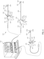
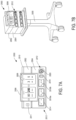
- the first surgical instrument is an ultrasonic surgical instrument 2204 and comprises a handpiece 2205 (HP), an ultrasonic transducer 2220, a shaft 2226, and an end effector 2222.
- the end effector 2222 comprises an ultrasonic blade 2228 acoustically coupled to the ultrasonic transducer 2220 and a clamp arm 2240.
- the handpiece 2205 comprises a trigger 2243 to operate the clamp arm 2240 and a combination of the toggle buttons 2234a, 2234b, 2234c to energize and drive the ultrasonic blade 2228 or other function.
- the toggle buttons 2234a, 2234b, 2234c can be configured to energize the ultrasonic transducer 2220 with the modular energy system 2000.
- the modular energy system 2000 also is configured to drive a second surgical instrument 2206.
- the second surgical instrument 2206 is an RF electrosurgical instrument and comprises a handpiece 2207 (HP), a shaft 2227, and an end effector 2224.
- the end effector 2224 comprises electrodes in clamp arms 2242a, 2242b and return through an electrical conductor portion of the shaft 2227.
- the electrodes are coupled to and energized by a bipolar energy source within the modular energy system 2000.
- the handpiece 2207 comprises a trigger 2245 to operate the clamp arms 2242a, 2242b and an energy button 2235 to actuate an energy switch to energize the electrodes in the end effector 2224.
- an "intelligent" device including control algorithms that respond to sensed data can be an improvement over a "dumb” device that operates without accounting for sensed data
- some sensed data can be incomplete or inconclusive when considered in isolation, i.e., without the context of the type of surgical procedure being performed or the type of tissue that is being operated on.
- the control algorithm may control the modular device incorrectly or sub optimally given the particular context-free sensed data.
- the optimal manner for a control algorithm to control a surgical instrument in response to a particular sensed parameter can vary according to the particular tissue type being operated on.
- the type of body cavity being operated in during an insufflation procedure can affect the function of a smoke evacuator.
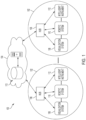
- a situationally aware surgical hub 2304 could determine whether the surgical site is under pressure (by determining that the surgical procedure is utilizing insufflation) and determine the procedure type. As a procedure type is generally performed in a specific body cavity, the surgical hub 2304 could then control the motor rate of the smoke evacuator appropriately for the body cavity being operated in. Thus, a situationally aware surgical hub 2304 could provide a consistent amount of smoke evacuation for both thoracic and abdominal procedures.
- data can be drawn from additional data sources 2326 to improve the conclusions that the surgical hub 2304 draws from one data source 2326.
- a situationally aware surgical hub 2304 could augment data that it receives from the modular devices 2302 with contextual information that it has built up regarding the surgical procedure from other data sources 2326.
- a situationally aware surgical hub 2304 can be configured to determine whether hemostasis has occurred (i.e., whether bleeding at a surgical site has stopped) according to video or image data received from a medical imaging device. However, in some cases the video or image data can be inconclusive.
- a situationally aware surgical hub 2304 could determine which step of the surgical procedure is being performed or will subsequently be performed and whether particular data or comparisons between data will be required for that step of the surgical procedure.
- the surgical hub 2304 can be configured to automatically call up data screens based upon the step of the surgical procedure being performed, without waiting for the surgeon to ask for the particular information.
- a situationally aware surgical hub 2304 could determine whether the operating theater is setup properly or optimally for the surgical procedure to be performed.
- the surgical hub 2304 can be configured to determine the type of surgical procedure being performed, retrieve the corresponding checklists, product location, or setup needs (e.g., from a memory), and then compare the current operating theater layout to the standard layout for the type of surgical procedure that the surgical hub 2304 determines is being performed.
- the surgical hub 2304 can be configured to compare the list of items for the procedure (scanned by a scanner, for example) and/or a list of devices paired with the surgical hub 2304 to a recommended or anticipated manifest of items and/or devices for the given surgical procedure. If there are any discontinuities between the lists, the surgical hub 2304 can be configured to provide an alert indicating that a particular modular device 2302, patient monitoring device 2324, and/or other surgical item is missing. In one exemplification, the surgical hub 2304 can be configured to determine the relative distance or position of the modular devices 2302 and patient monitoring devices 2324 via proximity sensors, for example. The surgical hub 2304 can compare the relative positions of the devices to a recommended or anticipated layout for the particular surgical procedure. If there are any discontinuities between the layouts, the surgical hub 2304 can be configured to provide an alert indicating that the current layout for the surgical procedure deviates from the recommended layout.
- a situationally aware surgical hub 2304 could determine whether the surgeon (or other medical personnel) was making an error or otherwise deviating from the expected course of action during the course of a surgical procedure.
- the surgical hub 2304 can be configured to determine the type of surgical procedure being performed, retrieve the corresponding list of steps or order of equipment usage (e.g., from a memory), and then compare the steps being performed or the equipment being used during the course of the surgical procedure to the expected steps or equipment for the type of surgical procedure that the surgical hub 2304 determined is being performed.
- the surgical hub 2304 can be configured to provide an alert indicating that an unexpected action is being performed or an unexpected device is being utilized at the particular step in the surgical procedure.
- Surgical capital equipment tends to be a major contributor to this issue because most surgical capital equipment performs a single, specialized task. Due to their specialized nature and the surgeons' needs to utilize multiple different types of devices during the course of a single surgical procedure, an OR may be forced to be stocked with two or even more pieces of surgical capital equipment, such as energy generators. Each of these pieces of surgical capital equipment must be individually plugged into a power source and may be connected to one or more other devices that are being passed between OR personnel, creating a tangle of cords that must be navigated.
- a surgical hub 106 can be configured to interchangeably receive a variety of modules, which can in turn interface with surgical devices (e.g., a surgical instrument or a smoke evacuator) or provide various other functions (e.g., communications).
- a surgical hub 106 can be embodied as a modular energy system 2000, which is illustrated in connection with FIGS. 6-12 .
- the modular energy system 2000 can include a variety of different modules 2001 that are connectable together in a stacked configuration.
- the modules 2001 can be both physically and communicably coupled together when stacked or otherwise connected together into a singular assembly. Further, the modules 2001 can be interchangeably connectable together in different combinations or arrangements.
- each of the modules 2001 can include a consistent or universal array of connectors disposed along their upper and lower surfaces, thereby allowing any module 2001 to be connected to another module 2001 in any arrangement (except that, in some aspects, a particular module type, such as the header module 2002, can be configured to serve as the uppermost module within the stack, for example).
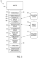
- the modular energy system 2000 can include a housing that is configured to receive and retain the modules 2001, as is shown in FIG. 3 .
- the modular energy system 2000 can also include a variety of different components or accessories that are also connectable to or otherwise associatable with the modules 2001.
- the modular energy system 2000 can be embodied as a generator module 140 ( FIG. 3 ) of a surgical hub 106.
- the modular energy system 2000 can be a distinct system from a surgical hub 106. In such aspects, the modular energy system 2000 can be communicably couplable to a surgical hub 206 for transmitting and/or receiving data therebetween.
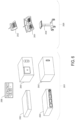
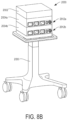
- the modular energy system 2000 can be assembled from a variety of different modules 2001, some examples of which are illustrated in FIG. 6 .
- Each of the different types of modules 2001 can provide different functionality, thereby allowing the modular energy system 2000 to be assembled into different configurations to customize the functions and capabilities of the modular energy system 2000 by customizing the modules 2001 that are included in each modular energy system 2000.
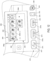
- the modules 2001 of the modular energy system 2000 can include, for example, a header module 2002 (which can include a display screen 2006), an energy module 2004, a technology module 2040, and a visualization module 2042.
- the header module 2002 is configured to serve as the top or uppermost module within the modular energy system stack and can thus lack connectors along its top surface.
- the header module 2002 can also be configured to provide communications, processing, and/or power for the modules 2001 that are connected to the header module 2002.
- the energy module 2004, which can also be referred to as a generator module 140 ( FIG. 3 ), can be configured to generate one or multiple energy modalities for driving electrosurgical and/or ultrasonic surgical instruments connected thereto.
- the technology module 2040 can be configured to provide additional or expanded control algorithms (e.g., electrosurgical or ultrasonic control algorithms for controlling the energy output of the energy module 2004).
- the visualization module 2042 can be configured to interface with visualization devices (i.e., scopes) and accordingly provide increased visualization capabilities.
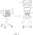
- the modular energy system 2000 can further include a variety of accessories 2029 that are connectable to the modules 2001 for controlling the functions thereof or that are otherwise configured to work on conjunction with the modular energy system 2000.
- the accessories 2029 can include, for example, a single-pedal footswitch 2032, a dual-pedal footswitch 2034, and a cart 2030 for supporting the modular energy system 2000 thereon.
- the footswitches 2032, 2034 can be configured to control the activation or function of particular energy modalities output by the energy module 2004, for example.
- the depicted modular energy system 2000 provides a surgical platform that grows with the availability of technology and is customizable to the needs of the facility and/or surgeons. Further, the modular energy system 2000 supports combo devices (e.g., dual electrosurgical and ultrasonic energy generators) and supports software-driven algorithms for customized tissue effects. Still further, the surgical system architecture reduces the capital footprint by combining multiple technologies critical for surgery into a single system.
- the various modular components utilizable in connection with the modular energy system 2000 can include monopolar energy generators, bipolar energy generators, dual electrosurgical/ultrasonic energy generators, display screens, and various other modules and/or other components, some of which are also described above in connection with FIGS. 1-3 .
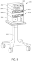
- FIG. 9 illustrates a fourth illustrative configuration of the modular energy system 2000 including a header module 2002 (including a display screen 2006), a first energy module 2004a, a second energy module 2004b, and a technology module 2040 connected together.
- a header module 2002 including a display screen 2006
- a first energy module 2004a including a first energy module 2004a
- a second energy module 2004b including a technology module 2040 connected together.
- the technology module 2040 can be a newly released module that supplements or expands the capabilities of previously released modules (such as the energy module 2004).
- FIG. 13 is a block diagram of a stand-alone hub configuration of a modular energy system 3000, in accordance with at least one aspect of the present disclosure
- FIG. 14 is a block diagram of a hub configuration of a modular energy system 3000 integrated with a surgical control system 3010, in accordance with at least one aspect of the present disclosure.
- the modular energy system 3000 can be either utilized as stand-alone units or integrated with a surgical control system 3010 that controls and/or receives data from one or more surgical hub units.
- the integrated header/Ul module 3002 of the modular energy system 3000 includes a header module and a UI module integrated together as a singular module.
- the header module and the UI module can be provided as separate components that are communicatively coupled though a data bus 3008.
- an example of a stand-alone modular energy system 3000 includes an integrated header module/user interface (UI) module 3002 coupled to an energy module 3004. Power and data are transmitted between the integrated header/Ul module 3002 and the energy module 3004 through a power interface 3006 and a data interface 3008.
- the integrated header/Ul module 3002 can transmit various commands to the energy module 3004 through the data interface 3008. Such commands can be based on user inputs from the UI. As a further example, power may be transmitted to the energy module 3004 through the power interface 3006.
- a surgical hub configuration includes a modular energy system 3000 integrated with a control system 3010 and an interface system 3022 for managing, among other things, data and power transmission to and/or from the modular energy system 3000.
- the modular energy system depicted in FIG. 14 includes an integrated header module/Ul module 3002, a first energy module 3004, and a second energy module 3012.
- a data transmission pathway is established between the system control unit 3024 of the control system 3010 and the second energy module 3012 through the first energy module 3004 and the header/UI module 3002 through a data interface 3008.
- a power pathway extends between the integrated header/Ul module 3002 and the second energy module 3012 through the first energy module 3004 through a power interface 3006.
- the first energy module 3004 is configured to function as a power and data interface between the second energy module 3012 and the integrated header/Ul module 3002 through the power interface 3006 and the data interface 3008.
- This arrangement allows the modular energy system 3000 to expand by seamlessly connecting additional energy modules to energy modules 3004, 3012 that are already connected to the integrated header/Ul module 3002 without the need for dedicated power and energy interfaces within the integrated header/Ul module 3002.
- the system control unit 3024 which may be referred to herein as a control circuit, control logic, microprocessor, microcontroller, logic, or FPGA, or various combinations thereof, is coupled to the system interface 3022 via energy interface 3026 and instrument communication interface 3028.
- the system interface 3022 is coupled to the first energy module 3004 via a first energy interface 3014 and a first instrument communication interface 3016.
- the system interface 3022 is coupled to the second energy module 3012 via a second energy interface 3018 and a second instrument communication interface 3020.
- additional modules such as additional energy modules, are stacked in the modular energy system 3000, additional energy and communications interfaces are provided between the system interface 3022 and the additional modules.
- the energy modules 3004, 3012 are connectable to a hub and can be configured to generate electrosurgical energy (e.g., bipolar or monopolar), ultrasonic energy, or a combination thereof (referred to herein as an "advanced energy” module) for a variety of energy surgical instruments.
- electrosurgical energy e.g., bipolar or monopolar
- ultrasonic energy e.g., bipolar or monopolar
- ultrasonic energy e.g., bipolar or monopolar
- ultrasonic controller e.g., an ultrasonic controller, an advanced energy RF controller, bipolar RF controller, and control algorithms executed by the controller that receives outputs from the controller and controls the operation of the various energy modules 3004, 3012 accordingly.
- the controllers described herein may be implemented as a control circuit, control logic, microprocessor, microcontroller, logic, or FPGA, or various combinations thereof.
- FIGS. 15-17 are block diagrams of various modular energy systems connected together to form a hub, in accordance with at least one aspect of the present disclosure.
- FIGS. 15-17 depict various diagrams (e.g., circuit or control diagrams) of hub modules.
- the modular energy system 3000 includes multiple energy modules 3004 ( FIG. 16 ), 3012 ( FIG. 17 ), a header module 3150 ( FIG. 17 ), a UI module 3030 ( FIG. 15 ), and a communications module 3032 ( FIG. 15 ), in accordance with at least one aspect of the present disclosure.
- the UI module 3030 includes a touch screen 3046 displaying various relevant information and various user controls for controlling one or more parameters of the modular energy system 3000.
- the UI module 3030 is attached to the top header module 3150, but is separately housed so that it can be manipulated independently of the header module 3150. For example, the UI module 3030 can be picked up by a user and/or reattached to the header module 3150. Additionally, or alternatively, the UI module 3030 can be slightly moved relative to the header module 3150 to adjust its position and/or orientation. For example, the UI module 3030 can be tilted and/or rotated relative to the header module 3150.
- the various hub modules can include light piping around the physical ports to communicate instrument status and also connect on-screen elements to corresponding instruments.
- Light piping is one example of an illumination technique that may be employed to alert a user to a status of a surgical instrument attached/connected to a physical port.
- illuminating a physical port with a particular light directs a user to connect a surgical instrument to the physical port.
- illuminating a physical port with a particular light alerts a user to an error related an existing connection with a surgical instrument.
- FIG. 15 there is shown a block diagram of a user interface (UI) module 3030 coupled to a communications module 3032 via a pass-through hub connector 3034, in accordance with at least one aspect of the present disclosure.
- the UI module 3030 is provided as a separate component from a header module 3150 (shown in FIG. 17 ) and may be communicatively coupled to the header module 3150 via a communications module 3032, for example.
- the UI module 3030 can include a UI processor 3040 that is configured to represent declarative visualizations and behaviors received from other connected modules, as well as perform other centralized UI functionality, such as system configuration (e.g., language selection, module associations, etc.).
- the UI processor 3040 can be, for example, a processor or system on module (SOM) running a framework such as Qt, .NET WPF, Web server, or similar.
- SOM system on module
- the UI module 3030 includes a touchscreen 3046, a liquid crystal display 3048 (LCD), and audio output 3052 (e.g., speaker, buzzer).
- the UI processor 3040 is configured to receive touchscreen inputs from a touch controller 3044 coupled between the touch screen 3046 and the UI processor 3040.
- the UI processor 3040 is configured to output visual information to the LCD display 3048 and to output audio information the audio output 3052 via an audio amplifier 3050.
- the UI processor 3040 is configured to interface to the communications module 3032 via a switch 3042 coupled to the pass-through hub connector 3034 to receive, process, and forward data from the source device to the destination device and control data communication therebetween.
- DC power is supplied to the UI module 3030 via DC/DC converter modules 3054.
- the DC power is passed through the pass-through hub connector 3034 to the communications module 3032 through the power bus 3006.
- Data is passed through the pass-through hub connector 3034 to the communications module 3032 through the data bus 3008.
- Switches 3042, 3056 receive, process, and forward data from the source device to the destination device.
- the communications module 3032 can include a gateway 3058 that is configured to shuttle select traffic (i.e., data) between two disparate networks (e.g., an internal network and/or a hospital network) that are running different protocols.
- the communications module 3032 includes a first pass-through hub connector 3036 to couple the communications module 3032 to other modules.
- the communications module 3032 is coupled to the UI module 3030.
- the communications module 3032 is configured to couple to other modules (e.g., energy modules) via a second pass-through hub connector 3038 to couple the communications module 3032 to other modules via a switch 3056 disposed between the first and second pass-through hub connectors 3036, 3038 to receive, process, and forward data from the source device to the destination device and control data communication therebetween.
- the switch 3056 also is coupled to a gateway 3058 to communicate information between external communications ports and the UI module 3030 and other connected modules.
- the gateway 3058 may be coupled to various communications modules such as, for example, an Ethernet module 3060 to communicate to a hospital or other local network, a universal serial bus (USB) module 3062, a WiFi module 3064, and a Bluetooth module 3066, among others.
- the communications modules may be physical boards located within the communications module 3032 or may be a port to couple to remote communications boards.
- all of the modules are controlled by a single UI module 3030 that is disposed on or integral to a header module.
- FIG. 17 shows a stand alone header module 3150 to which the UI module 3030 can be attached.
- FIGS. 13 , 14 , and 18 show an integrated header/Ul Module 3002.
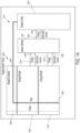
- FIG. 16 there is shown a block diagram of an energy module 3004, in accordance with at least one aspect of the present disclosure.
- the communications module 3032 ( FIG. 15 ) is coupled to the energy module 3004 via the second pass-through hub connector 3038 of the communications module 3032 and a first pass-through hub connector 3074 of the energy module 3004.
- the energy module 3004 may be coupled to other modules, such as a second energy module 3012 shown in FIG. 17 , via a second pass-through hub connector 3078.
- a switch 3076 disposed between the first and second pass-through hub connectors 3074, 3078 receives, processes, and forwards data from the source device to the destination device and controls data communication therebetween. Data is received and transmitted through the data bus 3008.
- the energy module 3032 includes a controller 3082 to control various communications and processing functions of the energy module 3004.
- DC power is received and transmitted by the energy module 3004 through the power bus 3006.
- the power bus 3006 is coupled to DC/DC converter modules 3138 to supply power to adjustable regulators 3084, 3107 and isolated DC/DC converter ports 3096, 3112, 3132.
- the energy module 3004 can include an ultrasonic wideband amplifier 3086, which in one aspect may be a linear class H amplifier that is capable of generating arbitrary waveforms and drive harmonic transducers at low total harmonic distortion (THD) levels.
- the ultrasonic wideband amplifier 3086 is fed by a buck adjustable regulator 3084 to maximize efficiency and controlled by the controller 3082, which may be implemented as a digital signal processor (DSP) via a direct digital synthesizer (DDS), for example.
- DDS digital signal processor
- DDS direct digital synthesizer
- the DDS can either be embedded in the DSP or implemented in the field-programmable gate array (FPGA), for example.
- the controller 3082 controls the ultrasonic wideband amplifier 3086 via a digital-to-analog converter 3106 (DAC).
- DAC digital-to-analog converter
- the output of the ultrasonic wideband amplifier 3086 is fed to an ultrasonic power transformer 3088, which is coupled to an ultrasonic energy output portion of an advanced energy receptacle 3100.
- Ultrasonic voltage (V) and current (I) feedback (FB) signals which may be employed to compute ultrasonic impedance, are fed back to the controller 3082 via an ultrasonic VI FB transformer 3092 through an input portion of the advanced energy receptacle 3100.
- the ultrasonic voltage and current feedback signals are routed back to the controller 3082 through an analog-to-digital converter 3102 (A/D).
- A/D analog-to-digital converter
- Also coupled to the controller 3082 through the advanced energy receptacle 3100 is the isolated DC/DC converter port 3096, which receives DC power from the power bus 3006, and a medium bandwidth data port 3098.
- the energy module 3004 can include a wideband RF power amplifier 3108, which in one aspect may be a linear class H amplifier that is capable of generating arbitrary waveforms and drive RF loads at a range of output frequencies.
- the wideband RF power amplifier 3108 is fed by an adjustable buck regulator 3107 to maximize efficiency and controlled by the controller 3082, which may be implemented as DSP via a DDS.
- the DDS can either be embedded in the DSP or implemented in the FPGA, for example.
- the controller 3082 controls the wideband RF amplifier 3086 via a DAC 3122.
- the output of the wideband RF power amplifier 3108 can be fed through RF selection relays 3124.
- the RF selection relays 3124 are configured to receive and selectively transmit the output signal of the wideband RF power amplifier 3108 to various other components of the energy module 3004.
- the output signal of the wideband RF power amplifier 3108 can be fed through RF selection relays 3124 to an RF power transformer 3110, which is coupled to an RF output portion of a bipolar RF energy receptacle 3118.
- Bipolar RF voltage (V) and current (I) feedback (FB) signals which may be employed to compute RF impedance, are fed back to the controller 3082 via an RF VI FB transformer 3114 through an input portion of the bipolar RF energy receptacle 3118.
- the RF voltage and current feedback signals are routed back to the controller 3082 through an A/D 3120. Also coupled to the controller 3082 through the bipolar RF energy receptacle 3118 is the isolated DC/DC converter port 3112, which receives DC power from the power bus 3006, and a low bandwidth data port 3116.
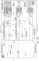
- FIG. 17 is a block diagram of a second energy module 3012 coupled to a header module 3150, in accordance with at least one aspect of the present disclosure.
- the first energy module 3004 shown in FIG. 16 is coupled to the second energy module 3012 shown in FIG. 17 by coupling the second pass-through hub connector 3078 of the first energy module 3004 to a first pass-through hub connector 3074 of the second energy module 3012.
- the second energy module 3012 can a similar energy module to the first energy module 3004, as is illustrated in FIG. 17 .
- the second energy module 2012 can be a different energy module compared to the first energy module, such as an energy module illustrated in FIG. 19 , described in more detail.
- the addition of the second energy module 3012 to the first energy module 3004 adds functionality to the modular energy system 3000.
- the header audio/screen module 3178 includes a touchscreen 3220 coupled to a touch controller 3218.
- the touch controller 3218 is coupled to the header/Ul controller 3170 to read inputs from the touchscreen 3220.
- the header/Ul controller 3170 drives an LCD display 3224 through a display/port video output signal 3222.
- the header/UI controller 3170 is coupled to an audio amplifier 3226 to drive one or more speakers 3228.
- the header/UI module 3002 provides a touchscreen 3220 user interface configured to control modules connected to one control or header module 3002 in a modular energy system 3000.
- the touchscreen 3220 can be used to maintain a single point of access for the user to adjust all modules connected within the modular energy system 3000.
- Additional hardware modules e.g., a smoke evacuation module
- the user touchscreen 3220 can provide access to the settings of modules attached to the modular energy system 3000.
- the user interface LCD display 3224 arrangement can be configured to change according to the number and types of modules that are connected to the header/UI module 3002. For example, a first user interface can be displayed on the LCD display 3224 for a first application where one energy module and one smoke evacuation module are connected to the header/UI module 3002, and a second user interface can be displayed on the LCD display 3224 for a second application where two energy modules are connected to the header/UI module 3002. Further, the user interface can alter its display on the LCD display 3224 as modules are connected and disconnected from the modular energy system 3000.
- the header/UI module 3002 provides a user interface LCD display 3224 configured to display on the LCD display coloring corresponds to the port lighting.
- the coloring of the instrument panel and the LED light around its corresponding port will be the same or otherwise correspond with each other. Each color can, for example, convey a unique meaning. This way, the user will be able to quickly assess which instrument the indication is referring to and the nature of the indication. Further, indications regarding an instrument can be represented by the changing of color of the LED light lined around its corresponding port and the coloring of its module. Still further, the message on screen and hardware/software port alignment can also serve to convey that an action must be taken on the hardware, not on the interface. In various aspects, all other instruments can be used while alerts are occurring on other instruments. This allows the user to be able to quickly assess which instrument the indication is referring to and the nature of the indication.
- the header/UI module 3002 provides a user interface screen configured to display on the LCD display 3224 to present procedure options to a user.
- the user interface can be configured to present the user with a series of options (which can be arranged, e.g., from broad to specific). After each selection is made, the modular energy system 3000 presents the next level until all selections are complete.
- These settings could be managed locally and transferred via a secondary means (such as a USB thumb drive). Alternatively, the settings could be managed via a portal and automatically distributed to all connected systems in the hospital.
- the procedure options can include, for example, a list of factory preset options categorized by specialty, procedure, and type of procedure.
- the header module can be configured to set any connected instruments to factory-preset settings for that specific procedure.
- the procedure options can also include, for example, a list of surgeons, then subsequently, the specialty, procedure, and type. Once a user completes a selection, the system may suggest the surgeon's preferred instruments and set those instrument's settings according to the surgeon's preference (i.e., a profile associated with each surgeon storing the surgeon's preferences).
- the header/UI module 3002 provides a user interface screen configured to display on the LCD display 3224 critical instrument settings.
- each instrument panel displayed on the LCD display 3224 of the user interface corresponds, in placement and content, to the instruments plugged into the modular energy system 3000. When a user taps on a panel, it can expand to reveal additional settings and options for that specific instrument and the rest of the screen can, for example, darken or otherwise be de-emphasized.
- the header/UI module 3002 provides an instrument settings panel of the user interface configured to comprise/display controls that are unique to an instrument and allow the user to increase or decrease the intensity of its output, toggle certain functions, pair it with system accessories like a footswitch connected to header footswitch module 3186, access advanced instrument settings, and find additional information about the instrument.
- the user can tap/select an "Advanced Settings" control to expand the advanced settings drawer displayed on the user interface LCD display 3224.
- the user can then tap/select an icon at the top right-hand corner of the instrument settings panel or tap anywhere outside of the panel and the panel will scale back down to its original state.
- the user interface is configured to display on the LCD display 3224 only the most critical instrument settings, such as power level and power mode, on the ready/home screen for each instrument panel. This is to maximize the size and readability of the system from a distance.
- the panels and the settings within can be scaled proportionally to the number of instruments connected to the system to further improve readability. As more instruments are connected, the panels scale to accommodate a greater amount of information.
- the header network module 3180 includes a plurality of network interfaces 3264, 3266, 3268 (e.g., Ethernet) to network the header/UI module 3002 to other modules of the modular energy system 3000.
- one network interface 3264 may be a 3rd party network interface
- another network interface 3266 may be a hospital network interface
- yet another network interface 3268 may be located on the backplane network interface connector 3182.
- the header standby processor module 3184 includes a standby processor 3204 coupled to an On/Off switch 3210.
- the standby processor 3204 conducts an electrical continuity test by checking to see if electrical current flows in a continuity loop 3206.
- the continuity test is performed by placing a small voltage across the continuity loop 3206.
- a serial bus 3208 couples the standby processor 3204 to the backplane connector 3182.
- the header footswitch module 3186 includes a controller 3240 coupled to a plurality of analog footswitch ports 3254, 3256, 3258 through a plurality of corresponding presence/ID and switch state modules 3242, 3244, 3246, respectively.
- the controller 3240 also is coupled to an accessory port 3260 via a presence/ID and switch state module 3248 and a transceiver module 3250.
- the accessory port 3260 is powered by an accessory power module 3252.
- the controller 3240 is coupled to header/Ul controller 3170 via an isolated communication module 3234 and first and second safety critical control modules 3230, 3232.
- the header footswitch module 3186 also includes DC/DC converter modules 3238.
- the header/UI module 3002 provides a user interface screen configured to display on the LCD display 3224 for controlling a footswitch connected to any one of the analog footswitch ports 3254, 3256, 3258.
- the instrument panel appears with a warning icon next to the footswitch icon.
- the instrument settings can be, for example, greyed out, as the instrument cannot be activated without a footswitch.
- the system is configured to automatically assign footswitches to non hand-activated instruments using logic, which can further assign single or double-pedal footswitches to the appropriate instrument. If the user wants to assign/reassign footswitches manually there are two flows that can be utilized.
- the header/UI module 3002 provides a global footswitch button. Once the user taps on the global footswitch icon (located in the upper right of the user interface LCD display 3224), the footswitch assignment overlay appears and the contents in the instrument modules dim. A (e.g., photo-realistic) representation of each attached footswitch (dual or single-pedal) appears on the bottom if unassigned to an instrument or on the corresponding instrument panel. Accordingly, the user can drag and drop these illustrations into, and out of, the boxed icons in the footswitch assignment overlay to assign, unassign, and reassign footswitches to their respective instruments.
- A e.g., photo-realistic representation of each attached footswitch (dual or single-pedal) appears on the bottom if unassigned to an instrument or on the corresponding instrument panel. Accordingly, the user can drag and drop these illustrations into, and out of, the boxed icons in the footswitch assignment overlay to assign, unassign,
- the header/UI module 3002 provides a user interface screen displayed on the LCD display 3224 indicating footswitch auto-assignment, in accordance with at least one aspect of the present disclosure.
- the modular energy system 3000 can be configured to auto-assign a footswitch to an instrument that does not have hand activation.
- the header/UI module 3002 can be configured to correlate the colors displayed on the user interface LCD display 3224 to the lights on the modules themselves as means of tracking physical ports with user interface elements.
- the header/UI module 3002 may be configured to depict various applications of the user interface with differing number of modules connected to the modular energy system 3000.
- the overall layout or proportion of the user interface elements displayed on the LCD display 3224 can be based on the number and type of instruments plugged into the header/Ul module 3002. These scalable graphics can provide the means to utilize more of the screen for better visualization.
- the header/UI module 3002 may be configured to depict a user interface screen on the LCD display 3224 to indicate which ports of the modules connected to the modular energy system 3000 are active.
- the header/UI module 3002 can be configured to illustrate active versus inactive ports by highlighting active ports and dimming inactive ports.
- ports can be represented with color when active (e.g., monopolar tissue cut with yellow, monopolar tissue coagulation with blue, bipolar tissue cut with blue, advanced energy tissue cut with warm white, and so on). Further, the displayed color will match the color of the light piping around the ports. The coloring can further indicate that the user cannot change settings of other instruments while an instrument is active.
- the header/UI module 3002 can be configured to depict the bipolar, monopolar, and ultrasonic ports of a first energy module as active and the monopolar ports of a second energy module as likewise active.
- the header/UI module 3002 can be configured to depict a user interface screen on the LCD display 3224 to display a global settings menu. In one aspect, the header/UI module 3002 can be configured to display a menu on the LCD display 3224 to control global settings across any modules connected to the modular energy system 3000.
- the global settings menu can be, for example, always displayed in a consistent location (e.g., always available in upper right hand corner of main screen).
- the header/UI module 3002 can be configured to depict a user interface screen on the LCD display 3224 configured to prevent changing of settings while a surgical instrument is in use.
- the header/UI module 3002 can be configured to prevent settings from being changed via a displayed menu when a connected instrument is active.
- the user interface screen can include, for example, an area (e.g., the upper left hand corner) that is reserved for indicating instrument activation while a settings menu is open.
- a user has opened the bipolar settings while monopolar coagulation is active.
- the settings menu could then be used once the activation is complete.
- the header/UI module 3002 can be is configured to never overlay any menus or other information over the dedicated area for indicating critical instrument information in order to maintain display of critical information.
- the header/UI module 3002 can be configured to depict a user interface screen on the LCD display 3224 configured to display instrument errors.
- instrument error warnings may be displayed on the instrument panel itself, allowing user to continue to use other instruments while a nurse troubleshoots the error. This allows users to continue the surgery without the need to stop the surgery to debug the instrument.
- the header/UI module 3002 can be configured to depict a user interface screen on the LCD display 3224 to display different modes or settings available for various instruments.
- the header/UI module 3002 can be configured to display settings menus that are appropriate for the type or application of surgical instrument(s) connected to the stack/hub. Each settings menu can provide options for different power levels, energy delivery profiles, and so on that are appropriate for the particular instrument type.
- the header/UI module 3002 can be configured to display different modes available for bipolar, monopolar cut, and monopolar coagulation applications.
- the header/UI module 3002 can be configured to depict a user interface screen on the LCD display 3224 to display pre-selected settings. In one aspect, the header/UI module 3002 can be configured to receive selections for the instrument/device settings before plugging in instruments so that the modular energy system 3000 is ready before the patient enters the operating room. In one aspect, the user can simply click a port and then change the settings for that port. In the depicted aspect, the selected port appears as faded to indicate settings are set, but no instrument is plugged into that port.
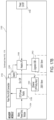
- FIG. 19 is a block diagram of an energy module 3270 for a hub, such as the energy module depicted in FIGS. 13 , 14 , 16 , and 17 , in accordance with at least one aspect of the present disclosure.
- the energy module 3270 is configured to couple to a header module, header/Ul module, and other energy modules via the first and second pass-through hub connectors 3272, 3276.
- a switch 3076 disposed between the first and second pass-through hub connectors 3272, 3276 receives, processes, and forwards data from the source device to the destination device and controls data communication therebetween. Data is received and transmitted through the data bus 3008.
- the energy module 3270 includes a controller 3082 to control various communications and processing functions of the energy module 3270.
- the power bus 3006 is coupled to the DC/DC converter modules 3138 to supply power to adjustable regulators 3084, 3107 and isolated DC/DC converter ports 3096, 3112, 3132.
- the energy module 3270 can include an ultrasonic wideband amplifier 3086, which in one aspect may be a linear class H amplifier that is capable of generating arbitrary waveforms and drive harmonic transducers at low total harmonic distortion (THD) levels.
- the ultrasonic wideband amplifier 3086 is fed by a buck adjustable regulator 3084 to maximize efficiency and controlled by the controller 3082, which may be implemented as a digital signal processor (DSP) via a direct digital synthesizer (DDS), for example.
- DDS digital signal processor
- DDS direct digital synthesizer
- the DDS can either be embedded in the DSP or implemented in the field-programmable gate array (FPGA), for example.
- the controller 3082 controls the ultrasonic wideband amplifier 3086 via a digital-to-analog converter 3106 (DAC).
- DAC digital-to-analog converter
- the output of the ultrasonic wideband amplifier 3086 is fed to an ultrasonic power transformer 3088, which is coupled to an ultrasonic energy output portion of the advanced energy receptacle 3100.
- Ultrasonic voltage (V) and current (I) feedback (FB) signals which may be employed to compute ultrasonic impedance, are fed back to the controller 3082 via an ultrasonic VI FB transformer 3092 through an input portion of the advanced energy receptacle 3100.
- the ultrasonic voltage and current feedback signals are routed back to the controller 3082 through an analog multiplexer 3280 and a dual analog-to-digital converter 3278 (A/D).
- the dual A/D 3278 has a sampling rate of 80 MSPS.
- the isolated DC/DC converter port 3096 which receives DC power from the power bus 3006, and a medium bandwidth data port 3098.
- the controller 3082 is configured to switch the adjustable buck regulator 3107 between the plurality of states. In a first state, the controller drives the adjustable buck regulator 3107 to output an RF energy signal to the first wideband RF power amplifier 3108. In a second state, the controller drives the adjustable buck regulator 3107 to output an RF energy signal to the second wideband RF power amplifier 3286. In a third state, the controller drives the adjustable buck regulator 3107 to output an RF energy signal to the third wideband RF power amplifier 3288.
- the output of the first wideband RF power amplifier 3108 can be fed to an RF power transformer 3090, which is coupled to an RF output portion of an advanced energy receptacle 3100.
- RF voltage (V) and current (I) feedback (FB) signals which may be employed to compute RF impedance, are fed back to the controller 3082 via RF VI FB transformers 3094 through an input portion of the advanced energy receptacle 3100.
- the RF voltage and current feedback signals are routed back to the controller 3082 through the RF VI FB transformers 3094, which are coupled to an analog multiplexer 3284 and a dual A/D 3282 coupled to the controller 3082.
- the dual A/D 3282 has a sampling rate of 80 MSPS.
- the output of the second RF wideband power amplifier 3286 is fed through an RF power transformer 3128 of the RF monopolar receptacle 3136.
- Monopolar RF voltage (V) and current (I) feedback (FB) signals which may be employed to compute RF impedance, are fed back to the controller 3082 via RF VI FB transformers 3130 through an input portion of the monopolar RF energy receptacle 3136.
- the RF voltage and current feedback signals are routed back to the controller 3082 through the analog multiplexer 3284 and the dual A/D 3282.
- Also coupled to the controller 3082 through the monopolar RF energy receptacle 3136 is the isolated DC/DC converter port 3132, which receives DC power from the power bus 3006, and a low bandwidth data port 3134.
- the output of the third RF wideband power amplifier 3288 is fed through an RF power transformer 3110 of a bipolar RF receptacle 3118.
- Bipolar RF voltage (V) and current (I) feedback (FB) signals which may be employed to compute RF impedance, are fed back to the controller 3082 via RF VI FB transformers 3114 through an input portion of the bipolar RF energy receptacle 3118.
- the RF voltage and current feedback signals are routed back to the controller 3082 through the analog multiplexer 3280 and the dual A/D 3278.
- Also coupled to the controller 3082 through the bipolar RF energy receptacle 3118 is the isolated DC/DC converter port 3112, which receives DC power from the power bus 3006, and a low bandwidth data port 3116.
- a contact monitor 3290 is coupled to an NE receptacle 3292. Power is fed to the NE receptacle 3292 from the monopolar receptacle 3136.
- the modular energy system 3000 can be configured to detect instrument presence in a receptacle 3100, 3118, 3136 via a photointerrupter, magnetic sensor, or other non-contact sensor integrated into the receptacle 3100, 3118, 3136.
- This approach prevents the necessity of allocating a dedicated presence pin on the MTD connector to a single purpose and instead allows multi-purpose functionality for MTD signal pins 6-9 while continuously monitoring instrument presence.
- the modules of the modular energy system 3000 can include an optical link allowing high speed communication (10 - 50Mb/s) across the patient isolation boundary. This link would carry device communications, mitigation signals (watchdog, etc.), and low bandwidth run-time data. In some aspects, the optical link(s) will not contain real-time sampled data, which can be done on the non-isolated side.
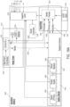
- the modular energy system 6000 comprises a header module 6002 and an "N" number of surgical modules 6004, where "N" is an integer greater than or equal to one.
- the modular energy system 6000 includes a UI module such as, for example, the UI module 3030 and/or a communication module such as, for example, the communication module 3032.
- pass-through hub connectors couple individual modules to one another in a stack configuration.
- the header module 6002 is coupled to a surgical module 6004 via pass-through hub connectors 6005, 6006.
- the modular energy system 6000 comprises an example power architecture that consists of a single AC/DC power supply 6003 that provides power to all the surgical modules in the stack.
- the AC/DC power supply 6003 is housed in the header module 6002, and utilizes a power backplane 6008 to distribute power to each module in the stack.
- the example of FIG. 20 demonstrates three separate power domains on the power backplane 6008: a primary power domain 6009, a standby power domain 6010, and an Ethernet switch power domain 6013.
- the primary power domain 6009 is controlled by the header module 6002.
- a local power switch 6018 is positioned on the header module 6002.
- a remote on/off interface 6016 can be configured to control a system power control 6017 on the header module 6002, for example.
- the remote on/off interface 6016 is configured to transmit pulsed discrete commands (separate commands for On and Off) and a power status telemetry signal.
- the primary power domain 6009 is configured to distribute power to all the modules in the stack configuration following a user-initiated power-up.
- the modules of the modular energy system 6000 can be communicably coupled to the header module 6002 and/or to each other via a communication (Serial bus/Ethernet) interface 6040 such that data or other information is shared by and between the modules of which the modular energy system is constructed.
- An Ethernet switch domain 6013 can be derived from the primary power domain 6009, for example.
- the Ethernet switch power domain 6013 is segregated into a separate power domain, which is configured to power Ethernet switches within each of the modules in the stack configuration, so that the primary communications interface 6040 will remain alive when local power to a module is removed.
- the modular energy system 6000 includes secondary, low speed, communication interface between modules for critical, power related functions including module power sequencing and module power status.
- the secondary communications interface can, for example, be a multi-drop Local Interconnect Network (LIN), where the header module is the master and all downstream modules are slaves.
- LIN Local Interconnect Network
- a standby power domain 6010 is a separate output from the AC/DC power supply 6003 that is always live when the supply is connected to mains power 6020.
- the standby power domain 6010 is used by all the modules in the system to power circuitry for a mitigated communications interface, and to control the local power to each module. Further, the standby power domain 6010 is configured to provide power to circuitry that is critical in a standby mode such as, for example, on/off command detection, status LEDs, secondary communication bus, etc.
- the individual surgical modules 6004 lack independent power supplies and, as such, rely on the header module 6002 to supply power in the stack configuration. Only the header module 6002 is directly connected to the mains power 6020. The surgical modules 6004 lack direct connections to the mains power 6020, and can receive power only in the stack configuration. This arrangement improves the safety of the individual surgical modules 6004, and reduces the overall footprint of the modular energy system 6000. This arrangement further reduces the number of cords required for proper operation of the modular energy system 6000, which can reduce clutter and footprint in the operating room.
- a surgical instrument connected to surgical modules 6004 of a modular energy system 6000 receives therapeutic energy for tissue treatment that is generated by the surgical module 6004 from power delivered to the surgical module 6004 from the AC/DC power supply 6003 of the header module 6002.
- the energy generated by the AC/DC power supply 6003 of the header module 6002 is transmitted through a segmented power backplane 6008 defined through the modular energy system 6000.
- the header module 6002 houses a power backplane segment 6008'
- the first surgical module 6004' houses a power backplane segment 6008
- the second surgical module 6004" houses a power backplane segment 6008"'.
- the power backplane segment 6008' is detachably coupled to the power backplane segment 6008" in the stack configuration.
- the power backplane 6008" is detachably coupled to the power backplane segment 6008′′′ in the stack configuration. Accordingly, energy flows from the AC/DC power supply 6003 to the power backplane segment 6008', then to the power backplane segment 6008", and then to the power backplane segment 6008′′′.
- the power backplane segment 6008' is detachably connected to the power backplane segment 6008" via pass-through hub connectors 6005, 6006 in the stack configuration. Further, the power backplane segment 6008" is detachably connected to the power backplane segment 6008′′′ via pass-through hub connectors 6025, 6056 in the stack configuration.
- removing a surgical module from the stack configuration severs its connection to the power supply 6003. For example, separating the second surgical module 6004" from the first surgical module 6004' disconnects the power backplane segment 6008′′′ from the power backplane segment 6008".
- connection between the power backplane segment 6008" and the power backplane segment 6008′′′ remains intact as long as the header module 6002 and the first surgical module 6004' remain in the stack configuration. Accordingly, energy can still flow to the first surgical module 6004' after disconnecting the second surgical module 6004" through the connection between the header module 6002 and the first surgical module 6004'. Separating connected modules can be achieved, in certain instances, by simply pulling the surgical modules 6004 apart.
- each of the modules 6002, 6004 includes a mitigated module control 6023.
- the mitigated module controls 6023 are coupled to corresponding local power regulation modules 6024 that are configured to regulate power based on input from the mitigated module controls 6023.
- the mitigated module controls 6023 allow the header module 6002 to independently control the local power regulation modules 6024.
- the communication backplane segment 6027' is detachably coupled to the communication backplane segment 6027" in the stack configuration via the pass-through hub connectors 6005, 6006. Further, the communication backplane 6027" is detachably coupled to the communication backplane segment 6027" in the stack configuration via the pass-through hub connectors 6025, 6026.
- the example of FIG. 20 depicts a modular energy system 6000 includes a header module 6002 and two surgical modules 6004' 6004", this is not limiting. Modular energy systems with more or less surgical modules are contemplated by the present disclosure.
- the modular energy system 6000 includes other modules such as, for example, the communications module 3032 ( FIG. 15 ).
- the header module 6502 supports a display screen such as, for example, the display 2006 ( FIG. 7A ) that renders a GUI such as, for example, the GUI 2008 for relaying information regarding the modules connected to the header module 6002.
- the GUI 2008 of the display screen 2006 can provide a consolidated point of control all of the modules making up the particular configuration of a modular energy system.
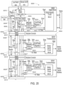
- FIG. 21 depicts a simplified schematic diagram of the modular energy system 6000, which illustrates a primary communications interface 6040 between the header module 6002 and the surgical modules 6004.
- the primary communications interface 6040 communicably connects module processors 6041, 6041', 6041" of the header module 6002 and the surgical modules 6004. Commands generated by the module processor 6041 of the header module are transmitted downstream to a desired functional surgical module via the primary communications interface 6040.
- the primary communications interface 6040 is configured to establish a two-way communication pathway between neighboring modules. In other instances, the primary communications interface 6040 is configured to establish a one-way communication pathway between neighboring modules.
- the primary communications interface 6040 includes a segmented communication backplane 6031, which is similar in many respects to the segmented power backplane 6008. Communication between the header module 6002 and the surgical modules 6004 can be achieved through the segmented communication backplane 6031 defined through the modular energy system 6000.
- the header module 6002 houses a communication backplane segment 6031'
- the first surgical module 6004' houses a communication backplane segment 6031
- the second surgical module 6004" houses a communication backplane segment 6031′′′.
- the communication backplane segment 6031' is detachably coupled to the communication backplane segment 6031" in the stack configuration via the pass-through hub connectors 6005, 6006.
- the communication backplane 6031" is detachably coupled to the communication backplane segment 6031" in the stack configuration via the pass-through hub connectors 6025, 6026.
- the primary communications interface 6040 is implemented using the DDS framework running on a Gigabit Ethernet interface.
- the module processors 6041, 6041', 6041" are connected to Gigabit Ethernet Phy 6044, and Gigabit Ethernet Switches 6042', 6042".
- the segmented communication backplane 6031 connects the Gigabit Ethernet Phy 6044 and the Gigabit Ethernet Switches 6042 of the neighboring modules.
- the header module 6002 includes a separate Gigabit Ethernet Phy 6045 for an external communications interface 6043 with the processor module 6041 of the header module 6002.
- the processor module 6041 of the header module 6002 handles firewalls and information routing.
- the AC/DC power supply 6003 may provide an AC Status signal 6011 that indicates a loss of AC power supplied by the AC/DC power supply 6003.
- the AC status signal 6011 can be provided to all the modules of the modular energy system 6000 via the segmented power backplane 6008 to allow each module as much time as possible for a graceful shutdown, before primary output power is lost.
- the AC status signal 6011 is received by the module specific circuits 6013, 6014, 6015, for example.
- the system power control 6017 can be configured to detect AC power loss. In at least one example, the AC power loss is detected via one or more suitable sensors.
- the primary power input to all modules can be fused or a similar method of current limiting can be used (e-fuse, circuit breaker, etc.).
- Ethernet switch power is segregated into a separate power domain 6013 so that the primary communications interface 6040 remains alive when local power to a module is removed. In other words, primary power can be removed and/or diverted from a surgical module without losing its ability to communicate with other surgical modules 6004 and/or the header module 6002.
- the disclosure now turns to describe various aspects of other modular energy systems.
- the other modular energy systems are substantially similar to the modular energy system 2000, the modular energy system 3000, and/or the modular energy system 6000.
- various details of the other modular energy systems being described in the following sections, which are similar to the modular energy system 2000, the modular energy system 3000, and/or the modular energy system 6000, are not repeated herein. Any aspect of the other modular energy systems described below can be brought into the modular energy system 2000, the modular energy system 3000, or the modular energy system 6000.
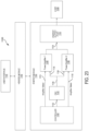
- the controller 1082 is electrically connected to a first switch 1012, which can be actuated and de-actuated by a first switch select signal 1016 controlled by the controller 1082.
- the first switch 1012 is disposed between the controller 1082 and the first power amplifier circuit 1006.
- the first switch 1012 couples the output of a digital-to-analog converter 1022 (DAC) to the analog input of the first power amplifier circuit 1006 when the first switch 1012 is activated ON as controlled by the first switch select signal 1016.
- DAC digital-to-analog converter
- the first switch 1012 may be implemented as a RF selection relay controlled by the first switch select signal 1016 provided by the controller 1082.
- the second switch 1014 also may be implemented as a RF selection relay controlled by the second switch select signal 1018 provided by the controller 1082. It should be noted that when the first switch 1012 is ON, the second switch 1014 is OFF such when the analog signal at the analog output 1034 of the DAC 1022 is coupled to the input 1036 of the first power amplifier circuit 1006, the input 1038 of the second power amplifier circuit 1008 is open.
- both switches 1012, 1014 can be in the OFF state at the same time, but both switches 1012, 1014, cannot be in the ON state at the same time. It is contemplated, however, that in other aspects of the present disclosure, the circuitry may be adapted and configured to enable power blending between the first and second power amplifier circuits 1006, 1008.
- the controller 1082 of the energy module 1004 may be implemented as a microcontroller, computer, digital timing circuit, or a digital signal processor (DSP) via a direct digital synthesizer (DDS), for example.
- DDS can either be embedded in the DSP or implemented in a field-programmable gate array (FPGA), for example.
- the controller 1082 is configured to apply a digital waveform to the digital input 1032 of the DAC 1002 and the analog signal at the analog output 1034 of the DAC 1022 to the input of either the first or second power amplifier circuits 1006, 1008 as may be selected by the controller 1082.
- the controller 1082 is further configured to determine the waveshape in digital form, input impedance (Z), current (I), power (P), voltage (V), and frequency (f) of the desired output signal 1024 of the energy module 1004 to be applied to the load 1040.
- the DAC 1022 converts the digital signal waveform segments to an analog signal that is amplified by the first or second power amplifier circuit 1006, 1008 based on the switch select signals 1016, 1018 selected by the controller 1082.
- the amplified signal waveform produced at the output 1024 of the first or second power amplifier circuit 1006, 1008 is applied to a load 1040 coupled to the energy output port 1010 of the energy module 1004.
- the controller 1082 is configured to define the digital waveform in the software based on various parameters such, for example, curve shape, input impedance (Z), current limit (i), power limit (p), voltage limit (v), and frequency (f).
- the shape of the signal waveform produced at the output 1024 of the first or second power amplifier circuit 1006, 1008 may be defined by multiple segments that may be loaded by the software to generate a plurality of suitable waveshapes.
- the controller 1082 Prior to loading the digital waveform segments to the digital input 1032 of the DAC 1022, the controller 1082 selects either the first or second power amplifier circuit 1006, 1008 by selecting the corresponding first or second amplifier switch select signal 1016, 1018 to amplify the analog signal at the analog output 1034 of the DAC 1022. Once the characteristics of the output signal 1024 is determined by the controller 1082, such as waveshape, impedance (Z), current (I), power (P), voltage (V), and frequency (f), the controller 1082 selects either the first or second power amplifier circuit 1006, 1008 and then loads the digital signal to the digital input 1032 of the DAC 1022.
- the controller 1082 selects either the first or second power amplifier circuit 1006, 1008 and then loads the digital signal to the digital input 1032 of the DAC 1022.
- the energy output port 1010 of the energy module 1004 provides the amplified output 1024 from the first power amplifier circuit 1006. In another aspect, the energy output 1010 of the energy module 1004 is the amplified output 1024 from the second power amplifier circuit 1008. For example, the energy output port 1010 of the energy module 1004 provides the amplified output 1024 of the first or second power amplifier circuit 1006, 1008 selected by the controller 1082 or selected by a user via the user interface 1030.
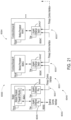
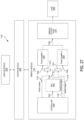
- FIG. 23 is a diagram of a modular energy system 1100 with dual power amplifiers, in accordance with at least one aspect of the present disclosure.
- the modular energy system 1100 is similar to the modular energy systems 1000, 2000, 3000, 6000 described hereinabove.
- the header module 1102 of the modular energy system 1100 shown in FIG. 23 is coupled to an energy module 1104 comprising dual power amplifiers 1106, 1108 as explained in the following description.
- the energy module 1104 includes a controller 1182 configured to control various communications and processing functions of the energy module 1104 and to generate a digital signal waveform representation of the analog signal waveform to be applied to a load 1140 coupled to the energy output port 1110 of the energy module 1104.
- the energy module 1104 can include a first power amplifier circuit 1106 and a second power amplifier circuit 1108, among various configurations of power amplifier circuits.
- the first power amplifier circuit 1106 may be characterized as having a first power rating and the second power amplifier circuit 1108 may be characterized as having a second power rating.
- the second power rating is greater than the first power rating.
- the first or second power amplifier circuit 1106, 1108 may be selected by a controller 1182 based on a desired power gain that is in the range of the power rating of the first or second power amplifier circuit 1106, 1108.
- the first power amplifier circuit 1106 can produce up to about 50 watts into a load 1140 coupled to the energy output port 1110 and in one aspect, the second power amplifier circuit 1108 can produce from about 50 to about 150 watts into a load 1140 coupled to the energy output port 1110 of the energy module 1104.
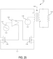
- the first power amplifier circuit 1106 may be a wideband (e.g., linear) power amplifier circuit as shown in FIG. 25 , for example, and the second power amplifier circuit 1108 may be a resonant (e.g., non-linear) power amplifier circuit as shown in FIG. 26 .
- the energy module 1104 includes a controller 1182 configured to control various communications and processing functions of the energy module 1104 and to generate a digital signal waveform representation of the analog signal waveform to be applied to the load 1140.
- the energy module 1104 can include a first power amplifier circuit 1106 and a second power amplifier circuit 1108, among various configurations of power amplifier circuits.
- the first power amplifier circuit 1106 may be a wideband (e.g., linear class) RF power amplifier circuit and the second power amplifier circuit 1108 may be a resonant (non-linear switch mode / flyback) RF power amplifier circuit such as, for example, a flyback modulated switching RF power amplifier circuit.
- FIG. 23 comprises two power amplifier circuits 1106, 1108, it is contemplated within the scope of the present disclosure that more than two power amplifier circuits 1106, 1108 may be employed to accommodate a variety of output power levels and efficiencies to deliver low power with highly refined waveforms in low energy surgery use cases and high power with high efficiency to mitigate predetermined thermal and power budgets of the modular energy system 1100 in high energy surgery use cases.
- the controller 1182 is electrically connected to a first power amplifier circuit 1106 that may be selected by a first amplifier select signal 1116 by the controller 1182.
- the controller 1182 also is electrically connected to a second power amplifier circuit 1108 that may be selected by a second amplifier select signal 1118 by the controller 1182. In this manner, the controller 1182 may select the first or second power amplifier circuit 1106, 1108 prior to outputting a digital waveform to the digital input 1132 of the DAC 1122.
- the energy module 1104 comprises a DAC 1122 electrically coupled to the controller 1182.
- the analog signal at the analog output 1134 of the DAC 1122 is applied to the input 1136 of the first power amplifier circuit 1106 and, in one aspect, may be applied to the input 1138 of the second power amplifier circuit 1108.
- a switching signal from the controller 1182 (or other microcontroller, computer, digital signal processor, digital timing circuit) may be applied to the input of the second power amplifier circuit 1108.
- the controller 1182 applies a digital signal to the digital input 1132 to the DAC 1122.
- the digital signal at the digital input 1132 of the DAC 1122 comprises digital output waveform segments defined by waveshape, input impedance (Z), current (I), power (P), voltage (V), and frequency (f) of the desired amplified analog signal at the output 1124 of the first or second power amplifier circuit 1106, 1108 that is applied to the load 1140 coupled to the energy output port 1110.
- the DAC 1122 converts the digital signal at the digital input 1132 of the DAC 1122 to an analog signal at the output 1134 of the DAC 1122.
- the analog signal at the output 1134 of the DAC 1122 is applied to the input 1136, 1138 of the first or second power amplifier circuit 1106, 1108 selected by the controller 1182 via the amplifier select signals 1116, 1118.
- the analog signal waveform delivered to the load 1140 coupled to the output port 1110 of the energy module 1104 may be defined in the controller 1182 software based on various parameters such as curve shape, input impedance (Z), current limit (i), power limit (p), voltage limit (v), and frequency (f).
- the shape of the output signal waveform may be defined by multiple segments that may be loaded by the controller 1182 software into the digital input 1132 of the DAC 1122 to generate a plurality of suitable analog signal waveshapes at the output 1134 of the DAC 1122.
- the controller 1182 Prior to loading the digital waveform segments into the digital input 1132 of the DAC 1122, the controller 1182 selects which power amplifier circuit 1106, 1108 to use to amplify the analog signal at the analog output 1134 of the DAC 1122 by power amplifier select signals 1116, 1118. Once the characteristics of the output signal waveform at the output 1124 is determined by the controller 1182, such as waveshape, impedance (Z), current (I), power (P), voltage (V), and frequency (f), the controller 1182 selects either the linear power amplifier 1106 or the non-linear power amplifier 1108 and then loads the digital signal into the digital input 1132 of the DAC 1122.
- Z impedance
- I current
- P power
- V voltage
- f frequency
- the first power amplifier circuits 1006, 1106 can be configured to drive low power output levels to the load 1040, 1140 coupled to the output port 1010, 1110 of the energy module 1004, 1104.
- Low power levels are preferably in the range of 1 to 60 watts; more preferably in the range of 1 to 50 watts; and still more preferably in the range of 1 to 40 watts.
- the fist power amplifier circuit 1006, 1106 can be an advanced wideband field effect transistor or bipolar junction transistor amplifier circuit or a similar amplifier.
- the first power amplifier 1006, 1106 can be a lower efficiency amplifier circuit but may provide greater control over waveshape and is well suited low power output applications.
- the first power amplifier circuit 1006, 1106 can operate within the power and heat requirements of the energy module 1004, 1104 and the modular energy system 1000, 1100. In addition to delivering low power levels, the first power amplifier circuit 1006, 1106 can be configured to deliver an output signal 1024, 1124 having a variety of waveshapes to the load 1040, 1140 coupled to the energy output port 1010, 1110 of the energy module 1004, 1104.
- the second power amplifier circuit 1008, 1108 can be configured to drive high power levels to a load 1040, 1140 coupled to the energy output port 1010, 1110 of the energy module 1004, 1104.
- High power levels are preferably in the range of 20 to 400 watts; more preferably in the range of 20 to 350 watts; and still more preferably in the range of 41 to 300 watts.
- the second power amplifier circuit 1008, 1108 can be a high power high efficiency resonant circuit or switch mode / flyback power amplifier circuit.
- the second power amplifier circuit 1008, 1108 may be configured to deliver high power levels at high efficiency but with less control waveform shape and frequency of the output signal 1024, 1124 supplied at the energy output port 1010, 1110 of the energy module 1004, 1104.
- the second power amplifier circuit 1008, 1108 can manage heat within the power budget of the energy module 1004, 1104 and the modular energy system 1000, 1100 due to its high efficiency rating.
- the controller 1082, 1182 can be configured to automatically switch between the first power amplifier circuit 1006, 1106 and the second power amplifier circuit 1008, 1108.
- the controller 1082, 1182 can be configured to switch between the first power amplifier circuit 1006, 1106 and the second power amplifier circuit 1008, 1108 based on user inputs entered via the user interface 1030, 1130 of the header module 1002, 1102 of the modular energy system 1000, 1100.
- the switchover between the first power amplifier circuit 1006, 1106 and the second power amplifier circuit 1008, 1108 is seamless to the user.
- the user interface 1030, 1130 coupled to the header module 1002, 1102 may highlight to the user which power amplifier 1006, 1106, 1008, 1108 is currently in use and may enable the user to select one or the or the other power amplifier circuit 1006, 1106, 1008, 1108 based on the type of surgical instrument coupled to the energy output port 1010, 1110 of the energy module 1004, 1104.
- Such options include, for example, a monopolar RF instrument, a bipolar RF instrument, or a combination ultrasonic / RF instrument (either monopolar or bipolar).
- the hardware (circuits / relays) implementation of the power amplifier circuits 1006, 1106, 1008, 1108 may be fixed at the manufacturing stage and the configuration of the power amplifier circuits 1006, 1106, 1008, 1108 may be updated in the field to enable and optimize when and how to use each power amplifier circuit 1006, 1106, 1008, 1108 by way of software updates, even after the energy modules 1002, 1104 are sold, shipped, and / or are installed in the field.
- the software of the modular energy system 1000, 1100 can be updated to refine the energy output based on a particular application.
- Traditional techniques of updating software on the controller 1082, 1182 required the software to be recompiled, a quality check, and multiple releases of the software due to limited bandwidth.
- the software tools for operating the controller 1082, 1182 of the modular energy system 1000, 1100 are configured to convert the models into ".ini" configuration files comprising text-based content as shown in TABLE 1, for example, with a structure and syntax comprising key-value pairs for properties, and sections that organize the properties with all the set points with many iterations and refinements such as, for example, waveshape, input impedance (Input_z), current limit (Limit_i), power limit (Limit_p), and voltage limit (Lmit_v) for each curve segment of the desired output signal 1024, 1124.
- the validated software is capable of always producing energy within some bounds that are safe and effective.
- refinements are capable of being made via files that are not the core software, and are updated more quickly than typical firmware upgrades of the energy module 1004, 1104.
- FIG. 24 is a flow diagram of a method 1150 of delivering power to a load 1040, 1140 by an energy module 1000, 1100, in accordance with at least one aspect of the present disclosure.
- the controller 1082, 1182 generates 1152 a digital waveform having a predetermined wave shape and frequency.
- the controller 1082, 1182 is coupled to the DAC 1022, 1122.
- the DAC 1022, 1122 converts 1154 the digital waveform to an analog waveform.
- the controller 1082, 1182 selects 1156 a first power amplifier circuit 1006, 1106 or a second power amplifier circuit 1008, 1108 based on a predetermined power output to be produced by the first power amplifier circuit 1006, 1106 or the second power amplifier circuit 1008, 1108 into a load 1040, 1140 coupled to an energy output port 1010, 1110 of the energy module 1000, 1100.
- the controller 1082, 1182 couples 1158 the analog waveform to the selected first power amplifier circuit 1006, 1106 or the second power amplifier circuit 1008, 1108.
- the selected first power amplifier circuit 1006, 1106 or second power amplifier circuit 1008, 1108 produces 1160 the predetermined power output into the load 1040, 1140 coupled to the energy output port 1010, 1110 of the energy module 1000, 1100.
- the controller 1082, 1182 applies a switching signal to the input of the second amplifier circuit 1008, 1108, as explained in the description of FIG. 26 , for example.
- the controller 1082 selects a first switch 1012 coupled between the DAC 1022 and the first power amplifier circuit 1006 to produce a first power output into the load 1040 coupled to the output 1024 of the first power amplifier circuit 1006 through the energy output port 1010.
- the controller 1082 selects a second switch 1014 coupled between the DAC 1022 and the second power amplifier circuit 1008 to produce a second power output into the load 1040 coupled to the output 1024 of the second power amplifier circuit 1008 through the energy output port 1010.
Landscapes
- Health & Medical Sciences (AREA)
- Engineering & Computer Science (AREA)
- Life Sciences & Earth Sciences (AREA)
- Surgery (AREA)
- Medical Informatics (AREA)
- General Health & Medical Sciences (AREA)
- Otolaryngology (AREA)
- Physics & Mathematics (AREA)
- Power Engineering (AREA)
- Biomedical Technology (AREA)
- Nuclear Medicine, Radiotherapy & Molecular Imaging (AREA)
- Molecular Biology (AREA)
- Heart & Thoracic Surgery (AREA)
- Animal Behavior & Ethology (AREA)
- Plasma & Fusion (AREA)
- Public Health (AREA)
- Veterinary Medicine (AREA)
- Surgical Instruments (AREA)
- Amplifiers (AREA)
Claims (14)
- Energiemodul (1004, 1191) zum Erzeugen von elektrochirurgischer Energie, Ultraschallenergie oder einer Kombination davon, wobei das Energiemodul umfasst:eine Steuerung (1082);eine erste Leistungsverstärkerschaltung (1006) mit einem Eingang und einem Ausgang, wobei der Eingang mit der Steuerung gekoppelt ist und konfiguriert ist, um ein Eingangssignal zu empfangen und zu verstärken, um ein erstes Ausgangssignal in eine Last (1040) zu erzeugen, die mit dem Ausgang der ersten Leistungsverstärkerschaltung gekoppelt ist;eine zweite Leistungsverstärkerschaltung (1008) mit einem Eingang und einem Ausgang, wobei der Eingang mit der Steuerung gekoppelt ist und konfiguriert ist, um das Eingangssignal zu empfangen und zu verstärken, um ein zweites Ausgangssignal in eine Last zu erzeugen, die mit dem Ausgang der zweiten Leistungsverstärkerschaltung gekoppelt ist;wobei die erste Leistungsverstärkerschaltung eine Breitband-Leistungsverstärkerschaltung und die zweite Leistungsverstärkerschaltung (1008) eine Resonanz-Leistungsverstärkerschaltung ist,wobei die Steuerung (1082) konfiguriert ist, um eine Wellenform mit einer vorbestimmten Wellengestalt und Frequenz basierend auf der Last (1040) zu erzeugen, die mit dem Ausgang der ersten oder der zweiten Leistungsverstärkerschaltung (1006, 1008) gekoppelt ist, undferner umfassend einen Digital-Analog-Wandler, der zwischen die Steuerung und mindestens eine der ersten und der zweiten Leistungsverstärkerschaltung gekoppelt ist, wobei der Digital-Analog-Wandler (1022) konfiguriert ist, um die Wellenform in digitaler Form zu empfangen und eine analoge Wellenform dem Eingang der mindestens einen der ersten oder der zweiten Leistungsverstärkerschaltung (1006, 1008) bereitzustellen,dadurch gekennzeichnet, dass eine Nennleistung der ersten Verstärkerschaltung von einer Nennleistung der zweiten Verstärkerschaltung verschieden ist; und dass die Steuerung konfiguriert ist, um die erste oder die zweite Leistungsverstärkerschaltung basierend auf der in der Last zu erzeugenden Leistung auszuwählen.
- Energiemodul (1004, 1191) nach Anspruch 1, wobei die Nennleistung der ersten Leistungsverstärkerschaltung (1006) geringer ist als die Nennleistung der zweiten Leistungsverstärkerschaltung (1008).
- Energiemodul (1004, 1191) nach Anspruch 2, wobei die Nennleistung der ersten Leistungsverstärkerschaltung (1006) in einem Bereich von 1 bis 60 Watt liegt, und/oder wobei die Nennleistung der zweiten Verstärkerschaltung (1008) in einem Bereich von 20 bis 400 Watt liegt, und/oder wobei die Nennleistung der zweiten Leistungsverstärkerschaltung höher ist als die Nennleistung der ersten Leistungsverstärkerschaltung.
- Energiemodul (1004, 1191) nach einem der vorstehenden Ansprüche, wobei mindestens eine der ersten oder der zweiten Leistungsverstärkerschaltung (1006, 1008) einen Schaltkreis umfasst und wobei die Steuerung (1082) konfiguriert ist, um ein Schaltsignal an den Schaltkreis der mindestens einen der ersten oder der zweiten Leistungsverstärkerschaltung anzulegen.
- Energiemodul (1004, 1191) nach Anspruch 4, wobei die erste Leistungsverstärkerschaltung (1006) einen ersten Schaltkreis umfasst und die zweite Leistungsverstärkerschaltung (1008) einen zweiten Schaltkreis umfasst und wobei die Steuerung (1082) konfiguriert ist, um ein erstes Schaltsignal an den ersten Schaltkreis und ein zweites Schaltsignal an die zweite Leistungsverstärkerschaltung anzulegen.
- Energiemodul (1191) nach Anspruch 4, ferner umfassend einen Digital-Analog-Wandler (1022), der zwischen die Steuerung (1082) und die erste Leistungsverstärkerschaltung (1006) gekoppelt ist, wobei die zweite Leistungsverstärkerschaltung (1008) den Schaltkreis umfasst und wobei die Steuerung konfiguriert ist, um das Schaltsignal an die zweite Verstärkerschaltung anzulegen.
- Energiemodul (1004, 1191) nach einem der vorstehenden Ansprüche, wobei die Steuerung konfiguriert ist, um Strom, Leistung und Spannung der Wellenform basierend auf der Impedanz der mit dem Ausgang der ersten oder der zweiten Leistungsverstärkerschaltung gekoppelten Last zu begrenzen.
- Energiemodul nach Anspruch 7, wobei die Steuerung konfiguriert ist, um mindestens eine der ersten oder der zweiten Leistungsverstärkerschaltung basierend auf der Leistung auszuwählen, die in der mit dem Ausgang der mindestens einen der ersten oder der zweiten Leistungsverstärkerschaltung gekoppelten Last erzeugt werden soll.
- Energiemodul (1004, 1191) nach Anspruch 7, wobei der Digital-Analog-Wandler konfiguriert ist, um die analoge Wellenform dem Eingang entweder der ersten oder der zweiten Leistungsverstärkerschaltung basierend auf der Leistung bereitzustellen, die in der mit dem Ausgang der ersten oder der zweiten Leistungsverstärkerschaltung gekoppelten Last (1020) erzeugt werden soll.
- Energiemodul nach Anspruch 9, ferner umfassend:einen ersten Schalter, der zwischen den Ausgang des Digital-Analog-Wandlers und den Eingang der ersten Leistungsverstärkerschaltung gekoppelt ist; undeinen zweiten Schalter, der zwischen den Ausgang des Digital-Analog-Wandlers und den Eingang des zweiten Leistungsverstärkereingangs gekoppelt ist;wobei der erste und der zweite Schalter von der Steuerung über eine erste und eine zweite Schalterauswahlleitung gesteuert werden, um die erste oder die zweite Leistungsverstärkerschaltung basierend der Leistung auszuwählen, die in der mit dem Ausgang der ersten oder der zweiten Leistungsverstärkerschaltung gekoppelten Last erzeugt werden soll.
- Energiemodul nach Anspruch 9, wobei die erste oder die zweite Leistungsverstärkerschaltung durch die Steuerung auswählbar ist und wobei die Steuerung konfiguriert ist, um die erste oder die zweite Leistungsverstärkerschaltung basierend auf der Leistung auszuwählen, die in der mit dem Ausgang der ersten oder der zweiten Leistungsverstärkerschaltung gekoppelten Last erzeugt werden soll.
- Energiemodul nach Anspruch 9, wobei das Auswählen der ersten Leistungsverstärkerschaltung oder der zweiten Leistungsverstärkerschaltung umfasst:Auswählen eines ersten Schalters, der zwischen den Digital-Analog-Wandler und die erste Leistungsverstärkerschaltung gekoppelt ist, um eine erste Ausgangsleistung in die Last zu erzeugen, die über den Energieausgangsanschluss mit dem Ausgang der ersten Leistungsverstärkerschaltung gekoppelt ist; oderAuswählen eines zweiten Schalters, der zwischen den Digital-Analog-Wandler und die zweite Leistungsverstärkerschaltung gekoppelt ist, um eine zweite Ausgangsleistung in die Last zu erzeugen, die über den Energieausgangsanschluss mit dem Ausgang der zweiten Leistungsverstärkerschaltung gekoppelt ist,oder wobei das Auswählen der ersten Leistungsverstärkerschaltung oder der zweiten Leistungsverstärkerschaltung umfasst:Auswählen der ersten Leistungsverstärkerschaltung über ein erstes Verstärkerauswahlsignal, um eine erste Ausgangsleistung in die Last zu erzeugen, die über den Energieausgangsanschluss mit dem Ausgang der ersten Leistungsverstärkerschaltung gekoppelt ist; oderAuswählen der zweiten Leistungsverstärkerschaltung über ein zweites Verstärkerauswahlsignal, um eine zweite Ausgangsleistung in die Last zu erzeugen, die über den Energieausgangsanschluss mit dem Ausgang der zweiten Leistungsverstärkerschaltung gekoppelt ist.
- Energiemodul (1104, 1194) nach Anspruch 9 oder 12, wobei die Steuerung (1182) konfiguriert ist, um die Last (1140) zu bestimmen, die mit dem Ausgang des Energiemoduls gekoppelt ist,
wobei optional die Steuerung ferner konfiguriert ist, um Strom, Leistung und Spannung der Wellenform basierend auf einer Impedanz der mit dem Ausgang der ersten oder der zweiten Leistungsverstärkerschaltung gekoppelten Last zu begrenzen. - Energiemodul (1104, 1194) nach einem der Ansprüche 9 bis 13, wobei die Steuerung (1182) konfiguriert ist zum:
Anlegen eines Schaltsignals an den Eingang der zweiten Leistungsverstärkerschaltung (1108).
Priority Applications (1)
| Application Number | Priority Date | Filing Date | Title |
|---|---|---|---|
| EP25185129.1A EP4601191A3 (de) | 2021-03-30 | 2022-03-28 | Energiemodul mit zwei leistungsverstärkern |
Applications Claiming Priority (3)
| Application Number | Priority Date | Filing Date | Title |
|---|---|---|---|
| US17/217,439 US12040749B2 (en) | 2021-03-30 | 2021-03-30 | Modular energy system with dual amplifiers and techniques for updating parameters thereof |
| US17/217,424 US12228987B2 (en) | 2021-03-30 | 2021-03-30 | Method for energy delivery for modular energy system |
| PCT/IB2022/052837 WO2022208314A1 (en) | 2021-03-30 | 2022-03-28 | Energy module with dual power amplifiers |
Related Child Applications (1)
| Application Number | Title | Priority Date | Filing Date |
|---|---|---|---|
| EP25185129.1A Division EP4601191A3 (de) | 2021-03-30 | 2022-03-28 | Energiemodul mit zwei leistungsverstärkern |
Publications (3)
| Publication Number | Publication Date |
|---|---|
| EP4132402A1 EP4132402A1 (de) | 2023-02-15 |
| EP4132402C0 EP4132402C0 (de) | 2025-07-09 |
| EP4132402B1 true EP4132402B1 (de) | 2025-07-09 |
Family
ID=81326364
Family Applications (2)
| Application Number | Title | Priority Date | Filing Date |
|---|---|---|---|
| EP25185129.1A Pending EP4601191A3 (de) | 2021-03-30 | 2022-03-28 | Energiemodul mit zwei leistungsverstärkern |
| EP22714585.1A Active EP4132402B1 (de) | 2021-03-30 | 2022-03-28 | Energiemodul mit zwei leistungsverstärkern |
Family Applications Before (1)
| Application Number | Title | Priority Date | Filing Date |
|---|---|---|---|
| EP25185129.1A Pending EP4601191A3 (de) | 2021-03-30 | 2022-03-28 | Energiemodul mit zwei leistungsverstärkern |
Country Status (4)
| Country | Link |
|---|---|
| EP (2) | EP4601191A3 (de) |
| JP (1) | JP2024516524A (de) |
| BR (1) | BR112023020255A2 (de) |
| WO (1) | WO2022208314A1 (de) |
Families Citing this family (1)
| Publication number | Priority date | Publication date | Assignee | Title |
|---|---|---|---|---|
| WO2026023078A1 (ja) * | 2024-07-26 | 2026-01-29 | オリンパスメディカルシステムズ株式会社 | 制御装置 |
Citations (1)
| Publication number | Priority date | Publication date | Assignee | Title |
|---|---|---|---|---|
| US20200078083A1 (en) * | 2017-04-28 | 2020-03-12 | Stryker Corporation | Control Console And Accessories For RF Nerve Ablation And Methods Of Operating The Same |
Family Cites Families (14)
| Publication number | Priority date | Publication date | Assignee | Title |
|---|---|---|---|---|
| GB8401887D0 (en) * | 1984-01-25 | 1984-02-29 | Matburn Holdings Ltd | Electrosurgical unit |
| US4712544A (en) * | 1986-02-12 | 1987-12-15 | Castle Company | Electrosurgical generator |
| FI106412B (fi) * | 1998-11-10 | 2001-01-31 | Nokia Mobile Phones Ltd | Lineaarinen tehovahvistinjärjestely ja menetelmä sen käyttämiseksi |
| KR101800728B1 (ko) * | 2011-10-14 | 2017-11-24 | 삼성전자주식회사 | 전력 증폭기의 동작 영역을 확대하기 위한 장치 및 방법 |
| US10363084B2 (en) * | 2015-04-01 | 2019-07-30 | Covidien Lp | Interdigitation of waveforms for dual-output electrosurgical generators |
| US10194973B2 (en) | 2015-09-30 | 2019-02-05 | Ethicon Llc | Generator for digitally generating electrical signal waveforms for electrosurgical and ultrasonic surgical instruments |
| US12144136B2 (en) | 2018-09-07 | 2024-11-12 | Cilag Gmbh International | Modular surgical energy system with module positional awareness with digital logic |
| US11923084B2 (en) | 2018-09-07 | 2024-03-05 | Cilag Gmbh International | First and second communication protocol arrangement for driving primary and secondary devices through a single port |
| US12035956B2 (en) | 2018-09-07 | 2024-07-16 | Cilag Gmbh International | Instrument tracking arrangement based on real time clock information |
| US11804679B2 (en) | 2018-09-07 | 2023-10-31 | Cilag Gmbh International | Flexible hand-switch circuit |
| US11471206B2 (en) | 2018-09-07 | 2022-10-18 | Cilag Gmbh International | Method for controlling a modular energy system user interface |
| US11743665B2 (en) | 2019-03-29 | 2023-08-29 | Cilag Gmbh International | Modular surgical energy system with module positional awareness sensing with time counter |
| US20200305924A1 (en) | 2019-03-29 | 2020-10-01 | Ethicon Llc | Automatic ultrasonic energy activation circuit design for modular surgical systems |
| US11411536B2 (en) * | 2019-07-17 | 2022-08-09 | The Board Of Trustees Of The Leland Stanford Junior University | Power amplifier with each of multiple in-parallel circuits having power amplification and immittance conversion |
-
2022
- 2022-03-28 JP JP2023560575A patent/JP2024516524A/ja active Pending
- 2022-03-28 BR BR112023020255A patent/BR112023020255A2/pt unknown
- 2022-03-28 EP EP25185129.1A patent/EP4601191A3/de active Pending
- 2022-03-28 WO PCT/IB2022/052837 patent/WO2022208314A1/en not_active Ceased
- 2022-03-28 EP EP22714585.1A patent/EP4132402B1/de active Active
Patent Citations (1)
| Publication number | Priority date | Publication date | Assignee | Title |
|---|---|---|---|---|
| US20200078083A1 (en) * | 2017-04-28 | 2020-03-12 | Stryker Corporation | Control Console And Accessories For RF Nerve Ablation And Methods Of Operating The Same |
Also Published As
| Publication number | Publication date |
|---|---|
| WO2022208314A1 (en) | 2022-10-06 |
| EP4132402C0 (de) | 2025-07-09 |
| EP4601191A3 (de) | 2026-02-18 |
| EP4601191A2 (de) | 2025-08-13 |
| EP4132402A1 (de) | 2023-02-15 |
| BR112023020255A2 (pt) | 2024-02-15 |
| JP2024516524A (ja) | 2024-04-16 |
Similar Documents
| Publication | Publication Date | Title |
|---|---|---|
| US12040749B2 (en) | Modular energy system with dual amplifiers and techniques for updating parameters thereof | |
| EP4171414B1 (de) | Systemarchitektur für modulares energiesystem | |
| EP4125659B1 (de) | Energieversorgung für modulare energiesysteme | |
| US20250216918A1 (en) | Method for energy delivery for modular energy system | |
| US12369994B2 (en) | Modular energy system with multi-energy port splitter for multiple energy devices | |
| US20260044474A1 (en) | Intelligent data ports for modular energy systems | |
| EP4125661B1 (de) | Modulares energiesystem mit hardware-begrenzter kommunikation | |
| US11950860B2 (en) | User interface mitigation techniques for modular energy systems | |
| US11978554B2 (en) | Radio frequency identification token for wireless surgical instruments | |
| US12004824B2 (en) | Architecture for modular energy system | |
| US20220313369A1 (en) | Method for intelligent instruments for modular energy system | |
| US20230414298A1 (en) | Surgical footswitch assignment for modular energy system | |
| EP4132402B1 (de) | Energiemodul mit zwei leistungsverstärkern |
Legal Events
| Date | Code | Title | Description |
|---|---|---|---|
| STAA | Information on the status of an ep patent application or granted ep patent |
Free format text: STATUS: UNKNOWN |
|
| STAA | Information on the status of an ep patent application or granted ep patent |
Free format text: STATUS: THE INTERNATIONAL PUBLICATION HAS BEEN MADE |
|
| PUAI | Public reference made under article 153(3) epc to a published international application that has entered the european phase |
Free format text: ORIGINAL CODE: 0009012 |
|
| STAA | Information on the status of an ep patent application or granted ep patent |
Free format text: STATUS: REQUEST FOR EXAMINATION WAS MADE |
|
| 17P | Request for examination filed |
Effective date: 20221107 |
|
| AK | Designated contracting states |
Kind code of ref document: A1 Designated state(s): AL AT BE BG CH CY CZ DE DK EE ES FI FR GB GR HR HU IE IS IT LI LT LU LV MC MK MT NL NO PL PT RO RS SE SI SK SM TR |
|
| RIN1 | Information on inventor provided before grant (corrected) |
Inventor name: WIENER, EITAN T. Inventor name: SAMUEL, JONATHAN T. |
|
| STAA | Information on the status of an ep patent application or granted ep patent |
Free format text: STATUS: EXAMINATION IS IN PROGRESS |
|
| 17Q | First examination report despatched |
Effective date: 20231016 |
|
| RIC1 | Information provided on ipc code assigned before grant |
Ipc: H02J 3/00 20060101ALN20240325BHEP Ipc: H03F 1/02 20060101ALI20240325BHEP Ipc: A61B 18/12 20060101AFI20240325BHEP |
|
| GRAP | Despatch of communication of intention to grant a patent |
Free format text: ORIGINAL CODE: EPIDOSNIGR1 |
|
| STAA | Information on the status of an ep patent application or granted ep patent |
Free format text: STATUS: GRANT OF PATENT IS INTENDED |
|
| INTG | Intention to grant announced |
Effective date: 20240507 |
|
| RIC1 | Information provided on ipc code assigned before grant |
Ipc: H02J 3/00 20060101ALN20240424BHEP Ipc: H03F 1/02 20060101ALI20240424BHEP Ipc: A61B 18/12 20060101AFI20240424BHEP |
|
| DAV | Request for validation of the european patent (deleted) | ||
| DAX | Request for extension of the european patent (deleted) | ||
| GRAJ | Information related to disapproval of communication of intention to grant by the applicant or resumption of examination proceedings by the epo deleted |
Free format text: ORIGINAL CODE: EPIDOSDIGR1 |
|
| STAA | Information on the status of an ep patent application or granted ep patent |
Free format text: STATUS: EXAMINATION IS IN PROGRESS |
|
| GRAP | Despatch of communication of intention to grant a patent |
Free format text: ORIGINAL CODE: EPIDOSNIGR1 |
|
| STAA | Information on the status of an ep patent application or granted ep patent |
Free format text: STATUS: GRANT OF PATENT IS INTENDED |
|
| INTC | Intention to grant announced (deleted) | ||
| INTG | Intention to grant announced |
Effective date: 20241206 |
|
| RIC1 | Information provided on ipc code assigned before grant |
Ipc: H02J 3/00 20060101ALN20241202BHEP Ipc: H03F 1/02 20060101ALI20241202BHEP Ipc: A61B 18/12 20060101AFI20241202BHEP |
|
| GRAS | Grant fee paid |
Free format text: ORIGINAL CODE: EPIDOSNIGR3 |
|
| GRAA | (expected) grant |
Free format text: ORIGINAL CODE: 0009210 |
|
| STAA | Information on the status of an ep patent application or granted ep patent |
Free format text: STATUS: THE PATENT HAS BEEN GRANTED |
|
| AK | Designated contracting states |
Kind code of ref document: B1 Designated state(s): AL AT BE BG CH CY CZ DE DK EE ES FI FR GB GR HR HU IE IS IT LI LT LU LV MC MK MT NL NO PL PT RO RS SE SI SK SM TR |
|
| REG | Reference to a national code |
Ref country code: GB Ref legal event code: FG4D |
|
| REG | Reference to a national code |
Ref country code: CH Ref legal event code: EP |
|
| REG | Reference to a national code |
Ref country code: IE Ref legal event code: FG4D |
|
| REG | Reference to a national code |
Ref country code: DE Ref legal event code: R096 Ref document number: 602022017307 Country of ref document: DE |
|
| U01 | Request for unitary effect filed |
Effective date: 20250804 |
|
| U07 | Unitary effect registered |
Designated state(s): AT BE BG DE DK EE FI FR IT LT LU LV MT NL PT RO SE SI Effective date: 20250812 |
|
| PG25 | Lapsed in a contracting state [announced via postgrant information from national office to epo] |
Ref country code: IS Free format text: LAPSE BECAUSE OF FAILURE TO SUBMIT A TRANSLATION OF THE DESCRIPTION OR TO PAY THE FEE WITHIN THE PRESCRIBED TIME-LIMIT Effective date: 20251109 |
|
| PG25 | Lapsed in a contracting state [announced via postgrant information from national office to epo] |
Ref country code: NO Free format text: LAPSE BECAUSE OF FAILURE TO SUBMIT A TRANSLATION OF THE DESCRIPTION OR TO PAY THE FEE WITHIN THE PRESCRIBED TIME-LIMIT Effective date: 20251009 |
|
| PG25 | Lapsed in a contracting state [announced via postgrant information from national office to epo] |
Ref country code: HR Free format text: LAPSE BECAUSE OF FAILURE TO SUBMIT A TRANSLATION OF THE DESCRIPTION OR TO PAY THE FEE WITHIN THE PRESCRIBED TIME-LIMIT Effective date: 20250709 |
|
| PG25 | Lapsed in a contracting state [announced via postgrant information from national office to epo] |
Ref country code: GR Free format text: LAPSE BECAUSE OF FAILURE TO SUBMIT A TRANSLATION OF THE DESCRIPTION OR TO PAY THE FEE WITHIN THE PRESCRIBED TIME-LIMIT Effective date: 20251010 |
|
| PG25 | Lapsed in a contracting state [announced via postgrant information from national office to epo] |
Ref country code: PL Free format text: LAPSE BECAUSE OF FAILURE TO SUBMIT A TRANSLATION OF THE DESCRIPTION OR TO PAY THE FEE WITHIN THE PRESCRIBED TIME-LIMIT Effective date: 20250709 |
|
| PG25 | Lapsed in a contracting state [announced via postgrant information from national office to epo] |
Ref country code: RS Free format text: LAPSE BECAUSE OF FAILURE TO SUBMIT A TRANSLATION OF THE DESCRIPTION OR TO PAY THE FEE WITHIN THE PRESCRIBED TIME-LIMIT Effective date: 20251009 |
|
| PG25 | Lapsed in a contracting state [announced via postgrant information from national office to epo] |
Ref country code: ES Free format text: LAPSE BECAUSE OF FAILURE TO SUBMIT A TRANSLATION OF THE DESCRIPTION OR TO PAY THE FEE WITHIN THE PRESCRIBED TIME-LIMIT Effective date: 20250709 |
|
| U20 | Renewal fee for the european patent with unitary effect paid |
Year of fee payment: 5 Effective date: 20260209 |
|
| PG25 | Lapsed in a contracting state [announced via postgrant information from national office to epo] |
Ref country code: SM Free format text: LAPSE BECAUSE OF FAILURE TO SUBMIT A TRANSLATION OF THE DESCRIPTION OR TO PAY THE FEE WITHIN THE PRESCRIBED TIME-LIMIT Effective date: 20250709 |
|
| PGFP | Annual fee paid to national office [announced via postgrant information from national office to epo] |
Ref country code: GB Payment date: 20260209 Year of fee payment: 5 |