EP4132089B1 - Verfahren zur bestimmung des drx-modus und kommunikationsvorrichtung - Google Patents
Verfahren zur bestimmung des drx-modus und kommunikationsvorrichtung Download PDFInfo
- Publication number
- EP4132089B1 EP4132089B1 EP21787615.0A EP21787615A EP4132089B1 EP 4132089 B1 EP4132089 B1 EP 4132089B1 EP 21787615 A EP21787615 A EP 21787615A EP 4132089 B1 EP4132089 B1 EP 4132089B1
- Authority
- EP
- European Patent Office
- Prior art keywords
- terminal device
- duration
- resource
- timer
- drx
- Prior art date
- Legal status (The legal status is an assumption and is not a legal conclusion. Google has not performed a legal analysis and makes no representation as to the accuracy of the status listed.)
- Active
Links
Images


Classifications
-
- H—ELECTRICITY
- H04—ELECTRIC COMMUNICATION TECHNIQUE
- H04W—WIRELESS COMMUNICATION NETWORKS
- H04W76/00—Connection management
- H04W76/20—Manipulation of established connections
- H04W76/28—Discontinuous transmission [DTX]; Discontinuous reception [DRX]
-
- H—ELECTRICITY
- H04—ELECTRIC COMMUNICATION TECHNIQUE
- H04W—WIRELESS COMMUNICATION NETWORKS
- H04W28/00—Network traffic management; Network resource management
- H04W28/16—Central resource management; Negotiation of resources or communication parameters, e.g. negotiating bandwidth or QoS [Quality of Service]
- H04W28/26—Resource reservation
-
- H—ELECTRICITY
- H04—ELECTRIC COMMUNICATION TECHNIQUE
- H04W—WIRELESS COMMUNICATION NETWORKS
- H04W72/00—Local resource management
- H04W72/04—Wireless resource allocation
- H04W72/044—Wireless resource allocation based on the type of the allocated resource
- H04W72/0446—Resources in time domain, e.g. slots or frames
-
- H—ELECTRICITY
- H04—ELECTRIC COMMUNICATION TECHNIQUE
- H04W—WIRELESS COMMUNICATION NETWORKS
- H04W76/00—Connection management
- H04W76/10—Connection setup
- H04W76/14—Direct-mode setup
-
- H—ELECTRICITY
- H04—ELECTRIC COMMUNICATION TECHNIQUE
- H04W—WIRELESS COMMUNICATION NETWORKS
- H04W92/00—Interfaces specially adapted for wireless communication networks
- H04W92/16—Interfaces between hierarchically similar devices
- H04W92/20—Interfaces between hierarchically similar devices between access points
-
- Y—GENERAL TAGGING OF NEW TECHNOLOGICAL DEVELOPMENTS; GENERAL TAGGING OF CROSS-SECTIONAL TECHNOLOGIES SPANNING OVER SEVERAL SECTIONS OF THE IPC; TECHNICAL SUBJECTS COVERED BY FORMER USPC CROSS-REFERENCE ART COLLECTIONS [XRACs] AND DIGESTS
- Y02—TECHNOLOGIES OR APPLICATIONS FOR MITIGATION OR ADAPTATION AGAINST CLIMATE CHANGE
- Y02D—CLIMATE CHANGE MITIGATION TECHNOLOGIES IN INFORMATION AND COMMUNICATION TECHNOLOGIES [ICT], I.E. INFORMATION AND COMMUNICATION TECHNOLOGIES AIMING AT THE REDUCTION OF THEIR OWN ENERGY USE
- Y02D30/00—Reducing energy consumption in communication networks
- Y02D30/70—Reducing energy consumption in communication networks in wireless communication networks
Definitions
- Embodiments of this application relate to the field of communication technologies, and in particular, to a DRX mode determining method and a communication apparatus.
- a sidelink resource is a resource used for communication between terminal devices.
- the sidelink resource may include a frequency domain sidelink resource and a time domain sidelink resource.
- Embodiments of this application provide a DRX mode determining method according to claim 1 and a communication apparatus according to claim 11, to reduce power consumption of a terminal device in a sidelink.
- the terminal device determines the first DRX mode based on a status of overlapping between the time domain resource and an on duration of a candidate DRX mode, where the status of overlapping includes whether overlapping occurs and/or an overlapping degree.
- a corresponding DRX mode may be selected based on a reserved time domain resource, where the DRX mode can match the reserved time domain resource, to ensure that the reserved time domain resource can be effectively used. This can improve data transmission efficiency, and can reduce power consumption of the terminal device.
- the terminal device may select a DRX mode from the candidate DRX mode based on the status of overlapping between the time domain resource and the on duration of the candidate DRX mode.
- the on duration of the finally selected first DRX mode can fully or partially cover the time domain location of the time domain resource, so that the reserved time domain resource can be effectively used. This can improve data transmission efficiency, and can reduce power consumption of the terminal device.
- the candidate DRX mode includes a DRX mode configured for a sidelink resource pool, or includes a DRX mode configured for a sidelink.
- a DRX mode may be configured at a granularity of a resource pool, or a DRX mode may be configured at a granularity of a sidelink, so that implementation is flexible.
- the time domain resource includes the first resource set, and at least one of the N resources in the first resource set is included in the on duration of the first DRX mode, or the first m symbols of at least one of the N resources in the first resource set overlap the on duration of the first DRX mode.
- the time domain resource includes the second resource set, and the first resource of N resources in a target period in the second resource set is included in the on duration of the first DRX mode, or the first m symbols of the first resource of N resources in a target period in the second resource set overlap the on duration of the first DRX mode.
- the target period is at least one of the first Y periods corresponding to the second resource set, and Y is a positive integer. This solution is applicable to a periodic service or a periodic reserved resource.
- the terminal device is a receive-side terminal device
- the receive-side terminal device receives indication information from a transmit-side terminal device or a network device, where the indication information is used to indicate a type of a DRX inactivity timer, and the type of the DRX inactivity timer is a first timer or a second timer.
- the first timer is a DRX inactivity timer with a configured duration
- the second timer is a DRX inactivity timer with a variable duration
- the first timer is a DRX inactivity timer with a first duration
- the second timer is a DRX inactivity timer with a second duration
- the first duration is configured by the network device or the transmit-side terminal device
- the second duration is determined by the transmit-end terminal device or the receive-end terminal device.
- the second duration is associated with the time domain of the time domain resource or a duration occupied by the time domain resource.
- the receive-side terminal device may use the first timer or the second timer, so that the DRX inactivity timer can well match the selected first DRX mode and a reserved sidelink resource. This ensures that the reserved time domain resource can fall within the on duration of the first DRX mode to the greatest extent, so that the terminal device can maximize use of the reserved resource, thereby improving resource utilization and communication efficiency.
- the terminal device is a transmit-side terminal device, and the transmit-side terminal device sends indication information to a receive-side terminal device, where the indication information is used to indicate a type of a DRX inactivity timer, and the type of the DRX inactivity timer is a first timer or a second timer.
- the first timer is a DRX inactivity timer with a configured duration
- the second timer is a DRX inactivity timer with a variable duration
- the first timer is a DRX inactivity timer with a first duration
- the second timer is a DRX inactivity timer with a second duration
- the first duration is configured by a network device or the transmit-side terminal device
- the second duration is determined by the transmit-end terminal device or the receive-end terminal device.
- the second duration is associated with the time domain of the time domain resource or a duration occupied by the time domain resource.
- the transmit-side terminal device determines the type of the to-be-used DRX inactivity timer, and sends the type of the DRX inactivity timer to the receive-side terminal device.
- the receive-side terminal device may use the first timer or the second timer, so that the DRX inactivity timer can well match the selected first DRX mode and a reserved sidelink resource. This ensures that the reserved time domain resource can fall within the on duration of the first DRX mode to the greatest extent, so that the terminal device can maximize use of the reserved resource, thereby improving resource utilization and communication efficiency.
- the terminal device is a receive-side terminal device or a transmit-side terminal device, and the terminal device determines, based on the status of overlapping between the on duration of the first DRX mode and the time domain resource, to use the first timer or the second timer, where the status of overlapping includes whether overlapping occurs and/or an overlapping degree.
- the first timer is a DRX inactivity timer with a configured duration
- the second timer is a DRX inactivity timer with a variable duration
- the first timer is a DRX inactivity timer with a first duration
- the second timer is a DRX inactivity timer with a second duration
- the first duration is configured by a network device or the transmit-side terminal device
- the second duration is determined by the transmit-end terminal device or the receive-end terminal device.
- the second duration is associated with the time domain of the time domain resource or a duration occupied by the time domain resource.
- the transmit-side terminal device or the receive-side terminal device determines the type of the to-be-used DRX inactivity timer based on the status of overlapping between the on duration of the selected first DRX mode and the time domain resource.
- the receive-side terminal device may use the first timer or the second timer, so that the DRX inactivity timer can well match the selected first DRX mode and a reserved sidelink resource. This ensures that the reserved time domain resource can fall within the on duration of the first DRX mode to the greatest extent, so that the terminal device can maximize use of the reserved resource, thereby improving resource utilization and communication efficiency.
- the terminal device is a transmit-side terminal device, and that a terminal device obtains a time domain resource includes: The terminal device performs detection in a sidelink resource pool to obtain the time domain resource. The method further includes: The transmit-side terminal device sends sidelink control information to a receive-side terminal device, where the sidelink control information includes the time domain resource and indication information, and the indication information is used to indicate the first DRX mode.
- an embodiment of this application provides a communication method, including: A transmit-side terminal device performs detection in a sidelink resource pool to obtain a time domain resource, where the time domain resource is used to transmit sidelink control information and/or sidelink data information. The transmit-side terminal device determines a first DRX mode based on the time domain resource, where the first DRX mode includes an on duration and an off duration.
- the transmit-side terminal device sends sidelink control information to a receive-side terminal device, where the sidelink control information includes the time domain resource and indication information, the indication information is used to indicate the first DRX mode, the time domain resource includes a first resource set or a second resource set, the first resource set includes N resources, the second resource set includes the periodic first resource set, and N is a positive integer.
- a corresponding DRX mode may be selected based on a reserved time domain resource, where the DRX mode can match the reserved time domain resource, to ensure that the reserved time domain resource can be effectively used. This can improve data transmission efficiency, and can reduce power consumption of the terminal device.
- the time domain resource is a reserved time domain resource
- the N resources included in the first resource set are reserved transmission resources used for one transport block or different transport blocks
- the periodic first resource set included in the second resource set is reserved transmission resources used for different transport blocks.
- first-level sidelink control information includes the time domain resource
- second-level sidelink control information includes the indication information
- the indication information is used to indicate the first DRX mode.
- first-level sidelink control information when the sidelink control information is two-level sidelink control information, first-level sidelink control information includes the time domain resource and the indication information, where the indication information is used to indicate the first DRX mode.
- the processing includes starting or restarting a timer, or performing judgment on and quickly determining a timer duration.
- an embodiment of this application provides a communication method, including: A receive-side terminal device receives indication information from a transmit-side terminal device or a network device, where the indication information is used to indicate a type of a DRX inactivity timer, and the type of the DRX inactivity timer is a first timer or a second timer.
- the first timer is a DRX inactivity timer with a configured duration
- the second timer is a DRX inactivity timer with a variable duration
- the first timer is a DRX inactivity timer with a first duration
- the second timer is a DRX inactivity timer with a second duration
- the first duration is configured by the network device or the transmit-side terminal device
- the second duration is determined by the transmit-end terminal device or the receive-end terminal device.
- the second duration is associated with a time domain of a time domain resource or a duration occupied by the time domain resource.
- the transmit-side terminal device determines the type of the to-be-used DRX inactivity timer, and sends the type of the DRX inactivity timer to the receive-side terminal device.
- the receive-side terminal device may use the first timer or the second timer, so that the DRX inactivity timer can well match the selected first DRX mode and a reserved sidelink resource. This ensures that the reserved time domain resource can fall within the on duration of the first DRX mode to the greatest extent, so that the terminal device can maximize use of the reserved resource, thereby improving resource utilization and communication efficiency.
- an embodiment of this application provides a communication method, including: A transmit-side terminal device sends indication information to a receive-side terminal device, where the indication information is used to indicate a type of a DRX inactivity timer, and the type of the DRX inactivity timer is a first timer or a second timer.
- the transmit-side terminal device determines the type of the to-be-used DRX inactivity timer, and sends the type of the DRX inactivity timer to the receive-side terminal device.
- the receive-side terminal device may use the first timer or the second timer, so that the DRX inactivity timer can well match the selected first DRX mode and a reserved sidelink resource. This ensures that the reserved time domain resource can fall within the on duration of the first DRX mode to the greatest extent, so that the terminal device can maximize use of the reserved resource, thereby improving resource utilization and communication efficiency.
- the first timer is a DRX inactivity timer with a configured duration
- the second timer is a DRX inactivity timer with a variable duration
- the first timer is a DRX inactivity timer with a first duration
- the second timer is a DRX inactivity timer with a second duration
- the first duration is configured by a network device or the transmit-side terminal device
- the second duration is determined by the transmit-end terminal device or the receive-end terminal device.
- the second duration is associated with a time domain of the time domain resource or a duration occupied by the time domain resource.
- an embodiment of this application provides a communication method, including: A terminal device determines, based on a status of overlapping between an on duration of a first DRX mode and a time domain resource, to use a first timer or a second timer, where the status of overlapping includes whether overlapping occurs and/or an overlapping degree.
- the transmit-side terminal device or the receive-side terminal device determines the type of the to-be-used DRX inactivity timer based on the status of overlapping between the on duration of the selected first DRX mode and the time domain resource.
- the receive-side terminal device may use the first timer or the second timer, so that the DRX inactivity timer can well match the selected first DRX mode and a reserved sidelink resource. This ensures that the reserved time domain resource can fall within the on duration of the first DRX mode to the greatest extent, so that the terminal device can maximize use of the reserved resource, thereby improving resource utilization and communication efficiency.
- the first timer is a DRX inactivity timer with a configured duration
- the second timer is a DRX inactivity timer with a variable duration
- the first timer is a DRX inactivity timer with a first duration
- the second timer is a DRX inactivity timer with a second duration
- the first duration is configured by a network device or the transmit-side terminal device
- the second duration is determined by the transmit-end terminal device or the receive-end terminal device.
- the second duration is associated with a time domain of the time domain resource or a duration occupied by the time domain resource.
- the terminal device is a receive-side terminal device or a transmit-side terminal device.
- an embodiment of this application provides a communication method, including: A terminal device receives at least one DRX mode configured for a sidelink, where the at least one DRX mode configured for a sidelink includes a first DRX mode and a second DRX mode.
- the terminal device switches from the first DRX mode to the second DRX mode, or the terminal device stops the first DRX mode and starts, restarts, or enables the second DRX mode.
- one or more DRX modes may be configured for the terminal device, so that the terminal device may select, based on a current operating status, an appropriate DRX mode for switching, so as to achieve an optimal energy saving state and help reduce energy consumption of the terminal device.
- the terminal device determines that no SCI is detected within a third timer, and a duration corresponding to the third timer does not include a reserved time domain resource for a sidelink. That is, if the terminal device detects no SCI within the duration in which the third timer is on and the duration does not include a reserved time domain resource for a sidelink, the terminal device may switch from the first DRX mode to the second DRX mode.
- an active period of the first DRX mode includes an on duration (on duration) of the first DRX mode and/or the duration corresponding to the third timer.
- the duration of the third timer is a duration that is configured by a network device and that is used for the terminal device to determine whether to remain in the first DRX mode.
- an off duration of the second DRX mode is longer than that of the first DRX mode.
- an embodiment of this application provides a communication method, including: A network device sends indication information to a receive-side terminal device, where the indication information is used to indicate a type of a DRX inactivity timer, and the type of the DRX inactivity timer is a first timer or a second timer.
- the first timer is a DRX inactivity timer with a configured duration
- the second timer is a DRX inactivity timer with a variable duration
- the first timer is a DRX inactivity timer with a first duration
- the second timer is a DRX inactivity timer with a second duration
- the first duration is configured by the network device or a transmit-side terminal device
- the second duration is a duration associated with a time domain resource.
- an embodiment of this application provides a communication method, including: A network device sends at least one DRX mode configured for a sidelink to a terminal device, where the at least one DRX mode configured for a sidelink includes a first DRX mode and a second DRX mode.
- an embodiment of this application provides a communication apparatus.
- the apparatus may be a terminal device or a chip used for a terminal device.
- the apparatus has a function of implementing the seventh aspect or the eighth aspect.
- the function may be implemented by hardware, or may be implemented by hardware executing corresponding software.
- the hardware or the software includes one or more modules corresponding to the function.
- an embodiment of this application provides a communication apparatus, including a processor and a memory.
- the memory is configured to store computer executable instructions.
- the processor executes the computer executable instructions stored in the memory, so that the apparatus performs any method in the first aspect to the eighth aspect or in the implementation methods of the first aspect to the eighth aspect.
- an embodiment of this application provides a communication apparatus, including a processor and an interface circuit.
- the processor is configured to communicate with another apparatus by using the interface circuit, and perform any method in the first aspect to the eighth aspect or in the implementation methods of the first aspect to the eighth aspect.
- an embodiment of this application provides a communication apparatus, including a processor, connected to a memory, and configured to invoke a program stored in the memory to perform any method in the first aspect to the eighth aspect or in the implementation methods of the first aspect to the eighth aspect.
- the memory may be located inside or outside the apparatus. There are one or more processors.
- an embodiment of this application further provides a computer program product.
- the computer program product includes a computer program. When the computer program is run, any method in the first aspect to the eighth aspect or in the implementation methods of the first aspect to the eighth aspect is performed.
- an embodiment of this application further provides a communication system, including a transmit-side terminal device and a receive-side terminal device.
- the transmit-side terminal device performs detection in a sidelink resource pool to obtain a time domain resource.
- the transmit-side terminal device determines a first discontinuous reception DRX mode based on the time domain resource, where the first DRX mode includes an on duration and an off duration, the time domain resource includes a first resource set or a second resource set, the first resource set includes N resources, the second resource set includes the periodic first resource set, and N is a positive integer.
- the transmit-side terminal device sends sidelink control information to the receive-side terminal device, where the sidelink control information includes the time domain resource and indication information, and the indication information is used to indicate the first DRX mode.
- an embodiment of this application further provides a communication system, including a transmit-side terminal device and a receive-side terminal device.
- the terminal device performs detection in a sidelink resource pool to obtain a time domain resource.
- the transmit-side terminal device sends sidelink control information to the receive-side terminal device, where the sidelink control information includes the time domain resource.
- the receive-side terminal device determines a first discontinuous reception DRX mode based on the time domain resource, where the first DRX mode includes an on duration and an off duration, the time domain resource includes a first resource set or a second resource set, the first resource set includes N resources, the second resource set includes the periodic first resource set, and N is a positive integer.
- FIG. 1 is a schematic diagram of a network architecture to which an embodiment of this application is applicable.
- the network architecture includes a terminal device and a network device.
- the terminal device may communicate with the network device through a wireless interface.
- the terminal device is a device with a wireless transceiver function, and may be deployed on land, including an indoor or outdoor scenario and a handheld or vehicle-mounted scenario, or may be deployed on water (for example, on a steamship), or may be deployed in the air (for example, on an airplane, a balloon, or a satellite).
- the terminal device may be a mobile phone (mobile phone), a tablet computer (pad), a computer with a wireless transceiver function, a virtual reality (virtual reality, VR) terminal, an augmented reality (augmented reality, AR) terminal, a wireless terminal in industrial control (industrial control), a wireless terminal in self driving (self driving), a wireless terminal in remote medical (remote medical), a wireless terminal in a smart grid (smart grid), a wireless terminal in transportation safety (transportation safety), a wireless terminal in a smart city (smart city), a wireless terminal in a smart home (smart home), user equipment (user equipment, UE), or the like.
- direct communication is supported between terminal devices, and the direct communication between terminal devices may also be referred to as D2D communication.
- the network device is a device that provides a wireless communication function for the terminal device.
- the network device includes but is not limited to a next-generation NodeB (g nodeB, gNB) in the fifth generation (5th generation, 5G), an evolved NodeB (evolved node B, eNB), a radio network controller (radio network controller, RNC), a NodeB (node B, NB), a base station controller (base station controller, BSC), a base transceiver station (base transceiver station, BTS), a home base station (for example, home evolved nodeB, or home node B, HNB), a baseband unit (baseBand unit, BBU), a transmitting and receiving point (transmitting and receiving point, TRP), a transmitting point (transmitting point, TP), a mobile switching center, and the like.
- g nodeB, gNB next-generation NodeB in the fifth generation (5th generation, 5G)
- an evolved NodeB evolved no
- a centralized unit (centralized unit, CU) and distributed unit (distributed unit, DU) split mode may be used for a logical system of the network device.
- the CU-DU logical system may be classified into two types: a CU-DU split architecture and a CU-DU integrated architecture.
- protocol stack functions may be dynamically configured and split, where some of the functions are implemented in the CU, and remaining functions are implemented in the DU.
- An ideal transport network and a non-ideal transport network need to be supported to meet requirements of different splitting options.
- An interface between the CU and the DU needs to meet requirements of 3rd Generation Partnership Project (3rd generation partnership project, 3GPP) specifications.
- 3rd generation partnership project, 3GPP 3rd generation partnership project
- logical functions of the CU and the DU are integrated to one network device, to implement all protocol stack functions.
- the DRX mechanism is introduced to save power for the terminal device.
- the DRX mechanism is intended to configure a DRX cycle for a terminal device in a radio resource control (radio resource control, RRC) connected state.
- the DRX cycle includes an "On Duration (a wake period, a wake time, an active period, or a duration)" and an "Opportunity for DRX (an off duration or an off time)".
- On Duration a wake period, a wake time, an active period, or a duration
- Opportunity for DRX an off duration or an off time
- PDCCH Physical Downlink Control Channel
- the wake period in the DRX cycle may be configured by an onDurationTimer upon notification by signaling.
- FIG. 2 is a schematic diagram of a DRX cycle. It can be seen from the figure that time is divided into consecutive DRX cycles (cycle) in time domain.
- drxStartOffset specifies a start subframe of the DRX cycle
- long DRX Cycle specifies a quantity of subframes occupied by a long DRX cycle. Both parameters are specified by a longDRX-CycleStartOffset field.
- the onDurationTimer timer specifies a quantity of consecutive PDCCH subframes that need to be listened to and that are counted from the start subframe of the DRX cycle (namely, a quantity of consecutive subframes within the on duration).
- a terminal device is very likely to be scheduled again in several subsequent subframes. If the terminal device needs to wait until a next DRX cycle to receive or send the data, an additional delay occurs. Therefore, to reduce the delay, the terminal device remains in an on duration after being scheduled, to be specific, continuously listens to a PDCCH within the configured on duration.
- An implementation mechanism is as follows: Each time the terminal device is scheduled to initially transmit data, a DRX inactivity timer (drxInactivityTimer) is started (or restarted or enabled), and the terminal device remains in an active state until the timer expires.
- drxInactivityTimer specifies a quantity of consecutive subframes in which the terminal device remains in an active state after the terminal device successfully decodes a PDCCH indicating initially transmitted uplink (uplink, UL) or downlink (downlink, DL) user data. That is, the timer is restarted each time the terminal device has to-be-initially-transmitted data and is scheduled. It should be noted that initial transmission instead of retransmission is performed herein. Initial transmission is the first transmission of a transport block (Transport Block, TB). Retransmission is each retransmission of a same transport block after the first transmission.
- Transport Block Transport Block
- an on duration in a DRX cycle belongs to an active period, and a timer operating period after drxInactivityTimer is started also belongs to the active period.
- Selection of a DRX mode includes a balance between battery saving and a delay.
- a long DRX cycle helps extend a battery life of a terminal device. For example, during web page browsing, if the terminal device continuously receives downlink data when a user is reading a downloaded web page, resources are wasted.
- a shorter DRX cycle enables a faster response when new data is transmitted. For example, the terminal device requests another web page or Voice over Internet Protocol (voice over internet protocol, VoIP).
- Voice over Internet Protocol Voice over internet protocol, VoIP
- two DRX cycles may be configured for each terminal device: a short DRX cycle (short DRX Cycle) and a long DRX cycle (long DRX Cycle).
- a sidelink resource is a resource used for communication between terminal devices.
- the sidelink resource may include a frequency domain sidelink resource and a time domain sidelink resource.
- the time domain sidelink resource in the frequency domain sidelink resource and the time domain sidelink resource is mainly discussed. All sidelink resources appearing subsequently may be time domain sidelink resources. A uniform description is provided herein.
- a network device allocates a resource to a sidelink.
- a transmit-end terminal device selects a reserved sidelink resource from idle resources, and sends sidelink control information (sidelink control information, SCI) to a receive-end terminal device, where the SCI carries information used to indicate the reserved sidelink resource.
- SCI sidelink control information
- N is a positive integer
- the first resource to the X th resource may be used to transmit one data packet or one transport block
- the (X+1) th resource to the N th resource may be used to transmit another data packet or another transport block, where X is a positive integer greater than or equal to 1 and less than or equal to N, and so on.
- Other resources are not described one by one.
- N is 3 or any integer greater than 3.
- the SCI may further carry a period value. In this case, N resources reserved in one piece of SCI may be repeatedly reserved based on the period value.
- resources reserved in different periods are used to transmit different transport blocks. For example, N resources in a first period are used to transmit a transport block 1, N resources in a second period are used to transmit a transport block 2, N resources in a third period are used to transmit a transport block 3, and so on.
- FIG. 3 is a schematic diagram of reserved sidelink resources. There are three reserved sidelink resources in each period. Sidelink resources reserved in a first period are used to transmit a transport block 1 (TB 1), and sidelink resources reserved in a second period are used to transmit a transport block 2 (TB 2). It should be noted that all sidelink resources reserved in each period need to be limited within one time window, that is, the reserved sidelink resources cannot exceed the time window.
- the DRX mechanism is used in a sidelink.
- the following technical issues need to be addressed:
- a DRX mode includes an on duration (on duration) and an off duration.
- drxStartOffset may be used to specify a start subframe of the DRX mode
- DRX Cycle may be used to specify a quantity of subframes occupied by the DRX mode
- onDurationTimer may be used to specify a quantity of consecutive PDCCH subframes that need to be listened to and that are counted from the start subframe of the DRX mode (namely, a quantity of consecutive subframes within the on duration).
- the DRX mode may also be referred to as a DRX pattern (DRX pattern), a DRX cycle (DRX cycle), a DRX cycle set (DRX cycle set), a DRX index (DRX index), a DRX identifier, or DRX.
- DRX pattern a DRX pattern
- DRX cycle a DRX cycle
- DRX cycle set a DRX cycle set
- DRX index DRX index
- DRX identifier a DRX identifier
- each service pair or service group has its own service requirement in the sidelink. Therefore, compared with a Uu interface, there are more DRX modes for one on duration length in the sidelink.
- this may be understood as that, on a Uu interface in a conventional technology, there are only two DRX cycles (or DRX modes) for one on duration length: a long cycle and a short cycle; and in a sidelink, there are two or more DRX modes for one on duration length. It is very important to select an appropriate DRX mode from a plurality of DRX modes for a terminal device to achieve an energy saving effect.
- a reserved sidelink resource may also be referred to as a sidelink resource or an allocated sidelink resource.
- N resources included in a first resource set are reserved transmission resources used for one transport block or different transport blocks.
- a periodic first resource set included in a second resource set is reserved transmission resources used for different transport blocks.
- an on duration of a first DRX mode or an on duration of a first mode is specifically an on duration of a first DRX cycle.
- an on duration of a candidate DRX mode or an on duration of a candidate mode is specifically an on duration of a candidate DRX cycle.
- an on duration of a DRX mode may also be referred to as a duration of a DRX mode.
- values of m in the first m symbols of the first P resources may be the same or different for any one of the first P resources. This is not limited. To be specific, for any one of the first P resources, m in the first m symbols of the first P resources may be all the same, partially the same, partially different, or all different. Likewise, the first m symbols of the other N-P resources also follow the foregoing rule.
- a duration occupied by the first resource in a resource reservation period may be the same as or different from a duration occupied by any other reserved resource in the resource reservation period.
- a duration occupied by the X th resource in a resource reservation period may be the same as or different from a duration occupied by any other reserved resource in the resource reservation period.
- m in the first m symbols of the first P resources of N resources in a target period may be the same or different for any one of the resources. This is not limited. To be specific, for any one of the resources, m in the first m symbols of the first P resources of the N resources in the target period may be all the same, partially the same, partially different, or all different. Likewise, the first m symbols of the N-P resources other than the P resources also follow the foregoing rule.
- P is a positive integer less than or equal to N
- m is a quantity of symbols that is greater than or equal to 1 and less than or equal to a maximum quantity of symbols included in one slot or subframe.
- m is less than or equal to 14; or when one slot includes 12 symbols, m is less than or equal to 12.
- SCI may be understood as being located in the first m symbols of a resource.
- first-level SCI may be understood as being located in the first m symbols of a resource; or first-level SCI and second-level SCI may be understood as being located in the first m symbols of a resource.
- Embodiment 1 how to select a DRX mode to make an on duration (On Duration) of the DRX mode well match a reserved sidelink resource
- Embodiment 2 how to select a DRX mode to make an on duration (On Duration) of the DRX mode well match a reserved sidelink resource
- a receive-side terminal device selects a corresponding DRX mode.
- the receive-side terminal device selects a corresponding DRX mode when DRX of the receive-side terminal device is enabled or when DRX of a terminal device in a sidelink is enabled.
- Enablement of DRX of the receive-side terminal device may be configured by a network device for a sidelink by using signaling.
- the signaling may be radio resource control (Radio Resource Control, RRC) signaling or medium access control (medium access control, MAC) signaling.
- RRC Radio Resource Control
- MAC medium access control
- enablement of DRX of a terminal device in a sidelink may be configured by a network device for the sidelink by using signaling.
- the signaling may be RRC signaling or MAC signaling.
- the DRX of the terminal device in the sidelink is enabled, selection of a DRX mode by the receive-side terminal device in the sidelink may be predefined or specified.
- selecting and “determining” are interchangeable.
- this embodiment includes the following steps.
- Step 401 The receive-side terminal device obtains a time domain resource.
- the time domain resource is a sidelink resource reserved by a transmit-side terminal device, and the time domain resource is used to transmit sidelink control information and/or sidelink data information between the transmit-side terminal device and the receive-side terminal device.
- That the receive-side terminal device obtains a time domain resource may also be referred to as that the receive-side terminal device determines a time domain resource.
- a specific meaning is as follows: The receive-side terminal device receives sidelink control information sent by the transmit-side terminal device, where the sidelink control information includes a reserved sidelink resource; and the receive-side terminal device determines the time domain resource based on the reserved sidelink resource included in the sidelink control information.
- the time domain resource may be a periodic or aperiodic time domain resource.
- the time domain resource is represented as a first resource set, where the first resource set includes N resources.
- the first resource set includes three resources.
- the time domain resource may be represented as a second resource set, where the second resource set includes the periodic first resource set.
- N 3.
- the second resource set includes time domain resources of a plurality of periods, and each period includes three time domain resources; or this may be understood as that time domain resources in the second resource set are periodically configured based on every three time domain resources.
- the transmit-side terminal device may send SCI to the receive-side terminal device, where the SCI includes at least N time domain resources and a resource reservation period value T, and N is a positive integer.
- the resource reservation period value T is 0, indicating that time domain resources are aperiodic, that is, only N time domain resources are reserved, and the first resource set may be used to represent the N reserved time domain resources.
- the N time domain resources herein may be understood as a maximum quantity of resources (maxNumResource), a value of N may be a parameter configured by a higher layer, and the parameter is less than or equal to a maximum value Nmax.
- the resource reservation period value T is greater than 0, indicating that time domain resources repeatedly appear periodically, that is, time domain resources whose quantity is a multiple of N are reserved, and the second resource set may be used to represent the reserved time domain resources whose quantity is a multiple of N.
- N time domain resources undergo periodic cycling based on the resource reservation period T, where N is a positive integer.
- the periodic cycling may also be referred to as being repeated periodically, having periodicity, or appearing periodically. In this application, "having periodicity" and "being periodic” are interchangeable.
- Step 402 The receive-side terminal device determines a first DRX mode based on the obtained time domain resource, where the first DRX mode includes an on duration and an off duration.
- the receive-side terminal device being based on the obtained time domain resource may be replaced with the receive-side terminal device being according to the obtained time domain resource.
- the receive-side terminal device may determine the first DRX mode based on a time domain location of the obtained time domain resource. To be specific, the receive-side terminal device generates a DRX mode based on the time domain location of the reserved time domain resource, where the DRX mode can match the reserved time domain resource.
- the receive-side terminal device determines the first DRX mode based on a status of overlapping between the obtained time domain resource and an on duration of a candidate DRX mode, where the status of overlapping includes whether overlapping occurs and/or an overlapping degree.
- the receive-side terminal device selects a DRX mode from a plurality of preconfigured DRX modes as the first DRX mode.
- the plurality of preconfigured DRX modes herein may be configured for a sidelink resource pool.
- a DRX mode set may be configured for a sidelink resource pool.
- the plurality of preconfigured DRX modes herein may be configured for a sidelink.
- a DRX mode set is configured for any terminal devices (including one transmit-side terminal device and one or more receive-side terminal devices) in a sidelink. After the transmit-side terminal device selects a reserved sidelink resource, the receive-side terminal device selects a DRX mode from the DRX mode set corresponding to the sidelink as the to-be-used first DRX mode.
- the plurality of preconfigured DRX modes herein may be configured for a terminal device pair or a terminal device group in a sidelink.
- a DRX mode set is configured for a terminal device pair (including one transmit-side terminal device and one receive-side terminal device). After the transmit-side terminal device selects a reserved sidelink resource, the receive-side terminal device selects a DRX mode from the DRX mode set corresponding to the terminal device pair as the to-be-used first DRX mode.
- a DRX mode set is configured for a terminal device group (including one transmit-side terminal device and a plurality of receive-side terminal devices).
- the receive-side terminal device selects a DRX mode from the DRX mode set corresponding to the terminal device group as the to-be-used first DRX mode.
- the terminal device pair may also be referred to as a pair or a communication pair.
- the terminal device group may also be referred to as a group or a communication group.
- the plurality of preconfigured DRX modes herein may be configured for one terminal device in a sidelink.
- a DRX mode set is configured for one terminal device. After the transmit-side terminal device selects a reserved sidelink resource, the receive-side terminal device selects a DRX mode from the DRX mode set corresponding to the terminal device as the to-be-used first DRX mode.
- a corresponding DRX mode may be selected based on the reserved time domain resource, where the DRX mode can match the reserved time domain resource, to ensure that the reserved time domain resource can be effectively used. This can improve data transmission efficiency, and can reduce power consumption of the terminal device.
- the reserved time domain resource is an aperiodic resource. That is, the resource reservation period value T is 0.
- the reserved time domain resource is an aperiodic resource may also be understood as that data transmitted between the transmit-side terminal device and the receive-side terminal device is aperiodic. Therefore, the time domain resource obtained in step 401 may be represented as a first resource set, where the first resource set includes N resources.
- implementation methods for the first DRX mode determined in step 402 include but are not limited to the following implementation methods.
- Implementation method 1 At least one of the N resources in the first resource set is included in the on duration of the first DRX mode.
- the implementation method 1 includes but is not limited to the following implementations 1.1 and 1.2.
- the first resource of the N resources in the first resource set is included in the on duration of the first DRX mode.
- the N-1 resources other than the first resource may or may not have an overlapping part with the on duration of the first DRX mode. This is not limited.
- end moment t2 of the first resource may also be expressed as t1+duration occupied by the first resource.
- FIG. 5 shows an example of the first DRX mode.
- the first resource set includes three resources, the first resource is included in one on duration of the first DRX mode, and whether the other two resources are included in the on duration of the first DRX mode is not limited.
- each (which is represented as the X th resource) of the first P resources of the N resources needs to meet both the following conditions (1) and (2):
- end moment t2 of the X th resource may also be expressed as t1+duration occupied by the X th resource.
- FIG. 6 shows another example of the first DRX mode.
- the first resource set includes three resources, the first resource is included in one on duration of the first DRX mode, and the second resource is included in one on duration of the first DRX mode. Whether the third resource is included in the on duration of the first DRX mode is not limited.
- the implementation method 2 includes but is not limited to the following implementations 2.1 and 2.2.
- Implementation 2.1 The first m symbols of the first resource of the N resources in the first resource set are included in the on duration of the first DRX mode.
- the first m symbols of the N-1 resources other than the first resource may or may not have an overlapping part with the on duration of the first DRX mode. This is not limited.
- FIG. 7 shows another example of the first DRX mode.
- the first resource set includes three resources, the first m symbols of the first resource are included in one on duration of the first DRX mode, and whether the first m symbols of the other two resources are included in the on duration of the first DRX mode is not limited.
- FIG. 8 shows another example of the first DRX mode.
- the first resource set includes three resources, the first m symbols of the first resource are included in one on duration of the first DRX mode, and the first m symbols of the second resource are included in one on duration of the first DRX mode. Whether the first m symbols of the third resource are included in the on duration of the first DRX mode is not limited.
- the reserved time domain resource is a periodic resource. That is, the resource reservation period value T is greater than 0.
- the reserved time domain resource is a periodic resource may also be understood as that data transmitted between the transmit-side terminal device and the receive-side terminal device is periodic. Therefore, the time domain resource obtained in step 401 may be represented as a second resource set, where the second resource set includes resources of a plurality of periods, and each period includes N resources.
- a resource of the L th resource reservation period is aligned with a resource of the next DRX cycle, where a value of L is 2, ..., X-1, X, X+1, ...
- a target period is X-1 periods from the first resource reservation period to the (X-1) th resource reservation period.
- a target period is X-1 periods from the first resource reservation period to the (X-1) th resource reservation period.
- the first m symbols of the first resource in the first resource reservation period overlap an on duration of the current DRX cycle, or the first resource in the first resource reservation period is included in the on duration of the current DRX cycle.
- the target period is the first period.
- the target period is two periods from the first resource reservation period to the second resource reservation period.
- implementation methods for the first DRX mode determined in step 402 include but are not limited to the following implementation methods.
- Implementation method 1 At least one of N resources in a target period in the second resource set is included in the on duration of the first DRX mode.
- the target period herein is at least one of the first Y periods corresponding to the second resource set.
- the target period may be the first period of the first Y periods corresponding to the second resource set, or the first period to the Y th period of the first Y periods corresponding to the second resource set, or the first period to the Z th period of the first Y periods corresponding to the second resource set, or any Z periods of the first Y periods corresponding to the second resource set, where Z is a positive integer less than Y.
- the target period herein may alternatively be at least one of Y periods corresponding to the second resource set.
- the target period may be the first period of the Y periods corresponding to the second resource set, or the first period to the Y th period of the Y periods corresponding to the second resource set, or the first period to the Z th period of the Y periods corresponding to the second resource set, or any Z periods of the Y periods corresponding to the second resource set, where Z is a positive integer less than Y.
- the implementation method 1 includes but is not limited to the following implementations 1.1 and 1.2.
- the first resource of the N resources in the target period in the second resource set is included in the on duration of the first DRX mode.
- the N-1 resources other than the first resource may or may not have an overlapping part with the on duration of the first DRX mode. This is not limited.
- end moment t2 of the first resource may also be expressed as t1+duration occupied by the first resource.
- FIG. 9 shows an example of the first DRX mode.
- the second resource set includes resources of two periods
- the target period is the two periods
- each period includes three resources
- the first resource in the target period is included in one on duration of the first DRX mode
- whether the other two resources in the target period are included in the on duration of the first DRX mode is not limited.
- Implementation 1.2 The first P resources of the N resources in the target period in the second resource set are included in the on duration of the first DRX mode.
- the N-P resources other than the P resources may or may not have an overlapping part with the on duration of the first DRX mode. This is not limited.
- each (which is represented as the X th resource) of the first P resources of the N resources in the target period needs to meet both the following conditions (1) and (2):
- end moment t2 of the X th resource may also be expressed as t1+duration occupied by the X th resource.
- FIG. 10 shows another example of the first DRX mode.
- the target period corresponding to the second resource set includes three resources, the first resource in the target period is included in one on duration of the first DRX mode, and the second resource in the target period is included in one on duration of the first DRX mode. Whether the third resource in the target period is included in the on duration of the first DRX mode is not limited.
- Implementation method 2 The first m symbols of at least one of N resources in a target period in the second resource set overlap the on duration of the first DRX mode.
- the implementation method 2 includes but is not limited to the following implementations 2.1 and 2.2.
- Implementation 2.1 The first m symbols of the first resource of the N resources in the target period in the second resource set are included in the on duration of the first DRX mode.
- the first m symbols of the N-1 resources other than the first resource may or may not have an overlapping part with the on duration of the first DRX mode. This is not limited.
- FIG. 11 shows another example of the first DRX mode.
- the second resource set includes resources of two periods
- the target period is the two periods
- each period includes three resources
- the first m symbols of the first resource in the target period are included in one on duration of the first DRX mode
- whether the first m symbols of the other two resources in the target period are included in the on duration of the first DRX mode is not limited.
- FIG. 12 shows another example of the first DRX mode.
- the second resource set includes three resources in each period, the first m symbols of the first resource in the target period are included in one on duration of the first DRX mode, and the first m symbols of the second resource in the target period are included in one on duration of the first DRX mode. Whether the first m symbols of the third resource in the target period are included in the on duration of the first DRX mode is not limited.
- any one of the plurality of DRX modes that meet the condition may be selected as the selected first DRX mode.
- a DRX mode whose on duration overlaps the reserved time domain resource most is selected from the plurality of DRX modes that meet the condition as the selected first DRX mode.
- For the reserved time domain resource refer to the resources described in the foregoing case 1 or case 2, and the resources are not described one by one again.
- the receive-side terminal device may generate a DRX mode that meets the condition, or the transmit-side terminal device reconfigures a reserved time domain resource, to match one or more preconfigured DRX modes.
- the first m symbols of one resource are required to overlap the on duration of the first DRX mode because the transmit-side terminal device usually adds SCI to the first one or more symbols of each resource. Therefore, it only needs to be ensured that the receive-side terminal device remains in an on duration within a time of the first m symbols of one resource, so that the receive-side terminal device can detect the SCI, and therefore can correctly receive or send data based on control information carried in the SCI.
- the receive-side terminal device may start or restart drxInactivityTimer, to ensure that the receive-side terminal device remains in an on duration during an operating period of the timer, and therefore can correctly receive or send data.
- Embodiment 2 A main difference between Embodiment 2 and Embodiment 1 lies in that, in this embodiment, a transmit-side terminal device selects a corresponding DRX mode.
- the transmit-side terminal device may select a corresponding DRX mode when DRX of the transmit-side terminal device is enabled or when DRX of a terminal device in a sidelink is enabled.
- Enablement of DRX of the transmit-end terminal device may be configured by a network device for a sidelink by using signaling.
- the signaling may be RRC signaling or MAC signaling.
- enablement of DRX of a terminal device in a sidelink may be configured by a network device for the sidelink by using signaling.
- the signaling may be RRC signaling or MAC signaling.
- step 401 in this embodiment is as follows:
- the transmit-side terminal device obtains a time domain resource.
- the time domain resource is a sidelink resource reserved by the transmit-side terminal device, and the time domain resource is used to transmit sidelink control information and/or sidelink data information between the transmit-side terminal device and a receive-side terminal device.
- That the transmit-side terminal device obtains a time domain resource may also be referred to as that the transmit-side terminal device determines a time domain resource, or the transmit-side terminal device detects and determines a time domain resource, or the transmit-side terminal device detects and allocates a time domain resource.
- the time domain resource is a time domain resource included in a time domain and frequency domain resource that is in a resource pool and that is determined, through detection, to be available.
- the detection may be understood as sensing, detecting, or receiving.
- a specific meaning is as follows: The transmit-side terminal device performs detection in a resource pool used for a sidelink, determines an available time domain and frequency domain resource, and sends sidelink control information to perform sidelink resource reservation on the available time domain and frequency domain resource.
- the sidelink control information includes a reserved sidelink resource.
- the reserved sidelink resource is a time domain and frequency domain resource that is determined, by the transmit-side terminal device through detection, to be available.
- the reserved sidelink resource may also be referred to as a sidelink resource or an allocated sidelink resource.
- Step 402 in this embodiment is as follows:
- the transmit-side terminal device determines the first DRX mode based on the obtained time domain resource, where the first DRX mode includes an on duration and an off duration.
- the transmit-side terminal device being based on the obtained time domain resource may also be referred to as the transmit-side terminal device being based on the determined time domain resource, or the transmit-side terminal device being based on the detected and determined time domain resource, or the transmit-side terminal device being based on the detected and allocated time domain resource.
- the transmit-side terminal device After determining the first DRX mode, the transmit-side terminal device needs to notify the receive-side terminal device of the first DRX mode. For example, the transmit-side terminal device may add indication information (for example, a DRX index or a DRX identifier) of the first DRX mode to SCI, and send the SCI to the receive-side terminal device.
- indication information for example, a DRX index or a DRX identifier
- Embodiment 3 may be implemented in combination with the solution in Embodiment 1 or Embodiment 2.
- a first timer is a DRX inactivity timer with a configured duration, or in other words, the first timer is a DRX inactivity timer with a first duration.
- the configured duration herein is a preconfigured fixed duration, and the first duration is a fixed duration configured by a network device or the transmit-side terminal device (for example, by using RRC signaling or MAC signaling).
- the configured duration and the first duration are interchangeable.
- each DRX mode corresponds to one first timer.
- a DRX inactivity timer 1 is configured for a DRX mode 1
- a DRX inactivity timer 2 is configured for a DRX mode 2
- a DRX inactivity timer 3 is configured for a DRX mode 3, and so on.
- a duration of the DRX inactivity timer 1, a duration of the DRX inactivity timer 2, and a duration of the DRX inactivity timer 3 each are a preset value, and may be a same preset value or different preset values.
- all sidelink DRX modes correspond to one first timer.
- a DRX inactivity timer is configured for all sidelink DRX modes, for example, a DRX mode 1, a DRX mode 2, and a DRX mode 3.
- a duration of the DRX inactivity timer is a preset value.
- a second timer is a DRX inactivity timer with a variable duration, or in other words, the second timer is a DRX inactivity timer with a second duration.
- the variable duration herein is a duration that is flexibly set based on a status of overlapping between a reserved time domain resource and an on duration (on duration) of a selected DRX mode.
- the second duration is determined by the transmit-end terminal device or the receive-end terminal device.
- the second duration is associated with a time domain of the time domain resource or a duration occupied by the time domain resource.
- the flexible duration and the second duration are interchangeable.
- using the first timer is starting or restarting the first timer
- using the second timer is starting or restarting the second timer
- the receive-side terminal device may receive indication information from the transmit-side terminal device or the network device, where the indication information is used to indicate a type of a DRX inactivity timer, and the type of the DRX inactivity timer is the first timer or the second timer.
- the indication information may be one piece of information or a plurality of pieces of different information, in other words, may be one piece of signaling or a plurality of pieces of signaling.
- the receive-side terminal device determines, based on a status of overlapping between an on duration (on duration) of a first DRX mode and a reserved time domain resource, to use the first timer or the second timer, where the status of overlapping includes whether overlapping occurs and/or an overlapping degree.
- the receive-side terminal device uses the first timer; or if none of the N-1 resources other than the first resource overlaps the on duration of the first DRX mode or an overlapping part between the other N-1 resources and the first DRX mode does not include at least the first m symbols of the other N-1 resources, the receive-side terminal device uses the second timer.
- the receive-side terminal device uses the first timer; or if none of the N-P resources other than the P resources overlaps the on duration of the first DRX mode or an overlapping part between the other N-P resources and the first DRX mode does not include at least the first m symbols of the other N-P resources, the receive-side terminal device uses the second timer, or the receive-side terminal device uses the first timer on the first P-1 resources and uses the second timer on the P th resource.
- Using the second timer on the P th resource means starting or restarting the second timer after SCI is detected on the P th resource.
- the receive-side terminal device uses the first timer; or if the first m symbols of none of the N-1 resources other than the first resource overlap the on duration of the first DRX mode or an overlapping part between the other N-1 resources and the first DRX mode does not include at least the first m symbols of the other N-1 resources, the receive-side terminal device uses the second timer.
- the receive-side terminal device uses the first timer; or if the first m symbols of none of the N-P resources other than the P resources overlap the on duration of the first DRX mode, the receive-side terminal device uses the second timer, or the receive-side terminal device uses the first timer on the first P-1 resources and uses the second timer on the P th resource.
- Using the second timer on the P th resource means starting or restarting the second timer after SCI is detected on the P th resource.
- a timer selection method corresponding to the implementation method 1.1 in the case 2 of Embodiment 1 or Embodiment 2 is similar to the timer selection method corresponding to the implementation method 1.1 in the case 1 of Embodiment 1 or Embodiment 2.
- a timer selection method corresponding to the implementation method 1.2 in the case 2 of Embodiment 1 or Embodiment 2 is similar to the timer selection method corresponding to the implementation method 1.2 in the case 1 of Embodiment 1 or Embodiment 2.
- a timer selection method corresponding to the implementation method 2.1 in the case 2 of Embodiment 1 or Embodiment 2 is similar to the timer selection method corresponding to the implementation method 2.1 in the case 1 of Embodiment 1 or Embodiment 2.
- a timer selection method corresponding to the implementation method 2.2 in the case 2 of Embodiment 1 or Embodiment 2 is similar to the timer selection method corresponding to the implementation method 2.2 in the case 1 of Embodiment 1 or Embodiment 2. Details are not described again.
- the transmit-side terminal device determines, based on a status of overlapping between an on duration (on duration) of a first DRX mode and a reserved time domain resource, to use the first timer or the second timer, where the status of overlapping includes whether overlapping occurs and/or an overlapping degree.
- the transmit-side terminal device may further send indication information to the receive-side terminal device, where the indication information is used to indicate a type of a DRX inactivity timer, and the type of the DRX inactivity timer is the first timer or the second timer.
- timer selection methods corresponding to different implementation methods in the case 1 or the case 2 of Embodiment 1 or Embodiment 2 are similar to the timer selection methods for the receive-side terminal device. Details are not described again.
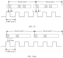
- FIG. 13(a) shows an example of choosing to use the first timer.
- the terminal device the transmit-side or receive-side terminal device
- the terminal device may use the reserved resource within the on duration. Therefore, the terminal device may choose to use the DRX inactivity timer with the first duration, in other words, choose to use the first timer corresponding to the first DRX mode.
- FIG. 13(b) shows an example of choosing to use the second timer.
- a reserved resource in the first period (namely, the first resource reservation period) is included in an on duration of the first DRX mode, but a reserved resource in the second period does not overlap the on duration of the first DRX mode.
- the terminal device is in an off duration, and cannot use the reserved resource in the second period.
- the terminal device uses the first timer, to be specific, uses a preconfigured timer with a fixed duration, the terminal device cannot make the reserved resource in the second period overlap the on duration of the first DRX mode.
- the terminal device may choose to use the second timer, in other words, autonomously determine a duration of a DRX inactivity timer. For example, if only the first resource in the second period needs to be included in the on duration of the first DRX mode, a duration of the second timer is required to be equal to a resource reservation period T plus a duration of the first resource in the second period. Certainly, if both the first resource and the second resource in the second period are required to be included in the on duration of the first DRX mode, a duration of the second timer is required to be equal to the resource reservation period T plus a duration between a start moment of the first resource in the second period and an end moment of the second resource in the second period.
- Embodiment 4 may be implemented in combination with Embodiment 1, Embodiment 2, or Embodiment 3.
- a terminal device is allowed to switch between configured DRX modes.
- the DRX mode configured for a sidelink may include a plurality of DRX modes.
- the DRX mode configured for a sidelink includes five DRX modes.
- the terminal device receives at least one DRX mode configured for a sidelink, where the at least one DRX mode configured for a sidelink includes a first DRX mode and a second DRX mode.
- the terminal device switches from the first DRX mode to the second DRX mode, or the terminal device stops the first DRX mode and starts, restarts, or enables the second DRX mode.
- the first DRX mode or the second DRX mode is not limited to one DRX mode, and may represent a plurality of DRX modes.
- the terminal device may switch to the second DRX mode, in other words, the second DRX mode is enabled (enabled).
- the terminal device determines that no SCI is detected within a third timer, and a duration corresponding to the third timer does not include a reserved time domain resource for a sidelink. That is, if the terminal device detects no SCI within the duration in which the third timer is on and the duration does not include a reserved time domain resource for a sidelink, the terminal device may switch from the first DRX mode to the second DRX mode.
- the duration of the third timer is a duration that is configured by a network device and that is used for the terminal device to determine whether to remain in the first DRX mode.
- an off duration of the second DRX mode is longer than that of the first DRX mode, thereby reducing power consumption of the terminal device.
- an active period of the first DRX mode includes an on duration of the first DRX mode and/or the duration corresponding to the third timer.
- FIG. 14 shows an example of switching between DRX modes.
- a DRX mode 1, a DRX mode 2, and a DRX mode 3 are preconfigured for the terminal device.
- the DRX mode 1 has a shortest off duration
- the DRX mode 3 has a longest off duration. For example, after the terminal device switches from the DRX mode 1 to the DRX mode 2, energy consumption of the terminal device can be reduced because an off duration is longer.
- the foregoing mainly describes the solutions provided in embodiments of this application from the perspective of interaction between network elements.
- the foregoing network elements include corresponding hardware structures and/or software modules for performing the functions.
- a person skilled in the art should easily be aware that, in combination with the units and algorithm steps in the examples described in embodiments disclosed in this specification, the application can be implemented by hardware or a combination of hardware and computer software. Whether a function is performed by hardware or hardware driven by computer software depends on a particular application and a design constraint of the technical solutions. A person skilled in the art may use different methods to implement the described functions for each particular application, but it should not be considered that the implementation goes beyond the scope of the application.
- the steps or operations correspondingly implemented by the terminal device in the foregoing method embodiments may alternatively be implemented by a component (for example, a chip or a circuit) configured on the terminal device.
- An embodiment of this application further provides an apparatus configured to implement any one of the foregoing methods, for example, provides an apparatus including units (or means) configured to implement the steps performed by the terminal device in any one of the foregoing methods.
- FIG. 15 is a schematic diagram of a communication apparatus according to an embodiment of this application.
- the apparatus is configured to implement steps performed by a corresponding terminal device (for example, the transmit-side terminal device or the receive-side terminal device) in the foregoing method embodiments.
- the apparatus 1500 includes an obtaining unit 1510 and a determining unit 1520.
- the apparatus 1500 further includes a sending unit 1530 and/or a receiving unit 1540.
- the obtaining unit 1510 is configured to obtain a time domain resource, where the time domain resource is used to transmit sidelink control information and/or sidelink data information.
- the determining unit 1520 is configured to determine a first discontinuous reception DRX mode based on the time domain resource, where the first DRX mode includes an on duration and an off duration, the time domain resource includes a first resource set or a second resource set, the first resource set includes N resources, the second resource set includes the periodic first resource set, and N is a positive integer.
- the determining unit 1520 is specifically configured to determine the first DRX mode based on a time domain location of the time domain resource, or determine the first DRX mode based on a status of overlapping between the time domain resource and an on duration of a candidate DRX mode, where the status of overlapping includes whether overlapping occurs and/or an overlapping degree.
- the candidate DRX mode includes a DRX mode configured for a sidelink resource pool, or includes a DRX mode configured for a sidelink.
- the time domain resource includes the first resource set, and at least one of the N resources in the first resource set is included in the on duration of the first DRX mode, or the first m symbols of at least one of the N resources in the first resource set overlap the on duration of the first DRX mode.
- the time domain resource includes the second resource set, and the first resource of N resources in a target period in the second resource set is included in the on duration of the first DRX mode, or the first m symbols of the first resource of N resources in a target period in the second resource set overlap the on duration of the first DRX mode, where the target period is at least one of the first Y periods corresponding to the second resource set, and Y is a positive integer.
- the communication apparatus is a receive-side terminal device
- the receiving unit 1540 is configured to receive indication information from a transmit-side terminal device or a network device, where the indication information is used to indicate a type of a DRX inactivity timer, and the type of the DRX inactivity timer is a first timer or a second timer.
- the first timer is a DRX inactivity timer with a configured duration
- the second timer is a DRX inactivity timer with a variable duration
- the first timer is a DRX inactivity timer with a first duration
- the second timer is a DRX inactivity timer with a second duration
- the first duration is configured by the network device or the transmit-side terminal device
- the second duration is determined by the transmit-end terminal device or the receive-end terminal device.
- the second duration is associated with the time domain of the time domain resource or a duration occupied by the time domain resource.
- the communication apparatus is a transmit-side terminal device
- the sending unit 1530 is configured to send indication information to a receive-side terminal device, where the indication information is used to indicate a type of a DRX inactivity timer, and the type of the DRX inactivity timer is a first timer or a second timer.
- the first timer is a DRX inactivity timer with a configured duration
- the second timer is a DRX inactivity timer with a variable duration
- the first timer is a DRX inactivity timer with a first duration
- the second timer is a DRX inactivity timer with a second duration
- the first duration is configured by a network device or the transmit-side terminal device
- the second duration is determined by the transmit-end terminal device or the receive-end terminal device.
- the second duration is associated with the time location of the time domain resource or a duration occupied by the time domain resource.
- the communication apparatus is a receive-side terminal device or a transmit-side terminal device
- the determining unit 1520 is further configured to determine, based on a status of overlapping between the on duration of the first DRX mode and the time domain resource, to use a first timer or a second timer, where the status of overlapping includes whether overlapping occurs and/or an overlapping degree.
- the first timer is a DRX inactivity timer with a configured duration
- the second timer is a DRX inactivity timer with a variable duration
- the first timer is a DRX inactivity timer with a first duration
- the second timer is a DRX inactivity timer with a second duration
- the first duration is configured by a network device or the transmit-side terminal device
- the second duration is determined by the transmit-end terminal device or the receive-end terminal device.
- the second duration is associated with the time domain of the time domain resource or a duration occupied by the time domain resource.
- the communication apparatus is a transmit-side terminal device, and the obtaining unit 1510 is specifically configured to perform detection in a sidelink resource pool to obtain the time domain resource.
- the apparatus further includes the sending unit, configured to send sidelink control information to a receive-side terminal device, where the sidelink control information includes the time domain resource and indication information, and the indication information is used to indicate the first DRX mode.
- the time domain resource is a reserved time domain resource
- the N resources included in the first resource set are reserved transmission resources used for one transport block or different transport blocks
- the periodic first resource set included in the second resource set is reserved transmission resources used for different transport blocks.
- the obtaining unit 1510 is configured to perform detection in a sidelink resource pool to obtain a time domain resource, where the time domain resource is used to transmit sidelink control information and/or sidelink data information.
- the determining unit 1520 is configured to determine a first DRX mode based on the time domain resource, where the first DRX mode includes an on duration and an off duration.
- the sending unit 1530 is configured to send sidelink control information to a receive-side terminal device, where the sidelink control information includes the time domain resource and indication information, the indication information is used to indicate the first DRX mode, the time domain resource includes a first resource set or a second resource set, the first resource set includes N resources, the second resource set includes the periodic first resource set, and N is a positive integer.
- the receiving unit 1540 is configured to receive indication information from a transmit-side terminal device or a network device, where the indication information is used to indicate a type of a DRX inactivity timer, and the type of the DRX inactivity timer is a first timer or a second timer.
- the first timer is a DRX inactivity timer with a configured duration
- the second timer is a DRX inactivity timer with a variable duration
- the first timer is a DRX inactivity timer with a first duration
- the second timer is a DRX inactivity timer with a second duration
- the first duration is configured by the network device or the transmit-side terminal device
- the second duration is determined by the transmit-end terminal device or a receive-end terminal device.
- the second duration is associated with a time domain of a time domain resource or a duration occupied by the time domain resource.
- the sending unit 1530 is configured to send indication information to a receive-side terminal device, where the indication information is used to indicate a type of a DRX inactivity timer, and the type of the DRX inactivity timer is a first timer or a second timer.
- the first timer is a DRX inactivity timer with a configured duration
- the second timer is a DRX inactivity timer with a variable duration
- the first timer is a DRX inactivity timer with a first duration
- the second timer is a DRX inactivity timer with a second duration
- the first duration is configured by a network device or a transmit-side terminal device
- the second duration is determined by the transmit-end terminal device or the receive-end terminal device.
- the second duration is associated with a time domain of a time domain resource or a duration occupied by the time domain resource.
- the determining unit 1520 is configured to determine, based on a status of overlapping between an on duration of a first DRX mode and a time domain resource, to use a first timer or a second timer, where the status of overlapping includes whether overlapping occurs and/or an overlapping degree.
- the first timer is a DRX inactivity timer with a configured duration
- the second timer is a DRX inactivity timer with a variable duration
- the first timer is a DRX inactivity timer with a first duration
- the second timer is a DRX inactivity timer with a second duration
- the first duration is configured by a network device or a transmit-side terminal device
- the second duration is determined by the transmit-end terminal device or a receive-end terminal device.
- the second duration is associated with a time domain of the time domain resource or a duration occupied by the time domain resource.
- the receiving unit 1540 is configured to receive at least one DRX mode configured for a sidelink, where the at least one DRX mode configured for a sidelink includes a first DRX mode and a second DRX mode; and the determining unit 1520 is configured to switch from the first DRX mode to the second DRX mode, or the terminal device stops the first DRX mode and starts, restarts, or enables the second DRX mode.
- the determining unit 1520 is further configured to determine that no SCI is detected within a third timer, and a duration corresponding to the third timer does not include a reserved time domain resource for a sidelink.
- an active period of the first DRX mode includes an on duration (on duration) of the first DRX mode and/or the duration corresponding to the third timer.
- the duration of the third timer is a duration that is configured by a network device and that is used for the terminal device to determine whether to remain in the first DRX mode.
- an off duration of the second DRX mode is longer than that of the first DRX mode.
- the foregoing units may also be referred to as modules, circuits, or the like, and the foregoing units may be disposed independently, or some or all of the units may be integrated.
- the sending unit 1530 and the receiving unit 1540 may alternatively be implemented by a transceiver unit, in other words, the sending unit 1530 and the receiving unit 1540 may also be collectively referred to as a transceiver unit.
- the sending unit 1530, the receiving unit 1540, or the transceiver unit may also be referred to as a communication interface.
- the communication apparatus 1500 may further include a storage unit.
- the storage unit is configured to store data or instructions (which may also be referred to as code or a program).
- the foregoing units may interact with or be coupled to the storage unit, to implement a corresponding method or function.
- the obtaining unit 1510 and the determining unit 1520 may read the data or the instructions in the storage unit, so that the communication apparatus implements the methods in the foregoing embodiments.
- each unit may be an independently disposed processing element; or may be integrated into a chip of the apparatus for implementation; or may be stored in a memory in a form of a program, so that the program is invoked by a processing element of the apparatus to perform a function of the unit.
- the processing element herein may also be referred to as a processor, and may be an integrated circuit with a signal processing capability.
- the steps in the foregoing methods or the foregoing units may be implemented by an integrated logic circuit of hardware in a processing element, or may be implemented in a form of software invoked by a processing element.
- the units in any one of the foregoing apparatuses may be one or more integrated circuits configured to implement the foregoing methods, for example, one or more application-specific integrated circuits (Application Specific Integrated Circuit, ASIC), one or more microprocessors (digital signal processor, DSP), one or more field programmable gate arrays (Field Programmable Gate Array, FPGA), or a combination of at least two of these integrated circuit forms.
- ASIC Application Specific Integrated Circuit
- DSP digital signal processor
- FPGA Field Programmable Gate Array
- the units in the apparatus may be implemented in a form of a program scheduled by a processing element
- the processing element may be a general-purpose processor, for example, a central processing unit (Central Processing Unit, CPU), or another processor capable of invoking the program.
- the units may be integrated together and implemented in a form of a system-on-a-chip (system-on-a-chip, SOC).
- the foregoing unit used for receiving is an interface circuit of the apparatus, and is configured to receiving a signal from another apparatus.
- the receiving unit is an interface circuit used by the chip to receive a signal from another chip or apparatus.
- the foregoing unit used for sending is an interface circuit of the apparatus, and is configured to send a signal to another apparatus.
- the sending unit is an interface circuit used by the chip to send a signal to another chip or apparatus.
- FIG. 16 is a schematic diagram of a structure of a terminal device according to an embodiment of this application.
- the terminal device is configured to implement the operations performed by the terminal device (for example, the transmit-side terminal device or the receive-side terminal device) in the foregoing embodiments.
- the terminal device includes an antenna 1610, a radio frequency apparatus 1620, and a signal processing part 1630.
- the antenna 1610 is connected to the radio frequency apparatus 1620.
- the radio frequency apparatus 1620 receives, by using the antenna 1610, information sent by a network device or another terminal device; and sends, to the signal processing part 1630 for processing, the information sent by the network device or the another terminal device.
- the signal processing part 1630 processes information of the terminal device, and sends processed information to the radio frequency apparatus 1620; and the radio frequency apparatus 1620 processes the information of the terminal device, and sends processed information to the network device or the another terminal device by using the antenna 1610.
- the signal processing part 1630 is configured to process each communication protocol layer of data.
- the signal processing part 1630 may be a subsystem of the terminal device.
- the terminal device may further include other subsystems, for example, a central processing subsystem, configured to process an operating system and an application layer of the terminal device, and for another example, a peripheral subsystem, configured to implement connection to another device.
- the signal processing part 1630 may be a chip that is disposed separately.
- the foregoing apparatus may be located in the signal processing part 1630.
- the signal processing part 1630 may include one or more processing elements 1631, for example, a main control CPU and other integrated circuits, and include an interface circuit 1633.
- the signal processing part 1630 may further include a storage element 1632.
- the storage element 1632 is configured to store data and a program.
- a program used to perform the methods performed by the terminal device in the foregoing methods may or may not be stored in the storage element 1632.
- the program is stored in a memory outside the signal processing part 1630.
- the signal processing part 1630 loads the program to a cache for use.
- the interface circuit 1633 is configured to communicate with the apparatus.
- the foregoing apparatus may be located in the signal processing part 1630.
- the signal processing part 1630 may be implemented by a chip.
- the chip includes at least one processing element and an interface circuit.
- the processing element is configured to perform steps of any method performed by the terminal device.
- the interface circuit is configured to communicate with another apparatus.
- the units for implementing the steps in the foregoing methods may be implemented in a form of a program scheduled by a processing element.
- the apparatus includes a processing element and a storage element, and the processing element invokes a program stored in the storage element to perform the methods performed by the terminal device in the foregoing method embodiments.
- the storage element may be a storage element located in a same chip as that of the processing element, namely, an on-chip storage element.
- the program used to perform the methods performed by the terminal device in the foregoing methods may be in a storage element located on a different chip from that of the processing element, namely, an off-chip storage element.
- the processing element invokes or loads the program from the off-chip storage element to an on-chip storage element, to invoke and perform the methods performed by the terminal device in the foregoing method embodiments.
- the units, in the terminal device, for implementing the steps in the foregoing methods may be configured as one or more processing elements, and the processing element is disposed in the signal processing part 1630.
- the processing element herein may be an integrated circuit, for example, one or more ASICs, one or more DSPs, one or more FPGAs, or a combination of these integrated circuits.
- the integrated circuits may be integrated together to form a chip.
- the units for implementing the steps in the foregoing methods may be integrated together and implemented in a form of a system-on-a-chip (system-on-a-chip, SOC).
- SOC system-on-a-chip
- the SOC chip is configured to implement the foregoing methods.
- At least one processing element and storage element may be integrated into the chip, and the processing element invokes a program stored in the storage element to implement the foregoing method performed by the network device.
- at least one integrated circuit may be integrated into the chip, to implement the foregoing method performed by the network device.
- functions of some units may be implemented by invoking a program by the processing element, and functions of some units may be implemented by the integrated circuit.
- the foregoing apparatus may include at least one processing element and an interface circuit, where the at least one processing element is configured to perform the method performed by any terminal device in the foregoing method embodiments.
- the processing element may perform some or all steps performed by the network device in a first manner, to be specific, by invoking the program stored in the storage element; or may perform some or all steps performed by the network device in a second manner, to be specific, by using a hardware integrated logic circuit in the processing element in combination with instructions; or may certainly perform, by combining the first manner and the second manner, some or all steps performed by the network device.
- the processing element herein may be a general-purpose processor, for example, a CPU, or may be one or more integrated circuits, for example, one or more ASICs, one or more microprocessors DSPs, one or more FPGAs, or a combination of at least two of these types of integrated circuits, configured to implement the foregoing method.
- the storage element may be one memory, or may be a general term of a plurality of storage elements.
- At least one item (piece) of a, b, and c may indicate: a, b, c, a and b, a and c, b and c, or a, b, and c, where a, b, and c may be singular or plural.
- "Plurality" means two or more, and other quantifiers are similar.
- sequence numbers of the foregoing processes do not mean execution sequences in various embodiments of this application.
- the execution sequences of the processes should be determined according to functions and internal logic of the processes, but should not be construed as any limitation on the implementation processes of embodiments of the application.
- the disclosed system, apparatus, and method may be implemented in another manner.
- the described apparatus embodiments are merely examples.
- division into the units is merely logical function division, or may be other division in actual implementation.
- a plurality of units or components may be combined or integrated into another system, or some features may be ignored or not performed.
- the displayed or discussed mutual couplings or direct couplings or communication connections may be implemented through some interfaces.
- the indirect couplings or communication connections between the apparatuses or units may be implemented in electrical, mechanical, or another form.
- the units described as separate parts may or may not be physically separate, and parts displayed as units may or may not be physical units, may be located in one position, or may be distributed on a plurality of network units. Some or all of the units may be selected based on actual requirements to achieve the objectives of the solutions of embodiments.
- All or some of the foregoing embodiments may be implemented by using software, hardware, firmware, or any combination thereof.
- software is used to implement embodiments, all or some of embodiments may be implemented in a form of a computer program product.
- the computer program product includes one or more computer instructions. When the computer program instructions are loaded and executed on the computer, the procedures or functions according to embodiments of this application are all or partially generated.
- the computer may be a general-purpose computer, a dedicated computer, a computer network, or another programmable apparatus.
- the computer instructions may be stored in a computer-readable storage medium, or may be transmitted from a computer-readable storage medium to another computer-readable storage medium.
- the computer instructions may be transmitted from a website, computer, server, or data center to another website, computer, server, or data center in a wired (for example, a coaxial cable, an optical fiber, or a digital subscriber line (DSL)) or wireless (for example, infrared, radio, or microwave) manner.
- the computer-readable storage medium may be any usable medium accessible by a computer, or a data storage device, such as a server or a data center, integrating one or more usable media.
- the usable medium may be a magnetic medium (for example, a floppy disk, a hard disk, or a magnetic tape), an optical medium (for example, a DVD), a semiconductor medium (for example, a solid-state disk (solid-state disk, SSD)), or the like.
- a magnetic medium for example, a floppy disk, a hard disk, or a magnetic tape
- an optical medium for example, a DVD
- a semiconductor medium for example, a solid-state disk (solid-state disk, SSD)
- the various illustrative logical units and circuits described in embodiments of this application may implement or operate the described functions by using a general-purpose processor, a digital signal processor, an application-specific integrated circuit (ASIC), a field programmable gate array (FPGA) or another programmable logical apparatus, a discrete gate or transistor logic, a discrete hardware component, or a design of any combination thereof.
- the general-purpose processor may be a microprocessor.
- the general-purpose processor may alternatively be any conventional processor, controller, microcontroller, or state machine.
- the processor may alternatively be implemented by a combination of computing apparatuses, such as a digital signal processor and a microprocessor, a plurality of microprocessors, one or more microprocessors in combination with a digital signal processor core, or any other similar configuration.
- Steps of the methods or algorithms described in embodiments of this application may be directly embedded into hardware, a software unit executed by a processor, or a combination thereof.
- the software unit may be stored in a random access memory (Random Access Memory, RAM), a flash memory, a read-only memory (Read-Only Memory, ROM), an EPROM memory, an EEPROM memory, a register, a hard disk, a removable hard disk, a CD-ROM, or any other form of storage medium in the art.
- the storage medium may connect to a processor, so that the processor can read information from the storage medium and write information into the storage medium.
- the storage medium may alternatively be integrated into the processor.
- the processor and the storage medium may be disposed in an ASIC.
- These computer program instructions may also be loaded onto a computer or another programmable data processing device, so that a series of operations and steps are performed on the computer or the another programmable device, thereby generating computer-implemented processing. Therefore, the instructions executed on the computer or the another programmable device provide steps for implementing a specific function in one or more processes in the flowcharts and/or in one or more blocks in the block diagrams.
- the computer-readable medium includes a computer storage medium and a communication medium.
- the communication medium includes any medium that facilitates transmission of a computer program from one place to another.
- the storage medium may be any available medium accessible to a general-purpose or a special-purpose computer.
Landscapes
- Engineering & Computer Science (AREA)
- Computer Networks & Wireless Communication (AREA)
- Signal Processing (AREA)
- Quality & Reliability (AREA)
- Mobile Radio Communication Systems (AREA)
Claims (13)
- Verfahren zum Bestimmen eines DRX-Modus, umfassend:Erlangen (401), durch ein Endgerät, einer Zeitdomänenressource, wobei die Zeitdomänenressource dazu verwendet wird, Sidelink-Steuerungsinformationen und/oder Sidelink-Dateninformationen zu übertragen; wobei das Endgerät ein empfangsseitiges Endgerät ist; undBestimmen (402), durch das Endgerät, eines ersten Modus für diskontinuierlichen Empfang, DRX-Modus, basierend auf der Zeitdomänenressource, wobei der erste DRX-Modus eine Einschaltdauer und eine Ausschaltdauer umfasst; unddie Zeitdomänenressource einen ersten Ressourcensatz oder einen zweiten Ressourcensatz umfasst, der erste Ressourcensatz N Ressourcen umfasst, der zweite Ressourcensatz einen periodischen ersten Ressourcensatz umfasst und N eine positive Ganzzahl ist;dadurch gekennzeichnet, dass das Bestimmen, durch das Endgerät, eines ersten DRX-Modus basierend auf der Zeitdomänenressource Folgendes umfasst:Bestimmen, durch das Endgerät, des ersten DRX-Modus basierend auf einem Überlappungsstatus zwischen der Zeitdomänenressource und einer Einschaltdauer eines in Betracht kommenden DRX-Modus,wobei der Überlappungsstatus, ob eine Überlappung auftritt, und/oder einen Überlappungsgrad umfasst.
- Verfahren nach Anspruch 1, wobei der in Betracht kommende DRX-Modus einen DRX-Modus umfasst, der für einen Sidelink-Ressourcenpool konfiguriert ist, oder einen DRX-Modus umfasst, der für einen Sidelink konfiguriert ist.
- Verfahren nach einem der Ansprüche 1 bis 2, wobei die Zeitdomänenressource den ersten Ressourcensatz umfasst; und mindestens eine der N Ressourcen in dem ersten Ressourcensatz in der Einschaltdauer des ersten DRX-Modus umfasst ist oder sich erste m Symbole mindestens einer der N Ressourcen in dem ersten Ressourcensatz mit der Einschaltdauer des ersten DRX-Modus überlappen.
- Verfahren nach einem der Ansprüche 1 bis 2, wobei die Zeitdomänenressource den zweiten Ressourcensatz umfasst; undeine erste Ressource von N Ressourcen in einem Zielzeitraum in dem zweiten Ressourcensatz in der Einschaltdauer des ersten DRX-Modus umfasst ist odersich die ersten m Symbole der ersten Ressource von N Ressourcen in einem Zielzeitraum in dem zweiten Ressourcensatz mit der Einschaltdauer des ersten DRX-Modus überlappen, wobeider Zielzeitraum mindestens einer erster Y Zeiträume ist, die dem zweiten Ressourcensatz entsprechen, und Y eine positive Ganzzahl ist.
- Verfahren nach einem der Ansprüche 1 bis 4, wobei das Endgerät ein empfangsseitiges Endgerät ist; und
das Verfahren ferner Folgendes umfasst:Empfangen, durch das empfangsseitige Endgerät, von Angabeinformationen von einem übertragungsseitigen Endgerät oder einem Netzgerät, wobei die Angabeinformationen dazu verwendet werden, einen Typus eines DRX-Inaktivitätstimers anzugeben, und der Typus des DRX-Inaktivitätstimers ein erster Timer oder ein zweiter Timer ist; undder erste Timer ein DRX-Inaktivitätstimer mit einer konfigurierten Dauer ist und der zweite Timer ein DRX-Inaktivitätstimer mit einer variablen Dauer ist; oderder erste Timer ein DRX-Inaktivitätstimer mit einer ersten Dauer ist und der zweite Timer ein DRX-Inaktivitätstimer mit einer zweiten Dauer ist, wobei die erste Dauer durch das Netzgerät oder das übertragungsseitige Endgerät konfiguriert ist und die zweite Dauer durch das übertragungsseitige Endgerät oder das empfangsseitige Endgerät bestimmt ist. - Verfahren nach einem der Ansprüche 1 bis 4, wobei das Endgerät ein übertragungsseitiges Endgerät ist; und
das Verfahren ferner Folgendes umfasst:Senden, durch das übertragungsseitige Endgerät, von Angabeinformationen an ein empfangsseitiges Endgerät, wobei die Angabeinformationen dazu verwendet werden, einen Typus eines DRX-Inaktivitätstimers anzugeben, und der Typus des DRX-Inaktivitätstimers ein erster Timer oder ein zweiter Timer ist; undder erste Timer ein DRX-Inaktivitätstimer mit einer konfigurierten Dauer ist und der zweite Timer ein DRX-Inaktivitätstimer mit einer variablen Dauer ist; oderder erste Timer ein DRX-Inaktivitätstimer mit einer ersten Dauer ist und der zweite Timer ein DRX-Inaktivitätstimer mit einer zweiten Dauer ist, wobei die erste Dauer durch ein Netzgerät oder das übertragungsseitige Endgerät konfiguriert ist und die zweite Dauer durch das übertragungsseitige Endgerät oder das empfangsseitige Endgerät bestimmt ist. - Verfahren nach einem der Ansprüche 1 bis 4, wobei das Endgerät ein empfangsseitiges Endgerät oder ein übertragungsseitiges Endgerät ist; und
das Verfahren ferner Folgendes umfasst:Bestimmen, durch das Endgerät basierend auf dem Überlappungsstatus zwischen der Einschaltdauer des ersten DRX-Modus und der Zeitdomänenressource, den ersten Timer oder den zweiten Timer zu verwenden, wobei der Überlappungsstatus, ob eine Überlappung auftritt, und/oder einen Überlappungsgrad umfasst; undder erste Timer ein DRX-Inaktivitätstimer mit einer konfigurierten Dauer ist und der zweite Timer ein DRX-Inaktivitätstimer mit einer variablen Dauer ist; oderder erste Timer ein DRX-Inaktivitätstimer mit einer ersten Dauer ist und der zweite Timer ein DRX-Inaktivitätstimer mit einer zweiten Dauer ist, wobei die erste Dauer durch ein Netzgerät oder das übertragungsseitige Endgerät konfiguriert ist und die zweite Dauer durch das übertragungsseitige Endgerät oder das empfangsseitige Endgerät bestimmt ist. - Verfahren nach einem der Ansprüche 1 bis 4, wobei das Endgerät ein übertragungsseitiges Endgerät ist;
das Erlangen (401), durch ein Endgerät, einer Zeitdomänenressource Folgendes umfasst:Durchführen, durch das Endgerät, von Erfassung in einem Sidelink-Ressourcenpool, um die Zeitdomänenressource zu erlangen; unddas Verfahren ferner Folgendes umfasst:
Senden, durch das übertragungsseitige Endgerät, von Sidelink-Steuerungsinformationen an ein empfangsseitiges Endgerät, wobei die Sidelink-Steuerungsinformationen die Zeitdomänenressource und Angabeinformationen umfassen und die Angabeinformationen dazu verwendet werden, den ersten DRX-Modus anzugeben. - Verfahren nach einem der Ansprüche 1 bis 8, wobei die Zeitdomänenressource eine reservierte Zeitdomänenressource ist; die N Ressourcen, die in dem ersten Ressourcensatz umfasst sind, reservierte Übertragungsressourcen sind, die für einen Transportblock oder unterschiedliche Transportblöcke verwendet werden; und
der periodische erste Ressourcensatz, der in dem zweiten Ressourcensatz umfasst ist, reservierte Übertragungsressourcen darstellt, die für unterschiedliche Transportblöcke verwendet werden. - Computerlesbares Speichermedium, wobei das computerlesbare Speichermedium Anweisungen speichert und, wenn die Anweisungen auf einem Computer ausgeführt werden, es dem Computer ermöglicht wird, das Verfahren nach einem der Ansprüche 1 bis 9 durchzuführen.
- Kommunikationsvorrichtung (1500), umfassend einen Prozessor, wobei der Prozessor an einen Speicher gekoppelt ist, der Speicher dazu konfiguriert ist, ein Programm oder Anweisungen zu speichern, und, wenn das Programm oder die Anweisungen durch den Prozessor ausgeführt werden, es der Vorrichtung ermöglicht wird, das Verfahren nach einem der Ansprüche 1 bis 9 durchzuführen.
- Kommunikationsvorrichtung (1500) nach Anspruch 11, ferner umfassend eine Schnittstelle, wobeider Prozessor dazu konfiguriert ist, die Vorrichtung zu steuern, um das Verfahren nach einem der Ansprüche 1 bis 9 durchzuführen; undder Prozessor ferner dazu konfiguriert ist, die Schnittstelle zu steuern, um mit einer anderen Vorrichtung zu kommunizieren.
- Computerprogrammprodukt, wobei das Computerprogrammprodukt ein Computerprogramm umfasst und, wenn das Computerprogramm ausgeführt wird, das Verfahren nach einem der Ansprüche 1 bis 9 durchgeführt wird.
Applications Claiming Priority (2)
| Application Number | Priority Date | Filing Date | Title |
|---|---|---|---|
| CN202010290736.2A CN113543235B (zh) | 2020-04-14 | 2020-04-14 | Drx模式的确定方法及通信装置 |
| PCT/CN2021/086012 WO2021208801A1 (zh) | 2020-04-14 | 2021-04-08 | Drx模式的确定方法及通信装置 |
Publications (3)
| Publication Number | Publication Date |
|---|---|
| EP4132089A1 EP4132089A1 (de) | 2023-02-08 |
| EP4132089A4 EP4132089A4 (de) | 2023-09-20 |
| EP4132089B1 true EP4132089B1 (de) | 2025-01-01 |
Family
ID=78083648
Family Applications (1)
| Application Number | Title | Priority Date | Filing Date |
|---|---|---|---|
| EP21787615.0A Active EP4132089B1 (de) | 2020-04-14 | 2021-04-08 | Verfahren zur bestimmung des drx-modus und kommunikationsvorrichtung |
Country Status (4)
| Country | Link |
|---|---|
| US (1) | US12563634B2 (de) |
| EP (1) | EP4132089B1 (de) |
| CN (1) | CN113543235B (de) |
| WO (1) | WO2021208801A1 (de) |
Families Citing this family (8)
| Publication number | Priority date | Publication date | Assignee | Title |
|---|---|---|---|---|
| CN111835476B (zh) * | 2019-04-22 | 2022-12-06 | 华为技术有限公司 | 通信方法与装置 |
| CN113543235B (zh) * | 2020-04-14 | 2024-11-19 | 华为技术有限公司 | Drx模式的确定方法及通信装置 |
| KR20220011444A (ko) * | 2020-07-21 | 2022-01-28 | 삼성전자주식회사 | 무선 통신 시스템에서 사이드링크의 비연속적 수신을 지원하기 위한 방법 및 장치 |
| EP4280771A4 (de) * | 2021-01-12 | 2024-12-18 | LG Electronics, Inc. | Verfahren und vorrichtung für sldrx-timerbetrieb auf basis des ressourcenzuweisungsmodus-2-betriebs in nr v2x |
| CN115734293B (zh) * | 2021-08-27 | 2026-03-03 | 维沃移动通信有限公司 | 资源选择方法、装置及终端 |
| CN116266779B (zh) * | 2021-12-14 | 2025-12-09 | 展讯通信(上海)有限公司 | 通信方法、装置及设备 |
| CN116470998A (zh) * | 2022-01-11 | 2023-07-21 | 大唐移动通信设备有限公司 | 资源指示方法、资源确定方法、装置及终端 |
| CN119732125A (zh) * | 2022-12-26 | 2025-03-28 | Oppo广东移动通信有限公司 | 资源配置方法及装置 |
Family Cites Families (16)
| Publication number | Priority date | Publication date | Assignee | Title |
|---|---|---|---|---|
| US8488521B2 (en) * | 2008-03-14 | 2013-07-16 | Interdigital Patent Holdings, Inc. | Behavior for wireless transmit/receive unit and MAC control elements for LTE DRX operations |
| JP6634744B2 (ja) * | 2015-09-09 | 2020-01-22 | 株式会社リコー | 情報処理システム、情報処理装置、機器、情報処理方法、プログラム |
| CN107306423B (zh) * | 2016-04-25 | 2019-09-17 | 电信科学技术研究院 | 一种进行业务传输的方法和终端 |
| DE112017003646T5 (de) * | 2016-07-21 | 2019-04-04 | Samsung Electronics Co., Ltd. | SYSTEM UND VERFAHREN ZUM ERKENNEN VON BENUTZERGERÄTEN (UEs) ÜBER SIDE-LINK IN VORRICHTUNG-ZU-VORRICHTUNG (D2D) -KOMMUNIKATION |
| CN108307489A (zh) * | 2016-08-11 | 2018-07-20 | 中兴通讯股份有限公司 | 信息处理方法、装置、用户设备及基站 |
| WO2018064477A1 (en) * | 2016-09-30 | 2018-04-05 | Intel IP Corporation | Systems and methods for discontinuous reception in device-to-device communication |
| MX2020001526A (es) * | 2017-08-11 | 2020-03-20 | 5G Ip Holdings Llc | Dispositivos y metodos para recepcion discontinua en radio nueva. |
| CN117651335A (zh) * | 2017-09-30 | 2024-03-05 | 华为技术有限公司 | 信息传输方法和装置 |
| WO2020042783A1 (zh) * | 2018-08-31 | 2020-03-05 | 中国移动通信有限公司研究院 | 指示信令的传输、接收方法、装置、网络侧设备及终端 |
| CN112312589B (zh) * | 2019-08-01 | 2024-01-19 | 大唐移动通信设备有限公司 | 一种节能信号的传输方法、基站及终端设备 |
| EP4024966B1 (de) * | 2019-10-11 | 2024-12-04 | Lg Electronics Inc. | Verfahren zur übertragung von einem sidelink-signal in einem drahtloskommunikationssystem |
| WO2021146940A1 (en) * | 2020-01-21 | 2021-07-29 | Lenovo (Beijing) Limited | Method and apparatus for power saving on nr sidelink |
| CN113225847B (zh) * | 2020-01-21 | 2023-10-24 | 华硕电脑股份有限公司 | 考虑不连续接收操作处理装置间资源选择的方法和设备 |
| CN113543235B (zh) * | 2020-04-14 | 2024-11-19 | 华为技术有限公司 | Drx模式的确定方法及通信装置 |
| CN119835805A (zh) * | 2020-05-20 | 2025-04-15 | 华为技术有限公司 | 一种通信方法及装置 |
| WO2022149879A1 (ko) * | 2021-01-07 | 2022-07-14 | 현대자동차주식회사 | 사이드링크 통신에서 모드 2에 기초한 자원 선택을 위한 방법 및 장치 |
-
2020
- 2020-04-14 CN CN202010290736.2A patent/CN113543235B/zh active Active
-
2021
- 2021-04-08 EP EP21787615.0A patent/EP4132089B1/de active Active
- 2021-04-08 WO PCT/CN2021/086012 patent/WO2021208801A1/zh not_active Ceased
-
2022
- 2022-10-13 US US17/965,146 patent/US12563634B2/en active Active
Also Published As
| Publication number | Publication date |
|---|---|
| EP4132089A4 (de) | 2023-09-20 |
| US20230038791A1 (en) | 2023-02-09 |
| WO2021208801A1 (zh) | 2021-10-21 |
| EP4132089A1 (de) | 2023-02-08 |
| US12563634B2 (en) | 2026-02-24 |
| CN113543235A (zh) | 2021-10-22 |
| CN113543235B (zh) | 2024-11-19 |
Similar Documents
| Publication | Publication Date | Title |
|---|---|---|
| EP4132089B1 (de) | Verfahren zur bestimmung des drx-modus und kommunikationsvorrichtung | |
| JP7706517B2 (ja) | 監視方法およびデバイス | |
| US12574848B2 (en) | Method for controlling communication in DRX | |
| US9363847B2 (en) | Method and apparatus for providing for discontinuous reception via cells having different time division duplex subframe configurations | |
| CN111356216A (zh) | 一种通信方法及其相关设备 | |
| AU2017430818B2 (en) | Discontinuous reception method, terminal device and network device | |
| JP2022123038A (ja) | 間欠受信方法、端末装置及びネットワーク装置 | |
| JP2020522929A (ja) | 信号伝送方法、ネットワーク・デバイス、および端末デバイス | |
| EP3673687B1 (de) | Multi-rat-drahtloskommunikation | |
| CN114424629A (zh) | 一种唤醒信号的检测方法及装置 | |
| CN108377551B (zh) | Drx处理方法及装置 | |
| EP3537767B1 (de) | Stationszuordnungsverfahren und -vorrichtung | |
| US20230074206A1 (en) | Communication method, apparatus, and system | |
| JP7817266B2 (ja) | サーチスペースグループ切り替え方法と機器 | |
| WO2017118179A1 (zh) | 一种寻呼处理方法、装置和寻呼系统 | |
| US20250344152A1 (en) | Communication method, terminal device, and network device | |
| CN114258117A (zh) | 确定终端行为的方法、指示终端行为的方法及装置 | |
| WO2024012114A1 (zh) | 通信方法及通信装置 | |
| CN118785370A (zh) | 寻呼方法及通信设备 | |
| CN114846855A (zh) | 通信方法、设备和计算机可读介质 | |
| CN114208363A (zh) | 一种冲突解决方法及装置 | |
| CN111436095A (zh) | 一种通信方法及通信装置 | |
| WO2022028212A1 (zh) | 信息处理方法、装置及终端 | |
| CN117939590A (zh) | 一种唤醒信号的监测、发送方法、通信节点及存储介质 | |
| CN115988648A (zh) | 下行控制信息监听方法及通信装置 |
Legal Events
| Date | Code | Title | Description |
|---|---|---|---|
| STAA | Information on the status of an ep patent application or granted ep patent |
Free format text: STATUS: THE INTERNATIONAL PUBLICATION HAS BEEN MADE |
|
| PUAI | Public reference made under article 153(3) epc to a published international application that has entered the european phase |
Free format text: ORIGINAL CODE: 0009012 |
|
| STAA | Information on the status of an ep patent application or granted ep patent |
Free format text: STATUS: REQUEST FOR EXAMINATION WAS MADE |
|
| 17P | Request for examination filed |
Effective date: 20221025 |
|
| AK | Designated contracting states |
Kind code of ref document: A1 Designated state(s): AL AT BE BG CH CY CZ DE DK EE ES FI FR GB GR HR HU IE IS IT LI LT LU LV MC MK MT NL NO PL PT RO RS SE SI SK SM TR |
|
| DAV | Request for validation of the european patent (deleted) | ||
| DAX | Request for extension of the european patent (deleted) | ||
| A4 | Supplementary search report drawn up and despatched |
Effective date: 20230821 |
|
| RIC1 | Information provided on ipc code assigned before grant |
Ipc: H04W 76/28 20180101ALI20230814BHEP Ipc: H04W 72/04 20230101ALI20230814BHEP Ipc: H04W 28/26 20090101AFI20230814BHEP |
|
| REG | Reference to a national code |
Ref country code: DE Ref legal event code: R079 Free format text: PREVIOUS MAIN CLASS: H04W0028260000 Ipc: H04W0092200000 Ref country code: DE Ref legal event code: R079 Ref document number: 602021024328 Country of ref document: DE Free format text: PREVIOUS MAIN CLASS: H04W0028260000 Ipc: H04W0092200000 |
|
| GRAP | Despatch of communication of intention to grant a patent |
Free format text: ORIGINAL CODE: EPIDOSNIGR1 |
|
| STAA | Information on the status of an ep patent application or granted ep patent |
Free format text: STATUS: GRANT OF PATENT IS INTENDED |
|
| RIC1 | Information provided on ipc code assigned before grant |
Ipc: H04W 76/28 20180101ALI20240712BHEP Ipc: H04W 92/20 20090101AFI20240712BHEP |
|
| INTG | Intention to grant announced |
Effective date: 20240802 |
|
| GRAS | Grant fee paid |
Free format text: ORIGINAL CODE: EPIDOSNIGR3 |
|
| GRAA | (expected) grant |
Free format text: ORIGINAL CODE: 0009210 |
|
| STAA | Information on the status of an ep patent application or granted ep patent |
Free format text: STATUS: THE PATENT HAS BEEN GRANTED |
|
| AK | Designated contracting states |
Kind code of ref document: B1 Designated state(s): AL AT BE BG CH CY CZ DE DK EE ES FI FR GB GR HR HU IE IS IT LI LT LU LV MC MK MT NL NO PL PT RO RS SE SI SK SM TR |
|
| REG | Reference to a national code |
Ref country code: GB Ref legal event code: FG4D |
|
| REG | Reference to a national code |
Ref country code: CH Ref legal event code: EP |
|
| REG | Reference to a national code |
Ref country code: DE Ref legal event code: R096 Ref document number: 602021024328 Country of ref document: DE |
|
| REG | Reference to a national code |
Ref country code: IE Ref legal event code: FG4D |
|
| REG | Reference to a national code |
Ref country code: LT Ref legal event code: MG9D |
|
| REG | Reference to a national code |
Ref country code: NL Ref legal event code: MP Effective date: 20250101 |
|
| REG | Reference to a national code |
Ref country code: AT Ref legal event code: MK05 Ref document number: 1757638 Country of ref document: AT Kind code of ref document: T Effective date: 20250101 |
|
| PG25 | Lapsed in a contracting state [announced via postgrant information from national office to epo] |
Ref country code: NL Free format text: LAPSE BECAUSE OF FAILURE TO SUBMIT A TRANSLATION OF THE DESCRIPTION OR TO PAY THE FEE WITHIN THE PRESCRIBED TIME-LIMIT Effective date: 20250101 |
|
| PG25 | Lapsed in a contracting state [announced via postgrant information from national office to epo] |
Ref country code: FI Free format text: LAPSE BECAUSE OF FAILURE TO SUBMIT A TRANSLATION OF THE DESCRIPTION OR TO PAY THE FEE WITHIN THE PRESCRIBED TIME-LIMIT Effective date: 20250101 |
|
| PG25 | Lapsed in a contracting state [announced via postgrant information from national office to epo] |
Ref country code: PL Free format text: LAPSE BECAUSE OF FAILURE TO SUBMIT A TRANSLATION OF THE DESCRIPTION OR TO PAY THE FEE WITHIN THE PRESCRIBED TIME-LIMIT Effective date: 20250101 |
|
| PGFP | Annual fee paid to national office [announced via postgrant information from national office to epo] |
Ref country code: DE Payment date: 20250305 Year of fee payment: 5 |
|
| PG25 | Lapsed in a contracting state [announced via postgrant information from national office to epo] |
Ref country code: ES Free format text: LAPSE BECAUSE OF FAILURE TO SUBMIT A TRANSLATION OF THE DESCRIPTION OR TO PAY THE FEE WITHIN THE PRESCRIBED TIME-LIMIT Effective date: 20250101 |
|
| PG25 | Lapsed in a contracting state [announced via postgrant information from national office to epo] |
Ref country code: NO Free format text: LAPSE BECAUSE OF FAILURE TO SUBMIT A TRANSLATION OF THE DESCRIPTION OR TO PAY THE FEE WITHIN THE PRESCRIBED TIME-LIMIT Effective date: 20250401 Ref country code: IS Free format text: LAPSE BECAUSE OF FAILURE TO SUBMIT A TRANSLATION OF THE DESCRIPTION OR TO PAY THE FEE WITHIN THE PRESCRIBED TIME-LIMIT Effective date: 20250501 |
|
| PG25 | Lapsed in a contracting state [announced via postgrant information from national office to epo] |
Ref country code: HR Free format text: LAPSE BECAUSE OF FAILURE TO SUBMIT A TRANSLATION OF THE DESCRIPTION OR TO PAY THE FEE WITHIN THE PRESCRIBED TIME-LIMIT Effective date: 20250101 |
|
| PG25 | Lapsed in a contracting state [announced via postgrant information from national office to epo] |
Ref country code: LV Free format text: LAPSE BECAUSE OF FAILURE TO SUBMIT A TRANSLATION OF THE DESCRIPTION OR TO PAY THE FEE WITHIN THE PRESCRIBED TIME-LIMIT Effective date: 20250101 Ref country code: PT Free format text: LAPSE BECAUSE OF FAILURE TO SUBMIT A TRANSLATION OF THE DESCRIPTION OR TO PAY THE FEE WITHIN THE PRESCRIBED TIME-LIMIT Effective date: 20250502 |
|
| PG25 | Lapsed in a contracting state [announced via postgrant information from national office to epo] |
Ref country code: BG Free format text: LAPSE BECAUSE OF FAILURE TO SUBMIT A TRANSLATION OF THE DESCRIPTION OR TO PAY THE FEE WITHIN THE PRESCRIBED TIME-LIMIT Effective date: 20250101 Ref country code: GR Free format text: LAPSE BECAUSE OF FAILURE TO SUBMIT A TRANSLATION OF THE DESCRIPTION OR TO PAY THE FEE WITHIN THE PRESCRIBED TIME-LIMIT Effective date: 20250402 |
|
| PG25 | Lapsed in a contracting state [announced via postgrant information from national office to epo] |
Ref country code: AT Free format text: LAPSE BECAUSE OF FAILURE TO SUBMIT A TRANSLATION OF THE DESCRIPTION OR TO PAY THE FEE WITHIN THE PRESCRIBED TIME-LIMIT Effective date: 20250101 |
|
| PG25 | Lapsed in a contracting state [announced via postgrant information from national office to epo] |
Ref country code: CZ Free format text: LAPSE BECAUSE OF FAILURE TO SUBMIT A TRANSLATION OF THE DESCRIPTION OR TO PAY THE FEE WITHIN THE PRESCRIBED TIME-LIMIT Effective date: 20250101 |
|
| PG25 | Lapsed in a contracting state [announced via postgrant information from national office to epo] |
Ref country code: SE Free format text: LAPSE BECAUSE OF FAILURE TO SUBMIT A TRANSLATION OF THE DESCRIPTION OR TO PAY THE FEE WITHIN THE PRESCRIBED TIME-LIMIT Effective date: 20250101 |
|
| REG | Reference to a national code |
Ref country code: DE Ref legal event code: R097 Ref document number: 602021024328 Country of ref document: DE |
|
| PG25 | Lapsed in a contracting state [announced via postgrant information from national office to epo] |
Ref country code: SM Free format text: LAPSE BECAUSE OF FAILURE TO SUBMIT A TRANSLATION OF THE DESCRIPTION OR TO PAY THE FEE WITHIN THE PRESCRIBED TIME-LIMIT Effective date: 20250101 |
|
| PG25 | Lapsed in a contracting state [announced via postgrant information from national office to epo] |
Ref country code: DK Free format text: LAPSE BECAUSE OF FAILURE TO SUBMIT A TRANSLATION OF THE DESCRIPTION OR TO PAY THE FEE WITHIN THE PRESCRIBED TIME-LIMIT Effective date: 20250101 |
|
| PG25 | Lapsed in a contracting state [announced via postgrant information from national office to epo] |
Ref country code: IT Free format text: LAPSE BECAUSE OF FAILURE TO SUBMIT A TRANSLATION OF THE DESCRIPTION OR TO PAY THE FEE WITHIN THE PRESCRIBED TIME-LIMIT Effective date: 20250101 |
|
| PG25 | Lapsed in a contracting state [announced via postgrant information from national office to epo] |
Ref country code: EE Free format text: LAPSE BECAUSE OF FAILURE TO SUBMIT A TRANSLATION OF THE DESCRIPTION OR TO PAY THE FEE WITHIN THE PRESCRIBED TIME-LIMIT Effective date: 20250101 |
|
| PG25 | Lapsed in a contracting state [announced via postgrant information from national office to epo] |
Ref country code: RO Free format text: LAPSE BECAUSE OF FAILURE TO SUBMIT A TRANSLATION OF THE DESCRIPTION OR TO PAY THE FEE WITHIN THE PRESCRIBED TIME-LIMIT Effective date: 20250101 |
|
| PG25 | Lapsed in a contracting state [announced via postgrant information from national office to epo] |
Ref country code: SK Free format text: LAPSE BECAUSE OF FAILURE TO SUBMIT A TRANSLATION OF THE DESCRIPTION OR TO PAY THE FEE WITHIN THE PRESCRIBED TIME-LIMIT Effective date: 20250101 |
|
| PLBE | No opposition filed within time limit |
Free format text: ORIGINAL CODE: 0009261 |
|
| STAA | Information on the status of an ep patent application or granted ep patent |
Free format text: STATUS: NO OPPOSITION FILED WITHIN TIME LIMIT |
|
| REG | Reference to a national code |
Ref country code: CH Ref legal event code: L10 Free format text: ST27 STATUS EVENT CODE: U-0-0-L10-L00 (AS PROVIDED BY THE NATIONAL OFFICE) Effective date: 20251112 |
|
| REG | Reference to a national code |
Ref country code: CH Ref legal event code: H13 Free format text: ST27 STATUS EVENT CODE: U-0-0-H10-H13 (AS PROVIDED BY THE NATIONAL OFFICE) Effective date: 20251125 |
|
| 26N | No opposition filed |
Effective date: 20251002 |
|
| PG25 | Lapsed in a contracting state [announced via postgrant information from national office to epo] |
Ref country code: LU Free format text: LAPSE BECAUSE OF NON-PAYMENT OF DUE FEES Effective date: 20250408 |
|
| PG25 | Lapsed in a contracting state [announced via postgrant information from national office to epo] |
Ref country code: MC Free format text: LAPSE BECAUSE OF FAILURE TO SUBMIT A TRANSLATION OF THE DESCRIPTION OR TO PAY THE FEE WITHIN THE PRESCRIBED TIME-LIMIT Effective date: 20250101 |
|
| REG | Reference to a national code |
Ref country code: BE Ref legal event code: MM Effective date: 20250430 |
|
| PG25 | Lapsed in a contracting state [announced via postgrant information from national office to epo] |
Ref country code: FR Free format text: LAPSE BECAUSE OF NON-PAYMENT OF DUE FEES Effective date: 20250430 |
|
| PG25 | Lapsed in a contracting state [announced via postgrant information from national office to epo] |
Ref country code: BE Free format text: LAPSE BECAUSE OF NON-PAYMENT OF DUE FEES Effective date: 20250430 |
|
| PG25 | Lapsed in a contracting state [announced via postgrant information from national office to epo] |
Ref country code: CH Free format text: LAPSE BECAUSE OF NON-PAYMENT OF DUE FEES Effective date: 20250430 |
|
| PGFP | Annual fee paid to national office [announced via postgrant information from national office to epo] |
Ref country code: GB Payment date: 20260310 Year of fee payment: 6 |
|
| PG25 | Lapsed in a contracting state [announced via postgrant information from national office to epo] |
Ref country code: IE Free format text: LAPSE BECAUSE OF NON-PAYMENT OF DUE FEES Effective date: 20250408 |