EP4131945A1 - Image processing device, vehicle, image processing method, and program - Google Patents
Image processing device, vehicle, image processing method, and program Download PDFInfo
- Publication number
- EP4131945A1 EP4131945A1 EP20929198.8A EP20929198A EP4131945A1 EP 4131945 A1 EP4131945 A1 EP 4131945A1 EP 20929198 A EP20929198 A EP 20929198A EP 4131945 A1 EP4131945 A1 EP 4131945A1
- Authority
- EP
- European Patent Office
- Prior art keywords
- vehicle
- image
- image processing
- processing device
- driver
- Prior art date
- Legal status (The legal status is an assumption and is not a legal conclusion. Google has not performed a legal analysis and makes no representation as to the accuracy of the status listed.)
- Granted
Links
Images


Classifications
-
- B—PERFORMING OPERATIONS; TRANSPORTING
- B60—VEHICLES IN GENERAL
- B60R—VEHICLES, VEHICLE FITTINGS, OR VEHICLE PARTS, NOT OTHERWISE PROVIDED FOR
- B60R1/00—Optical viewing arrangements; Real-time viewing arrangements for drivers or passengers using optical image capturing systems, e.g. cameras or video systems specially adapted for use in or on vehicles
- B60R1/20—Real-time viewing arrangements for drivers or passengers using optical image capturing systems, e.g. cameras or video systems specially adapted for use in or on vehicles
-
- H—ELECTRICITY
- H04—ELECTRIC COMMUNICATION TECHNIQUE
- H04N—PICTORIAL COMMUNICATION, e.g. TELEVISION
- H04N7/00—Television systems
- H04N7/18—Closed-circuit television [CCTV] systems, i.e. systems in which the video signal is not broadcast
- H04N7/181—Closed-circuit television [CCTV] systems, i.e. systems in which the video signal is not broadcast for receiving images from a plurality of remote sources
-
- B—PERFORMING OPERATIONS; TRANSPORTING
- B60—VEHICLES IN GENERAL
- B60R—VEHICLES, VEHICLE FITTINGS, OR VEHICLE PARTS, NOT OTHERWISE PROVIDED FOR
- B60R1/00—Optical viewing arrangements; Real-time viewing arrangements for drivers or passengers using optical image capturing systems, e.g. cameras or video systems specially adapted for use in or on vehicles
- B60R1/20—Real-time viewing arrangements for drivers or passengers using optical image capturing systems, e.g. cameras or video systems specially adapted for use in or on vehicles
- B60R1/22—Real-time viewing arrangements for drivers or passengers using optical image capturing systems, e.g. cameras or video systems specially adapted for use in or on vehicles for viewing an area outside the vehicle, e.g. the exterior of the vehicle
- B60R1/23—Real-time viewing arrangements for drivers or passengers using optical image capturing systems, e.g. cameras or video systems specially adapted for use in or on vehicles for viewing an area outside the vehicle, e.g. the exterior of the vehicle with a predetermined field of view
- B60R1/27—Real-time viewing arrangements for drivers or passengers using optical image capturing systems, e.g. cameras or video systems specially adapted for use in or on vehicles for viewing an area outside the vehicle, e.g. the exterior of the vehicle with a predetermined field of view providing all-round vision, e.g. using omnidirectional cameras
-
- B—PERFORMING OPERATIONS; TRANSPORTING
- B60—VEHICLES IN GENERAL
- B60R—VEHICLES, VEHICLE FITTINGS, OR VEHICLE PARTS, NOT OTHERWISE PROVIDED FOR
- B60R1/00—Optical viewing arrangements; Real-time viewing arrangements for drivers or passengers using optical image capturing systems, e.g. cameras or video systems specially adapted for use in or on vehicles
- B60R1/20—Real-time viewing arrangements for drivers or passengers using optical image capturing systems, e.g. cameras or video systems specially adapted for use in or on vehicles
- B60R1/29—Real-time viewing arrangements for drivers or passengers using optical image capturing systems, e.g. cameras or video systems specially adapted for use in or on vehicles for viewing an area inside the vehicle, e.g. for viewing passengers or cargo
-
- B—PERFORMING OPERATIONS; TRANSPORTING
- B62—LAND VEHICLES FOR TRAVELLING OTHERWISE THAN ON RAILS
- B62H—CYCLE STANDS; SUPPORTS OR HOLDERS FOR PARKING OR STORING CYCLES; APPLIANCES PREVENTING OR INDICATING UNAUTHORIZED USE OR THEFT OF CYCLES; LOCKS INTEGRAL WITH CYCLES; DEVICES FOR LEARNING TO RIDE CYCLES
- B62H5/00—Appliances preventing or indicating unauthorised use or theft of cycles; Locks integral with cycles
-
- B—PERFORMING OPERATIONS; TRANSPORTING
- B62—LAND VEHICLES FOR TRAVELLING OTHERWISE THAN ON RAILS
- B62J—CYCLE SADDLES OR SEATS; AUXILIARY DEVICES OR ACCESSORIES SPECIALLY ADAPTED TO CYCLES AND NOT OTHERWISE PROVIDED FOR, e.g. ARTICLE CARRIERS OR CYCLE PROTECTORS
- B62J50/00—Arrangements specially adapted for use on cycles not provided for in main groups B62J1/00 - B62J45/00
- B62J50/20—Information-providing devices
- B62J50/21—Information-providing devices intended to provide information to rider or passenger
- B62J50/22—Information-providing devices intended to provide information to rider or passenger electronic, e.g. displays
-
- G—PHYSICS
- G06—COMPUTING OR CALCULATING; COUNTING
- G06T—IMAGE DATA PROCESSING OR GENERATION, IN GENERAL
- G06T3/00—Geometric image transformations in the plane of the image
- G06T3/40—Scaling of whole images or parts thereof, e.g. expanding or contracting
- G06T3/4038—Image mosaicing, e.g. composing plane images from plane sub-images
-
- H—ELECTRICITY
- H04—ELECTRIC COMMUNICATION TECHNIQUE
- H04N—PICTORIAL COMMUNICATION, e.g. TELEVISION
- H04N23/00—Cameras or camera modules comprising electronic image sensors; Control thereof
- H04N23/90—Arrangement of cameras or camera modules, e.g. multiple cameras in TV studios or sports stadiums
-
- H—ELECTRICITY
- H04—ELECTRIC COMMUNICATION TECHNIQUE
- H04N—PICTORIAL COMMUNICATION, e.g. TELEVISION
- H04N5/00—Details of television systems
- H04N5/222—Studio circuitry; Studio devices; Studio equipment
- H04N5/262—Studio circuits, e.g. for mixing, switching-over, change of character of image, other special effects ; Cameras specially adapted for the electronic generation of special effects
- H04N5/2628—Alteration of picture size, shape, position or orientation, e.g. zooming, rotation, rolling, perspective, translation
-
- H—ELECTRICITY
- H04—ELECTRIC COMMUNICATION TECHNIQUE
- H04N—PICTORIAL COMMUNICATION, e.g. TELEVISION
- H04N5/00—Details of television systems
- H04N5/222—Studio circuitry; Studio devices; Studio equipment
- H04N5/262—Studio circuits, e.g. for mixing, switching-over, change of character of image, other special effects ; Cameras specially adapted for the electronic generation of special effects
- H04N5/265—Mixing
Definitions
- the present invention mainly relates to an image processing device.
- Patent Literature 1 describes an image processing technology for providing a virtual viewpoint in an image showing a state of a vehicle and the surroundings of the vehicle, and causing the image to be visually recognized while changing the virtual viewpoint.
- Patent Literature 1 discloses theft prevention as a usage example of such a technology.
- An exemplary objective of the present invention is to make it possible to relatively easily realize diversification of applications of images obtained through the above-described image processing technology.
- a first aspect of the present invention is an image processing device processing an image of a vehicle, the image processing device characterized by comprising first acquisition means for acquiring an image showing a situation around the vehicle as a vehicle surrounding image, second acquisition means for acquiring information indicating a state of the vehicle, third acquisition means for acquiring an image of a driver of the vehicle as a driver image, and image generation means for generating an image of the vehicle as a vehicle image based on the information acquired by the second acquisition means and generating a composite image by superimposing the vehicle image and the driver image on the vehicle surrounding image.
- the present invention is advantageous for diversification of applications of images obtained by the above-described image processing technology.
- FIG. 1 is a schematic diagram illustrating an exemplary configuration of an image display system SY according to an embodiment.
- the image display system SY includes a vehicle 1, an image processing device 2, and a terminal 3 which are assumed to be able to communicate with each other via a network N in the present embodiment.
- the vehicle 1 is a straddled vehicle in the present embodiment.
- a straddle type vehicle is a type of vehicle that a driver boards by straddling a vehicle body, and the concept of the straddle type vehicle includes not only a typical motorcycle (including a scooter type vehicle) but also, for example, an all-terrain vehicle (ATV) such as a three-wheeled vehicle (a vehicle with one front wheel and two rear wheels or a vehicle with two front wheels and one rear wheel) and a four-wheeled buggy.
- the vehicle 1 may be a passenger vehicle.
- the vehicle 1 includes imaging devices 11A, imaging devices 11B, a detection device 12, and a communication device 13.
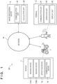
- FIG. 2 is a schematic diagram illustrating an exemplary functional configuration of the vehicle 1.
- the plurality of imaging devices 11A are provided in the surroundings of the vehicle body to be able to capture an image showing a state of the surroundings of the vehicle 1.
- the plurality of imaging devices 11A are provided so that imaging areas of the imaging devices 11A include the entire surroundings of the vehicle 1. That is, the plurality of imaging devices 11A are provided such that imaging areas of two imaging devices 11A adj acent to each other partially overlap each other.
- an orientation direction of the imaging devices 11A is schematically illustrated by a dotted line, but an actual detection range of the imaging devices 11A is wider than a range illustrated in the drawing.
- the imaging devices 11B are provided both in front of and behind the driver's seat to be able to image the driver from each of the front and the rear.
- the orientation direction of the imaging devices 11B is schematically illustrated by a dotted line, but the actual detection range of the imaging devices 11B is wider than the range illustrated in the drawing. Accordingly, as will be described below in detail, an appearance, an attitude, a behavior, and the like of the driver can be imaged.
- CMOS image sensor CMOS image sensor
- monocular cameras are used in order to reduce cost required for the imaging devices 11A and 11B.
- the detection device 12 is provided at each portion of the vehicle body to be able to detect a state of the vehicle 1.
- the state of the vehicle 1 includes a vehicle speed, a steering angle, an attitude of the vehicle body, and a state of the lamp body (a headlight, a taillight, a blinker, and the like).
- the vehicle speed is detected based on, for example, a revolution speed of a wheel per unit time, and this can be realized by using a known speed sensor.
- the steering angle is detected based on, for example, the direction of the steering wheel with respect to the vehicle body (alternatively, the direction of a handlebar with respect to the vehicle body), and this can be realized by using a known steering angle sensor.
- the attitude of the vehicle body is detected based on, for example, a direction of the vehicle body with respect to a direction of gravity, and this can be realized by using a known acceleration sensor.
- the state of the lamp body is detected based on, for example, a conduction state of the light source, and this can be realized by using a known ammeter.
- the communication device 13 transmits imaging results from the imaging devices 11A and 11B and a detection result from the detection device 12 to the image processing device 2 via the network N.
- the communication device 13 may be expressed as a transceiver device or the like or may be simply expressed as a transmission device in the present embodiment.
- the imaging result from the imaging devices 11A indicates an image (hereinafter referred to as a vehicle surrounding image 9A) indicating a state around the vehicle 1.
- the imaging result from the imaging devices 11B indicates an image of the driver (hereinafter referred to as a driver image 9B).
- the detection result from the detection device 12 indicates information (hereinafter referred to as vehicle information 9i) indicating the state of the vehicle 1.
- the image processing device 2 includes a communication unit 21 and a calculation unit 22.
- the communication unit 21 enables the image processing device 2 to communicate with each of the vehicle 1 and the terminal 3 via the network N.
- the calculation unit 22 performs predetermined calculation processing including image processing, as will described in detail below.
- the calculation unit 22 is a processor including a CPU and a memory, and a function of the calculation unit 22 is realized by executing a predetermined program. That is, the program may be read via a network or a storage medium and executed on a computer.
- the calculation unit 22 may be configured as a semiconductor device such as a programmable logic device (PLD) or an application specific semiconductor integrated circuit (ASIC). That is, the function of the calculation unit 22 can be realized by either hardware or software.
- PLD programmable logic device
- ASIC application specific semiconductor integrated circuit
- the terminal 3 is a mobile terminal (for example, a smartphone) and includes a communication unit 31, an operation unit 32, and a display unit 33.
- the user of the terminal 3 may be a driver of the vehicle 1 or a third party different from the driver.
- the communication unit 31 enables the terminal 3 to communicate with the image processing device 2 via the network N.
- the operation unit 32 can receive an operation input from the user and the display unit 33 can display an image.
- the operation unit 32 and the display unit 33 may be integrated (for example, a touch panel display may be used) or may be individually provided.
- the vehicle 1 can communicate with the image processing device 2 and transmit the imaging results from the imaging devices 11A and 11B and the detection result from the detection device 12 to the image processing device 2.
- the image processing device 2 performs predetermined image processing with the calculation unit 22 based on the imaging results and the detection result, generates a composite image (hereinafter referred to as a composite image 9X), and transmits the composite image 9X to the terminal 3.
- the user can visually recognize the composite image 9X on the display unit 33 while performing an operation input to the operation unit 32 on the terminal 3.
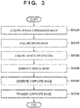
- FIG. 3 is a flowchart illustrating an example of an image processing method of generating the composite image 9X.
- Content of this flowchart is mainly performed by the calculation unit 22.
- An overview of the content is to generate an image (hereinafter referred to as a vehicle image 9C) of the vehicle 1 based on the vehicle information 9i and to generate the composite image 9X using the images 9A to 9C.
- the flowchart may be executed when the vehicle 1 is being used (during traveling), or may be executed after use of the vehicle 1 (during non-traveling).
- step S1000 the vehicle surrounding image 9A is acquired from the vehicle 1.
- the vehicle surrounding image 9A is obtained by the plurality of imaging devices 11A, and the plurality of imaging devices 11A are provided in the surrounding portions of the vehicle body such that the imaging area includes the entire area around the vehicle 1. Accordingly, the vehicle surrounding image 9A shows a situation of the entire area around the vehicle 1 and is obtained in a so-called panoramic view (360-degree panoramic view). Therefore, the image processing on the vehicle surrounding image 9A can be relatively easily performed by using a spherical coordinate system.
- the driver image 9B is acquired from the vehicle 1.
- the driver image 9B is obtained by the pair of imaging devices 11B provided in front of and behind the driver's seat, and the pair of imaging devices 11B is provided to be able to image the driver from the front and the rear.
- the driver image 9B indicates a driving mode of the driver, such as an appearance (for example, skeleton and cloth (a helmet is included in addition to wear)), an attitude (in the case of a still image), and a behavior (in the case of a moving image) of the driver.
- the image processing on the driver image 9B can be relatively easily performed by using a 3-dimensional coordinate system based on a predetermined human body model.
- the vehicle information 9i is acquired from the vehicle 1.
- the vehicle information 9i is obtained by the detection device 12 provided in each portion of the vehicle body to be able to detect a state of the vehicle 1.
- the state of the vehicle 1 includes a vehicle speed, a steering angle, an attitude of the vehicle body, and a state of the lamp body.
- the vehicle image 9C is generated based on the vehicle information 9i. Since the vehicle information 9i indicates the vehicle speed, the steering angle, the attitude of the vehicle body, and the state of the lamp body, an image of the vehicle 1 in a state corresponding thereto is generated as the vehicle image 9C. Accordingly, the image processing on the vehicle image 9C can be relatively easily performed by using the 3-dimensional coordinate system which is based on the corresponding vehicle model.
- the images 9B and 9C are superimposed on the vehicle surrounding image 9A to generate the composite image 9X.
- the vehicle surrounding image 9A is processed with the spherical coordinate system
- the driver image 9B and the vehicle image 9C are processed with the 3-dimensional coordinate system.
- the 3-dimensional coordinate system can be typically indicated by coordinates (x, y, z) using a distance x from a coordinate center to a target to in the front-and-rear direction of the vehicle body, a distance y from the coordinate center to the target in the left-and-right direction of the vehicle body, and a distance z from the coordinate center to the target in the up-and-down direction of the vehicle body.
- the spherical coordinate system can be typically indicated by coordinates (r, ⁇ , ⁇ ) using a distance r from the coordinate center to the target, an angle ⁇ formed by a line passing between the coordinate center and the target and the up-and-down direction of the vehicle body, and an angle ⁇ formed by a line passing between the coordinate center and the target and the front-and-rear direction of the vehicle body.
- FIG. 4A is a schematic diagram illustrating the vehicle surrounding image 9A.
- the vehicle surrounding image 9A is processed with the spherical coordinate system and drawn at a position at the distance r from the coordinate center.
- the vehicle surrounding image 9A which is a panoramic view is drawn on the inner wall of a sphere that has the radius r.
- the radius r may be set to be a position outside of the vehicle 1.
- FIG. 4B is a schematic diagram illustrating the driver image 9B.
- the driver image 9B is processed with a 3-dimensional coordinate system, and a head, a shoulder, a torso (chest and abdomen), a waist, an arm (upper arm and forearm), a hand, a leg (thigh and lower leg), a foot, and the like can be drawn based on a predetermined human body model, for example. Incidentally, clothing may be further depicted.
- FIG. 4C is a schematic diagram illustrating the vehicle image 9C.
- the vehicle image 9C is processed with a 3-dimensional coordinate system. For example, an image of the vehicle 1 in a state based on the vehicle information 9i (information indicating a vehicle speed, a steering angle, an attitude of the vehicle body, and a state of a light body) can be drawn. For example, for the vehicle 1 during cornering, the vehicle image 9C can be drawn in an attitude in which the vehicle body is inclined.
- the vehicle information 9i information indicating a vehicle speed, a steering angle, an attitude of the vehicle body, and a state of a light body
- the imaging results by the imaging devices 11A and 11B are preferably corrected according to the degree of inclination of the vehicle body. For example, in a case where the vehicle surrounding image 9A is acquired by the imaging device 11A when the attitude of the vehicle body is inclined at the inclination angle ⁇ 1, the image 9A can be rotated by the angle ⁇ 1.
- the correction processing on the imaging results by the imaging devices 11A and 11B may be performed in the image processing device 2 or may be performed in the vehicle 1.
- FIG. 4D is a schematic diagram illustrating the composite image 9X.
- the images 9A to 9C may be combined such that the coordinate center, the distance, and the direction coincide with each other.
- the coordinate center is a position immediately above the seat in the present embodiment, but may be another position (for example, any position of the vehicle body) as another embodiment.
- step S1050 the composite image 9X is transmitted to the terminal 3.
- the user of the terminal 3 can display the composite image 9X on the display unit 33 at a viewpoint (hereinafter referred to as a virtual viewpoint) from any position through an operation input to the operation unit 32.
- the user can zoom in or out of the composite image 9X through an operation input to the operation unit 32.
- FIG. 5A illustrates an example of the composite image 9X in the case of a touch panel type display in which the operation unit 32 and the display unit 33 are integrated.
- FIG. 5B illustrates another example of the composite image 9X (an example of the composite image 9X at a virtual viewpoint different from FIG. 5A ).
- icons 8a and 8b for changing the virtual viewpoint, an icon 8c for zooming in, and an icon 8d for zooming out are displayed as parts of the operation unit 32.
- a predetermined operation input for example, a tap operation, a swipe operation, a flick operation, or the like.
- the size of the vehicle image 9C in the composite image 9X is changed, and the size of the driver image 9B is also changed incidentally, and thus there is a case where discomfort of a change in the appearance of the composite image 9X with the change is reduced.
- the size of the vehicle surrounding image 9A in the composite image 9X may be maintained when the virtual viewpoint is changed.
- the vehicle surrounding image 9A can be clearly displayed by using the imaging device 11A that has a relatively large number of pixels.
- the images 9A to 9C are required to show states at substantially the same time. Accordingly, the images 9A to 9C can be associated with attribute information indicating time (a timing at which the image is captured or a timing at which information, based on which the image is generated, is acquired). Incidentally, the images 9A to 9C may be associated with attribute information indicating a location (a location in which the image is captured or a location at which information, based on which the image is generated, is acquired).
- the 3-dimensional coordinate system may typically be indicated by coordinates (x, y, z).
- the spherical coordinate system may typically be indicated by coordinates (r, ⁇ , ⁇ ). Therefore, as another embodiment, by using a known coordinate transformation, the driver image 9B and the vehicle image 9C may be processed with the spherical coordinate system similarly to the vehicle surrounding image 9A. Alternatively, the vehicle surrounding image 9A may be processed with a 3-dimensional coordinate system similarly to the driver image 9B and the vehicle image 9C.
- a monocular camera is used as the imaging device 111, but a multiocular camera can be alternatively used.
- a monocular camera is used as the imaging device 111, but a multiocular camera can be alternatively used.
- the vehicle surrounding image 9A can be processed with the 3-dimensional coordinate system relatively easily.
- the driver image 9B is used in generation of the composite image 9X.
- the driver image 9B need not be used when the vehicle 1 is a passenger vehicle (for example, when it is difficult to visually recognize the driver from the outside of the vehicle).
- the imaging device 11B may be omitted.
- the image indicating the situation around the vehicle 1 is acquired as the vehicle surrounding image 9A, and the vehicle information 9i indicating the state of the vehicle 1 is acquired. Thereafter, an image of the vehicle 1 is generated as the vehicle image 9C based on the vehicle information 9i.
- the vehicle image 9C is superimposed on the vehicle surrounding image 9A to generate a composite image 9X.
- the driver image 9B may be incidentally superimposed on the vehicle surrounding image 9A.
- the user for example, a driver
- the composite image 9X can be used for various applications and, as an example, can be used as a drive recorder indicating a more detailed driving situation.
- the functions of the image processing device 2 are realized in a location (for example, a server) different from the vehicle 1, and the display of the composite image 9 and the change in the virtual viewpoint are performed in the terminal 3.
- a location for example, a server
- the present invention is not limited to this mode.
- FIG. 6A illustrates an exemplary configuration of an image display system SYa.
- the image processing device 2 is mounted on the vehicle 1.
- the transmission of the composite image 9X from the vehicle 1 to the terminal 3 may be performed via the network N, or may be performed by known communication means (for example, Bluetooth (registered trademark)).
- FIG. 6B illustrates an exemplary configuration of an image display system SYb.
- the image processing device 2 is provided in the terminal 3. That is, the terminal 3 may receive the images 9A and 9B and the vehicle information 9i from the vehicle 1 via the network N or the like, generate the composite image 9X based on the images 9A and 9B and the vehicle information 9i, and display the composite image 9X on the display unit 33.
- the terminal 3 may be an in-vehicle monitor (For example, a car navigation system). In this case, the driver can visually recognize the surrounding situation from a desired virtual viewpoint while driving the vehicle 1.
- each element is indicated by a name related to its functional aspect, but each element is not limited to an element that has the content described in the embodiment as a main function, and may be element that has the content supplementarily.
- the vehicle 1 has been exemplified as a typical example.
- the content of the embodiment can be applied to objects not including wheels (vessels and the like), that is, to various movable bodies.
- a first aspect is an image processing device (2), processing an image of a vehicle (1), characterized by comprising first acquisition means (S1000) for acquiring an image showing a situation around the vehicle as a vehicle surrounding image (9A), second acquisition means (S1020) for acquiring information (9i) indicating a state of the vehicle, and image generation means (S1030, S1040) for generating an image of the vehicle as a vehicle image (9C) based on the information acquired by the second acquisition means and generating a composite image (9X) by superimposing the vehicle image and the driver image on the vehicle surrounding image.
- first acquisition means S1000
- second acquisition means for acquiring information (9i) indicating a state of the vehicle
- image generation means S1030, S1040
- the composite image obtained in this way can be utilized for various applications.
- the third acquisition means for example, S1010 for acquiring an image of a driver of the vehicle as a driver image (for example, 9B) is further included, and the image generation means generates the composite image by further superimposing the driver image on the vehicle surrounding image.
- the image generation means processes the vehicle surrounding image with a spherical coordinate system.
- the processing of the vehicle surrounding image can be relatively easily realized.
- the image generation means processes the vehicle image with a 3-dimensional coordinate system.
- the processing of the vehicle image can be relatively easily realized.
- the image processing device further comprises transmission means (S1050) for transmitting the composite image to a predetermined terminal (3), wherein a user of the terminal can display the composite image at a viewpoint from an arbitrary position by an operation input on the terminal.
- transmission means S1050
- the user can visually recognize the state of the vehicle and the surroundings of the vehicle from an arbitrary viewpoint.
- the image processing device further comprises display means (33, Fig.5A, Fig.5B ) for displaying the composite image at a viewpoint from an arbitrary position.
- the user can visually recognize the state of the vehicle and the surroundings of the vehicle from an arbitrary viewpoint.
- the display means changes a size of the vehicle image with a change in the viewpoint.
- the sixth aspect when the viewpoint is changed, it is possible to reduce discomfort of the change in the composite image accompanying the change in the viewpoint.
- the state of the vehicle includes a vehicle speed, a steering angle, an attitude of a vehicle body, and/or a state of a lamp body.
- An eighth aspect is a vehicle (1) capable of communicating with the above image processing device, the vehicle characterized by comprising a first imaging device (11A) configured to capture an image showing a situation around the vehicle, a detection device (12) configured to detect a state of the vehicle, and a communication device configured to transmit an imaging result from the first imaging device and a detection result from the detection device to the image processing device.
- a first imaging device 11A
- a detection device (12) configured to detect a state of the vehicle
- a communication device configured to transmit an imaging result from the first imaging device and a detection result from the detection device to the image processing device.
- the above-described image processing device can be applied to a known vehicle.
- a ninth aspect is a vehicle (1) capable of communicating with the above image processing device, the vehicle characterized by comprising a first imaging device (11A) that captures an image showing a situation around the vehicle, a second imaging device (11B) configured to capture an image of the driver, a detection device (12) configured to detect a state of the vehicle, and a communication device (13) configured to transmit an imaging result from the first imaging device, an imaging result from the second imaging device, and a detection result from the detection device to the image processing device.
- a first imaging device 11A
- second imaging device 11B
- a detection device configured to detect a state of the vehicle
- a communication device (13) configured to transmit an imaging result from the first imaging device, an imaging result from the second imaging device, and a detection result from the detection device to the image processing device.
- the above-described image processing device can be applied to a known vehicle.
- a tenth aspect is a vehicle (1) characterized by comprising the above image processing device, a first imaging device (11A) configured to capture an image showing a situation around the vehicle, and a detection device (12) configured to detect a state of the vehicle.
- the above-described image processing device can be applied to a known vehicle.
- An eleventh aspect is a vehicle (1) characterized by comprising the above image processing device, a first imaging device (11A) configured to capture an image showing a situation around the vehicle, a second imaging device (11B) configured to capture an image of the driver, and a detection device (12) configured to detect a state of the vehicle.
- the above-described image processing device can be applied to a known vehicle.
- the vehicle is a straddle type vehicle (1)
- the second imaging device is provided in front of and behind the driver's seat.
- a plurality of the first imaging devices are provided in a surrounding portion of a vehicle body.
- the image showing the situation around the vehicle is appropriately captured.
- a fourteenth aspect is an image processing method of processing an image of a vehicle (1), the method characterized by comprising acquiring (S 1000) an image showing a state around the vehicle as a vehicle surrounding image (9A), acquiring (S1020) information (9i) indicating a state of the vehicle, acquiring (S 1010) an image of a driver of the vehicle as a driver image (9B), generating (S 1030, S 1040) an image of the vehicle as a vehicle image (9C) based on the information indicating the state of the vehicle and generating a composite image (9X) by superimposing the vehicle image and the driver image on the vehicle surrounding image, and displaying (33, Fig.5A, Fig.5B ) the composite image at a viewpoint from an arbitrary position.
- the composite image obtained in this way can be used for various applications.
- a fifteenth aspect is a program characterized by causing a computer to execute each step of the above image processing method.
- the above-described image processing method can be implemented on a computer.
Landscapes
- Engineering & Computer Science (AREA)
- Multimedia (AREA)
- Signal Processing (AREA)
- Mechanical Engineering (AREA)
- Physics & Mathematics (AREA)
- General Physics & Mathematics (AREA)
- Theoretical Computer Science (AREA)
- Closed-Circuit Television Systems (AREA)
- Image Processing (AREA)
- Processing Or Creating Images (AREA)
Abstract
Description
- The present invention mainly relates to an image processing device.
-
Patent Literature 1 describes an image processing technology for providing a virtual viewpoint in an image showing a state of a vehicle and the surroundings of the vehicle, and causing the image to be visually recognized while changing the virtual viewpoint.Patent Literature 1 discloses theft prevention as a usage example of such a technology. - PTL1:
Japanese Patent Laid-Open No. 2015-76062 - Further technical improvement may be required in order to further diversify applications of images obtained through the image processing technology.
- An exemplary objective of the present invention is to make it possible to relatively easily realize diversification of applications of images obtained through the above-described image processing technology.
- A first aspect of the present invention is an image processing device processing an image of a vehicle, the image processing device characterized by comprising first acquisition means for acquiring an image showing a situation around the vehicle as a vehicle surrounding image, second acquisition means for acquiring information indicating a state of the vehicle, third acquisition means for acquiring an image of a driver of the vehicle as a driver image, and image generation means for generating an image of the vehicle as a vehicle image based on the information acquired by the second acquisition means and generating a composite image by superimposing the vehicle image and the driver image on the vehicle surrounding image.
- The present invention is advantageous for diversification of applications of images obtained by the above-described image processing technology.
-
-
FIG. 1 is a schematic diagram illustrating an exemplary configuration of an image display system. -
FIG. 2 is a schematic diagram illustrating an exemplary configuration of a vehicle. -
FIG. 3 is a flowchart illustrating an example of an image processing method. -
FIG. 4A is a schematic diagram illustrating a vehicle surrounding image. -
FIG. 4B is a schematic diagram illustrating a driver image. -
FIG. 4C is a schematic diagram illustrating a vehicle image. -
FIG. 4D is a schematic diagram illustrating a composite image. -
FIG. 5A is a diagram illustrating an example of a composite image at a certain virtual viewpoint. -
FIG. 5B is a diagram illustrating an example of a composite image at another virtual viewpoint. -
FIG. 6A is a schematic diagram illustrating another exemplary configuration of the image display system. -
FIG. 6B is a schematic diagram illustrating another exemplary configuration of the image display system. - Hereinafter, embodiments will be described in detail with reference to the attached drawings. Note, the following embodiments are not intended to limit the scope of the claimed invention, and limitation is not made to an invention that requires a combination of all features described in the embodiments. Two or more of the multiple features described in the embodiments may be combined as appropriate. Furthermore, the same reference numerals are given to the same or similar configurations, and redundant description thereof is omitted.
-
FIG. 1 is a schematic diagram illustrating an exemplary configuration of an image display system SY according to an embodiment. The image display system SY includes avehicle 1, animage processing device 2, and aterminal 3 which are assumed to be able to communicate with each other via a network N in the present embodiment. - The
vehicle 1 is a straddled vehicle in the present embodiment. Note that a straddle type vehicle is a type of vehicle that a driver boards by straddling a vehicle body, and the concept of the straddle type vehicle includes not only a typical motorcycle (including a scooter type vehicle) but also, for example, an all-terrain vehicle (ATV) such as a three-wheeled vehicle (a vehicle with one front wheel and two rear wheels or a vehicle with two front wheels and one rear wheel) and a four-wheeled buggy. As another embodiment, thevehicle 1 may be a passenger vehicle. Thevehicle 1 includesimaging devices 11A,imaging devices 11B, adetection device 12, and acommunication device 13. -
FIG. 2 is a schematic diagram illustrating an exemplary functional configuration of thevehicle 1. - The plurality of
imaging devices 11A are provided in the surroundings of the vehicle body to be able to capture an image showing a state of the surroundings of thevehicle 1. The plurality ofimaging devices 11A are provided so that imaging areas of theimaging devices 11A include the entire surroundings of thevehicle 1. That is, the plurality ofimaging devices 11A are provided such that imaging areas of twoimaging devices 11A adj acent to each other partially overlap each other. In the drawing, an orientation direction of theimaging devices 11A is schematically illustrated by a dotted line, but an actual detection range of theimaging devices 11A is wider than a range illustrated in the drawing. - The
imaging devices 11B are provided both in front of and behind the driver's seat to be able to image the driver from each of the front and the rear. In the drawing, similarly to theimaging devices 11A, the orientation direction of theimaging devices 11B is schematically illustrated by a dotted line, but the actual detection range of theimaging devices 11B is wider than the range illustrated in the drawing. Accordingly, as will be described below in detail, an appearance, an attitude, a behavior, and the like of the driver can be imaged. - Known cameras including a CCD/CMOS image sensor or the like may be used as the
imaging devices imaging devices - The
detection device 12 is provided at each portion of the vehicle body to be able to detect a state of thevehicle 1. Here, in the present embodiment, the state of thevehicle 1 includes a vehicle speed, a steering angle, an attitude of the vehicle body, and a state of the lamp body (a headlight, a taillight, a blinker, and the like). - The vehicle speed is detected based on, for example, a revolution speed of a wheel per unit time, and this can be realized by using a known speed sensor. The steering angle is detected based on, for example, the direction of the steering wheel with respect to the vehicle body (alternatively, the direction of a handlebar with respect to the vehicle body), and this can be realized by using a known steering angle sensor. The attitude of the vehicle body is detected based on, for example, a direction of the vehicle body with respect to a direction of gravity, and this can be realized by using a known acceleration sensor. The state of the lamp body is detected based on, for example, a conduction state of the light source, and this can be realized by using a known ammeter.
- The
communication device 13 transmits imaging results from theimaging devices detection device 12 to theimage processing device 2 via the network N. Thecommunication device 13 may be expressed as a transceiver device or the like or may be simply expressed as a transmission device in the present embodiment. Although details will be described below, the imaging result from theimaging devices 11A indicates an image (hereinafter referred to as avehicle surrounding image 9A) indicating a state around thevehicle 1. The imaging result from theimaging devices 11B indicates an image of the driver (hereinafter referred to as adriver image 9B). The detection result from thedetection device 12 indicates information (hereinafter referred to as vehicle information 9i) indicating the state of thevehicle 1. - Referring again to
FIG. 1 , theimage processing device 2 includes acommunication unit 21 and acalculation unit 22. Thecommunication unit 21 enables theimage processing device 2 to communicate with each of thevehicle 1 and theterminal 3 via the network N. Thecalculation unit 22 performs predetermined calculation processing including image processing, as will described in detail below. In the present embodiment, thecalculation unit 22 is a processor including a CPU and a memory, and a function of thecalculation unit 22 is realized by executing a predetermined program. That is, the program may be read via a network or a storage medium and executed on a computer. - In another embodiment, the
calculation unit 22 may be configured as a semiconductor device such as a programmable logic device (PLD) or an application specific semiconductor integrated circuit (ASIC). That is, the function of thecalculation unit 22 can be realized by either hardware or software. - In the present embodiment, the
terminal 3 is a mobile terminal (for example, a smartphone) and includes acommunication unit 31, anoperation unit 32, and adisplay unit 33. The user of theterminal 3 may be a driver of thevehicle 1 or a third party different from the driver. Thecommunication unit 31 enables theterminal 3 to communicate with theimage processing device 2 via the network N. Although details will be described below, theoperation unit 32 can receive an operation input from the user and thedisplay unit 33 can display an image. Theoperation unit 32 and thedisplay unit 33 may be integrated (for example, a touch panel display may be used) or may be individually provided. - Although details will be described below, in such an image display system SY, the
vehicle 1 can communicate with theimage processing device 2 and transmit the imaging results from theimaging devices detection device 12 to theimage processing device 2. Theimage processing device 2 performs predetermined image processing with thecalculation unit 22 based on the imaging results and the detection result, generates a composite image (hereinafter referred to as acomposite image 9X), and transmits thecomposite image 9X to theterminal 3. The user can visually recognize thecomposite image 9X on thedisplay unit 33 while performing an operation input to theoperation unit 32 on theterminal 3. -
FIG. 3 is a flowchart illustrating an example of an image processing method of generating thecomposite image 9X. Content of this flowchart is mainly performed by thecalculation unit 22. An overview of the content is to generate an image (hereinafter referred to as avehicle image 9C) of thevehicle 1 based on the vehicle information 9i and to generate thecomposite image 9X using theimages 9A to 9C. The flowchart may be executed when thevehicle 1 is being used (during traveling), or may be executed after use of the vehicle 1 (during non-traveling). - In step S1000 (hereinafter simply referred to as "S1000" and the same applies to the other steps as will be described below), the
vehicle surrounding image 9A is acquired from thevehicle 1. As described above, thevehicle surrounding image 9A is obtained by the plurality ofimaging devices 11A, and the plurality ofimaging devices 11A are provided in the surrounding portions of the vehicle body such that the imaging area includes the entire area around thevehicle 1. Accordingly, thevehicle surrounding image 9A shows a situation of the entire area around thevehicle 1 and is obtained in a so-called panoramic view (360-degree panoramic view). Therefore, the image processing on thevehicle surrounding image 9A can be relatively easily performed by using a spherical coordinate system. - In S1010, the
driver image 9B is acquired from thevehicle 1. As described above, thedriver image 9B is obtained by the pair ofimaging devices 11B provided in front of and behind the driver's seat, and the pair ofimaging devices 11B is provided to be able to image the driver from the front and the rear. Accordingly, thedriver image 9B indicates a driving mode of the driver, such as an appearance (for example, skeleton and cloth (a helmet is included in addition to wear)), an attitude (in the case of a still image), and a behavior (in the case of a moving image) of the driver. Accordingly, the image processing on thedriver image 9B can be relatively easily performed by using a 3-dimensional coordinate system based on a predetermined human body model. - In S1020, the vehicle information 9i is acquired from the
vehicle 1. As described above, the vehicle information 9i is obtained by thedetection device 12 provided in each portion of the vehicle body to be able to detect a state of thevehicle 1. The state of thevehicle 1 includes a vehicle speed, a steering angle, an attitude of the vehicle body, and a state of the lamp body. - In S1030, the
vehicle image 9C is generated based on the vehicle information 9i. Since the vehicle information 9i indicates the vehicle speed, the steering angle, the attitude of the vehicle body, and the state of the lamp body, an image of thevehicle 1 in a state corresponding thereto is generated as thevehicle image 9C. Accordingly, the image processing on thevehicle image 9C can be relatively easily performed by using the 3-dimensional coordinate system which is based on the corresponding vehicle model. - In S1040, the
images vehicle surrounding image 9A to generate thecomposite image 9X. As described above, in the present embodiment, thevehicle surrounding image 9A is processed with the spherical coordinate system, and thedriver image 9B and thevehicle image 9C are processed with the 3-dimensional coordinate system. - Here, the 3-dimensional coordinate system can be typically indicated by coordinates (x, y, z) using a distance x from a coordinate center to a target to in the front-and-rear direction of the vehicle body, a distance y from the coordinate center to the target in the left-and-right direction of the vehicle body, and a distance z from the coordinate center to the target in the up-and-down direction of the vehicle body. The spherical coordinate system can be typically indicated by coordinates (r, θ, ϕ) using a distance r from the coordinate center to the target, an angle θ formed by a line passing between the coordinate center and the target and the up-and-down direction of the vehicle body, and an angle ϕ formed by a line passing between the coordinate center and the target and the front-and-rear direction of the vehicle body.
-
FIG. 4A is a schematic diagram illustrating thevehicle surrounding image 9A. Thevehicle surrounding image 9A is processed with the spherical coordinate system and drawn at a position at the distance r from the coordinate center. In other words, thevehicle surrounding image 9A which is a panoramic view is drawn on the inner wall of a sphere that has the radius r. The radius r may be set to be a position outside of thevehicle 1. -
FIG. 4B is a schematic diagram illustrating thedriver image 9B. Thedriver image 9B is processed with a 3-dimensional coordinate system, and a head, a shoulder, a torso (chest and abdomen), a waist, an arm (upper arm and forearm), a hand, a leg (thigh and lower leg), a foot, and the like can be drawn based on a predetermined human body model, for example. Incidentally, clothing may be further depicted. -
FIG. 4C is a schematic diagram illustrating thevehicle image 9C. Thevehicle image 9C is processed with a 3-dimensional coordinate system. For example, an image of thevehicle 1 in a state based on the vehicle information 9i (information indicating a vehicle speed, a steering angle, an attitude of the vehicle body, and a state of a light body) can be drawn. For example, for thevehicle 1 during cornering, thevehicle image 9C can be drawn in an attitude in which the vehicle body is inclined. - Here, since the vehicle information 9i includes information indicating an attitude of the vehicle body, the imaging results by the
imaging devices vehicle surrounding image 9A is acquired by theimaging device 11A when the attitude of the vehicle body is inclined at the inclination angle λ1, theimage 9A can be rotated by the angle λ1. The correction processing on the imaging results by theimaging devices image processing device 2 or may be performed in thevehicle 1. -
FIG. 4D is a schematic diagram illustrating thecomposite image 9X. Theimages 9A to 9C may be combined such that the coordinate center, the distance, and the direction coincide with each other. The coordinate center is a position immediately above the seat in the present embodiment, but may be another position (for example, any position of the vehicle body) as another embodiment. - Referring again to
FIG. 3 , in step S1050, thecomposite image 9X is transmitted to theterminal 3. The user of theterminal 3 can display thecomposite image 9X on thedisplay unit 33 at a viewpoint (hereinafter referred to as a virtual viewpoint) from any position through an operation input to theoperation unit 32. The user can zoom in or out of thecomposite image 9X through an operation input to theoperation unit 32. -
FIG. 5A illustrates an example of thecomposite image 9X in the case of a touch panel type display in which theoperation unit 32 and thedisplay unit 33 are integrated.FIG. 5B illustrates another example of thecomposite image 9X (an example of thecomposite image 9X at a virtual viewpoint different fromFIG. 5A ). On thedisplay unit 33,icons icon 8c for zooming in, and anicon 8d for zooming out are displayed as parts of theoperation unit 32. By performing a predetermined operation input (for example, a tap operation, a swipe operation, a flick operation, or the like.) on theseicon 8a or the like, the user can visually recognize the state of thevehicle 1 and the surroundings of thevehicle 1 from a desired virtual viewpoint. - When the virtual viewpoint is changed, the size of the
vehicle image 9C in thecomposite image 9X is changed, and the size of thedriver image 9B is also changed incidentally, and thus there is a case where discomfort of a change in the appearance of thecomposite image 9X with the change is reduced. On the other hand, since thevehicle surrounding image 9A is processed with the spherical coordinate system, the size of thevehicle surrounding image 9A in thecomposite image 9X may be maintained when the virtual viewpoint is changed. - By setting the distance r in the spherical coordinate system to a relatively large value in image processing of the
vehicle surrounding image 9A, it is possible to reduce discomfort (for example, distortion) of a change in thevehicle surrounding image 9A when the virtual viewpoint is changed. In this case, thevehicle surrounding image 9A can be clearly displayed by using theimaging device 11A that has a relatively large number of pixels. - At the foregoing S 1040 (the generation of the
composite image 9X), theimages 9A to 9C are required to show states at substantially the same time. Accordingly, theimages 9A to 9C can be associated with attribute information indicating time (a timing at which the image is captured or a timing at which information, based on which the image is generated, is acquired). Incidentally, theimages 9A to 9C may be associated with attribute information indicating a location (a location in which the image is captured or a location at which information, based on which the image is generated, is acquired). - As described above, the 3-dimensional coordinate system may typically be indicated by coordinates (x, y, z). The spherical coordinate system may typically be indicated by coordinates (r, θ, ϕ). Therefore, as another embodiment, by using a known coordinate transformation, the
driver image 9B and thevehicle image 9C may be processed with the spherical coordinate system similarly to thevehicle surrounding image 9A. Alternatively, thevehicle surrounding image 9A may be processed with a 3-dimensional coordinate system similarly to thedriver image 9B and thevehicle image 9C. - Furthermore, in the present embodiment, a monocular camera is used as the imaging device 111, but a multiocular camera can be alternatively used. As a result, since an imaging target can be imaged together with distance information, the
vehicle surrounding image 9A can be processed with the 3-dimensional coordinate system relatively easily. - In the present embodiment, since the
vehicle 1 is a straddle type vehicle, thedriver image 9B is used in generation of thecomposite image 9X. However, thedriver image 9B need not be used when thevehicle 1 is a passenger vehicle (for example, when it is difficult to visually recognize the driver from the outside of the vehicle). In this case, theimaging device 11B may be omitted. - As described above, according to the present embodiment, the image indicating the situation around the
vehicle 1 is acquired as thevehicle surrounding image 9A, and the vehicle information 9i indicating the state of thevehicle 1 is acquired. Thereafter, an image of thevehicle 1 is generated as thevehicle image 9C based on the vehicle information 9i. Thevehicle image 9C is superimposed on thevehicle surrounding image 9A to generate acomposite image 9X. At this time, thedriver image 9B may be incidentally superimposed on thevehicle surrounding image 9A. For example, the user (for example, a driver) can visually recognize the situation of thevehicle 1 and the surroundings of thevehicle 1 during driving from a desired virtual viewpoint or can show the situation for a third party by using thecomposite image 9X. Therefore, according to the present embodiment, thecomposite image 9X can be used for various applications and, as an example, can be used as a drive recorder indicating a more detailed driving situation. - According to the above-described image display system SY (see
FIG. 1 ), the functions of theimage processing device 2 are realized in a location (for example, a server) different from thevehicle 1, and the display of the composite image 9 and the change in the virtual viewpoint are performed in theterminal 3. However, the present invention is not limited to this mode. -
FIG. 6A illustrates an exemplary configuration of an image display system SYa. In the present system SYa, theimage processing device 2 is mounted on thevehicle 1. In this case, the transmission of thecomposite image 9X from thevehicle 1 to theterminal 3 may be performed via the network N, or may be performed by known communication means (for example, Bluetooth (registered trademark)). -
FIG. 6B illustrates an exemplary configuration of an image display system SYb. In the present system SYb, theimage processing device 2 is provided in theterminal 3. That is, theterminal 3 may receive theimages vehicle 1 via the network N or the like, generate thecomposite image 9X based on theimages composite image 9X on thedisplay unit 33. - As still another example, the
terminal 3 may be an in-vehicle monitor (For example, a car navigation system). In this case, the driver can visually recognize the surrounding situation from a desired virtual viewpoint while driving thevehicle 1. - In the above description, to facilitate understanding, each element is indicated by a name related to its functional aspect, but each element is not limited to an element that has the content described in the embodiment as a main function, and may be element that has the content supplementarily.
- In the present specification, the
vehicle 1 has been exemplified as a typical example. However, the content of the embodiment can be applied to objects not including wheels (vessels and the like), that is, to various movable bodies. - A first aspect is an image processing device (2), processing an image of a vehicle (1), characterized by comprising first acquisition means (S1000) for acquiring an image showing a situation around the vehicle as a vehicle surrounding image (9A), second acquisition means (S1020) for acquiring information (9i) indicating a state of the vehicle, and image generation means (S1030, S1040) for generating an image of the vehicle as a vehicle image (9C) based on the information acquired by the second acquisition means and generating a composite image (9X) by superimposing the vehicle image and the driver image on the vehicle surrounding image.
- According to the first aspect, the composite image obtained in this way can be utilized for various applications.
- Incidentally, according to the first aspect, the third acquisition means (for example, S1010) for acquiring an image of a driver of the vehicle as a driver image (for example, 9B) is further included, and the image generation means generates the composite image by further superimposing the driver image on the vehicle surrounding image.
- Thus, it is possible to depict a more detailed state in the composite image.
- In a second aspect, it is characterized in that the image generation means processes the vehicle surrounding image with a spherical coordinate system.
- According to the second aspect, the processing of the vehicle surrounding image can be relatively easily realized.
- In a third aspect, it is characterized in that the image generation means processes the vehicle image with a 3-dimensional coordinate system.
- According to the third aspect, the processing of the vehicle image can be relatively easily realized.
- In a fourth aspect, it is characterized in that the image processing device further comprises transmission means (S1050) for transmitting the composite image to a predetermined terminal (3), wherein a user of the terminal can display the composite image at a viewpoint from an arbitrary position by an operation input on the terminal.
- According to the fourth aspect, the user can visually recognize the state of the vehicle and the surroundings of the vehicle from an arbitrary viewpoint.
- In a fifth aspect, it is characterized in that the image processing device further comprises display means (33,
Fig.5A, Fig.5B ) for displaying the composite image at a viewpoint from an arbitrary position. - According to the fifth aspect, the user can visually recognize the state of the vehicle and the surroundings of the vehicle from an arbitrary viewpoint.
- In a sixth aspect, it is characterized in that the display means changes a size of the vehicle image with a change in the viewpoint.
- According to the sixth aspect, when the viewpoint is changed, it is possible to reduce discomfort of the change in the composite image accompanying the change in the viewpoint.
- In a seventh aspect, it is characterized in that the state of the vehicle includes a vehicle speed, a steering angle, an attitude of a vehicle body, and/or a state of a lamp body.
- According to the seventh aspect, it is possible to depict a more detailed state in the composite image.
- An eighth aspect is a vehicle (1) capable of communicating with the above image processing device, the vehicle characterized by comprising a first imaging device (11A) configured to capture an image showing a situation around the vehicle, a detection device (12) configured to detect a state of the vehicle, and a communication device configured to transmit an imaging result from the first imaging device and a detection result from the detection device to the image processing device.
- That is, the above-described image processing device can be applied to a known vehicle.
- A ninth aspect is a vehicle (1) capable of communicating with the above image processing device, the vehicle characterized by comprising a first imaging device (11A) that captures an image showing a situation around the vehicle, a second imaging device (11B) configured to capture an image of the driver, a detection device (12) configured to detect a state of the vehicle, and a communication device (13) configured to transmit an imaging result from the first imaging device, an imaging result from the second imaging device, and a detection result from the detection device to the image processing device.
- That is, the above-described image processing device can be applied to a known vehicle.
- A tenth aspect is a vehicle (1) characterized by comprising the above image processing device, a first imaging device (11A) configured to capture an image showing a situation around the vehicle, and a detection device (12) configured to detect a state of the vehicle.
- That is, the above-described image processing device can be applied to a known vehicle.
- An eleventh aspect is a vehicle (1) characterized by comprising the above image processing device, a first imaging device (11A) configured to capture an image showing a situation around the vehicle, a second imaging device (11B) configured to capture an image of the driver, and a detection device (12) configured to detect a state of the vehicle.
- That is, the above-described image processing device can be applied to a known vehicle.
- In a twelfth aspect, it is characterized in that the vehicle is a straddle type vehicle (1), and the second imaging device is provided in front of and behind the driver's seat.
- According to the thirteenth aspect, it is possible to appropriately capture an image of the driver.
- In a thirteenth aspect, it is characterized in that a plurality of the first imaging devices are provided in a surrounding portion of a vehicle body.
- According to the fourteenth aspect, the image showing the situation around the vehicle is appropriately captured.
- A fourteenth aspect is an image processing method of processing an image of a vehicle (1), the method characterized by comprising acquiring (S 1000) an image showing a state around the vehicle as a vehicle surrounding image (9A), acquiring (S1020) information (9i) indicating a state of the vehicle, acquiring (S 1010) an image of a driver of the vehicle as a driver image (9B), generating (S 1030, S 1040) an image of the vehicle as a vehicle image (9C) based on the information indicating the state of the vehicle and generating a composite image (9X) by superimposing the vehicle image and the driver image on the vehicle surrounding image, and displaying (33,
Fig.5A, Fig.5B ) the composite image at a viewpoint from an arbitrary position. - According to the fourteenth aspect, the composite image obtained in this way can be used for various applications.
- A fifteenth aspect is a program characterized by causing a computer to execute each step of the above image processing method.
- According to the fifteenth aspect, the above-described image processing method can be implemented on a computer.
- The invention is not limited to the foregoing embodiments, and various variations/changes are possible within the spirit of the invention.
Claims (15)
- An image processing device processing an image of a vehicle, the image processing device characterized by comprising:first acquisition means for acquiring an image showing a situation around the vehicle as a vehicle surrounding image;second acquisition means for acquiring information indicating a state of the vehicle;third acquisition means for acquiring an image of a driver of the vehicle as a driver image; andimage generation means for generating an image of the vehicle as a vehicle image based on the information acquired by the second acquisition means and generating a composite image by superimposing the vehicle image and the driver image on the vehicle surrounding image.
- The image processing device according to claim 1, characterized in that the image generation means processes the vehicle surrounding image with a spherical coordinate system.
- The image processing device according to claim 1 or 2, characterized in that the image generation means processes the vehicle image with a 3-dimensional coordinate system.
- The image processing device according to any one of claims 1 to 3, characterized in that the image processing device further comprises:transmission means for transmitting the composite image to a predetermined terminal,wherein a user of the terminal can display the composite image at a viewpoint from an arbitrary position by an operation input on the terminal.
- The image processing device according to any one of claims 1 to 3, characterized in that the image processing device further comprises:
display means for displaying the composite image at a viewpoint from an arbitrary position. - The image processing device according to claim 5, characterized in that the display means changes a size of the vehicle image with a change in the viewpoint.
- The image processing device according to any one of claims 1 to 6, characterized in that the state of the vehicle includes a vehicle speed, a steering angle, an attitude of a vehicle body, and/or a state of a lamp body.
- A vehicle capable of communicating with the image processing device according to any one of claims 1 to 7, the vehicle characterized by comprising:a first imaging device configured to capture an image showing a situation around the vehicle;a detection device configured to detect a state of the vehicle; anda communication device configured to transmit an imaging result from the first imaging device and a detection result from the detection device to the image processing device.
- A vehicle capable of communicating with the image processing device according to claim 1, the vehicle characterized by comprising:a first imaging device that captures an image showing a situation around the vehicle;a second imaging device configured to capture an image of the driver;a detection device configured to detect a state of the vehicle; anda communication device configured to transmit an imaging result from the first imaging device, an imaging result from the second imaging device, and a detection result from the detection device to the image processing device.
- A vehicle characterized by comprising:the image processing device according to any one of claims 1 to 7;a first imaging device configured to capture an image showing a situation around the vehicle; anda detection device configured to detect a state of the vehicle.
- A vehicle characterized by comprising:the image processing device according to claim 1;a first imaging device configured to capture an image showing a situation around the vehicle;a second imaging device configured to capture an image of the driver; anda detection device configured to detect a state of the vehicle.
- The vehicle according to claim 9 or 11, characterized in thatthe vehicle is a straddle type vehicle, andthe second imaging device is provided in front of and behind the driver's seat.
- The vehicle according to any one of claims 8 to 12, characterized in that a plurality of the first imaging devices are provided in a surrounding portion of a vehicle body.
- An image processing method of processing an image of a vehicle, the method characterized by comprising:acquiring an image showing a state around the vehicle as a vehicle surrounding image;acquiring information indicating a state of the vehicle;acquiring an image of a driver of the vehicle as a driver image;generating an image of the vehicle as a vehicle image based on the information indicating the state of the vehicle and generating a composite image by superimposing the vehicle image and the driver image on the vehicle surrounding image; anddisplaying the composite image at a viewpoint from an arbitrary position.
- A program characterized by causing a computer to execute each step of the image processing method according to claim 14.
Applications Claiming Priority (1)
| Application Number | Priority Date | Filing Date | Title |
|---|---|---|---|
| PCT/JP2020/014895 WO2021199318A1 (en) | 2020-03-31 | 2020-03-31 | Image processing device, vehicle, image processing method, and program |
Publications (3)
| Publication Number | Publication Date |
|---|---|
| EP4131945A1 true EP4131945A1 (en) | 2023-02-08 |
| EP4131945A4 EP4131945A4 (en) | 2023-04-19 |
| EP4131945B1 EP4131945B1 (en) | 2025-11-05 |
Family
ID=77928619
Family Applications (1)
| Application Number | Title | Priority Date | Filing Date |
|---|---|---|---|
| EP20929198.8A Active EP4131945B1 (en) | 2020-03-31 | 2020-03-31 | Image processing device, vehicle, image processing method, and program |
Country Status (6)
| Country | Link |
|---|---|
| US (1) | US12097804B2 (en) |
| EP (1) | EP4131945B1 (en) |
| JP (1) | JP7274045B2 (en) |
| CN (1) | CN115152204B (en) |
| PH (1) | PH12022552538A1 (en) |
| WO (1) | WO2021199318A1 (en) |
Families Citing this family (1)
| Publication number | Priority date | Publication date | Assignee | Title |
|---|---|---|---|---|
| JP7733964B2 (en) * | 2022-04-13 | 2025-09-04 | パナソニックオートモーティブシステムズ株式会社 | Display Control Device |
Family Cites Families (21)
| Publication number | Priority date | Publication date | Assignee | Title |
|---|---|---|---|---|
| JP3685574B2 (en) * | 1997-01-30 | 2005-08-17 | 大阪瓦斯株式会社 | Driving support image capture device |
| EP1179958B1 (en) * | 1999-04-16 | 2012-08-08 | Panasonic Corporation | Image processing device and monitoring system |
| JP4907883B2 (en) * | 2005-03-09 | 2012-04-04 | 株式会社東芝 | Vehicle periphery image display device and vehicle periphery image display method |
| JP5165631B2 (en) * | 2009-04-14 | 2013-03-21 | 現代自動車株式会社 | Vehicle surrounding image display system |
| JP5986611B2 (en) * | 2009-05-29 | 2016-09-06 | 富士通テン株式会社 | Image processing apparatus, electronic apparatus, and image processing method |
| JP2010274813A (en) * | 2009-05-29 | 2010-12-09 | Fujitsu Ten Ltd | Image generation device and image display system |
| JP5108837B2 (en) * | 2009-07-13 | 2012-12-26 | クラリオン株式会社 | Vehicle blind spot image display system and vehicle blind spot image display method |
| JP2013177016A (en) * | 2010-06-29 | 2013-09-09 | Yamaha Motor Co Ltd | Bank angle estimating device and moving state display device using the same |
| CN102291541A (en) * | 2011-09-05 | 2011-12-21 | 毛湘伦 | Virtual synthesis display system of vehicle |
| JP6148887B2 (en) * | 2013-03-29 | 2017-06-14 | 富士通テン株式会社 | Image processing apparatus, image processing method, and image processing system |
| JP6347934B2 (en) | 2013-10-11 | 2018-06-27 | 株式会社デンソーテン | Image display device, image display system, image display method, and program |
| US20170103160A1 (en) * | 2015-10-12 | 2017-04-13 | Milsco Manufacturing Company, A Unit Of Jason Incorporated | Customer Comfort Optimization Method, Apparatus, and System |
| JP6561824B2 (en) * | 2015-12-18 | 2019-08-21 | 株式会社デンソー | Display control device |
| JP6524922B2 (en) * | 2016-01-12 | 2019-06-05 | 株式会社デンソー | Driving support device, driving support method |
| JP2018063294A (en) * | 2016-10-11 | 2018-04-19 | アイシン精機株式会社 | Display control device |
| JP6730177B2 (en) * | 2016-12-28 | 2020-07-29 | 株式会社デンソーテン | Image generating apparatus and image generating method |
| JP2018139070A (en) * | 2017-02-24 | 2018-09-06 | 株式会社デンソー | Display control device for vehicle |
| CN111279672B (en) * | 2017-10-26 | 2022-10-18 | 哈曼国际工业有限公司 | Surround view system and method thereof |
| DE102018211396A1 (en) * | 2018-07-10 | 2020-01-16 | Robert Bosch Gmbh | Detection system for a vehicle |
| JP7172309B2 (en) * | 2018-09-06 | 2022-11-16 | 株式会社アイシン | Perimeter monitoring device |
| WO2022070618A1 (en) * | 2020-09-30 | 2022-04-07 | 本田技研工業株式会社 | Image processing apparatus and image display apparatus |
-
2020
- 2020-03-31 EP EP20929198.8A patent/EP4131945B1/en active Active
- 2020-03-31 CN CN202080097376.2A patent/CN115152204B/en active Active
- 2020-03-31 JP JP2022513022A patent/JP7274045B2/en active Active
- 2020-03-31 PH PH1/2022/552538A patent/PH12022552538A1/en unknown
- 2020-03-31 WO PCT/JP2020/014895 patent/WO2021199318A1/en not_active Ceased
-
2022
- 2022-08-30 US US17/899,049 patent/US12097804B2/en active Active
Also Published As
| Publication number | Publication date |
|---|---|
| CN115152204A (en) | 2022-10-04 |
| PH12022552538A1 (en) | 2023-12-18 |
| US12097804B2 (en) | 2024-09-24 |
| EP4131945B1 (en) | 2025-11-05 |
| EP4131945A4 (en) | 2023-04-19 |
| JPWO2021199318A1 (en) | 2021-10-07 |
| WO2021199318A1 (en) | 2021-10-07 |
| JP7274045B2 (en) | 2023-05-15 |
| US20230216980A1 (en) | 2023-07-06 |
| CN115152204B (en) | 2025-07-22 |
Similar Documents
| Publication | Publication Date | Title |
|---|---|---|
| CN106608220B (en) | Generation method, device and the vehicle of vehicle bottom image | |
| JP5869177B1 (en) | Virtual reality space video display method and program | |
| JP6257978B2 (en) | Image generation apparatus, image display system, and image generation method | |
| JP2021114343A (en) | Display system and display control method for display system | |
| JP6913765B2 (en) | A display system with a mobile sensor device for a head-mounted visual output device that can be used in a moving body and a method for operating it. | |
| US11302076B2 (en) | Periphery monitoring apparatus | |
| JP5869712B1 (en) | Head-mounted display system and computer program for presenting a user's surrounding environment in an immersive virtual space | |
| CN102291541A (en) | Virtual synthesis display system of vehicle | |
| CN107851334A (en) | Information processor | |
| US12097804B2 (en) | Image processing device, vehicle, image processing method, and storage medium | |
| US10242254B2 (en) | Camera system for a vehicle, camera module, and method of controlling camera | |
| CN108351736B (en) | Wearable display, image display device, and image display system | |
| JP5977130B2 (en) | Image generation apparatus, image display system, and image generation method | |
| US12498235B2 (en) | Vehicle camera system for view creation of viewing locations | |
| JP7377372B2 (en) | Image processing device and image display device | |
| WO2022201836A1 (en) | Image display device, image display method, and program | |
| JP2016215726A (en) | Vehicle periphery display device and vehicle periphery display method | |
| JP2017059196A (en) | Virtual reality space video display method and program | |
| JP7117454B2 (en) | Support method and support system | |
| JP6007773B2 (en) | Image data conversion device, navigation system, camera device, and vehicle | |
| CN117897948A (en) | Portable information terminal and target display method | |
| CN119821312A (en) | Anti-carsickness method, electronic equipment, anti-carsickness system and storage medium | |
| JP7655202B2 (en) | Image display device | |
| JP7646403B2 (en) | IMAGE DISPLAY CONTROL DEVICE, IMAGE DISPLAY CONTROL SYSTEM, AND IMAGE DISPLAY CONTROL METHOD | |
| CN121925676A (en) | Information processing apparatus, control method, system, and program for information processing apparatus |
Legal Events
| Date | Code | Title | Description |
|---|---|---|---|
| STAA | Information on the status of an ep patent application or granted ep patent |
Free format text: STATUS: THE INTERNATIONAL PUBLICATION HAS BEEN MADE |
|
| PUAI | Public reference made under article 153(3) epc to a published international application that has entered the european phase |
Free format text: ORIGINAL CODE: 0009012 |
|
| STAA | Information on the status of an ep patent application or granted ep patent |
Free format text: STATUS: REQUEST FOR EXAMINATION WAS MADE |
|
| 17P | Request for examination filed |
Effective date: 20220824 |
|
| AK | Designated contracting states |
Kind code of ref document: A1 Designated state(s): AL AT BE BG CH CY CZ DE DK EE ES FI FR GB GR HR HU IE IS IT LI LT LU LV MC MK MT NL NO PL PT RO RS SE SI SK SM TR |
|
| A4 | Supplementary search report drawn up and despatched |
Effective date: 20230322 |
|
| RIC1 | Information provided on ipc code assigned before grant |
Ipc: H04N 7/18 20060101AFI20230316BHEP |
|
| DAV | Request for validation of the european patent (deleted) | ||
| DAX | Request for extension of the european patent (deleted) | ||
| STAA | Information on the status of an ep patent application or granted ep patent |
Free format text: STATUS: EXAMINATION IS IN PROGRESS |
|
| 17Q | First examination report despatched |
Effective date: 20231212 |
|
| GRAP | Despatch of communication of intention to grant a patent |
Free format text: ORIGINAL CODE: EPIDOSNIGR1 |
|
| STAA | Information on the status of an ep patent application or granted ep patent |
Free format text: STATUS: GRANT OF PATENT IS INTENDED |
|
| INTG | Intention to grant announced |
Effective date: 20240722 |
|
| GRAJ | Information related to disapproval of communication of intention to grant by the applicant or resumption of examination proceedings by the epo deleted |
Free format text: ORIGINAL CODE: EPIDOSDIGR1 |
|
| STAA | Information on the status of an ep patent application or granted ep patent |
Free format text: STATUS: EXAMINATION IS IN PROGRESS |
|
| INTC | Intention to grant announced (deleted) | ||
| GRAP | Despatch of communication of intention to grant a patent |
Free format text: ORIGINAL CODE: EPIDOSNIGR1 |
|
| STAA | Information on the status of an ep patent application or granted ep patent |
Free format text: STATUS: GRANT OF PATENT IS INTENDED |
|
| INTG | Intention to grant announced |
Effective date: 20250610 |
|
| RAP3 | Party data changed (applicant data changed or rights of an application transferred) |
Owner name: HONDA MOTOR CO., LTD. |
|
| GRAS | Grant fee paid |
Free format text: ORIGINAL CODE: EPIDOSNIGR3 |
|
| GRAA | (expected) grant |
Free format text: ORIGINAL CODE: 0009210 |
|
| STAA | Information on the status of an ep patent application or granted ep patent |
Free format text: STATUS: THE PATENT HAS BEEN GRANTED |
|
| AK | Designated contracting states |
Kind code of ref document: B1 Designated state(s): AL AT BE BG CH CY CZ DE DK EE ES FI FR GB GR HR HU IE IS IT LI LT LU LV MC MK MT NL NO PL PT RO RS SE SI SK SM TR |
|
| REG | Reference to a national code |
Ref country code: CH Ref legal event code: F10 Free format text: ST27 STATUS EVENT CODE: U-0-0-F10-F00 (AS PROVIDED BY THE NATIONAL OFFICE) Effective date: 20251105 Ref country code: GB Ref legal event code: FG4D |
|
| REG | Reference to a national code |
Ref country code: DE Ref legal event code: R096 Ref document number: 602020061926 Country of ref document: DE |
|
| REG | Reference to a national code |
Ref country code: IE Ref legal event code: FG4D |
|
| REG | Reference to a national code |
Ref country code: NL Ref legal event code: MP Effective date: 20251105 |
|
| PG25 | Lapsed in a contracting state [announced via postgrant information from national office to epo] |
Ref country code: ES Free format text: LAPSE BECAUSE OF FAILURE TO SUBMIT A TRANSLATION OF THE DESCRIPTION OR TO PAY THE FEE WITHIN THE PRESCRIBED TIME-LIMIT Effective date: 20251105 |
|
| REG | Reference to a national code |
Ref country code: LT Ref legal event code: MG9D |
|
| PG25 | Lapsed in a contracting state [announced via postgrant information from national office to epo] |
Ref country code: NO Free format text: LAPSE BECAUSE OF FAILURE TO SUBMIT A TRANSLATION OF THE DESCRIPTION OR TO PAY THE FEE WITHIN THE PRESCRIBED TIME-LIMIT Effective date: 20260205 |
|
| PGFP | Annual fee paid to national office [announced via postgrant information from national office to epo] |
Ref country code: DE Payment date: 20260226 Year of fee payment: 7 |
|
| PG25 | Lapsed in a contracting state [announced via postgrant information from national office to epo] |
Ref country code: HR Free format text: LAPSE BECAUSE OF FAILURE TO SUBMIT A TRANSLATION OF THE DESCRIPTION OR TO PAY THE FEE WITHIN THE PRESCRIBED TIME-LIMIT Effective date: 20251105 Ref country code: AT Free format text: LAPSE BECAUSE OF FAILURE TO SUBMIT A TRANSLATION OF THE DESCRIPTION OR TO PAY THE FEE WITHIN THE PRESCRIBED TIME-LIMIT Effective date: 20251105 Ref country code: FI Free format text: LAPSE BECAUSE OF FAILURE TO SUBMIT A TRANSLATION OF THE DESCRIPTION OR TO PAY THE FEE WITHIN THE PRESCRIBED TIME-LIMIT Effective date: 20251105 |
|
| REG | Reference to a national code |
Ref country code: AT Ref legal event code: MK05 Ref document number: 1855682 Country of ref document: AT Kind code of ref document: T Effective date: 20251105 |
|
| PG25 | Lapsed in a contracting state [announced via postgrant information from national office to epo] |
Ref country code: NL Free format text: LAPSE BECAUSE OF FAILURE TO SUBMIT A TRANSLATION OF THE DESCRIPTION OR TO PAY THE FEE WITHIN THE PRESCRIBED TIME-LIMIT Effective date: 20251105 |
|
| PG25 | Lapsed in a contracting state [announced via postgrant information from national office to epo] |
Ref country code: RS Free format text: LAPSE BECAUSE OF FAILURE TO SUBMIT A TRANSLATION OF THE DESCRIPTION OR TO PAY THE FEE WITHIN THE PRESCRIBED TIME-LIMIT Effective date: 20260205 |
|
| PG25 | Lapsed in a contracting state [announced via postgrant information from national office to epo] |
Ref country code: IS Free format text: LAPSE BECAUSE OF FAILURE TO SUBMIT A TRANSLATION OF THE DESCRIPTION OR TO PAY THE FEE WITHIN THE PRESCRIBED TIME-LIMIT Effective date: 20260305 |
|
| PG25 | Lapsed in a contracting state [announced via postgrant information from national office to epo] |
Ref country code: PT Free format text: LAPSE BECAUSE OF FAILURE TO SUBMIT A TRANSLATION OF THE DESCRIPTION OR TO PAY THE FEE WITHIN THE PRESCRIBED TIME-LIMIT Effective date: 20260305 |
|
| PG25 | Lapsed in a contracting state [announced via postgrant information from national office to epo] |
Ref country code: PL Free format text: LAPSE BECAUSE OF FAILURE TO SUBMIT A TRANSLATION OF THE DESCRIPTION OR TO PAY THE FEE WITHIN THE PRESCRIBED TIME-LIMIT Effective date: 20251105 |
|
| PG25 | Lapsed in a contracting state [announced via postgrant information from national office to epo] |
Ref country code: LV Free format text: LAPSE BECAUSE OF FAILURE TO SUBMIT A TRANSLATION OF THE DESCRIPTION OR TO PAY THE FEE WITHIN THE PRESCRIBED TIME-LIMIT Effective date: 20251105 |