EP4131880B1 - Verfahren und vorrichtung zur verarbeitung eines zustandsbehafteten dienstes - Google Patents
Verfahren und vorrichtung zur verarbeitung eines zustandsbehafteten dienstes Download PDFInfo
- Publication number
- EP4131880B1 EP4131880B1 EP20931437.6A EP20931437A EP4131880B1 EP 4131880 B1 EP4131880 B1 EP 4131880B1 EP 20931437 A EP20931437 A EP 20931437A EP 4131880 B1 EP4131880 B1 EP 4131880B1
- Authority
- EP
- European Patent Office
- Prior art keywords
- packet
- connection
- coalescing
- queue
- packets
- Prior art date
- Legal status (The legal status is an assumption and is not a legal conclusion. Google has not performed a legal analysis and makes no representation as to the accuracy of the status listed.)
- Active
Links
Images


Classifications
-
- H—ELECTRICITY
- H04—ELECTRIC COMMUNICATION TECHNIQUE
- H04L—TRANSMISSION OF DIGITAL INFORMATION, e.g. TELEGRAPHIC COMMUNICATION
- H04L47/00—Traffic control in data switching networks
- H04L47/10—Flow control; Congestion control
-
- H—ELECTRICITY
- H04—ELECTRIC COMMUNICATION TECHNIQUE
- H04L—TRANSMISSION OF DIGITAL INFORMATION, e.g. TELEGRAPHIC COMMUNICATION
- H04L47/00—Traffic control in data switching networks
- H04L47/50—Queue scheduling
- H04L47/62—Queue scheduling characterised by scheduling criteria
- H04L47/622—Queue service order
- H04L47/6225—Fixed service order, e.g. Round Robin
-
- H—ELECTRICITY
- H04—ELECTRIC COMMUNICATION TECHNIQUE
- H04L—TRANSMISSION OF DIGITAL INFORMATION, e.g. TELEGRAPHIC COMMUNICATION
- H04L47/00—Traffic control in data switching networks
- H04L47/50—Queue scheduling
- H04L47/62—Queue scheduling characterised by scheduling criteria
- H04L47/624—Altering the ordering of packets in an individual queue
-
- H—ELECTRICITY
- H04—ELECTRIC COMMUNICATION TECHNIQUE
- H04L—TRANSMISSION OF DIGITAL INFORMATION, e.g. TELEGRAPHIC COMMUNICATION
- H04L47/00—Traffic control in data switching networks
- H04L47/50—Queue scheduling
- H04L47/62—Queue scheduling characterised by scheduling criteria
- H04L47/625—Queue scheduling characterised by scheduling criteria for service slots or service orders
Definitions
- This application relates to the field of communication technologies, and in particular, to a stateful service processing method and apparatus.
- a smart network interface card (smart network interface card, smart NIC) is a high-performance network access card using a network processor as a core, has a multicore and multi-thread network processor architecture, and may be used to process various network protocols or storage protocols that are separated from a host, so that CPU load of the host can be greatly reduced.
- a manner in which related protocol processing is separated from the host and is performed by the smart network interface card may be referred to as offload (offload).
- a process from receiving a packet from a network side by the smart network interface card to transmitting the packet to the host by the smart network interface card usually includes three stages.
- a stage 1 includes L2 and L3 processing of the packet, and is a stateless stage in this case.
- a stage 2 includes L4 and L4+ processing of the packet.
- the packet needs to be processed based on a context of a connection to which the packet belongs.
- a stage 3 includes editing and DMA command construction of the packet.
- the stage 2 is a stateful stage.
- packet processing strictly depends on a context of a same connection. Only after a core or a thread corresponding to a current packet completes updating of the context, can a core or a thread corresponding to a next packet start to perform processing based on an updated context.
- a size of each packet is only a maximum transmission unit (maximum transmission unit, MTU). Consequently, processing performance of a single service is low.
- US2007014246A1 relates to method and system for transparent TCP offload with per flow estimation of
- This application provides a stateful service processing method and apparatus, to improve processing performance of a single service when a network interface card performs stateful service offload.
- a stateful service processing method is provided, where the method is applied to a network interface card, and the network interface card is connected to a host.
- the network interface card is a smart network interface card and is connected to the host by using a PCIe bus.
- the method includes: preprocessing a received first packet to obtain a coalescing message of the first packet, for example, parsing a header of the first packet to obtain an identifier of a first connection to which the first packet belongs; coalescing the first packet into a first queue based on the coalescing message of the first packet, where the first queue is used to coalesce packets of the first connection to which the first packet belongs, for example, the first queue is used to coalesce a plurality of packets of the first connection or a plurality of packets of a same message type of the first connection, and the first connection is a connection in which a stateful service is located; when a preset condition (for example, coalescing duration reaches specified duration or a quantity of coalesced packets reaches a preset threshold) is met, processing, based on a context of the first connection, a plurality of packets coalesced in the first queue to obtain a second packet, where the context of the first connection is an updated context obtained after a previous
- the network interface card can preprocess the received first packet to obtain the coalescing message of the first packet, and coalesce, based on the coalescing message, the first packet into the first queue used to coalesce the packets of the first connection.
- the preset condition is met
- the plurality of packets coalesced in the first queue are processed based on the context of the first connection, to obtain the second packet.
- the network interface card can obtain the context of the first connection only once, and process a plurality of packets of the first connection based on the context.
- the network interface card Before transmitting the second packet to the host, the network interface card completes editing of a plurality of segments in a coalesced packet based on a requirement of the host, for example, removes a header of each packet. In this way, a final effect is similar to that the host receives a coalesced packet from a network side. Therefore, a requirement for processing performance of the context is greatly lowered, and processing performance of a single stateful service is improved.
- At least one means one or more, and "a plurality of” means two or more.
- “And/or” describes an association relationship between associated objects, and represents that three relationships may exist. For example, A and/or B may represent the following cases: Only A exists, both A and B exist, and only B exists, where A and B may be singular or plural.
- the character “/” usually indicates an "or” relationship between associated objects.
- “At least one of the following items (pieces)” or a similar expression thereof indicates any combination of these items, including a single item (piece) or any combination of a plurality of items (pieces).
- a, b, or c may indicate: a, b, c, a and b, a and c, b and c, or a, b, and c, where a, b, and c may be singular or plural.
- the words such as “first” and “second” used in implementations of this application are used to distinguish between the same or similar items with basically the same functions and effects.
- a first threshold and a second threshold are merely used to distinguish between different thresholds and do not limit a sequence thereof.
- a person skilled in the art may understand that the words such as "first” and “second” do not limit a quantity and an execution order.
- FIG. 1 is a schematic diagram of a structure of a communication system according to an implementation of this application.
- the communication system includes a host (host) and a network interface card, where the host is connected to the network interface card by using a bus.
- the network interface card is a smart network interface card (smart network interface card, smart NIC), and the smart network interface card is connected to the host by using a peripheral component interconnect express (peripheral component interconnect express, PCIe) bus.
- the communication system may include one or more hosts, and the one or more hosts may be connected to the smart network interface card.
- the network interface card is a smart network interface card.
- a plurality of virtual machines are disposed in the host.
- Each VM can run one or more virtual functions (virtual function, VF).
- the one or more VFs may correspond to different functions.
- Each VF may correspond to one or more queues (queue), and an input or output mechanism of the VF is implemented by using the one or more queues.
- the plurality of queues may include a transmitting queue and a receiving queue.
- the smart network interface card may be configured to process various network protocols or storage protocols separated from the host. This may also be referred to as protocol offload (offload).
- network offload may include: virtualization I/O (virtualization I/O, Virt IO) offload, single-root I/O virtualization (single-root I/O virtualization, SR-IOV) offload, user datagram protocol (user datagram protocol, UDP)/transmission control protocol (transmission control protocol, TCP)/Internet protocol (Internet Protocol, IP) checksum (checksum, CS) offload, receive side scaling (receive side scaling, RSS) offload/TCP segment offload (TCP segment offload, TSO)/large receive offload (Large receive offload, LRO), virtual extensible local area network (virtual extensible local area network, VxLAN)/generic network virtualization encapsulation (generic network virtualization encapsulation, Geneve) offload, stateful (stateful) open virtual switch (open virtual switch, OVS) offload, IP security (IP security, IPSec) offload, TCP offload (TCP offload engine, TOE) offload,
- Storage offload may include: erasure coding (erasure coding, EC) offload, virtual block service (virtual block service, VBS) offload, T10 data integrity field (data integrity field, DIF)/data integrity extension (data integrity extension, DIX) offload, fiber channel (fiber channel, FC) offload, non volatile memory express (non volatile memory express, NVMe) offload, non volatile memory express over fabric (NVME over fabric, NoF) offload, and the like.
- erasure coding erasure coding
- VBS virtual block service
- fiber channel fiber channel
- NVMe non volatile memory express
- NVM over fabric non volatile memory express over fabric
- the smart network interface card may process the packet, and transmit a processed packet to the host.
- the smart network interface card may include: a transmit bandwidth provision (TX bandwidth provision) module, a receive bandwidth provision (RX bandwidth provision) module, a transmit processing (TX processing) module, a receive processing (RX processing) module, a scheduler (scheduler), a processor pool (processor pool) including a plurality of processor cores (processor core), a traffic manager (traffic manager), a transmit port (TX port) configured to transmit a packet to the Eth, and a receive virtual machine (RX VM) configured to transmit a packet to the host.
- TX bandwidth provision transmit bandwidth provision
- RX bandwidth provision receive bandwidth provision
- TX processing transmit processing
- RX processing receive processing
- scheduler schedulingr
- processor pool processor pool including a plurality of processor cores (processor core)
- traffic manager traffic manager
- TX port transmit a packet to transmit a packet to the Eth
- RX VM receive virtual machine
- the processor pool in the smart network interface card may be an application-specific integrated circuit (application specific integrated circuit, ASIC), a field programmable gate array (field programmable gate array, FPGA), or the like. This is not specifically limited in implementations of this application.
- ASIC application specific integrated circuit
- FPGA field programmable gate array
- FIG. 2 is a schematic flowchart of a stateful service processing method according to an implementation of this application.
- the method may be applied to the communication system that includes the host and the smart network interface card and that is shown in FIG. 1 .
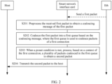
- the method includes the following several steps: S201: The smart network interface card preprocesses a received first packet to obtain a coalescing message of the first packet.
- One or more connections may be established between the host and a network (Eth) by using the smart network interface card.
- the connection may refer to a logical link established between sessions of two ends.
- the connection may include a TCP connection, a UDP connection, or an ROCE queue pair (queue pair, QP) connection.
- a first connection may be any one of the one or more connections, an identifier of the first connection may be used to identify the first connection, and the first connection may be a connection in which a stateful service is located.
- the network may transmit the packet of the first connection to the smart network interface card.
- the smart network interface card processes the packet of the first connection and transmits a processed packet to the host.
- the stateful (stateful) service corresponds to a stateless (stateless) service.
- the stateless service may be that a single packet of the service can be processed based on a header (header) of the packet, and there is no association between packets.
- the stateful service may be that how to process a single packet of the service cannot be determined by the packet. Processing of the packet needs to depend on a state of a "connection" in which the packet is located, information about the packet, and the like. In this way, a processing behavior of the packet can be determined. That is, there is an association between packets in the stateful service.
- State information of the "connection” includes but is not limited to: a sequence number of a next expected packet, an acknowledged (ACK) sequence number, and receiver window updating and statistical information.
- the firewall herein may include a firewall or may include a firewall at a different level, for example, a security group (security group) in OpenStack.
- the stateless firewall is used to filter or block a network data packet based on a static value, for example, based on an address, a port, or a protocol. In other words, the stateless firewall does not care about a current network connection state.
- the stateful firewall may distinguish a network connection state. For example, the stateful firewall may distinguish a TCP connection and a current stage of the TCP connection. In other words, in addition to a static value, the stateful firewall can further filter or block a network data packet based on a connection state.
- the smart network interface card may preprocess the first packet. For example, the smart network interface card may parse a header (header) of the first packet, to obtain the coalescing message of the first packet.
- the coalescing message may include one or more of the identifier of the first connection to which the first packet belongs, a function identifier corresponding to the first connection, and metadata.
- the function identifier corresponding to the first connection is an identifier of a first VF
- the first VF may be a VF used to receive a packet of the first connection
- the identifier of the first VF may be used to uniquely identify the first VF in a plurality of VFs in the host.
- the metadata may include a quintet of a packet, a message type of a packet, operation code indicating a message type of a packet, or the like.
- the coalescing message may include metadata, and the metadata may include a quintet, a TCP sequence number (sequence number, SN), and the like.
- the coalescing message may include metadata, and the metadata may include operation code indicating a message type of a packet.
- the operation code may include send first (send first), send middle (send middle), or send last (send last), or the operation code may include write first (write first), write middle (write middle), or write last (write last).
- S202 The smart network interface card coalesces the first packet into a first queue based on the coalescing message, where the first queue is used to coalesce packets of the first connection.
- a plurality of queues may be set in the smart network interface card. Each queue in the plurality of queues may be used to coalesce a plurality of packets from the network.
- the plurality of packets may belong to a same connection, may belong to a same message type of a same connection (for example, message types of the plurality of packets may all be write (write) data), or may belong to a plurality of consecutive packets (for example, packet numbers of the plurality of packets are consecutive) in a same message type of a same connection.
- the first queue may be any queue in the plurality of queues that is used to coalesce the packets of the first connection.
- the smart network interface card may determine whether the coalescing message meets a coalescing context of the first queue, where the coalescing context of the first queue indicates a coalescing message of the first queue.
- the coalescing context of the first queue may include an identifier of the first connection, an identifier of the first VF, a quintet of a packet, a message type of the packet, operation code of the packet, a quantity of coalesced packets, and a data volume of the coalesced packets.
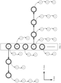
- the smart network interface card may coalesce the first packet to an X chain of the first queue as a coalescing node, and the first queue is a queue in which the packets of the first connection are coalesced. Further, the smart network interface card may further update the coalescing context of the first queue, for example, the quantity of coalesced packets in the coalescing context of the first queue is increased by 1. When the coalescing message does not meet the coalescing context of the first queue, the smart network interface card may coalesce the first packet to a Y chain of the first queue as a basic node, and update the coalescing context of the first queue based on the coalescing message.
- An updated coalescing context indicates a current coalescing message in the first queue. For example, a message type of a packet in the updated coalescing context is updated to a message type of the first packet, quintet information of the packet is updated to quintet information of the first packet, and the quantity of coalesced packets is updated to 1.
- the first packet may be coalesced to the Y chain of the first queue, and the coalescing message of the first queue is generated based on the coalescing message of the first packet.
- the identifier of the first connection and the message type of the packet in the coalescing message of the first packet are extracted as an identifier of a connection and a message type of a coalesced packet in the coalescing context of the first queue.
- the smart network interface card receives a plurality of packets from the network and the plurality of packets belong to a plurality of different connections.
- the plurality of packets include 10 packets.
- the 10 packets belong to five different connections.
- a packet A, a packet B, a packet C, a packet D, and a packet E in the 10 packets are respectively first packets successively corresponding to the five connections. Therefore, the packet A, the packet B, the packet C, the packet D, and the packet E are separately located on the Y chain of the first queue as basic nodes.
- another three packets in the 10 packets correspond to the same connection as the packet B, and are received after the packet B and before the packet A. In this way, the three packets are coalesced together with the packet B to the X chain of the first queue.
- the remaining two packets in the 10 packets correspond to the same connection as the packet E, and are received after the packet E and before the packet D. In this way, the two packets are coalesced together with the packet E to another X chain of the first queue.
- a cell (cell) chain included in each packet is represented by small circles with a number 0.
- the packet A, the packet B, the packet C, the packet D, and the packet E shown in FIG. 3 may be alternatively packets of different message types of a same connection, or packets that are of a same message type of a same connection and that have unexpected packet numbers.
- the foregoing merely uses an example in which the packet A, the packet B, the packet C, the packet D, and the packet E belong to a plurality of different connections for description. This does not constitute a limitation on this implementation of this application.
- coalescing policies may exist for different protocol types. For example, for an ROCE protocol, only packets of a same message (message) type are coalesced. For example, there are four packets: write first, write middle, write middle, and write middle. Operation code obtained after the packets are coalesced may be write first. For another example, there are four packets: write middle, write middle, write middle, and write middle. Operation code obtained after the packets are coalesced may be write middle. For another example, there are four packets: write middle, write middle, write middle, and write last. Operation code obtained after the packets are coalesced may be write last.
- S203 When a preset condition is met, the smart network interface card processes, based on a context of the first connection, a plurality of packets coalesced in the first queue to obtain a second packet.
- the preset condition may include any one of the following: coalescing duration reaches specified duration, a quantity of coalesced packets reaches a preset threshold, and a volume of coalesced data reaches a preset data volume.
- the coalescing duration, the preset threshold, and the preset data volume may be preset, and specific values of the coalescing duration, the preset threshold, and the preset data volume may be fixed or variable.
- the coalescing duration, the preset threshold, and the preset data volume may be set by a person skilled in the art based on experience or an actual situation.
- the preset data volume may be 64 KB. This is not specifically limited in this implementation of this application.
- the smart network interface card may process, based on the context of the first connection, the plurality of packets coalesced in the first queue, for example, perform L4 and L4+ processing on the plurality of packets based on the context of the first connection, and edit and chain a plurality of packets that belong to a same X chain in the first queue, to obtain the second packet.
- a cache (cache) of the smart network interface card may store the context of the first connection, or may not store the context of the first connection.
- the smart network interface card may obtain the context of the first connection from the host based on the identifier of the first connection.
- the smart network interface card may obtain the context of the first connection from the cache of the smart network interface card.
- the context of the first connection is an updated context obtained after a previous second packet of the first connection is obtained.
- S204 The smart network interface card transmits the second packet to the host.
- the smart network interface card can transmit the second packet to the host by using the PCIe bus, so that the host can receive the second packet, that is, receive a plurality of packets of the first connection.
- the host may further store the received second packet in the first VF of the first VM, where the first VM is a VM that runs the first VF in a plurality of VMs of the host.
- the smart network interface card before transmitting the second packet to the host, the smart network interface card provides a receive bandwidth for the first queue from an available bus bandwidth (for example, an available bus bandwidth corresponding to the PCIe bus), to transmit the second packet to the host by using the receive bandwidth.
- an available bus bandwidth for example, an available bus bandwidth corresponding to the PCIe bus
- the receive bandwidth may be fixed or variable, and may be specifically set by a person skilled in the art based on experience or an actual situation.
- the preset data volume may be 64 KB. This is not specifically limited in this implementation of this application.
- the smart network interface card further includes a pre-classification (pre-classification) module and an input coalescing queue (input coalescing queue, ICQ) engine (engine).
- the RX bandwidth provision module may include a queue mapping (queue mapping, QM) module, bandwidth provision nodes (represented as vNIC in FIG. 4 ), and a round robin (round robin, RR) scheduling scheduler (represented as RR in FIG. 4 ).
- QM queue mapping
- vNIC bandwidth provision nodes
- RR round robin scheduling scheduler
- the pre-classification module preprocesses the first packet to obtain the coalescing message of the first packet, for example, the identifier of the first connection, the VF ID, and the message type.
- the ICQ engine coalesces the first packet into the first queue based on the coalescing message.
- the queue mapping module maps the first queue to a corresponding bandwidth provision node to complete provision of the receive bandwidth.
- the RR provides a processor core or a thread (thread) in a processor core for the first queue from the processor pool, and the provided processor core or thread may be referred to as a core/thread hereinafter.
- the core/thread may obtain the context of the first connection based on the identifier of the first connection, and process, based on the context of the first connection, the plurality of packets coalesced in the first queue, so that the obtained second packet can be stored in a memory of the smart network interface card.
- the traffic manager may schedule the second packet from the memory and transmit the second packet to the host by using the PCIe bus.
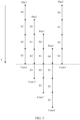
- the context of the first connection may be decomposed into a plurality of sub-contexts, so that different processor cores or threads of the smart network interface card concurrently process different packets of a same connection based on different sub-contexts, thereby improving throughput of the packets of the first connection.
- the context of the first connection may be decomposed into four sub-contexts, which are respectively represented as S0, S1, S2, and S3.
- the smart network interface card can simultaneously process packets coalesced in four coalescing queues corresponding to the first connection, and the packets coalesced in the four coalescing queues may be respectively represented as pad, pac2, pac3, and pac4.
- processor cores provided by the scheduler for the four packets are respectively Core1, Core2, Core3, and Core4.
- the Core1 may continue processing of pad S1.
- the Core2 may perform processing of pac2 S0.
- the Core1 may continue processing of pad 1 S2.
- the Core2 completes processing of pac2 S0 and may start to perform processing of pac2 S1.
- the Core3 may start to perform processing of pac3 S0, ..., and so on.
- the Core1 may start to perform processing of pac5 S0, the Core2 starts to perform processing of pac2 S3, the Core3 starts to perform processing of pac3 S2, and the Core4 starts to perform processing of pac4 S1.
- the four cores of the smart network interface card can concurrently participate in context processing of the first connection, and each core can process a second packet of one first connection, thereby improving the throughput of the packets of the first connection.
- the smart network interface card can preprocess the received first packet, to obtain the coalescing message of the first packet, and coalesce, based on the coalescing message, the first packet into the first queue used to coalesce the packets of the first connection, so that when the preset condition is met, the plurality of packets coalesced in the first queue are processed based on the context of the first connection, to obtain the second packet.
- the smart network interface card can obtain the context of the first connection only once, and process the plurality of packets of the first connection based on the context, thereby improving processing performance of a single stateful service.
- the smart network interface card may be divided into functional modules based on the foregoing method examples.
- each functional module may be obtained through division corresponding to each function, or two or more functions may be integrated into one module.
- the integrated module may be implemented in a form of hardware, or may be implemented in a form of a software functional module.
- division into the modules is an example and is merely logical function division, and may be other division in an actual implementation. The following uses an example in which each functional module is obtained through division corresponding to each function for description.
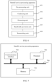
- FIG. 6 is a schematic diagram of a possible structure of a stateful service processing apparatus in the foregoing implementation.
- the apparatus may be a smart network interface card or a chip built in a smart network interface card.
- the apparatus includes a preprocessing unit 601, a coalescing unit 602, a processing unit 603, and a transmitting unit 604.
- the preprocessing unit 601 is configured to support the apparatus in performing S201 in the foregoing method implementation.
- the coalescing unit 602 is configured to support the apparatus in performing S202 in the foregoing method implementation.
- the processing unit 603 is configured to support the apparatus in performing S203 in the foregoing method implementation.
- the transmitting unit 604 is configured to support the apparatus in performing S204 in the foregoing method implementation.
- the apparatus may further include a bandwidth provision unit 605, configured to support the apparatus in performing the step of providing the receive bandwidth in the foregoing method implementation.
- the preprocessing unit 601 may be the pre-classification module in the smart network interface card described in the foregoing method implementation.
- the coalescing unit 602 may be the ICQ engine in the smart network interface card described in the foregoing method implementation.
- the processing unit 603 may be the processor pool in the smart network interface card described in the foregoing method implementation.
- the transmitting unit 604 may be the RV VM in the smart network interface card described in the foregoing method implementation.
- the bandwidth provision unit 605 may be the RX bandwidth provision module in the smart network interface card described in the foregoing method implementation.
- the preprocessing unit 601, the coalescing unit 602, and the processing unit 603 in this application may be integrated as a processor of the apparatus, and the transmitting unit 604 may be used as a communication interface of the apparatus.
- FIG. 7 is a schematic diagram of a possible logical structure of a stateful service processing apparatus related to the foregoing implementation according to an implementation of this application.
- the apparatus may be a smart network interface card or a chip built in a smart network interface card, and the apparatus includes a processor 702 and a communication interface 703.
- the processor 702 is configured to control and manage an action of the apparatus.
- the processor 702 is configured to support the apparatus in performing S201, S202, and S203 in the foregoing method implementation, and/or is configured to perform another process of the technology described herein.
- the apparatus may further include a memory 701 and a bus 704.
- the processor 702, the communication interface 703, and the memory 701 are connected to each other by using the bus 704.
- the communication interface 703 is configured to support the apparatus in communication, for example, support the apparatus in communicating with a host.
- the memory 701 is configured to store program code and data of the apparatus.
- the processor 702 may be a central processing unit, a general-purpose processor, a digital signal processor, an application-specific integrated circuit, a field programmable gate array or another programmable logic device, a transistor logic device, a hardware component, or any combination thereof.
- the processor 702 may implement or execute logical blocks, modules, and circuits in various examples described with reference to content disclosed in this application.
- the processor may be alternatively a combination for implementing a computing function, for example, a combination including one or more microprocessors, or a combination of a digital signal processor and a microprocessor.
- the bus 704 may be a peripheral component interconnect (peripheral component interconnect, PCI) bus, an extended industry standard architecture (extended industry standard architecture, EISA) bus, or the like.
- the bus 704 may be classified into an address bus, a data bus, a control bus, and the like. For ease of representation, only one bold line is used for representation in FIG. 7 , but this does not mean that there is only one bus
- a communication system including a network interface card and a host, and the network interface card is connected to the host by using a bus.
- the network interface card is any network interface card provided above, and is configured to perform the steps performed by the network interface card in the foregoing method implementation.
- the units described as separate parts may or may not be physically separate, and parts displayed as units may be one or more physical units, that is, may be located in one place, or may be distributed in a plurality of different places. Some or all of the units may be selected based on an actual requirement to achieve the objectives of the solutions of implementations.
- each of the units may exist alone physically, or two or more units may be integrated into one unit.
- the integrated unit may be implemented in a form of hardware, or may be implemented in a form of a software function unit.
- the integrated unit may be stored in a readable storage medium.
- the readable storage medium may include any medium that can store program code, for example, a USB flash drive, a removable hard disk, a read-only memory, a random access memory, a magnetic disk, or an optical disc.
- a readable storage medium stores computer executable instructions.
- a device which may be a single-chip microcomputer, a chip, or the like
- a processor performs the stateful service processing method provided in the foregoing method implementation
- a computer program product is further provided.
- the computer program product includes computer executable instructions, where the computer executable instructions are stored in a computer-readable storage medium.
- At least one processor of a device may read the computer executable instructions from the computer-readable storage medium, and the at least one processor executes the computer executable instructions, to enable the device to perform the stateful service processing method provided in the foregoing method implementation.
Landscapes
- Engineering & Computer Science (AREA)
- Computer Networks & Wireless Communication (AREA)
- Signal Processing (AREA)
- Data Exchanges In Wide-Area Networks (AREA)
Claims (7)
- Verfahren zur Verarbeitung eines zustandsbehafteten Dienstes, wobei das Verfahren auf eine Netzwerkschnittstellenkarte angewandt wird, die Netzwerkschnittstellenkarte mit einem Host unter Verwendung eines Busses verbunden ist und das Verfahren umfasst:Vorverarbeiten (S201) eines von einem Netzwerk empfangenen ersten Pakets, um eine Koaleszenznachricht des ersten Pakets zu erlangen, wobei das erste Paket von einer ersten Verbindung ist, die erste Verbindung eine Verbindung ist, in der ein zustandsbehafteter Dienst angeordnet ist, und wobei die Koaleszenznachricht des ersten Pakets mindestens eines von Folgendem umfasst: eine Kennung der ersten Verbindung, eine Funktionskennung der ersten Verbindung, wobei die Koaleszenznachricht des ersten Pakets ferner Metadaten umfasst, wobei die Metadaten einen Nachrichtentyp des ersten Pakets enthalten;wenn die Koaleszenznachricht des ersten Pakets einem Koaleszenzkontext einer ersten Warteschlange entspricht, Koaleszieren (S202) des ersten Pakets in die erste Warteschlange, wobei die erste Warteschlange eine beliebige Warteschlange in einer Vielzahl von Warteschlangen ist, die verwendet wird, Pakete der ersten Verbindung zu koaleszieren, wobei jede Warteschlange in der Vielzahl von Warteschlangen verwendet wird, eine von dem Netzwerk empfangene Vielzahl von Paketen zu koaleszieren, wobei die Vielzahl von Paketen zu einer selben Verbindung gehört oder die Vielzahl von Paketen zu einem selben Nachrichtentyp einer selben Verbindung gehört und wobei der Koaleszenzkontext der ersten Warteschlange die Kennung der ersten Verbindung und den Nachrichtentyp des ersten Pakets enthält;wenn eine im Voraus eingestellte Bedingung erfüllt wird, Verarbeiten (S203), basierend auf einem Kontext der ersten Verbindung, einer in der ersten Warteschlange koaleszierten Vielzahl von Paketen, um ein zweites Paket zu erlangen, wobei der Kontext der ersten Verbindung zugehörige Informationen der ersten Verbindung angibt und der Kontext der ersten Verbindung ein aktualisierter Kontext ist, der erlangt wird, nachdem ein vorheriges zweites Paket der ersten Verbindung erlangt wird, und Übertragen (S204) des zweiten Pakets an den Host.
- Verfahren nach Anspruch 1, wobei die im Voraus eingestellte Bedingung ein beliebiges des Folgenden umfasst: eine Koaleszenzdauer erreicht eine spezifizierte Dauer, eine Quantität von koaleszierten Paketen erreicht einen im Voraus eingestellten Schwellenwert und ein Volumen von koaleszierten Daten erreicht ein im Voraus eingestelltes Datenvolumen.
- Verfahren nach Anspruch 1 oder 2, wobei das Verfahren ferner umfasst:Bereitstellen einer Empfangsbandbreite für die erste Warteschlange aus einer verfügbaren Busbandbreite; undentsprechend das Übertragen des zweiten Pakets an den Host umfasst: Übertragen des zweiten Pakets an den Host unter Verwendung der Empfangsbandbreite.
- Vorrichtung zur Verarbeitung eines zustandsbehafteten Dienstes, wobei die Vorrichtung auf eine Netzwerkschnittstellenkarte angewandt wird, die Netzwerkschnittstellenkarte mit einem Host unter Verwendung eines Busses verbunden ist und die Vorrichtung umfasst:eine Vorverarbeitungseinheit (601), konfiguriert zum Vorverarbeiten eines von einem Netzwerk empfangenen ersten Pakets, um eine Koaleszenznachricht des ersten Pakets zu erlangen, wobei das erste Paket von einer ersten Verbindung ist, die erste Verbindung eine Verbindung ist, in der ein zustandsbehafteter Dienst angeordnet ist, und wobei die Koaleszenznachricht des ersten Pakets mindestens eines von Folgendem umfasst: eine Kennung der ersten Verbindung, eine Funktionskennung der ersten Verbindung, wobei die Koaleszenznachricht des ersten Pakets ferner Metadaten umfasst, wobei die Metadaten einen Nachrichtentyp des ersten Pakets enthalten;eine Koaleszierungseinheit (602), konfiguriert zum, wenn die Koaleszenznachricht des ersten Pakets einem Koaleszenzkontext einer ersten Warteschlange entspricht, Koaleszieren des ersten Pakets in die erste Warteschlange, wobei die erste Warteschlange eine beliebige Warteschlange in einer Vielzahl von Warteschlangen ist, die verwendet wird, Pakete der ersten Verbindung zu koaleszieren, wobei jede Warteschlange in der Vielzahl von Warteschlangen verwendet wird, eine von dem Netzwerk empfangene Vielzahl von Paketen zu koaleszieren, wobei die Vielzahl von Paketen zu einer selben Verbindung gehört oder die Vielzahl von Paketen zu einem selben Nachrichtentyp einer selben Verbindung gehört und wobei der Koaleszenzkontext der ersten Warteschlange die Kennung der ersten Verbindung und den Nachrichtentyp des ersten Pakets enthält;eine Verarbeitungseinheit (603), konfiguriert zum: wenn eine im Voraus eingestellte Bedingung erfüllt wird, Verarbeiten, basierend auf einem Kontext der ersten Verbindung, einer in der ersten Warteschlange koaleszierten Vielzahl von Paketen, um ein zweites Paket zu erlangen, wobei der Kontext der ersten Verbindung zugehörige Informationen der ersten Verbindung angibt und der Kontext der ersten Verbindung ein aktualisierter Kontext ist, der erlangt wird, nachdem ein vorheriges zweites Paket der ersten Verbindung erlangt wird, undeine Übertragungseinheit (604), konfiguriert zum Übertragen des zweiten Pakets an den Host.
- Vorrichtung nach Anspruch 4, wobei die im Voraus eingestellte Bedingung ein beliebiges des Folgenden umfasst: eine Koaleszenzdauer erreicht eine spezifizierte Dauer, eine Quantität von koaleszierten Paketen erreicht einen im Voraus eingestellten Schwellenwert und ein Volumen von koaleszierten Daten erreicht ein im Voraus eingestelltes Datenvolumen.
- Vorrichtung nach Anspruch 4 oder 5, wobei die Vorrichtung ferner umfasst:eine Bandbreitenbereitstellungseinheit (605), konfiguriert zum Bereitstellen einer Empfangsbandbreite für die erste Warteschlange aus einer verfügbaren Busbandbreite; undentsprechend die Übertragungseinheit ferner konfiguriert ist zum Übertragen des zweiten Pakets an den Host unter Verwendung der Empfangsbandbreite.
- Computerlesbares Speichermedium, wobei das computerlesbare Speichermedium Anweisungen speichert, und wenn die Anweisungen auf einem Computer ausgeführt werden, der Computer in die Lage versetzt wird, das Verfahren zur Verarbeitung eines zustandsbehafteten Dienstes nach einem der Ansprüche 1 bis 3 durchzuführen.
Applications Claiming Priority (1)
| Application Number | Priority Date | Filing Date | Title |
|---|---|---|---|
| PCT/CN2020/085433 WO2021208101A1 (zh) | 2020-04-17 | 2020-04-17 | 一种有状态业务的处理方法及装置 |
Publications (3)
| Publication Number | Publication Date |
|---|---|
| EP4131880A1 EP4131880A1 (de) | 2023-02-08 |
| EP4131880A4 EP4131880A4 (de) | 2023-03-15 |
| EP4131880B1 true EP4131880B1 (de) | 2024-11-27 |
Family
ID=78083512
Family Applications (1)
| Application Number | Title | Priority Date | Filing Date |
|---|---|---|---|
| EP20931437.6A Active EP4131880B1 (de) | 2020-04-17 | 2020-04-17 | Verfahren und vorrichtung zur verarbeitung eines zustandsbehafteten dienstes |
Country Status (4)
| Country | Link |
|---|---|
| US (1) | US12199883B2 (de) |
| EP (1) | EP4131880B1 (de) |
| CN (1) | CN115349247B (de) |
| WO (1) | WO2021208101A1 (de) |
Families Citing this family (5)
| Publication number | Priority date | Publication date | Assignee | Title |
|---|---|---|---|---|
| US12015562B2 (en) * | 2021-04-29 | 2024-06-18 | Oracle International Corporation | Port addressing via packet header modification |
| US12015557B2 (en) | 2021-07-29 | 2024-06-18 | Oracle International Corportion | Efficient flow management utilizing unified logging |
| US12021757B2 (en) * | 2022-03-18 | 2024-06-25 | Oracle International Corporation | Bandwidth control inside a shared network interface card |
| US11924086B2 (en) | 2022-05-18 | 2024-03-05 | Oracle International Corporation | Load-based management for NVME over TCP connections |
| US20240396840A1 (en) * | 2023-05-26 | 2024-11-28 | Mangoboost Inc. | Toe-based network interface device capable of asynchronous performing tcp event handling and tcp operation processing, operation method thereof, and server device including the same |
Family Cites Families (10)
| Publication number | Priority date | Publication date | Assignee | Title |
|---|---|---|---|---|
| US7620071B2 (en) * | 2004-11-16 | 2009-11-17 | Intel Corporation | Packet coalescing |
| US20070033301A1 (en) * | 2005-07-18 | 2007-02-08 | Eliezer Aloni | Method and system for transparent TCP offload with dynamic zero copy sending |
| CN101123567A (zh) * | 2006-05-01 | 2008-02-13 | 美国博通公司 | 用于处理网络信息的方法及系统 |
| CN103425524B (zh) * | 2013-07-17 | 2017-02-08 | 北京邮电大学 | 一种均衡多业务终端聚合的方法和系统 |
| US9384033B2 (en) * | 2014-03-11 | 2016-07-05 | Vmware, Inc. | Large receive offload for virtual machines |
| CN105245387A (zh) * | 2015-10-26 | 2016-01-13 | 华为技术有限公司 | 一种处理报文的方法及系统 |
| CN108881008B (zh) * | 2017-05-12 | 2021-06-08 | 华为技术有限公司 | 一种数据传输的方法、装置和系统 |
| CN110851371B (zh) * | 2018-08-20 | 2023-09-26 | 华为技术有限公司 | 报文处理方法及相关设备 |
| CN110138809A (zh) * | 2019-06-27 | 2019-08-16 | 西安微电子技术研究所 | 一种面向以太网控制器接收链路的tcp报文拼接系统和方法 |
| US11831742B2 (en) * | 2019-12-12 | 2023-11-28 | Intel Corporation | Semi-flexible packet coalescing control path |
-
2020
- 2020-04-17 CN CN202080099178.XA patent/CN115349247B/zh active Active
- 2020-04-17 EP EP20931437.6A patent/EP4131880B1/de active Active
- 2020-04-17 WO PCT/CN2020/085433 patent/WO2021208101A1/zh not_active Ceased
-
2022
- 2022-10-13 US US17/965,112 patent/US12199883B2/en active Active
Also Published As
| Publication number | Publication date |
|---|---|
| WO2021208101A1 (zh) | 2021-10-21 |
| EP4131880A1 (de) | 2023-02-08 |
| CN115349247A (zh) | 2022-11-15 |
| US20230029796A1 (en) | 2023-02-02 |
| EP4131880A4 (de) | 2023-03-15 |
| US12199883B2 (en) | 2025-01-14 |
| CN115349247B (zh) | 2025-07-04 |
Similar Documents
| Publication | Publication Date | Title |
|---|---|---|
| EP4131880B1 (de) | Verfahren und vorrichtung zur verarbeitung eines zustandsbehafteten dienstes | |
| CN111176792B (zh) | 一种资源调度方法、装置及相关设备 | |
| US9965441B2 (en) | Adaptive coalescing of remote direct memory access acknowledgements based on I/O characteristics | |
| CN114189571B (zh) | 用于实施加速网络分组处理的装置和方法 | |
| US9703589B2 (en) | Networking stack of virtualization software configured to support latency sensitive virtual machines | |
| US10411953B2 (en) | Virtual machine fault tolerance method, apparatus, and system | |
| EP3275140B1 (de) | Technik zur erreichung von niedriger latenz in datenzentrumsnetzwerkumgebungen | |
| CN115349121A (zh) | 一种有状态业务的处理方法及装置 | |
| CN109688063B (zh) | 一种大型接收卸载功能的设置方法和装置 | |
| CN114666276B (zh) | 一种发送报文的方法和装置 | |
| CN114153778A (zh) | 跨网络桥接 | |
| CN108965148A (zh) | 一种处理器及报文处理方法 | |
| CN114691286A (zh) | 服务器系统、虚拟机创建方法及装置 | |
| CN112422448A (zh) | Fpga加速卡网络数据传输方法及相关组件 | |
| CN105335211A (zh) | 一种基于Xen虚拟化集群的FPGA加速器调度系统及方法 | |
| CN104158675B (zh) | 计算节点部署方法、处理节点、控制器及系统 | |
| WO2017218700A1 (en) | Systems and methods for non-uniform memory access aligned i/o for virtual machines | |
| DE102024128700A1 (de) | Paketpuffertechnologien | |
| CN116095028A (zh) | 报文发送方法、设备及可读存储介质 | |
| CN107659511B (zh) | 一种过载控制方法、主机和存储介质以及程序产品 | |
| US20250233834A1 (en) | Data path rule management in virtual switch | |
| DE102023130645A1 (de) | Auswahl von hardware-ressourcen | |
| EP3016333A1 (de) | Handhabung von Netzwerkdatenpaketen mit hohem Durchsatz und mit geringer Latenz in einer Verkehrsverwaltungsvorrichtung | |
| CN114827312B (zh) | 在智能网卡/dpu内自适应延迟及吞吐率需求的方法及装置 | |
| CN119071310A (zh) | 云存储处理方法、设备、存储介质和系统 |
Legal Events
| Date | Code | Title | Description |
|---|---|---|---|
| STAA | Information on the status of an ep patent application or granted ep patent |
Free format text: STATUS: THE INTERNATIONAL PUBLICATION HAS BEEN MADE |
|
| PUAI | Public reference made under article 153(3) epc to a published international application that has entered the european phase |
Free format text: ORIGINAL CODE: 0009012 |
|
| STAA | Information on the status of an ep patent application or granted ep patent |
Free format text: STATUS: REQUEST FOR EXAMINATION WAS MADE |
|
| REG | Reference to a national code |
Ref country code: DE Ref legal event code: R079 Free format text: PREVIOUS MAIN CLASS: H04L0029060000 Ipc: G06F0013120000 Ref document number: 602020042313 Country of ref document: DE |
|
| 17P | Request for examination filed |
Effective date: 20221028 |
|
| AK | Designated contracting states |
Kind code of ref document: A1 Designated state(s): AL AT BE BG CH CY CZ DE DK EE ES FI FR GB GR HR HU IE IS IT LI LT LU LV MC MK MT NL NO PL PT RO RS SE SI SK SM TR |
|
| A4 | Supplementary search report drawn up and despatched |
Effective date: 20230210 |
|
| RIC1 | Information provided on ipc code assigned before grant |
Ipc: H04L 47/10 20220101ALI20230207BHEP Ipc: G06F 13/12 20060101AFI20230207BHEP |
|
| DAV | Request for validation of the european patent (deleted) | ||
| DAX | Request for extension of the european patent (deleted) | ||
| STAA | Information on the status of an ep patent application or granted ep patent |
Free format text: STATUS: EXAMINATION IS IN PROGRESS |
|
| 17Q | First examination report despatched |
Effective date: 20231218 |
|
| GRAP | Despatch of communication of intention to grant a patent |
Free format text: ORIGINAL CODE: EPIDOSNIGR1 |
|
| STAA | Information on the status of an ep patent application or granted ep patent |
Free format text: STATUS: GRANT OF PATENT IS INTENDED |
|
| INTG | Intention to grant announced |
Effective date: 20240710 |
|
| GRAS | Grant fee paid |
Free format text: ORIGINAL CODE: EPIDOSNIGR3 |
|
| GRAA | (expected) grant |
Free format text: ORIGINAL CODE: 0009210 |
|
| STAA | Information on the status of an ep patent application or granted ep patent |
Free format text: STATUS: THE PATENT HAS BEEN GRANTED |
|
| AK | Designated contracting states |
Kind code of ref document: B1 Designated state(s): AL AT BE BG CH CY CZ DE DK EE ES FI FR GB GR HR HU IE IS IT LI LT LU LV MC MK MT NL NO PL PT RO RS SE SI SK SM TR |
|
| REG | Reference to a national code |
Ref country code: GB Ref legal event code: FG4D |
|
| REG | Reference to a national code |
Ref country code: CH Ref legal event code: EP |
|
| REG | Reference to a national code |
Ref country code: DE Ref legal event code: R096 Ref document number: 602020042313 Country of ref document: DE |
|
| REG | Reference to a national code |
Ref country code: IE Ref legal event code: FG4D |
|
| REG | Reference to a national code |
Ref country code: LT Ref legal event code: MG9D |
|
| REG | Reference to a national code |
Ref country code: NL Ref legal event code: MP Effective date: 20241127 |
|
| PG25 | Lapsed in a contracting state [announced via postgrant information from national office to epo] |
Ref country code: HR Free format text: LAPSE BECAUSE OF FAILURE TO SUBMIT A TRANSLATION OF THE DESCRIPTION OR TO PAY THE FEE WITHIN THE PRESCRIBED TIME-LIMIT Effective date: 20241127 Ref country code: IS Free format text: LAPSE BECAUSE OF FAILURE TO SUBMIT A TRANSLATION OF THE DESCRIPTION OR TO PAY THE FEE WITHIN THE PRESCRIBED TIME-LIMIT Effective date: 20250327 Ref country code: PT Free format text: LAPSE BECAUSE OF FAILURE TO SUBMIT A TRANSLATION OF THE DESCRIPTION OR TO PAY THE FEE WITHIN THE PRESCRIBED TIME-LIMIT Effective date: 20250327 |
|
| PG25 | Lapsed in a contracting state [announced via postgrant information from national office to epo] |
Ref country code: FI Free format text: LAPSE BECAUSE OF FAILURE TO SUBMIT A TRANSLATION OF THE DESCRIPTION OR TO PAY THE FEE WITHIN THE PRESCRIBED TIME-LIMIT Effective date: 20241127 Ref country code: NL Free format text: LAPSE BECAUSE OF FAILURE TO SUBMIT A TRANSLATION OF THE DESCRIPTION OR TO PAY THE FEE WITHIN THE PRESCRIBED TIME-LIMIT Effective date: 20241127 |
|
| REG | Reference to a national code |
Ref country code: AT Ref legal event code: MK05 Ref document number: 1746360 Country of ref document: AT Kind code of ref document: T Effective date: 20241127 |
|
| PG25 | Lapsed in a contracting state [announced via postgrant information from national office to epo] |
Ref country code: BG Free format text: LAPSE BECAUSE OF FAILURE TO SUBMIT A TRANSLATION OF THE DESCRIPTION OR TO PAY THE FEE WITHIN THE PRESCRIBED TIME-LIMIT Effective date: 20241127 |
|
| PG25 | Lapsed in a contracting state [announced via postgrant information from national office to epo] |
Ref country code: ES Free format text: LAPSE BECAUSE OF FAILURE TO SUBMIT A TRANSLATION OF THE DESCRIPTION OR TO PAY THE FEE WITHIN THE PRESCRIBED TIME-LIMIT Effective date: 20241127 |
|
| PG25 | Lapsed in a contracting state [announced via postgrant information from national office to epo] |
Ref country code: NO Free format text: LAPSE BECAUSE OF FAILURE TO SUBMIT A TRANSLATION OF THE DESCRIPTION OR TO PAY THE FEE WITHIN THE PRESCRIBED TIME-LIMIT Effective date: 20250227 |
|
| PG25 | Lapsed in a contracting state [announced via postgrant information from national office to epo] |
Ref country code: LV Free format text: LAPSE BECAUSE OF FAILURE TO SUBMIT A TRANSLATION OF THE DESCRIPTION OR TO PAY THE FEE WITHIN THE PRESCRIBED TIME-LIMIT Effective date: 20241127 Ref country code: GR Free format text: LAPSE BECAUSE OF FAILURE TO SUBMIT A TRANSLATION OF THE DESCRIPTION OR TO PAY THE FEE WITHIN THE PRESCRIBED TIME-LIMIT Effective date: 20250228 Ref country code: AT Free format text: LAPSE BECAUSE OF FAILURE TO SUBMIT A TRANSLATION OF THE DESCRIPTION OR TO PAY THE FEE WITHIN THE PRESCRIBED TIME-LIMIT Effective date: 20241127 |
|
| PG25 | Lapsed in a contracting state [announced via postgrant information from national office to epo] |
Ref country code: PL Free format text: LAPSE BECAUSE OF FAILURE TO SUBMIT A TRANSLATION OF THE DESCRIPTION OR TO PAY THE FEE WITHIN THE PRESCRIBED TIME-LIMIT Effective date: 20241127 |
|
| PG25 | Lapsed in a contracting state [announced via postgrant information from national office to epo] |
Ref country code: RS Free format text: LAPSE BECAUSE OF FAILURE TO SUBMIT A TRANSLATION OF THE DESCRIPTION OR TO PAY THE FEE WITHIN THE PRESCRIBED TIME-LIMIT Effective date: 20250227 |
|
| PG25 | Lapsed in a contracting state [announced via postgrant information from national office to epo] |
Ref country code: SM Free format text: LAPSE BECAUSE OF FAILURE TO SUBMIT A TRANSLATION OF THE DESCRIPTION OR TO PAY THE FEE WITHIN THE PRESCRIBED TIME-LIMIT Effective date: 20241127 |
|
| PGFP | Annual fee paid to national office [announced via postgrant information from national office to epo] |
Ref country code: DE Payment date: 20250305 Year of fee payment: 6 |
|
| PG25 | Lapsed in a contracting state [announced via postgrant information from national office to epo] |
Ref country code: DK Free format text: LAPSE BECAUSE OF FAILURE TO SUBMIT A TRANSLATION OF THE DESCRIPTION OR TO PAY THE FEE WITHIN THE PRESCRIBED TIME-LIMIT Effective date: 20241127 |
|
| PG25 | Lapsed in a contracting state [announced via postgrant information from national office to epo] |
Ref country code: EE Free format text: LAPSE BECAUSE OF FAILURE TO SUBMIT A TRANSLATION OF THE DESCRIPTION OR TO PAY THE FEE WITHIN THE PRESCRIBED TIME-LIMIT Effective date: 20241127 |
|
| PG25 | Lapsed in a contracting state [announced via postgrant information from national office to epo] |
Ref country code: RO Free format text: LAPSE BECAUSE OF FAILURE TO SUBMIT A TRANSLATION OF THE DESCRIPTION OR TO PAY THE FEE WITHIN THE PRESCRIBED TIME-LIMIT Effective date: 20241127 |
|
| PG25 | Lapsed in a contracting state [announced via postgrant information from national office to epo] |
Ref country code: SK Free format text: LAPSE BECAUSE OF FAILURE TO SUBMIT A TRANSLATION OF THE DESCRIPTION OR TO PAY THE FEE WITHIN THE PRESCRIBED TIME-LIMIT Effective date: 20241127 |
|
| PG25 | Lapsed in a contracting state [announced via postgrant information from national office to epo] |
Ref country code: CZ Free format text: LAPSE BECAUSE OF FAILURE TO SUBMIT A TRANSLATION OF THE DESCRIPTION OR TO PAY THE FEE WITHIN THE PRESCRIBED TIME-LIMIT Effective date: 20241127 |
|
| PG25 | Lapsed in a contracting state [announced via postgrant information from national office to epo] |
Ref country code: IT Free format text: LAPSE BECAUSE OF FAILURE TO SUBMIT A TRANSLATION OF THE DESCRIPTION OR TO PAY THE FEE WITHIN THE PRESCRIBED TIME-LIMIT Effective date: 20241127 |
|
| REG | Reference to a national code |
Ref country code: DE Ref legal event code: R097 Ref document number: 602020042313 Country of ref document: DE |
|
| PG25 | Lapsed in a contracting state [announced via postgrant information from national office to epo] |
Ref country code: SE Free format text: LAPSE BECAUSE OF FAILURE TO SUBMIT A TRANSLATION OF THE DESCRIPTION OR TO PAY THE FEE WITHIN THE PRESCRIBED TIME-LIMIT Effective date: 20241127 |
|
| PLBE | No opposition filed within time limit |
Free format text: ORIGINAL CODE: 0009261 |
|
| STAA | Information on the status of an ep patent application or granted ep patent |
Free format text: STATUS: NO OPPOSITION FILED WITHIN TIME LIMIT |
|
| REG | Reference to a national code |
Ref country code: CH Ref legal event code: L10 Free format text: ST27 STATUS EVENT CODE: U-0-0-L10-L00 (AS PROVIDED BY THE NATIONAL OFFICE) Effective date: 20251008 |
|
| 26N | No opposition filed |
Effective date: 20250828 |
|
| REG | Reference to a national code |
Ref country code: CH Ref legal event code: H13 Free format text: ST27 STATUS EVENT CODE: U-0-0-H10-H13 (AS PROVIDED BY THE NATIONAL OFFICE) Effective date: 20251125 |
|
| PG25 | Lapsed in a contracting state [announced via postgrant information from national office to epo] |
Ref country code: LU Free format text: LAPSE BECAUSE OF NON-PAYMENT OF DUE FEES Effective date: 20250417 |
|
| PG25 | Lapsed in a contracting state [announced via postgrant information from national office to epo] |
Ref country code: MC Free format text: LAPSE BECAUSE OF FAILURE TO SUBMIT A TRANSLATION OF THE DESCRIPTION OR TO PAY THE FEE WITHIN THE PRESCRIBED TIME-LIMIT Effective date: 20241127 |
|
| GBPC | Gb: european patent ceased through non-payment of renewal fee |
Effective date: 20250417 |
|
| REG | Reference to a national code |
Ref country code: BE Ref legal event code: MM Effective date: 20250430 |
|
| PG25 | Lapsed in a contracting state [announced via postgrant information from national office to epo] |
Ref country code: GB Free format text: LAPSE BECAUSE OF NON-PAYMENT OF DUE FEES Effective date: 20250417 |
|
| PG25 | Lapsed in a contracting state [announced via postgrant information from national office to epo] |
Ref country code: FR Free format text: LAPSE BECAUSE OF NON-PAYMENT OF DUE FEES Effective date: 20250430 |
|
| PG25 | Lapsed in a contracting state [announced via postgrant information from national office to epo] |
Ref country code: BE Free format text: LAPSE BECAUSE OF NON-PAYMENT OF DUE FEES Effective date: 20250430 |
|
| PG25 | Lapsed in a contracting state [announced via postgrant information from national office to epo] |
Ref country code: CH Free format text: LAPSE BECAUSE OF NON-PAYMENT OF DUE FEES Effective date: 20250430 |