EP4131799A1 - Antenna determination method and apparatus, terminal, electronic device, and storage medium - Google Patents
Antenna determination method and apparatus, terminal, electronic device, and storage medium Download PDFInfo
- Publication number
- EP4131799A1 EP4131799A1 EP21834426.5A EP21834426A EP4131799A1 EP 4131799 A1 EP4131799 A1 EP 4131799A1 EP 21834426 A EP21834426 A EP 21834426A EP 4131799 A1 EP4131799 A1 EP 4131799A1
- Authority
- EP
- European Patent Office
- Prior art keywords
- terminal device
- antenna
- signal
- antennas
- signal quality
- Prior art date
- Legal status (The legal status is an assumption and is not a legal conclusion. Google has not performed a legal analysis and makes no representation as to the accuracy of the status listed.)
- Pending
Links
Images


Classifications
-
- H—ELECTRICITY
- H04—ELECTRIC COMMUNICATION TECHNIQUE
- H04W—WIRELESS COMMUNICATION NETWORKS
- H04W4/00—Services specially adapted for wireless communication networks; Facilities therefor
- H04W4/30—Services specially adapted for particular environments, situations or purposes
- H04W4/40—Services specially adapted for particular environments, situations or purposes for vehicles, e.g. vehicle-to-pedestrians [V2P]
- H04W4/44—Services specially adapted for particular environments, situations or purposes for vehicles, e.g. vehicle-to-pedestrians [V2P] for communication between vehicles and infrastructures, e.g. vehicle-to-cloud [V2C] or vehicle-to-home [V2H]
-
- H—ELECTRICITY
- H04—ELECTRIC COMMUNICATION TECHNIQUE
- H04B—TRANSMISSION
- H04B7/00—Radio transmission systems, i.e. using radiation field
- H04B7/02—Diversity systems; Multi-antenna system, i.e. transmission or reception using multiple antennas
- H04B7/04—Diversity systems; Multi-antenna system, i.e. transmission or reception using multiple antennas using two or more spaced independent antennas
- H04B7/06—Diversity systems; Multi-antenna system, i.e. transmission or reception using multiple antennas using two or more spaced independent antennas at the transmitting station
- H04B7/0602—Diversity systems; Multi-antenna system, i.e. transmission or reception using multiple antennas using two or more spaced independent antennas at the transmitting station using antenna switching
- H04B7/0608—Antenna selection according to transmission parameters
-
- H—ELECTRICITY
- H04—ELECTRIC COMMUNICATION TECHNIQUE
- H04B—TRANSMISSION
- H04B7/00—Radio transmission systems, i.e. using radiation field
- H04B7/02—Diversity systems; Multi-antenna system, i.e. transmission or reception using multiple antennas
- H04B7/04—Diversity systems; Multi-antenna system, i.e. transmission or reception using multiple antennas using two or more spaced independent antennas
- H04B7/08—Diversity systems; Multi-antenna system, i.e. transmission or reception using multiple antennas using two or more spaced independent antennas at the receiving station
- H04B7/0802—Diversity systems; Multi-antenna system, i.e. transmission or reception using multiple antennas using two or more spaced independent antennas at the receiving station using antenna selection
- H04B7/0805—Diversity systems; Multi-antenna system, i.e. transmission or reception using multiple antennas using two or more spaced independent antennas at the receiving station using antenna selection with single receiver and antenna switching
- H04B7/0814—Diversity systems; Multi-antenna system, i.e. transmission or reception using multiple antennas using two or more spaced independent antennas at the receiving station using antenna selection with single receiver and antenna switching based on current reception conditions, e.g. switching to different antenna when signal level is below threshold
-
- H—ELECTRICITY
- H04—ELECTRIC COMMUNICATION TECHNIQUE
- H04W—WIRELESS COMMUNICATION NETWORKS
- H04W4/00—Services specially adapted for wireless communication networks; Facilities therefor
- H04W4/30—Services specially adapted for particular environments, situations or purposes
- H04W4/40—Services specially adapted for particular environments, situations or purposes for vehicles, e.g. vehicle-to-pedestrians [V2P]
- H04W4/46—Services specially adapted for particular environments, situations or purposes for vehicles, e.g. vehicle-to-pedestrians [V2P] for vehicle-to-vehicle communication [V2V]
-
- H—ELECTRICITY
- H04—ELECTRIC COMMUNICATION TECHNIQUE
- H04W—WIRELESS COMMUNICATION NETWORKS
- H04W72/00—Local resource management
- H04W72/02—Selection of wireless resources by user or terminal
-
- H—ELECTRICITY
- H04—ELECTRIC COMMUNICATION TECHNIQUE
- H04W—WIRELESS COMMUNICATION NETWORKS
- H04W72/00—Local resource management
- H04W72/04—Wireless resource allocation
- H04W72/044—Wireless resource allocation based on the type of the allocated resource
- H04W72/046—Wireless resource allocation based on the type of the allocated resource the resource being in the space domain, e.g. beams
-
- H—ELECTRICITY
- H04—ELECTRIC COMMUNICATION TECHNIQUE
- H04W—WIRELESS COMMUNICATION NETWORKS
- H04W72/00—Local resource management
- H04W72/40—Resource management for direct mode communication, e.g. D2D or sidelink
-
- H—ELECTRICITY
- H04—ELECTRIC COMMUNICATION TECHNIQUE
- H04W—WIRELESS COMMUNICATION NETWORKS
- H04W72/00—Local resource management
- H04W72/50—Allocation or scheduling criteria for wireless resources
- H04W72/54—Allocation or scheduling criteria for wireless resources based on quality criteria
- H04W72/542—Allocation or scheduling criteria for wireless resources based on quality criteria using measured or perceived quality
-
- H—ELECTRICITY
- H04—ELECTRIC COMMUNICATION TECHNIQUE
- H04W—WIRELESS COMMUNICATION NETWORKS
- H04W76/00—Connection management
- H04W76/10—Connection setup
- H04W76/14—Direct-mode setup
-
- H—ELECTRICITY
- H04—ELECTRIC COMMUNICATION TECHNIQUE
- H04W—WIRELESS COMMUNICATION NETWORKS
- H04W92/00—Interfaces specially adapted for wireless communication networks
- H04W92/16—Interfaces between hierarchically similar devices
- H04W92/18—Interfaces between hierarchically similar devices between terminal devices
Definitions
- the embodiments of the present disclosure relate to, but not limited to, the field of communication, and in particular to an antenna determination method and apparatus, a terminal device, an electronic device and a storage medium.
- V2X Vehicle-to-Everything Communications
- V2X refers to providing vehicle information through sensors, vehicle terminal devices and electronic tags provided on vehicles, and using various communication technologies to achieve Vehicle-to-Vehicle Communication (V2V for short), Vehicle-to-Pedestrian Communications (V2P for short), Vehicle-to-Infrastructure Communications (V2I for short), Vehicle-to-Network Communications (V2N for short), and effectively using such as extracting, sharing, etc., information on the information network platform to effectively control vehicles and provide comprehensive services.
- V2V Vehicle-to-Everything Communications
- V2V Vehicle-to-Everything Communications
- V2X resources there are two modes to allocate V2X resources: one mode is scheduling resources by an evolved Node B (eNB), and the other mode is selecting resources by User Equipment (UE) independently.
- eNB evolved Node B
- UE User Equipment
- the V2X direct link communication based on the mode of selecting resources by UE independently does not need to occupy the resources of the eNB, but the communication latency and communication quality still cannot meet the requirements. Therefore, it is urgent to achieve a communication mode with lower latency and higher reliability to reduce resource congestion and conflict.
- an antenna determination method and apparatus a terminal device, an electronic device and a storage medium are provided.
- an embodiment provides an antenna determination method, which is applicable to a terminal device.
- the terminal device at least includes two antennas.
- the method includes: acquiring received signals of the two antennas; comparing signal quality of the received signals of the two antennas with a first signal quality threshold respectively, and selecting a channel corresponding to the received signal with signal quality greater than the first signal quality threshold as a communication channel; and determining an antenna corresponding to the communication channel as an operating antenna of the terminal device.
- an embodiment provides an antenna determination apparatus.
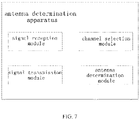
- the apparatus includes: a signal reception module configured to acquire received signals of two antennas; a channel selection module configured to compare signal quality of the received signals with a first signal quality threshold respectively, and select a channel corresponding to the received signal with signal quality greater than the first signal quality threshold as a communication channel; and an antenna determination module configured to determine an antenna corresponding to the communication channel.
- an embodiment provides a terminal device.
- the terminal device is configured to perform the antenna determination method described above.
- an embodiment provides an electronic device.
- the electronic device includes: a memory, configured to store a computer program which is able to implement the method described above, and a processor which, when executing the computer program, implements the method described above.
- an embodiment provides a computer-readable storage medium, storing computer executable instructions for performing the method described above.
- V2X resources there are two modes to allocate V2X resources: one mode is scheduling resources by an evolved Node B (eNB), and the other mode is selecting resources by User Equipment (LTE) independently.
- eNB evolved Node B
- LTE User Equipment
- the V2X direct link communication based on the mode of selecting resources by UE independently does not need to occupy resources of the eNB, but the communication latency and communication quality still cannot meet the requirements. Therefore, it is urgent to achieve a communication mode with lower latency and higher reliability to reduce resource congestion and conflict.
- an antenna determination method and apparatus a vehicle networking terminal device, an electronic device and a storage medium are provided.
- the antenna determination method and device, the vehicle networking terminal device, the electronic device and the storage medium on the premise of establishing communication connection with an opposite terminal device, by means of comparing the quality of received signals of at least two antennas, selecting a channel corresponding to the signal with better signal quality as a communication channel, and switching to the antenna corresponding to the communication channel for subsequent signal transmission and reception, can effectively reduce the communication latency, improve the communication quality, and share obtained vehicle speed, direction, geographic location, route and other important information with other terminal devices in the vehicle network in a timely and effective manner in the V2X direct link communication based on the mode of selecting resources by UE independently.
- FIG. 1 is a flowchart of the antenna determination method according to an embodiment of the present disclosure. As shown in FIG. 1 , the antenna determination method according to this embodiment at least includes steps S100 to S400.
- a communication connection is established with a second terminal device.
- the antenna determination method in this embodiment is applicable to a first terminal device. Therefore, in this step, the first terminal device first establishes a communication connection with the second terminal device.
- the method for establishing communication connection may include: sending, by the first terminal device, connection information to the second terminal device through an antenna, and using, by the second terminal device, one or more antennas to receive data and realize communication connection with the first terminal device; or, sending, by the second terminal device, connection information to the first terminal device through an antenna and using, by the first terminal device, one or more antennas to receive data and realize communication connection with the second terminal device.
- received signal of the first antenna and received signal of the second antenna are acquired.
- the first terminal device has at least two antennas, that is, the first terminal device may have three antennas, four antennas or even more. These antennas are preferably oriented in different directions, so as to be more accurate and sensitive to signals transmitted in different directions. As those having ordinary skills in the art know, these antennas may be directional antennas or antenna arrays. In combination with the beamforming technology of directional antennas, these antennas oriented in different directions can achieve low latency and high quality of communication.
- the second terminal device After the communication connection is established, the second terminal device transmits through its antenna a reference signal to the first terminal device, and the reference signal is used for subsequent evaluation of channel quality.
- the second terminal device has four antennas, so that the second terminal device sends reference signals to the first terminal device through the four antennas.
- the second terminal device transmits reference signals through four antennas in a determined time period, and the four antennas transmit signals at intervals. Transmitting signals through different antennas at different times can avoid mutual interference between antenna signals, allowing subsequent evaluation of channel quality to be more accurate.
- the first terminal device receives the reference signals transmitted by the second terminal device through more than two antennas, that is, for the first terminal device, the first terminal device acquires the received signal of the first antenna and the received signal of the second antenna.
- the received signals are the reference signals.
- the first terminal device corresponding to the second terminal device with four antennas, also has four antennas, and the four antennas of the first terminal device respectively receive reference signals from the four antennas of the second terminal device.
- the quality of the received signals are compared with a first signal quality threshold, and a channel corresponding to the received signal with signal quality greater than the first signal quality threshold is selected as a communication channel.
- the first terminal device has at least a first antenna and a second antenna, so that at least two channels of received signals may be obtained, and then the signal quality of each received signal is calculated separately, where the signal quality of the received signal may have an evaluation parameter including a reference signal reception power, a signal to interference plus noise ratio, a received signal strength indication, a reference signal reception quality, and so on.
- the signal quality can be evaluated through multiple dimensions and methods. Therefore, any parameters and methods that can be used to evaluate the signal quality are within the protection scope of S300 of the embodiment of the present disclosure.
- the reference signal reception power is used as an evaluation index of signal quality, that is, the higher the reference signal reception power of the received signal is, the higher the signal quality is.
- the signal with required signal quality and a corresponding channel are selected.
- the channel corresponding to the signal can be used as a transmission channel, where there may be one or more transmission channels.
- the channel corresponding to the signal with the best signal quality is selected as the transmission channel.
- the antenna corresponding to the communication channel is determined as an operating antenna of the terminal device.
- the first terminal device After determining the communication channel, the first terminal device selects the antenna corresponding to the communication channel as an antenna for subsequent transmission and reception, that is, the first terminal device will switch to the antenna corresponding to the communication channel.
- the first terminal device using the antenna determination method should have at least two antennas, while the second terminal device sending reference signals to the first terminal device may have one or more antennas. Meanwhile, there may be one or more transmission antennas obtained by the antenna determination method, as the terminal device may use multiple antennas to transmit at the same time in the actual operating state.
- the antenna determination method on the premise of establishing communication connection with an opposite terminal device, by means of comparing the quality of the received signals of at least two antennas, selecting the channel corresponding to the signal with better signal quality as the communication channel, and switching to the antenna corresponding to the communication channel for subsequent signal transmission and reception, can effectively reduce the communication latency, improve the communication quality, and share obtained vehicle speed, direction, geographic location, route and other important information with other terminal devices in a timely and effective manner in the V2X direct link communication based on the mode of selecting resources by UE independently .
- FIG 2 is a schematic diagram of a terminal system according to an embodiment of the present disclosure.
- the terminal system includes a first terminal device shown on the left and a second terminal device shown on the right.
- the first terminal device has a transmission/reception module that can support both transmission and reception, and three reception modules.
- the four modules are connected to four antennas through a 4P4T multi-pole multi-throw RF switch.
- the second terminal device also has a transmission/reception module that can support both transmission and reception, and three reception modules.
- the four modules are connected to four antennas through a 4P4T multi-pole multi-throw RF switch.
- FIG 3 The flowchart of an antenna determination method of the terminal system according to this embodiment is shown in FIG 3 , which includes at least the following steps S101 to S104.
- the first terminal device uses a first antenna to send a connection signal to the second terminal device, and establishes a communication connection with the second terminal device.
- the first terminal device sends connection information to the second terminal device through an antenna
- the second terminal device uses one or more antennas to receive data and realize communication connection with the first terminal device.
- the reception modules of the first terminal device stop operating, and the transmission module transmits reference signals from the first antenna, a second antenna, a third antenna and a fourth antenna to the second terminal device respectively in a first time period.
- the second terminal device has four antennas, so the first terminal device transmits reference signals to the second terminal device periodically through the four antennas respectively, that is, transmits reference signals to the second terminal device from the first antenna, the second antenna, the third antenna and the fourth antenna respectively within a determined time period.
- the second terminal device corresponding to the first terminal device with four antennas, also has four antennas, and the four antennas of the second terminal device respectively receive reference signals from the four antennas of the second terminal device.
- the second terminal device performs channel estimation through the received signals of the four reception modules, and determines the channel quality of the transmission channels from the first terminal device to the second terminal device through the reference signal reception power.
- the reference signal reception power is used as an evaluation index of signal quality, that is, the higher the reference signal reception power of the received signal is, the higher the signal quality is.
- the second terminal device uses the antenna corresponding to the channel with the best signal quality as the antenna for subsequent communication with the first terminal device.
- the channel corresponding to the received signal with the maximum reference signal reception power is used as the communication channel, and the second terminal device uses the antenna corresponding to the communication channel as an operating antenna.
- the second terminal device has switched to the antenna that can communicate with the first terminal device and has good channel quality. Prior to the next execution of the antenna switching scheme, the second terminal device will use this antenna to communicate with the first terminal device.
- the first terminal device in order to switch to an antenna that can communicate with the second terminal device and has good channel quality, the first terminal device also repeats the above steps S101 to S 104.
- the terminal system on the premise of establishing communication connection with an opposite terminal device, by means of comparing the quality of the received signals of at least two antennas, selecting the channel corresponding to the signal with better signal quality as the communication channel, and switching to the antenna corresponding to the communication channel for subsequent signal transmission and reception, can effectively reduce the communication latency, improve the communication quality, and share obtained vehicle speed, direction, geographic location, route and other important information with other terminal devices in a timely and effective manner in the V2X direct link communication based on the mode of selecting resources by UE independently.
- FIG 4 is a schematic diagram of a V2X terminal device according to another embodiment of the present disclosure.
- FIG 4 shows one V2X terminal device, which is a vehicle terminal device.
- the vehicle terminal device includes two transmission/reception modules that can support both transmission and reception, which are a first transmission/reception module and a second transmission/reception module, and two reception modules.
- the two transmission/reception modules are connected to different switches.
- a first antenna is connected to a first switch
- a second antenna and a third antenna are respectively connected to a second switch
- a fourth antenna is connected to a third switch.
- the three switches are single-pole three-throw switches or three-pole three-throw switches, which are used to select an antenna and a corresponding module that meet the requirements.
- FIG 5 The flowchart of an antenna determination method of the V2X terminal device according to this embodiment is shown in FIG 5 , which at least includes the following steps S201 to S207.
- the vehicle terminal device uses the first antenna to send a connection signal to a roadside unit (RSU), and establishes a communication connection with the RSU.
- RSU roadside unit
- the reception modules of the vehicle terminal device stop operating, and a first transmission module transmits reference signals from the first antenna, the second antenna, the third antenna and the fourth antenna to the RSU respectively in a first time period.
- the RSU performs channel estimation through received signals of the four reception modules, and determines channel quality of transmission channels from the vehicle terminal device to the RSU through reference signal reception power.
- the RSU determines the antenna corresponding to the channel with the best signal quality as a first transceiver antenna for subsequent communication with the vehicle terminal device.
- the reception modules of the vehicle terminal device continue to stop operating, and the second transmission module transmits reference signals from the first antenna, the second antenna, the third antenna and the fourth antenna to the RSU respectively in a second time period.
- the RSU performs channel estimation through the received signals of the four reception modules, and determines the channel quality of the transmission channels from the vehicle terminal device to the RSU through the reference signal reception power.
- the RSU uses the antenna corresponding to the channel with the best signal quality as a second transmission antenna for subsequent communication with the vehicle terminal device.
- the above steps S201 to S204 are the transmission process of the reference signals of the vehicle terminal device based on the first transmission module, and the RSU on the opposite side determines the best antenna, i.e., the first communication antenna, that can communicate with the antenna supported by the first transmission module of the vehicle terminal device, by receiving, calculating and comparing the above reference signals using at least two antennas.
- Steps S205 to S207 are basically the same as steps S202 to S204. The only difference lies in that the above steps are the transmission process of the reference signals of the vehicle terminal device based on the second transmission module, and the RSU on the opposite side determines the best antenna i.e., the second transceiver antenna, that can communicate with the antenna supported by the second transmission module of the vehicle terminal device, by receiving, calculating and comparing the above reference signals using at least two antennas.
- vehicle terminal devices, roadside units, mobile phones and other fixed or mobile terminal devices in V2V, V2N, V2P and V2I systems can all use the antenna determination method according to the above embodiments, and be adaptively configured with terminal structures adapted to the above antenna determination method.
- the terminal device based on the Internet of Vehicles is always moving. Therefore, when the terminal device detects that the quality of the received signals has significantly decreased or is less than a preset second signal quality threshold, the antenna determination method will be re-executed to use the antenna corresponding to the channel with the best quality for real-time transmission and reception.
- the terminal system on the premise of establishing communication connection with an opposite terminal device, by means of comparing the quality of the received signals of at least two antennas, selecting the channel corresponding to the signal with better signal quality as the communication channel, and switching to the antenna corresponding to the communication channel for subsequent signal transmission and reception, can effectively reduce the communication latency, improve the communication quality, and share obtained vehicle speed, direction, geographic location, route and other important information with other terminal devices in the vehicle network in a timely and effective manner in the V2X direct link communication based on the mode of selecting resources by UE independently.
- FIG 6 is a schematic diagram of the V2X system terminal device according to another embodiment of the present disclosure.
- the second terminal device and the third terminal device can communicate with each other by means of the first terminal device.
- the first terminal device serves as a base station for resource allocation.
- the vehicle terminal device shown in the center of the figure has four antennas oriented forward, backward, left and right. Based on the antenna determination method according to the above embodiments, an antenna oriented to the left may be used when the vehicle terminal device communicates with a vehicle terminal device on the left. Similarly, an antenna oriented to the right may be used when the vehicle terminal device communicates with a roadside unit on the right.
- the above antennas can ensure the best communication quality and the minimum latency.
- the vehicle terminal device realizes communication with the vehicle terminal device on the left and communication with the roadside unit on the right, the vehicle terminal device can be used as a base station to realize communication between the vehicle terminal device on the left and the roadside unit on the right.
- an embodiment provides an antenna determination apparatus.
- the apparatus includes: a signal reception module configured to acquire received signals of two antennas; a channel selection module configured to compare signal quality of the received signals with a first signal quality threshold respectively, and select a channel corresponding to the received signal with signal quality greater than the first signal quality threshold as a communication channel; and an antenna determination module configured to determine an antenna corresponding to the communication channel.
- the antenna switching device further includes a signal transmission module, which is configured to transmit signals through the antenna corresponding to the transmission channel.
- an embodiment provides a terminal device.
- the terminal device performs the antenna determination method described above.
- an embodiment provides an electronic device.
- the device includes: a processor, and a memory configured to store a computer program which, when executed by the processor, causes the processor to implement the method described above.
- an embodiment provides a computer-readable storage medium, storing computer executable instructions which, when executed by a processor, cause the processor to implement the method described above.
- the embodiments of the present disclosure on the premise of establishing communication connection with an opposite terminal device, by means of comparing the quality of the received signals of at least two antennas, selecting the channel corresponding to the signal with better signal quality as the communication channel, and switching to the antenna corresponding to the communication channel for subsequent signal transmission and reception, can effectively reduce the communication latency, improve the communication quality, and share obtained vehicle speed, direction, geographic location, route and other important information with other terminal devices in a timely and effective manner in the V2X direct link communication based on the mode of selecting resources by UE independently.
- the device embodiments described above are only illustrative, in which the units described as separated components may be or may not be physically separated, that is, they may be located in one place or distributed across multiple network units. Some or all of the modules can be selected according to actual needs to achieve the purpose of the embodiments.
- a physical component may have multiple functions, or a function or step may be performed jointly by several physical components.
- Some or all of the physical components may be implemented as software executed by a processor, such as a central processor, a digital signal processor, or a microprocessor, or as hardware, or as an integrated circuit, such as an application specific integrated circuit.
- Such software may be distributed on a computer-readable medium, which may include a computer storage medium (or a non-temporary medium) and a communication medium (or a temporary medium).
- a computer storage medium or a non-temporary medium
- a communication medium or a temporary medium
- the term computer storage medium includes volatile and nonvolatile, removable and non-removable media implemented in any method or technology for storing information, such as computer-readable instructions, data structures, program modules, or other data.
- a computer storage medium may include, but not limited to, a random access memory (RAM), a read-only memory (ROM), an electrically erasable programmable read-only memory (EEPROM), a flash memory or other memory technology, a compact disc read-only memory (CD-ROM), a digital versatile disc (DVD) or other optical storage, a cassette, a magnetic tape, a magnetic disk storage or other magnetic storage device, or any other medium which can be used to store the desired information and which can be accessed by a computer.
- the communication medium typically includes computer-readable instructions, data structures, program modules, or other data in a modulated data signal such as a carrier wave or other transport mechanism, and may include any information passing medium.
- the terminal device may be all terminal devices in the vehicle network system, including vehicle terminal devices, roadside units, etc., or mobile phones, tablets, laptops, handheld computers, vehicle terminal device, wearable devices, super mobile personal computers, netbooks, personal digital assistants, CPE, UFI (wireless hotspot devices), and the like in non-vehicle network systems, which is not specifically limited in the implementations of the present disclosure.
Abstract
Description
- This application is filed on the basis of
Chinese patent application No. 202010600466.0 filed June 28, 2020 - The embodiments of the present disclosure relate to, but not limited to, the field of communication, and in particular to an antenna determination method and apparatus, a terminal device, an electronic device and a storage medium.
- Vehicle-to-Everything Communications (V2X for short) refers to providing vehicle information through sensors, vehicle terminal devices and electronic tags provided on vehicles, and using various communication technologies to achieve Vehicle-to-Vehicle Communication (V2V for short), Vehicle-to-Pedestrian Communications (V2P for short), Vehicle-to-Infrastructure Communications (V2I for short), Vehicle-to-Network Communications (V2N for short), and effectively using such as extracting, sharing, etc., information on the information network platform to effectively control vehicles and provide comprehensive services.
- Currently, there are two modes to allocate V2X resources: one mode is scheduling resources by an evolved Node B (eNB), and the other mode is selecting resources by User Equipment (UE) independently. The V2X direct link communication based on the mode of selecting resources by UE independently does not need to occupy the resources of the eNB, but the communication latency and communication quality still cannot meet the requirements. Therefore, it is urgent to achieve a communication mode with lower latency and higher reliability to reduce resource congestion and conflict.
- The following is a summary of the subjects detailed herein. This summary is not intended to limit the scope of protection of the claims.
- According to some embodiments of the present disclosure, an antenna determination method and apparatus, a terminal device, an electronic device and a storage medium are provided.
- In accordance with an aspect of the present disclosure, an embodiment provides an antenna determination method, which is applicable to a terminal device. The terminal device at least includes two antennas. The method includes: acquiring received signals of the two antennas; comparing signal quality of the received signals of the two antennas with a first signal quality threshold respectively, and selecting a channel corresponding to the received signal with signal quality greater than the first signal quality threshold as a communication channel; and determining an antenna corresponding to the communication channel as an operating antenna of the terminal device.
- In accordance with another aspect of the present disclosure, an embodiment provides an antenna determination apparatus. The apparatus includes: a signal reception module configured to acquire received signals of two antennas; a channel selection module configured to compare signal quality of the received signals with a first signal quality threshold respectively, and select a channel corresponding to the received signal with signal quality greater than the first signal quality threshold as a communication channel; and an antenna determination module configured to determine an antenna corresponding to the communication channel.
- In accordance with another aspect of the present disclosure, an embodiment provides a terminal device. The terminal device is configured to perform the antenna determination method described above.
- In accordance with another aspect of the present disclosure, an embodiment provides an electronic device. The electronic device includes: a memory, configured to store a computer program which is able to implement the method described above, and a processor which, when executing the computer program, implements the method described above.
- In accordance with another aspect of the present disclosure, an embodiment provides a computer-readable storage medium, storing computer executable instructions for performing the method described above.
- Other features and advantages of the present disclosure will be set forth in the subsequent description, and will become apparent in part from the description, or will be understood by implementing the present disclosure. The object and other advantages of the present disclosure can be realized and obtained by the structures specially pointed out in the description, the claims and the drawings.
-
-
FIG 1 is a flowchart of an antenna determination method according to an embodiment of the present disclosure; -
FIG 2 is a schematic diagram of a terminal system according to an embodiment of the present disclosure; -
FIG 3 is a flowchart of an antenna determination method based on a terminal system according to an embodiment of the present disclosure; -
FIG 4 is a schematic diagram of a V2X terminal device according to another embodiment of the present disclosure; -
FIG. 5 is a flowchart of an antenna determination method based on a V2X terminal device according to another embodiment of the present disclosure; -
FIG 6 is a schematic diagram of a V2X terminal device according to another embodiment of the present disclosure; and -
FIG 7 is a module diagram of the terminal device according to another embodiment of the present disclosure. - In order to make the purpose, technical scheme and advantages of the present disclosure clear, the present disclosure is further described in detail below in combination with the drawings and embodiments. It should be understood that the specific embodiments described herein are only used to illustrate the present disclosure, and are not intended to limit the present disclosure.
- It is to be noted, although functional modules have been divided in the schematic diagrams of devices and logical orders have been shown in the flowcharts, in some cases, the modules may be divided in a different manner, or the steps shown or described may be executed in an order different from the orders as shown in the flowcharts. The terms such as "first", "second" and the like in the description, the claims, and the accompanying drawings are used to distinguish between similar objects, and are not necessarily used to describe a specific sequence or a precedence order.
- In the description of the embodiments of the present disclosure, unless otherwise specified, the words such as setting, installation, connection, and the like should be understood in a broad sense, and those having ordinary skills in the art can reasonably determine the specific meaning of the above terms in the embodiments of the present disclosure in combination with the specific content of the technical scheme.
- Currently, there are two modes to allocate V2X resources: one mode is scheduling resources by an evolved Node B (eNB), and the other mode is selecting resources by User Equipment (LTE) independently. The V2X direct link communication based on the mode of selecting resources by UE independently does not need to occupy resources of the eNB, but the communication latency and communication quality still cannot meet the requirements. Therefore, it is urgent to achieve a communication mode with lower latency and higher reliability to reduce resource congestion and conflict.
- In view of the above, according to some embodiments of the present disclosure, an antenna determination method and apparatus, a vehicle networking terminal device, an electronic device and a storage medium are provided. The antenna determination method and device, the vehicle networking terminal device, the electronic device and the storage medium, on the premise of establishing communication connection with an opposite terminal device, by means of comparing the quality of received signals of at least two antennas, selecting a channel corresponding to the signal with better signal quality as a communication channel, and switching to the antenna corresponding to the communication channel for subsequent signal transmission and reception, can effectively reduce the communication latency, improve the communication quality, and share obtained vehicle speed, direction, geographic location, route and other important information with other terminal devices in the vehicle network in a timely and effective manner in the V2X direct link communication based on the mode of selecting resources by UE independently.
- The embodiments of the present disclosure are further described below in combination with the accompanying drawings.
- In accordance with an aspect of the present disclosure, an embodiment provides an antenna determination method.
FIG. 1 is a flowchart of the antenna determination method according to an embodiment of the present disclosure. As shown inFIG. 1 , the antenna determination method according to this embodiment at least includes steps S100 to S400. - At
S 100, a communication connection is established with a second terminal device. - The antenna determination method in this embodiment is applicable to a first terminal device. Therefore, in this step, the first terminal device first establishes a communication connection with the second terminal device. The method for establishing communication connection may include: sending, by the first terminal device, connection information to the second terminal device through an antenna, and using, by the second terminal device, one or more antennas to receive data and realize communication connection with the first terminal device; or, sending, by the second terminal device, connection information to the first terminal device through an antenna and using, by the first terminal device, one or more antennas to receive data and realize communication connection with the second terminal device.
- At S200, received signal of the first antenna and received signal of the second antenna are acquired.
- It is worth noting that the first terminal device has at least two antennas, that is, the first terminal device may have three antennas, four antennas or even more. These antennas are preferably oriented in different directions, so as to be more accurate and sensitive to signals transmitted in different directions. As those having ordinary skills in the art know, these antennas may be directional antennas or antenna arrays. In combination with the beamforming technology of directional antennas, these antennas oriented in different directions can achieve low latency and high quality of communication.
- After the communication connection is established, the second terminal device transmits through its antenna a reference signal to the first terminal device, and the reference signal is used for subsequent evaluation of channel quality.
- In an embodiment, the second terminal device has four antennas, so that the second terminal device sends reference signals to the first terminal device through the four antennas.
- In some examples, the second terminal device transmits reference signals through four antennas in a determined time period, and the four antennas transmit signals at intervals. Transmitting signals through different antennas at different times can avoid mutual interference between antenna signals, allowing subsequent evaluation of channel quality to be more accurate.
- The first terminal device receives the reference signals transmitted by the second terminal device through more than two antennas, that is, for the first terminal device, the first terminal device acquires the received signal of the first antenna and the received signal of the second antenna. Here, the received signals are the reference signals.
- In an embodiment, corresponding to the second terminal device with four antennas, the first terminal device also has four antennas, and the four antennas of the first terminal device respectively receive reference signals from the four antennas of the second terminal device.
- At S300, the quality of the received signals are compared with a first signal quality threshold, and a channel corresponding to the received signal with signal quality greater than the first signal quality threshold is selected as a communication channel.
- The first terminal device has at least a first antenna and a second antenna, so that at least two channels of received signals may be obtained, and then the signal quality of each received signal is calculated separately, where the signal quality of the received signal may have an evaluation parameter including a reference signal reception power, a signal to interference plus noise ratio, a received signal strength indication, a reference signal reception quality, and so on. Those having ordinary skills in the art should know that the signal quality can be evaluated through multiple dimensions and methods. Therefore, any parameters and methods that can be used to evaluate the signal quality are within the protection scope of S300 of the embodiment of the present disclosure.
- In an embodiment, the reference signal reception power is used as an evaluation index of signal quality, that is, the higher the reference signal reception power of the received signal is, the higher the signal quality is.
- By presetting a first signal quality threshold in advance, the signal with required signal quality and a corresponding channel are selected.
- In an embodiment, once the signal quality is greater than the first signal quality threshold, the channel corresponding to the signal can be used as a transmission channel, where there may be one or more transmission channels.
- In another embodiment, the channel corresponding to the signal with the best signal quality is selected as the transmission channel.
- At S400, the antenna corresponding to the communication channel is determined as an operating antenna of the terminal device.
- After determining the communication channel, the first terminal device selects the antenna corresponding to the communication channel as an antenna for subsequent transmission and reception, that is, the first terminal device will switch to the antenna corresponding to the communication channel.
- Through the embodiments of the present disclosure, those having ordinary skills in the art should know that the first terminal device using the antenna determination method should have at least two antennas, while the second terminal device sending reference signals to the first terminal device may have one or more antennas. Meanwhile, there may be one or more transmission antennas obtained by the antenna determination method, as the terminal device may use multiple antennas to transmit at the same time in the actual operating state.
- The antenna determination method according to the present embodiment, on the premise of establishing communication connection with an opposite terminal device, by means of comparing the quality of the received signals of at least two antennas, selecting the channel corresponding to the signal with better signal quality as the communication channel, and switching to the antenna corresponding to the communication channel for subsequent signal transmission and reception, can effectively reduce the communication latency, improve the communication quality, and share obtained vehicle speed, direction, geographic location, route and other important information with other terminal devices in a timely and effective manner in the V2X direct link communication based on the mode of selecting resources by UE independently .
-
FIG 2 is a schematic diagram of a terminal system according to an embodiment of the present disclosure. - As shown in
FIG 2 , the terminal system includes a first terminal device shown on the left and a second terminal device shown on the right. The first terminal device has a transmission/reception module that can support both transmission and reception, and three reception modules. The four modules are connected to four antennas through a 4P4T multi-pole multi-throw RF switch. The second terminal device also has a transmission/reception module that can support both transmission and reception, and three reception modules. The four modules are connected to four antennas through a 4P4T multi-pole multi-throw RF switch. - The flowchart of an antenna determination method of the terminal system according to this embodiment is shown in
FIG 3 , which includes at least the following steps S101 to S104. - At S101, the first terminal device uses a first antenna to send a connection signal to the second terminal device, and establishes a communication connection with the second terminal device.
- In this embodiment, the first terminal device sends connection information to the second terminal device through an antenna, and the second terminal device uses one or more antennas to receive data and realize communication connection with the first terminal device.
- At S102, the reception modules of the first terminal device stop operating, and the transmission module transmits reference signals from the first antenna, a second antenna, a third antenna and a fourth antenna to the second terminal device respectively in a first time period.
- In this embodiment, the second terminal device has four antennas, so the first terminal device transmits reference signals to the second terminal device periodically through the four antennas respectively, that is, transmits reference signals to the second terminal device from the first antenna, the second antenna, the third antenna and the fourth antenna respectively within a determined time period.
- In this embodiment, corresponding to the first terminal device with four antennas, the second terminal device also has four antennas, and the four antennas of the second terminal device respectively receive reference signals from the four antennas of the second terminal device.
- At S103, the second terminal device performs channel estimation through the received signals of the four reception modules, and determines the channel quality of the transmission channels from the first terminal device to the second terminal device through the reference signal reception power.
- In this embodiment, the reference signal reception power is used as an evaluation index of signal quality, that is, the higher the reference signal reception power of the received signal is, the higher the signal quality is.
- At S104, the second terminal device uses the antenna corresponding to the channel with the best signal quality as the antenna for subsequent communication with the first terminal device.
- In this embodiment, based on the calculation of the reference signal reception power of each received signal, the channel corresponding to the received signal with the maximum reference signal reception power is used as the communication channel, and the second terminal device uses the antenna corresponding to the communication channel as an operating antenna.
- Through the above steps, the second terminal device has switched to the antenna that can communicate with the first terminal device and has good channel quality. Prior to the next execution of the antenna switching scheme, the second terminal device will use this antenna to communicate with the first terminal device.
- Correspondingly, in order to switch to an antenna that can communicate with the second terminal device and has good channel quality, the first terminal device also repeats the above steps S101 to
S 104. - The terminal system according to the present embodiment, on the premise of establishing communication connection with an opposite terminal device, by means of comparing the quality of the received signals of at least two antennas, selecting the channel corresponding to the signal with better signal quality as the communication channel, and switching to the antenna corresponding to the communication channel for subsequent signal transmission and reception, can effectively reduce the communication latency, improve the communication quality, and share obtained vehicle speed, direction, geographic location, route and other important information with other terminal devices in a timely and effective manner in the V2X direct link communication based on the mode of selecting resources by UE independently.
-
FIG 4 is a schematic diagram of a V2X terminal device according to another embodiment of the present disclosure.FIG 4 shows one V2X terminal device, which is a vehicle terminal device. The vehicle terminal device includes two transmission/reception modules that can support both transmission and reception, which are a first transmission/reception module and a second transmission/reception module, and two reception modules. As the reception and transmission of signals between the above transmission/reception modules will interfere with each other, the two transmission/reception modules are connected to different switches. A first antenna is connected to a first switch, a second antenna and a third antenna are respectively connected to a second switch, and a fourth antenna is connected to a third switch. The three switches are single-pole three-throw switches or three-pole three-throw switches, which are used to select an antenna and a corresponding module that meet the requirements. - The flowchart of an antenna determination method of the V2X terminal device according to this embodiment is shown in
FIG 5 , which at least includes the following steps S201 to S207. - At 5201, the vehicle terminal device uses the first antenna to send a connection signal to a roadside unit (RSU), and establishes a communication connection with the RSU.
- At S202, the reception modules of the vehicle terminal device stop operating, and a first transmission module transmits reference signals from the first antenna, the second antenna, the third antenna and the fourth antenna to the RSU respectively in a first time period.
- At S203, the RSU performs channel estimation through received signals of the four reception modules, and determines channel quality of transmission channels from the vehicle terminal device to the RSU through reference signal reception power.
- At S204, the RSU determines the antenna corresponding to the channel with the best signal quality as a first transceiver antenna for subsequent communication with the vehicle terminal device.
- At S205, the reception modules of the vehicle terminal device continue to stop operating, and the second transmission module transmits reference signals from the first antenna, the second antenna, the third antenna and the fourth antenna to the RSU respectively in a second time period.
- At S206, the RSU performs channel estimation through the received signals of the four reception modules, and determines the channel quality of the transmission channels from the vehicle terminal device to the RSU through the reference signal reception power.
- At S207, the RSU uses the antenna corresponding to the channel with the best signal quality as a second transmission antenna for subsequent communication with the vehicle terminal device.
- The above steps S201 to S204 are the transmission process of the reference signals of the vehicle terminal device based on the first transmission module, and the RSU on the opposite side determines the best antenna, i.e., the first communication antenna, that can communicate with the antenna supported by the first transmission module of the vehicle terminal device, by receiving, calculating and comparing the above reference signals using at least two antennas.
- Steps S205 to S207 are basically the same as steps S202 to S204. The only difference lies in that the above steps are the transmission process of the reference signals of the vehicle terminal device based on the second transmission module, and the RSU on the opposite side determines the best antenna i.e., the second transceiver antenna, that can communicate with the antenna supported by the second transmission module of the vehicle terminal device, by receiving, calculating and comparing the above reference signals using at least two antennas.
- As those having ordinary skills in the art know, vehicle terminal devices, roadside units, mobile phones and other fixed or mobile terminal devices in V2V, V2N, V2P and V2I systems can all use the antenna determination method according to the above embodiments, and be adaptively configured with terminal structures adapted to the above antenna determination method.
- Meanwhile, the terminal device based on the Internet of Vehicles is always moving. Therefore, when the terminal device detects that the quality of the received signals has significantly decreased or is less than a preset second signal quality threshold, the antenna determination method will be re-executed to use the antenna corresponding to the channel with the best quality for real-time transmission and reception.
- The terminal system according to the present embodiment, on the premise of establishing communication connection with an opposite terminal device, by means of comparing the quality of the received signals of at least two antennas, selecting the channel corresponding to the signal with better signal quality as the communication channel, and switching to the antenna corresponding to the communication channel for subsequent signal transmission and reception, can effectively reduce the communication latency, improve the communication quality, and share obtained vehicle speed, direction, geographic location, route and other important information with other terminal devices in the vehicle network in a timely and effective manner in the V2X direct link communication based on the mode of selecting resources by UE independently.
-
FIG 6 is a schematic diagram of the V2X system terminal device according to another embodiment of the present disclosure. - Those having ordinary skills in the art should also know that after both the first terminal device and the second terminal device achieve high quality and low latency communication by utilizing the antenna determination method according to the above embodiments, and after the first terminal device and a third terminal device also achieve high quality and low latency communication by utilizing the antenna determination method according to the above embodiments, the second terminal device and the third terminal device can communicate with each other by means of the first terminal device. At this time, the first terminal device serves as a base station for resource allocation.
- When the second terminal device and the third terminal device are far away from each other and cannot directly communicate with each other through the direct link, this indirect communication mode can solve this problem.
- In this embodiment, the vehicle terminal device shown in the center of the figure has four antennas oriented forward, backward, left and right. Based on the antenna determination method according to the above embodiments, an antenna oriented to the left may be used when the vehicle terminal device communicates with a vehicle terminal device on the left. Similarly, an antenna oriented to the right may be used when the vehicle terminal device communicates with a roadside unit on the right. The above antennas can ensure the best communication quality and the minimum latency. When the vehicle terminal device realizes communication with the vehicle terminal device on the left and communication with the roadside unit on the right, the vehicle terminal device can be used as a base station to realize communication between the vehicle terminal device on the left and the roadside unit on the right.
- In accordance with an aspect of the present disclosure, an embodiment provides an antenna determination apparatus. The apparatus includes: a signal reception module configured to acquire received signals of two antennas; a channel selection module configured to compare signal quality of the received signals with a first signal quality threshold respectively, and select a channel corresponding to the received signal with signal quality greater than the first signal quality threshold as a communication channel; and an antenna determination module configured to determine an antenna corresponding to the communication channel. The antenna switching device further includes a signal transmission module, which is configured to transmit signals through the antenna corresponding to the transmission channel.
- In accordance with another aspect of the present disclosure, an embodiment provides a terminal device. The terminal device performs the antenna determination method described above.
- In accordance with another aspect of the present disclosure, an embodiment provides an electronic device. The device includes: a processor, and a memory configured to store a computer program which, when executed by the processor, causes the processor to implement the method described above.
- In accordance with another aspect of the present disclosure, an embodiment provides a computer-readable storage medium, storing computer executable instructions which, when executed by a processor, cause the processor to implement the method described above.
- The embodiments of the present disclosure, on the premise of establishing communication connection with an opposite terminal device, by means of comparing the quality of the received signals of at least two antennas, selecting the channel corresponding to the signal with better signal quality as the communication channel, and switching to the antenna corresponding to the communication channel for subsequent signal transmission and reception, can effectively reduce the communication latency, improve the communication quality, and share obtained vehicle speed, direction, geographic location, route and other important information with other terminal devices in a timely and effective manner in the V2X direct link communication based on the mode of selecting resources by UE independently.
- The device embodiments described above are only illustrative, in which the units described as separated components may be or may not be physically separated, that is, they may be located in one place or distributed across multiple network units. Some or all of the modules can be selected according to actual needs to achieve the purpose of the embodiments.
- Those having ordinary skills in the art can understand that all or some of the steps in the method, systems, and functional modules in the device disclosed above may be implemented as software, firmware, hardware, and appropriate combinations thereof. In the hardware implementation, the division between functional modules/units mentioned in the above description does not necessarily correspond to the division of physical components. For example, a physical component may have multiple functions, or a function or step may be performed jointly by several physical components. Some or all of the physical components may be implemented as software executed by a processor, such as a central processor, a digital signal processor, or a microprocessor, or as hardware, or as an integrated circuit, such as an application specific integrated circuit. Such software may be distributed on a computer-readable medium, which may include a computer storage medium (or a non-temporary medium) and a communication medium (or a temporary medium). As is well known to those having ordinary skills in the art, the term computer storage medium includes volatile and nonvolatile, removable and non-removable media implemented in any method or technology for storing information, such as computer-readable instructions, data structures, program modules, or other data. A computer storage medium may include, but not limited to, a random access memory (RAM), a read-only memory (ROM), an electrically erasable programmable read-only memory (EEPROM), a flash memory or other memory technology, a compact disc read-only memory (CD-ROM), a digital versatile disc (DVD) or other optical storage, a cassette, a magnetic tape, a magnetic disk storage or other magnetic storage device, or any other medium which can be used to store the desired information and which can be accessed by a computer. In addition, as is known to those having ordinary skills in the art, the communication medium typically includes computer-readable instructions, data structures, program modules, or other data in a modulated data signal such as a carrier wave or other transport mechanism, and may include any information passing medium. The terminal device may be all terminal devices in the vehicle network system, including vehicle terminal devices, roadside units, etc., or mobile phones, tablets, laptops, handheld computers, vehicle terminal device, wearable devices, super mobile personal computers, netbooks, personal digital assistants, CPE, UFI (wireless hotspot devices), and the like in non-vehicle network systems, which is not specifically limited in the implementations of the present disclosure.
- The above describes some embodiments of the present disclosure, but the present disclosure is not limited thereto. Those having ordinary skills in the art can also make various equivalent deformations or substitutions without violating the scope of the present disclosure. These equivalent deformations or substitutions are included in the scope defined by the claims of the present disclosure.
Claims (11)
- An antenna determination method, which is applicable to a terminal device comprising at least two antennas, the method comprising:acquiring received signals of two antennas respectively;comparing signal quality of the received signals of the two antennas with a first signal quality threshold respectively, and selecting a channel corresponding to the received signal with signal quality greater than the first signal quality threshold as a communication channel; anddetermining an antenna corresponding to the communication channel as an operating antenna of the terminal device.
- The method of claim 1, wherein comparing signal quality of the received signals of the two antennas with a first signal quality threshold respectively, and selecting a channel corresponding to the received signal with signal quality greater than the first signal quality threshold as a communication channel, comprises:
selecting a channel corresponding to the received signal with best signal quality as the communication channel. - The method of claim 1, wherein the received signals of the two antennas are received at an interval.
- The method of claim 1, wherein the signal quality has an evaluation parameter comprising at least one of:
a reference signal receiving power, a signal to interference plus noise ratio, a received signal strength indication, or a reference signal receiving quality. - The method of any one of claims 1 to 4, wherein the two antennas are directional antennas with different orientations.
- An antenna determination apparatus, comprising:a signal reception module, configured to acquire received signals of two antennas respectively;a channel selection module, configured to compare signal quality of the received signals with a first signal quality threshold respectively, and select a channel corresponding to the received signal with signal quality greater than the first signal quality threshold as a communication channel; andan antenna determination module, configured to determine an antenna corresponding to the communication channel.
- The apparatus of claim 6, further comprising:
a signal transmission module, configured to transmit signals through the antenna corresponding to the communication channel. - The apparatus of any one of claims 6 to 7, wherein the two antennas are directional antennas with different orientations.
- A terminal device, which is configured to perform the antenna determination method of any one of claims 1 to 5.
- An electronic device, comprising:a memory, configured to store a computer program which is able to implement the method of any one of claims 1 to 5, anda processor which, when executing the computer program, implements the method of any one of claims 1 to 5.
- A computer-readable storage medium storing computer executable instructions for performing the method of any one of claims 1 to 5.
Applications Claiming Priority (2)
| Application Number | Priority Date | Filing Date | Title |
|---|---|---|---|
| CN202010600466.0A CN113852924A (en) | 2020-06-28 | 2020-06-28 | Antenna determination method, antenna determination device, terminal, electronic equipment and storage medium |
| PCT/CN2021/100405 WO2022001667A1 (en) | 2020-06-28 | 2021-06-16 | Antenna determination method and apparatus, terminal, electronic device, and storage medium |
Publications (2)
| Publication Number | Publication Date |
|---|---|
| EP4131799A1 true EP4131799A1 (en) | 2023-02-08 |
| EP4131799A4 EP4131799A4 (en) | 2023-09-20 |
Family
ID=78972712
Family Applications (1)
| Application Number | Title | Priority Date | Filing Date |
|---|---|---|---|
| EP21834426.5A Pending EP4131799A4 (en) | 2020-06-28 | 2021-06-16 | Antenna determination method and apparatus, terminal, electronic device, and storage medium |
Country Status (4)
| Country | Link |
|---|---|
| US (1) | US20230224946A1 (en) |
| EP (1) | EP4131799A4 (en) |
| CN (1) | CN113852924A (en) |
| WO (1) | WO2022001667A1 (en) |
Families Citing this family (1)
| Publication number | Priority date | Publication date | Assignee | Title |
|---|---|---|---|---|
| CN116961790A (en) * | 2022-04-19 | 2023-10-27 | 中兴通讯股份有限公司 | Communication signal transmission method and device, electronic equipment and storage medium |
Family Cites Families (8)
| Publication number | Priority date | Publication date | Assignee | Title |
|---|---|---|---|---|
| GB2311693B (en) * | 1996-03-29 | 2000-06-21 | Nokia Mobile Phones Ltd | Antenna selection control circuitry |
| KR100651447B1 (en) * | 2004-04-14 | 2006-11-29 | 삼성전자주식회사 | System and method for reselecting antennas in a cellular mobile communication system using a plurality of antennas |
| US9319125B2 (en) * | 2012-07-19 | 2016-04-19 | Electronics And Telecommunications Research Institute | Method and apparatus of wireless communication by using multiple directional antennas |
| WO2018053876A1 (en) * | 2016-09-26 | 2018-03-29 | 深圳市大疆创新科技有限公司 | Antenna selection method, apparatus and video glasses |
| CN106952480A (en) * | 2017-05-18 | 2017-07-14 | 迈锐数据(北京)有限公司 | A kind of control method of wagon detector and wagon detector |
| JP6900335B2 (en) * | 2018-02-26 | 2021-07-07 | 矢崎総業株式会社 | Integrated antenna module and in-vehicle system |
| CN109273845B (en) * | 2018-10-16 | 2020-10-09 | 东莞华贝电子科技有限公司 | Directional antenna, terminal based on multi-antenna design and method for reducing power consumption |
| KR102573221B1 (en) * | 2018-10-25 | 2023-08-31 | 현대자동차주식회사 | Antenna and vehicle including the same |
-
2020
- 2020-06-28 CN CN202010600466.0A patent/CN113852924A/en active Pending
-
2021
- 2021-06-16 US US17/997,859 patent/US20230224946A1/en active Pending
- 2021-06-16 WO PCT/CN2021/100405 patent/WO2022001667A1/en unknown
- 2021-06-16 EP EP21834426.5A patent/EP4131799A4/en active Pending
Also Published As
| Publication number | Publication date |
|---|---|
| US20230224946A1 (en) | 2023-07-13 |
| CN113852924A (en) | 2021-12-28 |
| EP4131799A4 (en) | 2023-09-20 |
| WO2022001667A1 (en) | 2022-01-06 |
Similar Documents
| Publication | Publication Date | Title |
|---|---|---|
| US11297629B2 (en) | Method and apparatus for carrier aggregation in sidelink communication | |
| US10904826B2 (en) | Methods and systems for autonomous device selection of transmission resources | |
| US8270923B2 (en) | Techniques for receiver beamforming and yielding-threshold adjustments in peer-to-peer networks | |
| CN112399639B (en) | Wireless communication device and wireless communication method thereof | |
| CN111757403B (en) | Resource allocation method and communication device | |
| EP3354048B1 (en) | Speed dependent transmission format for vehicular or d2d transmission | |
| US11533722B2 (en) | Method for transmitting sidelink data and terminal device | |
| CN109804691B (en) | Data transmission method and device and computer storage medium | |
| US11818689B2 (en) | Methods and devices for resource allocation | |
| CN115399027A (en) | Resource reservation method, device, equipment and storage medium | |
| EP3442284B1 (en) | Method and user equipment for resource allocation of vehicle network | |
| EP3955640B1 (en) | Frequency band switching method and apparatus, and terminal device, communication node and computer-readable storage medium | |
| EP4122257A1 (en) | User equipment and method of resource allocation of same | |
| JP2021516479A (en) | Data transmission methods and devices, computer storage media | |
| JP2008141257A (en) | Communication method and radio communication terminal | |
| EP4131799A1 (en) | Antenna determination method and apparatus, terminal, electronic device, and storage medium | |
| US20210274474A1 (en) | Communication device and wireless communication system | |
| AU2018412968B2 (en) | Method for carrier selection in Internet of Vehicles, and terminal device | |
| EP4184842A1 (en) | Signal transmission method and apparatus, node, and storage medium | |
| CN114631392A (en) | Method and apparatus for switching data transmission between radio access technologies for early data transmission | |
| CN115699849A (en) | Wireless communication method and apparatus | |
| CN114600550A (en) | Resource preemption method in sidelink and sidelink equipment | |
| CN109429359B (en) | WLAN link establishment method and equipment | |
| CN117730548A (en) | Information feedback method, device, equipment and storage medium |
Legal Events
| Date | Code | Title | Description |
|---|---|---|---|
| STAA | Information on the status of an ep patent application or granted ep patent |
Free format text: STATUS: THE INTERNATIONAL PUBLICATION HAS BEEN MADE |
|
| PUAI | Public reference made under article 153(3) epc to a published international application that has entered the european phase |
Free format text: ORIGINAL CODE: 0009012 |
|
| STAA | Information on the status of an ep patent application or granted ep patent |
Free format text: STATUS: REQUEST FOR EXAMINATION WAS MADE |
|
| 17P | Request for examination filed |
Effective date: 20221026 |
|
| AK | Designated contracting states |
Kind code of ref document: A1 Designated state(s): AL AT BE BG CH CY CZ DE DK EE ES FI FR GB GR HR HU IE IS IT LI LT LU LV MC MK MT NL NO PL PT RO RS SE SI SK SM TR |
|
| REG | Reference to a national code |
Ref country code: DE Ref legal event code: R079 Free format text: PREVIOUS MAIN CLASS: H04B0007080000 Ipc: H04B0007060000 |
|
| A4 | Supplementary search report drawn up and despatched |
Effective date: 20230821 |
|
| RIC1 | Information provided on ipc code assigned before grant |
Ipc: H04W 92/18 20090101ALN20230814BHEP Ipc: H04W 4/46 20180101ALI20230814BHEP Ipc: H04W 4/44 20180101ALI20230814BHEP Ipc: H04W 4/40 20180101ALI20230814BHEP Ipc: H04B 17/309 20150101ALI20230814BHEP Ipc: H04B 7/08 20060101ALI20230814BHEP Ipc: H04B 7/06 20060101AFI20230814BHEP |
|
| DAV | Request for validation of the european patent (deleted) | ||
| DAX | Request for extension of the european patent (deleted) |