EP4131732A1 - Rotor pour une machine électrique doté d'un orifice élargi de remplissage ou d'aération - Google Patents
Rotor pour une machine électrique doté d'un orifice élargi de remplissage ou d'aération Download PDFInfo
- Publication number
- EP4131732A1 EP4131732A1 EP22186749.2A EP22186749A EP4131732A1 EP 4131732 A1 EP4131732 A1 EP 4131732A1 EP 22186749 A EP22186749 A EP 22186749A EP 4131732 A1 EP4131732 A1 EP 4131732A1
- Authority
- EP
- European Patent Office
- Prior art keywords
- laminated core
- rotor
- opening
- filling opening
- magnets
- Prior art date
- Legal status (The legal status is an assumption and is not a legal conclusion. Google has not performed a legal analysis and makes no representation as to the accuracy of the status listed.)
- Withdrawn
Links
- 238000009423 ventilation Methods 0.000 title claims description 32
- 238000003475 lamination Methods 0.000 claims abstract description 15
- 238000004519 manufacturing process Methods 0.000 claims abstract description 7
- 150000001875 compounds Chemical class 0.000 claims description 50
- 238000005266 casting Methods 0.000 claims description 49
- 238000004382 potting Methods 0.000 claims description 22
- 238000000034 method Methods 0.000 claims description 19
- 238000003780 insertion Methods 0.000 claims description 4
- 230000037431 insertion Effects 0.000 claims description 4
- 238000005429 filling process Methods 0.000 description 3
- 238000004804 winding Methods 0.000 description 3
- 238000005538 encapsulation Methods 0.000 description 2
- 239000003822 epoxy resin Substances 0.000 description 2
- 230000003287 optical effect Effects 0.000 description 2
- 229920000647 polyepoxide Polymers 0.000 description 2
- 230000035484 reaction time Effects 0.000 description 2
- 229910000976 Electrical steel Inorganic materials 0.000 description 1
- 238000009825 accumulation Methods 0.000 description 1
- 239000000853 adhesive Substances 0.000 description 1
- 238000004026 adhesive bonding Methods 0.000 description 1
- 230000001070 adhesive effect Effects 0.000 description 1
- 239000004020 conductor Substances 0.000 description 1
- 238000013461 design Methods 0.000 description 1
- 238000011161 development Methods 0.000 description 1
- 230000000694 effects Effects 0.000 description 1
- 239000000203 mixture Substances 0.000 description 1
- 238000012544 monitoring process Methods 0.000 description 1
- 239000004848 polyfunctional curative Substances 0.000 description 1
- 239000000126 substance Substances 0.000 description 1
- 238000003466 welding Methods 0.000 description 1
Images


Classifications
-
- H—ELECTRICITY
- H02—GENERATION; CONVERSION OR DISTRIBUTION OF ELECTRIC POWER
- H02K—DYNAMO-ELECTRIC MACHINES
- H02K1/00—Details of the magnetic circuit
- H02K1/06—Details of the magnetic circuit characterised by the shape, form or construction
- H02K1/22—Rotating parts of the magnetic circuit
- H02K1/32—Rotating parts of the magnetic circuit with channels or ducts for flow of cooling medium
-
- H—ELECTRICITY
- H02—GENERATION; CONVERSION OR DISTRIBUTION OF ELECTRIC POWER
- H02K—DYNAMO-ELECTRIC MACHINES
- H02K1/00—Details of the magnetic circuit
- H02K1/06—Details of the magnetic circuit characterised by the shape, form or construction
- H02K1/22—Rotating parts of the magnetic circuit
- H02K1/27—Rotor cores with permanent magnets
- H02K1/2706—Inner rotors
- H02K1/272—Inner rotors the magnetisation axis of the magnets being perpendicular to the rotor axis
- H02K1/274—Inner rotors the magnetisation axis of the magnets being perpendicular to the rotor axis the rotor consisting of two or more circumferentially positioned magnets
- H02K1/2753—Inner rotors the magnetisation axis of the magnets being perpendicular to the rotor axis the rotor consisting of two or more circumferentially positioned magnets the rotor consisting of magnets or groups of magnets arranged with alternating polarity
- H02K1/276—Magnets embedded in the magnetic core, e.g. interior permanent magnets [IPM]
-
- H—ELECTRICITY
- H02—GENERATION; CONVERSION OR DISTRIBUTION OF ELECTRIC POWER
- H02K—DYNAMO-ELECTRIC MACHINES
- H02K1/00—Details of the magnetic circuit
- H02K1/06—Details of the magnetic circuit characterised by the shape, form or construction
- H02K1/22—Rotating parts of the magnetic circuit
- H02K1/28—Means for mounting or fastening rotating magnetic parts on to, or to, the rotor structures
-
- H—ELECTRICITY
- H02—GENERATION; CONVERSION OR DISTRIBUTION OF ELECTRIC POWER
- H02K—DYNAMO-ELECTRIC MACHINES
- H02K15/00—Methods or apparatus specially adapted for manufacturing, assembling, maintaining or repairing of dynamo-electric machines
- H02K15/02—Methods or apparatus specially adapted for manufacturing, assembling, maintaining or repairing of dynamo-electric machines of stator or rotor bodies
- H02K15/03—Methods or apparatus specially adapted for manufacturing, assembling, maintaining or repairing of dynamo-electric machines of stator or rotor bodies having permanent magnets
-
- H—ELECTRICITY
- H02—GENERATION; CONVERSION OR DISTRIBUTION OF ELECTRIC POWER
- H02K—DYNAMO-ELECTRIC MACHINES
- H02K9/00—Arrangements for cooling or ventilating
- H02K9/02—Arrangements for cooling or ventilating by ambient air flowing through the machine
-
- H—ELECTRICITY
- H02—GENERATION; CONVERSION OR DISTRIBUTION OF ELECTRIC POWER
- H02K—DYNAMO-ELECTRIC MACHINES
- H02K2213/00—Specific aspects, not otherwise provided for and not covered by codes H02K2201/00 - H02K2211/00
- H02K2213/03—Machines characterised by numerical values, ranges, mathematical expressions or similar information
Definitions
- the invention relates to a rotor for an electrical machine with a laminated core formed from stacked electrical laminations, magnet pockets arranged therein and a plurality of magnets (permanent magnets), of which at least one is inserted in each of the magnet pockets.
- Electrical machines with such a rotor are increasingly being used in electrically powered vehicles and hybrid vehicles, primarily as electric motors for driving a wheel or an axle of such a vehicle.
- Such an electric motor is usually mechanically coupled to a gear for speed adjustment.
- the electric motor is usually electrically coupled to an inverter, which generates an AC voltage for the operation of the electric motor, for example a polyphase AC voltage, from a DC voltage supplied by a battery.
- the magnets arranged in the magnet pockets maintain their position, especially at high speeds.
- the nozzle of a dosing device is inserted into a filling opening of the laminated core, after which the casting compound flows through the nozzle and the filling opening into the laminated core.
- the casting compound in the laminated core can displace air which escapes from the laminated core through a ventilation opening flows out.
- the magnets are securely fastened in the laminated core.
- the invention is therefore based on the object of specifying a rotor for an electrical machine in which it is avoided that the potting compound used to fix magnets in a laminated core of the rotor collects on the laminated core.
- a rotor of the type mentioned at the outset is provided according to the invention with the following: several free spaces, each of which is delimited by the magnets inserted in one of the magnet pockets and the laminated core, a filling opening arranged on an axial side of the laminated core, through which a first of the spaces is exposed, and an axial side vent opening through which a second of the spaces is exposed.
- a special feature of the rotor is that the outer end of the filling hole is flared, the outer end of the vent hole is flared, or both ends are flared.
- the nozzle of a metering device can be inserted particularly well into the filling opening and positioned there in such a way that the nozzle optimally seals the filling opening. This prevents the casting compound from getting onto the laminated core and accumulating there.
- potting compound that threatens to emerge from the ventilation opening can first collect in the expansion before the potting compound reaches the laminated core. This leaves enough reaction time to stop the filling process, thus avoiding overfilling of the laminated core, which could lead to the accumulation of potting compound on the laminated core.
- the encapsulation of the magnets of the laminated core with encapsulation compound can be carried out or controlled particularly well with the widening of the filling opening or the ventilation opening.
- the outer end of the filling opening or the ventilation opening can be understood to mean the section of the respective opening that is arranged on the surface of the laminated core.
- the rotor can have further filling openings and/or ventilation openings of this type, through which one of the free spaces is uncovered in each case.
- the laminated core can have been formed from the electrical laminations by welding, gluing, stamping or attaching them to one another in some other way.
- the laminated core can have a cylindrical shape.
- each electrical lamination can have a central opening which, in the installed state, forms an axial borehole in the laminated core through which a rotor shaft of the rotor can lead.
- the axis of the rotor shaft or the rotor corresponds to the axial axis of the laminated core.
- the magnets used in a magnet pocket are preferably lined up axially. As a result, the magnets can simply be inserted or pushed into the magnet pocket one after the other when assembling the rotor.
- the magnets lined up axially are referred to as "magnet stacks".
- the rotor can have several such magnet stacks, each of which is arranged in a magnet pocket. Alternative to one Magnet stack, a magnet pocket can also hold a single magnet.
- a preferred development of the invention provides that a first end plate is arranged on the axial side of the rotor, in which the filling opening and the ventilation opening are provided.
- the rotor includes a second end plate arranged on the opposite axial side of the laminated core.
- the two end plates can be used to press the electrical steel sheets together axially so that they do not become detached from one another even at high speeds.
- the vent hole may be located on the axial side or a radial side of the first end plate.
- one of the flared ends is frustoconical in shape with an outwardly increasing diameter.
- the widening forms a kind of funnel.
- both the filling opening and the ventilation opening can widen outwards in the shape of a truncated cone. This can in particular be a straight truncated cone.
- another shape can also be used for the widening, for example a cylindrical shape or a hemispherical shape.
- the opening angle of such a truncated cone or a corresponding cone can be, for example, 90° to 150°, 110° to 130°, 120°, 90°, more than 90° or 19°.
- the opening angle is particularly preferably 60°.
- the opening angle can be understood as twice an angle formed by a surface line and the cone axis of the truncated cone.
- the first free space can be formed on a side face of a magnetic pocket, with the second free space being formed on an opposite side face of the magnetic pocket. This allows the between attach the magnets arranged in the two free spaces particularly well by casting with the casting compound.
- the first free space and the second free space are connected to form a continuous channel. Potting compound filled into the first free space can therefore reach the second free space, which means that the second free space does not have to be filled separately.
- air contained therein can escape to the outside through the connecting channel and the second free space.
- the laminated core can be composed of several laminated core segments, wherein one or more of the laminated core segments can be twisted in the circumferential direction relative to one or more of the other laminated core segments. In this way, the rotational behavior of the rotor can be improved.
- the magnets are preferably cast with a casting compound that is introduced into the free spaces and fills the free spaces. Normally the voids are completely filled with potting compound. However, it is also possible to only partially fill the free spaces with casting compound.
- An epoxy resin, a mixture of an epoxy resin and a hardener, or an adhesive, among others, can be used as the casting compound.
- the invention relates to an electrical machine with a rotor of the type described.
- the electrical machine can have a stator relative to which the rotor can be rotated.
- the stator can have a further laminated core (stator core), which was formed from stacked electrical laminations.
- stator may have windings of electrical conductors, for example coil windings or flat wire windings.
- the machine can be equipped with a housing be, in which the rotor and the stator are accommodated, wherein the rotor shaft can protrude from the housing.
- the invention relates to a vehicle with such an electrical machine, which is provided for driving the vehicle.
- the machine can drive a wheel or an axle of the vehicle.
- a nozzle of a dosing device can be inserted into the filling opening during casting, the shape of which corresponds to the shape of the filling opening. As a result, the filling opening is optimally sealed.
- the potting is preferably carried out under overpressure, which reduces the time required for the introduction of the potting compound.
- the fill level of the casting compound in the ventilation opening is automatically monitored.
- the supply of potting compound can be stopped.
- the fill level can be monitored, for example, with a fill level sensor of the dosing device.
- the level sensor can be used to automate the monitoring.
- a fill level sensor that detects the fill level without contact for example an optical fill level sensor or an ultrasonic fill level sensor, comes into question.
- figure 1 shows a rotor 1 according to a first embodiment of the invention in a side view.
- the rotor 1 is part of an electric machine used to drive a vehicle.
- the rotor 1 has a cylindrical laminated core 2 which encloses a rotor shaft 4 of the rotor 1 .
- the laminated core 2 is composed of electrical laminations which are stacked in the axial direction and are stamped parts of identical design. The electrical laminations are divided into five laminated core segments, although a different number of laminated core segments or an unsegmented laminated core could also be used.
- a plurality of magnet pockets are arranged in the laminated core 2 along its circumference, each extending from one axial side of the laminated core 2 to its opposite axial side.
- Several cuboid magnets are lined up axially in a magnet pocket form magnet stacks. Thirty-two such magnet stacks are accommodated in the laminated core, with a different number of magnet stacks also being able to be used.
- each magnetic pocket has a first free space formed on a side surface of the magnetic pocket and a second free space formed on an opposite side surface of the magnetic pocket, which are separated from one another by a magnet stack.
- the first free space and the second free space run parallel to one another from one axial side to the opposite axial side of the laminated core 2.
- the rotor 1 has a first end plate 10 and a second end plate 11, which are arranged on opposite axial sides of the laminated core 2 and are connected to one another using clamping elements in the form of screws.
- the laminated core 2 is permanently subjected to a compressive force or prestressing force. This prevents the electrical laminations of the laminated core 2 from becoming detached from one another, in particular at high speeds of the rotor 1.
- figure 2 shows a sectional view of the laminated core 2 with the first end plate 10 and the second end plate 11. Furthermore, one of the magnet pockets 5 with a magnet stack 6 arranged therein is shown as an example. Instead of the magnet stack 6, however, a single magnet can also be provided.
- first free space 8 and a second free space 9 which are each delimited by the magnet stack 6 and the laminated core 2 .
- the first space 8 is formed on a side face of the magnet pocket 5 and the second space 9 is formed on an opposite side face of the magnet pocket 5 .
- the first free space 8 is exposed through a filling opening 16 which penetrates the first end plate 10 axially.
- the second free space 9 is exposed through a ventilation opening 17 which also penetrates the first end plate 10 axially.
- a vent opening could exit radially from the first endplate.
- the filling opening 16 and the ventilation opening 17 are each widened at their outer end.
- Each of the two expansions is designed in the shape of a truncated cone, with a diameter that increases towards the outer end of the respective opening.
- first free space 8 and the second free space 9 are connected to one another by a connecting channel 15 to form a continuous channel which runs from the filling opening 16 to the ventilation opening 17 .
- the connecting channel 15 runs in particular between the magnet stack 6 and the second end plate 11.
- the magnet stack 6 can be supported on the second end plate 11 in a suitable manner.
- FIG 3 shows a sectional view of an enlarged section of the first end plate 10 with the filling opening 16 and the ventilation opening 17. It can be seen there that the widening of the filling opening 16 and the widening of the ventilation opening 17 each extend over approximately half the thickness of the first end plate 10.
- the laminated core 2, in which the magnet pockets 5 are arranged is assembled from stacked electrical laminations.
- each magnet pocket 5 several magnets are inserted into each magnet pocket 5 .
- the magnets are lined up axially so that they form a magnet stack 6 .
- two free spaces 8, 9 remain, each of which is delimited by the magnet stack 6 and the laminated core 2.
- the first end plate 10 is arranged on an axial side of the laminated core 2 so that the first free space 8 is uncovered through the filling opening 16 and the second free space 9 is uncovered through the ventilation opening 17 .
- the second end plate 11 is arranged on the opposite axial side of the laminated core 2 .
- a fifth method step the two end plates 10, 11 are clamped with the clamping elements.
- the rotor 1 completed in this way is aligned vertically with the first end plate 10 facing upwards (cf figure 1 ).
- the magnets are cast with a casting compound, so that the free spaces 8, 9 are filled with the casting compound.
- a nozzle 18 of a dosing device is inserted into the filling opening 16 of the first end plate 10 (cf figure 3 ).
- the nozzle 18 is placed on the inner wall of the widening of the filling opening 16 in the shape of a truncated cone.
- the shape of the nozzle 18 corresponds to the shape of the filling opening 16 in that the front end of the nozzle 18 is also designed in the shape of a truncated cone: the opening angle of the truncated cone of the nozzle also corresponds to the opening angle of the truncated cone of the filling opening 16. As a result, the nozzle 18 optimally seals the filling opening 16.
- the casting compound is pressed through the nozzle 18 into the first free space 8 by means of the dosing device with overpressure, so that the casting compound flows through the first free space 8 and the connecting channel 15 into the second free space 9 .
- the casting compound first flows axially downwards through the first free space 8 to the second end plate 11.
- the casting compound then flows horizontally through the connecting channel 15 to the second free space 9.
- the casting compound then rises axially through the second free space 9 to the first End plate 10.
- Air present in the magnet pocket 5 can escape through the vent opening 17 and be replaced with the casting compound.
- the direction of flow of the potting compound or air is in the Figures 2 and 3 each symbolized by arrows.
- the fill level of the potting compound continues to rise particularly slowly. This leaves enough reaction time to interrupt the filling process so that the channel is not overfilled with casting compound.
- the fill level in the expansion can be monitored particularly well, for example with an optical fill level sensor.
- the widening of the ventilation opening 17 also serves as a reservoir for the casting compound. If air bubbles rise in the second free space 9 after the casting compound has been filled in, the additional casting compound present in the widening of the ventilation opening 17 can replace the volume lost due to the air bubbles that have risen.
- the casting compound is cured.
- the rotor shaft 4 can be guided through an axially extending central through-opening in the laminated core 2 (and corresponding openings in the end plates 10, 11), so that the laminated core 2 encloses the rotor shaft 4 or is attached thereto.
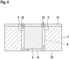
- figure 4 shows a sectional view of a laminated core 2 of a rotor according to a second embodiment of the invention.
- the rotor corresponds to the in figure 1 shown rotor 1, but in contrast to this has no end plates and clamping elements.
- one of the magnet pockets 5 of the rotor is shown, with a magnet stack 6 arranged in it.
- a first free space 8 and a second free space 9 are arranged in the magnet pocket 5, which are each bounded by the magnet stack 6 and the laminated core 2.
- the first space 8 is formed on a side face of the magnet pocket 5 and the second space 9 is formed on an opposite side face of the magnet pocket 5 .
- a casting plate 21 placed on the laminated core 2 is also shown.
- the first free space 8 is uncovered by a filling opening 22 which axially penetrates the casting plate 21 .
- the second free space 9 is uncovered by a ventilation opening 23 which also penetrates the casting plate 21 axially.
- the filling opening 22 and the ventilation opening 23 are each widened at their outer end.
- Each of the flares is frusto-conical in shape, with a diameter increasing toward the outer end of the respective opening.
- first free space 8 and the second free space 9 are connected to one another by a connecting channel 15 to form a continuous channel.
- the channel runs from the filling opening 22 to the ventilation opening 23.
- the connecting channel 15 runs between the magnet stack 6 and an end plate of the laminated core 2.
- the connecting channel 15 can be realized by means of a suitable curvature of the end plate 20.
- the following steps are carried out: In a first method step, the laminated core 2, in which the magnet pockets 5 are arranged, is assembled from stacked electrical laminations.
- each magnet pocket 5 In a second step, several magnets are inserted into each magnet pocket 5 .
- the magnets are lined up axially so that they form a magnet stack 6 .
- two free spaces 8, 9 remain, each of which is delimited by the magnet stack 6 and the laminated core 2.
- the rotor completed in this way is oriented vertically, with one axial side up.
- the casting plate is placed on the laminated core 2 so that the first free space 8 is uncovered through the filling opening 22 and the second free space 9 is uncovered through the ventilation opening 23 .
- a fourth method step the magnets are cast with a casting compound, so that the free spaces 8, 9 are filled with the casting compound.
- the procedure is the same as for the rotor 1 according to the first embodiment of the invention.
- the casting plate is removed from the laminated core 2 .
- the casting compound is cured.
- the rotor shaft 4 through an axially extending central passage opening of the Laminated core 2 are performed so that the laminated core 2 encloses the rotor shaft 4 or is attached to it.
- FIG 5 shows a vehicle 24 with an electric machine 25, which is used to drive the vehicle 24.
- the machine 25 has a housing 26 in which the rotor 1 according to the invention and a stator 27 which surrounds the rotor 1 are accommodated.
Landscapes
- Engineering & Computer Science (AREA)
- Power Engineering (AREA)
- Manufacturing & Machinery (AREA)
- Permanent Field Magnets Of Synchronous Machinery (AREA)
- Manufacture Of Motors, Generators (AREA)
Applications Claiming Priority (1)
| Application Number | Priority Date | Filing Date | Title |
|---|---|---|---|
| DE102021208024.3A DE102021208024A1 (de) | 2021-07-26 | 2021-07-26 | Rotor für eine elektrische Maschine mit einer aufgeweiteten Einfüll- oder Entlüftungsöffnung |
Publications (1)
| Publication Number | Publication Date |
|---|---|
| EP4131732A1 true EP4131732A1 (fr) | 2023-02-08 |
Family
ID=82703161
Family Applications (1)
| Application Number | Title | Priority Date | Filing Date |
|---|---|---|---|
| EP22186749.2A Withdrawn EP4131732A1 (fr) | 2021-07-26 | 2022-07-25 | Rotor pour une machine électrique doté d'un orifice élargi de remplissage ou d'aération |
Country Status (6)
| Country | Link |
|---|---|
| US (1) | US20230026066A1 (fr) |
| EP (1) | EP4131732A1 (fr) |
| JP (1) | JP2023017748A (fr) |
| KR (1) | KR20230016605A (fr) |
| CN (1) | CN115694017A (fr) |
| DE (1) | DE102021208024A1 (fr) |
Citations (2)
| Publication number | Priority date | Publication date | Assignee | Title |
|---|---|---|---|---|
| DE102018009844A1 (de) * | 2018-12-14 | 2019-06-27 | Daimler Ag | Verfahren zum Herstellen einer Blechpaketeinheit für eine elektrische Maschine, insbesondere eines Kraftfahrzeugs |
| WO2020196768A1 (fr) * | 2019-03-28 | 2020-10-01 | アイシン精機株式会社 | Procédé de fabrication d'un noyau de moteur |
Family Cites Families (1)
| Publication number | Priority date | Publication date | Assignee | Title |
|---|---|---|---|---|
| DE102008027758B4 (de) | 2008-06-11 | 2010-09-09 | Siemens Aktiengesellschaft | Rotor für eine permanentmagneterregte dynamoelektrische Maschine |
-
2021
- 2021-07-26 DE DE102021208024.3A patent/DE102021208024A1/de active Pending
-
2022
- 2022-07-19 CN CN202210849691.7A patent/CN115694017A/zh active Pending
- 2022-07-22 KR KR1020220090707A patent/KR20230016605A/ko unknown
- 2022-07-25 EP EP22186749.2A patent/EP4131732A1/fr not_active Withdrawn
- 2022-07-25 JP JP2022118220A patent/JP2023017748A/ja active Pending
- 2022-07-26 US US17/814,974 patent/US20230026066A1/en active Pending
Patent Citations (2)
| Publication number | Priority date | Publication date | Assignee | Title |
|---|---|---|---|---|
| DE102018009844A1 (de) * | 2018-12-14 | 2019-06-27 | Daimler Ag | Verfahren zum Herstellen einer Blechpaketeinheit für eine elektrische Maschine, insbesondere eines Kraftfahrzeugs |
| WO2020196768A1 (fr) * | 2019-03-28 | 2020-10-01 | アイシン精機株式会社 | Procédé de fabrication d'un noyau de moteur |
Also Published As
| Publication number | Publication date |
|---|---|
| DE102021208024A1 (de) | 2023-01-26 |
| US20230026066A1 (en) | 2023-01-26 |
| CN115694017A (zh) | 2023-02-03 |
| KR20230016605A (ko) | 2023-02-02 |
| JP2023017748A (ja) | 2023-02-07 |
Similar Documents
| Publication | Publication Date | Title |
|---|---|---|
| EP3669439B1 (fr) | Rotor pour moteur électrique, en particulier d'un véhicule automobile, et procédé de fabrication dudit rotor | |
| DE60117084T2 (de) | Rotierende elektrische Maschine und ihr Herstellungsverfahren | |
| DE102008027758B4 (de) | Rotor für eine permanentmagneterregte dynamoelektrische Maschine | |
| DE112004001898T5 (de) | Kurzschlußteil, Kommutator und Verfahren zur Herstellung eines Kurzschlußteils | |
| DE102019118608A1 (de) | Elektrische maschine mit schlitzschliessern | |
| WO2023274632A1 (fr) | Rotor pourvu d'une plaque d'extrémité présentant une ouverture de remplissage | |
| EP4131732A1 (fr) | Rotor pour une machine électrique doté d'un orifice élargi de remplissage ou d'aération | |
| EP4191838A1 (fr) | Rotor pour une machine électrique avec un canal de refroidissement radial dans le paquet de tôles | |
| EP3648309B1 (fr) | Moteur à commutation électronique pour un outil portatif électrique ainsi que procédé de fabrication d'un rotor pour un moteur à commutation électronique | |
| DE102021206836A1 (de) | Rotor mit einer Einfüllöffnung mit einer Führung | |
| DE102021206834A1 (de) | Rotor mit einer Endplatte mit einem Verbindungskanal | |
| WO2023274634A1 (fr) | Rotor pourvu d'une plaque d'extrémité présentant une ouverture d'aération radiale | |
| DE102021210913A1 (de) | Rotor für eine elektrische Maschine mit einem Verbindungskanal | |
| WO2023274631A1 (fr) | Rotor pourvu d'une tôle d'extrémité présentant un bombement | |
| WO2023274633A1 (fr) | Rotor pourvu d'une plaque d'extrémité présentant un évidement | |
| WO2023110914A1 (fr) | Rotor pour une machine électrique ayant un canal de refroidissement tubulaire | |
| WO2023110769A1 (fr) | Rotor pour une machine électrique comprenant un canal de refroidissement dans un séparateur de pôles | |
| EP1995852A2 (fr) | Entraînement d'ascenseur et son procédé de fabrication | |
| DE102021204268A1 (de) | Bauteil für eine elektrische Maschine mit einem zylinderförmigen Blechpaketstapel | |
| WO2022058237A1 (fr) | Rotor pour une machine électrique, procédé de production d'un rotor pour une machine électrique et machine électrique pour un véhicule | |
| DE102021213807A1 (de) | Rotor für eine elektrische Maschine mit einem axialen Kühlkanal in einem Blechpaket | |
| DE102022200727A1 (de) | Verfahren zum Imprägnieren eines Rotors für eine elektrische Maschine | |
| DE102022129702A1 (de) | Vergusskörper und Verfahren zum Einbringen von Vergussmasse in einen Rotor einer elektrischen Maschine | |
| EP4191832A1 (fr) | Rotor pour une machine électrique avec un canal de refroidissement s'étendant axialement | |
| DE102022105593A1 (de) | Verfahren zur Herstellung einer magnetisch wirkenden Komponente einer elektrischen Rotationsmaschine, Positionierungssystem und elektrische Rotationsmaschine |
Legal Events
| Date | Code | Title | Description |
|---|---|---|---|
| PUAI | Public reference made under article 153(3) epc to a published international application that has entered the european phase |
Free format text: ORIGINAL CODE: 0009012 |
|
| STAA | Information on the status of an ep patent application or granted ep patent |
Free format text: STATUS: THE APPLICATION HAS BEEN PUBLISHED |
|
| AK | Designated contracting states |
Kind code of ref document: A1 Designated state(s): AL AT BE BG CH CY CZ DE DK EE ES FI FR GB GR HR HU IE IS IT LI LT LU LV MC MK MT NL NO PL PT RO RS SE SI SK SM TR |
|
| STAA | Information on the status of an ep patent application or granted ep patent |
Free format text: STATUS: THE APPLICATION IS DEEMED TO BE WITHDRAWN |
|
| 18D | Application deemed to be withdrawn |
Effective date: 20230809 |