EP4131718A2 - Procédé et système de fonctionnement de modules d'alimentation sans coupure connectés en parallèle - Google Patents
Procédé et système de fonctionnement de modules d'alimentation sans coupure connectés en parallèle Download PDFInfo
- Publication number
- EP4131718A2 EP4131718A2 EP22156226.7A EP22156226A EP4131718A2 EP 4131718 A2 EP4131718 A2 EP 4131718A2 EP 22156226 A EP22156226 A EP 22156226A EP 4131718 A2 EP4131718 A2 EP 4131718A2
- Authority
- EP
- European Patent Office
- Prior art keywords
- ups
- efficiency level
- ups modules
- modules
- bypass
- Prior art date
- Legal status (The legal status is an assumption and is not a legal conclusion. Google has not performed a legal analysis and makes no representation as to the accuracy of the status listed.)
- Pending
Links
Images


Classifications
-
- H—ELECTRICITY
- H02—GENERATION; CONVERSION OR DISTRIBUTION OF ELECTRIC POWER
- H02J—ELECTRIC POWER NETWORKS; CIRCUIT ARRANGEMENTS OR SYSTEMS FOR SUPPLYING OR DISTRIBUTING ELECTRIC POWER; SYSTEMS FOR STORING ELECTRIC ENERGY
- H02J9/00—Circuit arrangements for emergency or stand-by power supply, e.g. for emergency lighting
- H02J9/04—Circuit arrangements for emergency or stand-by power supply, e.g. for emergency lighting in which the distribution system is disconnected from the normal source and connected to a standby source
- H02J9/06—Circuit arrangements for emergency or stand-by power supply, e.g. for emergency lighting in which the distribution system is disconnected from the normal source and connected to a standby source with automatic change-over, e.g. UPS systems
- H02J9/068—Electronic means for switching from one power supply to another power supply, e.g. to avoid parallel connection
-
- H—ELECTRICITY
- H02—GENERATION; CONVERSION OR DISTRIBUTION OF ELECTRIC POWER
- H02J—ELECTRIC POWER NETWORKS; CIRCUIT ARRANGEMENTS OR SYSTEMS FOR SUPPLYING OR DISTRIBUTING ELECTRIC POWER; SYSTEMS FOR STORING ELECTRIC ENERGY
- H02J9/00—Circuit arrangements for emergency or stand-by power supply, e.g. for emergency lighting
- H02J9/005—Circuit arrangements for emergency or stand-by power supply, e.g. for emergency lighting using a power saving mode
- H02J9/007—Detection of the absence of a load
-
- H—ELECTRICITY
- H02—GENERATION; CONVERSION OR DISTRIBUTION OF ELECTRIC POWER
- H02J—ELECTRIC POWER NETWORKS; CIRCUIT ARRANGEMENTS OR SYSTEMS FOR SUPPLYING OR DISTRIBUTING ELECTRIC POWER; SYSTEMS FOR STORING ELECTRIC ENERGY
- H02J9/00—Circuit arrangements for emergency or stand-by power supply, e.g. for emergency lighting
- H02J9/04—Circuit arrangements for emergency or stand-by power supply, e.g. for emergency lighting in which the distribution system is disconnected from the normal source and connected to a standby source
- H02J9/06—Circuit arrangements for emergency or stand-by power supply, e.g. for emergency lighting in which the distribution system is disconnected from the normal source and connected to a standby source with automatic change-over, e.g. UPS systems
-
- Y—GENERAL TAGGING OF NEW TECHNOLOGICAL DEVELOPMENTS; GENERAL TAGGING OF CROSS-SECTIONAL TECHNOLOGIES SPANNING OVER SEVERAL SECTIONS OF THE IPC; TECHNICAL SUBJECTS COVERED BY FORMER USPC CROSS-REFERENCE ART COLLECTIONS [XRACs] AND DIGESTS
- Y02—TECHNOLOGIES OR APPLICATIONS FOR MITIGATION OR ADAPTATION AGAINST CLIMATE CHANGE
- Y02E—REDUCTION OF GREENHOUSE GAS [GHG] EMISSIONS, RELATED TO ENERGY GENERATION, TRANSMISSION OR DISTRIBUTION
- Y02E40/00—Technologies for an efficient electrical power generation, transmission or distribution
- Y02E40/30—Reactive power compensation
-
- Y—GENERAL TAGGING OF NEW TECHNOLOGICAL DEVELOPMENTS; GENERAL TAGGING OF CROSS-SECTIONAL TECHNOLOGIES SPANNING OVER SEVERAL SECTIONS OF THE IPC; TECHNICAL SUBJECTS COVERED BY FORMER USPC CROSS-REFERENCE ART COLLECTIONS [XRACs] AND DIGESTS
- Y02—TECHNOLOGIES OR APPLICATIONS FOR MITIGATION OR ADAPTATION AGAINST CLIMATE CHANGE
- Y02E—REDUCTION OF GREENHOUSE GAS [GHG] EMISSIONS, RELATED TO ENERGY GENERATION, TRANSMISSION OR DISTRIBUTION
- Y02E40/00—Technologies for an efficient electrical power generation, transmission or distribution
- Y02E40/40—Arrangements for reducing harmonics
Definitions
- the present disclosure generally relates to the field of UPS, and in particular to a method and a system for operation of UPS modules connected in parallel.
- a UPS system may include one or multiple racks. Each rack may include multiple UPS modules.
- Each rack may include multiple UPS modules.
- operation modes in the conventional technology have defects. For example, in an ECO energy-saving mode, although the operation efficiency of the UPS system is improved, the power factor of the bypass current cannot be guaranteed, and the power grid may be polluted due to an addition of a load.
- a smart parallel sleep mode although the operation efficiency of the system is improved, the reliability is reduced.
- a method and a system for operation of UPS modules connected in parallel are provided to solve the technical problems in the conventional technology, improve the operation efficiency of the system and achieve high reliability.
- the method includes:
- the step S1 further includes:
- step S13 further includes:
- the first predetermined number of UPS modules include one UPS module or all UPS modules included in a tower crane rack.
- an efficiency level of the UPS system in a case that a system load percentage is less than 20%, an efficiency level of the UPS system is an eighth efficiency level; in a case that a system load percentage is greater than or equal to 20% and less than 30%, an efficiency level of the UPS system is a seventh efficiency level; in a case that a system load percentage is greater than or equal to 30% and less than 40%, an efficiency level of the UPS system is a fourth efficiency level; in a case that a system load percentage is greater than or equal to 40% and less than 50%, an efficiency level of the UPS system is a first efficiency level; in a case that a system load percentage is greater than or equal to 50% and less than 60%, an efficiency level of the UPS system is a second efficiency level; in a case that a system load percentage is greater than or equal to 60% and less than 70%, an efficiency level of the UPS system is a third efficiency level; in a case that a system load percentage is greater than or equal to 70% and less than 80%, an efficiency level of the UPS system is a seventh efficiency level; in
- the step S14 further includes: step S14a, controlling UPS modules not being slept in the multiple UPS modules to enter into the main-bypass common mode and simultaneously performing bypass current sharing and harmonic compensation.
- step S14 further includes:
- the step S15 further includes: controlling, for each of the UPS modules not being slept, the UPS module to operate in the dynamic online mode or return to the main-inverter power supply mode in a case that the bypass current of the UPS module leads the bypass voltage by a predetermined angle and an input power factor is greater than a predetermined value.
- step S2 further includes:
- the system includes multiple UPS modules and a processor.
- the processor stores a computer program.
- the computer program when executed by the processor, causes the processor to perform the method for operation of UPS modules connected in parallel.
- the system includes multiple UPS modules.
- the system further includes a sleeping module and a waking module.
- the sleeping module is configured to, in a case that a UPS system is constructed based on multiple UPS modules connected in parallel, sleep a predetermined number of UPS modules in the multiple UPS modules based on a system load rate to control the UPS system to operate at a predetermined efficiency level, and control UPS modules not being slept in the multiple UPS modules of the UPS system to enter into a main-inverter power supply mode or a main-bypass common mode to perform reactive power and harmonic compensation.
- the waking module is configured to wake up the slept UPS modules when the system load rate drops by a predetermined value due to a sudden addition of a load.
- the sleeping module further includes a first mode control unit, a sleeping unit, a second mode control unit, and a third mode control unit.
- the first mode control unit is configured to construct the UPS system with the multiple UPS modules connected in parallel, and control the UPS modules to operate in the main-inverter power supply mode.
- the sleeping unit is configured to determine whether it is required to sleep the UPS modules based on the system load rate; sleep a predetermined number of UPS modules to control the UPS system to operate at a first efficiency level or a second efficiency level in a case that it is required to sleep the UPS modules based on the system load rate; and control the UPS modules to operate in the main-inverter power supply mode in a case that it is not required to sleep the UPS modules based on the system load rate.
- the second mode control unit is configured to control UPS modules not being slept in the multiple UPS modules to enter into the main-bypass common mode to perform reactive power and harmonic compensation.
- the third mode control unit is configured to control, for each of the UPS modules not being slept, the UPS module to operate in a dynamic online mode or return to the main-inverter power supply mode based on a relationship between a bypass current and a bypass voltage.
- the sleeping unit is further configured to: sleep a first predetermined number of UPS modules in a predetermined order and obtain a current efficiency level; calculate an estimated efficiency level after sleeping a second predetermined number of UPS modules in the predetermined order; determine whether the current efficiency level is greater than the estimated efficiency level; repeat the preceding three steps in a case that the current efficiency level is greater than the estimated efficiency level; and control the UPS system to operate at a current operation state in a case that the current efficiency level is not greater than the estimated efficiency level.
- the first predetermined number of UPS modules include one UPS module or all UPS modules included in a tower crane rack.
- an efficiency level of the UPS system in a case that a system load percentage is less than 20%, an efficiency level of the UPS system is an eighth efficiency level; in a case that a system load percentage is greater than or equal to 20% and less than 30%, an efficiency level of the UPS system is a seventh efficiency level; in a case that a system load percentage is greater than or equal to 30% and less than 40%, an efficiency level of the UPS system is a fourth efficiency level; in a case that a system load percentage is greater than or equal to 40% and less than 50%, an efficiency level of the UPS system is a first efficiency level; in a case that a system load percentage is greater than or equal to 50% and less than 60%, an efficiency level of the UPS system is a second efficiency level; in a case that a system load percentage is greater than or equal to 60% and less than 70%, an efficiency level of the UPS system is a third efficiency level; in a case that a system load percentage is greater than or equal to 70% and less than 80%, an efficiency level of the UPS system is a seventh efficiency level; in
- the second mode control unit further includes a first compensation sub-unit configured to control UPS modules not being slept in the multiple UPS modules to enter into the main-bypass common mode and simultaneously perform bypass current sharing and harmonic compensation.
- the second mode control unit further includes a second compensation sub-unit and a current sharing sub-unit.
- the second compensation sub-unit is configured to control UPS modules not being slept to enter into the main-bypass common mode, control a main power unit of the UPS modules to invert to perform reactive power and harmonic compensation, control a bypass current to be sinusoidal, and control the bypass current to lead the bypass voltage for a first predetermined time period.
- the current sharing sub-unit is configured to adjust a bypass power tube drive of the UPS module based on a bypass power balance to share the bypass current of the UPS module for a second predetermined time period.
- the third mode control unit is further configured to control, for each of the UPS modules not being slept, the UPS module to operate in the dynamic online mode or return to the main-inverter power supply mode in a case that the bypass current of the UPS module leads the bypass voltage by a predetermined angle and an input power factor is greater than a predetermined value.
- the waking module further includes a first waking unit or a second waking unit.
- the first waking unit is configured to wake up the slept UPS modules when the system load rate drops by at least two efficiency levels due to the sudden addition of the load, control all the UPS modules to enter into the main-inverter power supply mode, and trigger the sleeping module to operate cyclically.
- the second waking unit is configured to wake up the slept UPS modules when the system load rate drops by at least two efficiency levels due to the sudden addition of the load and control the waked UPS modules to directly enter into the dynamic online mode.
- the UPS modules can be slept or waked up intelligently based on the system load rate, improving the operation efficiency of the system, achieving high reliability, and thereby ensuring that the UPS system operates around highest efficiency.
- reactive power and harmonic compensation can be performed on the bypass current to improve the input power factor and reduce the harmonic pollution to the power grid, and the UPS system can quickly switch from the main-bypass common mode to the main-inverter power supply mode when the input voltage is abnormal or a short circuit occurs, ensuring that the output voltage meets a class 1 curve.
- the transient state of the UPS module switching from the main-inverter power supply mode to the main-bypass common mode is performed in two stages, reducing the influence of mutual coupling between bypass current sharing and dynamic online compensation, and improving the power factor of the bypass input circuit.
- a method for operation of UPS modules connected in parallel includes: in a case that a UPS system is constructed based on multiple UPS modules connected in parallel, sleeping a predetermined number of UPS modules in the multiple UPS modules based on a system load rate to control the UPS system to operate at a predetermined efficiency level; controlling UPS modules not being slept in the multiple UPS modules of the UPS system to enter into a main-inverter power supply mode or a main-bypass common mode to perform reactive power and harmonic compensation; and waking up the slept UPS modules when the system load rate drops by a predetermined value due to a sudden addition of a load.
- the UPS modules can be slept or waked up intelligently based on the system load rate, improving the operation efficiency of the system, achieving high reliability, and thereby ensuring that the UPS system operates around highest efficiency.
- FIG. 1 is a flow chart of a method for operation of UPS modules connected in parallel according to a first preferred embodiment of the present disclosure.
- step S1 in a case that a UPS system is constructed based on multiple UPS modules connected in parallel, a predetermined number of UPS modules in the multiple UPS modules are slept based on a system load rate to control the UPS system to operate at a predetermined efficiency level, and UPS modules not being slept in the multiple UPS modules of the UPS system are controlled to enter into a main-inverter power supply mode or a main-bypass common mode to perform reactive power and harmonic compensation.
- a main-inverter power supply mode is entered into so as to supply power to a load.
- a predetermined number of the UPS modules may be slept based on a system load rate to control the UPS system to operate at a predetermined efficiency level.
- the UPS system may include multiple racks connected in parallel, each of the racks includes multiple UPS modules, and all the UPS modules in each of the racks are slept simultaneously.
- the UPS system may include multiple UPS modules connected in parallel, and each of the UPS modules is slept independently.
- the load may be divided into multiple levels, for example, nine levels.
- a predetermined efficiency level such as a first efficiency level or a second efficiency level
- a predetermined number of the UPS modules may be slept.
- UPS modules included in a rack or UPS modules included in several racks are slept, or a UPS module or several UPS modules are slept. In this way, the UPS system can be controlled to operate at highest system efficiency.
- the UPS modules not being slept in the UPS system are controlled to enter into a main-inverter power supply mode or a main-bypass common mode (that is, a VI mode), the bypass circuit outputs an active power, reactive power and harmonic compensation are performed, and batteries in the UPS modules are charged, so that the power factor of the bypass input current is close to 1.
- step S2 when the system load rate drops by a predetermined value due to a sudden addition of a load, the slept UPS modules are waked up.
- the slept UPS modules are waked up within a short period of time, such as 3ms, and quickly enter into the inverter power supply, ensuring high reliability of power supply. Even if the input voltage is abnormal or a short circuit occurs, the slept UPS modules quickly switch from a current mode to the main-inverter power supply mode.
- the slept UPS modules are waked up and controlled to enter into a dynamic online mode.
- the dynamic online mode is a mode in which the output voltage of the UPS system meets a type of curve, such as a line standard curve (Class 1).
- the UPS system may be not stable. Therefore, in a further preferred embodiment of the present disclosure, when the system load rate drops by at least two efficiency levels due to the sudden addition of the load, the slept UPS modules are waked up, all the UPS modules are controlled to enter into the main-inverter power supply mode, and step S1 is performed cyclically. In this way, each of the UPS modules switches from a current operation mode to the main-inverter power supply mode, and step S1 is performed cyclically, further improving the reliability of the UPS system.
- the UPS modules can be slept or waked up intelligently based on the system load rate, improving the operation efficiency of the system, achieving high reliability, and thereby ensuring that the UPS system operates around highest efficiency.
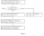
- FIG. 2 is a flow chart of a method for operation of UPS modules connected in parallel according to a second preferred embodiment of the present disclosure.
- Figure 3 is a schematic diagram showing a principle of the method for operation of UPS modules connected in parallel shown in Figure 2 .
- the UPS system is constructed with the multiple UPS modules connected in parallel, and the UPS modules are controlled to operate in the main-inverter power supply mode.
- a main-inverter power supply mode is entered into so as to supply power to a load.
- a predetermined number of the UPS modules may be slept based on a system load rate to control the UPS system to operate at a predetermined efficiency level.
- the UPS system may include multiple racks connected in parallel, each of the racks includes multiple UPS modules, and all the UPS modules in each of the racks are slept simultaneously.
- the UPS system may include multiple UPS modules connected in parallel, and each of the UPS modules is slept independently.
- step S2 it is determined whether it is required to sleep the UPS modules based on the system load rate. In a case that it is required to sleep the UPS modules based on the system load rate, proceed to step S3. In a case that it is not required to sleep the UPS modules based on the system load rate, proceed to step S6 to control the UPS modules to operate in the main-inverter power supply mode.
- the load may be divided into multiple levels, for example, nine levels.
- an efficiency level of the UPS system is an eighth efficiency level; in a case that a system load percentage is greater than or equal to 20% and less than 30%, an efficiency level of the UPS system is a seventh efficiency level; in a case that a system load percentage is greater than or equal to 30% and less than 40%, an efficiency level of the UPS system is a fourth efficiency level; in a case that a system load percentage is greater than or equal to 40% and less than 50%, an efficiency level of the UPS system is a first efficiency level; in a case that a system load percentage is greater than or equal to 50% and less than 60%, an efficiency level of the UPS system is a second efficiency level; in a case that a system load percentage is greater than or equal to 60% and less than 70%, an efficiency level of the UPS system is a third efficiency level; in a case that
- a lower efficiency level indicates that an efficiency of the UPS system is a higher efficiency.
- it is required to control the UPS system to operate at a lower efficiency level. Therefore, for example, in a case it is determined based on the system load rate that the efficiency level of the UPS system is higher than the second efficiency level, that is, the third efficiency level or a higher efficiency level, the UPS modules are slept.
- step S3 a predetermined number of UPS modules are slept to control the UPS system to operate at the first efficiency level or the second efficiency level.
- the UPS system in a case that the UPS system includes multiple racks connected in parallel, and each of the racks includes multiple UPS modules, all the UPS modules in each of the racks may be slept simultaneously, or one of the UPS modules may be slept. In another preferred embodiment of the present disclosure, in a case that the UPS system includes multiple UPS modules connected in parallel, one of the UPS modules may be slept independently at a time.
- a first predetermined number of UPS modules are slept in a predetermined order and a current efficiency level is obtained.
- an estimated efficiency level after sleeping a second predetermined number of UPS modules in the predetermined order is calculated.
- the first predetermined number of UPS modules and the second predetermined number of UPS modules may be one UPS module, or may be all the UPS modules included in a rack.
- the predetermined order it indicates that the UPS modules are numbered first, and then the UPS modules are polled in a descending order or an ascending order of the numbers of the UPS modules.
- UPS modules may be numbered as shown in the following table: Number Rack 1 Rack 2 Rack 3 Rack 4 Rack 5 UPS module 1 1 6 11 16 21 UPS module 2 2 6 12 17 22 UPS module 3 3 8 13 18 23 UPS module 4 4 8 14 19 24 UPS module 5 5 10 15 20 25
- the UPS module 1 is slept according to an ascending order of the numbers 1 to 25, and then a current efficiency level is calculated. Every time a UPS module is slept, the system load rate changes, and the current efficiency level corresponding to the system load rate changes. Then, an estimated efficiency level after UPS module 2 is slept is calculated. It is determined whether the current efficiency level is greater than the estimated efficiency level, that is, it is determined whether the efficiency level is decreased by sleeping the UPS modules.
- UPS module 2 In a case that the efficiency level is decreased by sleeping the UPS modules, UPS module 2 is slept, then an estimated efficiency level after UPS module 3 is slept is calculated, and then the current efficiency level is compared with the estimated efficiency level, and so on, until the estimated efficiency level is not to be decreased by sleeping the UPS modules.
- the system is controlled to operate at a highest efficiency, that is, an efficiency level of the UPS system is the first efficiency level or the second efficiency level.
- all the UPS modules in each of the racks may be slept at a time.
- the principle and method are the same as the above embodiments, and are not repeated herein.
- step S4 UPS modules not being slept in the multiple of UPS modules are controlled to enter into the main-bypass common mode to perform reactive power and harmonic compensation.
- the UPS modules not being slept in the multiple UPS modules are controlled to enter into the main-bypass common mode (that is, a VI mode), and reactive power and harmonic compensation are performed simultaneously.
- the transient state of the UPS modules not being slept switching from the main-inverter mode (VFI mode) to the main-bypass common mode (VI mode) is adjusted in two stages.
- the UPS modules not being slept are controlled to enter into the main-bypass common mode (VI mode)
- a main power unit of each of the UPS modules not being slept is controlled to invert to perform reactive power and harmonic compensation
- a bypass current is controlled to be sinusoidal
- the bypass current is controlled to lead the bypass voltage for a first predetermined time period.
- the UPS modules that are not sleeping are controlled to enter into the main-bypass common mode, and reactive and harmonic compensation are performed in a first predetermined time (such as, 40S), so that the bypass current is sinusoidal, and the phase of the bypass current is substantially the same as the phase of the bypass voltage.
- the phase of the bypass current is controlled to lead the phase of the bypass voltage by 5 to 10 degrees, that is, a capacitive load is added, so that the bypass current leads the voltage.
- zero-crossing shutdown is performed on a bypass SCR in advance, without affecting the output voltage of the UPS system.
- the output voltage meets the class 1 curve, that is, the dynamic online mode is entered.
- Making the zero-crossing shutdown of the bypass SCR in advance can also prepare for the subsequent adjustment of bypass current sharing. It is known by those skilled in the art that the first predetermined time period and the leading angle may be adjusted according to actual requirements.
- a bypass power tube drive of the UPS module is adjusted based on a bypass power balance to share the bypass current of the UPS module for a second predetermined time period. For example, in the second predetermined period (such as, 20s) after phase 1, for each of the UPS modules in each of the racks, the bypass power tube drive of the UPS module is adjusted based on the bypass power balance to share the bypass current of the UPS module, sharing the bypass current of each of the racks, achieving stable reactive power and harmonic compensation, thereby making the UPS system stable.
- the transient state of the UPS system switching from the VFI mode to the VI mode is divided into two stages for control, reducing the influence of mutual coupling between bypass current sharing and dynamic online compensation in connecting racks in parallel, and improving the power factor of the bypass input current.
- step S5 for each of the UPS modules not being slept, the UPS module is controlled to operate in the dynamic online mode or return to the main-inverter power supply mode based on a relationship between a bypass current and a bypass voltage.
- the UPS module for each of the UPS modules not being slept, the UPS module is controlled to operate in the dynamic online mode or return to the main-inverter power supply mode in a case that the bypass current of the UPS module leads the bypass voltage by a predetermined angle and an input power factor is greater than a predetermined value. For example, for each of the racks or for each of the UPS modules, the relationship between the bypass current and the bypass voltage is determined, and it is determined whether the dynamic online mode is exited.
- the UPS module In a case of meeting a condition, the UPS module is controlled to operate in the dynamic online mode and run efficiently. In a case of not meeting a condition, the UPS module is controlled to switch from the dynamic online mode to the main-inverter power supply mode, and it is determined whether to enter into the dynamic online mode after the condition is met.
- the dynamic online mode is maintained in a condition that the bypass current leads the bypass voltage by more than about 5 degrees and the input power is greater than 0.975, and the dynamic online mode is exited in other conditions.
- the dynamic online mode is a mode in which the output voltage meets the class 1 curve.
- the slept UPS modules are waked up when the system load rate drops by a predetermined value due to a sudden addition of the load.
- the slept UPS modules are waked up when the load is suddenly increased, for example, when the system load rate drops by at least two efficiency levels due to the sudden addition of the load, and the waked UPS modules are controlled to directly enter into the dynamic online mode.
- the dynamic online mode is a mode in which the output voltage of the UPS system meets a type of curve, such as a line standard curve (Class 1).
- the UPS system may be not stable. Therefore, in a further preferred embodiment of the present disclosure, when the system load rate drops by at least two efficiency levels (for example, the efficiency level changes from 1 to 3) due to the sudden addition of the load, the slept UPS modules are waked up, all the UPS modules are controlled to enter into the main-inverter power supply mode, and steps S1 to S5 are performed cyclically. In this way, each of the UPS modules switches from a current operation mode to the main-inverter power supply mode, and steps S1 to S5 are performed cyclically, further improving the reliability of the UPS system.
- efficiency levels for example, the efficiency level changes from 1 to 3
- the UPS modules can be slept or waked up intelligently based on the system load rate, improving the operation efficiency of the system, achieving high reliability, and thereby ensuring that the UPS system operates around highest efficiency.
- reactive power and harmonic compensation can be performed on the bypass current to improve the input power factor and reduce the harmonic pollution to the power grid.
- the transient state of the UPS module switching from the main-inverter power supply mode to the main-bypass common mode is performed in two stages, reducing the influence of mutual coupling between bypass current sharing and dynamic online compensation, and improving the power factor of the bypass input circuit.
- a system for operation of UPS modules connected in parallel includes multiple UPS modules and a processor.
- the processor stores a computer program.
- the computer program contains all the features for implementing the method according to the present disclosure.
- the computer program when installed in the processor, causes the processor to perform the method according to the present disclosure.
- the computer program in the present disclosure is any expression, in any language, code or notation, of a set of instructions intended to cause a system having an information processing capability to perform a particular function either directly or after either or both of the following steps: a) converting to other languages, codes or symbols; b) reproducing in different formats.
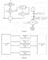
- FIG 4 is a schematic block diagram of a system for operation of UPS modules connected in parallel according to a first preferred embodiment of the present disclosure.
- the system for operation of UPS modules connected in parallel according to the present disclosure includes multiple UPS modules 310, 320, 330, ..., and 3N0, a sleeping module 100, and a waking module 200.
- the multiple UPS modules 310, 320, 330, ..., and 3N0 may be UPS modules in multiple racks connected in parallel, or may be different UPS modules. Therefore, as mentioned above, the UPS system may include multiple racks connected in parallel, each of the racks includes multiple UPS modules, and all the UPS modules in each of the racks are slept simultaneously. In another preferred embodiment of the present disclosure, the UPS system may include multiple UPS modules connected in parallel, and each of the UPS modules is slept independently.
- the sleeping module 100 is configured to, in a case that a UPS system is constructed based on multiple UPS modules connected in parallel, sleep a predetermined number of UPS modules in the multiple UPS modules based on a system load rate to control the UPS system to operate at a predetermined efficiency level, and control the UPS modules not being slept in the multiple UPS modules of the UPS system to enter into a main-inverter power supply mode or a main-bypass common mode to perform reactive power and harmonic compensation.
- the waking module 200 is configured to wake up the slept UPS modules when the system load rate drops by a predetermined value due to a sudden addition of a load.
- the sleeping module 100 and the waking module 200 may be implemented with reference to the embodiment shown in Figure 1 , which is not repeated herein.
- FIG. 5 is a schematic block diagram of a system for operation of UPS modules connected in parallel according to a second preferred embodiment of the present disclosure.
- the system for operation of UPS modules connected in parallel according to the present disclosure includes multiple UPS modules 310, 320, 330, ..., and 3N0, a sleeping module 100, and a waking module 200.
- the sleeping module 100 further includes a first mode control unit 110, a sleeping unit 120, a second mode control unit 130, and a third mode control unit 140.
- the first mode control unit 110 is configured to construct the UPS system with the multiple UPS modules 310, 320, 330, ..., and 3N0 connected in parallel, and control the UPS modules 310, 320, 330, ... , and 3N0 to operate in the main-inverter power supply mode.
- the sleeping unit 120 is configured to determine whether it is required to sleep the UPS modules 310, 320, 330, ..., and 3N0 based on the system load rate, sleep a predetermined number of UPS modules to control the UPS system to operate at a first efficiency level or a second efficiency level in a case that it is required to sleep the UPS modules 310, 320, 330, ..., and 3N0 based on the system load rate, and control the UPS modules to operate in the main-inverter power supply mode in a case that it is not required to sleep the UPS modules 310, 320, 330, ..., and 3N0 based on the system load rate.
- the first predetermined number of UPS modules include one UPS module or all UPS modules included in a tower crane rack.
- an efficiency level of the UPS system is an eighth efficiency level; in a case that a system load percentage is greater than or equal to 20% and less than 30%, an efficiency level of the UPS system is a seventh efficiency level; in a case that a system load percentage is greater than or equal to 30% and less than 40%, an efficiency level of the UPS system is a fourth efficiency level; in a case that a system load percentage is greater than or equal to 40% and less than 50%, an efficiency level of the UPS system is a first efficiency level; in a case that a system load percentage is greater than or equal to 50% and less than 60%, an efficiency level of the UPS system is a second efficiency level; in a case that a system load percentage is greater than or equal to 60% and less than 70%, an efficiency level of the UPS system is a third efficiency level; in a case that a system load percentage is greater than or equal to 70% and less than 80%, an efficiency level of the UPS system is a fifth efficiency level; in a case that a system load percentage
- the sleeping unit 120 is further configured to: sleep a first predetermined number of UPS modules in a predetermined order and obtain a current efficiency level; calculate an estimated efficiency level after sleeping a second predetermined number of UPS modules in the predetermined order; determine whether the current efficiency level is greater than the estimated efficiency level; repeat the above steps in a case that the current efficiency level is greater than the estimated efficiency level; and the current operation state is maintained in a case that the current efficiency level is not greater than the estimated efficiency level.
- the second mode control unit 130 is configured to control UPS modules not being slept in the multiple UPS modules to enter into the main-bypass common mode to perform reactive power and harmonic compensation.
- the second mode control unit 130 may include: a second compensation sub-unit 131 and a current sharing sub-unit 132.
- the second compensation sub-unit 131 is configured to control UPS modules not being slept to enter into the main-bypass common mode, control a main power unit of the UPS modules not being slept to invert to perform reactive power and harmonic compensation, control a bypass current to be sinusoidal, and control the bypass current to lead the bypass voltage for a first predetermined time period.
- the current sharing sub-unit 132 is configured to adjust, for each of the UPS modules not being slept, a bypass power tube drive of the UPS module based on a bypass power balance to share the bypass current of the UPS module for a second predetermined time period.
- the second mode control unit 130 may perform controlling in a different way, that is, perform bypass current sharing and harmonic compensation.
- the second mode control unit 130 may include a first compensation sub-unit configured to control UPS modules not being slept to enter into the main-bypass common mode and simultaneously perform bypass current sharing and harmonic compensation.
- the third mode control unit 140 is configured to control, for each of the UPS modules not being slept, the UPS module to operate in a dynamic online mode or return to the main-inverter power supply mode based on a relationship between a bypass current and a bypass voltage.
- the third mode control unit 140 is further configured to control, for each of the UPS modules not being slept, the UPS module to operate in the dynamic online mode or return to the main-inverter power supply mode in a case that the bypass current of the UPS module leads the bypass voltage by a predetermined angle and an input power factor is greater than a predetermined value.
- the waking module 200 may include a first waking unit 210 or a second waking unit 220 to perform waking processing in different ways.
- the first waking unit 210 is configured to wake up the slept UPS modules when the system load rate drops by at least two efficiency levels due to the sudden addition of the load, control all the UPS modules to enter into the main-inverter power supply mode, and trigger the sleeping module 100 to operate cyclically.
- the second waking unit 220 is configured to wake up the slept UPS modules when the system load rate drops by at least two efficiency levels due to the sudden addition of the load and control the waked UPS modules to directly enter into the dynamic online mode.
- each of the first mode control unit 110, the sleeping unit 120, the second mode control unit 130, the third mode control unit 140, the first compensation sub-unit, the second compensation sub-unit 131, the current sharing sub-unit 132, the first waking unit 210 or the second waking unit 220 can be constructed with reference to the embodiments shown in Figures 2 to 4 and has the same principle as that described in the embodiments shown in Figures 2 to 4 , which are not repeated herein.
- the UPS modules can be slept or waked up intelligently based on the system load rate, improving the operation efficiency of the system, achieving high reliability, and thereby ensuring that the UPS system operates around highest efficiency.
- reactive power and harmonic compensation can be performed on the bypass current to improve the input power factor and reduce the harmonic pollution to the power grid.
- the transient state of the UPS module switching from the main-inverter power supply mode to the main-bypass common mode is performed in two stages, reducing the influence of mutual coupling between bypass current sharing and dynamic online compensation, and improving the power factor of the bypass input circuit. Therefore, the present disclosure may be implemented by hardware, software or a combination thereof.
- the present disclosure may be implemented in a centralized manner in at least one computer system, or in a distributed manner in different parts distributed in several interconnected computer systems. Any computer systems or other devices suitable for performing the method according to the present disclosure are applicable.
- a typical combination of hardware and software can be a general purpose computer system with a computer program that, when being loaded and executed, causes the computer system to perform the method according to the present disclosure.
Landscapes
- Business, Economics & Management (AREA)
- Emergency Management (AREA)
- Engineering & Computer Science (AREA)
- Power Engineering (AREA)
- Supply And Distribution Of Alternating Current (AREA)
- Inverter Devices (AREA)
Applications Claiming Priority (1)
| Application Number | Priority Date | Filing Date | Title |
|---|---|---|---|
| CN202110885198.6A CN115706447A (zh) | 2021-08-03 | 2021-08-03 | 一种ups模块并联运行方法和系统 |
Publications (2)
| Publication Number | Publication Date |
|---|---|
| EP4131718A2 true EP4131718A2 (fr) | 2023-02-08 |
| EP4131718A3 EP4131718A3 (fr) | 2023-02-22 |
Family
ID=80446674
Family Applications (1)
| Application Number | Title | Priority Date | Filing Date |
|---|---|---|---|
| EP22156226.7A Pending EP4131718A3 (fr) | 2021-08-03 | 2022-02-10 | Procédé et système de fonctionnement de modules d'alimentation sans coupure connectés en parallèle |
Country Status (3)
| Country | Link |
|---|---|
| US (1) | US12027914B2 (fr) |
| EP (1) | EP4131718A3 (fr) |
| CN (1) | CN115706447A (fr) |
Families Citing this family (2)
| Publication number | Priority date | Publication date | Assignee | Title |
|---|---|---|---|---|
| CN119760368B (zh) * | 2025-03-10 | 2026-01-27 | 北京东道科技发展有限公司 | 基于ups的市电故障预测系统 |
| CN120165491B (zh) * | 2025-03-24 | 2025-10-10 | 泰鸣电气设备(天津)有限公司 | 一种高电能质量的ups电源 |
Family Cites Families (2)
| Publication number | Priority date | Publication date | Assignee | Title |
|---|---|---|---|---|
| US7638899B2 (en) * | 2006-03-10 | 2009-12-29 | Eaton Corporation | Nested redundant uninterruptible power supply apparatus and methods |
| PL3088989T3 (pl) * | 2015-04-30 | 2018-08-31 | Abb Schweiz Ag | Działanie ups z wysoką wydajnością przetwornika |
-
2021
- 2021-08-03 CN CN202110885198.6A patent/CN115706447A/zh active Pending
-
2022
- 2022-02-04 US US17/665,362 patent/US12027914B2/en active Active
- 2022-02-10 EP EP22156226.7A patent/EP4131718A3/fr active Pending
Non-Patent Citations (1)
| Title |
|---|
| ANONYMOUS: "IEC 62040-3 Edition 2.0 - Uninterruptible power systems (UPS) - Part 3: Method of specifying the performance and test requirements", 31 March 2011 (2011-03-31), XP093381639, Retrieved from the Internet <URL:No URL> * |
Also Published As
| Publication number | Publication date |
|---|---|
| EP4131718A3 (fr) | 2023-02-22 |
| US12027914B2 (en) | 2024-07-02 |
| US20230041719A1 (en) | 2023-02-09 |
| CN115706447A (zh) | 2023-02-17 |
Similar Documents
| Publication | Publication Date | Title |
|---|---|---|
| EP4131718A2 (fr) | Procédé et système de fonctionnement de modules d'alimentation sans coupure connectés en parallèle | |
| EP4002054A1 (fr) | Système photovoltaïque mlpe et procédé de commande de chaîne photovoltaïque dans un système photovoltaïque mlpe | |
| KR20210105882A (ko) | 다기직류시스템 파워회복단계에서 전압 안전성을 보장하는 종합제어방법 및 시스템 | |
| CN101562349A (zh) | 一种模块化ups的节能控制方法及系统 | |
| CN113420259B (zh) | 安全约束机组组合约束削减方法、装置、终端及介质 | |
| KR101901327B1 (ko) | Ess 기능을 갖는 이중변환 방식 ups를 위한 입력 컨버터 제어 방법 | |
| WO2015123071A1 (fr) | Gestion d'alimentation de secours pour systèmes informatiques | |
| CN103809723A (zh) | 机柜与其电源控制方法 | |
| CN111697556A (zh) | 电气设备的运行控制方法及终端设备 | |
| US11870296B2 (en) | Uninterruptible power system and operation method thereof | |
| CN210246391U (zh) | 一种基于双静态开关控制的不间断电源 | |
| US11050294B1 (en) | Power supply shedding for power efficiency optimization | |
| CN102677097A (zh) | 一种电解铝供电稳流容错控制方法 | |
| CN107565572A (zh) | 一种电网运行方式调整方法及装置 | |
| CN114629224A (zh) | Ups系统直流母线电压的中点平衡控制方法及逆变器 | |
| JPWO2014024731A1 (ja) | 連系系統切替装置及び電力制御システム | |
| CN111384843A (zh) | 基于子模块状态监测的mmc维护周期确定方法及系统 | |
| CN205105110U (zh) | 多电源输入的变频器主电路拓扑结构 | |
| CN109787292A (zh) | 一种多模块并机集中控制的光伏逆变器系统和控制方法 | |
| CN119253720B (zh) | 适用于新能源送出的直流输电装置及其控制方法和设备 | |
| TWI665848B (zh) | 電源供應系統及其控制方法 | |
| CN114189153A (zh) | 宇航分布式电源系统级联稳定性控制方法及实现装置 | |
| CN113300397A (zh) | 一种交直流无功交换参考值优化方法及系统 | |
| CN115543059B (zh) | 一种处理器、处理器系统及片上系统 | |
| CN118263906B (zh) | 一种基于全控型开关器件的储耗一体化装置及其控制方法 |
Legal Events
| Date | Code | Title | Description |
|---|---|---|---|
| PUAI | Public reference made under article 153(3) epc to a published international application that has entered the european phase |
Free format text: ORIGINAL CODE: 0009012 |
|
| STAA | Information on the status of an ep patent application or granted ep patent |
Free format text: STATUS: THE APPLICATION HAS BEEN PUBLISHED |
|
| PUAL | Search report despatched |
Free format text: ORIGINAL CODE: 0009013 |
|
| AK | Designated contracting states |
Kind code of ref document: A2 Designated state(s): AL AT BE BG CH CY CZ DE DK EE ES FI FR GB GR HR HU IE IS IT LI LT LU LV MC MK MT NL NO PL PT RO RS SE SI SK SM TR |
|
| AK | Designated contracting states |
Kind code of ref document: A3 Designated state(s): AL AT BE BG CH CY CZ DE DK EE ES FI FR GB GR HR HU IE IS IT LI LT LU LV MC MK MT NL NO PL PT RO RS SE SI SK SM TR |
|
| RIC1 | Information provided on ipc code assigned before grant |
Ipc: H02J 9/06 20060101ALI20230113BHEP Ipc: H02J 9/00 20060101AFI20230113BHEP |
|
| STAA | Information on the status of an ep patent application or granted ep patent |
Free format text: STATUS: REQUEST FOR EXAMINATION WAS MADE |
|
| 17P | Request for examination filed |
Effective date: 20230718 |
|
| RBV | Designated contracting states (corrected) |
Designated state(s): AL AT BE BG CH CY CZ DE DK EE ES FI FR GB GR HR HU IE IS IT LI LT LU LV MC MK MT NL NO PL PT RO RS SE SI SK SM TR |
|
| STAA | Information on the status of an ep patent application or granted ep patent |
Free format text: STATUS: EXAMINATION IS IN PROGRESS |