EP4131670B1 - Elektrische steckverbindung und gegenstecker - Google Patents
Elektrische steckverbindung und gegenstecker Download PDFInfo
- Publication number
- EP4131670B1 EP4131670B1 EP21189826.7A EP21189826A EP4131670B1 EP 4131670 B1 EP4131670 B1 EP 4131670B1 EP 21189826 A EP21189826 A EP 21189826A EP 4131670 B1 EP4131670 B1 EP 4131670B1
- Authority
- EP
- European Patent Office
- Prior art keywords
- connector element
- electrical
- counter
- connector
- main
- Prior art date
- Legal status (The legal status is an assumption and is not a legal conclusion. Google has not performed a legal analysis and makes no representation as to the accuracy of the status listed.)
- Active
Links
Images


Classifications
-
- H—ELECTRICITY
- H01—ELECTRIC ELEMENTS
- H01R—ELECTRICALLY-CONDUCTIVE CONNECTIONS; STRUCTURAL ASSOCIATIONS OF A PLURALITY OF MUTUALLY-INSULATED ELECTRICAL CONNECTING ELEMENTS; COUPLING DEVICES; CURRENT COLLECTORS
- H01R25/00—Coupling parts adapted for simultaneous co-operation with two or more identical counterparts, e.g. for distributing energy to two or more circuits
- H01R25/14—Rails or bus-bars constructed so that the counterparts can be connected thereto at any point along their length
- H01R25/142—Their counterparts
-
- F—MECHANICAL ENGINEERING; LIGHTING; HEATING; WEAPONS; BLASTING
- F21—LIGHTING
- F21V—FUNCTIONAL FEATURES OR DETAILS OF LIGHTING DEVICES OR SYSTEMS THEREOF; STRUCTURAL COMBINATIONS OF LIGHTING DEVICES WITH OTHER ARTICLES, NOT OTHERWISE PROVIDED FOR
- F21V21/00—Supporting, suspending, or attaching arrangements for lighting devices; Hand grips
- F21V21/34—Supporting elements displaceable along a guiding element
- F21V21/35—Supporting elements displaceable along a guiding element with direct electrical contact between the supporting element and electric conductors running along the guiding element
-
- F—MECHANICAL ENGINEERING; LIGHTING; HEATING; WEAPONS; BLASTING
- F21—LIGHTING
- F21V—FUNCTIONAL FEATURES OR DETAILS OF LIGHTING DEVICES OR SYSTEMS THEREOF; STRUCTURAL COMBINATIONS OF LIGHTING DEVICES WITH OTHER ARTICLES, NOT OTHERWISE PROVIDED FOR
- F21V23/00—Arrangement of electric circuit elements in or on lighting devices
- F21V23/06—Arrangement of electric circuit elements in or on lighting devices the elements being coupling devices, e.g. connectors
-
- H—ELECTRICITY
- H01—ELECTRIC ELEMENTS
- H01R—ELECTRICALLY-CONDUCTIVE CONNECTIONS; STRUCTURAL ASSOCIATIONS OF A PLURALITY OF MUTUALLY-INSULATED ELECTRICAL CONNECTING ELEMENTS; COUPLING DEVICES; CURRENT COLLECTORS
- H01R24/00—Two-part coupling devices, or either of their cooperating parts, characterised by their overall structure
- H01R24/005—Two-part coupling devices, or either of their cooperating parts, characterised by their overall structure requiring successive relative motions to complete the coupling, e.g. bayonet type
-
- F—MECHANICAL ENGINEERING; LIGHTING; HEATING; WEAPONS; BLASTING
- F21—LIGHTING
- F21S—NON-PORTABLE LIGHTING DEVICES; SYSTEMS THEREOF; VEHICLE LIGHTING DEVICES SPECIALLY ADAPTED FOR VEHICLE EXTERIORS
- F21S8/00—Lighting devices intended for fixed installation
- F21S8/04—Lighting devices intended for fixed installation intended only for mounting on a ceiling or the like overhead structures
- F21S8/06—Lighting devices intended for fixed installation intended only for mounting on a ceiling or the like overhead structures by suspension
-
- H—ELECTRICITY
- H01—ELECTRIC ELEMENTS
- H01R—ELECTRICALLY-CONDUCTIVE CONNECTIONS; STRUCTURAL ASSOCIATIONS OF A PLURALITY OF MUTUALLY-INSULATED ELECTRICAL CONNECTING ELEMENTS; COUPLING DEVICES; CURRENT COLLECTORS
- H01R25/00—Coupling parts adapted for simultaneous co-operation with two or more identical counterparts, e.g. for distributing energy to two or more circuits
- H01R25/16—Rails or bus-bars provided with a plurality of discrete connecting locations for counterparts
Definitions
- the present invention relates to the field of electrical connector devices, in particular of the plug-and socket type.
- the invention concerns electrical connector elements, electrical connectors, electrical counter connectors and counter connector arrangements with a number of counter connectors.
- the invention is useful in particular for providing electrical power to electrically powered devices, such as, for example, lamps respectively lighting devices.
- US2014/0370730A1 discloses a clip connector that is configured to cooperate with a power strip for providing power to an LED display such that the clip connector is insertable into the power strip by a user compressing the first and second legs towards one another and first inserting the first leg into the first channel of the power strip and then inserting the second leg into the second channel of the power strip.
- a generally similar arrangement is disclosed by US3089042 .
- DE4302560C1 discloses A gallery light strip having a support structure and having at least one support arm suspendable in the support structure for supporting a work of art, for example a painting and/or a painting light.
- the support structure is fixed to a wall and one or more support arms are hooked into the support structure.
- electrical contact is established between current-carrying conductors on the conductor tracks on the support structure side and current current-dissipating conductors on the support arm side. are established.
- US2007/0194526A1 discloses an electronic system includes a power delivery support structure having a power delivery surface with first and second conductive regions.
- An electronic device includes a plurality of contacts arranged so at least one of them engages the first conductive region and at least another of them engages the second conductive region independently of the orientation of the device relative to the power delivery surface.
- the conductive regions may for example include contact pads that extend parallel to each other.
- rail-based systems are known in which wall- or ceiling-mounted rails with integrated conductors are used for connecting electrical loads.
- arrangements with mechanically tensioned wires are known to connect in particular low voltage devices, such has low voltage halogen or LED lamps.
- the invention may in particular allow electrical devices to be attached on ceilings, walls or floors in different orientations, for example in a hanging, horizontal, standing or in any other orientation, and at different positions. Also, arrangements are possible with an electrical connection and a simultaneous mechanical attachment respectively mounting.
- the present disclose is related to an as such not claimed electrical connector element, in particular a plug element, for coupling with an electrical counter connector element in accordance with the present disclosure.
- the electrical connector element includes an elongated connector element body.
- the connector element body extends along a connector element axis.
- the connector element axis defines a proximal connector element direction and a distal connector element direction opposite to the proximal connector element direction.
- the connector element body length may be in a range of, for example 20 mm to 80 mm.
- a suited size and dimensioning of the electrical connector element and in particular the connector element body generally depends on factors such as the handling, in particular manual handling by user, as well as the voltage and current, respectively power.
- the connector element body respectively electrical connector element is designed and dimensioned to be grasped and manipulated via the hand of a user.
- the connector element body forms a housing of the electrical connector element.
- the electrical connector element includes an insertion part.
- the insertion part is distally adjacent to the connector element body.
- An engagement step with an engagement step surface is formed at a transition from the connector element body to the insertion part.
- the engagement step surface extends in a connector element engagement direction transverse to the connector element axis and outwards with respect to the connector element body, with the normal direction of the engagement step surface pointing proximally.
- the extension of the insertion part in the connector element engagement direction may be in a range of 2mm to 20mm, while other dimensions may be used as well in dependence of the overall design, application as well as the voltage and current, respectively power.
- the engagement step is formed, in combination by the engagement step surface and an adjacent surface element of the connector element body.
- the connector element body and the insertion part are formed integrally, but may also be realized as separate parts that are attached respectively mounted to each other.
- the connector element body and/or the insertion part may be made from electrical non-conductive materials such as plastics and/or ceramics, or the connector element body and the insertion part may be enclosed by a non-conductive material.
- the connector element body and/or the insertion part may also be generally made from conductive material, such as aluminum or copper without additional isolation as mentioned before. Such design may be used, e.g. in low voltage applications as well as in designs with a grounding contact as explained further below.
- the electrical connector element includes a main connector element contact.
- the main connector element contact has a main connector element contact surface.
- the main connector element contact surface is arranged at the insertion part.
- the main connector element contact surface and a main counter connector element contact surface of the electrical counter connector element establish an electrical contact.
- the main connector element contact surface is frontally contactable by a movement of the electrical connector element in the connector element engagement direction.
- the expression "frontally” means that the connection with the main counter connector element contact of the electrical counter connector element is a face-contact, respectively transverse or normal to the extension of the main contact element surface.
- the main connector element contact is made from an electrically conductive material as generally known and used in the art for electrical contacts, such as copper, aluminum and steel. Furthermore, the main connector element contact surface is electrically insulating with respect to other parts of the electrical connector element, in particular the connector element body and a body of the insertion part and is further electrically insulated with respect to optional auxiliary connector element contacts as explained further below.
- the main connector element contact surface provides, together with a main counter connector element contact surface of an electrical counter connector element as discussed further below, an electrical contact.
- the insertion part together with the main and auxiliary connector element contacts respectively main and auxiliary connector element contact surfaces is inserted into a receiving aperture of the electrical counter connector element, while the connector element body is not inserted and accordingly remains accessible.
- an electrical connector element allows the simultaneous establishment of an electrical contact respectively electrically connecting as well as a mechanical coupling with an electrical counter connector element in a single step and accordingly a quick and simple handling.
- the cross section of the insertion part transverse to the connector element axis respectively in a plane comprising the connector element engagement direction is polygonal, in particular square or rectangular. Such a design is favorable regarding the mechanical connection, allows good handling and is further favorable regarding manufacture. Alternative cross sections, however, may be used as well. In an another embodiment, the cross section of the insertion part transverse to the connector element axis is circular.
- a polygonal cross section refers, where not stated differently, to the global or overall cross section. It does not exclude local deviations from the polygonal cross section, in particular the presence of elements such as protrusions or notches that may be foreseen for reverse protection purposes as discussed further below.
- the cross section of the insertion part transverse to the connector element axis respectively in a plane comprising the connector element engagement direction is rotationally symmetric of order two or of order four.
- Rotational symmetry of order two is given in particular for a rectangular cross section and rotational symmetry of order four is in particular given for a square cross section.
- Particular favorable characteristics and properties of such designs are discussed in more detail further below in the context of electrical counter connector elements and electrical counter connector arrangements.
- the cross section is strictly rotationally symmetric i.e. is circular.
- the shape of the insertion part and/or connector element body is accordingly cylindrical.
- the cross section of the connector element body and the insertion part transverse to the connector element axis is generally identical. Such design is on particular favorable if the connector element body and the insertion are formed integrally. Alternatively, however, the cross section of the connector element body and the insertion part transverse to the connector element axis may also be different from each other such as circular and square. Further, it is noted that the before-discussed cross section for the insertion part may be given for the whole or substantially whole insertion part, or for a portion thereof, in particular a proximal portion adjacent to the engagement step and comprising the engagement step surface.
- the electrical connector element is configured to be coupled with an electrical counter connector element in a rotationally locking manner. This is the case for example for the polygonal cross sections as described before. Similarly, a counter connector element as discussed further below in more detail may be configured for coupling with an electrical connector element in a rotationally locking manner.
- the electrical connector element is configured for coupling with an electrical counter connector element in a number of alternative discrete rotational orientations with respect to the connector element axis.
- a counter connector element as discussed further below in more detail may be configured for coupling with an electrical connector element in a number of alternative discrete rotational orientations with respect to the counter connector element axis.
- the main connector element contact surface is planar respectively flat. Advantages of a planar main connector element contact surface are a large contact area and favorable and cost-efficient manufacturability.
- the main connector element contact surface may have any other shape and be, for example, convexly or concavely curved.
- the electrical connector element further includes one or more auxiliary connector element contacts distinct from the main connector element contact.
- Each of the auxiliary connector element contacts has a respective auxiliary connector element contact surface arranged at the insertion part.
- the auxiliary connector element contacts may be made from the same kind of materials and be designed in the same manner as the main connector element contact.
- auxiliary connector element contact surfaces are planar as mentioned before in the context of the main connector element contact.
- auxiliary connector element contacts and in particular their auxiliary connector element contact surfaces may have any design as discussed before in the context of the main connector element contact surface.
- auxiliary connector element contacts may, but are not necessarily, be designed to be frontally contacted but may, for example, also be e.g. pin-shaped or sleeve-shaped and contacted tangentially along a circumferential surface as generally known, e.g. for plug-socket connections.
- auxiliary connector element contacts may be provided for example in addition to the purpose of power supply via the main connector element contact, for example for control and/or feedback purposes in order to control functions and/or receive feedback from an electrical device that is powered via the electrical connector element.
- auxiliary connector element contacts may be designed for currents corresponding to the main connector element contact as discussed further below, but may also be designed for other, in particular lower currents, e.g. in the range of one or few milliamps or even below.
- one of the additional functions of an auxiliary connector element contact may be a contact for data transmission.
- Data transmission contacts may be used for the control of a smart home system such as for the central control via tablet of the illumination into an on- or off-state or for a continuous dimming.
- auxiliary connector element contacts may be designed identically or differently.
- one of the auxiliary connector element contacts is an electrical grounding contact and used for the same purpose as a grounding contact of a mains plug or power plug as known in the art.
- Such design is particularly favorable if the electrical connector element is used at a line voltage of, e.g., 110 VAC or 230 VAC. If a grounding contact is foreseen, the user-accessible parts of the electrical connector element, in particular the connector element body, may be conductive and may not be insulated or generally protected against touching by a person.
- an auxiliary connector element contact is formed integrally with the insertion part respectively a body of the insertion part, with an outer surface of the insertion part serving as auxiliary connector element contact surface.
- Such design is particularly favorable for a grounding contact.
- At least one auxiliary connector element contact surface is arranged at the engagement step surface. Due to this arrangement, the auxiliary connector element contact surface may be safely electrically and mechanically connected to an auxiliary counter connector element contact surface by way of gravity. Such arrangement is particularly favorable for an electrical grounding contact as mentioned before.
- the engagement step surface is formed by a distal side surface or side wall of an engagement recess that is formed at the interface of the connector element body and the insertion part.
- the engagement step is in such embodiment formed, in combination, by the distal side surface of the engagement recess and a ground of the engagement recess.
- the engagement recess may in particular extent along a straight recess axis transverse to the connector element axis.
- the distal side surface of the engagement recess respectively the engagement step surface is typically parallel to an opposed to a proximal side surface of the engagement recess.
- the normal direction of the distal side surface of the engagement recess points in proximal direction proximally into the inner room of the engagement recess and the normal direction of the proximal side surface of the engagement recess points in distal direction into the inner room of the engagement recess.
- the insertion part serves as auxiliary connector element contact and a part of its surface serves as auxiliary connector element contact surface.
- the insertion part and optionally also the connector element body is at least partly conductive on at least part of its surface.
- An auxiliary connector element contact according to this type of design is particularly suited as grounding.
- a main connector element coupling conductor in particular a main connector element coupling wire is electrically connected to the main connector element contact, wherein the main connector element coupling conductor is fed through a coupling wire aperture at the proximal side of the connector element body.
- auxiliary connector element contact conductors for example auxiliary connector element contact wires, may be present.
- the main connector element contact is designed for a maximal current of 1 A or 16 A, in particular 1 A or 16A AC but optionally DC.
- the electrical connector element is suited for typical home appliances and electrical devices as used in a household or office, such as lamps, fans, computers, TV and HiFi equipment, etc.
- the main connector element contact is designed for an alternating or direct current of 100 mA, 500 mA, 1 A, or 10 A.
- the main connector element contact may be designed for any maximum current in an interval between two neighboring of the mentioned currents.
- the electrical connector includes a first and a second electrical connector element as discussed before.
- the first and the second electrical connector element may be formed at least in part integrally.
- the first connector element body of the first electrical connector element and the second connector element body of the second electrical connector element or parts thereof may be formed integrally.
- a first insertion part of the first electrical connector element and a second insertion part of the second electrical connector element are arranged on opposite sides of a longitudinal connector axis.
- the first connector element engagement direction of the first electrical connector element and the second connector element engagement direction of the second electrical connector element point towards each other and the bodies of the first and second electrical connector elements are arranged on opposite sides of the longitudinal connector axis.
- the electrical connector includes a base element from which the first and second electrical connector elements respectively connector element bodies project and which connects the first and second electrical connector element, in particular the first and second connector element body.
- Such base element may be arranged at a proximal side of the electrical connector respectively form a proximal end portion thereof.
- the first and second connector element body may at least partly be formed integrally with the base element.
- the base element and the first and second electrical connector element may, in combination be for example substantially U-shaped, with the base element forming the base and the first and second electrical connector elements forming the legs of the U.
- the electrical connector further includes a biasing member.
- the biasing member is connected to the first and second connector element body.
- the biasing member biases, in particular elastically biases, the first insertion part of the first electrical connector element and the second insertion part of the second electrical connector element towards each Typically, the engagement step surfaces are aligned with each other along the longitudinal connector axis.
- Such a design facilitates the insertion of the insertion part of both electrical connector elements of an electrical connector into receiving apertures of an electrical counter connector arrangement.
- a biasing force that is exerted by the biasing member ensures that the main and optional auxiliary connector element contact surfaces are in a close and stable contact to main and auxiliary counter connector element contact surfaces as discussed further below, thereby ensuring a stable electrical contact of low resistance. Further, the biasing force ensures a stable mechanical coupling between electrical connector elements and electrical counter connector elements. In dependence of the design, the mechanical coupling is sufficient to allow direct mounting of an electrical device, such as a lamp or fan exclusively via the electrical connector without requiring further mechanical mounting or attachment elements to support the electrical device with respect to gravity.
- the biasing member may be an elastic biasing member or spring member and be realized or comprise, for example, as coil spring or leaf spring. In such designs the biasing member may be biased the first insertion part and the second insertion part towards each other or away from each other.
- the biasing member is realized as elastic or resilient tubular element, in particular as sleeve, that is arranged around the first and second connector element body on at least part of their length respectively extension with respect to the longitudinal connector axis, thereby elastically biasing the first and second connector element body towards each other.
- the biasing member is realized as elastic clamp.
- first and second insertion part are biased with respect to each other, but also the first and second connector element body, and typically the first and second electrical connector element as a whole.
- the biasing of the first and second insertion part is of particular relevance.
- the biasing member may be configured to provide a non-elastic biasing force.
- the biasing member may, for example include an outer threaded member that extends between the first and second connector element body and the first and/or second connector element body may include an inner-threaded member respectively nut member.
- the electrical connector When coupling the electrical connector with an electrical counter connector arrangement, the electrical connector may be biased with respect to the electrical counter connector arrangement by turning the screw member.
- the first respectively second connector element body may include a first respectively second biasing surface, the first and second biasing surface facing each other.
- a biasing wedge may be arranged between and contact the first and second biasing surface.
- biasing may be achieved by displacing the biasing wedge with respect to the first and second electrical connector element respectively connector element body, e.g. by way of an adjustment screw.
- the first electrical connector element in particular the first connector element body and the first insertion part, are arranged on one side of the longitudinal connector axis, while the second electrical connector element, in particular the second connector element body and the second insertion part, are arranged on the other side of the longitudinal connector axis, with the longitudinal connector axis extending between them.
- the first and second electrical connector element may in particular extend parallel to each other or somewhat oblique, generally in the same manner as tweezers-like design.
- the first connector element axis of the first electrical connector element and the second connector element axis of the second electrical connector element extend parallel to the longitudinal connector axis.
- At least part of the connector element body and the insertion part may be arranged on different sides of the longitudinal connector axis for each of the first and second electrical connector element.
- the first and second electrical connector element cross each other, resulting in a pliers-like design.
- the electrical connector includes a linkage member that mechanically connects the first and second electrical connector element and positions them with respect to each other.
- the linkage member may, for example be a hinge or a linear guide.
- the electrical connector may be realized integrally with the biasing member.
- the first insertion part and the second insertion part are of identical design and dimensions.
- the first and second electrical connector element are as a whole of identical design and dimensions.
- the first and second electrical connector element generally look alike.
- Such design may in particular be used for AC applications, e.g. conventional lamps as well as in DC applications where polarity is irrelevant, as discussed further below in more detail.
- first and second electrical connector element of an electrical connector are of different design and/or dimensions.
- the electrical connector elements and in particular insertion parts may have different cross sectional shapes, and/or cross sectional dimensions.
- such design ensures a defined relation between electrical connector elements on the one side and electrical counter connector elements on the other side.
- Such design is particularly useful for example in DC applications where polarity is relevant or if one predefined electrical connector element and one predefined counter connector element shall serve as phase respectively neutral conductor.
- At least one of the first and second electrical connector element includes a connector reverse coupling protection that is configured to establish a form fit with a corresponding counter reverse coupling protection of an electrical counter connector element respectively counter connector arrangement.
- a connector reverse coupling protection may, for example, be realized by one or more concave elements, such as notches or slots that are configured for engaging with one or more convex elements, such as pins or protrusions, as counter reverse coupling protection, or vice versa. If such dedicated reverse coupling protection is foreseen, the first and second electrical connector element and in particular their insertion parts may, apart from the reverse coupling protection, optionally be of identical design and dimensions.
- the electrical connector may be fully respectively substantially mirror-symmetrical with respect to the longitudinal connector axis.
- the electrical connector is designed for an electrical voltage between a first main connector element contact of the first electrical connector element and a second main connector element contact of the second electrical connector element of 5VDC, 1 2VDC, 24VDC, 110VAC or 230VAC.
- the electrical connector is suited for typical home appliances and electrical devices.
- the given AC or DC indications are typical, but not essential.
- the voltage is AC rather than DC or DC rather than AC.
- the voltage may be in an interval between two neighboring of the mentioned voltages, being it AC or DC.
- an electrical device that includes an electrically powered load and further includes an electrical connector according to any embodiment as described above and/or further below.
- the electrical connector is connected to the electrically powered load, to provide electrical power.
- the electrically powered load may include at least one lighting element or a number of lighting elements, such as one or more LED(s) and/or lamps.
- the electrically powered load may include one or more motors, heating/and or cooling devices, electric circuits, such as microcontrollers or computers, and/or audio, video, or TV devices.
- the present disclosure is related to an electrical counter connector element, in particular a socket element, for coupling with an electrical connector element in accordance with the present disclosure.
- the electrical counter connector element includes a counter connector element front member.
- the counter connector element front member has a proximal front member side and a thereto parallel distal front member side.
- the electrical counter connector element includes a receiving aperture.
- the receiving aperture extends continuously between the proximal and distal front member side.
- the counter connector element axis extends through the receiving aperture.
- the counter connector element axis defines a proximal counter contact element direction and a distal counter connector element direction.
- the distal counter connector element direction is opposite to the proximal counter connector element direction.
- the receiving aperture opens into a receiving room distal from the counter connector element front member.
- the receiving room is configured to receive the insertion part via the receiving aperture.
- a suited size and dimensioning of the receiving aperture and the receiving room generally depends on the size and dimension of the electrical connector element, in particular of the insertion part and is selected in dependence of the insertion part.
- the electrical counter connector element further includes a main counter connector element contact.
- the main counter connector element contact is arranged distal from the counter connector element front member.
- the main counter connector element contact has a main counter connector element contact surface.
- the main counter connector element contact surface is laterally set back with respect to the receiving aperture and laterally delimits the receiving room.
- the expression “laterally” generally refers to a direction transverse to the counter connector element axis.
- the receiving room may generally be fully or substantially fully delimited in the lateral direction respectively circumferentially with respect to the counter connector element axis, or may be only partly delimited.
- the counter connector element contains a counter connector element contact carrier on which the main counter connector element contact is arranged or carried.
- the counter connector element contact carrier may project in distal direction from the distal front member side and may optionally be formed integrally therewith.
- the counter connector element contact carrier may be formed by a wall that projects from the distal front member side in distal direction.
- the counter connector element front member engages with the connector element engagement step and the main connector element contact surface electrically contacts the main counter connector element contact surface.
- the main connector element contact surface and the main counter connector element contact surface are elastically biased in respect to each other while the biasing force acts in the direction of the respective counterpart.
- a circumferential inner surface respectively inner wall of the receiving aperture, or a part thereof may form, together with a surface or surface portion at the distal front member side adjacent to the receiving aperture, a counter engagement step.
- the counter engagement step is configured to engage with the engagement step of the electrical connector element.
- the surface or surface portion at the distal front member side forms a counter engagement step surface and extends generally transverse to the counter connector element axis.
- the engagement step surface abuts the counter engagement step surface
- the electrical connector element respectively a portion of the connector element body adjacent to the insertion part, abuts the circumferential inner surface of the receiving aperture.
- the receiving aperture is dimensioned and shaped to allow insertion of the insertion part and subsequently displacing the electrical connector element for establishing the engagement as explained before. Therefore, the receiving aperture is generally wider than the insertion part. In the direction corresponding to the connector element engagement direction, a dimension of the receiving aperture generally corresponds at least to the extension of the insertion part plus the extension of the engagement step surface.
- an extension of the receiving room in the distal counter connector element direction corresponds at least to the dimension of the insertion part to allow the insertion part to be received in the receiving room. It is noted, however, that the receiving room is not necessarily distally delimited but may be fully or partly open.
- the main counter connector element contact surface is made of an electrically conductive material such as the contact surface of the main connector element contact surface. Furthermore, the main counter connector element contact surface is electrically insulating with respect to other parts of the electrical counter connector element.
- the counter connector element front member and the receiving aperture may be made from electrical non-conductive materials such as plastics and/or ceramics, or the counter connector element front member and the receiving aperture may be enclosed or coated by a non-conductive material. In further embodiments, however, the counter connector element front member is fully or partly electrically conductive and/ or electrically coated. In such embodiments, the counter connector element front member may in particular serve grounding purposes.
- the main counter connector element contact surface is circumferentially continuous with respect to the receiving aperture or includes a number of main counter connector element contact surface segments which may be arranged circumferentially distributed around the receiving aperture.
- the main counter connector element contact surface is planar respectively its segments are planar and complement the main connector element contact surface respectively its segments.
- the main connector element contact surface of the electrical connector element and the main counter connector element contact surface of the electrical counter connector element are designed for a low contact resistance and may in particular establish a surface contact in the coupled state.
- the counter connector element is configured for coupling with the connector element in a number of discrete rotational orientations or in a particular embodiment in any orientation.
- the coupling includes an electrical as well as a mechanical coupling.
- a contour of the receiving aperture is at least substantially polygonal, in particular square or rectangular. Such a contour is favorable regarding mechanical connection as well as the size of the surface available for the attachment of the main counter connector element contact surfaces.
- the contour of the receiving aperture is a circumferential contour respectively the geometric shape in a plane transverse to the counter connector element axis, in a viewing direction along the counter connector element axis.
- a square or rectangular contour of the receiving aperture is favorable in a design that allows coupling with the electrical connector element in four discrete orientations, which is favorable in particular in the context of an electrical counter connector arrangement as discussed further below.
- a hexagonal contour of the receiving aperture may be favorable in a design that allows coupling in six discrete orientations.
- a main counter connector element contact surface segment may be associated with respectively arranged at each of the segments of the polygon.
- the contour of the receiving aperture is shaped identical or substantially identical to the cross section of the insertion part of the electrical connector element and may both, e.g., be square or rectangular. In such design, a form fit is established between the receiving aperture and the insertion part of the electrical connector element when inserting the insertion part into the receiving room via the receiving aperture.
- Such design is particular favorable regarding the electrical and mechanical coupling of the electrical counter connector element and the insertion part of the electrical connector element.
- the contour of the receiving aperture and the cross section of the insertion part of the electrical connector element may also be different from each other such as a circular contour of the receiving aperture and a rectangular cross section of the insertion part of the electrical connector element.
- the contour of the receiving aperture is rotational symmetric of order two or four as discussed above in the context of electrical connector elements.
- a rotational symmetry of order two coupling between the electrical counter connector element and an electrical connector element is possible in two distinct rotational orientations that are rotated by 180 degrees with respect to each other.
- a rotational symmetry of order four coupling is possible in four distinct rotational orientations in steps of 90 degrees.
- the contour of the receiving aperture is dimensioned to receive the insertion part of the electrical connector element.
- the electrical counter connector element further includes one or more auxiliary counter connector element contacts distinct from the main counter connector element contact.
- the auxiliary counter connector element contacts are typically arranged distal from the counter connector element front member.
- the auxiliary counter connector element contacts may be made from the same kind of materials and be designed in the same manner as the main counter connector element contact.
- the auxiliary counter connector element contacts each have a respective auxiliary counter connector element contact surface that complements respectively is configured to contact the auxiliary connector element contact surface on an associated auxiliary connector element contact, typically in a one-to-one manner in a coupled state of electrical connector element and electrical counter-connector element.
- auxiliary counter connector element contacts complement in the design of the auxiliary connector element contacts to ensure a connection of the electrical counter connector element and the electrical connector element.
- an electrical counter connector arrangement as claimed, in particular a socket arrangement for coupling with an electrical connector.
- the electrical counter connector arrangement includes a number of electrical counter connector elements according to any embodiment as discussed above and/or further below.
- the electrical counter connector elements are divided into a first group of counter connector elements and a second group of counter connector elements.
- the main counter connector element contacts of all electrical counter connector elements belonging to the first group are electrically connected among each other, but not with the main counter connector element contacts of the counter connector elements belonging to the second group.
- the main counter connector element contacts of all electrical counter connector elements belonging to the second group are electrically connected among each other, but not with the main counter connector element contacts of the counter connector elements belonging to the first group.
- the counter connector element front members of the respective electrical counter connector element are formed integrally, e.g. as a laminar, for example sheet- or plate shaped element, but may also be realized as separate parts that are attached to each other.
- all electrical counter connector elements belonging to the first group are of identical design and dimensions among each other, and all electrical counter connector elements belonging to the second group are of identical design and dimension and may in particular have in each case an identically shaped receiving aperture.
- all counter connector elements belonging to the first as well as to the second group are designed and shaped identically and may in particular have an in each case identically shaped receiving aperture.
- the electrical counter connector elements are arranged in a side-by-side arrangement as a matrix of rows and columns.
- the rows and the columns are equally distributed and a distance between adjacent rows corresponds to the distance between adjacent columns.
- counter connector elements belonging to the first group are arranged with counter connector elements belonging to the second group in an alternating manner.
- An electrical counter connector arrangement of this type is favorable regarding the coupling of an electrical connector and/or one or more electrical device(s) in accordance with the present disclosure with an electrical power supply in a flexible manner as explained in the following.
- all electrical counter connector elements may be designed identically.
- the receiving apertures of all electrical counter connector elements further have a common orientation.
- a contour of the receiving aperture may have an identical orientation for all electrical counter connector elements respectively are not rotated among each other. With other words, the receiving apertures are only translator displaced with respect to each other.
- the first electrical connector element may be coupled with an electrical counter connector element and the second electrical connector element may simultaneously be coupled with a second electrical counter connector element of the electrical counter connector arrangement, with the first and second electrical counter connector element being neighboring electrical counter connector elements, belonging either to one and the same row and two different, typically neighboring, columns, or vice versa.
- the electrical counter connector elements being divided into a first group and a second group as explained before, one of the first and second electrical counter connector element belongs to the first group of electrical counter connector elements, while, the other of the first and second electrical counter connector element belongs to the second group of electrical counter connector elements. Further, the role of the first and second electrical connector element may be reversed. That is, the electrical connector respectively its first and second electrical connector element may be coupled with the same first and second electrical counter connector element in two different orientations that are rotated with respect to each other by 180 degrees. It is noted that rather than a rotational symmetry of order four, the electrical connector elements and electrical counter connector elements may be designed in strictly rotationally symmetric manner.
- an electrical counter connector arrangement with a plurality of rows and columns, such arrangement provides a particular high flexibility.
- Such design allows the mounting of an electrical device such as e.g. a hanging ceiling lamp with an elongated rectangular shape, at a desired position and orientation, which may further be changed at any time without further mechanical mounting.
- the first respectively second electrical connector element may equally be coupled with an electrical counter connector element belonging to the first or second group, such design is suited for AC application as well as DC applications if polarity is irrelevant.
- the electrical counter connector elements belonging to the first group may in such applications serve as plus terminals and the electrical counter connector elements belonging to the second group may serve as negative terminals, or vice versa.
- an electrical connector is designed such that, in a coupled state, its first and second electrical connector element couple in each case with two directly neighboring electrical counter connector elements as first and second electrical counter connector element as described before.
- the design may be such that the first and second electrical counter connector element are not directly neighboring, but one or more counter connector elements within a row or column are skipped.
- the electrical counter connector elements belonging to the first respectively second group are designed differently. Within the first respectively second group, however, the electrical counter connector elements are favorably designed in an identical manner.
- the first electrical connector element of a corresponding electrical connector may be designed for coupling with an electrical counter connector element belonging to the first group only and the second electrical connector element of a corresponding electrical connector may be designed for coupling with an electrical counter connector element belonging to the second group only, or vice versa.
- the different design may be realized by different contours and/or dimensions of the receiving apertures and corresponding counter parts, in particular cross sections of the insertion parts, of the electrical connector elements. Further, it may alternatively or additionally be realized by connector reverse coupling protections and counter reverse coupling protections as explained before. Also for this type of embodiment, coupling of an electrical connector is favorable possible in four discrete orientations respectively in steps of 90 degrees. This type of embodiment is favorable for example in DC applications where the polarity is relevant.
- the receiving apertures of all electrical counter connector elements are elongated, in particular slot-shaped with an e.g. rectangular contour, and extend parallel to each other in a side-by-side arrangement, wherein electrical counter connector elements belonging to the first group and electrical counter connector elements belonging to the second group are arranged in an alternating manner.
- Such counter connector arrangement may be installed and used in substantially the same manner as lighting rail systems. If more than one counter connector element is present, for the first and second group, respectively, i.e. more than two counter connector elements in total, the receiving apertures of all counter connector elements may be arranged equidistantly.
- a counter connector arrangement In a non-claimed embodiment of a counter connector arrangement, four counter connector elements are present, with two belonging to the first group and the other two belonging to the second group.
- the receiving apertures may have a generally L-shaped contour for all counter connector elements and the counter connector elements may be arranged in a symmetric manner with respect to a common center.
- two counter connector elements that are arranged diagonally opposite with respect to each other belong to first respectively second group.
- the number of counter connector elements belonging to the first group and the number of counter connector elements belonging to the second group is one in each case.
- the number of electrical counter connector elements is two.
- Such an embodiment may be installed for example on a ceiling of any room in a shell construction as basic equipment to allow a flexible and easy mounting of an electrical device.
- the electrical counter connector arrangement includes a two electrical counter connector elements in a side-by-side arrangement, the two electrical counter connector elements being a first and a second electrical counter connector element.
- the first main counter connector element contact of the first electrical counter connector element and the second main counter connector element contact of the second electrical counter connector element are electrically unconnected respectively isolated with respect to each other.
- this type of embodiment may be considered as a particular design were the number of rows is one and the number of columns is two, or vice versa.
- the main counter connector element contacts belonging to the first group of counter connector elements are electrically connected to a phase conductor of a mains connection power and the main counter connector element contacts belonging to the second group of counter connector elements are electrically connected to a neutral conductor of the mains connection.
- the first or the second main connector element contact of an electrical connector may be connected to one of the first or second group belonging main counter connector element contact.
- the mains connection may in particular provide line voltage, for example 110V AC or 230V AC.
- Such arrangement may provide a matrix of electrical counter connector elements that may be used, in combination with corresponding electrical connectors, in substantially the same manner for mounting one or more electrical devices as conventional sockets, but with particularly high flexibility and variability regarding the number of electrical devices as well as their position and orientation.
- more than one electrical connector respectively electrical device may be coupled with the counter connector arrangement at different positions.
- a number of electrical devices for example lamps, may be arranged at different positions.
- individual electrical devices may be simply added or removed as desired.
- the main counter connector element contacts belonging to the first group of counter connector elements are electrically connected to a positive pole of a DC power supply and the main counter connector element contacts belonging to the second group of counter connector elements are electrically connected to a negative pole of a DC power supply.
- the DC power supply may, for example, be a mains adapter including components such as one or more transformer(s), rectifier(s) and general circuitry as known in the art.
- the connector element-counter connector element arrangement includes an electrical connector element and an electrical counter connector element to any embodiment as disclosed above and further below.
- the connector-counter connector arrangement design includes an electrical connector and an electrical counter connector arrangement to any embodiment as disclosed above and further below.
- An electrical connector in particular the plug includes a first, a second and a third electrical connector element.
- the biasing member which is connected to the first, second and third connector element body, biases the insertion parts of the three connector elements towards each other or away from each other, depending if the connector element engagement directions of the three connector elements pointing towards each other or away from each other, respectively.
- a corresponding electrical counter connector arrangement may include a number of electrical counter connector elements with an in each case hexagonal or circular contour of the receiving aperture.
- the electrical counter connector elements are arranged in a side-by-side arrangement as groups of three. The distance between the hexagon side of the adjacent electrical counter connector element is equal.
- the electrical counter connector elements are divided into a first group of counter connector elements, a second group of counter connector elements and a third group of counter connector elements. All main counter connector element contacts belonging to the same group are electrically connected among each other, but not to the main counter connector element contacts of the other counter connector element groups.
- Three counter connector elements, each belonging to one of the three groups, are arranged in a group with each other so that one corner of each of the hexagonal receiving apertures faces each other.
- the counter connector elements are generally designed in the same manner as in other designs as discussed before.
- the number of the counter connector elements of each group is equal.
- Such an embodiment may be used for electrical loads using three-phase current e.g. at a line voltage of 400 V.
- an electrical connector containing three electrical connector elements may be used.
- the main counter connector element contacts belonging to a first, second and third group are connected to the three phases of a three-phase mains power supply as known in the art.
- Figure 1 shows an as such not claimed embodiment of an electrical connector element 11 in a schematic sectional view, with the sectional plane corresponding to the X-Y-plane.
- the electrical connector element 11 includes a connector element body 111 which may in this embodiment be made from a non-conductive plastic material, for example polycarbonate and may have for example a rectangular cross section.
- the connector element body 111 extends along the connector element axis CEA trough the connector element body 111.
- a coordinate system is further shown with the Y-Axis being parallel to the connector element axis CEA.
- a proximal connector element direction pY exemplarily point in the positive Y-direction and a distal element direction dY points in the negative Y-direction.
- the electrical connector element 11 includes an insertion part 112 which is distally adjacent to the connector element body 111.
- the insertion part 112 has an exemplarily rectangular cross section and may be made from generally the same type of material as the connector element body 111.
- the connector element body 111 and the insertion part 112 may be formed integrally or as separate parts and mounted to each other.
- an engagement step 1121 with an engagement step surface 11211 is formed.
- the engagement step surface 11211 extends outwards with respect to the connector element axis CEA.
- the connector element engagement direction CEED corresponds to the positive X-direction.
- a normal direction N of the engagement step surface 11211 points proximally.
- the engagement step 1121 is formed, in combination, by the engagement step surface 11211 and an adjacent surface element 1111 of the surface, in particular shell surface, of the connector element body 111.
- a proximal portion 112p of the insertion part is formed integrally with the connector element body 111, while a distal portion 112d of the insertion part 112 is a separate elementthat is mounted to the proximal part 112p.
- a main connector element contact 113 is arranged at the insertion part 112 and is exemplarily carried by its distal portion 112d.
- the main connector element contact 113 has a main connector element contact surface 1131 with a normal direction pointing in the connector element engagement direction CEED.
- the main connector element contact surface 1131 is made from a conductive metal as generally known for electrical contacts, such as copper, and may further be plated to decrease the transition contact and prevent corrosion, as generally known. In the shown example, the main connector element contact surface 1131 is planar.
- the electrical connector element 11 is coupled with an electrical counter connector element 21 as discussed further below with reference to Figure 2 , and the main connector element contact surface 1131 and a main counter connector element contact surface 2131 of the electrical counter connector element 21 are frontally contacted and establish the electrical contact.
- the electrical connector element 11 further contains an auxiliary connector element contact.
- the proximal portion 112p of the insertion part 112 and optionally the connector element body 111 are made from metallic respectively conductive material or coated with such material.
- the proximal part 112p of the insertion part 112 or a part thereof forms, at the same time an auxiliary connector element contact 114 and the engagement step surface 11211 serves as the same time as auxiliary connector element contact surface 1141.
- the auxiliary connector element contact 114 may for example be used for grounding purposes or for data transmission e.g. to control illumination via smart home system.
- the auxiliary connector element contact surface 1141 may be frontally contacted with the auxiliary counter connector element contact surface 2141 as explained further below in this design.
- auxiliary connector element contact 114 is provided as a dedicated element that is arranged on or into the proximal portion 11 2d of the insertion part 112, with the auxiliary connector element contact surface 1141 being arranged on or integrated into the engagement step surface 11211 .
- auxiliary connector element contacts may be provided in the same manner and/or one or more auxiliary connector element contacts may be provided at other locations respectively locations of the insertion part 112.
- a main connector element coupling conductor which exemplarily realized as a main connector element coupling wire 115, typically an insulated optionally a cord or litz wire, is electrically connected to the main connector element contact 113 within the electrical connector element 11.
- the main connector element coupling wire 151 is guided in a hollow channel or room inside the connector element body 111 and exits the connector element body 111 at a conductor aperture 1151 at the proximal connector element end 11p.
- coupling conductors may be present in the same manner.
- the main connector element coupling conductor 115 and optional auxiliary connector element coupling conductors, e. g. auxiliary connector element coupling wires, may be combined in a multi-pole cable if appropriate.
- Optional strain relief and/or anti-kink elements may be foreseen as generally known in the art if appropriate.
- Figure 2 shows an as such not claimed embodiment of an electrical counter connector element 21 in a schematic sectional view, with the sectional plane corresponding to the X'-Y'-plane.
- the electrical counter connector element 21 includes the counter connector element front member 211 with the proximal front member side 2111 and the distal front member side 2112 and may in this embodiment be made from a non-conductive plastic material, for example polycarbonate.
- the electrical counter connector element 21 includes the receiving aperture 212 which extends continuously along the counter connector element axis CCEA between the proximal 2111 and distal 2112 front member side.
- a coordinate system is further shown with the Y'-Axis being parallel to the counter connector element axis CCEA.
- a proximal counter contact element direction pY' exemplarily point in the positive Y'-direction and a distal counter connector element direction dY' points in the negative Y'-direction.
- the receiving room 2121 is rectangular and being rotationally symmetric of order four, but also can be different in another embodiment.
- the receiving aperture 212 opens into the receiving room 2121 distal from the counter connector element front member 211.
- the receiving room 2121 is configured to receive the insertion part 112 via the receiving aperture 212 to connect and mechanically attach the electrical connector element 11 with the electrical counter connector element 21.
- the main counter connector element contact 213 is distally arranged at the counter connector element front member 211.
- the main counter connector element contact 213 has a main counter connector element contact surface 2131 with a normal direction pointing in the connector element engagement direction CEED as discussed further above with reference to Figure 1 .
- the main counter connector element contact surface 2131 is laterally set back with respect to the receiving aperture 212 and laterally delimit the receiving room 2121.
- the main counter connector element contact surface 2131 may be made from the same conductive metal like the main connector element contact surface 1131 described further above with reference to Figure 1 .
- the main counter connector element contact surface 2131 is planar.
- the main counter connector element contact surface 2131 may be arranged circumferentially continuous with respect to the receiving aperture 212, but in another embodiment, may also be arranged circumferentially in a number of main counter connector element contact surface segments.
- the main counter connector element contact 213 is arranged on the counter connector element contact carrier 215.
- the counter connector element contact carrier 215 is shown integrally formed with the distal front member side 2112 and project in distal direction from the distal front member side 2112.
- the electrical counter connector element 21 further contains additional auxiliary counter connector element contacts 214a, 214b which are arranged adjacent to the main counter connector element contact 213.
- the auxiliary counter connector element contacts 214a, 214b each have a respective auxiliary counter connector element contact surface 2141a, 2141b which may be planar and may be made from the same conductive material like the auxiliary connector element contact surface 1141. While coupling, the auxiliary counter connector element contacts 214a, 214b acts as the counterpart to the auxiliary connector element contact 114, and the auxiliary counter connector element contact surfaces 2141a, 2141b may be frontally contacted with the auxiliary connector element contact surface 1141.
- an electrical conductor such as a wire, may be provided to connect the main counter connector element contact 213 and the optional one or more auxiliary counter connector element contacts 214a, 214b.
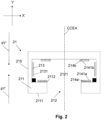
- Figure 3 shows an embodiment of the electrical connector 1 coupled with the electrical counter connector arrangement 2 in a view analogue to Figure 2 .
- the electrical counter connector element 21' of the electrical counter connector arrangement 2 belongs to a first group of counter connector elements and the electrical counter connector element 21" of the electrical counter connector arrangement 2 belongs to a second group of the counter connector elements as explained before.
- the connection axis CA represents the symmetry axis and therefore the electrical counter connector element 21' is laterally reversed to the electrical counter connector element 21".
- the main counter connector element contacts 231' of the first group of counter connector elements 21' may be electrically connected to a phase conductor of a mains connection power and the main counter connector element contacts 231" of the second group of counter connector elements 21" may be electrically connected to a neutral conductor of the mains connection.
- the main counter connector element contacts 213' of the first group of counter connector elements 21' may be electrically connected to a neutral conductor of the mains connection and the main counter connector element contacts 213" of the second group of counter connector elements 21" may are electrically connected to a phase conductor of a mains connection power.
- first 11' and second 11" electrical connector element of the electrical connector 1 point towards each other.
- the first 11' and second 11" electrical connector element may be of identical shape, dimension and design, but may also be different in another embodiment.
- the auxiliary connector element contact 114' of the first electrical connector element 11' is frontally connected with the auxiliary counter connector element contact 214a' of the of the first group of counter connector elements 21'
- the auxiliary connector element contact 114" of the second electrical connector element 11" is frontally connected with the auxiliary counter connector element contact 214a" of the second group of counter connector elements 21", as shown in Figure 3 .
- the auxiliary connection for example for data transmission or as a grounding connection for safety reason is simultaneously established with the coupling of the main contact elements.
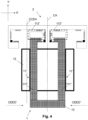
- Figure 4 shows a further embodiment of the electrical connector 1 coupled with the electrical counter connector arrangement 2 in a view analogue to Figure 3 with the counter connector element axis being aligned to the Y' direction as shown in Figure 3 .
- the first 11' and the second 11" electrical connector element are formed integrally.
- the biasing member 12 here shown as a resilient tubular element, biases the first insertion part 112' of the first electrical connector element 1 1' and the second insertion part 112" of the second electrical connector element 11" towards each other.
- the first 11' and second 11" electrical connector element are connected to and project from a base element 13.
- the connector element bodies of the first 11' and second 11" electrical connector element are favorably flexibly, e.g. elastically connected to the base element 13.
- Figure 5 shows a further embodiment of the electrical connector 1 coupled with the electrical counter connector arrangement 2 generally similar to Figure 4 .
- the first 11' and the second 11" electrical connector element are formed integrally with each other and the base element 13.
- the biasing member 12 is a spring, biasing the first insertion part 112' of the first electrical connector element 11' and the second insertion part 112" of the second electrical connector element 11" towards each other.
- the biasing member 12 may, for example be made from spring steel wire and may be a leg spring respectively torsion spring.
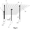
- FIG. 6 shows a schematic view of an electrical counter connector arrangement 2 containing a number of electrical devices 3.
- each of the electrical device 3 includes the electrical connector 1 and the electrical powered load 31 which may contain the lighting element 311.
- the electrical devices 3 in this embodiment are mounted in different spatially oriented directions.
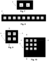
- Figure 7 shows an electrical counter connector arrangement 2 containing two electrical counter connector elements 21', 21" in a schematic top view respectively view onto the receiving apertures, as such not falling under the claim wording. This is the view that is typically visible if a counter connector arrangement 2 is mounted in a cutout of a cabinet, mounted on a wall or ceiling or the like. In the shown design, the contour of the receiving apertures of the electrical counter connector elements 21' and 21" is in each case square.
- two is generally the smallest number of counter connector elements in a counter connector arrangement 2.
- This embodiment shows exemplarily square contours of the receiving apertures of each counter connector element 21' and 21" and the electrical counter connector element 21' of the electrical counter connector arrangement 2 belongs to the first group of counter connector elements and the electrical counter connector element 21" of the electrical counter connector arrangement 2 belongs to the second group of the counter connector elements.
- Such design is suited for AC application as well as DC applications if polarity is irrelevant and allows the mounting of one electrical device.
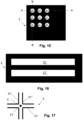
- Figure 8 shows an electrical counter connector arrangement 2 similar to Figure 7 , but with a larger number of electrical counter connector elements 21', 21", all of which are arranged in a single row. The distance between each adjacent electrical counter connector element 21' and 21" is equal. Furthermore, the electrical counter connector element 21' of the electrical counter connector arrangement 2 belongs to the first group of counter connector elements and the electrical counter connector element 21" of the electrical counter connector arrangement 2 belongs to the second group of the counter connector elements.
- Figure 9 shows a further embodiment of an electrical counter connector arrangement 2 similar to Figure 7 .
- the electrical counter connector elements 21' and 21" arranged in a 2-by-2 matrix.
- the rows A and columns B are equally distributed and the distance between the adjacent electrical counter connector elements 21 is equal.
- Figure 10 shows a further embodiment of an electrical counter connector arrangement 2 similar to Figure 9 . but with exemplarily three rows A and columns B. It is noted that the number of rows and columns may generally be chosen as desired.
- Figure 11 shows a further embodiment of an electrical counter connector arrangement 2 generally similar to Figu re 8, as such not falling under the claim wording.
- the contours of the receiving apertures of the electrical counter connector elements 21' and 21" are triangular: Like in the embodiment of Figure 8 , the distance between each adjacent electrical counter connector element 21' and 21" is equal.
- the orientation of all receiving apertures of all electrical counter connector elements 21' i.e. every second electrical counter connector element
- the orientation of all receiving apertures of all electrical counter connector elements 21" is identical, but mirrored with respect to the receiving apertures of the electrical counter connector elements 21' abut an axis along which the counter connector elements are arranged. Along this axis, electrical counter connector elements 21' and electrical counter connector elements 21" alternate with each other.
- Figure 12 shows a further embodiment of an electrical counter connector arrangement 2 similar to Figure 10 but with the counter connector elements respectively their receiving apertures being designed as shown in Figure 11 . It can be seen that counter connector elements 21' respectively 21" alternate with other within each row A and within each column B.
- Figure 15 shows a further embodiment of an electrical counter connector arrangement 2 similar to Figure 10 but with the counter connector elements respectively their receiving apertures having a circular contour.
- the connector element body in particular its distal part that is adjacent to the insertion part and forms, together with the engagement step surface the engagement step, is favorably shaped as cylinder section to allow smooth engagement with the counter connector element front member.
- Figure 13 shows an embodiment of an electrical counter connector arrangement 2 in a schematic top view containing electrical counter connector elements 21' and 21" arranged in a side-by-side matrix.
- the rows A and columns C are equally distributed and the distance between the adjacent electrical counter connector elements is equal.
- the contour of the receiving aperture of each counter connector element 21' and 21" is hexagonal and the electrical counter connector elements are connected to for a first and second group of counter connector elements as discussed before.
- Figure 14 shows a further an embodiment of an electrical counter connector arrangement 2 in a schematic top view containing electrical counter connector elements 21', 21" and 21′′′.
- the contour of the receiving aperture of each counter connector element 21', 21" and 21′′′ is hexagonal and distance between the adjacent hexagon side of the electrical counter connector elements is equal.
- the electrical counter connector elements are divided into a first group of counter connector elements 21', a second group of counter connector elements 21" and a third group of counter connector elements 21′′′.
- Such a specific embodiment may be used for electrical loads using three-phase current, e.g. at a line voltage of 400 V.
- Figure 16 shows a schematic top view of further as such not claimed embodiment of an electrical counter connector arrangement similar to Figure 7 in that two counter connector elements 21', 21" are present.
- the counter connector elements 21', 21" are elongated and extend parallel to each other.
- the shown arrangement may be extended to include generally any desired number of electrical counter connector elements belonging to a first respectively second group, by replicating the shown arrangement as desired with counter connector elements 21' belonging to the first group alternating with counter connector elements 21" belonging to the second group.
- all electrical counter connector elements may and typically are arranged equidistantly, such than an electrical connector may be with any two neighboring counter connector elements.
- a larger distance is favorably present between each pair of a counter connector element belonging to the first and second group.
- Figure 17 shows a schematic top view of a further counter connector arrangement.
- the counter connector elements 21', 21" have an in each case L-shaped contour of the receiving aperture.
- the counter connector elements 21, 21" are arranged in a centrally symmetrical manner with respect to center C.
- the two in each case diametrically opposite counter connector elements 21' respectively counter connector elements 21" form the first respectively second group of counter connector elements.
- the arrangement is such that in each case parallel legs are equidistant, thereby allowing the coupling with an electrical connector as explained before.
- the shown structure may, of course, be replicated as desired.
- the main counter connector element contacts favorably extend over substantially the whole length of the legs respectively apertures, thereby allowing coupling of an electrical connector at any desired position.
Landscapes
- Engineering & Computer Science (AREA)
- General Engineering & Computer Science (AREA)
- Details Of Connecting Devices For Male And Female Coupling (AREA)
Claims (15)
- Elektrischer Verbinder (1), insbesondere Stecker, zur Kopplung mit einer elektrischen Gegenverbinderanordnung (2) nach einem der Ansprüche 11 bis 15, wobei der elektrische Verbinder (1) ein erstes (11') und ein zweites (11") elektrisches Verbinderelement aufweist, wobei das erste (11') und das zweite (11") Verbinderelement jeweils umfassen- einen länglichen Verbinderelementkörper (111), wobei sich der Verbinderelementkörper (111) entlang einer Verbinderelementachse (CEA) erstreckt, wobei die Verbinderelementachse (CEA) eine proximale Richtung des Verbinderelements (pY) und eine distale Richtung des Verbinderelements (dY) entgegengesetzt zu der proximalen Richtung des Verbinderelements (pY) definiert,- ein Einsatzteil (112), wobei das Einsatzteil (112) distal an den Verbinderelementkörper (111) angrenzt,
wobei ein Eingriffsabsatz (1121) mit einer Eingriffsabsatzfläche (11211) an einem Übergang von dem Verbinderelementkörper (111) zu dem Einsatzteil (112) ausgebildet ist, wobei sich die Eingriffsabsatzfläche (11211) in einer Eingriffsrichtung des Verbinderelements (CEED) quer zu der Verbinderelementachse (CEA) und nach außen in Bezug auf den Verbinderelementkörper (111) erstreckt,- einen Kontakt des Hauptverbinderelements (113), wobei der Kontakt des Hauptverbinderelements (113) eine Kontaktfläche des Hauptverbinderelements (1131) aufweist, wobei die Kontaktfläche des Hauptverbinderelements (1131) an dem Einsatzteil (112) angeordnet ist,wobei die Kontaktfläche des Hauptverbinderelements (1131) durch eine Bewegung des elektrischen Verbinderelements (11) in der Eingriffsrichtung des Verbinderelements (CEED) frontal kontaktierbar ist,wobei das erste Einsatzteil (112') des ersten elektrischen Verbinderelements (11') und das zweite Einsatzteil (112") des zweiten elektrischen Verbinderelements (11") auf gegenüberliegenden Seiten in Bezug auf eine Verbinderlängsachse (CA) angeordnet sind,der elektrische Verbinder ferner ein Spannelement (12) aufweist, wobei das Spannelement (12) mit dem ersten Verbinderelementkörper (111') des ersten elektrischen Verbinderelements (11') und dem zweiten Verbinderelementkörper (111") des zweiten elektrischen Verbinderelements (11") verbunden ist,dadurch gekennzeichnet, dassdie erste Eingriffsrichtung des Verbinderelements (CEED') des ersten elektrischen Verbinderelements (11') und die zweite Eingriffsrichtung des Verbinderelements (CEED") des zweiten elektrischen Verbinderelements (11") aufeinander zu weisen, undwobei das Spannelement (12) das erste Einsatzteil (112') des ersten elektrischen Verbinderelements (11') und das zweite Einsatzteil (112") des zweiten elektrischen Verbinderelements (11") zueinander hin vorgespannt, insbesondere elastisch vorspannt, sind. - Elektrischer Verbinder (1) nach Anspruch 1, wobei ein Querschnitt des Einsatzteils (112) quer zur Verbinderelementachse (CEA) polygonal ist, insbesondere quadratisch oder rechteckig für das erste (11') und/oder das zweite (11") Verbinderelement.
- Elektrischer Verbinder (1) nach einem der vorhergehenden Ansprüche, wobei die Kontaktfläche des Hauptverbinderelements (1131) für das erste (11') und/oder das zweite (11") Verbinderelement planar ist.
- Elektrischer Verbinder (1) nach einem der vorhergehenden Ansprüche, wobei das elektrische Verbinderelement (11) des ersten Verbinderelements (11') und/oder des zweiten Verbinderelements (11") ferner einen oder mehrere Kontakte des Hilfsverbinderelements (114) aufweist, die von dem Kontakt des Hauptverbinderelements (113) verschieden sind, wobei die Kontakte des Hilfsverbinderelements (114) jeweils eine entsprechende Kontaktfläche des Hilfsverbinderelements (1141) aufweisen, die an dem Einsatzteil (112) angeordnet ist.
- Elektrischer Verbinder (1) nach Anspruch 4, wobei mindestens eine Kontaktfläche des Hilfsverbinderelements (1141) an der Eingriffsabsatzfläche (11211) für das erste (11') und/oder das zweite (11") Verbinderelement (11") angeordnet ist.
- Elektrischer Verbinder (1) nach einem der vorhergehenden Ansprüche, wobei für das erste (11') und/oder das zweite (11") Verbinderelement ein Hauptverbinderelement-Kopplungsleiter, insbesondere ein Hauptverbinderelement-Kopplungsdraht (115), elektrisch mit dem Kontakt des Hauptverbinderelements (113) verbunden ist, wobei der Hauptverbinderelement-Kopplungsleiter durch eine Öffnung (1151) an der proximalen Seite des Verbinderelementkörpers (111) geführt ist.
- Elektrischer Verbinder (1) nach einem der vorhergehenden Ansprüche, wobei der Kontakt des Hauptverbinderelements (113) für einen maximalen Strom von 1A, 10A oder 16A für das erste (11') und das zweite (11") Verbinderelement ausgelegt ist.
- Elektrischer Verbinder (1) nach einem der vorhergehenden Ansprüche, wobei das erste (112') und das zweite (112") Einsatzteil von identischer Konstruktion und Abmessung sind.
- Elektrischer Verbinder (1) nach einem der vorhergehenden Ansprüche, wobei der elektrische Verbinder (1) für eine elektrische Spannung zwischen dem ersten Kontakt des Hauptverbinderelements (113') des ersten elektrischen Verbinderelements (11') und dem zweiten Kontakt des Hauptverbinderelements (113") des zweiten Kontaktelements (11") von 5VDC, 12VDC, 24VDC, 11OVAC, 230VAC ausgelegt ist.
- Elektrische Vorrichtung (3), wobei die elektrische Vorrichtung (3) eine elektrisch betriebene Last (31) enthält, wobei die elektrisch betriebene Last (31) insbesondere mindestens ein Beleuchtungselement (311) enthält, wobei die elektrische Vorrichtung (3) ferner einen elektrischen Verbinder (1) nach einem der vorhergehenden Ansprüche enthält, wobei der elektrische Verbinder (1) mit der elektrisch betriebenen Last (31) verbunden ist, um die elektrisch betriebene Last (31) mit elektrischer Energie zu versorgen.
- Elektrische Gegenverbinderanordnung (2), insbesondere Buchsenanordnung, zur Kopplung mit einem elektrischen Verbinder (1) nach einem der Ansprüche 1 bis 9, wobei die elektrische Gegenverbinderanordnung (2) eine Anzahl von elektrischen Gegenverbinderelementen (21), insbesondere Buchsenelementen, aufweist, wobei die Gegenverbinderelemente jeweils umfassen- ein Gegenverbinderfrontelement (211), wobei das Gegenverbinderfrontelement (211) eine proximale Frontelementseite (2111) und eine dazu parallele distale Frontelementseite (2112) aufweist,- eine Aufnahmeöffnung (212), wobei sich die Aufnahmeöffnung (212) kontinuierlich zwischen der proximalen (2111) und distalen (2112) Frontelementseite erstreckt, wobei sich eine Gegenverbinderelementsachse (CCEA) durch die Aufnahmeöffnung (212) erstreckt, wobei die Gegenverbinderelementsachse (CCEA) eine proximale Richtung des Gegenverbinderelements (pY') und eine distale Richtung des Gegenverbinderelements (dY') entgegengesetzt zur proximalen Richtung des Gegenverbinderelements (pY') definiert,
wobei die Aufnahmeöffnung (212) in einen Aufnahmeraum (2121) mündet, der von dem Gegenverbinderfrontelement (211) distal angeordnet ist, wobei der Aufnahmeraum (2121) dazu konfiguriert ist, das Einsatzteil (112) über die Aufnahmeöffnung (212) aufzunehmen,- einen Kontakt des Hauptgegenverbinderelements (213), wobei der Kontakt des Hauptgegenverbinderelements (213) distal von dem Gegenverbinderfrontelement (211) angeordnet ist,der Kontakt des Hauptgegenverbinderelements (213) eine Kontaktfläche des Hauptgegenverbinderelements (2131) aufweist,wobei die Kontaktfläche des Hauptgegenverbinderelements (2131) seitlich gegenüber der Aufnahmeöffnung (212) zurückversetzt angeordnet ist,die Kontaktfläche des Hauptgegenverbinderelements (2131) den Aufnahmeraum (2121) seitlich begrenzt,so dass durch Einführen des Einsatzteils (112) in den Aufnahmeraum (2121) über die Aufnahmeöffnung (212) in der distalen Richtung des Gegenverbinderelements (dY') und anschließendes Verschieben des elektrischen Verbinderelements (21) in der Eingriffsrichtung des Verbinderelements (CEED) das Gegenverbinderfrontelement (211) in den Eingriffsabsatz des Verbinderelements (1121) eingreift und die Kontaktfläche des Hauptverbinderelements (1131) die Kontaktfläche des Hauptgegenverbinderelements (2131) elektrisch kontaktiert,wobei die elektrischen Gegenverbinderelemente (21) in eine erste Gruppe von Gegenverbinderelementen (21') und eine zweite Gruppe von Gegenverbinderelementen (21") unterteilt sind,dadurch gekennzeichnet, dass die Hauptkontakte des elektrischen Verbinderelements (213') aller elektrischen Gegenverbinderelemente (21'), die zu der ersten Gruppe gehören, untereinander elektrisch verbunden sind, jedoch nicht mit den Kontakten des Hauptgegenverbinderelements (213") der Verbinderelemente (21"), die zu der zweiten Gruppe gehören,und wobei die Hauptkontakte des elektrischen Gegenverbinderelements (213") aller elektrischen Verbinderelemente (21"), die zu der zweiten Gruppe gehören, untereinander elektrisch verbunden sind, jedoch nicht mit den Kontakten des Hauptverbindergegenelements (213') der Verbinderelemente (21'), die zu der ersten Gruppe gehören,wobei die elektrischen Verbinderelemente (21', 21") als Matrix aus Reihen (A) und Spalten (B) nebeneinander angeordnet sind, wobei die Reihen (A) und die Spalten (B) gleich verteilt sind und ein Abstand zwischen benachbarten Reihen (A) dem Abstand zwischen benachbarten Spalten (B) entspricht, wobei innerhalb jeder Reihe (A) und jeder Spalte (B) zur ersten Gruppe gehörende Verbinderelemente (21') mit zur zweiten Gruppe gehörenden Verbinderelementen (21") abwechselnd angeordnet sind. - Elektrische Gegenverbinderanordnung (2) nach Anspruch 11, wobei für jedes Gegenverbinderelement (21) die Kontaktfläche des Hauptgegenverbinderelements (213) in Bezug auf die Aufnahmeöffnung (212) in Umfangsrichtung kontinuierlich ist oder eine Anzahl von Kontaktflächenabschnitten des Hauptgegenverbinderelements umfasst, wobei die Kontaktflächenabschnitte des Hauptgegenverbinderelements in Umfangsrichtung um die Aufnahmeöffnung (212) herum verteilt angeordnet sind.
- Elektrische Gegenverbinderanordnung (2) nach Anspruch 11 oder 12, wobei für jedes Gegenverbinderelement (21) eine Kontur der Aufnahmeöffnung (212) polygonal, insbesondere quadratisch oder rechteckig ist.
- Elektrische Gegenverbinderanordnung (2) nach einem der Ansprüche 11 bis 13, wobei jedes elektrische Verbinderelement (21) ferner einen oder mehrere Hilfskontakte des Gegenverbinderelements (214a, 214b) aufweist, die sich von dem Kontakt des Hauptgegenverbinderelements (213) unterscheiden, wobei die Hilfskontakte des Gegenverbinderelements (214a, 214b) distal von dem Gegenverbinderfrontelement (211) angeordnet sind.
- Elektrische Gegenverbinderanordnung (2) nach einem der Ansprüche 11 bis 14, wobei die Kontakte des Hauptgegenverbinderelements (213'), die zu der ersten Gruppe von Gegenverbinderelementen (21') gehören, so konfiguriert sind, dass sie elektrisch mit einem Phasenleiter einer Netzanschlussleistung verbunden sind, und die Kontakte des Hauptgegenverbinderelements (213"), die zu der zweiten Gruppe von Gegenverbinderelementen (21") gehören, so konfiguriert sind, dass sie elektrisch mit einem Nullleiter des Netzanschlusses verbunden sind.
Priority Applications (4)
| Application Number | Priority Date | Filing Date | Title |
|---|---|---|---|
| EP21189826.7A EP4131670B1 (de) | 2021-08-05 | 2021-08-05 | Elektrische steckverbindung und gegenstecker |
| US18/293,404 US20240332875A1 (en) | 2021-08-05 | 2022-08-04 | Electrical connector and counter connector |
| PCT/EP2022/071949 WO2023012276A1 (en) | 2021-08-05 | 2022-08-04 | Electrical connector and counter connector |
| EP22761508.5A EP4381228A1 (de) | 2021-08-05 | 2022-08-04 | Elektrischer verbinder und gegenverbinder |
Applications Claiming Priority (1)
| Application Number | Priority Date | Filing Date | Title |
|---|---|---|---|
| EP21189826.7A EP4131670B1 (de) | 2021-08-05 | 2021-08-05 | Elektrische steckverbindung und gegenstecker |
Publications (3)
| Publication Number | Publication Date |
|---|---|
| EP4131670A1 EP4131670A1 (de) | 2023-02-08 |
| EP4131670C0 EP4131670C0 (de) | 2025-06-04 |
| EP4131670B1 true EP4131670B1 (de) | 2025-06-04 |
Family
ID=77226673
Family Applications (2)
| Application Number | Title | Priority Date | Filing Date |
|---|---|---|---|
| EP21189826.7A Active EP4131670B1 (de) | 2021-08-05 | 2021-08-05 | Elektrische steckverbindung und gegenstecker |
| EP22761508.5A Pending EP4381228A1 (de) | 2021-08-05 | 2022-08-04 | Elektrischer verbinder und gegenverbinder |
Family Applications After (1)
| Application Number | Title | Priority Date | Filing Date |
|---|---|---|---|
| EP22761508.5A Pending EP4381228A1 (de) | 2021-08-05 | 2022-08-04 | Elektrischer verbinder und gegenverbinder |
Country Status (3)
| Country | Link |
|---|---|
| US (1) | US20240332875A1 (de) |
| EP (2) | EP4131670B1 (de) |
| WO (1) | WO2023012276A1 (de) |
Families Citing this family (2)
| Publication number | Priority date | Publication date | Assignee | Title |
|---|---|---|---|---|
| WO2024018799A1 (ja) * | 2022-07-19 | 2024-01-25 | パナソニックIpマネジメント株式会社 | 直流配電システム |
| DE102023109746A1 (de) * | 2023-04-18 | 2024-10-24 | Novem Car Interior Design Gmbh | Formteil |
Family Cites Families (9)
| Publication number | Priority date | Publication date | Assignee | Title |
|---|---|---|---|---|
| US2441461A (en) * | 1945-11-19 | 1948-05-11 | Wayne Anthony | Electric utility connection |
| US3089042A (en) * | 1959-01-26 | 1963-05-07 | Ite Circuit Breaker Ltd | Continuous outlet surface extension assembly |
| GB1000925A (en) * | 1963-05-21 | 1965-08-11 | Lightolier Inc | Improvements in or relating to electric current conducting devices |
| US4822292A (en) * | 1985-01-02 | 1989-04-18 | Thayer George F | Multiple line circuit track lighting system and fixture mounting adapters therefore |
| DE4302560C1 (de) * | 1993-01-29 | 1994-04-07 | Horst Lettenmayer | Galerielichtleiste |
| GB2278964B (en) * | 1993-06-04 | 1996-12-04 | Wei Hong Shen | Track-mounted lighting fixture |
| BR9509335A (pt) * | 1994-10-14 | 1998-01-27 | Sinclair John Asthon | Condutor elétrico flexível alongado conjunto de condutor e de duto elétrico membro isolante alongado para um condutor elétrico eletrocalha e isolador elétrico |
| US7982436B2 (en) * | 2002-12-10 | 2011-07-19 | Pure Energy Solutions, Inc. | Battery cover with contact-type power receiver for electrically powered device |
| US9130327B2 (en) * | 2013-06-18 | 2015-09-08 | Trinity, Llc | Power assembly for display |
-
2021
- 2021-08-05 EP EP21189826.7A patent/EP4131670B1/de active Active
-
2022
- 2022-08-04 WO PCT/EP2022/071949 patent/WO2023012276A1/en not_active Ceased
- 2022-08-04 US US18/293,404 patent/US20240332875A1/en active Pending
- 2022-08-04 EP EP22761508.5A patent/EP4381228A1/de active Pending
Also Published As
| Publication number | Publication date |
|---|---|
| EP4131670C0 (de) | 2025-06-04 |
| US20240332875A1 (en) | 2024-10-03 |
| EP4131670A1 (de) | 2023-02-08 |
| EP4381228A1 (de) | 2024-06-12 |
| WO2023012276A1 (en) | 2023-02-09 |
Similar Documents
| Publication | Publication Date | Title |
|---|---|---|
| EP4131670B1 (de) | Elektrische steckverbindung und gegenstecker | |
| JP6316301B2 (ja) | 低電圧バスシステム | |
| WO2004074741A2 (en) | Field bendable line voltage track lighting system | |
| WO2003084819A3 (en) | A low volatage electricity distribution circuit | |
| EP2591283B1 (de) | Starres niederspannungskabel | |
| US20070105414A1 (en) | Swivellable electric socket-plug combination | |
| EP2856573A1 (de) | Verbinderanordnung mit polaritätskorrektur/-schutz | |
| CN113922429A (zh) | 用于ac和dc共同配电的设备和方法 | |
| US20150322987A1 (en) | Cable tray segments with integrated splice plates | |
| CN100349331C (zh) | 可旋转的插头和插座 | |
| US20180301908A1 (en) | Driver with Pass-Through AC Outlet | |
| US20220015541A1 (en) | System for a presentation, sales or exhibition stand and/or for store fitting, as well as current-carrying wall member in such a system | |
| KR200282469Y1 (ko) | 전원 연결용 케이블 컨넥터 | |
| CN110582907B (zh) | 多馈汇流条系统 | |
| US10364945B2 (en) | Electrical wall receptacle, LED module, and lamp system | |
| KR20080096070A (ko) | 멀티탭 | |
| WO2024157086A2 (en) | Residential dc voltage infrastructure | |
| CN121241491A (zh) | 配线槽和配线槽系统 | |
| EP3254343B1 (de) | Vorrichtung zur verteilung und nutzung elektrischer energie | |
| CN202405435U (zh) | 母线槽的导电连接端子 | |
| US20180337494A1 (en) | Electric power distribution module and system | |
| HK1115506B (en) | Swivellable electric socket-plug combination | |
| CN108758579A (zh) | 一种可灵活布设的电路装置 | |
| AU2014201102A1 (en) | Electrified ceiling framework underside connectors |
Legal Events
| Date | Code | Title | Description |
|---|---|---|---|
| PUAI | Public reference made under article 153(3) epc to a published international application that has entered the european phase |
Free format text: ORIGINAL CODE: 0009012 |
|
| STAA | Information on the status of an ep patent application or granted ep patent |
Free format text: STATUS: THE APPLICATION HAS BEEN PUBLISHED |
|
| AK | Designated contracting states |
Kind code of ref document: A1 Designated state(s): AL AT BE BG CH CY CZ DE DK EE ES FI FR GB GR HR HU IE IS IT LI LT LU LV MC MK MT NL NO PL PT RO RS SE SI SK SM TR |
|
| P01 | Opt-out of the competence of the unified patent court (upc) registered |
Effective date: 20230512 |
|
| STAA | Information on the status of an ep patent application or granted ep patent |
Free format text: STATUS: REQUEST FOR EXAMINATION WAS MADE |
|
| 17P | Request for examination filed |
Effective date: 20230721 |
|
| RBV | Designated contracting states (corrected) |
Designated state(s): AL AT BE BG CH CY CZ DE DK EE ES FI FR GB GR HR HU IE IS IT LI LT LU LV MC MK MT NL NO PL PT RO RS SE SI SK SM TR |
|
| REG | Reference to a national code |
Ref legal event code: R079 Ipc: H01R0025140000 Ref country code: DE Ref legal event code: R079 Ref document number: 602021031645 Country of ref document: DE Free format text: PREVIOUS MAIN CLASS: H01R0024000000 Ipc: H01R0025140000 |
|
| GRAP | Despatch of communication of intention to grant a patent |
Free format text: ORIGINAL CODE: EPIDOSNIGR1 |
|
| STAA | Information on the status of an ep patent application or granted ep patent |
Free format text: STATUS: GRANT OF PATENT IS INTENDED |
|
| RIC1 | Information provided on ipc code assigned before grant |
Ipc: F21S 8/06 20060101ALN20241226BHEP Ipc: H01R 25/16 20060101ALN20241226BHEP Ipc: F21V 23/06 20060101ALI20241226BHEP Ipc: F21V 21/35 20060101ALI20241226BHEP Ipc: H01R 24/00 20110101ALI20241226BHEP Ipc: H01R 25/14 20060101AFI20241226BHEP |
|
| INTG | Intention to grant announced |
Effective date: 20250110 |
|
| GRAS | Grant fee paid |
Free format text: ORIGINAL CODE: EPIDOSNIGR3 |
|
| GRAA | (expected) grant |
Free format text: ORIGINAL CODE: 0009210 |
|
| STAA | Information on the status of an ep patent application or granted ep patent |
Free format text: STATUS: THE PATENT HAS BEEN GRANTED |
|
| AK | Designated contracting states |
Kind code of ref document: B1 Designated state(s): AL AT BE BG CH CY CZ DE DK EE ES FI FR GB GR HR HU IE IS IT LI LT LU LV MC MK MT NL NO PL PT RO RS SE SI SK SM TR |
|
| REG | Reference to a national code |
Ref country code: GB Ref legal event code: FG4D |
|
| REG | Reference to a national code |
Ref country code: CH Ref legal event code: EP |
|
| REG | Reference to a national code |
Ref country code: DE Ref legal event code: R096 Ref document number: 602021031645 Country of ref document: DE |
|
| REG | Reference to a national code |
Ref country code: IE Ref legal event code: FG4D |
|
| U01 | Request for unitary effect filed |
Effective date: 20250605 |
|
| P04 | Withdrawal of opt-out of the competence of the unified patent court (upc) registered |
Free format text: CASE NUMBER: APP_27729/2025 Effective date: 20250610 |
|
| U07 | Unitary effect registered |
Designated state(s): AT BE BG DE DK EE FI FR IT LT LU LV MT NL PT RO SE SI Effective date: 20250613 |
|
| U20 | Renewal fee for the european patent with unitary effect paid |
Year of fee payment: 5 Effective date: 20250827 |
|
| PG25 | Lapsed in a contracting state [announced via postgrant information from national office to epo] |
Ref country code: ES Free format text: LAPSE BECAUSE OF FAILURE TO SUBMIT A TRANSLATION OF THE DESCRIPTION OR TO PAY THE FEE WITHIN THE PRESCRIBED TIME-LIMIT Effective date: 20250604 |
|
| REG | Reference to a national code |
Ref country code: CH Ref legal event code: R14 Free format text: ST27 STATUS EVENT CODE: U-0-0-R10-R14 (AS PROVIDED BY THE NATIONAL OFFICE) Effective date: 20251009 |
|
| PG25 | Lapsed in a contracting state [announced via postgrant information from national office to epo] |
Ref country code: NO Free format text: LAPSE BECAUSE OF FAILURE TO SUBMIT A TRANSLATION OF THE DESCRIPTION OR TO PAY THE FEE WITHIN THE PRESCRIBED TIME-LIMIT Effective date: 20250904 Ref country code: GR Free format text: LAPSE BECAUSE OF FAILURE TO SUBMIT A TRANSLATION OF THE DESCRIPTION OR TO PAY THE FEE WITHIN THE PRESCRIBED TIME-LIMIT Effective date: 20250905 |
|
| PG25 | Lapsed in a contracting state [announced via postgrant information from national office to epo] |
Ref country code: PL Free format text: LAPSE BECAUSE OF FAILURE TO SUBMIT A TRANSLATION OF THE DESCRIPTION OR TO PAY THE FEE WITHIN THE PRESCRIBED TIME-LIMIT Effective date: 20250604 |
|
| PG25 | Lapsed in a contracting state [announced via postgrant information from national office to epo] |
Ref country code: HR Free format text: LAPSE BECAUSE OF FAILURE TO SUBMIT A TRANSLATION OF THE DESCRIPTION OR TO PAY THE FEE WITHIN THE PRESCRIBED TIME-LIMIT Effective date: 20250604 |
|
| PGFP | Annual fee paid to national office [announced via postgrant information from national office to epo] |
Ref country code: CH Payment date: 20250901 Year of fee payment: 5 |
|
| PG25 | Lapsed in a contracting state [announced via postgrant information from national office to epo] |
Ref country code: RS Free format text: LAPSE BECAUSE OF FAILURE TO SUBMIT A TRANSLATION OF THE DESCRIPTION OR TO PAY THE FEE WITHIN THE PRESCRIBED TIME-LIMIT Effective date: 20250904 |
|
| REG | Reference to a national code |
Ref country code: CH Ref legal event code: Y10 Free format text: ST27 STATUS EVENT CODE: U-0-0-Y10-Y00 (AS PROVIDED BY THE NATIONAL OFFICE) Effective date: 20251105 |
|
| RAP2 | Party data changed (patent owner data changed or rights of a patent transferred) |
Owner name: ITSCHNER CONNECT AG |
|
| RIN2 | Information on inventor provided after grant (corrected) |
Inventor name: ITSCHNER, ROLAND |
|
| U1K | Transfer of rights of the unitary patent after the registration of the unitary effect |
Owner name: ITSCHNER CONNECT AG; CH |