EP4131669A1 - Rotary plug connector - Google Patents
Rotary plug connector Download PDFInfo
- Publication number
- EP4131669A1 EP4131669A1 EP22187294.8A EP22187294A EP4131669A1 EP 4131669 A1 EP4131669 A1 EP 4131669A1 EP 22187294 A EP22187294 A EP 22187294A EP 4131669 A1 EP4131669 A1 EP 4131669A1
- Authority
- EP
- European Patent Office
- Prior art keywords
- plug
- contacts
- socket
- power
- electrical connector
- Prior art date
- Legal status (The legal status is an assumption and is not a legal conclusion. Google has not performed a legal analysis and makes no representation as to the accuracy of the status listed.)
- Granted
Links
Images




Classifications
-
- H—ELECTRICITY
- H01—ELECTRIC ELEMENTS
- H01R—ELECTRICALLY-CONDUCTIVE CONNECTIONS; STRUCTURAL ASSOCIATIONS OF A PLURALITY OF MUTUALLY-INSULATED ELECTRICAL CONNECTING ELEMENTS; COUPLING DEVICES; CURRENT COLLECTORS
- H01R13/00—Details of coupling devices of the kinds covered by groups H01R12/70 or H01R24/00 - H01R33/00
- H01R13/66—Structural association with built-in electrical component
- H01R13/70—Structural association with built-in electrical component with built-in switch
- H01R13/71—Contact members of coupling parts operating as switch, e.g. linear or rotational movement required after mechanical engagement of coupling part to establish electrical connection
-
- H—ELECTRICITY
- H01—ELECTRIC ELEMENTS
- H01R—ELECTRICALLY-CONDUCTIVE CONNECTIONS; STRUCTURAL ASSOCIATIONS OF A PLURALITY OF MUTUALLY-INSULATED ELECTRICAL CONNECTING ELEMENTS; COUPLING DEVICES; CURRENT COLLECTORS
- H01R13/00—Details of coupling devices of the kinds covered by groups H01R12/70 or H01R24/00 - H01R33/00
- H01R13/02—Contact members
- H01R13/10—Sockets for co-operation with pins or blades
- H01R13/11—Resilient sockets
-
- H—ELECTRICITY
- H01—ELECTRIC ELEMENTS
- H01R—ELECTRICALLY-CONDUCTIVE CONNECTIONS; STRUCTURAL ASSOCIATIONS OF A PLURALITY OF MUTUALLY-INSULATED ELECTRICAL CONNECTING ELEMENTS; COUPLING DEVICES; CURRENT COLLECTORS
- H01R13/00—Details of coupling devices of the kinds covered by groups H01R12/70 or H01R24/00 - H01R33/00
- H01R13/46—Bases; Cases
- H01R13/502—Bases; Cases composed of different pieces
-
- H—ELECTRICITY
- H01—ELECTRIC ELEMENTS
- H01R—ELECTRICALLY-CONDUCTIVE CONNECTIONS; STRUCTURAL ASSOCIATIONS OF A PLURALITY OF MUTUALLY-INSULATED ELECTRICAL CONNECTING ELEMENTS; COUPLING DEVICES; CURRENT COLLECTORS
- H01R24/00—Two-part coupling devices, or either of their cooperating parts, characterised by their overall structure
- H01R24/005—Two-part coupling devices, or either of their cooperating parts, characterised by their overall structure requiring successive relative motions to complete the coupling, e.g. bayonet type
-
- H—ELECTRICITY
- H01—ELECTRIC ELEMENTS
- H01R—ELECTRICALLY-CONDUCTIVE CONNECTIONS; STRUCTURAL ASSOCIATIONS OF A PLURALITY OF MUTUALLY-INSULATED ELECTRICAL CONNECTING ELEMENTS; COUPLING DEVICES; CURRENT COLLECTORS
- H01R24/00—Two-part coupling devices, or either of their cooperating parts, characterised by their overall structure
- H01R24/76—Two-part coupling devices, or either of their cooperating parts, characterised by their overall structure with sockets, clips or analogous contacts and secured to apparatus or structure, e.g. to a wall
-
- H—ELECTRICITY
- H01—ELECTRIC ELEMENTS
- H01R—ELECTRICALLY-CONDUCTIVE CONNECTIONS; STRUCTURAL ASSOCIATIONS OF A PLURALITY OF MUTUALLY-INSULATED ELECTRICAL CONNECTING ELEMENTS; COUPLING DEVICES; CURRENT COLLECTORS
- H01R13/00—Details of coupling devices of the kinds covered by groups H01R12/70 or H01R24/00 - H01R33/00
- H01R13/62—Means for facilitating engagement or disengagement of coupling parts or for holding them in engagement
- H01R13/625—Casing or ring with bayonet engagement
-
- H—ELECTRICITY
- H01—ELECTRIC ELEMENTS
- H01R—ELECTRICALLY-CONDUCTIVE CONNECTIONS; STRUCTURAL ASSOCIATIONS OF A PLURALITY OF MUTUALLY-INSULATED ELECTRICAL CONNECTING ELEMENTS; COUPLING DEVICES; CURRENT COLLECTORS
- H01R2101/00—One pole
-
- H—ELECTRICITY
- H01—ELECTRIC ELEMENTS
- H01R—ELECTRICALLY-CONDUCTIVE CONNECTIONS; STRUCTURAL ASSOCIATIONS OF A PLURALITY OF MUTUALLY-INSULATED ELECTRICAL CONNECTING ELEMENTS; COUPLING DEVICES; CURRENT COLLECTORS
- H01R24/00—Two-part coupling devices, or either of their cooperating parts, characterised by their overall structure
- H01R24/38—Two-part coupling devices, or either of their cooperating parts, characterised by their overall structure having concentrically or coaxially arranged contacts
Definitions
- Plug connectors are used to connect an electrical power source such as a battery to one or more modules.
- Such connectors typically include a plug and socket having separate power and signal contacts, respectively, to connect both electrical power such as current and a signal such as data.
- Rotation of the plug relative to the socket operates the connector between on and off positions. That is, in a first position, the signal contacts between the plug and socket are disconnected. Rotating the plug to a second position bridges the signal contact of the socket with a contact of the plug to deliver signals.
- the signals may be used to control power in and power out from the power source to a module via the power contacts of the plug and socket.
- the present invention relates to an improved plug connector in which the power contacts of the plug have a simpler construction and provide a reliable power connection.
- Rotary plug connectors for electrical assemblies are well-known in the prior art as evidenced by CN104426004 in which a plug is arranged in a socket and rotated between on and off positions.
- the socket contains a pair of spaced tulip power contacts and a central tulip signal contact while the plug contains a pair of pin or blade power contacts and a central pin signal contact.
- the pin or blade power connectors slide relative to the tulip power contacts and the center signal contacts of the plug and socket are connected to deliver a signal and control the delivery of power from a power source to a module.
- the socket tulip contacts must have an arcuate configuration. Such contacts are difficult to manufacture and require precision during assembly. Moreover, because of their flexible nature, the socket tulip contacts may be bent or damaged during repetitive rotation of the plug between its on and off position as the plug pin or blade contacts slide through the socket contacts. This diminishes the reliability of such plug connectors over time.
- the present invention was developed in order to overcome these and other drawbacks of prior rotary plug connectors by providing a plug assembly in which the socket power contacts are configured as durable blades and the plug power contacts are configured as spring blade contacts which remain within and connected with the socket contacts during rotation of the plug relative to the socket.
- a rotary electrical connector assembly including a socket having a receptacle which contains a power contact assembly including a pair of spaced opposed contacts and a central signal contact assembly.
- the opposed contacts of the socket power contact assembly have either planar or concave contact surfaces.
- a plug is arranged within the socket receptacle.
- the plug is configured for rotary movement between operable and inoperable positions relative to the socket and includes a power contact assembly which includes a plurality of spaced blade contacts which are configured to engage the socket power contacts and a signal bridge which engages the socket signal contact assembly when the plug is in the operable position and which disengages from the socket signal contact assembly when the plug is in the inoperable position.
- the plug power contact assembly includes a central portion and opposed pairs of spaced parallel blade contacts which extend outwardly from the central portion, each pair of blade contacts at least partially engaging the opposed socket power contacts when the plug is rotated between the operable and inoperable positions.
- the plug power contacts have either an S-shaped or a U-shaped cross-sectional configuration.
- the socket signal contact assembly preferably includes a pair of spaced parallel contacts.
- the plug signal bridge contact is configured to engage the free ends of the socket signal contacts when the plug is in the operable position.
- the electrical connector assembly 2 includes a plug 4 and socket 6.
- the socket includes a receptacle 8 in which the plug is arranged as shown in Fig. 5 .
- the plug is configured for rotation within the socket receptacle.
- the plug includes a generally cylindrical housing 10 which is formed of a durable rigid material such as synthetic plastic.
- the plug includes an inner chamber 12 (shown in Fig. 5 ) within which is arranged a power contact assembly 14.
- a cover 16 is provided to close the bottom of the plug chamber. Arranged within the cover is a signal bridge contact 18.
- the socket 6 of the connector assembly is shown in Fig. 4 . It includes a cylindrical housing 20 formed of non-conductive material such as synthetic plastic which contains the receptacle. The inner diameter of the receptacle corresponds with the outer diameter of the plug housing with a limited amount of play to allow the plug to rotate within the socket receptacle. An O-ring or other circular seal 22 is provided between the upper edge of the socket housing and the lower surface of the plug housing. A pair of power contacts 24 are connected with the socket housing by suitable fasteners such as a pair of bolts (not shown) which cooperate with nuts 26.
- the socket power contacts are formed of a durable and preferably rigid conductive material such as metal. They preferably have an L-shaped configuration with the lower portions 24a thereof being connected with the socket housing.
- the upper portions 24b of the socket power contacts extend upwardly into the socket receptacle in spaced relation as shown in Fig. 5 .
- the upper portions of the socket power contacts have opposed parallel planar surfaces which are engaged by the power contact assembly 14 of the plug as will be developed below.
- the socket further includes a central signal contact assembly 28 arranged between the power contact.
- the signal contact assembly is preferably centrally arranged within the socket housing and includes a spaced pair of contacts 28a arranged on opposite sides of the socket axis.
- the socket further includes additional seals 30 and fasteners 32 for connection with additional components or modules.
- the plug power contact assembly 14 has a central portion 14a from which a plurality of opposed pairs of spaced parallel blade contacts 14b extend outwardly.
- the blade contacts are formed of a conductive material such as metal and preferably have a resilient spring-like nature.
- the contact assembly has an S-shaped cross-sectional configuration.
- Such a blade assembly is also shown in Figs. 6 and 7 which illustrate the plug in its operable and inoperable positions, respectively.
- the plug housing includes an internal slot or channel within which the central portion 14a of the plug power contact assembly is retained. As shown in Fig.
- each blade 14a of the plug power contact assembly engages a planar surface of the adjacent socket power contact portion 24b.
- a lesser portion of each blade 14b of the plug power contact assembly engages a planar surface of the adjacent socket power contact.
- the blade power contacts of the plug are arranged within and biased against the socket power contacts owing to the spring force within the blades.
- the signal bridge contact 18 of the plug engages the upper ends of the socket signal contacts 28a to provide an electrical connection therebetween. More particularly, the bridge signal contact 18 has a U-shaped cross-sectional configuration. The upper ends at opposite sides of the bridge contact the upper edges of the socket signal contacts.
- the plug bridge signal contact is rotated out of engagement with the socket signal contacts 28a to electrically and mechanically disconnect the plug and socket signal contacts.
- signals transmitted between the plug and socket enable the power contacts between the plug and socket to transmit power or electrical current through the connector assembly.
- the connector assembly is arranged between a power source such as a battery and an electrical component or module, the connector assembly supplies power from the source to the component when the plug is rotated to the operable position.
- the plug and signal contacts are disconnected. This prevents power transfer between the plug and signal power contacts, even if they remain at least partially connected. Accordingly, in the inoperable position, the connector assembly prevents "hot" plugging of the connection between the power contacts.
- the power contact assembly 114 has a U-shaped configuration including a central portion 114a from which a plurality of spaced parallel blade contacts 114b extend. The oppositely extending contacts abut against the planar surfaces of the opposed socket power contacts portions 24b as shown in Fig. 13 .
- the socket power contacts are preferably rigid while the plug power blade contacts have a resilient structure which can be deformed or compressed by rotation of the plug to the operable position and which return to a normal configuration by rotation of the plug to the inoperable position. The blade contacts slide along the planar surfaces of the socket power connectors during rotation of the plug.
- biasing springs 34 may be provided between the ends of opposed contacts 114b as shown in Fig. 14 .
- a further configuration for the plug power contact assembly 214 is shown. It is similar to that of Fig. 10 except that the pairs of spaced parallel blade contacts 214b have alternating contacts which extend from the central portion 214a at first and second distances, the second distance extending to an opposite end of the central portion.
- the blade contacts 314b of the plug power contact assembly 314 also alternate and extend at different distances, but no blade contacts extend to an opposite end of the central portion 314a.
- Fig. 18 shows an alternate configuration for a socket power contact 124.
- the contact has an L-shaped configuration including a first or base portion 124a containing an opening for receiving a fastener for connection with a socket housing and a second contact portion 124b.
- the contact portion 124b has a concave configuration to define a curved surface for contact by the plug blade contacts. The concave configuration enables the plug blade contacts to slide along the socket contact portion 124b during movement between the operable and inoperable positions.
- the socket and rotary plug connector assembly is more durable than prior rotary plug connectors in that the socket power contacts are formed of a durable metal material which is not prone to damage through use as is the case with tulip power contacts.
- the blade contacts of the plug power contact assembly are also more durable than pin power contacts of the prior devices.
- the blade contacts of the plug are arranged within or between the socket power contacts. Thus, if damage to the blade contacts occurs, the plug may be easily removed and replaced with a new plug without having to replace the socket or the entire connector assembly.
Landscapes
- Connector Housings Or Holding Contact Members (AREA)
- Details Of Connecting Devices For Male And Female Coupling (AREA)
Abstract
Description
- Plug connectors are used to connect an electrical power source such as a battery to one or more modules. Such connectors typically include a plug and socket having separate power and signal contacts, respectively, to connect both electrical power such as current and a signal such as data. Rotation of the plug relative to the socket operates the connector between on and off positions. That is, in a first position, the signal contacts between the plug and socket are disconnected. Rotating the plug to a second position bridges the signal contact of the socket with a contact of the plug to deliver signals. The signals may be used to control power in and power out from the power source to a module via the power contacts of the plug and socket.
- The present invention relates to an improved plug connector in which the power contacts of the plug have a simpler construction and provide a reliable power connection.
- Rotary plug connectors for electrical assemblies are well-known in the prior art as evidenced by
CN104426004 in which a plug is arranged in a socket and rotated between on and off positions. The socket contains a pair of spaced tulip power contacts and a central tulip signal contact while the plug contains a pair of pin or blade power contacts and a central pin signal contact. When the plug is rotated, the pin or blade power connectors slide relative to the tulip power contacts and the center signal contacts of the plug and socket are connected to deliver a signal and control the delivery of power from a power source to a module. - While the prior devices operate satisfactorily, they possess certain inherent drawbacks. That is, to maintain the power contacts between the plug and socket electrically connected during rotation of the plug relative to the socket, the socket tulip contacts must have an arcuate configuration. Such contacts are difficult to manufacture and require precision during assembly. Moreover, because of their flexible nature, the socket tulip contacts may be bent or damaged during repetitive rotation of the plug between its on and off position as the plug pin or blade contacts slide through the socket contacts. This diminishes the reliability of such plug connectors over time.
- The present invention was developed in order to overcome these and other drawbacks of prior rotary plug connectors by providing a plug assembly in which the socket power contacts are configured as durable blades and the plug power contacts are configured as spring blade contacts which remain within and connected with the socket contacts during rotation of the plug relative to the socket.
- Accordingly, it is a primary object of the invention to provide a rotary electrical connector assembly including a socket having a receptacle which contains a power contact assembly including a pair of spaced opposed contacts and a central signal contact assembly. The opposed contacts of the socket power contact assembly have either planar or concave contact surfaces. A plug is arranged within the socket receptacle. The plug is configured for rotary movement between operable and inoperable positions relative to the socket and includes a power contact assembly which includes a plurality of spaced blade contacts which are configured to engage the socket power contacts and a signal bridge which engages the socket signal contact assembly when the plug is in the operable position and which disengages from the socket signal contact assembly when the plug is in the inoperable position. When the signal contacts of the plug and socket are engaged, the connector assembly transmits power between the plug and signal contacts. When the signal contacts are disengaged, no power is transmitted.
- In a preferred embodiment, the plug power contact assembly includes a central portion and opposed pairs of spaced parallel blade contacts which extend outwardly from the central portion, each pair of blade contacts at least partially engaging the opposed socket power contacts when the plug is rotated between the operable and inoperable positions. The plug power contacts have either an S-shaped or a U-shaped cross-sectional configuration.
- The socket signal contact assembly preferably includes a pair of spaced parallel contacts. The plug signal bridge contact is configured to engage the free ends of the socket signal contacts when the plug is in the operable position.
- Other objects and advantages of the invention will become apparent from a study of the following description when viewed in the light of the accompanying drawing, in which:
-
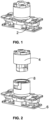
Fig. 1 is a front perspective view of the rotary plug electrical connector assembly according to the invention; -
Fig. 2 is an exploded perspective view of the connector assembly; -
Figs. 3 and 4 are exploded perspective view of the plug and socket, respectively, of the connector assembly; -
Fig. 5 is a front sectional view of the connector assembly; -
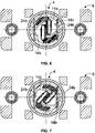
Figs. 6 and 7 are top sectional views through an upper portion of the connector assembly taken along line 6-6 ofFig. 5 showing the power contacts of the plug and socket in the operable and inoperable positions, respectively; -
Figs. 8 and 9 are top sectional view of a lower portion the connector assembly taken along line 8-8 ofFig. 5 showing the signal contacts of the plug and socket in the operable and inoperable positions, respectively; -
Fig. 10 is a perspective view of a first embodiment of the plug power contact assembly having an S-shaped cross-sectional configuration; -
Fig. 11 is a perspective view of the plug power contact assembly ofFig. 10 arranged within the socket power contacts; -
Fig. 12 is a perspective view of a second embodiment of the plug power contact assembly having a U-shaped cross-sectional configuration; -
Fig. 13 is a perspective view of the plug power contact assembly ofFig. 12 arranged within the socket power contacts; -
Fig. 14 is a perspective similar toFig. 13 but including springs arranged between the opposed pairs of contacts of the plug power contact assembly; -
Fig. 15 is a perspective view of a third embodiment of the plug power contact assembly having an extended S-shaped cross-sectional configuration; -
Fig. 16 is a perspective view of the plug power contact assembly ofFig. 15 arranged within the socket power contacts; -
Fig. 17 is a perspective view of a further embodiment of the plug power contact assembly having an S-shaped cross-sectional configuration; and -
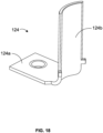
Fig. 18 is a perspective view of a socket power contact having a concave contact surface according to an alternate embodiment of the invention. - Referring first to
Figs. 1 and 2 , theelectrical connector assembly 2 according to the invention includes aplug 4 andsocket 6. The socket includes areceptacle 8 in which the plug is arranged as shown inFig. 5 . As will be developed in greater detail below, the plug is configured for rotation within the socket receptacle. - As shown in
Fig. 3 , the plug includes a generallycylindrical housing 10 which is formed of a durable rigid material such as synthetic plastic. The plug includes an inner chamber 12 (shown inFig. 5 ) within which is arranged apower contact assembly 14. Acover 16 is provided to close the bottom of the plug chamber. Arranged within the cover is asignal bridge contact 18. - The
socket 6 of the connector assembly is shown inFig. 4 . It includes acylindrical housing 20 formed of non-conductive material such as synthetic plastic which contains the receptacle. The inner diameter of the receptacle corresponds with the outer diameter of the plug housing with a limited amount of play to allow the plug to rotate within the socket receptacle. An O-ring or othercircular seal 22 is provided between the upper edge of the socket housing and the lower surface of the plug housing. A pair ofpower contacts 24 are connected with the socket housing by suitable fasteners such as a pair of bolts (not shown) which cooperate withnuts 26. The socket power contacts are formed of a durable and preferably rigid conductive material such as metal. They preferably have an L-shaped configuration with thelower portions 24a thereof being connected with the socket housing. Theupper portions 24b of the socket power contacts extend upwardly into the socket receptacle in spaced relation as shown inFig. 5 . The upper portions of the socket power contacts have opposed parallel planar surfaces which are engaged by thepower contact assembly 14 of the plug as will be developed below. The socket further includes a centralsignal contact assembly 28 arranged between the power contact. The signal contact assembly is preferably centrally arranged within the socket housing and includes a spaced pair ofcontacts 28a arranged on opposite sides of the socket axis. The socket further includesadditional seals 30 andfasteners 32 for connection with additional components or modules. - In a preferred embodiment, the plug
power contact assembly 14 has acentral portion 14a from which a plurality of opposed pairs of spacedparallel blade contacts 14b extend outwardly. The blade contacts are formed of a conductive material such as metal and preferably have a resilient spring-like nature. In one embodiment shown inFigs. 10 and 11 , the contact assembly has an S-shaped cross-sectional configuration. Such a blade assembly is also shown inFigs. 6 and 7 which illustrate the plug in its operable and inoperable positions, respectively. More particularly, the plug housing includes an internal slot or channel within which thecentral portion 14a of the plug power contact assembly is retained. As shown inFig. 6 , in the operable position of the plug, a significant portion of eachblade 14a of the plug power contact assembly engages a planar surface of the adjacent socketpower contact portion 24b. In the inoperable position of theplug 4 shown inFig. 7 , a lesser portion of eachblade 14b of the plug power contact assembly engages a planar surface of the adjacent socket power contact. In either position, the blade power contacts of the plug are arranged within and biased against the socket power contacts owing to the spring force within the blades. - Referring now to
Figs. 8 and 9 , the impact of the orientation of theplug 4 relative to thesocket 6 at the signal contact interface will be described. In the operative position of the plug shown inFig. 8 , thesignal bridge contact 18 of the plug engages the upper ends of thesocket signal contacts 28a to provide an electrical connection therebetween. More particularly, thebridge signal contact 18 has a U-shaped cross-sectional configuration. The upper ends at opposite sides of the bridge contact the upper edges of the socket signal contacts. When the plug is rotated to the inoperable position shown inFig. 9 , the plug bridge signal contact is rotated out of engagement with thesocket signal contacts 28a to electrically and mechanically disconnect the plug and socket signal contacts. When the plug is in the operable position, signals transmitted between the plug and socket enable the power contacts between the plug and socket to transmit power or electrical current through the connector assembly. Accordingly, if the connector assembly is arranged between a power source such as a battery and an electrical component or module, the connector assembly supplies power from the source to the component when the plug is rotated to the operable position. However, when the plug is rotated to its inoperable position, the plug and signal contacts are disconnected. This prevents power transfer between the plug and signal power contacts, even if they remain at least partially connected. Accordingly, in the inoperable position, the connector assembly prevents "hot" plugging of the connection between the power contacts. - Alternate configurations for the plug power contact assembly are shown in
Figs. 12-17 . InFigs. 12 and 13 , thepower contact assembly 114 has a U-shaped configuration including acentral portion 114a from which a plurality of spacedparallel blade contacts 114b extend. The oppositely extending contacts abut against the planar surfaces of the opposed socketpower contacts portions 24b as shown inFig. 13 . In all embodiments, the socket power contacts are preferably rigid while the plug power blade contacts have a resilient structure which can be deformed or compressed by rotation of the plug to the operable position and which return to a normal configuration by rotation of the plug to the inoperable position. The blade contacts slide along the planar surfaces of the socket power connectors during rotation of the plug. To assist with returning the contacts to their normal configuration, biasing springs 34 may be provided between the ends ofopposed contacts 114b as shown inFig. 14 . - In
Figs. 15 and 16 , a further configuration for the plugpower contact assembly 214 is shown. It is similar to that ofFig. 10 except that the pairs of spacedparallel blade contacts 214b have alternating contacts which extend from thecentral portion 214a at first and second distances, the second distance extending to an opposite end of the central portion. In the configuration shown inFig. 17 , the blade contacts 314b of the plug power contact assembly 314 also alternate and extend at different distances, but no blade contacts extend to an opposite end of the central portion 314a. -
Fig. 18 shows an alternate configuration for asocket power contact 124. The contact has an L-shaped configuration including a first orbase portion 124a containing an opening for receiving a fastener for connection with a socket housing and asecond contact portion 124b. Thecontact portion 124b has a concave configuration to define a curved surface for contact by the plug blade contacts. The concave configuration enables the plug blade contacts to slide along thesocket contact portion 124b during movement between the operable and inoperable positions. - It will be appreciated that the socket and rotary plug connector assembly is more durable than prior rotary plug connectors in that the socket power contacts are formed of a durable metal material which is not prone to damage through use as is the case with tulip power contacts. In addition, the blade contacts of the plug power contact assembly are also more durable than pin power contacts of the prior devices. The blade contacts of the plug are arranged within or between the socket power contacts. Thus, if damage to the blade contacts occurs, the plug may be easily removed and replaced with a new plug without having to replace the socket or the entire connector assembly.
- While the preferred forms and embodiments of the invention have been illustrated and described, it will be apparent to those of ordinary skill in the art that various changes and modifications may be made without deviating from the inventive concepts set forth above.
Claims (11)
- A rotary electrical connector assembly, comprising:(a) a socket including a receptacle containing a power contact assembly including(1) a pair of opposed power contacts; and(2) a signal contact assembly arranged between and spaced from said pair of power contacts; and(b) a plug arranged within said socket receptacle and configured for rotary movement between operable and inoperable positions relative to said socket, said plug including(1) a power contact assembly including a plurality of resilient spaced blade contacts which are configured to engage said socket power contacts; and(2) a signal bridge contact configured to engage said socket signal contact assembly when said plug is in the operable position to deliver power between said plug and socket power contacts and to disengage from said socket signal contact assembly when said plug is in the inoperable position to prevent delivery of power between plug and socket power contacts.
- A rotary electrical connector assembly as defined in claim 1, wherein said pair of opposed power contacts have one of a planar and a concave contact surface.
- A rotary electrical connector assembly as defined in claim 2, wherein said plug power contact assembly comprises a central portion and opposed pairs of spaced parallel blade contacts which extend outwardly from said central portion, each pair of spaced parallel blade contacts at least partially engaging said opposed socket power contacts when said plug is rotated between said operable and inoperable positions.
- A rotary electrical connector assembly as defined in claim 3, wherein said plug spaced parallel blade contacts comprise spring contacts.
- A rotary electrical connector assembly as defined in claim 3, wherein said plug spaced parallel blade contacts have an S-shaped cross-sectional configuration.
- A rotary electrical connector assembly as defined in claim 3, wherein said pairs of spaced parallel blade contacts have alternating blade contacts which extend from said central portion at first and second distances, respectively.
- A rotary electrical connector assembly as defined in claim 6, wherein said second distance extends to an opposite end of said central portion.
- A rotary electrical connector assembly as defined in claim 3, wherein said plug spaced parallel blade contacts have a U-shaped cross-sectional configuration.
- A rotary electrical connector assembly as defined in claim 8, and further comprising a plurality of springs arranged between opposed ends of said opposed pairs of spaced parallel blade contacts which bias said opposed pairs of spaced parallel blade contacts away from each other, respectively.
- A rotary electrical connector assembly as defined in claim 2, wherein said socket signal contact assembly includes a pair of spaced parallel contacts.
- A rotary electrical connector assembly as defined in claim 10, wherein said plug signal bridge contact is configured to engage free ends of said spaced parallel contacts of said socket signal contact assembly when the plug is in the operable position.
Applications Claiming Priority (2)
| Application Number | Priority Date | Filing Date | Title |
|---|---|---|---|
| US202117392787A | 2021-08-03 | 2021-08-03 | |
| US17/445,753 US12100918B2 (en) | 2021-08-03 | 2021-08-24 | Rotary plug connector |
Publications (2)
| Publication Number | Publication Date |
|---|---|
| EP4131669A1 true EP4131669A1 (en) | 2023-02-08 |
| EP4131669B1 EP4131669B1 (en) | 2025-07-16 |
Family
ID=80406090
Family Applications (1)
| Application Number | Title | Priority Date | Filing Date |
|---|---|---|---|
| EP22187294.8A Active EP4131669B1 (en) | 2021-08-03 | 2022-07-27 | Rotary plug connector |
Country Status (3)
| Country | Link |
|---|---|
| US (1) | US12100918B2 (en) |
| EP (1) | EP4131669B1 (en) |
| CN (2) | CN215933870U (en) |
Citations (2)
| Publication number | Priority date | Publication date | Assignee | Title |
|---|---|---|---|---|
| CN2445477Y (en) * | 2000-09-27 | 2001-08-29 | 富士康(昆山)电脑接插件有限公司 | Electric connector |
| CN104426004A (en) | 2013-08-28 | 2015-03-18 | 广濑电机株式会社 | Circuit breaker device |
Family Cites Families (3)
| Publication number | Priority date | Publication date | Assignee | Title |
|---|---|---|---|---|
| US9966702B2 (en) * | 2015-05-01 | 2018-05-08 | Commscope Technologies Llc | Coaxial cable connector interface for preventing mating with incorrect connector |
| FR3068180B1 (en) * | 2017-06-26 | 2020-12-04 | Soc Dexploitation Des Procedes Marechal | ELECTRICAL CONNECTION BASE INCLUDING A MOBILE CONNECTION ELEMENT, ADDITIONAL ELECTRICAL CONNECTION BASE, AND ASSEMBLY CONTAINING SUCH BASES |
| US11469546B2 (en) * | 2020-09-29 | 2022-10-11 | Western Technology, Inc. | Electrical connector system |
-
2021
- 2021-08-24 US US17/445,753 patent/US12100918B2/en active Active
- 2021-10-22 CN CN202122557630.7U patent/CN215933870U/en active Active
-
2022
- 2022-07-27 EP EP22187294.8A patent/EP4131669B1/en active Active
- 2022-08-02 CN CN202210919409.8A patent/CN115706345A/en active Pending
Patent Citations (3)
| Publication number | Priority date | Publication date | Assignee | Title |
|---|---|---|---|---|
| CN2445477Y (en) * | 2000-09-27 | 2001-08-29 | 富士康(昆山)电脑接插件有限公司 | Electric connector |
| CN104426004A (en) | 2013-08-28 | 2015-03-18 | 广濑电机株式会社 | Circuit breaker device |
| CN104426004B (en) * | 2013-08-28 | 2017-11-10 | 广濑电机株式会社 | Tripper |
Also Published As
| Publication number | Publication date |
|---|---|
| CN115706345A (en) | 2023-02-17 |
| US20230040853A1 (en) | 2023-02-09 |
| EP4131669B1 (en) | 2025-07-16 |
| US12100918B2 (en) | 2024-09-24 |
| CN215933870U (en) | 2022-03-01 |
Similar Documents
| Publication | Publication Date | Title |
|---|---|---|
| US9634417B2 (en) | Power connector | |
| US7815471B2 (en) | Rotatable electrical interconnection device | |
| US7481664B1 (en) | Electrical connector assembly | |
| US8430679B1 (en) | Rotatable power strip | |
| US7887353B2 (en) | Electrical disconnect with push-in connectors | |
| US2699534A (en) | Two-piece separable electrical connector | |
| US20160149363A1 (en) | Power connector | |
| US8303326B1 (en) | Cable connector assembly with locking members with spring-actuated plungers | |
| AU2016347360B2 (en) | Multipolar connector | |
| EP0076063B1 (en) | An electrical connection device | |
| US20170006733A1 (en) | Power connector | |
| US20180175564A1 (en) | Slide connector | |
| US20100029096A1 (en) | Rotatable electrical interconnection device | |
| EP4030567A1 (en) | Electrical connector with plug latching assembly | |
| US5186639A (en) | Electrical connector with plug detection switch | |
| CN101578740A (en) | single type electric contact | |
| EP0394558B1 (en) | Electrical connector having a grounding pin | |
| US5554045A (en) | Latch for IC card connector | |
| US10566738B2 (en) | Electrical connector having a locking mechanism | |
| EP4131669B1 (en) | Rotary plug connector | |
| US12537341B2 (en) | Locking electrical contact device with switch | |
| CN112038817A (en) | Electrical socket | |
| US8202112B2 (en) | Connector system and shorting member | |
| US20110256782A1 (en) | Electrical connector having movable central contact | |
| US20070128938A1 (en) | Connector assembly with bracket |
Legal Events
| Date | Code | Title | Description |
|---|---|---|---|
| PUAI | Public reference made under article 153(3) epc to a published international application that has entered the european phase |
Free format text: ORIGINAL CODE: 0009012 |
|
| STAA | Information on the status of an ep patent application or granted ep patent |
Free format text: STATUS: THE APPLICATION HAS BEEN PUBLISHED |
|
| AK | Designated contracting states |
Kind code of ref document: A1 Designated state(s): AL AT BE BG CH CY CZ DE DK EE ES FI FR GB GR HR HU IE IS IT LI LT LU LV MC MK MT NL NO PL PT RO RS SE SI SK SM TR |
|
| STAA | Information on the status of an ep patent application or granted ep patent |
Free format text: STATUS: REQUEST FOR EXAMINATION WAS MADE |
|
| 17P | Request for examination filed |
Effective date: 20230801 |
|
| RBV | Designated contracting states (corrected) |
Designated state(s): AL AT BE BG CH CY CZ DE DK EE ES FI FR GB GR HR HU IE IS IT LI LT LU LV MC MK MT NL NO PL PT RO RS SE SI SK SM TR |
|
| GRAP | Despatch of communication of intention to grant a patent |
Free format text: ORIGINAL CODE: EPIDOSNIGR1 |
|
| STAA | Information on the status of an ep patent application or granted ep patent |
Free format text: STATUS: GRANT OF PATENT IS INTENDED |
|
| INTG | Intention to grant announced |
Effective date: 20250116 |
|
| P01 | Opt-out of the competence of the unified patent court (upc) registered |
Free format text: CASE NUMBER: APP_7259/2025 Effective date: 20250212 |
|
| GRAJ | Information related to disapproval of communication of intention to grant by the applicant or resumption of examination proceedings by the epo deleted |
Free format text: ORIGINAL CODE: EPIDOSDIGR1 |
|
| STAA | Information on the status of an ep patent application or granted ep patent |
Free format text: STATUS: REQUEST FOR EXAMINATION WAS MADE |
|
| GRAS | Grant fee paid |
Free format text: ORIGINAL CODE: EPIDOSNIGR3 |
|
| STAA | Information on the status of an ep patent application or granted ep patent |
Free format text: STATUS: GRANT OF PATENT IS INTENDED |
|
| GRAP | Despatch of communication of intention to grant a patent |
Free format text: ORIGINAL CODE: EPIDOSNIGR1 |
|
| INTC | Intention to grant announced (deleted) | ||
| GRAA | (expected) grant |
Free format text: ORIGINAL CODE: 0009210 |
|
| STAA | Information on the status of an ep patent application or granted ep patent |
Free format text: STATUS: THE PATENT HAS BEEN GRANTED |
|
| INTG | Intention to grant announced |
Effective date: 20250603 |
|
| AK | Designated contracting states |
Kind code of ref document: B1 Designated state(s): AL AT BE BG CH CY CZ DE DK EE ES FI FR GB GR HR HU IE IS IT LI LT LU LV MC MK MT NL NO PL PT RO RS SE SI SK SM TR |
|
| REG | Reference to a national code |
Ref country code: GB Ref legal event code: FG4D |
|
| REG | Reference to a national code |
Ref country code: CH Ref legal event code: EP |
|
| REG | Reference to a national code |
Ref country code: DE Ref legal event code: R096 Ref document number: 602022017555 Country of ref document: DE |
|
| REG | Reference to a national code |
Ref country code: IE Ref legal event code: FG4D |
|
| PGFP | Annual fee paid to national office [announced via postgrant information from national office to epo] |
Ref country code: DE Payment date: 20250723 Year of fee payment: 4 |
|
| PGFP | Annual fee paid to national office [announced via postgrant information from national office to epo] |
Ref country code: AT Payment date: 20251020 Year of fee payment: 4 |
|
| REG | Reference to a national code |
Ref country code: NL Ref legal event code: MP Effective date: 20250716 |
|
| PG25 | Lapsed in a contracting state [announced via postgrant information from national office to epo] |
Ref country code: PT Free format text: LAPSE BECAUSE OF FAILURE TO SUBMIT A TRANSLATION OF THE DESCRIPTION OR TO PAY THE FEE WITHIN THE PRESCRIBED TIME-LIMIT Effective date: 20251117 |
|
| PG25 | Lapsed in a contracting state [announced via postgrant information from national office to epo] |
Ref country code: NL Free format text: LAPSE BECAUSE OF FAILURE TO SUBMIT A TRANSLATION OF THE DESCRIPTION OR TO PAY THE FEE WITHIN THE PRESCRIBED TIME-LIMIT Effective date: 20250716 |
|
| REG | Reference to a national code |
Ref country code: AT Ref legal event code: MK05 Ref document number: 1814973 Country of ref document: AT Kind code of ref document: T Effective date: 20250716 |
|
| PG25 | Lapsed in a contracting state [announced via postgrant information from national office to epo] |
Ref country code: IS Free format text: LAPSE BECAUSE OF FAILURE TO SUBMIT A TRANSLATION OF THE DESCRIPTION OR TO PAY THE FEE WITHIN THE PRESCRIBED TIME-LIMIT Effective date: 20251116 |
|
| PG25 | Lapsed in a contracting state [announced via postgrant information from national office to epo] |
Ref country code: NO Free format text: LAPSE BECAUSE OF FAILURE TO SUBMIT A TRANSLATION OF THE DESCRIPTION OR TO PAY THE FEE WITHIN THE PRESCRIBED TIME-LIMIT Effective date: 20251016 |
|
| REG | Reference to a national code |
Ref country code: LT Ref legal event code: MG9D |
|
| PG25 | Lapsed in a contracting state [announced via postgrant information from national office to epo] |
Ref country code: AT Free format text: LAPSE BECAUSE OF FAILURE TO SUBMIT A TRANSLATION OF THE DESCRIPTION OR TO PAY THE FEE WITHIN THE PRESCRIBED TIME-LIMIT Effective date: 20250716 |
|
| PG25 | Lapsed in a contracting state [announced via postgrant information from national office to epo] |
Ref country code: FI Free format text: LAPSE BECAUSE OF FAILURE TO SUBMIT A TRANSLATION OF THE DESCRIPTION OR TO PAY THE FEE WITHIN THE PRESCRIBED TIME-LIMIT Effective date: 20250716 |
|
| PG25 | Lapsed in a contracting state [announced via postgrant information from national office to epo] |
Ref country code: HR Free format text: LAPSE BECAUSE OF FAILURE TO SUBMIT A TRANSLATION OF THE DESCRIPTION OR TO PAY THE FEE WITHIN THE PRESCRIBED TIME-LIMIT Effective date: 20250716 |
|
| PG25 | Lapsed in a contracting state [announced via postgrant information from national office to epo] |
Ref country code: GR Free format text: LAPSE BECAUSE OF FAILURE TO SUBMIT A TRANSLATION OF THE DESCRIPTION OR TO PAY THE FEE WITHIN THE PRESCRIBED TIME-LIMIT Effective date: 20251017 |
|
| PG25 | Lapsed in a contracting state [announced via postgrant information from national office to epo] |
Ref country code: SE Free format text: LAPSE BECAUSE OF FAILURE TO SUBMIT A TRANSLATION OF THE DESCRIPTION OR TO PAY THE FEE WITHIN THE PRESCRIBED TIME-LIMIT Effective date: 20250716 |
|
| PG25 | Lapsed in a contracting state [announced via postgrant information from national office to epo] |
Ref country code: LV Free format text: LAPSE BECAUSE OF FAILURE TO SUBMIT A TRANSLATION OF THE DESCRIPTION OR TO PAY THE FEE WITHIN THE PRESCRIBED TIME-LIMIT Effective date: 20250716 |
|
| PG25 | Lapsed in a contracting state [announced via postgrant information from national office to epo] |
Ref country code: BG Free format text: LAPSE BECAUSE OF FAILURE TO SUBMIT A TRANSLATION OF THE DESCRIPTION OR TO PAY THE FEE WITHIN THE PRESCRIBED TIME-LIMIT Effective date: 20250716 Ref country code: PL Free format text: LAPSE BECAUSE OF FAILURE TO SUBMIT A TRANSLATION OF THE DESCRIPTION OR TO PAY THE FEE WITHIN THE PRESCRIBED TIME-LIMIT Effective date: 20250716 |
|
| PG25 | Lapsed in a contracting state [announced via postgrant information from national office to epo] |
Ref country code: RS Free format text: LAPSE BECAUSE OF FAILURE TO SUBMIT A TRANSLATION OF THE DESCRIPTION OR TO PAY THE FEE WITHIN THE PRESCRIBED TIME-LIMIT Effective date: 20251016 |
|
| PG25 | Lapsed in a contracting state [announced via postgrant information from national office to epo] |
Ref country code: ES Free format text: LAPSE BECAUSE OF FAILURE TO SUBMIT A TRANSLATION OF THE DESCRIPTION OR TO PAY THE FEE WITHIN THE PRESCRIBED TIME-LIMIT Effective date: 20250716 |
|
| REG | Reference to a national code |
Ref country code: CH Ref legal event code: H13 Free format text: ST27 STATUS EVENT CODE: U-0-0-H10-H13 (AS PROVIDED BY THE NATIONAL OFFICE) Effective date: 20260224 |
|
| PG25 | Lapsed in a contracting state [announced via postgrant information from national office to epo] |
Ref country code: RO Free format text: LAPSE BECAUSE OF FAILURE TO SUBMIT A TRANSLATION OF THE DESCRIPTION OR TO PAY THE FEE WITHIN THE PRESCRIBED TIME-LIMIT Effective date: 20250716 Ref country code: LU Free format text: LAPSE BECAUSE OF NON-PAYMENT OF DUE FEES Effective date: 20250727 |
|
| REG | Reference to a national code |
Ref country code: BE Ref legal event code: MM Effective date: 20250731 |
|
| PG25 | Lapsed in a contracting state [announced via postgrant information from national office to epo] |
Ref country code: SM Free format text: LAPSE BECAUSE OF FAILURE TO SUBMIT A TRANSLATION OF THE DESCRIPTION OR TO PAY THE FEE WITHIN THE PRESCRIBED TIME-LIMIT Effective date: 20250716 |
|
| PG25 | Lapsed in a contracting state [announced via postgrant information from national office to epo] |
Ref country code: DK Free format text: LAPSE BECAUSE OF FAILURE TO SUBMIT A TRANSLATION OF THE DESCRIPTION OR TO PAY THE FEE WITHIN THE PRESCRIBED TIME-LIMIT Effective date: 20250716 |
|
| PG25 | Lapsed in a contracting state [announced via postgrant information from national office to epo] |
Ref country code: BE Free format text: LAPSE BECAUSE OF NON-PAYMENT OF DUE FEES Effective date: 20250731 Ref country code: IT Free format text: LAPSE BECAUSE OF FAILURE TO SUBMIT A TRANSLATION OF THE DESCRIPTION OR TO PAY THE FEE WITHIN THE PRESCRIBED TIME-LIMIT Effective date: 20250716 |
|
| PG25 | Lapsed in a contracting state [announced via postgrant information from national office to epo] |
Ref country code: CH Free format text: LAPSE BECAUSE OF NON-PAYMENT OF DUE FEES Effective date: 20250731 Ref country code: CZ Free format text: LAPSE BECAUSE OF FAILURE TO SUBMIT A TRANSLATION OF THE DESCRIPTION OR TO PAY THE FEE WITHIN THE PRESCRIBED TIME-LIMIT Effective date: 20250716 |
|
| PG25 | Lapsed in a contracting state [announced via postgrant information from national office to epo] |
Ref country code: EE Free format text: LAPSE BECAUSE OF FAILURE TO SUBMIT A TRANSLATION OF THE DESCRIPTION OR TO PAY THE FEE WITHIN THE PRESCRIBED TIME-LIMIT Effective date: 20250716 Ref country code: SK Free format text: LAPSE BECAUSE OF FAILURE TO SUBMIT A TRANSLATION OF THE DESCRIPTION OR TO PAY THE FEE WITHIN THE PRESCRIBED TIME-LIMIT Effective date: 20250716 |