EP4131605A1 - Battery pack having structure capable of swelling control and vehicle comprising same - Google Patents
Battery pack having structure capable of swelling control and vehicle comprising same Download PDFInfo
- Publication number
- EP4131605A1 EP4131605A1 EP21892379.5A EP21892379A EP4131605A1 EP 4131605 A1 EP4131605 A1 EP 4131605A1 EP 21892379 A EP21892379 A EP 21892379A EP 4131605 A1 EP4131605 A1 EP 4131605A1
- Authority
- EP
- European Patent Office
- Prior art keywords
- pack
- tray
- cover
- battery
- elastic member
- Prior art date
- Legal status (The legal status is an assumption and is not a legal conclusion. Google has not performed a legal analysis and makes no representation as to the accuracy of the status listed.)
- Granted
Links
Images


Classifications
-
- H—ELECTRICITY
- H01—ELECTRIC ELEMENTS
- H01M—PROCESSES OR MEANS, e.g. BATTERIES, FOR THE DIRECT CONVERSION OF CHEMICAL ENERGY INTO ELECTRICAL ENERGY
- H01M10/00—Secondary cells; Manufacture thereof
- H01M10/04—Construction or manufacture in general
- H01M10/0481—Compression means other than compression means for stacks of electrodes and separators
-
- H—ELECTRICITY
- H01—ELECTRIC ELEMENTS
- H01M—PROCESSES OR MEANS, e.g. BATTERIES, FOR THE DIRECT CONVERSION OF CHEMICAL ENERGY INTO ELECTRICAL ENERGY
- H01M50/00—Constructional details or processes of manufacture of the non-active parts of electrochemical cells other than fuel cells, e.g. hybrid cells
- H01M50/20—Mountings; Secondary casings or frames; Racks, modules or packs; Suspension devices; Shock absorbers; Transport or carrying devices; Holders
- H01M50/233—Mountings; Secondary casings or frames; Racks, modules or packs; Suspension devices; Shock absorbers; Transport or carrying devices; Holders characterised by physical properties of casings or racks, e.g. dimensions
- H01M50/242—Mountings; Secondary casings or frames; Racks, modules or packs; Suspension devices; Shock absorbers; Transport or carrying devices; Holders characterised by physical properties of casings or racks, e.g. dimensions adapted for protecting batteries against vibrations, collision impact or swelling
-
- H—ELECTRICITY
- H01—ELECTRIC ELEMENTS
- H01M—PROCESSES OR MEANS, e.g. BATTERIES, FOR THE DIRECT CONVERSION OF CHEMICAL ENERGY INTO ELECTRICAL ENERGY
- H01M10/00—Secondary cells; Manufacture thereof
- H01M10/42—Methods or arrangements for servicing or maintenance of secondary cells or secondary half-cells
-
- H—ELECTRICITY
- H01—ELECTRIC ELEMENTS
- H01M—PROCESSES OR MEANS, e.g. BATTERIES, FOR THE DIRECT CONVERSION OF CHEMICAL ENERGY INTO ELECTRICAL ENERGY
- H01M50/00—Constructional details or processes of manufacture of the non-active parts of electrochemical cells other than fuel cells, e.g. hybrid cells
- H01M50/20—Mountings; Secondary casings or frames; Racks, modules or packs; Suspension devices; Shock absorbers; Transport or carrying devices; Holders
- H01M50/204—Racks, modules or packs for multiple batteries or multiple cells
- H01M50/207—Racks, modules or packs for multiple batteries or multiple cells characterised by their shape
- H01M50/209—Racks, modules or packs for multiple batteries or multiple cells characterised by their shape adapted for prismatic or rectangular cells
-
- H—ELECTRICITY
- H01—ELECTRIC ELEMENTS
- H01M—PROCESSES OR MEANS, e.g. BATTERIES, FOR THE DIRECT CONVERSION OF CHEMICAL ENERGY INTO ELECTRICAL ENERGY
- H01M50/00—Constructional details or processes of manufacture of the non-active parts of electrochemical cells other than fuel cells, e.g. hybrid cells
- H01M50/20—Mountings; Secondary casings or frames; Racks, modules or packs; Suspension devices; Shock absorbers; Transport or carrying devices; Holders
- H01M50/204—Racks, modules or packs for multiple batteries or multiple cells
- H01M50/207—Racks, modules or packs for multiple batteries or multiple cells characterised by their shape
- H01M50/211—Racks, modules or packs for multiple batteries or multiple cells characterised by their shape adapted for pouch cells
-
- H—ELECTRICITY
- H01—ELECTRIC ELEMENTS
- H01M—PROCESSES OR MEANS, e.g. BATTERIES, FOR THE DIRECT CONVERSION OF CHEMICAL ENERGY INTO ELECTRICAL ENERGY
- H01M50/00—Constructional details or processes of manufacture of the non-active parts of electrochemical cells other than fuel cells, e.g. hybrid cells
- H01M50/20—Mountings; Secondary casings or frames; Racks, modules or packs; Suspension devices; Shock absorbers; Transport or carrying devices; Holders
- H01M50/218—Mountings; Secondary casings or frames; Racks, modules or packs; Suspension devices; Shock absorbers; Transport or carrying devices; Holders characterised by the material
- H01M50/22—Mountings; Secondary casings or frames; Racks, modules or packs; Suspension devices; Shock absorbers; Transport or carrying devices; Holders characterised by the material of the casings or racks
- H01M50/222—Inorganic material
- H01M50/224—Metals
-
- H—ELECTRICITY
- H01—ELECTRIC ELEMENTS
- H01M—PROCESSES OR MEANS, e.g. BATTERIES, FOR THE DIRECT CONVERSION OF CHEMICAL ENERGY INTO ELECTRICAL ENERGY
- H01M50/00—Constructional details or processes of manufacture of the non-active parts of electrochemical cells other than fuel cells, e.g. hybrid cells
- H01M50/20—Mountings; Secondary casings or frames; Racks, modules or packs; Suspension devices; Shock absorbers; Transport or carrying devices; Holders
- H01M50/233—Mountings; Secondary casings or frames; Racks, modules or packs; Suspension devices; Shock absorbers; Transport or carrying devices; Holders characterised by physical properties of casings or racks, e.g. dimensions
- H01M50/24—Mountings; Secondary casings or frames; Racks, modules or packs; Suspension devices; Shock absorbers; Transport or carrying devices; Holders characterised by physical properties of casings or racks, e.g. dimensions adapted for protecting batteries from their environment, e.g. from corrosion
-
- H—ELECTRICITY
- H01—ELECTRIC ELEMENTS
- H01M—PROCESSES OR MEANS, e.g. BATTERIES, FOR THE DIRECT CONVERSION OF CHEMICAL ENERGY INTO ELECTRICAL ENERGY
- H01M50/00—Constructional details or processes of manufacture of the non-active parts of electrochemical cells other than fuel cells, e.g. hybrid cells
- H01M50/20—Mountings; Secondary casings or frames; Racks, modules or packs; Suspension devices; Shock absorbers; Transport or carrying devices; Holders
- H01M50/249—Mountings; Secondary casings or frames; Racks, modules or packs; Suspension devices; Shock absorbers; Transport or carrying devices; Holders specially adapted for aircraft or vehicles, e.g. cars or trains
-
- H—ELECTRICITY
- H01—ELECTRIC ELEMENTS
- H01M—PROCESSES OR MEANS, e.g. BATTERIES, FOR THE DIRECT CONVERSION OF CHEMICAL ENERGY INTO ELECTRICAL ENERGY
- H01M50/00—Constructional details or processes of manufacture of the non-active parts of electrochemical cells other than fuel cells, e.g. hybrid cells
- H01M50/20—Mountings; Secondary casings or frames; Racks, modules or packs; Suspension devices; Shock absorbers; Transport or carrying devices; Holders
- H01M50/258—Modular batteries; Casings provided with means for assembling
-
- H—ELECTRICITY
- H01—ELECTRIC ELEMENTS
- H01M—PROCESSES OR MEANS, e.g. BATTERIES, FOR THE DIRECT CONVERSION OF CHEMICAL ENERGY INTO ELECTRICAL ENERGY
- H01M50/00—Constructional details or processes of manufacture of the non-active parts of electrochemical cells other than fuel cells, e.g. hybrid cells
- H01M50/20—Mountings; Secondary casings or frames; Racks, modules or packs; Suspension devices; Shock absorbers; Transport or carrying devices; Holders
- H01M50/262—Mountings; Secondary casings or frames; Racks, modules or packs; Suspension devices; Shock absorbers; Transport or carrying devices; Holders with fastening means, e.g. locks
- H01M50/264—Mountings; Secondary casings or frames; Racks, modules or packs; Suspension devices; Shock absorbers; Transport or carrying devices; Holders with fastening means, e.g. locks for cells or batteries, e.g. straps, tie rods or peripheral frames
-
- H—ELECTRICITY
- H01—ELECTRIC ELEMENTS
- H01M—PROCESSES OR MEANS, e.g. BATTERIES, FOR THE DIRECT CONVERSION OF CHEMICAL ENERGY INTO ELECTRICAL ENERGY
- H01M50/00—Constructional details or processes of manufacture of the non-active parts of electrochemical cells other than fuel cells, e.g. hybrid cells
- H01M50/20—Mountings; Secondary casings or frames; Racks, modules or packs; Suspension devices; Shock absorbers; Transport or carrying devices; Holders
- H01M50/271—Lids or covers for the racks or secondary casings
-
- H—ELECTRICITY
- H01—ELECTRIC ELEMENTS
- H01M—PROCESSES OR MEANS, e.g. BATTERIES, FOR THE DIRECT CONVERSION OF CHEMICAL ENERGY INTO ELECTRICAL ENERGY
- H01M2220/00—Batteries for particular applications
- H01M2220/20—Batteries in motive systems, e.g. vehicle, ship, plane
-
- Y—GENERAL TAGGING OF NEW TECHNOLOGICAL DEVELOPMENTS; GENERAL TAGGING OF CROSS-SECTIONAL TECHNOLOGIES SPANNING OVER SEVERAL SECTIONS OF THE IPC; TECHNICAL SUBJECTS COVERED BY FORMER USPC CROSS-REFERENCE ART COLLECTIONS [XRACs] AND DIGESTS
- Y02—TECHNOLOGIES OR APPLICATIONS FOR MITIGATION OR ADAPTATION AGAINST CLIMATE CHANGE
- Y02E—REDUCTION OF GREENHOUSE GAS [GHG] EMISSIONS, RELATED TO ENERGY GENERATION, TRANSMISSION OR DISTRIBUTION
- Y02E60/00—Enabling technologies; Technologies with a potential or indirect contribution to GHG emissions mitigation
- Y02E60/10—Energy storage using batteries
Definitions
- the present disclosure relates to a battery pack having a structure capable of swelling control and a vehicle including the battery pack, and more particularly, to a battery pack having a structure in which the amount of swelling occurring in a stack direction of a cell stack may be minimized by minimizing a stack thickness of one cell stack and a structure in which a pressure applied to a battery cell is relatively constantly increased as the amount of swelling is increased, and a vehicle including the battery pack.
- a conventional battery pack in order to control swelling of a battery cell, has a structure in which a buffer pad is inserted between adjacent battery cells and/or into an outermost portion of a cell stack, a structure in which an empty space is secured by considering volume expansion due to swelling of a battery cell in a pack housing, or a structure in which a pack housing is deformed according to swelling of a battery cell to absorb the swelling.
- a stack direction of battery cells is usually parallel to the ground or a bottom surface of a pack housing. This structure is disadvantageous in terms of securing structural rigidity of a battery pack and securing high energy density.
- a buffer pad when a buffer pad is used to absorb swelling, as the amount of swelling is increased, the magnitude of a force required to compress the buffer pad is further increased, and thus, a pressure applied to a battery cell is explosively increased.
- the present disclosure is designed to solve the problems of the related art, and therefore the present disclosure is directed to preventing a decrease in energy density due to an empty space for absorbing volume expansion of a battery cell due to swelling, securing structural rigidity of a battery pack, and preventing an explosive increase in a pressure applied to the battery cell as the amount of swelling is increased.
- a battery pack including: a plurality of battery modules; a pack tray in which the plurality of battery modules are accommodated; a module cover covering an opening portion formed over the pack tray; a pack cover covering the module cover; and an upper elastic member located between the module cover and the pack cover and compressed, when the module cover moves toward the pack cover due to swelling of the battery module, to absorb volume expansion due to the swelling.
- the battery module may include: a module tray including a tray base and a tray partition wall extending in a direction perpendicular to the tray base and dividing a seating space on the tray base in a width direction of the tray base; a first cell stack located on the tray base and located on a side of the tray partition wall; and a second cell stack located on the tray base and located on the other side of the tray partition wall.
- the upper elastic member may include: a first upper elastic member located at a position corresponding to the first cell stack; and a second upper elastic member located at a position corresponding to the second cell stack.
- Each of the first cell stack and the second cells tack may include a plurality of battery cells stacked in a direction perpendicular to the tray base.
- the pack tray may include: a dividing beam configured to divide a receiving space of the battery module formed inside the pack tray in a width direction of the pack tray; and a cross beam configured to divide the space divided by the dividing beam in a longitudinal direction of the pack tray.
- the module cover and the pack cover may be fastened to the pack tray by bolts passing through the module cover and the pack cover, wherein a movement of the module cover according to the swelling is guided by the bolts.
- the bolts may include: a first bolt fastened to the cross beam by sequentially passing through the pack cover and the module cover; and a second bolt fastened to the tray partition wall by sequentially passing through the pack cover and the module cover.
- the pack cover may include a plurality of cover protrusions protruding from an inner surface of the pack cover, wherein the first upper elastic member and the second upper elastic member are located between a pair of adjacent cover protrusions.
- the pack cover may include a cover receiving groove formed in a top surface of the pack cover so that the first bolt and the second bolt are not exposed to the top of the pack cover, wherein the cover receiving groove is formed at a position corresponding to the cover protrusion.
- the battery pack may further include a lower elastic member located between the pack tray and the tray base and compressed, when the tray base moves toward the pack tray due to swelling of the battery module, to absorb volume expansion due to the swelling.
- the lower elastic member may include: a first lower elastic member located at a position corresponding to the first cell stack; and a second lower elastic member located at a position corresponding to the second cell stack.
- the tray base may be fastened to the tray partition wall by a third bolt passing through the pack tray and the tray base, wherein a movement of the tray base according to the swelling is guided by the third bolt.
- the pack tray may include a tray protrusion protruding from an inner surface of the pack tray, wherein the first lower elastic member and the second lower elastic member are located between the tray protrusion and the cross beam which are adjacent to each other.
- the pack tray may include a tray receiving groove formed in a bottom surface of the pack tray so that the third bolt is not exposed to the bottom of the pack tray, wherein the tray receiving groove is formed at a position corresponding to the tray protrusion.
- a vehicle including the battery pack as described above.
- a decrease in energy density due to an empty space for absorbing volume expansion of a battery cell due to swelling may be prevented, structural rigidity of a battery pack may be secured, and an explosive increase in a pressure applied to the battery cell as the amount of swelling is increased may be prevented.
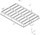
- a battery pack 1 includes a plurality of battery modules 10, a pack tray 20, a module cover 30, a pack cover 40, and an upper elastic member 50.
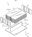
- Each of the plurality of battery modules 10 includes a module tray 100 and a cell stack 200.
- the battery module 10 may further include a pair of bus bar frame assemblies 300.
- the module tray 100 includes a tray base 110 and a tray partition wall 120.
- the tray base 110 supports the cell stack 200, and is located on an inner bottom surface of the pack tray 20.
- the tray partition wall 120 extends in a direction perpendicular to the tray base 110, and divides a seating space on the tray base 110 in a width direction (direction parallel to an X-axis) of the tray base 110.
- the cell stack 200 is located on the tray base 110.
- the cell stack 200 includes a first cell stack 200A and a second cell stack 200B.
- the first cell stack 200A is located on the tray base 110, and is located on a side of the tray partition wall 120.
- the second cell stack 200B is located on the tray base 110, and is located on the other side of the tray partition wall 120.
- Each of the first cell stack 200A and the second cell stack 200B includes a plurality of battery cells 210 stacked in a direction perpendicular to the tray base 110.
- the battery cell 210 may be a pouch-type battery cell.
- the pair of bus bar frame assemblies 300 are coupled to the first cell stack 200A and the second cell stack 200B from a side and the other side of the module tray 100 in a longitudinal direction (direction parallel to a Y-axis) of the module tray 100. That is, the pair of bus bar frame assemblies 300 are respectively coupled to a side and the other side of the first cell stack 200A and the second cell stack 200B in a longitudinal direction (direction parallel to the Y-axis) of the first cell stack 200A and the second cell stack 200B.
- the pair of bus bar frame assemblies 300 may electrically connect the plurality of battery cells 210.
- Each of the pair of bus bar frame assemblies 300 includes a bus bar frame 310 and a bus bar 320.
- the bus bar frame 310 includes a lead slit 310a through which an electrode lead 211 of the battery cell 210 may be drawn out.
- the bus bar 320 may be fixed to the bus bar frame 310, and may be coupled by welding or the like to the electrode lead 211 of each of the plurality of battery cells 210.
- the pack tray 20 accommodates a plurality of battery modules 10 in a receiving space formed inside the pack tray 20.
- the pack tray 20 includes a base plate forming the bottom and a side plate forming a side wall.
- the pack tray 20 includes a dividing beam 21 and a plurality of cross beams 22 for dividing the receiving space inside the pack tray 20 and increasing structural rigidity of the battery pack 1.
- the dividing beam 21 divides the receiving space of the battery module 10 formed inside the pack tray 20 in a width direction (direction parallel to the Y-axis) of the pack tray 20.
- the cross beam 22 divides the space divided by the dividing beam 21 in a longitudinal direction (direction parallel to the X-axis) of the pack tray 20.
- the cross beam 22 is located between adjacent battery modules 10, and is located between an inner surface of the pack tray 20 and a pair of battery modules 10 located at outermost positions from among the plurality of battery modules 10 in a longitudinal direction (direction parallel to the X-axis) of the battery pack 1. Accordingly, the cross beam 22 is located on a side and the other side of all of the battery modules 10 in a width direction (parallel to the X-axis) of all of the battery modules 10.
- the module cover 30 covers an opening portion formed over the pack tray 20, and faces the battery module 10.
- the pack cover 40 is located over the module cover 30 and covers the module cover 30.
- the upper elastic member 50 is located between the module cover 30 and the pack cover 40. As the module cover 30 moves toward the pack cover 40 due to swelling of the battery module 10, the upper elastic member 50 is compressed to absorb volume expansion due to the swelling.
- the module cover 30 may include a first module cover 30A covering the battery modules 10 located on a side of the dividing beam 21 and a second module cover 30B covering the battery modules 10 located on the other side of the dividing beam 21 in the receiving space for the battery module 10 divided by the dividing beam 21.
- the upper elastic member 50 may include a first upper elastic member 50A located at a position corresponding to the first cell stack 200A and a second upper elastic member 50B located at a position corresponding to the second cell stack 200B.
- the battery pack 1 according to an embodiment of the present disclosure may have a structure in which swelling of each battery module 10 may be individually controlled, and swelling of each of the first cell stack 200A and the second cell stack 200B may be individually controlled.
- the module cover 30 and the pack cover 40 are fastened to the pack tray 20 by bolts passing through the module cover 30 and the pack cover 40.
- a movement of the module cover 30 according to the swelling may be guided by the bolts B.
- the bolts include a first bolt B1 fastened to the cross beam 22 by sequentially passing through the pack cover 40 and the module cover 30 and a second bolt B2 fastened to the tray partition wall 120 by sequentially passing through the pack cover 40 and the module cover 30 from the top.
- the pack cover 40 may include a plurality of cover protrusions 40a protruding from an inner surface of the pack cover 40.
- the first upper elastic member 50A and the second upper elastic member 50B may be located between a pair of adjacent cover protrusions 40a, and the cover protrusions 40a may function as stoppers for preventing the first upper elastic member 50A and the second upper elastic member 50B from being separated from given positions.
- the cover protrusion 40a may longitudinally extend in a width direction (direction parallel to the Y-axis) of the pack cover 40.
- the first bolt B 1 and the second bolt B2 pass through the cover protrusion 40a.
- the pack cover 40 may include a cover receiving groove 40b formed in a top surface of the pack cover 40 so that the first bolt B1 and the second bolt B2 are not exposed to the top of the pack cover 40.
- the cover receiving groove 40b is formed at a position corresponding to the cover protrusion 40a. The first bolt B1 and the second bolt B2 pass through the cover receiving groove 40b.
- the battery pack 1 may further include a lower elastic member 60.
- the lower elastic member 60 is located between the pack tray 20 and the tray base 110. As the tray base 110 moves toward the base plate of the pack tray 20 due to swelling of the battery module 10, the lower elastic member 60 is compressed to absorb volume expansion due to the swelling.
- the lower elastic member 60 may include a first lower elastic member 60A located at a position corresponding to the first cell stack 200A and a second lower elastic member 60B located at a position corresponding to the second cell stack 200B.
- the tray base 110 is fastened to the tray partition wall by a third bolt B3 passing through the pack tray 20 and the tray base 110. A movement of the tray base 110 according to the swelling may be guided by the third bolt B3.
- the pack tray 20 may include a tray protrusion 20a protruding from an inner surface of the base plate of the pack tray 20.
- the first lower elastic member 60A and the second lower elastic member 60B are located between the tray protrusion 20a and the cross beam 22 which are adjacent to each other.
- the tray protrusion 20a and the cross beam 22 may function as stoppers for preventing the first lower elastic member 60A and the second lower elastic member 60B from being separated from given positions.
- the third bolt B3 passes through the tray protrusion 20a.
- the pack tray 20 may include a tray receiving groove 20b formed in a bottom surface of the base plate of the pack tray 20 so that the third bolt B3 is not exposed to the bottom of the base plate of the pack tray 20.
- the tray receiving groove 20b is formed at a position corresponding to the tray protrusion 20a.
- the third bolt B3 passes through the tray receiving groove 20b.
- a leaf spring or a coil spring may be used as the upper elastic member 50 and the lower elastic member 60.
- the leaf spring or the coil spring has a more constant increase in a pressure applied to a battery cell when the shape deformation of an elastic member due to swelling is increased, when compared to a conventional buffer pad applied to absorb swelling of a battery cell.
Landscapes
- Chemical & Material Sciences (AREA)
- Chemical Kinetics & Catalysis (AREA)
- Electrochemistry (AREA)
- General Chemical & Material Sciences (AREA)
- Engineering & Computer Science (AREA)
- Manufacturing & Machinery (AREA)
- Aviation & Aerospace Engineering (AREA)
- Inorganic Chemistry (AREA)
- Battery Mounting, Suspending (AREA)
Abstract
Description
- The present disclosure relates to a battery pack having a structure capable of swelling control and a vehicle including the battery pack, and more particularly, to a battery pack having a structure in which the amount of swelling occurring in a stack direction of a cell stack may be minimized by minimizing a stack thickness of one cell stack and a structure in which a pressure applied to a battery cell is relatively constantly increased as the amount of swelling is increased, and a vehicle including the battery pack.
- The present application claims priority to
Korean Patent Application No. 10-2020-0152314 filed on November 13, 2020 - In general, in order to control swelling of a battery cell, a conventional battery pack has a structure in which a buffer pad is inserted between adjacent battery cells and/or into an outermost portion of a cell stack, a structure in which an empty space is secured by considering volume expansion due to swelling of a battery cell in a pack housing, or a structure in which a pack housing is deformed according to swelling of a battery cell to absorb the swelling.
- In the conventional battery pack structure, according to the amount of swelling which is increased as the number of battery cells constituting a cell stack is increased, it is required to secure a larger empty space and/or apply a larger number of buffer pads. Also, in this conventional structure, typically, a stack direction of battery cells is usually parallel to the ground or a bottom surface of a pack housing. This structure is disadvantageous in terms of securing structural rigidity of a battery pack and securing high energy density.
- Also, when a buffer pad is used to absorb swelling, as the amount of swelling is increased, the magnitude of a force required to compress the buffer pad is further increased, and thus, a pressure applied to a battery cell is explosively increased.
- The present disclosure is designed to solve the problems of the related art, and therefore the present disclosure is directed to preventing a decrease in energy density due to an empty space for absorbing volume expansion of a battery cell due to swelling, securing structural rigidity of a battery pack, and preventing an explosive increase in a pressure applied to the battery cell as the amount of swelling is increased.
- However, the technical purpose to be solved by the present disclosure is not limited to the above, and other objects not mentioned herein will be clearly understood by one of ordinary skill in the art from the following disclosure.
- In one aspect of the present disclosure, there is provided a battery pack including: a plurality of battery modules; a pack tray in which the plurality of battery modules are accommodated; a module cover covering an opening portion formed over the pack tray; a pack cover covering the module cover; and an upper elastic member located between the module cover and the pack cover and compressed, when the module cover moves toward the pack cover due to swelling of the battery module, to absorb volume expansion due to the swelling.
- The battery module may include: a module tray including a tray base and a tray partition wall extending in a direction perpendicular to the tray base and dividing a seating space on the tray base in a width direction of the tray base; a first cell stack located on the tray base and located on a side of the tray partition wall; and a second cell stack located on the tray base and located on the other side of the tray partition wall.
- The upper elastic member may include: a first upper elastic member located at a position corresponding to the first cell stack; and a second upper elastic member located at a position corresponding to the second cell stack.
- Each of the first cell stack and the second cells tack may include a plurality of battery cells stacked in a direction perpendicular to the tray base.
- The pack tray may include: a dividing beam configured to divide a receiving space of the battery module formed inside the pack tray in a width direction of the pack tray; and a cross beam configured to divide the space divided by the dividing beam in a longitudinal direction of the pack tray.
- The module cover and the pack cover may be fastened to the pack tray by bolts passing through the module cover and the pack cover, wherein a movement of the module cover according to the swelling is guided by the bolts.
- The bolts may include: a first bolt fastened to the cross beam by sequentially passing through the pack cover and the module cover; and a second bolt fastened to the tray partition wall by sequentially passing through the pack cover and the module cover.
- The pack cover may include a plurality of cover protrusions protruding from an inner surface of the pack cover, wherein the first upper elastic member and the second upper elastic member are located between a pair of adjacent cover protrusions.
- The pack cover may include a cover receiving groove formed in a top surface of the pack cover so that the first bolt and the second bolt are not exposed to the top of the pack cover, wherein the cover receiving groove is formed at a position corresponding to the cover protrusion.
- The battery pack may further include a lower elastic member located between the pack tray and the tray base and compressed, when the tray base moves toward the pack tray due to swelling of the battery module, to absorb volume expansion due to the swelling.
- The lower elastic member may include: a first lower elastic member located at a position corresponding to the first cell stack; and a second lower elastic member located at a position corresponding to the second cell stack.
- The tray base may be fastened to the tray partition wall by a third bolt passing through the pack tray and the tray base, wherein a movement of the tray base according to the swelling is guided by the third bolt.
- The pack tray may include a tray protrusion protruding from an inner surface of the pack tray, wherein the first lower elastic member and the second lower elastic member are located between the tray protrusion and the cross beam which are adjacent to each other.
- The pack tray may include a tray receiving groove formed in a bottom surface of the pack tray so that the third bolt is not exposed to the bottom of the pack tray, wherein the tray receiving groove is formed at a position corresponding to the tray protrusion.
- In another aspect of the present disclosure, there is also provided a vehicle including the battery pack as described above.
- According to an aspect of the present disclosure, a decrease in energy density due to an empty space for absorbing volume expansion of a battery cell due to swelling may be prevented, structural rigidity of a battery pack may be secured, and an explosive increase in a pressure applied to the battery cell as the amount of swelling is increased may be prevented.
- The accompanying drawings illustrate a preferred embodiment of the present disclosure and together with the foregoing disclosure, serve to provide further understanding of the technical features of the present disclosure, and thus, the present disclosure is not construed as being limited to the drawing.
-
FIG. 1 is a view illustrating a battery pack according to an embodiment of the present disclosure. -
FIG. 2 is an exploded perspective view illustrating the battery pack ofFIG. 1 . -
FIG. 3 is a partial enlarged view ofFIG. 2 . -
FIG. 4 is a view illustrating a battery module of the present disclosure. -
FIGS. 5 and6 are partial cross-sectional views illustrating a battery pack, taken along line A-A', according to an embodiment of the present disclosure. - Hereinafter, preferred embodiments of the present disclosure will be described in detail with reference to the accompanying drawings. Prior to the description, it should be understood that the terms used in the specification and the appended claims should not be construed as limited to general and dictionary meanings, but interpreted based on the meanings and concepts corresponding to technical aspects of the present disclosure on the basis of the principle that the inventor is allowed to define terms appropriately for the best explanation. Therefore, the description proposed herein is just a preferable example for the purpose of illustrations only, not intended to limit the scope of the disclosure, so it should be understood that other equivalents and modifications could be made thereto without departing from the scope of the disclosure.
- Referring to
FIGS. 1 through 5 , a battery pack 1 includes a plurality ofbattery modules 10, apack tray 20, amodule cover 30, apack cover 40, and an upperelastic member 50. - Each of the plurality of
battery modules 10 includes amodule tray 100 and acell stack 200. Thebattery module 10 may further include a pair of busbar frame assemblies 300. - The
module tray 100 includes atray base 110 and atray partition wall 120. Thetray base 110 supports thecell stack 200, and is located on an inner bottom surface of thepack tray 20. Thetray partition wall 120 extends in a direction perpendicular to thetray base 110, and divides a seating space on thetray base 110 in a width direction (direction parallel to an X-axis) of thetray base 110. - The
cell stack 200 is located on thetray base 110. Thecell stack 200 includes afirst cell stack 200A and asecond cell stack 200B. Thefirst cell stack 200A is located on thetray base 110, and is located on a side of thetray partition wall 120. Thesecond cell stack 200B is located on thetray base 110, and is located on the other side of thetray partition wall 120. - Each of the
first cell stack 200A and thesecond cell stack 200B includes a plurality ofbattery cells 210 stacked in a direction perpendicular to thetray base 110. Thebattery cell 210 may be a pouch-type battery cell. - The pair of bus
bar frame assemblies 300 are coupled to thefirst cell stack 200A and thesecond cell stack 200B from a side and the other side of themodule tray 100 in a longitudinal direction (direction parallel to a Y-axis) of themodule tray 100. That is, the pair of busbar frame assemblies 300 are respectively coupled to a side and the other side of thefirst cell stack 200A and thesecond cell stack 200B in a longitudinal direction (direction parallel to the Y-axis) of thefirst cell stack 200A and thesecond cell stack 200B. The pair of busbar frame assemblies 300 may electrically connect the plurality ofbattery cells 210. - Each of the pair of bus
bar frame assemblies 300 includes abus bar frame 310 and abus bar 320. Thebus bar frame 310 includes alead slit 310a through which anelectrode lead 211 of thebattery cell 210 may be drawn out. Thebus bar 320 may be fixed to thebus bar frame 310, and may be coupled by welding or the like to theelectrode lead 211 of each of the plurality ofbattery cells 210. - The pack tray 20 accommodates a plurality of
battery modules 10 in a receiving space formed inside thepack tray 20. Thepack tray 20 includes a base plate forming the bottom and a side plate forming a side wall. Thepack tray 20 includes a dividingbeam 21 and a plurality ofcross beams 22 for dividing the receiving space inside thepack tray 20 and increasing structural rigidity of the battery pack 1. - The dividing
beam 21 divides the receiving space of thebattery module 10 formed inside thepack tray 20 in a width direction (direction parallel to the Y-axis) of thepack tray 20. Thecross beam 22 divides the space divided by the dividingbeam 21 in a longitudinal direction (direction parallel to the X-axis) of thepack tray 20. Thecross beam 22 is located betweenadjacent battery modules 10, and is located between an inner surface of thepack tray 20 and a pair ofbattery modules 10 located at outermost positions from among the plurality ofbattery modules 10 in a longitudinal direction (direction parallel to the X-axis) of the battery pack 1. Accordingly, thecross beam 22 is located on a side and the other side of all of thebattery modules 10 in a width direction (parallel to the X-axis) of all of thebattery modules 10. - The module cover 30 covers an opening portion formed over the
pack tray 20, and faces thebattery module 10. Thepack cover 40 is located over themodule cover 30 and covers themodule cover 30. The upperelastic member 50 is located between themodule cover 30 and thepack cover 40. As themodule cover 30 moves toward thepack cover 40 due to swelling of thebattery module 10, the upperelastic member 50 is compressed to absorb volume expansion due to the swelling. Themodule cover 30 may include afirst module cover 30A covering thebattery modules 10 located on a side of thedividing beam 21 and a second module cover 30B covering thebattery modules 10 located on the other side of thedividing beam 21 in the receiving space for thebattery module 10 divided by thedividing beam 21. When a plurality of module covers 30A, 30B are provided, because swelling of each of thebattery modules 10 accommodated in different spaces may be individually controlled, a uniform pressure may be applied to the plurality ofbattery modules 10. - The upper
elastic member 50 may include a first upperelastic member 50A located at a position corresponding to thefirst cell stack 200A and a second upperelastic member 50B located at a position corresponding to thesecond cell stack 200B. As such, the battery pack 1 according to an embodiment of the present disclosure may have a structure in which swelling of eachbattery module 10 may be individually controlled, and swelling of each of thefirst cell stack 200A and thesecond cell stack 200B may be individually controlled. - The
module cover 30 and thepack cover 40 are fastened to thepack tray 20 by bolts passing through themodule cover 30 and thepack cover 40. A movement of themodule cover 30 according to the swelling may be guided by the bolts B. The bolts include a first bolt B1 fastened to thecross beam 22 by sequentially passing through thepack cover 40 and themodule cover 30 and a second bolt B2 fastened to thetray partition wall 120 by sequentially passing through thepack cover 40 and the module cover 30 from the top. - The
pack cover 40 may include a plurality ofcover protrusions 40a protruding from an inner surface of thepack cover 40. In this case, the first upperelastic member 50A and the second upperelastic member 50B may be located between a pair ofadjacent cover protrusions 40a, and thecover protrusions 40a may function as stoppers for preventing the first upperelastic member 50A and the second upperelastic member 50B from being separated from given positions. Thecover protrusion 40a may longitudinally extend in a width direction (direction parallel to the Y-axis) of thepack cover 40. The first bolt B 1 and the second bolt B2 pass through thecover protrusion 40a. - The
pack cover 40 may include acover receiving groove 40b formed in a top surface of thepack cover 40 so that the first bolt B1 and the second bolt B2 are not exposed to the top of thepack cover 40. Thecover receiving groove 40b is formed at a position corresponding to thecover protrusion 40a. The first bolt B1 and the second bolt B2 pass through thecover receiving groove 40b. - Referring to
FIG. 6 together withFIGS. 1 through 4 , the battery pack 1 may further include a lowerelastic member 60. The lowerelastic member 60 is located between thepack tray 20 and thetray base 110. As thetray base 110 moves toward the base plate of thepack tray 20 due to swelling of thebattery module 10, the lowerelastic member 60 is compressed to absorb volume expansion due to the swelling. - The lower
elastic member 60 may include a first lowerelastic member 60A located at a position corresponding to thefirst cell stack 200A and a second lowerelastic member 60B located at a position corresponding to thesecond cell stack 200B. - The
tray base 110 is fastened to the tray partition wall by a third bolt B3 passing through thepack tray 20 and thetray base 110. A movement of thetray base 110 according to the swelling may be guided by the third bolt B3. - The
pack tray 20 may include atray protrusion 20a protruding from an inner surface of the base plate of thepack tray 20. In this case, the first lowerelastic member 60A and the second lowerelastic member 60B are located between thetray protrusion 20a and thecross beam 22 which are adjacent to each other. Thetray protrusion 20a and thecross beam 22 may function as stoppers for preventing the first lowerelastic member 60A and the second lowerelastic member 60B from being separated from given positions. The third bolt B3 passes through thetray protrusion 20a. - The
pack tray 20 may include atray receiving groove 20b formed in a bottom surface of the base plate of thepack tray 20 so that the third bolt B3 is not exposed to the bottom of the base plate of thepack tray 20. Thetray receiving groove 20b is formed at a position corresponding to thetray protrusion 20a. The third bolt B3 passes through thetray receiving groove 20b. - For example, a leaf spring or a coil spring may be used as the upper
elastic member 50 and the lowerelastic member 60. The leaf spring or the coil spring has a more constant increase in a pressure applied to a battery cell when the shape deformation of an elastic member due to swelling is increased, when compared to a conventional buffer pad applied to absorb swelling of a battery cell. - Although the embodiments of the present disclosure have been illustrated and described above, the present disclosure is not limited to the above-described specific embodiments. Various modified embodiments may be made by one of ordinary skill in the art without departing from the scope of the present disclosure as claimed in the claims.
Claims (15)
- A battery pack comprising:a plurality of battery modules;a pack tray in which the plurality of battery modules are accommodated;a module cover covering an opening portion formed over the pack tray;a pack cover covering the module cover; andan upper elastic member located between the module cover and the pack cover and compressed, when the module cover moves toward the pack cover due to swelling of the battery module, to absorb volume expansion due to the swelling.
- The battery pack of claim 1, wherein the battery module comprises:a module tray comprising a tray base and a tray partition wall extending in a direction perpendicular to the tray base and dividing a seating space on the tray base in a width direction of the tray base;a first cell stack located on the tray base and located on a side of the tray partition wall; anda second cell stack located on the tray base and located on the other side of the tray partition wall.
- The battery pack of claim 2, wherein the upper elastic member comprises:a first upper elastic member located at a position corresponding to the first cell stack; anda second upper elastic member located at a position corresponding to the second cell stack.
- The battery pack of claim 2, wherein each of the first cell stack and the second cells tack comprises a plurality of battery cells stacked in a direction perpendicular to the tray base.
- The battery pack of claim 3, wherein the pack tray comprises:a dividing beam configured to divide a receiving space of the battery module formed inside the pack tray in a width direction of the pack tray; anda cross beam configured to divide the space divided by the dividing beam in a longitudinal direction of the pack tray.
- The battery pack of claim 5, wherein the module cover and the pack cover are fastened to the pack tray by bolts passing through the module cover and the pack cover,
wherein a movement of the module cover according to the swelling is guided by the bolts. - The battery pack of claim 6, wherein the bolts comprise:a first bolt fastened to the cross beam by sequentially passing through the pack cover and the module cover; anda second bolt fastened to the tray partition wall by sequentially passing through the pack cover and the module cover.
- The battery pack of claim 7, wherein the pack cover comprises a plurality of cover protrusions protruding from an inner surface of the pack cover,
wherein the first upper elastic member and the second upper elastic member are located between a pair of adjacent cover protrusions. - The battery pack of claim 8, wherein the pack cover comprises a cover receiving groove formed in a top surface of the pack cover so that the first bolt and the second bolt are not exposed to the top of the pack cover,
wherein the cover receiving groove is formed at a position corresponding to the cover protrusion. - The battery pack of claim 5, further comprising a lower elastic member located between the pack tray and the tray base and compressed, when the tray base moves toward the pack tray due to swelling of the battery module, to absorb volume expansion due to the swelling.
- The battery pack of claim 10, wherein the lower elastic member comprises:a first lower elastic member located at a position corresponding to the first cell stack; anda second lower elastic member located at a position corresponding to the second cell stack.
- The battery pack of claim 11, wherein the tray base is fastened to the tray partition wall by a third bolt passing through the pack tray and the tray base,
wherein a movement of the tray base according to the swelling is guided by the third bolt. - The battery pack of claim 12, wherein the pack tray comprises a tray protrusion protruding from an inner surface of the pack tray,
wherein the first lower elastic member and the second lower elastic member are located between the tray protrusion and the cross beam which are adjacent to each other. - The battery pack of claim 13, wherein the pack tray comprises a tray receiving groove formed in a bottom surface of the pack tray so that the third bolt is not exposed to the bottom of the pack tray,
wherein the tray receiving groove is formed at a position corresponding to the tray protrusion. - A vehicle comprising the battery pack according to any one of claims 1 through 14.
Priority Applications (1)
| Application Number | Priority Date | Filing Date | Title |
|---|---|---|---|
| EP25199785.4A EP4632896A3 (en) | 2020-11-13 | 2021-11-12 | Battery pack having structure capable of swelling control and vehicle including the battery pack |
Applications Claiming Priority (2)
| Application Number | Priority Date | Filing Date | Title |
|---|---|---|---|
| KR1020200152314A KR20220065601A (en) | 2020-11-13 | 2020-11-13 | Battery pack having a structure capable of swelling control and Vehicle including the same |
| PCT/KR2021/016580 WO2022103212A1 (en) | 2020-11-13 | 2021-11-12 | Battery pack having structure capable of swelling control and vehicle comprising same |
Related Child Applications (2)
| Application Number | Title | Priority Date | Filing Date |
|---|---|---|---|
| EP25199785.4A Division EP4632896A3 (en) | 2020-11-13 | 2021-11-12 | Battery pack having structure capable of swelling control and vehicle including the battery pack |
| EP25199785.4A Division-Into EP4632896A3 (en) | 2020-11-13 | 2021-11-12 | Battery pack having structure capable of swelling control and vehicle including the battery pack |
Publications (3)
| Publication Number | Publication Date |
|---|---|
| EP4131605A1 true EP4131605A1 (en) | 2023-02-08 |
| EP4131605A4 EP4131605A4 (en) | 2024-06-26 |
| EP4131605B1 EP4131605B1 (en) | 2025-12-31 |
Family
ID=81601602
Family Applications (2)
| Application Number | Title | Priority Date | Filing Date |
|---|---|---|---|
| EP21892379.5A Active EP4131605B1 (en) | 2020-11-13 | 2021-11-12 | Battery pack with threshold structure and vehicle with this battery pack |
| EP25199785.4A Pending EP4632896A3 (en) | 2020-11-13 | 2021-11-12 | Battery pack having structure capable of swelling control and vehicle including the battery pack |
Family Applications After (1)
| Application Number | Title | Priority Date | Filing Date |
|---|---|---|---|
| EP25199785.4A Pending EP4632896A3 (en) | 2020-11-13 | 2021-11-12 | Battery pack having structure capable of swelling control and vehicle including the battery pack |
Country Status (7)
| Country | Link |
|---|---|
| US (3) | US20230378584A1 (en) |
| EP (2) | EP4131605B1 (en) |
| JP (1) | JP7684314B2 (en) |
| KR (1) | KR20220065601A (en) |
| CN (1) | CN115004465A (en) |
| ES (1) | ES3059523T3 (en) |
| WO (1) | WO2022103212A1 (en) |
Cited By (3)
| Publication number | Priority date | Publication date | Assignee | Title |
|---|---|---|---|---|
| EP4354596A1 (en) * | 2022-10-13 | 2024-04-17 | SK On Co., Ltd. | Battery module |
| FR3149241A1 (en) * | 2023-06-01 | 2024-12-06 | Psa Automobiles Sa | MOTOR VEHICLE COMPRISING A BATTERY BOX EQUIPPED WITH CROSSBEAMS OF OPTIMIZED WIDTH, BATTERY BOX AND METHOD BASED ON SUCH A VEHICLE |
| EP4586386A4 (en) * | 2023-08-30 | 2026-02-25 | Lg Energy Solution Ltd | PACKAGING BOX |
Families Citing this family (16)
| Publication number | Priority date | Publication date | Assignee | Title |
|---|---|---|---|---|
| KR102836822B1 (en) * | 2021-07-15 | 2025-07-21 | 컨템포러리 엠퍼렉스 테크놀로지 (홍콩) 리미티드 | Batteries and electrical devices |
| WO2024005393A1 (en) * | 2022-06-27 | 2024-01-04 | 주식회사 엘지에너지솔루션 | Battery pack |
| FR3138738A1 (en) | 2022-08-02 | 2024-02-09 | Psa Automobiles Sa | ELECTRIC STORAGE MODULE EQUIPPED WITH A DEVICE FOR MAINTAINING COMPRESSION OF THE STORAGE CELLS AND ELECTRIC ENERGY STORER INCORPORATING IT |
| KR20240039326A (en) * | 2022-09-19 | 2024-03-26 | 주식회사 엘지에너지솔루션 | Battery pack having variable coupling part for preventing structure collapse |
| CN220106707U (en) * | 2022-10-13 | 2023-11-28 | Sk新能源株式会社 | Battery module comprising a plurality of sub-modules |
| JP2025527906A (en) * | 2022-12-02 | 2025-08-22 | エルジー エナジー ソリューション リミテッド | Battery pack |
| EP4629359A4 (en) * | 2022-12-22 | 2025-12-31 | Lg Energy Solution Ltd | BATTERY PACK AND ENERGY STORAGE DEVICE SO THAT |
| KR20250030816A (en) * | 2023-08-25 | 2025-03-05 | 주식회사 엘지에너지솔루션 | Battery pack and Vehicle including the same |
| KR102754965B1 (en) * | 2023-11-02 | 2025-01-22 | 덕양산업 주식회사 | Battery pack with blocked airtight structure and enhanced rigidity |
| KR20250131536A (en) * | 2024-02-27 | 2025-09-03 | 주식회사 엘지에너지솔루션 | Battery pack and vehicle including the same |
| KR20250144783A (en) * | 2024-03-27 | 2025-10-13 | 주식회사 엘지에너지솔루션 | Battery pack and Vehicle including the same |
| KR20250146783A (en) * | 2024-04-02 | 2025-10-13 | 주식회사 엘지에너지솔루션 | Module cover, battery pack and vehicle |
| KR20250148210A (en) * | 2024-04-05 | 2025-10-14 | 주식회사 엘지에너지솔루션 | Battery pack and vehicle including the same |
| KR20250149066A (en) * | 2024-04-08 | 2025-10-15 | 주식회사 엘지에너지솔루션 | Battery pack and vehicle including the same |
| JP2026055606A (en) * | 2024-09-18 | 2026-03-31 | 株式会社デンソー | Battery pack |
| WO2026084255A1 (en) * | 2024-10-18 | 2026-04-23 | 주식회사 엘지에너지솔루션 | Pack housing and battery pack comprising same |
Family Cites Families (46)
| Publication number | Priority date | Publication date | Assignee | Title |
|---|---|---|---|---|
| JP2004055346A (en) * | 2002-07-19 | 2004-02-19 | Nissan Motor Co Ltd | Battery pack, composite battery pack, and vehicle equipped with the same |
| JP2009170140A (en) * | 2008-01-11 | 2009-07-30 | Aiko Kk | Battery module pressurizing spacer |
| JP5343048B2 (en) * | 2010-07-29 | 2013-11-13 | 日立ビークルエナジー株式会社 | Power storage module and power storage device |
| JP5625834B2 (en) * | 2010-12-02 | 2014-11-19 | 日産自動車株式会社 | Assembled battery |
| US20140220391A1 (en) * | 2011-08-26 | 2014-08-07 | Sanyo Electric Co., Ltd., | Power source apparatus, and vehicle and power storage device equipped with that power source apparatus |
| KR101319523B1 (en) * | 2011-12-19 | 2013-11-06 | 지에스나노텍 주식회사 | Thin film cells module and thin film cells package and apparatus for packaging thin film cells and method for manufacturing thin film cells package |
| DE102014116181B4 (en) * | 2014-11-06 | 2020-08-27 | Lisa Dräxlmaier GmbH | Energy storage device |
| DE102014118402A1 (en) * | 2014-12-11 | 2016-06-16 | Dr. Ing. H.C. F. Porsche Aktiengesellschaft | Cooling device and energy storage |
| KR20160091124A (en) * | 2015-01-23 | 2016-08-02 | 삼성에스디아이 주식회사 | A battery module |
| KR102094445B1 (en) | 2015-07-27 | 2020-03-27 | 주식회사 엘지화학 | Battery module, battery pack comprising the battery module and vehicle comprising the battery pack |
| JP6536679B2 (en) * | 2015-09-03 | 2019-07-03 | 株式会社村田製作所 | battery |
| EP3367460B1 (en) * | 2015-10-22 | 2021-05-05 | Envision AESC Japan Ltd. | Method for assembling a battery pack, and battery back |
| CN105404679B (en) | 2015-11-24 | 2019-02-01 | 华为技术有限公司 | Data processing method and device |
| EP3373358B1 (en) * | 2015-12-18 | 2021-02-03 | LG Chem, Ltd. | Battery pack |
| JP6520808B2 (en) * | 2016-04-21 | 2019-05-29 | トヨタ自動車株式会社 | Vehicle battery mounting structure |
| KR102061745B1 (en) | 2016-04-25 | 2020-01-02 | 주식회사 엘지화학 | Battery pack and vehicle comprising the battery pack |
| KR102018301B1 (en) | 2016-09-01 | 2019-09-04 | 주식회사 엘지화학 | Battery module and method for fabricating the same |
| KR102102927B1 (en) * | 2016-10-06 | 2020-04-21 | 주식회사 엘지화학 | Battery module, battery pack comprising the battery module and vehicle comprising the battery pack |
| JP6861045B2 (en) * | 2017-02-09 | 2021-04-21 | 株式会社エンビジョンAescジャパン | Assembled battery, battery pack, manufacturing method of assembled battery and manufacturing method of battery pack |
| KR101916429B1 (en) * | 2017-03-30 | 2018-11-07 | 엘지전자 주식회사 | Battery pack for vehicle and vehicle |
| KR102172517B1 (en) | 2017-04-04 | 2020-10-30 | 주식회사 엘지화학 | Battery Pack having crash beam structure |
| KR102065099B1 (en) * | 2017-04-04 | 2020-01-10 | 주식회사 엘지화학 | Battery Pack having crash beam and drain structure |
| KR102317506B1 (en) * | 2017-04-10 | 2021-10-26 | 삼성에스디아이 주식회사 | Battery pack |
| KR102088477B1 (en) | 2017-05-16 | 2020-03-12 | 주식회사 엘지화학 | Battery module |
| JP7049780B2 (en) * | 2017-07-11 | 2022-04-07 | 日産自動車株式会社 | battery |
| JP6960787B2 (en) * | 2017-07-11 | 2021-11-05 | 日産自動車株式会社 | battery |
| DE102017126949B4 (en) * | 2017-11-16 | 2025-02-27 | Dr. Ing. H.C. F. Porsche Aktiengesellschaft | Battery device for an at least partially electrically operated motor vehicle |
| KR102270234B1 (en) * | 2017-12-12 | 2021-06-25 | 주식회사 엘지에너지솔루션 | Battery module embedding cross beam and Battery pack comprising the battery module |
| KR102241965B1 (en) | 2017-12-26 | 2021-04-16 | 주식회사 엘지화학 | Battery pack and method of manufacturing the same |
| JP7198422B2 (en) * | 2018-01-16 | 2023-01-04 | スズキ株式会社 | Body structure of electric vehicle |
| KR102488450B1 (en) * | 2018-03-20 | 2023-01-12 | 주식회사 엘지에너지솔루션 | Pouch type secondary battery to which a swelling prevention structure is applied and battery module including the same |
| KR102640327B1 (en) * | 2018-10-19 | 2024-02-22 | 삼성에스디아이 주식회사 | Large module of battery |
| CN109713175A (en) * | 2018-11-23 | 2019-05-03 | 合肥鸿叶紫新能源有限公司 | A kind of new energy battery modules with long service life |
| CN110190212B (en) * | 2018-12-29 | 2020-02-04 | 比亚迪股份有限公司 | Power battery pack and vehicle |
| KR102392788B1 (en) * | 2019-01-08 | 2022-04-28 | 주식회사 엘지에너지솔루션 | A battery module having a foldable side plate, and Method for manufacturing the same |
| KR102298105B1 (en) * | 2019-01-08 | 2021-09-03 | 주식회사 엘지에너지솔루션 | Battery module with swelling gauge and battery pack including the same |
| KR102716908B1 (en) * | 2019-03-21 | 2024-10-11 | 주식회사 엘지에너지솔루션 | A battery module having a module housing of a thin plate type and a battery pack including the same |
| JP7157014B2 (en) * | 2019-07-10 | 2022-10-19 | 本田技研工業株式会社 | Storage modules and storage module packs |
| CN110518163B (en) | 2019-08-13 | 2022-07-19 | 孚能科技(赣州)股份有限公司 | Battery module |
| CN211252182U (en) * | 2019-09-24 | 2020-08-14 | 威马智慧出行科技(上海)有限公司 | Vehicle battery box and vehicle |
| KR102846582B1 (en) * | 2019-09-30 | 2025-08-13 | 에스케이온 주식회사 | Battery Module |
| US20210135175A1 (en) * | 2019-11-01 | 2021-05-06 | Sk Innovation Co., Ltd. | Cell-seating unit and battery module comprising the same |
| CN211907500U (en) * | 2019-12-31 | 2020-11-10 | 常熟市万隆电源技术研发有限公司 | An underground box for solar battery |
| WO2021196114A1 (en) * | 2020-04-02 | 2021-10-07 | 宁德时代新能源科技股份有限公司 | Battery module assembly, battery pack, and device using battery as power source |
| CN111769221A (en) | 2020-06-02 | 2020-10-13 | 北京新能源汽车股份有限公司蓝谷动力系统分公司 | Battery module for vehicle and vehicle |
| KR102922440B1 (en) * | 2020-09-22 | 2026-02-05 | 주식회사 엘지에너지솔루션 | Battery Pack With Improved Battery Cell Lifetime And Device Including It |
-
2020
- 2020-11-13 KR KR1020200152314A patent/KR20220065601A/en active Pending
-
2021
- 2021-11-12 US US18/031,407 patent/US20230378584A1/en active Pending
- 2021-11-12 JP JP2022545426A patent/JP7684314B2/en active Active
- 2021-11-12 CN CN202180011086.6A patent/CN115004465A/en active Pending
- 2021-11-12 EP EP21892379.5A patent/EP4131605B1/en active Active
- 2021-11-12 EP EP25199785.4A patent/EP4632896A3/en active Pending
- 2021-11-12 ES ES21892379T patent/ES3059523T3/en active Active
- 2021-11-12 WO PCT/KR2021/016580 patent/WO2022103212A1/en not_active Ceased
-
2024
- 2024-01-02 US US18/402,467 patent/US12431572B2/en active Active
-
2025
- 2025-08-29 US US19/314,249 patent/US20260005367A1/en active Pending
Cited By (3)
| Publication number | Priority date | Publication date | Assignee | Title |
|---|---|---|---|---|
| EP4354596A1 (en) * | 2022-10-13 | 2024-04-17 | SK On Co., Ltd. | Battery module |
| FR3149241A1 (en) * | 2023-06-01 | 2024-12-06 | Psa Automobiles Sa | MOTOR VEHICLE COMPRISING A BATTERY BOX EQUIPPED WITH CROSSBEAMS OF OPTIMIZED WIDTH, BATTERY BOX AND METHOD BASED ON SUCH A VEHICLE |
| EP4586386A4 (en) * | 2023-08-30 | 2026-02-25 | Lg Energy Solution Ltd | PACKAGING BOX |
Also Published As
| Publication number | Publication date |
|---|---|
| US20240136630A1 (en) | 2024-04-25 |
| CN115004465A (en) | 2022-09-02 |
| EP4131605A4 (en) | 2024-06-26 |
| EP4632896A3 (en) | 2026-01-21 |
| US20260005367A1 (en) | 2026-01-01 |
| KR20220065601A (en) | 2022-05-20 |
| US12431572B2 (en) | 2025-09-30 |
| US20230378584A1 (en) | 2023-11-23 |
| JP7684314B2 (en) | 2025-05-27 |
| JP2023511609A (en) | 2023-03-20 |
| ES3059523T3 (en) | 2026-03-20 |
| EP4131605B1 (en) | 2025-12-31 |
| WO2022103212A1 (en) | 2022-05-19 |
| EP4632896A2 (en) | 2025-10-15 |
Similar Documents
| Publication | Publication Date | Title |
|---|---|---|
| EP4131605A1 (en) | Battery pack having structure capable of swelling control and vehicle comprising same | |
| EP4142029B1 (en) | Battery module having structure capable of absorbing cell swelling, and battery pack and vehicle comprising same | |
| KR102065105B1 (en) | Drawer type battery pack | |
| EP3309866A1 (en) | Battery module, battery pack comprising same, and automobile | |
| JP7133702B2 (en) | Fixing structure of end plate and battery device | |
| CN113363647B (en) | Battery device and motor vehicle with battery device | |
| EP4407770B1 (en) | Battery pack | |
| JP6798310B2 (en) | Battery pack for vehicle mounting | |
| US20250158206A1 (en) | Cell stack assembly, and battery pack comprising the cell stack assembly | |
| EP1901366A1 (en) | Electric storage battery | |
| US20250158205A1 (en) | Battery module and battery pack | |
| EP4181294B1 (en) | Battery module having structure enabling uniform pressure to be applied during swelling, and battery pack and vehicle comprising same | |
| JP7202205B2 (en) | Restraining member | |
| EP4510339A1 (en) | Cell stack assembly and battery pack comprising cell stack assembly | |
| KR20210111104A (en) | Battery module having brackets that can adjust the width, and a battery pack comprising the same, and a vehicle including such a battery pack | |
| JP7705379B2 (en) | Battery Module | |
| KR20230160167A (en) | Battery pack | |
| KR20230170563A (en) | Battery pack and vehicle including the same | |
| EP4407759A1 (en) | Casing of a battery cell | |
| EP4358251A1 (en) | Battery module | |
| US20250210777A1 (en) | Battery with cross-members and corner members for an electric or hybrid vehicle, and method for assembling such a battery | |
| EP4546534A1 (en) | Battery module | |
| EP4571980A1 (en) | Battery pack | |
| KR20240082983A (en) | Battery pack | |
| KR20230157648A (en) | Lighrweight and Rigid Battery Module Housing and Battery Pack Comprising the Same |
Legal Events
| Date | Code | Title | Description |
|---|---|---|---|
| STAA | Information on the status of an ep patent application or granted ep patent |
Free format text: STATUS: THE INTERNATIONAL PUBLICATION HAS BEEN MADE |
|
| PUAI | Public reference made under article 153(3) epc to a published international application that has entered the european phase |
Free format text: ORIGINAL CODE: 0009012 |
|
| STAA | Information on the status of an ep patent application or granted ep patent |
Free format text: STATUS: REQUEST FOR EXAMINATION WAS MADE |
|
| 17P | Request for examination filed |
Effective date: 20221031 |
|
| AK | Designated contracting states |
Kind code of ref document: A1 Designated state(s): AL AT BE BG CH CY CZ DE DK EE ES FI FR GB GR HR HU IE IS IT LI LT LU LV MC MK MT NL NO PL PT RO RS SE SI SK SM TR |
|
| DAV | Request for validation of the european patent (deleted) | ||
| DAX | Request for extension of the european patent (deleted) | ||
| A4 | Supplementary search report drawn up and despatched |
Effective date: 20240528 |
|
| RIC1 | Information provided on ipc code assigned before grant |
Ipc: H01M 50/20 20210101AFI20240522BHEP |
|
| STAA | Information on the status of an ep patent application or granted ep patent |
Free format text: STATUS: EXAMINATION IS IN PROGRESS |
|
| 17Q | First examination report despatched |
Effective date: 20250221 |
|
| GRAP | Despatch of communication of intention to grant a patent |
Free format text: ORIGINAL CODE: EPIDOSNIGR1 |
|
| STAA | Information on the status of an ep patent application or granted ep patent |
Free format text: STATUS: GRANT OF PATENT IS INTENDED |
|
| INTG | Intention to grant announced |
Effective date: 20250526 |
|
| P01 | Opt-out of the competence of the unified patent court (upc) registered |
Free format text: CASE NUMBER: APP_26050/2025 Effective date: 20250602 |
|
| GRAJ | Information related to disapproval of communication of intention to grant by the applicant or resumption of examination proceedings by the epo deleted |
Free format text: ORIGINAL CODE: EPIDOSDIGR1 |
|
| STAA | Information on the status of an ep patent application or granted ep patent |
Free format text: STATUS: EXAMINATION IS IN PROGRESS |
|
| INTC | Intention to grant announced (deleted) | ||
| GRAP | Despatch of communication of intention to grant a patent |
Free format text: ORIGINAL CODE: EPIDOSNIGR1 |
|
| STAA | Information on the status of an ep patent application or granted ep patent |
Free format text: STATUS: GRANT OF PATENT IS INTENDED |
|
| GRAS | Grant fee paid |
Free format text: ORIGINAL CODE: EPIDOSNIGR3 |
|
| INTG | Intention to grant announced |
Effective date: 20251010 |
|
| GRAA | (expected) grant |
Free format text: ORIGINAL CODE: 0009210 |
|
| STAA | Information on the status of an ep patent application or granted ep patent |
Free format text: STATUS: THE PATENT HAS BEEN GRANTED |
|
| AK | Designated contracting states |
Kind code of ref document: B1 Designated state(s): AL AT BE BG CH CY CZ DE DK EE ES FI FR GB GR HR HU IE IS IT LI LT LU LV MC MK MT NL NO PL PT RO RS SE SI SK SM TR |
|
| REG | Reference to a national code |
Ref country code: CH Ref legal event code: F10 Free format text: ST27 STATUS EVENT CODE: U-0-0-F10-F00 (AS PROVIDED BY THE NATIONAL OFFICE) Effective date: 20251231 Ref country code: GB Ref legal event code: FG4D |
|
| REG | Reference to a national code |
Ref country code: DE Ref legal event code: R096 Ref document number: 602021045733 Country of ref document: DE |
|
| REG | Reference to a national code |
Ref country code: IE Ref legal event code: FG4D |
|
| REG | Reference to a national code |
Ref country code: ES Ref legal event code: FG2A Ref document number: 3059523 Country of ref document: ES Kind code of ref document: T3 Effective date: 20260320 |
|
| REG | Reference to a national code |
Ref country code: LT Ref legal event code: MG9D |
|
| PG25 | Lapsed in a contracting state [announced via postgrant information from national office to epo] |
Ref country code: NO Free format text: LAPSE BECAUSE OF FAILURE TO SUBMIT A TRANSLATION OF THE DESCRIPTION OR TO PAY THE FEE WITHIN THE PRESCRIBED TIME-LIMIT Effective date: 20260331 |
|
| PG25 | Lapsed in a contracting state [announced via postgrant information from national office to epo] |
Ref country code: HR Free format text: LAPSE BECAUSE OF FAILURE TO SUBMIT A TRANSLATION OF THE DESCRIPTION OR TO PAY THE FEE WITHIN THE PRESCRIBED TIME-LIMIT Effective date: 20251231 Ref country code: FI Free format text: LAPSE BECAUSE OF FAILURE TO SUBMIT A TRANSLATION OF THE DESCRIPTION OR TO PAY THE FEE WITHIN THE PRESCRIBED TIME-LIMIT Effective date: 20251231 |
|
| PG25 | Lapsed in a contracting state [announced via postgrant information from national office to epo] |
Ref country code: RS Free format text: LAPSE BECAUSE OF FAILURE TO SUBMIT A TRANSLATION OF THE DESCRIPTION OR TO PAY THE FEE WITHIN THE PRESCRIBED TIME-LIMIT Effective date: 20260331 |
|
| PG25 | Lapsed in a contracting state [announced via postgrant information from national office to epo] |
Ref country code: LV Free format text: LAPSE BECAUSE OF FAILURE TO SUBMIT A TRANSLATION OF THE DESCRIPTION OR TO PAY THE FEE WITHIN THE PRESCRIBED TIME-LIMIT Effective date: 20251231 |