EP4131589A1 - Secondary battery manufacturing method and secondary battery - Google Patents
Secondary battery manufacturing method and secondary battery Download PDFInfo
- Publication number
- EP4131589A1 EP4131589A1 EP21886779.4A EP21886779A EP4131589A1 EP 4131589 A1 EP4131589 A1 EP 4131589A1 EP 21886779 A EP21886779 A EP 21886779A EP 4131589 A1 EP4131589 A1 EP 4131589A1
- Authority
- EP
- European Patent Office
- Prior art keywords
- pouch
- cutting
- shape
- secondary battery
- manufacturing
- Prior art date
- Legal status (The legal status is an assumption and is not a legal conclusion. Google has not performed a legal analysis and makes no representation as to the accuracy of the status listed.)
- Granted
Links
Images




Classifications
-
- H—ELECTRICITY
- H01—ELECTRIC ELEMENTS
- H01M—PROCESSES OR MEANS, e.g. BATTERIES, FOR THE DIRECT CONVERSION OF CHEMICAL ENERGY INTO ELECTRICAL ENERGY
- H01M50/00—Constructional details or processes of manufacture of the non-active parts of electrochemical cells other than fuel cells, e.g. hybrid cells
- H01M50/10—Primary casings; Jackets or wrappings
- H01M50/116—Primary casings; Jackets or wrappings characterised by the material
-
- H—ELECTRICITY
- H01—ELECTRIC ELEMENTS
- H01M—PROCESSES OR MEANS, e.g. BATTERIES, FOR THE DIRECT CONVERSION OF CHEMICAL ENERGY INTO ELECTRICAL ENERGY
- H01M10/00—Secondary cells; Manufacture thereof
- H01M10/04—Construction or manufacture in general
- H01M10/049—Processes for forming or storing electrodes in the battery container
-
- H—ELECTRICITY
- H01—ELECTRIC ELEMENTS
- H01M—PROCESSES OR MEANS, e.g. BATTERIES, FOR THE DIRECT CONVERSION OF CHEMICAL ENERGY INTO ELECTRICAL ENERGY
- H01M50/00—Constructional details or processes of manufacture of the non-active parts of electrochemical cells other than fuel cells, e.g. hybrid cells
- H01M50/10—Primary casings; Jackets or wrappings
-
- H—ELECTRICITY
- H01—ELECTRIC ELEMENTS
- H01M—PROCESSES OR MEANS, e.g. BATTERIES, FOR THE DIRECT CONVERSION OF CHEMICAL ENERGY INTO ELECTRICAL ENERGY
- H01M50/00—Constructional details or processes of manufacture of the non-active parts of electrochemical cells other than fuel cells, e.g. hybrid cells
- H01M50/10—Primary casings; Jackets or wrappings
- H01M50/102—Primary casings; Jackets or wrappings characterised by their shape or physical structure
- H01M50/105—Pouches or flexible bags
-
- H—ELECTRICITY
- H01—ELECTRIC ELEMENTS
- H01M—PROCESSES OR MEANS, e.g. BATTERIES, FOR THE DIRECT CONVERSION OF CHEMICAL ENERGY INTO ELECTRICAL ENERGY
- H01M50/00—Constructional details or processes of manufacture of the non-active parts of electrochemical cells other than fuel cells, e.g. hybrid cells
- H01M50/10—Primary casings; Jackets or wrappings
- H01M50/116—Primary casings; Jackets or wrappings characterised by the material
- H01M50/124—Primary casings; Jackets or wrappings characterised by the material having a layered structure
-
- Y—GENERAL TAGGING OF NEW TECHNOLOGICAL DEVELOPMENTS; GENERAL TAGGING OF CROSS-SECTIONAL TECHNOLOGIES SPANNING OVER SEVERAL SECTIONS OF THE IPC; TECHNICAL SUBJECTS COVERED BY FORMER USPC CROSS-REFERENCE ART COLLECTIONS [XRACs] AND DIGESTS
- Y02—TECHNOLOGIES OR APPLICATIONS FOR MITIGATION OR ADAPTATION AGAINST CLIMATE CHANGE
- Y02E—REDUCTION OF GREENHOUSE GAS [GHG] EMISSIONS, RELATED TO ENERGY GENERATION, TRANSMISSION OR DISTRIBUTION
- Y02E60/00—Enabling technologies; Technologies with a potential or indirect contribution to GHG emissions mitigation
- Y02E60/10—Energy storage using batteries
-
- Y—GENERAL TAGGING OF NEW TECHNOLOGICAL DEVELOPMENTS; GENERAL TAGGING OF CROSS-SECTIONAL TECHNOLOGIES SPANNING OVER SEVERAL SECTIONS OF THE IPC; TECHNICAL SUBJECTS COVERED BY FORMER USPC CROSS-REFERENCE ART COLLECTIONS [XRACs] AND DIGESTS
- Y02—TECHNOLOGIES OR APPLICATIONS FOR MITIGATION OR ADAPTATION AGAINST CLIMATE CHANGE
- Y02P—CLIMATE CHANGE MITIGATION TECHNOLOGIES IN THE PRODUCTION OR PROCESSING OF GOODS
- Y02P70/00—Climate change mitigation technologies in the production process for final industrial or consumer products
- Y02P70/50—Manufacturing or production processes characterised by the final manufactured product
Definitions
- the present invention relates to a method for manufacturing a secondary battery and a secondary battery.
- Secondary batteries are rechargeable unlike primarily batteries, and also, the possibility of compact size and high capacity is high. Thus, recently, many studies on secondary batteries are being carried out. As technology development and demands for mobile devices increase, the demands for secondary batteries as energy sources are rapidly increasing.
- Rechargeable batteries are classified into coin type batteries, cylindrical type batteries, prismatic type batteries, and pouch type batteries according to a shape of a battery case.
- an electrode assembly mounted in a battery case is a chargeable and dischargeable power generating device having a structure in which an electrode and a separator are stacked.
- the electrode assembly may be approximately classified into a jelly-roll type electrode assembly in which a separator is interposed between a positive electrode and a negative electrode, each of which is provided as the form of a sheet coated with an active material, and then, the positive electrode, the separator, and the negative electrode are wound, a stacked type electrode assembly in which a plurality of positive and negative electrodes with a separator therebetween are sequentially stacked, and a stack/folding type electrode assembly in which stacked type unit cells are wound together with a separation film having a long length.
- the pouch-type battery in which a stack/folding type electrode assembly is built in a pouch-type battery case provided as an aluminum lamination sheet is attracting much attention due to its low manufacturing cost, light weight, easy shape deformation, and the like, and thus, its usage is gradually increasing.
- Patent Document Korean Patent Publication No. 10-2012-0067550
- One aspect of the present invention is to provide a method for manufacturing a secondary battery, which is capable of preventing cracks occurring in a bending section when forming from occurring and capable of improving a residual amount of aluminum.
- a method for manufacturing a secondary battery comprises: a cutting process of slit-cutting a portion of a pouch in an arc shape to form a cutting part; a forming process of forming an accommodating part in a bent shape to accommodate an electrode assembly having a bent shape in the pouch after the cutting process; and an accommodating process of accommodating the electrode assembly in the accommodating part of the pouch after the forming process, wherein, in the cutting process, the cutting part is formed at a portion of the pouch, which is adjacent to an inner corner portion in the accommodating part having the bent shape.
- a secondary battery according to an embodiment of the present invention may be a secondary battery manufactured through the method for manufacturing the secondary battery according the foregoing embodiment of the present invention.
- the arc slit cut may be performed in the section adjacent to the accommodating part having the bent shape in the pouch to relieve the stress generated in the bent-shaped section and improve the residual amount of aluminum.
- FIG. 1 is a plan view illustrating a cutting process in a method for manufacturing a secondary battery according to an embodiment of the present invention
- FIG. 2 is a plan view illustrating a forming process in the method for manufacturing the secondary battery according to an embodiment of the present invention
- FIG. 3 is a plan view illustrating an accommodating process in a method for manufacturing a secondary battery according to an embodiment of the present invention
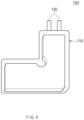
- FIG. 4 is a perspective view illustrating a sealing process in the method for manufacturing the secondary battery according to an embodiment of the present invention.
- a method for manufacturing a secondary battery according to an embodiment of the present invention may comprise a forming process of forming an accommodating part 112 in a pouch 110, a cutting process of cutting a portion of the pouch 110 adjacent to an inner corner portion in the accommodating part 112, and an accommodating process of accommodating an electrode assembly 120 into the pouch 110 after the forming process to manufacture a secondary battery 100.
- the method for manufacturing the secondary battery according to an embodiment of the present invention may further comprise a sealing process for sealing the pouch 110.
- a portion of the pouch 110 is slit-cut in an arc shape to form a cutting part 111.
- the cutting part 111 may be formed in consideration of a position at which the accommodating part 112 that accommodates the electrode assembly 120 will be formed in a subsequent process. That is, in the cutting process, the cutting part 111 may be formed at the portion of the pouch 110 adjacent to the inner corner portion 113 in the bent accommodating part 112.
- the cutting part 111 may be formed in an arc shape that is convex toward the inner corner portion 113 of the pouch 110 accommodating part 112.
- the cutting part 111 may be formed as an arc-shaped cutting line in the plan view.
- FIG. 5 is a plan view illustrating a first example of the cutting part formed on the pouch in the method for manufacturing the secondary battery according to an embodiment of the present invention
- FIG. 6 is a plan view illustrating a second example of the cutting part formed on the pouch in the method for manufacturing the secondary battery according to an embodiment of the present invention
- FIG. 7 is a plan view illustrating a third example of the cutting part formed on the pouch in the method for manufacturing the secondary battery according to an embodiment of the present invention.
- the arc-shaped cutting line of the cutting part 111 may be formed in an arc shape at an angle, for example, 60° to 285° (degrees) .
- the arc-shaped cutting line of the cutting part 111 may be formed at an angle of 60 degrees or more to effectively improve thinning of the pouch, and the cutting line may be formed at an angle of 285 degrees or less to prevent the portion of the pouch 110, which is cut as the arc-shaped cutting line, from being torn or separated, thereby realizing the thinning of the pouch.
- the arc-shaped cutting line of the cutting part 111 may be specifically formed, for example, in an arc shape at an angle of 120 degrees to 210 degrees.
- a radius of the arc of the cutting part 111 may be, for example, 4 mm to 12 mm.
- the arc-shaped cutting line of the cutting part 111 may be formed at an angle t1 of 120 degrees as a first example, and referring to FIG. 6 , the arc-shaped cutting line of the cutting part 111 may be formed at an angle t2 of 180 degrees as a second example. In addition, referring to FIG. 7 , the arc-shaped cutting line of the cutting part 111 may be formed at an angle t3 of 210 degrees as a third example.
- the cutting part 111 may be formed to be spaced a predetermined interval from the accommodating part 112. That is, in the cutting process, the cutting part 111 may formed to be spaced a predetermined interval from the accommodating part 112 in consideration of a position of the accommodating part 112 to be formed in the subsequent forming process. In this case, in the cutting process, for example, the interval b between the cutting part 111 and the accommodating part 112 may be formed to be 4 mm to 12 mm.
- the pouch 110 may comprise an aluminum (Al) material.
- the pouch 110 may comprise an aluminum layer and a resin layer.
- the accommodating part 112 having the bent shape may be formed in the pouch 110 to accommodate the bent electrode assembly 120 after the cutting process.
- the accommodating part 112 may be formed as, for example, a cup-shaped groove.
- the accommodating part 112 may be formed in an upwardly opened shape.
- the 'bent shape' does not mean that the electrode assembly 120 and the accommodating part 112 are bent by external force, but may mean, for example, a vertically extending shape.
- the accommodating part 112 may be formed in a shape corresponding to the electrode assembly 120.
- the accommodating part 112 may be formed by pressing the pouch 110 from the top to the bottom through a punch.
- the electrode assembly 120 may be formed in a shape bent at a right angle.
- the electrode assembly 120 may be formed to be bent in an "L" shape.
- the accommodating part 112 may be formed in a shape bent at a right angle. In this case, the forming process, the accommodating part 112 may be formed to be bent in an "L" shape.
- the inner corner portion 113 of the pouch 110 may be formed in a shape that is recessed in a direction of the accommodating part 112 in the plan view.
- the inner corner portion 113 may be formed, for example, in a shape that is recessed in a round shape.
- the arc-shaped cutting part 111 is formed at a distance adjacent to the inner corner portion 113 in the previous cutting process, an occurrence of excessive stress generated when the inner corner portion 113 is formed in a recessed shape in the forming process may be solved to effectively prevent cracks from occurring.
- the electrode assembly 120 is a power generating element that is chargeable and dischargeable and forms a structure in which electrodes and separators are combined and alternately stacked.
- the electrodes may comprise a positive electrode and a negative electrode. Also, each of the separators separates the positive electrode from the negative electrode to electrically insulate the positive electrode from the negative electrode.
- the separator is alternately stacked with the positive electrode and the negative electrode, which are made of insulation materials.
- each of the separator 114 may be, for example, a multi-layered film produced by microporous polyethylene, polypropylene, or a combination thereof or a polymer film for solid polymer electrolytes or gel-type polymer electrolytes such as polyvinylidene fluoride, polyethylene oxide, polyacrylonitrile, or polyvinylidene fluoride hexafluoropropylene copolymers.
- An electrode lead 130 may be connected to the electrode assembly 120 so as to be electrically connected to the outside. That is, the electrode lead 130 may be connected to the electrode of the electrode assembly 120 to electrically connect the electrode to an external terminal.
- the electrode assembly 120 may be accommodated in the accommodating part 112 of the pouch 110 after the forming process.
- an upper portion of the accommodating part 112 in which the electrode assembly 120 is accommodated may be covered. That is, the other side of the pouch 110 may be folded with respect to a folding line F of the pouch 110 to cover the accommodating part 112 formed at one side of the pouch 110 with respect to the folding line F of the pouch 110.
- an inner corner of the electrode assembly 120 may be formed in a shape corresponding to the inner corner portion 113 formed in the recessed shape in the pouch 110. That is, an inner corner portion of the electrode assembly 120 may be formed in a shape corresponding to the inner corner portion 113 formed in the recessed shape of the pouch 110.
- an outer circumferential surface of the pouch 110 may be sealed to seal the pouch 110.
- heat may be applied along an edge of the accommodating part 112 of the pouch 110 to form the sealing part.
- the sealing process may comprise a removing process of cutting and removing a portion remaining except for the accommodating part 112 and the sealing part.
- the cutting part 111 of the pouch 110 may be removed together.
- arc slit cutting may be performed in a section A adjacent to a portion at which the bent-shaped accommodating part 112 is formed in the pouch 110 to relieve an occurrence of stress generated in the adjacent section A of the bent-shaped accommodating part 112, thereby preventing cracks from occurring and improving a residual amount of aluminum.
- the secondary battery according to an embodiment of the present invention may be a product manufactured by the method for manufacturing the secondary battery according to the embodiment of the present invention, which is configured as described above.
- a portion of a pouch 110' was slit-cut in an arc shape to form a cutting part 111' to form a bent-shaped accommodating part 112.
- the cutting part 111' was formed in the portion of the pouch 110' adjacent to an inner corner portion of the bent accommodating part 112.
- the cutting part 111' was formed in an arc shape having an angle t1 of 120 degrees.
- the cutting part 111' was formed so that a radius R of the cutting part 111' is 8 mm, and a spaced distance b between the cutting part 111' and the accommodating part 112 is 8 mm.
- an angle t2 of a cutting part 111' ' of a pouch 110" is formed in an arc shape having an angle of 180 degrees.
- FIG. 8 is a plan view illustrating reference symbols of portions of the pouch that has undergone the cutting process and the forming process in the method for manufacturing the secondary battery according to an embodiment of the present invention
- FIG. 9 is an image illustrating a ratio of thinning at a portion P6 of the pouch illustrated in FIG. 8 .
Landscapes
- Chemical & Material Sciences (AREA)
- Chemical Kinetics & Catalysis (AREA)
- Electrochemistry (AREA)
- General Chemical & Material Sciences (AREA)
- Engineering & Computer Science (AREA)
- Manufacturing & Machinery (AREA)
- Sealing Battery Cases Or Jackets (AREA)
- Secondary Cells (AREA)
Abstract
Description
- The present application claims the benefit of the priority of
Korean Patent Application No. 10-2020-0140760, filed on October 27, 2020 - The present invention relates to a method for manufacturing a secondary battery and a secondary battery.
- Secondary batteries are rechargeable unlike primarily batteries, and also, the possibility of compact size and high capacity is high. Thus, recently, many studies on secondary batteries are being carried out. As technology development and demands for mobile devices increase, the demands for secondary batteries as energy sources are rapidly increasing.
- Rechargeable batteries are classified into coin type batteries, cylindrical type batteries, prismatic type batteries, and pouch type batteries according to a shape of a battery case. In such a secondary battery, an electrode assembly mounted in a battery case is a chargeable and dischargeable power generating device having a structure in which an electrode and a separator are stacked.
- Also, the electrode assembly may be approximately classified into a jelly-roll type electrode assembly in which a separator is interposed between a positive electrode and a negative electrode, each of which is provided as the form of a sheet coated with an active material, and then, the positive electrode, the separator, and the negative electrode are wound, a stacked type electrode assembly in which a plurality of positive and negative electrodes with a separator therebetween are sequentially stacked, and a stack/folding type electrode assembly in which stacked type unit cells are wound together with a separation film having a long length.
- Recently, the pouch-type battery in which a stack/folding type electrode assembly is built in a pouch-type battery case provided as an aluminum lamination sheet is attracting much attention due to its low manufacturing cost, light weight, easy shape deformation, and the like, and thus, its usage is gradually increasing.
- In the case of the L-shaped pouch-type battery, there have been cases in which pouch cracks occur in an L-shape section during pouch forming, and a criterion of a residual amount of aluminum (AL) is not satisfied.
- [Prior Art Document] (Patent Document)
Korean Patent Publication No. 10-2012-0067550 - One aspect of the present invention is to provide a method for manufacturing a secondary battery, which is capable of preventing cracks occurring in a bending section when forming from occurring and capable of improving a residual amount of aluminum.
- A method for manufacturing a secondary battery according to an embodiment of the present invention comprises: a cutting process of slit-cutting a portion of a pouch in an arc shape to form a cutting part; a forming process of forming an accommodating part in a bent shape to accommodate an electrode assembly having a bent shape in the pouch after the cutting process; and an accommodating process of accommodating the electrode assembly in the accommodating part of the pouch after the forming process, wherein, in the cutting process, the cutting part is formed at a portion of the pouch, which is adjacent to an inner corner portion in the accommodating part having the bent shape.
- A secondary battery according to an embodiment of the present invention may be a secondary battery manufactured through the method for manufacturing the secondary battery according the foregoing embodiment of the present invention.
- According to the present invention, when forming the pouch of the pouch-type secondary battery having the bent shape, the arc slit cut may be performed in the section adjacent to the accommodating part having the bent shape in the pouch to relieve the stress generated in the bent-shaped section and improve the residual amount of aluminum.
-
-
FIG. 1 is a plan view illustrating a cutting process in a method for manufacturing a secondary battery according to an embodiment of the present invention. -
FIG. 2 is a plan view illustrating a forming process in the method for manufacturing the secondary battery according to an embodiment of the present invention. -
FIG. 3 is a plan view illustrating an accommodating process in a method for manufacturing a secondary battery according to an embodiment of the present invention. -
FIG. 4 is a perspective view illustrating a sealing process in the method for manufacturing the secondary battery according to an embodiment of the present invention. -
FIG. 5 is a plan view illustrating a first example of a cutting part formed on a pouch in the method for manufacturing the secondary battery according to an embodiment of the present invention. -
FIG. 6 is a plan view illustrating a second example of the cutting part formed on the pouch in the method for manufacturing the secondary battery according to an embodiment of the present invention. -
FIG. 7 is a plan view illustrating a third example of the cutting part formed on the pouch in the method for manufacturing the secondary battery according to an embodiment of the present invention. -
FIG. 8 is a plan view illustrating reference symbols of portions of the pouch that has undergone the cutting process and the forming process in the method for manufacturing the secondary battery according to an embodiment of the present invention. -
FIG. 9 is an image illustrating a ratio of thinning at a portion P6 of the pouch illustrated inFIG. 8 . - The objectives, specific advantages, and novel features of the present invention will become more apparent from the following detailed description taken in conjunction with the accompanying drawings. It should be noted that the reference numerals are added to the components of the drawings in the present specification with the same numerals as possible, even if they are illustrated in other drawings. Also, the present invention may be embodied in different forms and should not be construed as limited to the embodiments set forth herein. In the following description of the present invention, the detailed descriptions of related arts which may unnecessarily obscure the gist of the present invention will be omitted.
-
FIG. 1 is a plan view illustrating a cutting process in a method for manufacturing a secondary battery according to an embodiment of the present invention,FIG. 2 is a plan view illustrating a forming process in the method for manufacturing the secondary battery according to an embodiment of the present invention,FIG. 3 is a plan view illustrating an accommodating process in a method for manufacturing a secondary battery according to an embodiment of the present invention, andFIG. 4 is a perspective view illustrating a sealing process in the method for manufacturing the secondary battery according to an embodiment of the present invention. - Referring to
FIGS. 1 to 4 , a method for manufacturing a secondary battery according to an embodiment of the present invention may comprise a forming process of forming anaccommodating part 112 in apouch 110, a cutting process of cutting a portion of thepouch 110 adjacent to an inner corner portion in theaccommodating part 112, and an accommodating process of accommodating anelectrode assembly 120 into thepouch 110 after the forming process to manufacture asecondary battery 100. In addition, the method for manufacturing the secondary battery according to an embodiment of the present invention may further comprise a sealing process for sealing thepouch 110. - Hereinafter, the method for manufacturing the secondary battery according to an embodiment of the present invention will be described in more detail.
- Referring to
FIGS. 1 and2 , in the cutting process, a portion of thepouch 110 is slit-cut in an arc shape to form acutting part 111. - Also, in the cutting process, the
cutting part 111 may be formed in consideration of a position at which theaccommodating part 112 that accommodates theelectrode assembly 120 will be formed in a subsequent process. That is, in the cutting process, thecutting part 111 may be formed at the portion of thepouch 110 adjacent to theinner corner portion 113 in the bentaccommodating part 112. - In addition, in the cutting process, the
cutting part 111 may be formed in an arc shape that is convex toward theinner corner portion 113 of thepouch 110 accommodatingpart 112. - In addition, in the cutting process, the
cutting part 111 may be formed as an arc-shaped cutting line in the plan view. -
FIG. 5 is a plan view illustrating a first example of the cutting part formed on the pouch in the method for manufacturing the secondary battery according to an embodiment of the present invention,FIG. 6 is a plan view illustrating a second example of the cutting part formed on the pouch in the method for manufacturing the secondary battery according to an embodiment of the present invention, andFIG. 7 is a plan view illustrating a third example of the cutting part formed on the pouch in the method for manufacturing the secondary battery according to an embodiment of the present invention. - Referring to
FIGS. 5 to 7 , in the cutting process, the arc-shaped cutting line of thecutting part 111 may be formed in an arc shape at an angle, for example, 60° to 285° (degrees) . Here, in the cutting process, the arc-shaped cutting line of thecutting part 111 may be formed at an angle of 60 degrees or more to effectively improve thinning of the pouch, and the cutting line may be formed at an angle of 285 degrees or less to prevent the portion of thepouch 110, which is cut as the arc-shaped cutting line, from being torn or separated, thereby realizing the thinning of the pouch. - Also, In the cutting process, the arc-shaped cutting line of the
cutting part 111 may be specifically formed, for example, in an arc shape at an angle of 120 degrees to 210 degrees. Here, in the cutting process, a radius of the arc of thecutting part 111 may be, for example, 4 mm to 12 mm. - More specifically, for example, referring to
FIG. 5 , in the cutting process, the arc-shaped cutting line of thecutting part 111 may be formed at an angle t1 of 120 degrees as a first example, and referring toFIG. 6 , the arc-shaped cutting line of thecutting part 111 may be formed at an angle t2 of 180 degrees as a second example. In addition, referring toFIG. 7 , the arc-shaped cutting line of thecutting part 111 may be formed at an angle t3 of 210 degrees as a third example. - In addition, in the cutting process, the
cutting part 111 may be formed to be spaced a predetermined interval from theaccommodating part 112. That is, in the cutting process, thecutting part 111 may formed to be spaced a predetermined interval from theaccommodating part 112 in consideration of a position of theaccommodating part 112 to be formed in the subsequent forming process. In this case, in the cutting process, for example, the interval b between thecutting part 111 and theaccommodating part 112 may be formed to be 4 mm to 12 mm. - The
pouch 110 may comprise an aluminum (Al) material. In this case, for example, thepouch 110 may comprise an aluminum layer and a resin layer. - Referring to
FIG. 2 , in the forming process, theaccommodating part 112 having the bent shape may be formed in thepouch 110 to accommodate thebent electrode assembly 120 after the cutting process. Here, theaccommodating part 112 may be formed as, for example, a cup-shaped groove. In this case, theaccommodating part 112 may be formed in an upwardly opened shape. Here, the 'bent shape' does not mean that theelectrode assembly 120 and theaccommodating part 112 are bent by external force, but may mean, for example, a vertically extending shape. - Furthermore, in the forming process, the
accommodating part 112 may be formed in a shape corresponding to theelectrode assembly 120. - In the forming process, for example, the
accommodating part 112 may be formed by pressing thepouch 110 from the top to the bottom through a punch. - Here, the
electrode assembly 120 may be formed in a shape bent at a right angle. In this case, theelectrode assembly 120 may be formed to be bent in an "L" shape. - In addition, in the forming process, the
accommodating part 112 may be formed in a shape bent at a right angle. In this case, the forming process, theaccommodating part 112 may be formed to be bent in an "L" shape. - In addition, in the forming process, the
inner corner portion 113 of thepouch 110 may be formed in a shape that is recessed in a direction of theaccommodating part 112 in the plan view. Here, theinner corner portion 113 may be formed, for example, in a shape that is recessed in a round shape. Here, as the arc-shapedcutting part 111 is formed at a distance adjacent to theinner corner portion 113 in the previous cutting process, an occurrence of excessive stress generated when theinner corner portion 113 is formed in a recessed shape in the forming process may be solved to effectively prevent cracks from occurring. - The
electrode assembly 120 is a power generating element that is chargeable and dischargeable and forms a structure in which electrodes and separators are combined and alternately stacked. - The electrodes may comprise a positive electrode and a negative electrode. Also, each of the separators separates the positive electrode from the negative electrode to electrically insulate the positive electrode from the negative electrode.
- The separator is alternately stacked with the positive electrode and the negative electrode, which are made of insulation materials.
- Also, each of the separator 114 may be, for example, a multi-layered film produced by microporous polyethylene, polypropylene, or a combination thereof or a polymer film for solid polymer electrolytes or gel-type polymer electrolytes such as polyvinylidene fluoride, polyethylene oxide, polyacrylonitrile, or polyvinylidene fluoride hexafluoropropylene copolymers.
- An
electrode lead 130 may be connected to theelectrode assembly 120 so as to be electrically connected to the outside. That is, theelectrode lead 130 may be connected to the electrode of theelectrode assembly 120 to electrically connect the electrode to an external terminal. - Referring to
FIG. 3 , in the accommodating process, theelectrode assembly 120 may be accommodated in theaccommodating part 112 of thepouch 110 after the forming process. - In addition, in the accommodating process, an upper portion of the
accommodating part 112 in which theelectrode assembly 120 is accommodated may be covered. That is, the other side of thepouch 110 may be folded with respect to a folding line F of thepouch 110 to cover theaccommodating part 112 formed at one side of thepouch 110 with respect to the folding line F of thepouch 110. - In addition, an inner corner of the
electrode assembly 120 may be formed in a shape corresponding to theinner corner portion 113 formed in the recessed shape in thepouch 110. That is, an inner corner portion of theelectrode assembly 120 may be formed in a shape corresponding to theinner corner portion 113 formed in the recessed shape of thepouch 110. - Referring to
FIG. 4 , in the sealing process, an outer circumferential surface of thepouch 110 may be sealed to seal thepouch 110. In this case, in the sealing process, heat may be applied along an edge of theaccommodating part 112 of thepouch 110 to form the sealing part. - In addition, the sealing process may comprise a removing process of cutting and removing a portion remaining except for the
accommodating part 112 and the sealing part. In this case, in the removing process, the cuttingpart 111 of thepouch 110 may be removed together. - Referring to
FIGS. 1 to 4 , in the method for manufacturing the secondary battery according to an embodiment of the present invention, which is configured as described above, when thepouch 110 of the pouch-type battery having the bent shape is formed, arc slit cutting may be performed in a section A adjacent to a portion at which the bent-shapedaccommodating part 112 is formed in thepouch 110 to relieve an occurrence of stress generated in the adjacent section A of the bent-shapedaccommodating part 112, thereby preventing cracks from occurring and improving a residual amount of aluminum. - Referring to
FIG. 4 , the secondary battery according to an embodiment of the present invention may be a product manufactured by the method for manufacturing the secondary battery according to the embodiment of the present invention, which is configured as described above. - Referring to
FIG. 5 , a portion of a pouch 110' was slit-cut in an arc shape to form a cutting part 111' to form a bent-shapedaccommodating part 112. Here, the cutting part 111' was formed in the portion of the pouch 110' adjacent to an inner corner portion of the bentaccommodating part 112. Here, the cutting part 111' was formed in an arc shape having an angle t1 of 120 degrees. The cutting part 111' was formed so that a radius R of the cutting part 111' is 8 mm, and a spaced distance b between the cutting part 111' and theaccommodating part 112 is 8 mm. - Referring to
FIG. 6 , the same process as in Manufacturing Example 1 was performed except that an angle t2 of a cutting part 111' ' of apouch 110" is formed in an arc shape having an angle of 180 degrees. - Referring to
FIG. 7 , the same process as in Manufacturing Example 1 was performed except that an angle t3 of a cuttingpart 111‴ of apouch 110"' is formed in an arc shape having an angle of 210 degrees. - The same process as in Manufacturing Example 1 was performed except that slit cutting is performed in a pouch to form a cutting part in a straight line shape.
-
FIG. 8 is a plan view illustrating reference symbols of portions of the pouch that has undergone the cutting process and the forming process in the method for manufacturing the secondary battery according to an embodiment of the present invention, andFIG. 9 is an image illustrating a ratio of thinning at a portion P6 of the pouch illustrated inFIG. 8 . - Here, FEA simulation was performed to measure a maximum thinning ratio of the pouch at each portion of the pouch illustrated in
FIG. 8 , and thus, the results were shown in Table 1 below. Then, the thinning ratio of the pouch at an inner corner portion P6 illustrated inFIG. 8 was measured, and an image ofFIG. 9 was shown. Here, the thinning of the pouch at the inner corner portion P6 in Comparative Example 1, Manufacturing Example 1, Manufacturing Example 2, and Manufacturing Example 3 in the order ofFIGS. 9(a), 9(b), 9 (c), and 9(d) (seeFIG. 8 ) .[Table 1] Round Slit Cutting Max, Thinning (%) P1 P2 P3 P4 P5 P6 Comparative Example 1 0° Straight 26.32 33.67 34.01 22.74 35.12 46.31 Manufacturing Example 1 120° 26.63 33.98 34.23 22.50 35.01 45.80 Manufacturing Example 2 180° 25.90 33.05 34.06 22.40 34.87 45.29 Manufacturing Example 3 210° 25.99 34.30 34.72 22.84 34.50 44.46 - Referring to Table 1, it is confirmed that an effect of thinning of the pouch in Manufacturing Examples 1 to 3, in which the arc slit cutting is performed, is improved compared to Comparative Example 1, in which the cutting part of the pouch is formed in the straight line shape. Particularly, it is seen that the thinning ratio of the pouch at the inner corner portion P6 of the pouch is 46.31% in Comparative Example 1, 45.80% in Manufacturing Example 1, 45.29% in Manufacturing Example 2, and 44.46% in Manufacturing Example 3. Here, it is seen that an amount of inflow from a portion P4 part to the portion P6 of the pouch increases, and thus, a thinning value of the pouch decreases to improve a residual amount of AI. That is, it is seen that an effect of the thinning of the pouch is improved by about 3.5% in Manufacturing Examples 1 to 3 when compared to that of the thinning of the pouch at the inner corner portion P6 of the pouch.
- While the present invention has been particularly shown and described with reference to exemplary embodiments thereof, it is to be understood that the scope of the present invention is not limited thereto. It will be understood by those of ordinary skill in the art that various changes in form and details may be made therein without departing from the spirit and scope of the present invention.
- Furthermore, the scope of protection of the present invention will be clarified by the appended claims.
-
- 100:
- Secondary battery
- 110:
- Pouch
- 111, 111', 111", 111‴:
- Cutting part
- 112:
- Accommodating part
- 113:
- Inner corner portion
- 120:
- Electrode assembly
- 130:
- Electrode lead
Claims (11)
- A method for manufacturing a secondary battery, the method comprising:a cutting process of slit-cutting a portion of a pouch in an arc shape to form a cutting part;a forming process of forming an accommodating part in a bent shape to accommodate an electrode assembly having a bent shape in the pouch after the cutting process; andan accommodating process of accommodating the electrode assembly in the accommodating part of the pouch after the forming process,wherein, in the cutting process, the cutting part is formed at a portion of the pouch, which is adjacent to an inner corner portion in the accommodating part having the bent shape.
- The method of claim 1, wherein the electrode assembly is formed in a shape bent at a right angle, and
in the forming process, the accommodating part is formed in a shape bent at a right angle. - The method of claim 1, wherein the electrode assembly is formed to be bent in an "L" shape, and
in the forming process, the accommodating part is formed to be bent in an "L" shape. - The method of claim 1, wherein, in the forming process, the accommodating part is formed in a shape corresponding to the electrode assembly.
- The method of claim 1, wherein, in the cutting process, the cutting part is formed in an arc shape that is convex toward the inner corner portion in the accommodating part having the bent shape in the pouch.
- The method of claim 5, wherein, in the cutting process, the cutting part is formed as an arc-shaped cutting line in a plan view.
- The method of claim 6, wherein, in the cutting process, the arc-shaped cutting line of the cutting part is formed in an arc shape having an angle of 60 degrees to 285 degrees.
- The method of claim 7, wherein, in the cutting process, the arc-shaped cutting line of the cutting part is formed in an arc shape having an angle of 120 degrees to 210 degrees.
- The method of claim 6, wherein, in the cutting process, the cutting part is formed to be spaced a predetermined interval from the accommodating part.
- The method of claim 1, wherein, in the forming process, the inner corner portion of the pouch is formed in a shape that is recessed in a direction of the accommodating part in a plan view.
- A secondary battery manufactured by the method for manufacturing the secondary battery of claims 1 to 10.
Applications Claiming Priority (2)
| Application Number | Priority Date | Filing Date | Title |
|---|---|---|---|
| KR1020200140760A KR102752537B1 (en) | 2020-10-27 | 2020-10-27 | Rechargeable battery manufacturing method and rechargeable battery |
| PCT/KR2021/015150 WO2022092785A1 (en) | 2020-10-27 | 2021-10-27 | Secondary battery manufacturing method and secondary battery |
Publications (3)
| Publication Number | Publication Date |
|---|---|
| EP4131589A1 true EP4131589A1 (en) | 2023-02-08 |
| EP4131589A4 EP4131589A4 (en) | 2025-01-08 |
| EP4131589B1 EP4131589B1 (en) | 2025-08-27 |
Family
ID=81382802
Family Applications (1)
| Application Number | Title | Priority Date | Filing Date |
|---|---|---|---|
| EP21886779.4A Active EP4131589B1 (en) | 2020-10-27 | 2021-10-27 | Secondary battery manufacturing method |
Country Status (9)
| Country | Link |
|---|---|
| US (1) | US20230307694A1 (en) |
| EP (1) | EP4131589B1 (en) |
| JP (1) | JP7475770B2 (en) |
| KR (1) | KR102752537B1 (en) |
| CN (1) | CN115485914A (en) |
| ES (1) | ES3040880T3 (en) |
| HU (1) | HUE072960T2 (en) |
| PL (1) | PL4131589T3 (en) |
| WO (1) | WO2022092785A1 (en) |
Family Cites Families (13)
| Publication number | Priority date | Publication date | Assignee | Title |
|---|---|---|---|---|
| CN1280155C (en) * | 2000-01-26 | 2006-10-18 | 大日本印刷株式会社 | heat sealing method |
| JP2005018990A (en) * | 2003-06-23 | 2005-01-20 | Ngk Spark Plug Co Ltd | Stacked lithium-ion secondary battery |
| KR100928128B1 (en) * | 2007-03-09 | 2009-11-25 | 삼성에스디아이 주식회사 | Secondary battery pouch manufacturing method and secondary battery pouch |
| KR101789067B1 (en) | 2010-12-16 | 2017-10-24 | 엘지디스플레이 주식회사 | Backlight unit and liquid crystal display using the same |
| KR101858317B1 (en) | 2015-05-07 | 2018-05-15 | 주식회사 엘지화학 | Pouch type secondary battery comprising a current interrupt electrode lead |
| CN204947022U (en) | 2015-09-24 | 2016-01-06 | 长城汽车股份有限公司 | Cell polar ear jockey and battery |
| KR101950464B1 (en) * | 2015-11-30 | 2019-02-20 | 주식회사 엘지화학 | Battery Cell of Irregular Structure with Improved Sealing Reliability of Cell Case |
| CN108885946A (en) * | 2016-03-28 | 2018-11-23 | 株式会社村田制作所 | Electric energy storage device and its manufacturing method |
| CN106129481B (en) | 2016-06-29 | 2019-02-05 | 珠海光宇电池有限公司 | The preparation method and battery core of takeup type spill battery core |
| KR102414770B1 (en) * | 2017-10-18 | 2022-06-30 | 주식회사 엘지에너지솔루션 | The Tape For Pouch And The Secondary Battery Attached The Thereof |
| US11114697B2 (en) * | 2018-09-04 | 2021-09-07 | Apple Inc. | Configurations for battery cell packaging |
| KR20200075989A (en) * | 2018-12-18 | 2020-06-29 | 주식회사 엘지화학 | The Battery Case, The Secondary Battery And The Method For Manufacturing Thereof |
| CN111261826B (en) * | 2020-03-25 | 2023-01-10 | 宁德新能源科技有限公司 | Electrode assembly, battery using same and electric device |
-
2020
- 2020-10-27 KR KR1020200140760A patent/KR102752537B1/en active Active
-
2021
- 2021-10-27 HU HUE21886779A patent/HUE072960T2/en unknown
- 2021-10-27 ES ES21886779T patent/ES3040880T3/en active Active
- 2021-10-27 WO PCT/KR2021/015150 patent/WO2022092785A1/en not_active Ceased
- 2021-10-27 US US17/923,416 patent/US20230307694A1/en active Pending
- 2021-10-27 CN CN202180031195.4A patent/CN115485914A/en active Pending
- 2021-10-27 EP EP21886779.4A patent/EP4131589B1/en active Active
- 2021-10-27 JP JP2023508580A patent/JP7475770B2/en active Active
- 2021-10-27 PL PL21886779.4T patent/PL4131589T3/en unknown
Also Published As
| Publication number | Publication date |
|---|---|
| PL4131589T3 (en) | 2025-11-12 |
| ES3040880T3 (en) | 2025-11-05 |
| EP4131589A4 (en) | 2025-01-08 |
| EP4131589B1 (en) | 2025-08-27 |
| KR102752537B1 (en) | 2025-01-10 |
| JP7475770B2 (en) | 2024-04-30 |
| JP2023536533A (en) | 2023-08-25 |
| KR20220056057A (en) | 2022-05-04 |
| HUE072960T2 (en) | 2025-12-28 |
| US20230307694A1 (en) | 2023-09-28 |
| CN115485914A (en) | 2022-12-16 |
| WO2022092785A1 (en) | 2022-05-05 |
Similar Documents
| Publication | Publication Date | Title |
|---|---|---|
| US11799122B2 (en) | Pouch for a secondary battery including a bridge and accommodation grooves | |
| US12057545B2 (en) | Pouch exterior material for secondary battery, pouch type secondary battery using the same, and method of manufacturing the same | |
| US10923758B2 (en) | Electrode assembly having step, secondary battery, battery pack and device including electrode assembly, and method of manufacturing electrode assembly | |
| KR101473145B1 (en) | Lectrode assembly, battery cell, manufacturing mathod of electrode assembly and manufacturing mathod of battery cell | |
| KR20130118716A (en) | Electrode assembly, battery cell and device comprising the same | |
| KR20170132565A (en) | Manufacturin method of rechargeable battery | |
| US12614793B2 (en) | Battery cell and battery cell manufacturing apparatus for manufacturing the same | |
| CN1574422A (en) | Jelly-roll type electrode assembly and secondary battery employing the same | |
| KR20140103402A (en) | Pouch for battery, and pouch type battery including the same | |
| CN108496270B (en) | Secondary battery | |
| US20230198106A1 (en) | Battery Cell Including Electrode Tab Having Stress Relief Portion | |
| EP4531191A1 (en) | Rechargeable battery | |
| EP4583264A1 (en) | Pouch-type battery case, manufacturing method therefor, and secondary battery manufacturing method | |
| EP4131589B1 (en) | Secondary battery manufacturing method | |
| EP4484132A1 (en) | Device for folding pouch for secondary battery and secondary battery |
Legal Events
| Date | Code | Title | Description |
|---|---|---|---|
| STAA | Information on the status of an ep patent application or granted ep patent |
Free format text: STATUS: THE INTERNATIONAL PUBLICATION HAS BEEN MADE |
|
| PUAI | Public reference made under article 153(3) epc to a published international application that has entered the european phase |
Free format text: ORIGINAL CODE: 0009012 |
|
| STAA | Information on the status of an ep patent application or granted ep patent |
Free format text: STATUS: REQUEST FOR EXAMINATION WAS MADE |
|
| 17P | Request for examination filed |
Effective date: 20221104 |
|
| AK | Designated contracting states |
Kind code of ref document: A1 Designated state(s): AL AT BE BG CH CY CZ DE DK EE ES FI FR GB GR HR HU IE IS IT LI LT LU LV MC MK MT NL NO PL PT RO RS SE SI SK SM TR |
|
| DAV | Request for validation of the european patent (deleted) | ||
| DAX | Request for extension of the european patent (deleted) | ||
| A4 | Supplementary search report drawn up and despatched |
Effective date: 20241205 |
|
| RIC1 | Information provided on ipc code assigned before grant |
Ipc: H01M 50/105 20210101ALI20241129BHEP Ipc: H01M 10/04 20060101ALI20241129BHEP Ipc: H01M 50/124 20210101ALI20241129BHEP Ipc: H01M 50/116 20210101AFI20241129BHEP |
|
| GRAP | Despatch of communication of intention to grant a patent |
Free format text: ORIGINAL CODE: EPIDOSNIGR1 |
|
| STAA | Information on the status of an ep patent application or granted ep patent |
Free format text: STATUS: GRANT OF PATENT IS INTENDED |
|
| INTG | Intention to grant announced |
Effective date: 20250610 |
|
| GRAS | Grant fee paid |
Free format text: ORIGINAL CODE: EPIDOSNIGR3 |
|
| GRAA | (expected) grant |
Free format text: ORIGINAL CODE: 0009210 |
|
| STAA | Information on the status of an ep patent application or granted ep patent |
Free format text: STATUS: THE PATENT HAS BEEN GRANTED |
|
| P01 | Opt-out of the competence of the unified patent court (upc) registered |
Free format text: CASE NUMBER: APP_31572/2025 Effective date: 20250701 |
|
| AK | Designated contracting states |
Kind code of ref document: B1 Designated state(s): AL AT BE BG CH CY CZ DE DK EE ES FI FR GB GR HR HU IE IS IT LI LT LU LV MC MK MT NL NO PL PT RO RS SE SI SK SM TR |
|
| REG | Reference to a national code |
Ref country code: CH Ref legal event code: EP |
|
| REG | Reference to a national code |
Ref country code: DE Ref legal event code: R096 Ref document number: 602021037438 Country of ref document: DE |
|
| REG | Reference to a national code |
Ref country code: IE Ref legal event code: FG4D |
|
| REG | Reference to a national code |
Ref country code: SE Ref legal event code: TRGR |
|
| PGFP | Annual fee paid to national office [announced via postgrant information from national office to epo] |
Ref country code: BE Payment date: 20250922 Year of fee payment: 5 Ref country code: GB Payment date: 20250922 Year of fee payment: 5 |
|
| PGFP | Annual fee paid to national office [announced via postgrant information from national office to epo] |
Ref country code: FR Payment date: 20250925 Year of fee payment: 5 |
|
| PGFP | Annual fee paid to national office [announced via postgrant information from national office to epo] |
Ref country code: SE Payment date: 20250923 Year of fee payment: 5 |
|
| REG | Reference to a national code |
Ref country code: ES Ref legal event code: FG2A Ref document number: 3040880 Country of ref document: ES Kind code of ref document: T3 Effective date: 20251105 |
|
| PGFP | Annual fee paid to national office [announced via postgrant information from national office to epo] |
Ref country code: HU Payment date: 20251127 Year of fee payment: 5 |
|
| REG | Reference to a national code |
Ref country code: HU Ref legal event code: AG4A Ref document number: E072960 Country of ref document: HU |
|
| REG | Reference to a national code |
Ref country code: NL Ref legal event code: MP Effective date: 20250827 |
|
| PG25 | Lapsed in a contracting state [announced via postgrant information from national office to epo] |
Ref country code: IS Free format text: LAPSE BECAUSE OF FAILURE TO SUBMIT A TRANSLATION OF THE DESCRIPTION OR TO PAY THE FEE WITHIN THE PRESCRIBED TIME-LIMIT Effective date: 20251227 |
|
| PGFP | Annual fee paid to national office [announced via postgrant information from national office to epo] |
Ref country code: DE Payment date: 20250922 Year of fee payment: 5 |
|
| PG25 | Lapsed in a contracting state [announced via postgrant information from national office to epo] |
Ref country code: NO Free format text: LAPSE BECAUSE OF FAILURE TO SUBMIT A TRANSLATION OF THE DESCRIPTION OR TO PAY THE FEE WITHIN THE PRESCRIBED TIME-LIMIT Effective date: 20251127 |
|
| REG | Reference to a national code |
Ref country code: LT Ref legal event code: MG9D |
|
| PG25 | Lapsed in a contracting state [announced via postgrant information from national office to epo] |
Ref country code: PT Free format text: LAPSE BECAUSE OF FAILURE TO SUBMIT A TRANSLATION OF THE DESCRIPTION OR TO PAY THE FEE WITHIN THE PRESCRIBED TIME-LIMIT Effective date: 20251229 |
|
| PG25 | Lapsed in a contracting state [announced via postgrant information from national office to epo] |
Ref country code: FI Free format text: LAPSE BECAUSE OF FAILURE TO SUBMIT A TRANSLATION OF THE DESCRIPTION OR TO PAY THE FEE WITHIN THE PRESCRIBED TIME-LIMIT Effective date: 20250827 |
|
| PG25 | Lapsed in a contracting state [announced via postgrant information from national office to epo] |
Ref country code: NL Free format text: LAPSE BECAUSE OF FAILURE TO SUBMIT A TRANSLATION OF THE DESCRIPTION OR TO PAY THE FEE WITHIN THE PRESCRIBED TIME-LIMIT Effective date: 20250827 Ref country code: HR Free format text: LAPSE BECAUSE OF FAILURE TO SUBMIT A TRANSLATION OF THE DESCRIPTION OR TO PAY THE FEE WITHIN THE PRESCRIBED TIME-LIMIT Effective date: 20250827 |
|
| PG25 | Lapsed in a contracting state [announced via postgrant information from national office to epo] |
Ref country code: GR Free format text: LAPSE BECAUSE OF FAILURE TO SUBMIT A TRANSLATION OF THE DESCRIPTION OR TO PAY THE FEE WITHIN THE PRESCRIBED TIME-LIMIT Effective date: 20251128 |
|
| PG25 | Lapsed in a contracting state [announced via postgrant information from national office to epo] |
Ref country code: LV Free format text: LAPSE BECAUSE OF FAILURE TO SUBMIT A TRANSLATION OF THE DESCRIPTION OR TO PAY THE FEE WITHIN THE PRESCRIBED TIME-LIMIT Effective date: 20250827 |
|
| PG25 | Lapsed in a contracting state [announced via postgrant information from national office to epo] |
Ref country code: BG Free format text: LAPSE BECAUSE OF FAILURE TO SUBMIT A TRANSLATION OF THE DESCRIPTION OR TO PAY THE FEE WITHIN THE PRESCRIBED TIME-LIMIT Effective date: 20250827 |
|
| PGFP | Annual fee paid to national office [announced via postgrant information from national office to epo] |
Ref country code: PL Payment date: 20250925 Year of fee payment: 5 |
|
| PG25 | Lapsed in a contracting state [announced via postgrant information from national office to epo] |
Ref country code: RS Free format text: LAPSE BECAUSE OF FAILURE TO SUBMIT A TRANSLATION OF THE DESCRIPTION OR TO PAY THE FEE WITHIN THE PRESCRIBED TIME-LIMIT Effective date: 20251127 |
|
| PGFP | Annual fee paid to national office [announced via postgrant information from national office to epo] |
Ref country code: ES Payment date: 20251117 Year of fee payment: 5 |
|
| REG | Reference to a national code |
Ref country code: AT Ref legal event code: MK05 Ref document number: 1831089 Country of ref document: AT Kind code of ref document: T Effective date: 20250827 |
|
| PG25 | Lapsed in a contracting state [announced via postgrant information from national office to epo] |
Ref country code: RO Free format text: LAPSE BECAUSE OF FAILURE TO SUBMIT A TRANSLATION OF THE DESCRIPTION OR TO PAY THE FEE WITHIN THE PRESCRIBED TIME-LIMIT Effective date: 20250827 |
|
| PG25 | Lapsed in a contracting state [announced via postgrant information from national office to epo] |
Ref country code: SM Free format text: LAPSE BECAUSE OF FAILURE TO SUBMIT A TRANSLATION OF THE DESCRIPTION OR TO PAY THE FEE WITHIN THE PRESCRIBED TIME-LIMIT Effective date: 20250827 |
|
| PG25 | Lapsed in a contracting state [announced via postgrant information from national office to epo] |
Ref country code: DK Free format text: LAPSE BECAUSE OF FAILURE TO SUBMIT A TRANSLATION OF THE DESCRIPTION OR TO PAY THE FEE WITHIN THE PRESCRIBED TIME-LIMIT Effective date: 20250827 |
|
| PG25 | Lapsed in a contracting state [announced via postgrant information from national office to epo] |
Ref country code: AT Free format text: LAPSE BECAUSE OF FAILURE TO SUBMIT A TRANSLATION OF THE DESCRIPTION OR TO PAY THE FEE WITHIN THE PRESCRIBED TIME-LIMIT Effective date: 20250827 |
|
| PG25 | Lapsed in a contracting state [announced via postgrant information from national office to epo] |
Ref country code: IT Free format text: LAPSE BECAUSE OF FAILURE TO SUBMIT A TRANSLATION OF THE DESCRIPTION OR TO PAY THE FEE WITHIN THE PRESCRIBED TIME-LIMIT Effective date: 20250827 |
|
| PG25 | Lapsed in a contracting state [announced via postgrant information from national office to epo] |
Ref country code: CZ Free format text: LAPSE BECAUSE OF FAILURE TO SUBMIT A TRANSLATION OF THE DESCRIPTION OR TO PAY THE FEE WITHIN THE PRESCRIBED TIME-LIMIT Effective date: 20250827 |
|
| PG25 | Lapsed in a contracting state [announced via postgrant information from national office to epo] |
Ref country code: EE Free format text: LAPSE BECAUSE OF FAILURE TO SUBMIT A TRANSLATION OF THE DESCRIPTION OR TO PAY THE FEE WITHIN THE PRESCRIBED TIME-LIMIT Effective date: 20250827 Ref country code: SK Free format text: LAPSE BECAUSE OF FAILURE TO SUBMIT A TRANSLATION OF THE DESCRIPTION OR TO PAY THE FEE WITHIN THE PRESCRIBED TIME-LIMIT Effective date: 20250827 |