EP4131584A1 - Battery module comprising heat insulating member - Google Patents
Battery module comprising heat insulating member Download PDFInfo
- Publication number
- EP4131584A1 EP4131584A1 EP21858529.7A EP21858529A EP4131584A1 EP 4131584 A1 EP4131584 A1 EP 4131584A1 EP 21858529 A EP21858529 A EP 21858529A EP 4131584 A1 EP4131584 A1 EP 4131584A1
- Authority
- EP
- European Patent Office
- Prior art keywords
- battery
- thermal insulation
- battery module
- battery cells
- insulation member
- Prior art date
- Legal status (The legal status is an assumption and is not a legal conclusion. Google has not performed a legal analysis and makes no representation as to the accuracy of the status listed.)
- Granted
Links
Images

Classifications
-
- H—ELECTRICITY
- H01—ELECTRIC ELEMENTS
- H01M—PROCESSES OR MEANS, e.g. BATTERIES, FOR THE DIRECT CONVERSION OF CHEMICAL ENERGY INTO ELECTRICAL ENERGY
- H01M10/00—Secondary cells; Manufacture thereof
- H01M10/60—Heating or cooling; Temperature control
- H01M10/65—Means for temperature control structurally associated with the cells
- H01M10/658—Means for temperature control structurally associated with the cells by thermal insulation or shielding
-
- H—ELECTRICITY
- H01—ELECTRIC ELEMENTS
- H01M—PROCESSES OR MEANS, e.g. BATTERIES, FOR THE DIRECT CONVERSION OF CHEMICAL ENERGY INTO ELECTRICAL ENERGY
- H01M10/00—Secondary cells; Manufacture thereof
- H01M10/60—Heating or cooling; Temperature control
- H01M10/61—Types of temperature control
- H01M10/613—Cooling or keeping cold
-
- H—ELECTRICITY
- H01—ELECTRIC ELEMENTS
- H01M—PROCESSES OR MEANS, e.g. BATTERIES, FOR THE DIRECT CONVERSION OF CHEMICAL ENERGY INTO ELECTRICAL ENERGY
- H01M10/00—Secondary cells; Manufacture thereof
- H01M10/60—Heating or cooling; Temperature control
- H01M10/64—Heating or cooling; Temperature control characterised by the shape of the cells
- H01M10/647—Prismatic or flat cells, e.g. pouch cells
-
- H—ELECTRICITY
- H01—ELECTRIC ELEMENTS
- H01M—PROCESSES OR MEANS, e.g. BATTERIES, FOR THE DIRECT CONVERSION OF CHEMICAL ENERGY INTO ELECTRICAL ENERGY
- H01M50/00—Constructional details or processes of manufacture of the non-active parts of electrochemical cells other than fuel cells, e.g. hybrid cells
- H01M50/20—Mountings; Secondary casings or frames; Racks, modules or packs; Suspension devices; Shock absorbers; Transport or carrying devices; Holders
- H01M50/204—Racks, modules or packs for multiple batteries or multiple cells
- H01M50/207—Racks, modules or packs for multiple batteries or multiple cells characterised by their shape
- H01M50/211—Racks, modules or packs for multiple batteries or multiple cells characterised by their shape adapted for pouch cells
-
- H—ELECTRICITY
- H01—ELECTRIC ELEMENTS
- H01M—PROCESSES OR MEANS, e.g. BATTERIES, FOR THE DIRECT CONVERSION OF CHEMICAL ENERGY INTO ELECTRICAL ENERGY
- H01M50/00—Constructional details or processes of manufacture of the non-active parts of electrochemical cells other than fuel cells, e.g. hybrid cells
- H01M50/20—Mountings; Secondary casings or frames; Racks, modules or packs; Suspension devices; Shock absorbers; Transport or carrying devices; Holders
- H01M50/233—Mountings; Secondary casings or frames; Racks, modules or packs; Suspension devices; Shock absorbers; Transport or carrying devices; Holders characterised by physical properties of casings or racks, e.g. dimensions
- H01M50/24—Mountings; Secondary casings or frames; Racks, modules or packs; Suspension devices; Shock absorbers; Transport or carrying devices; Holders characterised by physical properties of casings or racks, e.g. dimensions adapted for protecting batteries from their environment, e.g. from corrosion
-
- H—ELECTRICITY
- H01—ELECTRIC ELEMENTS
- H01M—PROCESSES OR MEANS, e.g. BATTERIES, FOR THE DIRECT CONVERSION OF CHEMICAL ENERGY INTO ELECTRICAL ENERGY
- H01M50/00—Constructional details or processes of manufacture of the non-active parts of electrochemical cells other than fuel cells, e.g. hybrid cells
- H01M50/20—Mountings; Secondary casings or frames; Racks, modules or packs; Suspension devices; Shock absorbers; Transport or carrying devices; Holders
- H01M50/289—Mountings; Secondary casings or frames; Racks, modules or packs; Suspension devices; Shock absorbers; Transport or carrying devices; Holders characterised by spacing elements or positioning means within frames, racks or packs
- H01M50/291—Mountings; Secondary casings or frames; Racks, modules or packs; Suspension devices; Shock absorbers; Transport or carrying devices; Holders characterised by spacing elements or positioning means within frames, racks or packs characterised by their shape
-
- H—ELECTRICITY
- H01—ELECTRIC ELEMENTS
- H01M—PROCESSES OR MEANS, e.g. BATTERIES, FOR THE DIRECT CONVERSION OF CHEMICAL ENERGY INTO ELECTRICAL ENERGY
- H01M50/00—Constructional details or processes of manufacture of the non-active parts of electrochemical cells other than fuel cells, e.g. hybrid cells
- H01M50/20—Mountings; Secondary casings or frames; Racks, modules or packs; Suspension devices; Shock absorbers; Transport or carrying devices; Holders
- H01M50/289—Mountings; Secondary casings or frames; Racks, modules or packs; Suspension devices; Shock absorbers; Transport or carrying devices; Holders characterised by spacing elements or positioning means within frames, racks or packs
- H01M50/293—Mountings; Secondary casings or frames; Racks, modules or packs; Suspension devices; Shock absorbers; Transport or carrying devices; Holders characterised by spacing elements or positioning means within frames, racks or packs characterised by the material
-
- H—ELECTRICITY
- H01—ELECTRIC ELEMENTS
- H01M—PROCESSES OR MEANS, e.g. BATTERIES, FOR THE DIRECT CONVERSION OF CHEMICAL ENERGY INTO ELECTRICAL ENERGY
- H01M50/00—Constructional details or processes of manufacture of the non-active parts of electrochemical cells other than fuel cells, e.g. hybrid cells
- H01M50/50—Current conducting connections for cells or batteries
- H01M50/502—Interconnectors for connecting terminals of adjacent batteries; Interconnectors for connecting cells outside a battery casing
- H01M50/505—Interconnectors for connecting terminals of adjacent batteries; Interconnectors for connecting cells outside a battery casing comprising a single busbar
-
- H—ELECTRICITY
- H01—ELECTRIC ELEMENTS
- H01M—PROCESSES OR MEANS, e.g. BATTERIES, FOR THE DIRECT CONVERSION OF CHEMICAL ENERGY INTO ELECTRICAL ENERGY
- H01M50/00—Constructional details or processes of manufacture of the non-active parts of electrochemical cells other than fuel cells, e.g. hybrid cells
- H01M50/50—Current conducting connections for cells or batteries
- H01M50/543—Terminals
- H01M50/547—Terminals characterised by the disposition of the terminals on the cells
- H01M50/548—Terminals characterised by the disposition of the terminals on the cells on opposite sides of the cell
-
- H—ELECTRICITY
- H01—ELECTRIC ELEMENTS
- H01M—PROCESSES OR MEANS, e.g. BATTERIES, FOR THE DIRECT CONVERSION OF CHEMICAL ENERGY INTO ELECTRICAL ENERGY
- H01M2200/00—Safety devices for primary or secondary batteries
- H01M2200/10—Temperature sensitive devices
-
- Y—GENERAL TAGGING OF NEW TECHNOLOGICAL DEVELOPMENTS; GENERAL TAGGING OF CROSS-SECTIONAL TECHNOLOGIES SPANNING OVER SEVERAL SECTIONS OF THE IPC; TECHNICAL SUBJECTS COVERED BY FORMER USPC CROSS-REFERENCE ART COLLECTIONS [XRACs] AND DIGESTS
- Y02—TECHNOLOGIES OR APPLICATIONS FOR MITIGATION OR ADAPTATION AGAINST CLIMATE CHANGE
- Y02E—REDUCTION OF GREENHOUSE GAS [GHG] EMISSIONS, RELATED TO ENERGY GENERATION, TRANSMISSION OR DISTRIBUTION
- Y02E60/00—Enabling technologies; Technologies with a potential or indirect contribution to GHG emissions mitigation
- Y02E60/10—Energy storage using batteries
Definitions
- the present invention relates to a battery module including a thermal insulation member having a composite structure capable of, even when thermal runaway occurs in a battery cell, preventing heat transfer to an adjacent battery cell.
- secondary batteries which are energy sources substituting for fossil fuels causing air pollution, have been applied to an electric vehicle (EV), a hybrid electric vehicle (HEV), a plug-in hybrid electric vehicle (P-HEV), and an energy storage system (ESS) .
- EV electric vehicle
- HEV hybrid electric vehicle
- P-HEV plug-in hybrid electric vehicle
- ESS energy storage system
- a lithium ion battery a lithium polymer battery, a nickel-cadmium battery, a nickel-hydride battery, and a nickel-zinc battery as secondary batteries that are widely used at present.
- the operating voltage of a unit secondary battery cell i.e. a unit battery cell, is about 2.0V to 5.0V.
- a plurality of battery cells may be connected to each other in series to constitute a battery cell assembly.
- battery cell assemblies may be connected to each other in series or in parallel to constitute a battery module depending on required output voltage or charge and discharge capacities.
- a battery pack is manufactured using at least one battery module by adding an additional component.
- the battery module is manufactured so as to have a structure in which the battery cells are disposed densely in the case in order to increase energy density thereof. When thermal runaway occurs in a specific battery cell, therefore, heat may be transferred to battery cells adjacent thereto.
- a thermal insulation material is provided between battery cells in order to prevent heat transfer between the battery cells and to prevent direct contact between the battery cells.
- the conventional thermal insulation material performs, for example, the function of a heat absorbing material having physical properties changed by heat generated when thermal runaway occurs in a battery cell, however, it is not possible to support battery cells and to interrupt heat transfer between the battery cells after thermal runaway occurs.
- a conventional thermal insulation material having a shape remaining unchanged after thermal runaway occurs is disposed in tight contact with a battery cell in which thermal runaway occurs.
- the present invention has been made in view of the above problems, and it is an object of the present invention to provide a battery module including a thermal insulation member having a composite structure capable of, even when thermal runaway occurs in a battery cell, preventing heat transfer to an adjacent battery cell and cooling the battery cell in which thermal runaway occurs.
- a battery module includes a plurality of battery cells, each battery cell of the plurality of battery cells having electrode leads, a case configured to receive the plurality of battery cells, and a thermal insulation member located between the plurality of battery cells, the thermal insulation member being configured to interrupt heat transfer between adjacent ones of the plurality of battery cells, wherein the thermal insulation member has a composite structure including an outer portion made of plastic having a lower melting point than temperature when thermal runaway occurs and a support member provided in an inner portion of the thermal insulation member, the support member being made of a heat-resistant material having a higher melting point than the temperature when the thermal runaway occurs.
- each of the plurality of battery cells may be a pouch-shaped battery cell having a structure in which two electrode leads, i.e. a positive electrode lead and a negative electrode lead, protrude in opposite directions.
- the case may include a lower case configured to receive the plurality of battery cells and the thermal insulation member and a cover located at the upper part of the lower case.
- the battery module according to the present invention may further include a busbar configured to electrically connect the electrode leads to each other.
- the thermal insulation member may be further provided between one of the plurality of battery cells and the case.
- the shape of the support member may be maintained even when the thermal runaway occurs to form an air layer between the plurality of battery cells.
- the support member may be made of one of metal and high heat-resistant polyamide-based plastic.
- the support member may have a plurality of protrusions formed on opposite surfaces of a thin plate.
- the support member may have rings which are joined to each other.
- a battery pack according to the present invention includes a battery module according to the present invention.
- a device according to the present invention includes a battery pack according to the present invention.
- a battery module according to the present invention has an advantage in that the battery module includes a thermal insulation member having a composite structure in which, when thermal runaway occurs in a battery cell, only a support member provided in the thermal insulation member remains unchanged to form an air layer between battery cells, whereby it is possible to maximize heat insulation and cooling effects while maintaining the distance between the battery cell in which thermal runaway occurs and battery cells adjacent thereto.
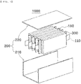
- FIG. 1 is an exploded perspective view of a battery module according to an embodiment of the present invention.
- the battery module 1000 includes a plurality of battery cells 100, each of which has electrode leads, a case 200 configured to receive the battery cells 100, and a thermal insulation member 300 located between the battery cells 100.
- each of the battery cells 100 may be a cylindrical battery cell, a prismatic battery cell, or a pouch-shaped battery cell.
- the battery module 1000 according to the present invention will be described with the focus on that the battery cell is a pouch-shaped battery cell 100.
- the pouch-shaped battery cell 100 includes a battery case having an electrode assembly received therein and a pair of electrode leads.
- the electrode assembly may be a jelly-roll type assembly, which is configured to have a structure in which a long sheet type positive electrode and a long sheet type negative electrode are wound in the state in which a separator is interposed therebetween, a stacked type electrode assembly, which is configured to have a structure in which a rectangular positive electrode and a rectangular negative electrode are stacked in the state in which a separator is interposed therebetween, a stacked and folded type assembly, which is configured to have a structure in which unit cells are wound using a long separation film, or a laminated and stacked type assembly, which is configured to have a structure in which unit cells are stacked in the state in which a separator is interposed therebetween and are then attached to each other.
- the present invention is not limited thereto.
- a solid electrolyte or a quasi-solid electrolyte manufactured by adding an additive to the solid electrolyte i.e. a gel-type electrolyte having an intermediate form between liquid and solid, may be used as an electrolyte, in addition to a liquid electrolyte, which is commonly used.
- the electrode assembly is received in the battery case, and the battery case is generally configured to have a laminate sheet structure including an inner layer, a metal layer, and an outer layer.
- the inner layer is disposed in direct contact with the electrode assembly, and therefore the inner layer must exhibit high insulation properties and high resistance to an electrolytic solution.
- the inner layer must exhibit high sealability in order to hermetically seal the battery case from the outside, i.e. a thermally-bonded sealed portion between inner layers must exhibit excellent thermal bonding strength.
- the inner layer may be made of a material selected from among a polyolefin-based resin, such as polypropylene, polyethylene, polyethylene acrylate, or polybutylene, a polyurethane resin, and a polyimide resin, which exhibit excellent chemical resistance and high sealability.
- a polyolefin-based resin such as polypropylene, polyethylene, polyethylene acrylate, or polybutylene, a polyurethane resin, and a polyimide resin, which exhibit excellent chemical resistance and high sealability.
- polypropylene which exhibits excellent mechanical-physical properties, such as tensile strength, rigidity, surface hardness, and impact resistance strength, and excellent chemical resistance, is the most preferably used.
- the metal layer which is disposed so as to abut the inner layer, corresponds to a barrier layer configured to prevent moisture or various kinds of gas from permeating into the battery from the outside.
- An aluminum thin film which is light and easily shapeable, may be used as a preferred material for the metal layer.
- the outer layer is provided on the other surface of the metal layer.
- the outer layer may be made of a heat-resistant polymer that exhibits excellent tensile strength, resistance to moisture permeation, and resistance to air permeation such that the outer layer exhibits high heat resistance and chemical resistance while protecting the electrode assembly.
- the outer layer may be made of nylon or polyethylene terephthalate.
- the present invention is not limited thereto.
- the pair of electrode leads 110 is constituted by a positive electrode lead and a negative electrode lead, which may be exposed from the battery case in a state of being electrically connected respectively to positive electrode tabs and negative electrode tabs of the cell assembly or may be directly connected to the cell assembly in the state in which tabs are omitted.
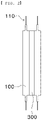
- the pouch-shaped battery cell 100 may be a unidirectional lead cell having a structure in which the electrode leads 110, i.e., the positive electrode lead and the negative electrode lead, protrude in the same direction or a bidirectional lead cell having a structure in which the positive electrode lead and the negative electrode lead protrude in opposite directions.
- the battery cell 100 according to the present invention is a pouch-shaped battery cell 100 having the structure of a bidirectional lead cell 100.
- the bidirectional lead cell 100 is generally longer in a direction in which the leads protrude than the unidirectional lead cell, and a member configured to support the battery cell 100 when the battery cell is received in the module is necessary due to the increased length thereof.
- the case 200 includes a lower case 210 configured to receive the battery cells 100 and the thermal insulation member 300 and a cover 220 located at the upper part of the lower case 210, the cover being configured to cover the upper part of the lower case after the battery cells 100 and the thermal insulation member 300 are received in the lower case.
- the battery module 1000 may further include various other components, such as a busbar configured to electrically connect the electrode leads to each other and a sensing board configured to sense voltage information of the battery cells.
- a busbar configured to electrically connect the electrode leads to each other
- a sensing board configured to sense voltage information of the battery cells.
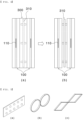
- FIG. 2 is a plan view showing a thermal insulation member located between the battery cells in the battery module according to the embodiment of the present invention
- FIG. 3 is a plan view showing a thermal insulation member located between the battery cell and the case in the battery module according to the embodiment of the present invention.
- the thermal insulation member 300 may be located between one of the battery cells 100 and another battery cell 100, or may be located between one of the battery cells 100 and another battery cell 100 and between each of the outermost battery cells 100 and a corresponding one of the side surfaces of the lower case 210, in which the battery cells are received.
- the thermal insulation member 300 may serve to insulate the battery cells 100 from each other while supporting the battery cells at a normal temperature, and may serve to prevent heat transfer between the battery cells 100 when thermal runaway occurs in any one of the battery cells.
- the shape of the thermal insulation member 300 is not particularly restricted, it is preferable for the thermal insulation member 300 to be formed so as to be disposed in tight contact with the side surface of the battery cell 100 that abut the thermal insulation member in consideration of energy density of the battery module 1000.
- the area of the side surface of the thermal insulation member 300 is shown as being equal to the area of the side surface of the portion of the battery cell 100 in which the electrode is received.
- the area of the side surface of the thermal insulation member 300 is not limited thereto and may be variously selected within a range in which the thermal insulation member 300 is capable of performing the function described in the present invention and the thermal insulation member does not interfere with other components of the battery module 1000.
- FIG. 4 is a front view showing shapes of a thermal insulation member according to an embodiment of the present invention before and after thermal runaway
- FIG. 5 is a perspective view showing various shapes of a support member according to an embodiment of the present invention.
- the thermal insulation member 300 is configured to have a composite structure including an outer portion made of plastic having a lower melting point than temperature when thermal runaway occurs and a support member 310 provided in an inner portion of the thermal insulation member, the support member being made of a heat-resistant material having a higher melting point than temperature when thermal runaway occurs.
- FIG. 5 shows a structure in which protrusions are formed on a thin plate, a structure in which thin bands each having a predetermined width are connected to each other in ring shapes, or a structure in which thin bands each having a predetermined width are connected to each other in quadrangular shapes as an example of the shape of the support member 310
- the support member 310 may be formed so as to have various shapes as long as the area of contact between the support member and the battery cell 100 is as small as possible within a range capable of supporting the battery cells 100.
- the structure in which the area of contact between the support member 310 and the battery cell 100 is as small as possible is advantageous in the aspect of thermal insulation.
- the support member 310 may be made of any of various well-known materials, such as metal, ceramics, and high heat-resistant plastic, as a heat-resistant material having a higher melting point than temperature when thermal runaway occurs. In consideration of ease and cost in manufacture of the support member 310 and the thermal insulation member 300 including the support member 310, however, it is preferable for the support member to be made of one of metal and high heat-resistant polyamide-based plastic.
- plastic constituting the outer portion of the thermal insulation member 300 having the support member 310 therein remains unchanged, whereby the thermal insulation member is disposed in tight contact with the battery cell 100 adjacent thereto over a large area.
- plastic constituting the outer portion of the thermal insulation member melts, whereby only the support member 310 provided in the thermal insulation member is left to support the battery cell 100 adjacent thereto over the minimum area.
- an air layer is formed between the battery cells 100 or between the battery cell 100 and the case 200, whereby thermal insulation performance may be improved.
- heat generated as the result of thermal runaway is discharged to the outside through convection in the air layer, whereby the function of cooling the battery cell 100 in which thermal runaway occurs may also be performed at the same time.
- the support member 310 according to the present invention is different from a conventional thermal insulation member in that the support member supports the battery cell 100 with the minimum contact area and the air layer that performs thermal insulation and cooling functions is formed between the battery cells 100 when thermal runaway occurs, unlike the conventional thermal insulation material, which performs the function of a thermal insulation material that interrupts heat transfer when thermal runaway occurs or performs the function of an absorbing material that absorbs heat.
Landscapes
- Chemical & Material Sciences (AREA)
- Chemical Kinetics & Catalysis (AREA)
- Electrochemistry (AREA)
- General Chemical & Material Sciences (AREA)
- Engineering & Computer Science (AREA)
- Manufacturing & Machinery (AREA)
- Secondary Cells (AREA)
- Battery Mounting, Suspending (AREA)
- Connection Of Batteries Or Terminals (AREA)
- Sealing Battery Cases Or Jackets (AREA)
Abstract
Description
- This application claims the benefit of priority to
Korean Patent Application No. 2020-0104768 filed on August 20, 2020 - The present invention relates to a battery module including a thermal insulation member having a composite structure capable of, even when thermal runaway occurs in a battery cell, preventing heat transfer to an adjacent battery cell.
- With technological development of mobile devices, such as smartphones, laptop computers, and digital cameras, and an increase in demand therefor, research on secondary batteries, which are capable of being charged and discharged, has been actively conducted. In addition, secondary batteries, which are energy sources substituting for fossil fuels causing air pollution, have been applied to an electric vehicle (EV), a hybrid electric vehicle (HEV), a plug-in hybrid electric vehicle (P-HEV), and an energy storage system (ESS) .
- There are a lithium ion battery, a lithium polymer battery, a nickel-cadmium battery, a nickel-hydride battery, and a nickel-zinc battery as secondary batteries that are widely used at present. The operating voltage of a unit secondary battery cell, i.e. a unit battery cell, is about 2.0V to 5.0V. In the case in which output voltage higher than the above operating voltage is required, therefore, a plurality of battery cells may be connected to each other in series to constitute a battery cell assembly. In addition, battery cell assemblies may be connected to each other in series or in parallel to constitute a battery module depending on required output voltage or charge and discharge capacities. In general, a battery pack is manufactured using at least one battery module by adding an additional component.
- The battery module is manufactured so as to have a structure in which the battery cells are disposed densely in the case in order to increase energy density thereof. When thermal runaway occurs in a specific battery cell, therefore, heat may be transferred to battery cells adjacent thereto.
- Meanwhile, conventionally, a thermal insulation material is provided between battery cells in order to prevent heat transfer between the battery cells and to prevent direct contact between the battery cells.
- In the case in which the conventional thermal insulation material performs, for example, the function of a heat absorbing material having physical properties changed by heat generated when thermal runaway occurs in a battery cell, however, it is not possible to support battery cells and to interrupt heat transfer between the battery cells after thermal runaway occurs.
- In addition, a conventional thermal insulation material having a shape remaining unchanged after thermal runaway occurs is disposed in tight contact with a battery cell in which thermal runaway occurs. As a result, it is difficult to discharge heat generated from the battery cell, whereby the battery cell is maintained in a high temperature state, and therefore heat may be transferred to battery cells adjacent thereto at a specific point in time.
- The present invention has been made in view of the above problems, and it is an object of the present invention to provide a battery module including a thermal insulation member having a composite structure capable of, even when thermal runaway occurs in a battery cell, preventing heat transfer to an adjacent battery cell and cooling the battery cell in which thermal runaway occurs.
- In order to accomplish the above object, a battery module according to the present invention includes a plurality of battery cells, each battery cell of the plurality of battery cells having electrode leads, a case configured to receive the plurality of battery cells, and a thermal insulation member located between the plurality of battery cells, the thermal insulation member being configured to interrupt heat transfer between adjacent ones of the plurality of battery cells, wherein the thermal insulation member has a composite structure including an outer portion made of plastic having a lower melting point than temperature when thermal runaway occurs and a support member provided in an inner portion of the thermal insulation member, the support member being made of a heat-resistant material having a higher melting point than the temperature when the thermal runaway occurs.
- Also, in the battery module according to the present invention, each of the plurality of battery cells may be a pouch-shaped battery cell having a structure in which two electrode leads, i.e. a positive electrode lead and a negative electrode lead, protrude in opposite directions.
- Also, in the battery module according to the present invention, the case may include a lower case configured to receive the plurality of battery cells and the thermal insulation member and a cover located at the upper part of the lower case.
- Also, the battery module according to the present invention may further include a busbar configured to electrically connect the electrode leads to each other.
- Also, in the battery module according to the present invention, the thermal insulation member may be further provided between one of the plurality of battery cells and the case.
- Also, in the battery module according to the present invention, the shape of the support member may be maintained even when the thermal runaway occurs to form an air layer between the plurality of battery cells.
- Also, in the battery module according to the present invention, the support member may be made of one of metal and high heat-resistant polyamide-based plastic.
- Also, in the battery module according to the present invention, the support member may have a plurality of protrusions formed on opposite surfaces of a thin plate.
- Also, in the battery module according to the present invention, the support member may have rings which are joined to each other.
- In addition, a battery pack according to the present invention includes a battery module according to the present invention.
- In addition, a device according to the present invention includes a battery pack according to the present invention.
- A battery module according to the present invention has an advantage in that the battery module includes a thermal insulation member having a composite structure in which, when thermal runaway occurs in a battery cell, only a support member provided in the thermal insulation member remains unchanged to form an air layer between battery cells, whereby it is possible to maximize heat insulation and cooling effects while maintaining the distance between the battery cell in which thermal runaway occurs and battery cells adjacent thereto.
-
-
FIG. 1 is an exploded perspective view of a battery module according to an embodiment of the present invention. -
FIG. 2 is a plan view showing a thermal insulation member located between battery cells in the battery module according to the embodiment of the present invention. -
FIG. 3 is a plan view showing a thermal insulation member located between a battery cell and a case in the battery module according to the embodiment of the present invention. -
FIG. 4 is a front view showing shapes of a thermal insulation member according to an embodiment of the present invention before and after thermal runaway. -
FIG. 5 is a perspective view showing various shapes of a support member according to an embodiment of the present invention. - In the present application, it should be understood that the terms "comprises," "has," "includes," etc. specify the presence of stated features, numbers, steps, operations, elements, components, or combinations thereof, but do not preclude the presence or addition of one or more other features, numbers, steps, operations, elements, components, or combinations thereof.
- In addition, the same reference numbers will be used throughout the drawings to refer to parts that perform similar functions or operations. In the case in which one part is said to be connected to another part in the specification, not only may the one part be directly connected to the other part, but also, the one part may be indirectly connected to the other part via a further part. In addition, that a certain element is included does not mean that other elements are excluded, but means that such elements may be further included unless mentioned otherwise.
- Hereinafter, a battery module according to the present invention will be described with reference to the accompanying drawings.
-
FIG. 1 is an exploded perspective view of a battery module according to an embodiment of the present invention. - When describing the
battery module 1000 according to the present invention in detail with reference toFIG. 1 , thebattery module 1000 includes a plurality ofbattery cells 100, each of which has electrode leads, acase 200 configured to receive thebattery cells 100, and athermal insulation member 300 located between thebattery cells 100. - Here, each of the
battery cells 100 may be a cylindrical battery cell, a prismatic battery cell, or a pouch-shaped battery cell. Hereinafter, thebattery module 1000 according to the present invention will be described with the focus on that the battery cell is a pouch-shaped battery cell 100. - The pouch-
shaped battery cell 100 includes a battery case having an electrode assembly received therein and a pair of electrode leads. - Here, the electrode assembly may be a jelly-roll type assembly, which is configured to have a structure in which a long sheet type positive electrode and a long sheet type negative electrode are wound in the state in which a separator is interposed therebetween, a stacked type electrode assembly, which is configured to have a structure in which a rectangular positive electrode and a rectangular negative electrode are stacked in the state in which a separator is interposed therebetween, a stacked and folded type assembly, which is configured to have a structure in which unit cells are wound using a long separation film, or a laminated and stacked type assembly, which is configured to have a structure in which unit cells are stacked in the state in which a separator is interposed therebetween and are then attached to each other. However, the present invention is not limited thereto.
- In addition, a solid electrolyte or a quasi-solid electrolyte manufactured by adding an additive to the solid electrolyte, i.e. a gel-type electrolyte having an intermediate form between liquid and solid, may be used as an electrolyte, in addition to a liquid electrolyte, which is commonly used.
- The electrode assembly is received in the battery case, and the battery case is generally configured to have a laminate sheet structure including an inner layer, a metal layer, and an outer layer. The inner layer is disposed in direct contact with the electrode assembly, and therefore the inner layer must exhibit high insulation properties and high resistance to an electrolytic solution. In addition, the inner layer must exhibit high sealability in order to hermetically seal the battery case from the outside, i.e. a thermally-bonded sealed portion between inner layers must exhibit excellent thermal bonding strength.
- The inner layer may be made of a material selected from among a polyolefin-based resin, such as polypropylene, polyethylene, polyethylene acrylate, or polybutylene, a polyurethane resin, and a polyimide resin, which exhibit excellent chemical resistance and high sealability. However, the present invention is not limited thereto, and polypropylene, which exhibits excellent mechanical-physical properties, such as tensile strength, rigidity, surface hardness, and impact resistance strength, and excellent chemical resistance, is the most preferably used.
- The metal layer, which is disposed so as to abut the inner layer, corresponds to a barrier layer configured to prevent moisture or various kinds of gas from permeating into the battery from the outside. An aluminum thin film, which is light and easily shapeable, may be used as a preferred material for the metal layer.
- The outer layer is provided on the other surface of the metal layer. The outer layer may be made of a heat-resistant polymer that exhibits excellent tensile strength, resistance to moisture permeation, and resistance to air permeation such that the outer layer exhibits high heat resistance and chemical resistance while protecting the electrode assembly. As an example, the outer layer may be made of nylon or polyethylene terephthalate. However, the present invention is not limited thereto.
- Meanwhile, the pair of electrode leads 110 is constituted by a positive electrode lead and a negative electrode lead, which may be exposed from the battery case in a state of being electrically connected respectively to positive electrode tabs and negative electrode tabs of the cell assembly or may be directly connected to the cell assembly in the state in which tabs are omitted.
- In addition, the pouch-
shaped battery cell 100 may be a unidirectional lead cell having a structure in which the electrode leads 110, i.e., the positive electrode lead and the negative electrode lead, protrude in the same direction or a bidirectional lead cell having a structure in which the positive electrode lead and the negative electrode lead protrude in opposite directions. - In particular, the following description will be given with the focus on that the
battery cell 100 according to the present invention is a pouch-shapedbattery cell 100 having the structure of a bidirectionallead cell 100. - The bidirectional
lead cell 100 is generally longer in a direction in which the leads protrude than the unidirectional lead cell, and a member configured to support thebattery cell 100 when the battery cell is received in the module is necessary due to the increased length thereof. - The
case 200 includes alower case 210 configured to receive thebattery cells 100 and thethermal insulation member 300 and acover 220 located at the upper part of thelower case 210, the cover being configured to cover the upper part of the lower case after thebattery cells 100 and thethermal insulation member 300 are received in the lower case. - In addition, the
battery module 1000 according to the present invention may further include various other components, such as a busbar configured to electrically connect the electrode leads to each other and a sensing board configured to sense voltage information of the battery cells. - Meanwhile,
FIG. 2 is a plan view showing a thermal insulation member located between the battery cells in the battery module according to the embodiment of the present invention, andFIG. 3 is a plan view showing a thermal insulation member located between the battery cell and the case in the battery module according to the embodiment of the present invention. - When describing the position at which the
thermal insulation member 300 is provided in thebattery module 1000 with reference toFIGS. 2 and3 , thethermal insulation member 300 may be located between one of thebattery cells 100 and anotherbattery cell 100, or may be located between one of thebattery cells 100 and anotherbattery cell 100 and between each of theoutermost battery cells 100 and a corresponding one of the side surfaces of thelower case 210, in which the battery cells are received. - Since the thermal insulation member is located as described above, the
thermal insulation member 300 may serve to insulate thebattery cells 100 from each other while supporting the battery cells at a normal temperature, and may serve to prevent heat transfer between thebattery cells 100 when thermal runaway occurs in any one of the battery cells. - Meanwhile, although the shape of the
thermal insulation member 300 is not particularly restricted, it is preferable for thethermal insulation member 300 to be formed so as to be disposed in tight contact with the side surface of thebattery cell 100 that abut the thermal insulation member in consideration of energy density of thebattery module 1000. - Also, in the present invention, the area of the side surface of the
thermal insulation member 300 is shown as being equal to the area of the side surface of the portion of thebattery cell 100 in which the electrode is received. However, the area of the side surface of thethermal insulation member 300 is not limited thereto and may be variously selected within a range in which thethermal insulation member 300 is capable of performing the function described in the present invention and the thermal insulation member does not interfere with other components of thebattery module 1000. -
FIG. 4 is a front view showing shapes of a thermal insulation member according to an embodiment of the present invention before and after thermal runaway, andFIG. 5 is a perspective view showing various shapes of a support member according to an embodiment of the present invention. - When describing the structure of the
thermal insulation member 300 according to the present invention and the behavior of the thermal insulation member when thermal runaway occurs in detail with reference toFIGS. 4 and 5 , thethermal insulation member 300 is configured to have a composite structure including an outer portion made of plastic having a lower melting point than temperature when thermal runaway occurs and asupport member 310 provided in an inner portion of the thermal insulation member, the support member being made of a heat-resistant material having a higher melting point than temperature when thermal runaway occurs. - Meanwhile, although
FIG. 5 shows a structure in which protrusions are formed on a thin plate, a structure in which thin bands each having a predetermined width are connected to each other in ring shapes, or a structure in which thin bands each having a predetermined width are connected to each other in quadrangular shapes as an example of the shape of thesupport member 310, thesupport member 310 may be formed so as to have various shapes as long as the area of contact between the support member and thebattery cell 100 is as small as possible within a range capable of supporting thebattery cells 100. - When the area of contact between the
support member 310 and thebattery cell 100 is increased, a possibility of heat transfer to anadjacent battery cell 100 via thesupport member 310 is increased. Consequently, the structure in which the area of contact between thesupport member 310 and thebattery cell 100 is as small as possible is advantageous in the aspect of thermal insulation. - In addition, the
support member 310 may be made of any of various well-known materials, such as metal, ceramics, and high heat-resistant plastic, as a heat-resistant material having a higher melting point than temperature when thermal runaway occurs. In consideration of ease and cost in manufacture of thesupport member 310 and thethermal insulation member 300 including thesupport member 310, however, it is preferable for the support member to be made of one of metal and high heat-resistant polyamide-based plastic. - When the temperature of the
battery cell 100 is normal, plastic constituting the outer portion of thethermal insulation member 300 having thesupport member 310 therein remains unchanged, whereby the thermal insulation member is disposed in tight contact with thebattery cell 100 adjacent thereto over a large area. When thermal runaway occurs, however, plastic constituting the outer portion of the thermal insulation member melts, whereby only thesupport member 310 provided in the thermal insulation member is left to support thebattery cell 100 adjacent thereto over the minimum area. - As a result, an air layer is formed between the
battery cells 100 or between thebattery cell 100 and thecase 200, whereby thermal insulation performance may be improved. In addition, heat generated as the result of thermal runaway is discharged to the outside through convection in the air layer, whereby the function of cooling thebattery cell 100 in which thermal runaway occurs may also be performed at the same time. - That is, the
support member 310 according to the present invention is different from a conventional thermal insulation member in that the support member supports thebattery cell 100 with the minimum contact area and the air layer that performs thermal insulation and cooling functions is formed between thebattery cells 100 when thermal runaway occurs, unlike the conventional thermal insulation material, which performs the function of a thermal insulation material that interrupts heat transfer when thermal runaway occurs or performs the function of an absorbing material that absorbs heat. - Although the specific details of the present invention have been described in detail, those skilled in the art will appreciate that the detailed description thereof discloses only preferred embodiments of the present invention and thus does not limit the scope of the present invention. Accordingly, those skilled in the art will appreciate that various changes and modifications are possible, without departing from the category and technical idea of the present invention, and it will be obvious that such changes and modifications fall within the scope of the appended claims.
-
- 1000:
- Battery module
- 100:
- Battery cell
- 110:
- Electrode lead
- 200:
- Case
- 210:
- Lower case
- 220:
- Cover
- 300:
- Thermal insulation member
- 310:
- Support member
Claims (11)
- A battery module (1000) capable of, when thermal runaway occurs in a battery cell (100), preventing heat transfer to an adjacent battery cell (100), the battery module (1000) comprising:a plurality of battery cells (100), each battery cell of the plurality of battery cells having electrode leads (110) ;a case (200) configured to receive the plurality of battery cells (100); anda thermal insulation member (300) located between the plurality of battery cells (100), the thermal insulation member being configured to interrupt heat transfer between adjacent ones of the plurality of battery cells (100),wherein the thermal insulation member (300) has a composite structure comprising an outer portion made of plastic having a lower melting point than a temperature when the thermal runaway occurs and a support member (310) provided in an inner portion of the thermal insulation member, the support member being made of a heat-resistant material having a higher melting point than the temperature when the thermal runaway occurs.
- The battery module (1000) according to claim 1, wherein each of the plurality of battery cells (100) is a pouch-shaped battery cell (100) having a structure in which two electrode leads (110), i.e. a positive electrode lead and a negative electrode lead, protrude in opposite directions.
- The battery module (1000) according to claim 1, wherein the case (200) comprises:A lower case (210) configured to receive the plurality of battery cells (100) and the thermal insulation member (300); anda cover (220) located at an upper part of the lower case (210) .
- The battery module (1000) according to claim 3, further comprising a busbar configured to electrically connect the electrode leads (110) to each other.
- The battery module (1000) according to claim 1, wherein the thermal insulation member (300) is further provided between one of the plurality of battery cells (100) and the case (200).
- The battery module (1000) according to claim 1, wherein a shape of the support member (310) is maintained even when the thermal runaway occurs to form an air layer between the plurality of battery cells (100).
- The battery module (1000) according to claim 6, wherein the support member (310) is made of one of metal and high heat-resistant polyamide-based plastic.
- The battery module (1000) according to claim 7, wherein the support member (310) has a plurality of protrusions formed on opposite surfaces of a thin plate.
- The battery module (1000) according to claim 7, wherein the support member (310) has rings which are joined to each other.
- A battery pack comprising the battery module (1000) according to any one of claims 1 to 9.
- A device comprising the battery pack according to claim 10.
Applications Claiming Priority (2)
| Application Number | Priority Date | Filing Date | Title |
|---|---|---|---|
| KR1020200104768A KR102869313B1 (en) | 2020-08-20 | 2020-08-20 | Battery module including heat insulating member |
| PCT/KR2021/010732 WO2022039442A1 (en) | 2020-08-20 | 2021-08-12 | Battery module comprising heat insulating member |
Publications (3)
| Publication Number | Publication Date |
|---|---|
| EP4131584A1 true EP4131584A1 (en) | 2023-02-08 |
| EP4131584A4 EP4131584A4 (en) | 2024-08-14 |
| EP4131584B1 EP4131584B1 (en) | 2025-05-28 |
Family
ID=80323578
Family Applications (1)
| Application Number | Title | Priority Date | Filing Date |
|---|---|---|---|
| EP21858529.7A Active EP4131584B1 (en) | 2020-08-20 | 2021-08-12 | Battery module including thermal insulation member |
Country Status (8)
| Country | Link |
|---|---|
| US (1) | US12609379B2 (en) |
| EP (1) | EP4131584B1 (en) |
| JP (1) | JP7508173B2 (en) |
| KR (1) | KR102869313B1 (en) |
| CN (1) | CN115485911A (en) |
| ES (1) | ES3033853T3 (en) |
| HU (1) | HUE071738T2 (en) |
| WO (1) | WO2022039442A1 (en) |
Families Citing this family (10)
| Publication number | Priority date | Publication date | Assignee | Title |
|---|---|---|---|---|
| KR102674208B1 (en) | 2021-12-30 | 2024-06-12 | 에스케이온 주식회사 | Battery module and battery pack comprising the same |
| JP7719205B2 (en) * | 2022-04-25 | 2025-08-05 | エルジー エナジー ソリューション リミテッド | Battery module, battery pack and automobile including the same |
| EP4345994A4 (en) * | 2022-04-27 | 2025-02-12 | LG Energy Solution, Ltd. | Battery module, battery pack and vehicle including same |
| WO2024019399A1 (en) * | 2022-07-20 | 2024-01-25 | 주식회사 엘지에너지솔루션 | Battery pack, battery module and vehicle including same |
| US20250062446A1 (en) * | 2022-08-29 | 2025-02-20 | Lg Energy Solution, Ltd. | Battery pack having improved safety |
| WO2024144085A1 (en) * | 2022-12-26 | 2024-07-04 | 주식회사 엘지에너지솔루션 | Cell module assembly and battery pack including same |
| KR20240123671A (en) * | 2023-02-07 | 2024-08-14 | 주식회사 엘지에너지솔루션 | Cell stack assembly and battery pack including the same |
| US20240339710A1 (en) * | 2023-04-10 | 2024-10-10 | GM Global Technology Operations LLC | Segmented battery cell mounting plate for thermal runaway mitigation |
| KR20250049723A (en) * | 2023-10-05 | 2025-04-14 | 주식회사 엘지에너지솔루션 | Thermal barrier for secondary battery and battery pack comprising the same |
| CN121601887A (en) * | 2024-08-21 | 2026-03-03 | Sk新能源株式会社 | Battery assembly |
Family Cites Families (26)
| Publication number | Priority date | Publication date | Assignee | Title |
|---|---|---|---|---|
| KR100948002B1 (en) * | 2006-03-06 | 2010-03-18 | 주식회사 엘지화학 | Medium and large battery module |
| KR101244736B1 (en) | 2006-08-17 | 2013-03-18 | 삼성에스디아이 주식회사 | Battery module |
| JP5326480B2 (en) * | 2008-10-14 | 2013-10-30 | トヨタ自動車株式会社 | Power storage device |
| US7736799B1 (en) | 2009-07-17 | 2010-06-15 | Tesla Motors, Inc. | Method and apparatus for maintaining cell wall integrity during thermal runaway using an outer layer of intumescent material |
| US8304108B2 (en) | 2009-07-17 | 2012-11-06 | Tesla Motors, Inc. | Method and apparatus for maintaining cell wall integrity using a high yield strength outer sleeve |
| US8263254B2 (en) | 2009-07-17 | 2012-09-11 | Tesla Motors, Inc. | Cell with an outer layer of intumescent material |
| KR101281811B1 (en) | 2010-08-16 | 2013-07-15 | 주식회사 엘지화학 | Battery Pack Having Improved Structure Stability |
| JP6041443B2 (en) * | 2010-11-05 | 2016-12-07 | エルジー・ケム・リミテッド | Secondary battery with improved safety |
| JP2012124319A (en) * | 2010-12-08 | 2012-06-28 | Jm Energy Corp | Power storage device |
| US9142809B2 (en) | 2011-01-04 | 2015-09-22 | Samsung Sdi Co., Ltd. | Battery module |
| JP5486623B2 (en) | 2012-03-09 | 2014-05-07 | 豊田合成株式会社 | Battery holder |
| KR101255250B1 (en) * | 2012-03-23 | 2013-04-16 | 삼성에스디아이 주식회사 | Battery module |
| JP6171332B2 (en) | 2012-12-26 | 2017-08-02 | 日産自動車株式会社 | Battery module |
| KR101730961B1 (en) | 2013-01-04 | 2017-04-27 | 삼성에스디아이 주식회사 | Battery module having heat insulating member |
| JP6608653B2 (en) * | 2015-09-02 | 2019-11-20 | 株式会社東芝 | Battery module |
| EP3327817B1 (en) | 2016-11-29 | 2019-11-06 | Samsung SDI Co., Ltd. | Wall structure of a battery cell, battery submodule, battery module or battery system |
| CN207587926U (en) | 2016-11-29 | 2018-07-06 | 北京科易动力科技有限公司 | The heat absorption heat insulation structural of battery module |
| JP6885791B2 (en) | 2017-06-05 | 2021-06-16 | 積水化学工業株式会社 | Thermal runaway prevention sheet |
| DE102017008102A1 (en) * | 2017-08-29 | 2019-02-28 | Carl Freudenberg Kg | Energy storage system |
| US11437664B2 (en) | 2017-09-22 | 2022-09-06 | Panasonic Intellectual Property Management Co., Ltd. | Battery module |
| EP3780254A4 (en) * | 2018-03-30 | 2021-05-19 | SANYO Electric Co., Ltd. | Power supply device, electric vehicle provided with said power supply device, and electricity-storage device |
| KR102328730B1 (en) | 2018-04-20 | 2021-11-17 | 주식회사 엘지에너지솔루션 | A battery module having a structure facilitating connection in series/parallel and a battery pack comprising the same |
| CN112385071B (en) | 2018-07-09 | 2024-09-20 | 三洋电机株式会社 | Battery system, electric vehicle having the same, and power storage device |
| JP7074019B2 (en) * | 2018-10-24 | 2022-05-24 | トヨタ自動車株式会社 | Power storage device |
| DE102019202560A1 (en) | 2019-02-26 | 2020-08-27 | Hyundai Motor Company | EXHAUST GAS AFTER-TREATMENT SYSTEM AND METHOD, VEHICLE AND METHOD OF OPERATING A VEHICLE |
| CN210668459U (en) | 2019-08-20 | 2020-06-02 | 深圳安凯利电池有限公司 | Explosion-proof flame retardant structure of lithium cell |
-
2020
- 2020-08-20 KR KR1020200104768A patent/KR102869313B1/en active Active
-
2021
- 2021-08-12 WO PCT/KR2021/010732 patent/WO2022039442A1/en not_active Ceased
- 2021-08-12 CN CN202180031538.7A patent/CN115485911A/en active Pending
- 2021-08-12 ES ES21858529T patent/ES3033853T3/en active Active
- 2021-08-12 US US17/921,857 patent/US12609379B2/en active Active
- 2021-08-12 JP JP2022566246A patent/JP7508173B2/en active Active
- 2021-08-12 EP EP21858529.7A patent/EP4131584B1/en active Active
- 2021-08-12 HU HUE21858529A patent/HUE071738T2/en unknown
Also Published As
| Publication number | Publication date |
|---|---|
| ES3033853T3 (en) | 2025-08-08 |
| CN115485911A (en) | 2022-12-16 |
| WO2022039442A1 (en) | 2022-02-24 |
| KR20220023191A (en) | 2022-03-02 |
| US12609379B2 (en) | 2026-04-21 |
| HUE071738T2 (en) | 2025-09-28 |
| EP4131584A4 (en) | 2024-08-14 |
| JP7508173B2 (en) | 2024-07-01 |
| EP4131584B1 (en) | 2025-05-28 |
| KR102869313B1 (en) | 2025-10-13 |
| US20230178824A1 (en) | 2023-06-08 |
| JP2023524706A (en) | 2023-06-13 |
Similar Documents
| Publication | Publication Date | Title |
|---|---|---|
| US12609379B2 (en) | Battery module including thermal insulation member | |
| US20250379310A1 (en) | Battery module capable of preventing movement of gas to adjacent module | |
| EP4191750B1 (en) | Battery pack with improved cooling performance and device comprising same | |
| JP7701117B2 (en) | Battery module with electrolyte leakage detection function and battery pack including the same | |
| EP4250449A1 (en) | Pouch-type battery cell having improved safety, and battery module comprising same | |
| EP4113733B1 (en) | Battery cell including electrode tab having stress relief portion | |
| KR102711924B1 (en) | Battery module having structure for preventing degradation and Battery pack having the same | |
| KR20220014723A (en) | Battery cell assembly with cooling fins and cooling tube | |
| KR102767817B1 (en) | A battery pack comprising a contact-type cooling plate and device with it | |
| EP4210162B1 (en) | Pouch-shaped battery cell having safety element provided between electrode lead and lead film | |
| EP4243194B1 (en) | Pouch-shaped battery cell with improved thermal stability | |
| US20240421423A1 (en) | Secondary Battery and Battery Module Including the Same | |
| KR20230071572A (en) | Battery Stack with Improved Cooling Ability And Battery Module Using The Same | |
| KR20220039437A (en) | Cell Module Having Uniform Temperature Distribution and method for Manufacturing Same | |
| KR20220036236A (en) | Battery module including battery cells with electrode leads of different thicknesses |
Legal Events
| Date | Code | Title | Description |
|---|---|---|---|
| STAA | Information on the status of an ep patent application or granted ep patent |
Free format text: STATUS: THE INTERNATIONAL PUBLICATION HAS BEEN MADE |
|
| PUAI | Public reference made under article 153(3) epc to a published international application that has entered the european phase |
Free format text: ORIGINAL CODE: 0009012 |
|
| STAA | Information on the status of an ep patent application or granted ep patent |
Free format text: STATUS: REQUEST FOR EXAMINATION WAS MADE |
|
| 17P | Request for examination filed |
Effective date: 20221104 |
|
| AK | Designated contracting states |
Kind code of ref document: A1 Designated state(s): AL AT BE BG CH CY CZ DE DK EE ES FI FR GB GR HR HU IE IS IT LI LT LU LV MC MK MT NL NO PL PT RO RS SE SI SK SM TR |
|
| DAV | Request for validation of the european patent (deleted) | ||
| DAX | Request for extension of the european patent (deleted) | ||
| A4 | Supplementary search report drawn up and despatched |
Effective date: 20240717 |
|
| RIC1 | Information provided on ipc code assigned before grant |
Ipc: H01M 50/505 20210101ALI20240711BHEP Ipc: H01M 50/548 20210101ALI20240711BHEP Ipc: H01M 50/293 20210101ALI20240711BHEP Ipc: H01M 50/291 20210101ALI20240711BHEP Ipc: H01M 50/211 20210101ALI20240711BHEP Ipc: H01M 50/24 20210101ALI20240711BHEP Ipc: H01M 10/647 20140101ALI20240711BHEP Ipc: H01M 10/658 20140101AFI20240711BHEP |
|
| GRAP | Despatch of communication of intention to grant a patent |
Free format text: ORIGINAL CODE: EPIDOSNIGR1 |
|
| STAA | Information on the status of an ep patent application or granted ep patent |
Free format text: STATUS: GRANT OF PATENT IS INTENDED |
|
| INTG | Intention to grant announced |
Effective date: 20250102 |
|
| P01 | Opt-out of the competence of the unified patent court (upc) registered |
Free format text: CASE NUMBER: APP_584/2025 Effective date: 20250107 |
|
| GRAS | Grant fee paid |
Free format text: ORIGINAL CODE: EPIDOSNIGR3 |
|
| GRAA | (expected) grant |
Free format text: ORIGINAL CODE: 0009210 |
|
| STAA | Information on the status of an ep patent application or granted ep patent |
Free format text: STATUS: THE PATENT HAS BEEN GRANTED |
|
| AK | Designated contracting states |
Kind code of ref document: B1 Designated state(s): AL AT BE BG CH CY CZ DE DK EE ES FI FR GB GR HR HU IE IS IT LI LT LU LV MC MK MT NL NO PL PT RO RS SE SI SK SM TR |
|
| REG | Reference to a national code |
Ref country code: GB Ref legal event code: FG4D |
|
| REG | Reference to a national code |
Ref country code: CH Ref legal event code: EP |
|
| REG | Reference to a national code |
Ref country code: IE Ref legal event code: FG4D Ref country code: DE Ref legal event code: R096 Ref document number: 602021031519 Country of ref document: DE |
|
| REG | Reference to a national code |
Ref country code: ES Ref legal event code: FG2A Ref document number: 3033853 Country of ref document: ES Kind code of ref document: T3 Effective date: 20250808 |
|
| PGFP | Annual fee paid to national office [announced via postgrant information from national office to epo] |
Ref country code: HU Payment date: 20250827 Year of fee payment: 5 |
|
| REG | Reference to a national code |
Ref country code: HU Ref legal event code: AG4A Ref document number: E071738 Country of ref document: HU |
|
| REG | Reference to a national code |
Ref country code: NL Ref legal event code: MP Effective date: 20250528 |
|
| PG25 | Lapsed in a contracting state [announced via postgrant information from national office to epo] |
Ref country code: FI Free format text: LAPSE BECAUSE OF FAILURE TO SUBMIT A TRANSLATION OF THE DESCRIPTION OR TO PAY THE FEE WITHIN THE PRESCRIBED TIME-LIMIT Effective date: 20250528 |
|
| PGFP | Annual fee paid to national office [announced via postgrant information from national office to epo] |
Ref country code: ES Payment date: 20250911 Year of fee payment: 5 |
|
| PGFP | Annual fee paid to national office [announced via postgrant information from national office to epo] |
Ref country code: DE Payment date: 20250721 Year of fee payment: 5 |
|
| REG | Reference to a national code |
Ref country code: LT Ref legal event code: MG9D |
|
| PG25 | Lapsed in a contracting state [announced via postgrant information from national office to epo] |
Ref country code: NO Free format text: LAPSE BECAUSE OF FAILURE TO SUBMIT A TRANSLATION OF THE DESCRIPTION OR TO PAY THE FEE WITHIN THE PRESCRIBED TIME-LIMIT Effective date: 20250828 Ref country code: GR Free format text: LAPSE BECAUSE OF FAILURE TO SUBMIT A TRANSLATION OF THE DESCRIPTION OR TO PAY THE FEE WITHIN THE PRESCRIBED TIME-LIMIT Effective date: 20250829 |
|
| PG25 | Lapsed in a contracting state [announced via postgrant information from national office to epo] |
Ref country code: NL Free format text: LAPSE BECAUSE OF FAILURE TO SUBMIT A TRANSLATION OF THE DESCRIPTION OR TO PAY THE FEE WITHIN THE PRESCRIBED TIME-LIMIT Effective date: 20250528 Ref country code: PL Free format text: LAPSE BECAUSE OF FAILURE TO SUBMIT A TRANSLATION OF THE DESCRIPTION OR TO PAY THE FEE WITHIN THE PRESCRIBED TIME-LIMIT Effective date: 20250528 |
|
| PG25 | Lapsed in a contracting state [announced via postgrant information from national office to epo] |
Ref country code: BG Free format text: LAPSE BECAUSE OF FAILURE TO SUBMIT A TRANSLATION OF THE DESCRIPTION OR TO PAY THE FEE WITHIN THE PRESCRIBED TIME-LIMIT Effective date: 20250528 |
|
| PGFP | Annual fee paid to national office [announced via postgrant information from national office to epo] |
Ref country code: BE Payment date: 20250722 Year of fee payment: 5 Ref country code: GB Payment date: 20250722 Year of fee payment: 5 |
|
| PG25 | Lapsed in a contracting state [announced via postgrant information from national office to epo] |
Ref country code: HR Free format text: LAPSE BECAUSE OF FAILURE TO SUBMIT A TRANSLATION OF THE DESCRIPTION OR TO PAY THE FEE WITHIN THE PRESCRIBED TIME-LIMIT Effective date: 20250528 |
|
| PGFP | Annual fee paid to national office [announced via postgrant information from national office to epo] |
Ref country code: FR Payment date: 20250725 Year of fee payment: 5 Ref country code: AT Payment date: 20251020 Year of fee payment: 5 |
|
| PG25 | Lapsed in a contracting state [announced via postgrant information from national office to epo] |
Ref country code: RS Free format text: LAPSE BECAUSE OF FAILURE TO SUBMIT A TRANSLATION OF THE DESCRIPTION OR TO PAY THE FEE WITHIN THE PRESCRIBED TIME-LIMIT Effective date: 20250828 |
|
| PG25 | Lapsed in a contracting state [announced via postgrant information from national office to epo] |
Ref country code: IS Free format text: LAPSE BECAUSE OF FAILURE TO SUBMIT A TRANSLATION OF THE DESCRIPTION OR TO PAY THE FEE WITHIN THE PRESCRIBED TIME-LIMIT Effective date: 20250928 |
|
| PG25 | Lapsed in a contracting state [announced via postgrant information from national office to epo] |
Ref country code: LV Free format text: LAPSE BECAUSE OF FAILURE TO SUBMIT A TRANSLATION OF THE DESCRIPTION OR TO PAY THE FEE WITHIN THE PRESCRIBED TIME-LIMIT Effective date: 20250528 |
|
| REG | Reference to a national code |
Ref country code: AT Ref legal event code: MK05 Ref document number: 1799189 Country of ref document: AT Kind code of ref document: T Effective date: 20250528 |
|
| PG25 | Lapsed in a contracting state [announced via postgrant information from national office to epo] |
Ref country code: AT Free format text: LAPSE BECAUSE OF FAILURE TO SUBMIT A TRANSLATION OF THE DESCRIPTION OR TO PAY THE FEE WITHIN THE PRESCRIBED TIME-LIMIT Effective date: 20250528 Ref country code: DK Free format text: LAPSE BECAUSE OF FAILURE TO SUBMIT A TRANSLATION OF THE DESCRIPTION OR TO PAY THE FEE WITHIN THE PRESCRIBED TIME-LIMIT Effective date: 20250528 Ref country code: SM Free format text: LAPSE BECAUSE OF FAILURE TO SUBMIT A TRANSLATION OF THE DESCRIPTION OR TO PAY THE FEE WITHIN THE PRESCRIBED TIME-LIMIT Effective date: 20250528 |
|
| PG25 | Lapsed in a contracting state [announced via postgrant information from national office to epo] |
Ref country code: CZ Free format text: LAPSE BECAUSE OF FAILURE TO SUBMIT A TRANSLATION OF THE DESCRIPTION OR TO PAY THE FEE WITHIN THE PRESCRIBED TIME-LIMIT Effective date: 20250528 |
|
| PG25 | Lapsed in a contracting state [announced via postgrant information from national office to epo] |
Ref country code: EE Free format text: LAPSE BECAUSE OF FAILURE TO SUBMIT A TRANSLATION OF THE DESCRIPTION OR TO PAY THE FEE WITHIN THE PRESCRIBED TIME-LIMIT Effective date: 20250528 |
|
| PG25 | Lapsed in a contracting state [announced via postgrant information from national office to epo] |
Ref country code: SK Free format text: LAPSE BECAUSE OF FAILURE TO SUBMIT A TRANSLATION OF THE DESCRIPTION OR TO PAY THE FEE WITHIN THE PRESCRIBED TIME-LIMIT Effective date: 20250528 |
|
| PG25 | Lapsed in a contracting state [announced via postgrant information from national office to epo] |
Ref country code: IT Free format text: LAPSE BECAUSE OF FAILURE TO SUBMIT A TRANSLATION OF THE DESCRIPTION OR TO PAY THE FEE WITHIN THE PRESCRIBED TIME-LIMIT Effective date: 20250528 |
|
| REG | Reference to a national code |
Ref country code: DE Ref legal event code: R097 Ref document number: 602021031519 Country of ref document: DE |
|
| PG25 | Lapsed in a contracting state [announced via postgrant information from national office to epo] |
Ref country code: RO Free format text: LAPSE BECAUSE OF FAILURE TO SUBMIT A TRANSLATION OF THE DESCRIPTION OR TO PAY THE FEE WITHIN THE PRESCRIBED TIME-LIMIT Effective date: 20250528 |
|
| REG | Reference to a national code |
Ref country code: CH Ref legal event code: H13 Free format text: ST27 STATUS EVENT CODE: U-0-0-H10-H13 (AS PROVIDED BY THE NATIONAL OFFICE) Effective date: 20260324 |
|
| PG25 | Lapsed in a contracting state [announced via postgrant information from national office to epo] |
Ref country code: MC Free format text: LAPSE BECAUSE OF FAILURE TO SUBMIT A TRANSLATION OF THE DESCRIPTION OR TO PAY THE FEE WITHIN THE PRESCRIBED TIME-LIMIT Effective date: 20250528 |
|
| PLBE | No opposition filed within time limit |
Free format text: ORIGINAL CODE: 0009261 |
|
| STAA | Information on the status of an ep patent application or granted ep patent |
Free format text: STATUS: NO OPPOSITION FILED WITHIN TIME LIMIT |
|
| REG | Reference to a national code |
Ref country code: CH Ref legal event code: L10 Free format text: ST27 STATUS EVENT CODE: U-0-0-L10-L00 (AS PROVIDED BY THE NATIONAL OFFICE) Effective date: 20260409 |
|
| PG25 | Lapsed in a contracting state [announced via postgrant information from national office to epo] |
Ref country code: LU Free format text: LAPSE BECAUSE OF NON-PAYMENT OF DUE FEES Effective date: 20250812 |
|
| PG25 | Lapsed in a contracting state [announced via postgrant information from national office to epo] |
Ref country code: CH Free format text: LAPSE BECAUSE OF NON-PAYMENT OF DUE FEES Effective date: 20250831 |