EP4131561A1 - Power supply device, vehicle provided with same, and power storage device - Google Patents
Power supply device, vehicle provided with same, and power storage device Download PDFInfo
- Publication number
- EP4131561A1 EP4131561A1 EP20928244.1A EP20928244A EP4131561A1 EP 4131561 A1 EP4131561 A1 EP 4131561A1 EP 20928244 A EP20928244 A EP 20928244A EP 4131561 A1 EP4131561 A1 EP 4131561A1
- Authority
- EP
- European Patent Office
- Prior art keywords
- power supply
- supply device
- end plate
- battery
- shape
- Prior art date
- Legal status (The legal status is an assumption and is not a legal conclusion. Google has not performed a legal analysis and makes no representation as to the accuracy of the status listed.)
- Pending
Links
- 239000011324 bead Substances 0.000 claims abstract description 49
- 238000007600 charging Methods 0.000 claims description 28
- 229910052751 metal Inorganic materials 0.000 claims description 13
- 239000002184 metal Substances 0.000 claims description 13
- 238000007599 discharging Methods 0.000 claims description 11
- 238000003466 welding Methods 0.000 claims description 4
- 125000006850 spacer group Chemical group 0.000 description 16
- 238000007789 sealing Methods 0.000 description 9
- 239000011347 resin Substances 0.000 description 6
- 229920005989 resin Polymers 0.000 description 6
- 230000005611 electricity Effects 0.000 description 4
- 239000011810 insulating material Substances 0.000 description 4
- 238000010248 power generation Methods 0.000 description 4
- 238000010586 diagram Methods 0.000 description 3
- 239000007789 gas Substances 0.000 description 3
- 239000000463 material Substances 0.000 description 3
- 238000000465 moulding Methods 0.000 description 3
- 229910000838 Al alloy Inorganic materials 0.000 description 2
- 229920006257 Heat-shrinkable film Polymers 0.000 description 2
- XEEYBQQBJWHFJM-UHFFFAOYSA-N Iron Chemical compound [Fe] XEEYBQQBJWHFJM-UHFFFAOYSA-N 0.000 description 2
- 229910000831 Steel Inorganic materials 0.000 description 2
- 229910052782 aluminium Inorganic materials 0.000 description 2
- XAGFODPZIPBFFR-UHFFFAOYSA-N aluminium Chemical compound [Al] XAGFODPZIPBFFR-UHFFFAOYSA-N 0.000 description 2
- 230000001413 cellular effect Effects 0.000 description 2
- 230000017525 heat dissipation Effects 0.000 description 2
- -1 nickel metal hydride Chemical class 0.000 description 2
- 229920000139 polyethylene terephthalate Polymers 0.000 description 2
- 239000005020 polyethylene terephthalate Substances 0.000 description 2
- 230000001172 regenerating effect Effects 0.000 description 2
- 239000007787 solid Substances 0.000 description 2
- 239000010959 steel Substances 0.000 description 2
- HBBGRARXTFLTSG-UHFFFAOYSA-N Lithium ion Chemical compound [Li+] HBBGRARXTFLTSG-UHFFFAOYSA-N 0.000 description 1
- 230000001133 acceleration Effects 0.000 description 1
- 238000005452 bending Methods 0.000 description 1
- OJIJEKBXJYRIBZ-UHFFFAOYSA-N cadmium nickel Chemical compound [Ni].[Cd] OJIJEKBXJYRIBZ-UHFFFAOYSA-N 0.000 description 1
- 230000015556 catabolic process Effects 0.000 description 1
- 230000008859 change Effects 0.000 description 1
- 239000011248 coating agent Substances 0.000 description 1
- 238000000576 coating method Methods 0.000 description 1
- 239000000470 constituent Substances 0.000 description 1
- 239000000112 cooling gas Substances 0.000 description 1
- 230000008878 coupling Effects 0.000 description 1
- 238000010168 coupling process Methods 0.000 description 1
- 238000005859 coupling reaction Methods 0.000 description 1
- 238000006731 degradation reaction Methods 0.000 description 1
- 238000006073 displacement reaction Methods 0.000 description 1
- 230000000694 effects Effects 0.000 description 1
- 239000008151 electrolyte solution Substances 0.000 description 1
- 239000000446 fuel Substances 0.000 description 1
- 238000009413 insulation Methods 0.000 description 1
- 229910052742 iron Inorganic materials 0.000 description 1
- 229910001416 lithium ion Inorganic materials 0.000 description 1
- 230000007257 malfunction Effects 0.000 description 1
- 229910052987 metal hydride Inorganic materials 0.000 description 1
- 150000002739 metals Chemical class 0.000 description 1
- 229910052759 nickel Inorganic materials 0.000 description 1
- PXHVJJICTQNCMI-UHFFFAOYSA-N nickel Substances [Ni] PXHVJJICTQNCMI-UHFFFAOYSA-N 0.000 description 1
- 239000003973 paint Substances 0.000 description 1
- 230000000149 penetrating effect Effects 0.000 description 1
- 230000009467 reduction Effects 0.000 description 1
- 230000003014 reinforcing effect Effects 0.000 description 1
- 230000004044 response Effects 0.000 description 1
- 229920006300 shrink film Polymers 0.000 description 1
- 239000000243 solution Substances 0.000 description 1
- 239000010935 stainless steel Substances 0.000 description 1
- 229910001220 stainless steel Inorganic materials 0.000 description 1
- 230000008961 swelling Effects 0.000 description 1
Images


Classifications
-
- H—ELECTRICITY
- H01—ELECTRIC ELEMENTS
- H01M—PROCESSES OR MEANS, e.g. BATTERIES, FOR THE DIRECT CONVERSION OF CHEMICAL ENERGY INTO ELECTRICAL ENERGY
- H01M50/00—Constructional details or processes of manufacture of the non-active parts of electrochemical cells other than fuel cells, e.g. hybrid cells
- H01M50/20—Mountings; Secondary casings or frames; Racks, modules or packs; Suspension devices; Shock absorbers; Transport or carrying devices; Holders
- H01M50/262—Mountings; Secondary casings or frames; Racks, modules or packs; Suspension devices; Shock absorbers; Transport or carrying devices; Holders with fastening means, e.g. locks
- H01M50/264—Mountings; Secondary casings or frames; Racks, modules or packs; Suspension devices; Shock absorbers; Transport or carrying devices; Holders with fastening means, e.g. locks for cells or batteries, e.g. straps, tie rods or peripheral frames
-
- B—PERFORMING OPERATIONS; TRANSPORTING
- B60—VEHICLES IN GENERAL
- B60K—ARRANGEMENT OR MOUNTING OF PROPULSION UNITS OR OF TRANSMISSIONS IN VEHICLES; ARRANGEMENT OR MOUNTING OF PLURAL DIVERSE PRIME-MOVERS IN VEHICLES; AUXILIARY DRIVES FOR VEHICLES; INSTRUMENTATION OR DASHBOARDS FOR VEHICLES; ARRANGEMENTS IN CONNECTION WITH COOLING, AIR INTAKE, GAS EXHAUST OR FUEL SUPPLY OF PROPULSION UNITS IN VEHICLES
- B60K1/00—Arrangement or mounting of electrical propulsion units
- B60K1/04—Arrangement or mounting of electrical propulsion units of the electric storage means for propulsion
-
- B—PERFORMING OPERATIONS; TRANSPORTING
- B60—VEHICLES IN GENERAL
- B60L—PROPULSION OF ELECTRICALLY-PROPELLED VEHICLES; SUPPLYING ELECTRIC POWER FOR AUXILIARY EQUIPMENT OF ELECTRICALLY-PROPELLED VEHICLES; ELECTRODYNAMIC BRAKE SYSTEMS FOR VEHICLES IN GENERAL; MAGNETIC SUSPENSION OR LEVITATION FOR VEHICLES; MONITORING OPERATING VARIABLES OF ELECTRICALLY-PROPELLED VEHICLES; ELECTRIC SAFETY DEVICES FOR ELECTRICALLY-PROPELLED VEHICLES
- B60L58/00—Methods or circuit arrangements for monitoring or controlling batteries or fuel cells, specially adapted for electric vehicles
- B60L58/10—Methods or circuit arrangements for monitoring or controlling batteries or fuel cells, specially adapted for electric vehicles for monitoring or controlling batteries
-
- H—ELECTRICITY
- H01—ELECTRIC ELEMENTS
- H01M—PROCESSES OR MEANS, e.g. BATTERIES, FOR THE DIRECT CONVERSION OF CHEMICAL ENERGY INTO ELECTRICAL ENERGY
- H01M10/00—Secondary cells; Manufacture thereof
- H01M10/42—Methods or arrangements for servicing or maintenance of secondary cells or secondary half-cells
- H01M10/44—Methods for charging or discharging
- H01M10/441—Methods for charging or discharging for several batteries or cells simultaneously or sequentially
-
- H—ELECTRICITY
- H01—ELECTRIC ELEMENTS
- H01M—PROCESSES OR MEANS, e.g. BATTERIES, FOR THE DIRECT CONVERSION OF CHEMICAL ENERGY INTO ELECTRICAL ENERGY
- H01M50/00—Constructional details or processes of manufacture of the non-active parts of electrochemical cells other than fuel cells, e.g. hybrid cells
- H01M50/20—Mountings; Secondary casings or frames; Racks, modules or packs; Suspension devices; Shock absorbers; Transport or carrying devices; Holders
- H01M50/204—Racks, modules or packs for multiple batteries or multiple cells
- H01M50/207—Racks, modules or packs for multiple batteries or multiple cells characterised by their shape
- H01M50/209—Racks, modules or packs for multiple batteries or multiple cells characterised by their shape adapted for prismatic or rectangular cells
-
- H—ELECTRICITY
- H01—ELECTRIC ELEMENTS
- H01M—PROCESSES OR MEANS, e.g. BATTERIES, FOR THE DIRECT CONVERSION OF CHEMICAL ENERGY INTO ELECTRICAL ENERGY
- H01M50/00—Constructional details or processes of manufacture of the non-active parts of electrochemical cells other than fuel cells, e.g. hybrid cells
- H01M50/20—Mountings; Secondary casings or frames; Racks, modules or packs; Suspension devices; Shock absorbers; Transport or carrying devices; Holders
- H01M50/218—Mountings; Secondary casings or frames; Racks, modules or packs; Suspension devices; Shock absorbers; Transport or carrying devices; Holders characterised by the material
- H01M50/22—Mountings; Secondary casings or frames; Racks, modules or packs; Suspension devices; Shock absorbers; Transport or carrying devices; Holders characterised by the material of the casings or racks
- H01M50/222—Inorganic material
- H01M50/224—Metals
-
- H—ELECTRICITY
- H01—ELECTRIC ELEMENTS
- H01M—PROCESSES OR MEANS, e.g. BATTERIES, FOR THE DIRECT CONVERSION OF CHEMICAL ENERGY INTO ELECTRICAL ENERGY
- H01M50/00—Constructional details or processes of manufacture of the non-active parts of electrochemical cells other than fuel cells, e.g. hybrid cells
- H01M50/20—Mountings; Secondary casings or frames; Racks, modules or packs; Suspension devices; Shock absorbers; Transport or carrying devices; Holders
- H01M50/233—Mountings; Secondary casings or frames; Racks, modules or packs; Suspension devices; Shock absorbers; Transport or carrying devices; Holders characterised by physical properties of casings or racks, e.g. dimensions
-
- H—ELECTRICITY
- H01—ELECTRIC ELEMENTS
- H01M—PROCESSES OR MEANS, e.g. BATTERIES, FOR THE DIRECT CONVERSION OF CHEMICAL ENERGY INTO ELECTRICAL ENERGY
- H01M50/00—Constructional details or processes of manufacture of the non-active parts of electrochemical cells other than fuel cells, e.g. hybrid cells
- H01M50/20—Mountings; Secondary casings or frames; Racks, modules or packs; Suspension devices; Shock absorbers; Transport or carrying devices; Holders
- H01M50/249—Mountings; Secondary casings or frames; Racks, modules or packs; Suspension devices; Shock absorbers; Transport or carrying devices; Holders specially adapted for aircraft or vehicles, e.g. cars or trains
-
- H—ELECTRICITY
- H01—ELECTRIC ELEMENTS
- H01M—PROCESSES OR MEANS, e.g. BATTERIES, FOR THE DIRECT CONVERSION OF CHEMICAL ENERGY INTO ELECTRICAL ENERGY
- H01M2220/00—Batteries for particular applications
- H01M2220/20—Batteries in motive systems, e.g. vehicle, ship, plane
-
- H—ELECTRICITY
- H01—ELECTRIC ELEMENTS
- H01M—PROCESSES OR MEANS, e.g. BATTERIES, FOR THE DIRECT CONVERSION OF CHEMICAL ENERGY INTO ELECTRICAL ENERGY
- H01M2250/00—Fuel cells for particular applications; Specific features of fuel cell system
- H01M2250/20—Fuel cells in motive systems, e.g. vehicle, ship, plane
-
- H—ELECTRICITY
- H01—ELECTRIC ELEMENTS
- H01M—PROCESSES OR MEANS, e.g. BATTERIES, FOR THE DIRECT CONVERSION OF CHEMICAL ENERGY INTO ELECTRICAL ENERGY
- H01M50/00—Constructional details or processes of manufacture of the non-active parts of electrochemical cells other than fuel cells, e.g. hybrid cells
- H01M50/20—Mountings; Secondary casings or frames; Racks, modules or packs; Suspension devices; Shock absorbers; Transport or carrying devices; Holders
- H01M50/233—Mountings; Secondary casings or frames; Racks, modules or packs; Suspension devices; Shock absorbers; Transport or carrying devices; Holders characterised by physical properties of casings or racks, e.g. dimensions
- H01M50/242—Mountings; Secondary casings or frames; Racks, modules or packs; Suspension devices; Shock absorbers; Transport or carrying devices; Holders characterised by physical properties of casings or racks, e.g. dimensions adapted for protecting batteries against vibrations, collision impact or swelling
-
- H—ELECTRICITY
- H01—ELECTRIC ELEMENTS
- H01M—PROCESSES OR MEANS, e.g. BATTERIES, FOR THE DIRECT CONVERSION OF CHEMICAL ENERGY INTO ELECTRICAL ENERGY
- H01M50/00—Constructional details or processes of manufacture of the non-active parts of electrochemical cells other than fuel cells, e.g. hybrid cells
- H01M50/20—Mountings; Secondary casings or frames; Racks, modules or packs; Suspension devices; Shock absorbers; Transport or carrying devices; Holders
- H01M50/289—Mountings; Secondary casings or frames; Racks, modules or packs; Suspension devices; Shock absorbers; Transport or carrying devices; Holders characterised by spacing elements or positioning means within frames, racks or packs
- H01M50/291—Mountings; Secondary casings or frames; Racks, modules or packs; Suspension devices; Shock absorbers; Transport or carrying devices; Holders characterised by spacing elements or positioning means within frames, racks or packs characterised by their shape
-
- Y—GENERAL TAGGING OF NEW TECHNOLOGICAL DEVELOPMENTS; GENERAL TAGGING OF CROSS-SECTIONAL TECHNOLOGIES SPANNING OVER SEVERAL SECTIONS OF THE IPC; TECHNICAL SUBJECTS COVERED BY FORMER USPC CROSS-REFERENCE ART COLLECTIONS [XRACs] AND DIGESTS
- Y02—TECHNOLOGIES OR APPLICATIONS FOR MITIGATION OR ADAPTATION AGAINST CLIMATE CHANGE
- Y02E—REDUCTION OF GREENHOUSE GAS [GHG] EMISSIONS, RELATED TO ENERGY GENERATION, TRANSMISSION OR DISTRIBUTION
- Y02E60/00—Enabling technologies; Technologies with a potential or indirect contribution to GHG emissions mitigation
- Y02E60/10—Energy storage using batteries
Definitions
- the present disclosure relates to a power supply device, a vehicle provided with the same, and a power storage device.
- a power supply device such as a battery module or a battery pack including a plurality of battery cells is used as a power supply for vehicle such as a hybrid automobile or an electric automobile, and a power supply of a power storage system for factory, home, and others.
- power supply device 900 is configured by stacking battery cells 901 each formed as prismatic parallelepiped outer covering can to obtain battery stack 910, disposing end plates 903 respectively on both end surfaces of battery stack 910, and fastening end plates 903 to each other with bind bars 904.
- Battery cell 901 having a square shape is provided with, on the upper surface, positive and negative electrode terminals 902 separated from each other. Electrode terminals 902 of adjacent battery cells 901 are connected by bus bar 940.
- the end plates need to have sufficient strength.
- increasing the strength of the end plates increases the cost.
- the end plates using two sheet metals for securing strength are expensive.
- the mechanical clinch has a large equipment size, and interference at the time of processing needs to be avoided on the power supply device, and as a result, a problem has occurred that the size of the power supply device increases.
- An object of one aspect of the present invention is to provide a power supply device that achieves cost reduction while maintaining strength of an end plate, a vehicle provided with the power supply device, and a power storage device.
- a power supply device includes: a battery stack including battery cells of a prismatic shape stacked in plural numbers; an end plate of a rectangular shape in plan view, the end plate including a pressing surface covering an end surface of the battery stack; and a fastening member that fastens the battery stack, in which the end plate includes, on the pressing surface, pressing regions of a flat shape respectively disposed closer to end edge in the vertical direction, and a bead region disposed closer to the middle in the vertical direction and bent into a shape protruding toward a back surface side of the pressing surface.
- the end plate having high strength can be provided at low cost.
- Exemplary embodiments of the present invention may be specified by the following configurations.
- the end plate is provided with side walls respectively on both side surfaces of the pressing surface, and the side walls each include fixing regions configured to be fixed with the fastening member at positions corresponding to the pressing regions closer to end edge in the vertical direction, the side wall being connected to a protruding shape of the bead region at a central portion in the vertical direction.
- the strength can be secured by making the central portion continuous with the protruding shape of the bead region while securing the fixing region where the end plate is coupled to the fastening members on both side surfaces of the end plate.
- the protruding shape of the bead region is a curved shape.
- concentration of stress can be avoided more as compared to a configuration in which the bead region is bent in a U shape, and the strength of the end plate can be improved by dispersing the stress.
- the side wall of the end plate is continuous in a curved surface at a central portion with the bead region.
- the strength can be secured by making the central portion continuous with the protruding portion of the bead region while securing the region where the end plate is coupled to the fastening member on the side wall of the end plate.
- the protruding shape of the bead region is protruded steeply at left and right central portions in vertical sectional view and is inclined gently toward both sides.
- the end plate is one metal sheet bent by press working. With the above configuration, the end plate can be reduced in cost and weight.
- the end plate in addition to any of the configurations described above, in cross-sectional view, includes the pressing regions respectively disposed in upper and lower parts of the end plate and whose heights sum up to a height of the bead region disposed in a middle.
- the end plate is fixed to the fastening member by welding or caulking.
- the strength can be secured while securing the fixing portion between the end plate and the fastening member.
- An electrically-driven vehicle includes any of the above power supply devices, a motor for driving supplied with electric power from the power supply device, a vehicle body equipped with the power supply device and the motor, and wheels driven by the motor to cause the vehicle body to travel.
- a power storage device includes any of the above power supply devices and a power supply controller that controls charging and discharging of the power supply device, the power supply controller enabling charging of the battery cells with electric power from outside and controlling charging to be performed on the battery cells.
- the elements constituting the present invention may be configured such that the plurality of elements are constituted of the same members to form one member that functions as a plurality of elements, or conversely, the function of one member can be shared and achieved by a plurality of members. Contents described in some examples or exemplary embodiments can be used, for example, in other examples or exemplary embodiments.
- the power supply device can be used in various applications including a power supply that is mounted in an electrically-driven vehicle such as a hybrid automobile and an electric automobile to supply electric power to a drive motor, a power supply that stores power generated by natural energy such as photovoltaic power generation and wind power generation, and a power supply for storing late-night power, and in particular, the power supply device can be used as a power supply suitable for high power and high current applications.
- an electrically-driven vehicle such as a hybrid automobile and an electric automobile to supply electric power to a drive motor
- a power supply that stores power generated by natural energy such as photovoltaic power generation and wind power generation and a power supply for storing late-night power
- the power supply device can be used as a power supply suitable for high power and high current applications.
- the exemplary embodiments applied to a power supply device for driving an electrically-driven vehicle is described.
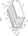
- Power supply device 100 according to a first exemplary embodiment of the present invention is shown in Figs. 1 to 2 .
- Fig. 1 is a perspective view of power supply device 100 according to the first exemplary embodiment
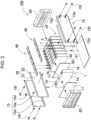
- Fig. 2 is an exploded perspective view of power supply device 100 shown in Fig. 1 .
- Power supply device 100 shown in these drawings includes battery stack 10 in which a plurality of battery cells 1 are stacked with insulating spacer 16 interposed therebetween, a pair of end plates 20 covering both end surfaces of battery stack 10, a plurality of fastening members 15 for fastening end plates 20 to each other, and bus bar 40 disposed on the upper surface of battery stack 10.
- Fastening members 15 are each formed into a plate shape extending in a stacking direction of the plurality of battery cells 1.
- Fastening members 15 are respectively disposed on opposite side surfaces of battery stack 10 and fasten end plates 20 to each other.
- battery stack 10 includes the plurality of battery cells 1 each including positive and negative electrode terminals 2, and bus bars 40 connected to electrode terminals 2 of the plurality of battery cells 1 to connect the plurality of battery cells 1 in parallel and in series.
- the plurality of battery cells 1 are connected in parallel or in series through bus bars 40.
- Battery cell 1 is a chargeable and dischargeable secondary battery.
- the plurality of battery cells 1 are connected in parallel to constitute a parallel battery group, and a plurality of the parallel battery groups are connected in series to allow a large number of battery cells 1 to be connected in parallel and in series.
- the plurality of battery cells 1 are stacked to form battery stack 10.
- a pair of end plates 20 are disposed on both end surfaces of battery stack 10. End parts of fastening members 15 are respectively fixed to end plates 20 to fix stacked battery cells 1 in a pressurized state.
- battery cell 1 is a prismatic parallelepiped battery whose width is larger than the thickness, in other words, whose thickness smaller than the width, and the battery cells 1 are stacked in the thickness to form battery stack 10.
- Battery cell 1 can be, for example, a lithium ion secondary battery.
- the battery cell can be any chargeable secondary battery such as a nickel metal hydride battery or a nickel cadmium battery.
- Battery cell 1 houses positive and negative electrode plates in outer covering can 1a having a sealed structure together with an electrolyte solution.
- Outer covering can 1a is obtained by press-molding a metal sheet such as aluminum or an aluminum alloy into a prismatic shape, and hermetically sealing an opening portion with sealing plate 1b.
- Sealing plate 1b is made of aluminum or aluminum alloy similarly as prismatic parallelepiped outer covering can 1a, and positive and negative electrode terminals 2 are respectively fixed to both end parts of sealing plate 1b. Sealing plate 1b is provided with, between positive and negative electrode terminals 2, gas discharge valve 1c, which is a safety valve that opens in response to an internal pressure change of each of battery cells 1.
- the plurality of battery cells 1 are stacked to allow the thickness of each battery cell 1 to be aligned with the stacking direction to constitute battery stack 10. At this time, by providing more stacks than usual, output power of battery stack 10 can be increased. In this case, battery stack 10 becomes long and extended in the stacking direction.
- Battery cells 1 are disposed to allow terminal surfaces 1X each provided with positive and negative electrode terminals 2 to be on the same plane, and the plurality of battery cells 1 are stacked to constitute battery stack 10.
- the upper surface of battery stack 10 is a surface provided with gas discharge valves 1c of the plurality of battery cells 1.
- Electrode terminal 2 includes a protrusion having a circular columnar shape.
- the protrusion is not necessarily in a circular columnar shape and may be in a polygonal columnar shape or an elliptic columnar shape.
- Positive and negative electrode terminals 2 fixed to sealing plate 1b of battery cell 1 are positioned where the positive electrode and the negative electrode are bilaterally symmetrical. This enables adjacent battery cells 1 to be connected in series by stacking battery cells 1 in an alternately and horizontally reversed manner and connecting electrode terminals 2 of the positive electrode and the negative electrode that are adjacent and close to each other by bus bars 40, as shown in Fig. 2 .
- the present invention does not specify the number and the connection state of the battery cells constituting the battery stack.
- the number and the connection state of the battery cells constituting the battery stack may be modified in various manners, inclusive of other exemplary embodiments described later.
- the plurality of battery cells 1 are stacked to allow the thickness of each battery cell 1 to be aligned with the stacking direction to constitute battery stack 10.
- the plurality of battery cells 1 are stacked to allow terminal surfaces 1X provided with positive and negative electrode terminals 2, or sealing plates 1b in Fig. 2 , to be flush with each other.
- adjacent electrode terminals 2 are coupled together with bus bars 40 made of metal sheets to connect battery cells 1 in series.
- bus bars 40 Both ends of bus bars 40 are respectively connected to positive and negative electrode terminals 2 so that bus bars 40 connect battery cells 1 in series or in parallel.
- output voltage can be increased by connecting battery cells 1 in series
- output voltage and output current can be increased by connecting battery cells 1 in parallel and in series.
- insulating spacer 16 is interposed between battery cells 1 stacked adjacent to each other.
- Insulating spacer 16 is made of insulating material such as resin in the form of a thin plate or sheet. Insulating spacer 16 is formed to have a plate shape that is substantially equal in size to the opposing surface of battery cell 1.
- This insulating spacer 16 can be stacked between battery cells 1 adjacent to each other to insulate adjacent battery cells 1 from each other.
- a spacer can be used which has a shape that allows a flow path through which a cooling gas flows to be formed between the battery cell and the spacer.
- the surface of the battery cell can be covered with an insulating material.
- the surface of the outer covering can except for the electrode terminal portion of the battery cell may be covered with a shrink film such as a polyethylene terephthalate (PET) resin.
- PET polyethylene terephthalate
- power supply device 100 shown in Fig. 2 includes end plates 20 respectively disposed on both end surfaces of battery stack 10. Between each of end plates 20 and battery stack 10, end surface spacer 17 may be interposed to insulate the two. End surface spacer 17 can also be formed in the form of a thin plate or sheet with insulating material such as resin.
- electrode terminals 2 of the plurality of battery cells 1 adjacent to each other are connected by bus bars 40 to connect the plurality of battery cells 1 in parallel and in series.
- end plates 20 are respectively disposed at both ends of battery stack 10 and fastened with each other through the pair of right and left fastening members 15 that are respectively disposed along both side surfaces of battery stack 10.
- End plates 20 are respectively disposed on the outer sides of end surface spacers 17, that is, both ends in the stacking direction of battery cells 1 of battery stack 10, and clamp battery stack 10 from both ends.
- fastening member 15 is fixed at both ends to end plates 20 respectively disposed on both end surfaces of battery stack 10. End plates 20 are fixed by the plurality of fastening members 15 to fasten battery stack 10 in the stacking direction. As shown in Fig. 2 and the like, fastening members 15 are each made of metal having a predetermined width and a predetermined thickness along the side surface of battery stack 10, and are disposed facing each other on both side surfaces of battery stack 10. A metal sheet of iron or the like, preferably a steel sheet, can be used as fastening member 15. Fastening member 15 made of a metal sheet is bent by press molding or the like to be formed into a predetermined shape.
- Fastening member 15 includes plate-shaped fastening main surface 15a whose upper and lower parts are bent in a U-shape to form bent pieces 15d. Upper and lower bent pieces 15d respectively cover upper and lower surfaces of battery stack 10 from the corners on the left and right side surfaces of battery stack 10.
- Power supply device 100 having a large number of battery cells 1 stacked is configured such that the plurality of battery cells 1 are constrained by connecting end plates 20 respectively disposed at both ends of battery stack 10 including the plurality of battery cells 1 using fastening members 15.
- end plates 20 and fastening members 15 that have high rigidity, malfunction or other faults caused by swelling, deformation, relative displacement, or vibration of battery cells 1 due to charging and discharging or degradation can be suppressed.
- Insulating sheet 30 is interposed between fastening member 15 and battery stack 10.
- Insulating sheet 30 is made of material having an insulating property, such as resin, and insulates metal fastening member 15 from battery cell 1.
- Insulating sheet 30 shown in Fig. 2 and the like is constituted of flat plate 31 for covering the side surface of battery stack 10, and bent covers 32 respectively provided on an upper part and a lower part of flat plate 31. Bent covers 32 are formed by being bent in a U shape from flat plate 31 so as to respectively cover bent pieces 15d of fastening member 15, and then by further being folded back. As a result, bent pieces 15d are covered with the insulating bent covers from the upper surface to the side surface and the lower surface, which can avoid unintended conduction between battery cell 1 and fastening member 15.
- Bent pieces 15d press the upper surface and the lower surface of battery cells 1 of battery stack 10 through bent covers 32. As a result, each battery cell 1 is pressed by bent pieces 15d from the upper and lower sides to be held in the height direction, and even when vibration, impact, or the like is applied to battery stack 10, each battery cell 1 can be maintained so as not to be displaced in the vertical direction.
- the insulating sheet is unnecessary in the case where the battery stack or the surface of the battery stack is insulated, for example, in the case where the battery cell is housed in an insulating case or covered with a heat-shrinkable film made of resin, or in the case where an insulating paint or coating is applied to the surface of the fastening member, or in the case where the fastening member is made of an insulating material.
- bent cover 32 may be provided only near the upper end in the case where insulation from bent piece 15d of fastening member 15 does not need to be taken into consideration near the lower surface of battery stack 10. This corresponds to, for example, the case where the battery cell is covered with a heat-shrinkable film.
- end plate 20 Details of end plate 20 are described with reference to Figs. 3 to 4 .
- Fig. 3 is an enlarged perspective view of a portion of end plate 20 of power supply device 100 in Fig. 1
- Fig. 4 is a longitudinal sectional view of a portion of end plate 20 of power supply device 100 in Fig. 1 .
- End plate 20 in these drawings has frame shape 21 in which the periphery protrudes while the outer shape in plan view is a rectangular shape.
- a rectangular region surrounded by frame shape 21 is used as a pressing surface that covers an end surface of battery stack 10.
- a screw hole or a cutout for connecting to another portion may be disposed near the upper surface of frame shape 21, as necessary. Further, end plate 20 is disposed with pressing regions 25 respectively near end edge in the up-down direction of the pressing surface, and is disposed with bead region 26 between pressing regions 25.
- Each of upper and lower pressing regions 25 has a flat surface, and presses battery stack 10.
- the widths of upper and lower pressing regions 25 are substantially equal to each other.
- Pressing regions 25 including bead region 26 is preferably is disposed in line-symmetry in the horizontal direction.
- bead region 26 is formed in the middle in the vertical direction of the pressing surface, and is bent into a shape protruding toward the back surface of the pressing surface.
- the strength can be improved by changing a shape in which bead region 26 is disposed in the middle while pressing regions 25 that press battery stack 10 remain on end plate 20, which enables end plate 20 having high strength to be provided at low cost.
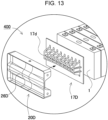
- end plate 20 including bead region 26 has a shape having a space near battery cell 1. Therefore, as in power supply device 400 according to a fourth exemplary embodiment shown in Fig. 13 , end surface spacer 17D is preferably disposed between battery cell 1 and end plate 20D. Specifically, as shown in Fig. 13 , end surface spacer 17D has protrusion 17d that protrudes toward the recess (the back surface of bead region 26D) of end plate 20D to allow battery cell 1 and end plate 20D to transfer the force therebetween over the entire surface.
- end plate 20 is disposed with frame shape 21 around the pressing surface.
- frame shape 21 both sides of the side surface of the pressing surface are side walls 22.
- Side wall 22 is disposed with fixing regions 23 for fixing end plate 20 to fastening member 15 respectively at positions corresponding to pressing regions 25 on the vertical end edge.
- Fixing regions 23 are disposed in the same plane on the upper and lower sides.
- each of fixing regions 23 is a flat surface.
- End plate 20 is fixed to fastening member 15 by fixing regions 23.
- End plate 20 and fastening member 15 are preferably fixed by welding or caulking. For example, spot welding, clinching, or the like can be used. In addition, screwing using a bolt or the like may be employed.
- Side wall 22 is connected to the protruding shape of bead region 26 between these fixing regions 23, that is, at a central portion in the up-down direction.
- fixing region 23 connected to fastening member 15 is not provided in the middle of side wall 22 in the height.
- fixing regions 23 for fixing end plate 20 to fastening member 15 are secured in the upper and lower parts of side wall 22 to establish a fixing structure for fixing end plate 20 to fastening member 15.
- the protruding shape of bead region 26 is preferably formed in a curved surface shape as shown in the schematic cross-sectional view in Fig. 5A .
- concentration of stress can be avoided more compared to end plate 20X having a configuration in which bead region 26X is bent in a U shape as shown in Fig. 5B , and the strength of end plate 20 can be improved by dispersing the stress.
- Side wall 22 of end plate 20 is preferably disposed continuously with bead region 26 at the center in the vertical direction with a curved surface. As a result, the strength can be secured by making the central portion continuous with the protruding portion of bead region 26 while securing the region where end plate 20 is coupled to fastening member 15 on side wall 22 of end plate 20.
- the protruding shape of bead region 26 be shaped to protrude relatively steeply in the central portion in the left and right direction in vertical sectional view as shown in Fig. 6A , but meanwhile, be shaped to gradually incline towards both sides as shown in Fig. 6B . In this way, in the middle of the pressing surface in the left and right direction where the strength becomes relatively weak, the protruding shape is tightened to increase the strength, and the end part of the pressing surface can be deformed to secure fixing region 23 for fixing fastening member 15 to side wall 22 of end plate 20.
- end plate 20 is preferably slightly inclined in the protruding direction of side wall 22, that is, in the direction toward the back surface of the pressing surface at the boundary with side wall 22 as shown in Fig. 3 .
- End plate 20 thus configured can be formed by bending one metal sheet by press working. As a result, the required strength can be maintained only with one sheet and without using two sheets of sheet metal as in the conventional end plate, and further, cost and weight can be reduced. End plate 20 is preferably formed by processing a sheet metal such as stainless steel (SUS) or a high tensile strength steel sheet.
- SUS stainless steel
- end plate 20 having this configuration does not require the size of the power supply device to be increased in order to avoid interference between a fixing processing facility such as a mechanical clinch and the power supply device as in the conventional case.
- end plate 20 is preferably designed such that the sum of the heights of pressing regions 25 formed in the upper and lower parts is substantially equal to the height of bead region 26 formed in the middle in cross-sectional view.
- Fig. 4 which is a longitudinal sectional view in the middle in the width direction of end plate 20
- fixing regions 23B can be provided not only at the upper and lower end edges but also in the middle, the reliability of fixing end plate 20B to fastening member 15 can be improved.
- the members similar to those described in the above first exemplary embodiment are denoted by the same reference numerals, and detailed description thereof are appropriately omitted.
- the end plate is bent to provide the bead region, and the pressing surface of the end plate is pressed against and fastened to the battery stack.
- the present invention is not limited to the example in which the bead region of the end plate is a cavity, and the bead region may be solid.
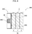
- An example of this is shown as power supply device 300 according to a third exemplary embodiment in a schematic cross-sectional view in Fig. 8 . Note that also in power supply device 300 according to the third exemplary embodiment, the members similar to those described in the above first exemplary embodiment are denoted by the same reference numerals, and detailed description thereof are appropriately omitted.
- End plate 20C shown in Fig. 8 includes the pressing surface that is not hollow but solid.
- bead region 26 of end plate 20C is filled with insulating member 28 such as resin or rubber.
- Insulating member 28 may be configured to cover not only bead region 26C but also pressing region 25C.
- the pressing surface that presses battery stack 10 is made of a uniform material, which allows the end surface of battery stack 10 to be uniformly pressed and the heat to be uniformly dissipated.
- insulating member 28 as compared with the configuration in Fig. 4 and the like partially including an air layer, the air layer can be eliminated and the heat dissipation property of the end surface of battery stack 10 can be improved.
- a thermal coupling state with the end surface of battery stack 10 can be made uniform and heat dissipation performance can be uniformly exerted.
- power supply device 100 can be used as a power supply for a vehicle where electric power is supplied to a motor used for causing an electrically-driven vehicle to travel.
- an electrically-driven vehicle equipped with power supply device 100 an electrically-driven vehicle such as a hybrid automobile or a plug-in hybrid automobile that travels with both an engine and a motor, or an electric automobile that travels only with a motor can be used, and the power supply device is used as a power supply for these vehicles.
- a large-capacity, high-output power supply device in which a large number of power supply devices 100 described above are connected in series or in parallel to obtain electric power for driving an electrically-driven vehicle and a necessary controlling circuit is further added is constructed.
- Fig. 9 shows an example in which power supply device 100 is mounted on a hybrid automobile that travels by both an engine and a motor.
- Vehicle HV on which power supply device 100 shown in this drawing is mounted includes vehicle body 91, engine 96 and drive motor 93 that cause vehicle body 91 to travel, wheels 97 that are driven by engine 96 and drive motor 93, power supply device 100 that supplies electric power to motor 93, and power generator 94 that charges a battery of power supply device 100.
- Power supply device 100 is connected to motor 93 and power generator 94 via DC/AC inverter 95. Vehicle HV travels using both motor 93 and engine 96 while charging and discharging the battery of power supply device 100.
- Motor 93 is driven in a region where an engine efficiency is low, for example, during acceleration or low-speed traveling, and causes the vehicle to travel. Motor 93 is driven by electric power supplied from power supply device 100. Power generator 94 is driven by engine 96 or by regenerative braking generated at the time of applying braking to the vehicle, and charges the battery of power supply device 100. As shown in Fig. 9 , vehicle HV may include charging plug 98 for charging power supply device 100. By connecting charging plug 98 to an external power supply, power supply device 100 can be charged.
- Fig. 10 shows an example in which power supply device 100 is mounted on an electric automobile that travels only by a motor.
- Vehicle EV on which power supply device 100 shown in this drawing is mounted includes vehicle body 91, drive motor 93 that causes vehicle body 91 to travel, wheels 97 that are driven by motor 93, power supply device 100 that supplies electric power to motor 93, and power generator 94 that charges a battery of power supply device 100.
- Power supply device 100 is connected to motor 93 and power generator 94 via DC/AC inverter 95.
- Motor 93 is driven by electric power supplied from power supply device 100.
- Power generator 94 is driven by the energy at the time of applying regenerative braking to vehicle EV and charges the battery of power supply device 100.
- Vehicle EV also includes charging plug 98, and power supply device 100 can be charged by connecting charging plug 98 to an external power supply.
- the present invention does not limit the application of the power supply device to a power supply for a motor that causes a vehicle to travel.
- the power supply device according to the exemplary embodiment can be used also as a power supply for a power storage device that charges a battery with electric power generated by photovoltaic power generation, wind power generation, or the like, and stores electricity.
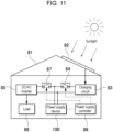
- Fig. 11 shows a power storage device that charges a battery of power supply device 100 with solar battery 82 and stores electricity.
- the power storage device shown in Fig. 11 charges the battery of power supply device 100 with electric power generated by solar battery 82 arranged on a roof, a rooftop, or the like of building 81 such as a house or a factory.
- the battery of power supply device 100 is charged by charging circuit 83 using solar battery 82 as a charging power supply, and thereafter, electric power is supplied to load 86 via DC/AC inverter 85.
- this power storage device includes a charge mode and a discharge mode.
- DC/AC inverter 85 is connected to power supply device 100 via discharging switch 87 and charging circuit 83 is connected to power supply device 100 via charging switch 84.
- Discharging switch 87 and charging switch 84 are turned on and off by power supply controller 88 of the power storage device.
- power supply controller 88 turns on charging switch 84 and turns off discharging switch 87 to allow charging from charging circuit 83 to power supply device 100.
- power supply controller 88 turns off charging switch 84 and turns on discharging switch 87 to switch the mode to the discharge mode and allows discharging from power supply device 100 to load 86.
- the power supply controller can turn on charging switch 84 and turn on discharging switch 87 to supply electricity to load 86 and charge power supply device 100 simultaneously.
- the power supply device can be used as a power supply for a power storage device that stores electricity by charging a battery using midnight electric power at nighttime.
- the power supply device that is to be charged with midnight electric power is charged with midnight electric power that is surplus electric power generated by a power station, and outputs the electric power during the daytime when an electric power load increases. This can limit peak electric power during the daytime to a small value.
- the power supply device can also be used as a power supply charged with both output of a solar battery and midnight electric power. This power supply device can effectively utilize both electric power generated by the solar battery and the midnight electric power, and can efficiently store power in consideration of weather and power consumption.
- the power storage system as described above can be suitably used in applications such as a backup power supply device that can be installed in a computer server rack, a backup power supply device for radio base stations for cellular phones and the like, a power storage device combined with a solar battery such as a power storage power supply for homes and factories or a power supply for street lights, and a backup power supply for traffic lights and traffic indicators on roads.
- a backup power supply device that can be installed in a computer server rack
- a power storage device combined with a solar battery such as a power storage power supply for homes and factories or a power supply for street lights
- a backup power supply for traffic lights and traffic indicators on roads such as a backup power supply device that can be installed in a computer server rack, a backup power supply device for radio base stations for cellular phones and the like, a power storage device combined with a solar battery such as a power storage power supply for homes and factories or a power supply for street lights, and a
- the power supply device can be suitably used as a power supply for a large current, which is used for a power supply of a motor for driving an electrically-driven vehicle such as a hybrid automobile, a fuel cell automobile, an electric automobile, or an electric motorcycle.
- the power supply device include a power supply device for a plug-in hybrid electric automobile and a hybrid electric automobile that can switch between an EV traveling mode and an HEV traveling mode, an electric automobile, or the like.
- the power supply device can also be appropriately used for the applications including a backup power supply device that can be mounted on a computer sever rack, a backup power supply device for radio base stations of cellular phones and the like, a power storage device combined with a solar battery such as a power storage power supply for homes and factories or a power supply for street lights, and a backup power supply for traffic lights.
Landscapes
- Chemical & Material Sciences (AREA)
- Chemical Kinetics & Catalysis (AREA)
- Electrochemistry (AREA)
- General Chemical & Material Sciences (AREA)
- Engineering & Computer Science (AREA)
- Mechanical Engineering (AREA)
- Transportation (AREA)
- Aviation & Aerospace Engineering (AREA)
- Inorganic Chemistry (AREA)
- Manufacturing & Machinery (AREA)
- Life Sciences & Earth Sciences (AREA)
- Sustainable Development (AREA)
- Sustainable Energy (AREA)
- Power Engineering (AREA)
- Combustion & Propulsion (AREA)
- Battery Mounting, Suspending (AREA)
- Electric Propulsion And Braking For Vehicles (AREA)
Abstract
Description
- The present disclosure relates to a power supply device, a vehicle provided with the same, and a power storage device.
- A power supply device such as a battery module or a battery pack including a plurality of battery cells is used as a power supply for vehicle such as a hybrid automobile or an electric automobile, and a power supply of a power storage system for factory, home, and others.
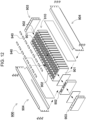
- In such a power supply device, a plurality of chargeable and rechargeable battery cells are stacked. For example, as shown in a schematic perspective view in
Fig. 12 ,power supply device 900 is configured bystacking battery cells 901 each formed as prismatic parallelepiped outer covering can to obtainbattery stack 910, disposingend plates 903 respectively on both end surfaces ofbattery stack 910, and fasteningend plates 903 to each other withbind bars 904.Battery cell 901 having a square shape is provided with, on the upper surface, positive andnegative electrode terminals 902 separated from each other.Electrode terminals 902 ofadjacent battery cells 901 are connected bybus bar 940. - In this structure in which the battery stack is pressed and fastened by the end plates, the end plates need to have sufficient strength. Generally, increasing the strength of the end plates increases the cost. For example, the end plates using two sheet metals for securing strength are expensive. In addition, in the case where a mechanical clinch is used for fixing the end plates and the bind bars to each other (see Patent Literature 1), the mechanical clinch has a large equipment size, and interference at the time of processing needs to be avoided on the power supply device, and as a result, a problem has occurred that the size of the power supply device increases.
- PTL 1: Unexamined
Japanese Patent Publication No. 2013-69657 - An object of one aspect of the present invention is to provide a power supply device that achieves cost reduction while maintaining strength of an end plate, a vehicle provided with the power supply device, and a power storage device.
- A power supply device according to an aspect of the present invention includes: a battery stack including battery cells of a prismatic shape stacked in plural numbers; an end plate of a rectangular shape in plan view, the end plate including a pressing surface covering an end surface of the battery stack; and a fastening member that fastens the battery stack, in which the end plate includes, on the pressing surface, pressing regions of a flat shape respectively disposed closer to end edge in the vertical direction, and a bead region disposed closer to the middle in the vertical direction and bent into a shape protruding toward a back surface side of the pressing surface.
- According to the power supply device according to one aspect of the present invention, because the strength can be improved by changing a shape in which the bead region is disposed in the middle while the pressing region that presses the battery stack remains on the end plate, the end plate having high strength can be provided at low cost.
-
-
Fig. 1 is a perspective view showing a power supply device according to a first exemplary embodiment of the present invention. -
Fig. 2 is an exploded perspective view of the power supply device shown inFig. 1 . -
Fig. 3 is an enlarged perspective view of a portion of an end plate of the power supply device inFig. 1 . -
Fig. 4 is a longitudinal sectional view of the end plate of the power supply device inFig. 1 . -
Fig. 5A is a schematic longitudinal sectional view of the end plate in which a bead region is a curved surface shape, andFig. 5B is a schematic cross-sectional view of the end plate in which the bead region is a U shape. -
Fig. 6A is a schematic longitudinal sectional view taken along a line VIA-VIA inFig. 3 , andFig. 6B is a schematic longitudinal sectional view taken along a line VIB-VIB inFig. 3 . -
Fig. 7 is a longitudinal sectional view of an end plate of a power supply device according to a second exemplary embodiment. -
Fig. 8 is a longitudinal sectional view of an end plate of a power supply device according to a third exemplary embodiment. -
Fig. 9 is a block diagram showing an example in which the power supply device is mounted on a hybrid automobile that travels by an engine and a motor. -
Fig. 10 is a block diagram showing an example in which the power supply device is mounted on an electric automobile that travels only by a motor. -
Fig. 11 is a block diagram showing an example of applying the power supply device to a power supply device for power storage. -
Fig. 12 is an exploded perspective view showing the conventional power supply device. -
Fig. 13 is an exploded perspective view of a portion of an end plate of a power supply device according to a fourth exemplary embodiment. - Exemplary embodiments of the present invention may be specified by the following configurations.
- In the power supply device according to one exemplary embodiment of the present invention, in addition to the above configuration, the end plate is provided with side walls respectively on both side surfaces of the pressing surface, and the side walls each include fixing regions configured to be fixed with the fastening member at positions corresponding to the pressing regions closer to end edge in the vertical direction, the side wall being connected to a protruding shape of the bead region at a central portion in the vertical direction. With the above configuration, the strength can be secured by making the central portion continuous with the protruding shape of the bead region while securing the fixing region where the end plate is coupled to the fastening members on both side surfaces of the end plate.
- In the power supply device according to another exemplary embodiment of the present invention, in addition to any of the above configurations, in the end plate, the protruding shape of the bead region is a curved shape. With the above configuration, concentration of stress can be avoided more as compared to a configuration in which the bead region is bent in a U shape, and the strength of the end plate can be improved by dispersing the stress.
- In addition, in the power supply device according to another exemplary embodiment of the present invention, in addition to any of the above configurations, the side wall of the end plate is continuous in a curved surface at a central portion with the bead region. With the above configuration, the strength can be secured by making the central portion continuous with the protruding portion of the bead region while securing the region where the end plate is coupled to the fastening member on the side wall of the end plate.
- Further, in the power supply device according to another exemplary embodiment of the present invention, in addition to any one of the above configurations, in the end plate, the protruding shape of the bead region is protruded steeply at left and right central portions in vertical sectional view and is inclined gently toward both sides. With the above configuration, the central portion of the end plate is brought close to the protruding strip to improve the strength, and meanwhile, the fixing portion with the fastening member is secured by the side wall of the end plate at the end part.
- Still further, in the power supply device according to another exemplary embodiment of the present invention, in addition to any of the above configurations, the end plate is one metal sheet bent by press working. With the above configuration, the end plate can be reduced in cost and weight.
- Furthermore, in the power supply device according to another exemplary embodiment of the present invention, in addition to any of the configurations described above, in cross-sectional view, the end plate includes the pressing regions respectively disposed in upper and lower parts of the end plate and whose heights sum up to a height of the bead region disposed in a middle. With the above configuration, both pressing force and rigidity of the end plate can be achieved in a well-balanced manner.
- Furthermore, in the power supply device according to another exemplary embodiment of the present invention, in addition to any of the above configurations, the end plate is fixed to the fastening member by welding or caulking. With the above configuration, the strength can be secured while securing the fixing portion between the end plate and the fastening member.
- An electrically-driven vehicle according to another exemplary embodiment of the present invention includes any of the above power supply devices, a motor for driving supplied with electric power from the power supply device, a vehicle body equipped with the power supply device and the motor, and wheels driven by the motor to cause the vehicle body to travel.
- Further, a power storage device according to another exemplary embodiment of the present invention includes any of the above power supply devices and a power supply controller that controls charging and discharging of the power supply device, the power supply controller enabling charging of the battery cells with electric power from outside and controlling charging to be performed on the battery cells.
- Hereinafter, exemplary embodiments of the present invention are described with reference to the drawings. However, the exemplary embodiments described below are examples for embodying the technical idea of the present invention, and the present invention is not limited to the following. In the present description, members indicated in the claims are not limited to the members of the exemplary embodiments. In particular, dimensions, materials, shapes, and relative arrangement of the constituent members described in the exemplary embodiments are not intended to limit the scope of the present invention only thereto unless otherwise specified and are merely illustrative examples. Note that sizes, positional relationships, and others of the members shown in the drawings may be exaggerated to clarity the description. In the following description, the same names and reference marks indicate the same or similar members, and detailed descriptions are appropriately omitted. The elements constituting the present invention may be configured such that the plurality of elements are constituted of the same members to form one member that functions as a plurality of elements, or conversely, the function of one member can be shared and achieved by a plurality of members. Contents described in some examples or exemplary embodiments can be used, for example, in other examples or exemplary embodiments.
- The power supply device according to the exemplary embodiments can be used in various applications including a power supply that is mounted in an electrically-driven vehicle such as a hybrid automobile and an electric automobile to supply electric power to a drive motor, a power supply that stores power generated by natural energy such as photovoltaic power generation and wind power generation, and a power supply for storing late-night power, and in particular, the power supply device can be used as a power supply suitable for high power and high current applications. In the following example, the exemplary embodiments applied to a power supply device for driving an electrically-driven vehicle is described.
-
Power supply device 100 according to a first exemplary embodiment of the present invention is shown inFigs. 1 to 2 . In these drawings,Fig. 1 is a perspective view ofpower supply device 100 according to the first exemplary embodiment, andFig. 2 is an exploded perspective view ofpower supply device 100 shown inFig. 1 .Power supply device 100 shown in these drawings includesbattery stack 10 in which a plurality ofbattery cells 1 are stacked with insulatingspacer 16 interposed therebetween, a pair ofend plates 20 covering both end surfaces ofbattery stack 10, a plurality offastening members 15 for fasteningend plates 20 to each other, andbus bar 40 disposed on the upper surface ofbattery stack 10. Fasteningmembers 15 are each formed into a plate shape extending in a stacking direction of the plurality ofbattery cells 1. Fasteningmembers 15 are respectively disposed on opposite side surfaces ofbattery stack 10 and fastenend plates 20 to each other. - As shown in
Fig. 2 ,battery stack 10 includes the plurality ofbattery cells 1 each including positive andnegative electrode terminals 2, andbus bars 40 connected toelectrode terminals 2 of the plurality ofbattery cells 1 to connect the plurality ofbattery cells 1 in parallel and in series. The plurality ofbattery cells 1 are connected in parallel or in series through bus bars 40.Battery cell 1 is a chargeable and dischargeable secondary battery. Inpower supply device 100, the plurality ofbattery cells 1 are connected in parallel to constitute a parallel battery group, and a plurality of the parallel battery groups are connected in series to allow a large number ofbattery cells 1 to be connected in parallel and in series. Inpower supply device 100 shown inFig. 2 , the plurality ofbattery cells 1 are stacked to formbattery stack 10. A pair ofend plates 20 are disposed on both end surfaces ofbattery stack 10. End parts offastening members 15 are respectively fixed toend plates 20 to fix stackedbattery cells 1 in a pressurized state. - As shown in
Fig. 2 ,battery cell 1 is a prismatic parallelepiped battery whose width is larger than the thickness, in other words, whose thickness smaller than the width, and thebattery cells 1 are stacked in the thickness to formbattery stack 10.Battery cell 1 can be, for example, a lithium ion secondary battery. The battery cell can be any chargeable secondary battery such as a nickel metal hydride battery or a nickel cadmium battery.Battery cell 1 houses positive and negative electrode plates in outer covering can 1a having a sealed structure together with an electrolyte solution. Outer covering can 1a is obtained by press-molding a metal sheet such as aluminum or an aluminum alloy into a prismatic shape, and hermetically sealing an opening portion with sealing plate 1b. Sealing plate 1b is made of aluminum or aluminum alloy similarly as prismatic parallelepiped outer covering can 1a, and positive andnegative electrode terminals 2 are respectively fixed to both end parts of sealing plate 1b. Sealing plate 1b is provided with, between positive andnegative electrode terminals 2, gas discharge valve 1c, which is a safety valve that opens in response to an internal pressure change of each ofbattery cells 1. - The plurality of
battery cells 1 are stacked to allow the thickness of eachbattery cell 1 to be aligned with the stacking direction to constitutebattery stack 10. At this time, by providing more stacks than usual, output power ofbattery stack 10 can be increased. In this case,battery stack 10 becomes long and extended in the stacking direction.Battery cells 1 are disposed to allowterminal surfaces 1X each provided with positive andnegative electrode terminals 2 to be on the same plane, and the plurality ofbattery cells 1 are stacked to constitutebattery stack 10. The upper surface ofbattery stack 10 is a surface provided with gas discharge valves 1c of the plurality ofbattery cells 1. - In
battery cell 1, as shown inFig. 2 and the like, sealing plate 1b being a top surface serves asterminal surface 1X, and positive andnegative electrode terminals 2 are fixed to both ends ofterminal surface 1X.Electrode terminal 2 includes a protrusion having a circular columnar shape. However, the protrusion is not necessarily in a circular columnar shape and may be in a polygonal columnar shape or an elliptic columnar shape. - Positive and
negative electrode terminals 2 fixed to sealing plate 1b ofbattery cell 1 are positioned where the positive electrode and the negative electrode are bilaterally symmetrical. This enablesadjacent battery cells 1 to be connected in series by stackingbattery cells 1 in an alternately and horizontally reversed manner and connectingelectrode terminals 2 of the positive electrode and the negative electrode that are adjacent and close to each other bybus bars 40, as shown inFig. 2 . Note that the present invention does not specify the number and the connection state of the battery cells constituting the battery stack. The number and the connection state of the battery cells constituting the battery stack may be modified in various manners, inclusive of other exemplary embodiments described later. - The plurality of
battery cells 1 are stacked to allow the thickness of eachbattery cell 1 to be aligned with the stacking direction to constitutebattery stack 10. Inbattery stack 10, the plurality ofbattery cells 1 are stacked to allowterminal surfaces 1X provided with positive andnegative electrode terminals 2, or sealing plates 1b inFig. 2 , to be flush with each other. Inbattery stack 10,adjacent electrode terminals 2 are coupled together withbus bars 40 made of metal sheets to connectbattery cells 1 in series. - Both ends of
bus bars 40 are respectively connected to positive andnegative electrode terminals 2 so that bus bars 40 connectbattery cells 1 in series or in parallel. Inpower supply device 100, output voltage can be increased by connectingbattery cells 1 in series, and output voltage and output current can be increased by connectingbattery cells 1 in parallel and in series. - In
battery stack 10, insulatingspacer 16 is interposed betweenbattery cells 1 stacked adjacent to each other. Insulatingspacer 16 is made of insulating material such as resin in the form of a thin plate or sheet. Insulatingspacer 16 is formed to have a plate shape that is substantially equal in size to the opposing surface ofbattery cell 1. This insulatingspacer 16 can be stacked betweenbattery cells 1 adjacent to each other to insulateadjacent battery cells 1 from each other. As a spacer disposed between the adjacent battery cells, a spacer can be used which has a shape that allows a flow path through which a cooling gas flows to be formed between the battery cell and the spacer. In addition, the surface of the battery cell can be covered with an insulating material. For example, the surface of the outer covering can except for the electrode terminal portion of the battery cell may be covered with a shrink film such as a polyethylene terephthalate (PET) resin. - Further,
power supply device 100 shown inFig. 2 includesend plates 20 respectively disposed on both end surfaces ofbattery stack 10. Between each ofend plates 20 andbattery stack 10,end surface spacer 17 may be interposed to insulate the two.End surface spacer 17 can also be formed in the form of a thin plate or sheet with insulating material such as resin. - In
power supply device 100 according to the first exemplary embodiment, inbattery stack 10 in which the plurality ofbattery cells 1 are stacked on each other,electrode terminals 2 of the plurality ofbattery cells 1 adjacent to each other are connected bybus bars 40 to connect the plurality ofbattery cells 1 in parallel and in series. - As shown in
Fig. 2 ,end plates 20 are respectively disposed at both ends ofbattery stack 10 and fastened with each other through the pair of right and leftfastening members 15 that are respectively disposed along both side surfaces ofbattery stack 10.End plates 20 are respectively disposed on the outer sides ofend surface spacers 17, that is, both ends in the stacking direction ofbattery cells 1 ofbattery stack 10, and clampbattery stack 10 from both ends. - Each of fastening
member 15 is fixed at both ends to endplates 20 respectively disposed on both end surfaces ofbattery stack 10.End plates 20 are fixed by the plurality offastening members 15 to fastenbattery stack 10 in the stacking direction. As shown inFig. 2 and the like,fastening members 15 are each made of metal having a predetermined width and a predetermined thickness along the side surface ofbattery stack 10, and are disposed facing each other on both side surfaces ofbattery stack 10. A metal sheet of iron or the like, preferably a steel sheet, can be used as fasteningmember 15. Fasteningmember 15 made of a metal sheet is bent by press molding or the like to be formed into a predetermined shape. - Fastening
member 15 includes plate-shaped fasteningmain surface 15a whose upper and lower parts are bent in a U-shape to formbent pieces 15d. Upper and lowerbent pieces 15d respectively cover upper and lower surfaces ofbattery stack 10 from the corners on the left and right side surfaces ofbattery stack 10. -
Power supply device 100 having a large number ofbattery cells 1 stacked is configured such that the plurality ofbattery cells 1 are constrained by connectingend plates 20 respectively disposed at both ends ofbattery stack 10 including the plurality ofbattery cells 1 usingfastening members 15. By constraining the plurality ofbattery cells 1 throughend plates 20 andfastening members 15 that have high rigidity, malfunction or other faults caused by swelling, deformation, relative displacement, or vibration ofbattery cells 1 due to charging and discharging or degradation can be suppressed. - Insulating
sheet 30 is interposed betweenfastening member 15 andbattery stack 10. Insulatingsheet 30 is made of material having an insulating property, such as resin, and insulatesmetal fastening member 15 frombattery cell 1. Insulatingsheet 30 shown inFig. 2 and the like is constituted offlat plate 31 for covering the side surface ofbattery stack 10, and bent covers 32 respectively provided on an upper part and a lower part offlat plate 31. Bent covers 32 are formed by being bent in a U shape fromflat plate 31 so as to respectively coverbent pieces 15d of fasteningmember 15, and then by further being folded back. As a result,bent pieces 15d are covered with the insulating bent covers from the upper surface to the side surface and the lower surface, which can avoid unintended conduction betweenbattery cell 1 andfastening member 15. -
Bent pieces 15d press the upper surface and the lower surface ofbattery cells 1 ofbattery stack 10 through bent covers 32. As a result, eachbattery cell 1 is pressed bybent pieces 15d from the upper and lower sides to be held in the height direction, and even when vibration, impact, or the like is applied tobattery stack 10, eachbattery cell 1 can be maintained so as not to be displaced in the vertical direction. - Note that the insulating sheet is unnecessary in the case where the battery stack or the surface of the battery stack is insulated, for example, in the case where the battery cell is housed in an insulating case or covered with a heat-shrinkable film made of resin, or in the case where an insulating paint or coating is applied to the surface of the fastening member, or in the case where the fastening member is made of an insulating material. In addition, regarding insulating
sheet 30,bent cover 32 may be provided only near the upper end in the case where insulation frombent piece 15d of fasteningmember 15 does not need to be taken into consideration near the lower surface ofbattery stack 10. This corresponds to, for example, the case where the battery cell is covered with a heat-shrinkable film. - Details of
end plate 20 are described with reference toFigs. 3 to 4 . In these drawings,Fig. 3 is an enlarged perspective view of a portion ofend plate 20 ofpower supply device 100 inFig. 1 , andFig. 4 is a longitudinal sectional view of a portion ofend plate 20 ofpower supply device 100 inFig. 1 .End plate 20 in these drawings hasframe shape 21 in which the periphery protrudes while the outer shape in plan view is a rectangular shape. A rectangular region surrounded byframe shape 21 is used as a pressing surface that covers an end surface ofbattery stack 10. By forming the box shape in whichframe shape 21 is disposed around the pressing surface in this manner, the strength of the pressing surface can be increased. A screw hole or a cutout for connecting to another portion may be disposed near the upper surface offrame shape 21, as necessary. Further,end plate 20 is disposed withpressing regions 25 respectively near end edge in the up-down direction of the pressing surface, and is disposed withbead region 26 betweenpressing regions 25. - Each of upper and lower
pressing regions 25 has a flat surface, and pressesbattery stack 10. Preferably, the widths of upper and lowerpressing regions 25 are substantially equal to each other. Pressingregions 25 includingbead region 26 is preferably is disposed in line-symmetry in the horizontal direction. - Meanwhile,
bead region 26 is formed in the middle in the vertical direction of the pressing surface, and is bent into a shape protruding toward the back surface of the pressing surface. With this configuration, the strength can be improved by changing a shape in whichbead region 26 is disposed in the middle while pressingregions 25 that pressbattery stack 10 remain onend plate 20, which enablesend plate 20 having high strength to be provided at low cost. - In the case of molding
end plate 20 with sheet metal,end plate 20 includingbead region 26 has a shape having a space nearbattery cell 1. Therefore, as inpower supply device 400 according to a fourth exemplary embodiment shown inFig. 13 ,end surface spacer 17D is preferably disposed betweenbattery cell 1 andend plate 20D. Specifically, as shown inFig. 13 ,end surface spacer 17D hasprotrusion 17d that protrudes toward the recess (the back surface ofbead region 26D) ofend plate 20D to allowbattery cell 1 andend plate 20D to transfer the force therebetween over the entire surface. - Meanwhile,
end plate 20 is disposed withframe shape 21 around the pressing surface. Inframe shape 21, both sides of the side surface of the pressing surface areside walls 22.Side wall 22 is disposed with fixingregions 23 for fixingend plate 20 to fasteningmember 15 respectively at positions corresponding topressing regions 25 on the vertical end edge. Fixingregions 23 are disposed in the same plane on the upper and lower sides. In addition, each of fixingregions 23 is a flat surface.End plate 20 is fixed to fasteningmember 15 by fixingregions 23.End plate 20 andfastening member 15 are preferably fixed by welding or caulking. For example, spot welding, clinching, or the like can be used. In addition, screwing using a bolt or the like may be employed. -
Side wall 22 is connected to the protruding shape ofbead region 26 between these fixingregions 23, that is, at a central portion in the up-down direction. In other words, fixingregion 23 connected to fasteningmember 15 is not provided in the middle ofside wall 22 in the height. In this manner, by penetratingbead region 26 so as to cross the pressing surface in the horizontal direction as shown inFig. 3 and the like, the protruding shape ofbead region 26 is maintained and the reinforcing structure ofend plate 20 is exhibited. Meanwhile, fixingregions 23 for fixingend plate 20 to fasteningmember 15 are secured in the upper and lower parts ofside wall 22 to establish a fixing structure for fixingend plate 20 to fasteningmember 15. - The protruding shape of
bead region 26 is preferably formed in a curved surface shape as shown in the schematic cross-sectional view inFig. 5A . As a result, the concentration of stress can be avoided more compared toend plate 20X having a configuration in whichbead region 26X is bent in a U shape as shown inFig. 5B , and the strength ofend plate 20 can be improved by dispersing the stress. -
Side wall 22 ofend plate 20 is preferably disposed continuously withbead region 26 at the center in the vertical direction with a curved surface. As a result, the strength can be secured by making the central portion continuous with the protruding portion ofbead region 26 while securing the region whereend plate 20 is coupled to fasteningmember 15 onside wall 22 ofend plate 20. - Further, it is preferable that the protruding shape of
bead region 26 be shaped to protrude relatively steeply in the central portion in the left and right direction in vertical sectional view as shown inFig. 6A , but meanwhile, be shaped to gradually incline towards both sides as shown inFig. 6B . In this way, in the middle of the pressing surface in the left and right direction where the strength becomes relatively weak, the protruding shape is tightened to increase the strength, and the end part of the pressing surface can be deformed to secure fixingregion 23 for fixingfastening member 15 toside wall 22 ofend plate 20. - In addition, while continuously forming
pressing regions 25 andbead region 26 on the pressing surface,end plate 20 is preferably slightly inclined in the protruding direction ofside wall 22, that is, in the direction toward the back surface of the pressing surface at the boundary withside wall 22 as shown inFig. 3 . By processing in this way, the stress concentration at the boundary portion between the pressing surface andside wall 22 can also be alleviated, and the risk of breakage of the boundary portion between the pressing surface andside wall 22 can also be reduced. -
End plate 20 thus configured can be formed by bending one metal sheet by press working. As a result, the required strength can be maintained only with one sheet and without using two sheets of sheet metal as in the conventional end plate, and further, cost and weight can be reduced.End plate 20 is preferably formed by processing a sheet metal such as stainless steel (SUS) or a high tensile strength steel sheet. - Further, at the time of fixing
end plate 20 tofastening members 15,end plate 20 having this configuration does not require the size of the power supply device to be increased in order to avoid interference between a fixing processing facility such as a mechanical clinch and the power supply device as in the conventional case. - Furthermore,
end plate 20 is preferably designed such that the sum of the heights ofpressing regions 25 formed in the upper and lower parts is substantially equal to the height ofbead region 26 formed in the middle in cross-sectional view. For example, inFig. 4 which is a longitudinal sectional view in the middle in the width direction ofend plate 20, when the height of pressingregion 25 on the upper side isb 1, the height ofbead region 26 is a, and the height of pressingregion 25 on the lower side is b2, a =b 1 + b2 is preferably satisfied. By designing in this manner, both the pressing force and the rigidity ofend plate 20 can be achieved in a well-balanced manner. - In the first exemplary embodiment described above, an example in which one
bead region 26 is provided in the center ofend plate 20 in the vertical direction has been described, but the number of bead regions is not limited to one in the present invention, and a plurality of bead regions may be provided. As an example, inpower supply device 200 according to a second exemplary embodiment shown in the schematic cross-sectional view inFig. 7 , a configuration in which twobead regions 26B are provided inend plate 20B is shown. By providing the plurality ofbead regions 26B in this manner, the strength ofend plate 20B can be further increased. In addition, pressingregions 25B are disposed while being separated in three parts, which allows the end surface ofbattery stack 10 to be pressed more uniformly. Further, also inside wall 22 ofend plate 20B, because fixingregions 23B can be provided not only at the upper and lower end edges but also in the middle, the reliability of fixingend plate 20B to fasteningmember 15 can be improved. Note that inpower supply device 200 according to the second exemplary embodiment, the members similar to those described in the above first exemplary embodiment are denoted by the same reference numerals, and detailed description thereof are appropriately omitted. - In the above example, the end plate is bent to provide the bead region, and the pressing surface of the end plate is pressed against and fastened to the battery stack. However, the present invention is not limited to the example in which the bead region of the end plate is a cavity, and the bead region may be solid. An example of this is shown as
power supply device 300 according to a third exemplary embodiment in a schematic cross-sectional view inFig. 8 . Note that also inpower supply device 300 according to the third exemplary embodiment, the members similar to those described in the above first exemplary embodiment are denoted by the same reference numerals, and detailed description thereof are appropriately omitted. -
End plate 20C shown inFig. 8 includes the pressing surface that is not hollow but solid. For example,bead region 26 ofend plate 20C is filled with insulatingmember 28 such as resin or rubber. Insulatingmember 28 may be configured to cover not only beadregion 26C but alsopressing region 25C. In this way, the pressing surface that pressesbattery stack 10 is made of a uniform material, which allows the end surface ofbattery stack 10 to be uniformly pressed and the heat to be uniformly dissipated. Further, by filling insulatingmember 28, as compared with the configuration inFig. 4 and the like partially including an air layer, the air layer can be eliminated and the heat dissipation property of the end surface ofbattery stack 10 can be improved. In addition, a thermal coupling state with the end surface ofbattery stack 10 can be made uniform and heat dissipation performance can be uniformly exerted. - With the above configuration, the end plate can be reduced in cost and weight. In addition,
power supply device 100 can be used as a power supply for a vehicle where electric power is supplied to a motor used for causing an electrically-driven vehicle to travel. As an electrically-driven vehicle equipped withpower supply device 100, an electrically-driven vehicle such as a hybrid automobile or a plug-in hybrid automobile that travels with both an engine and a motor, or an electric automobile that travels only with a motor can be used, and the power supply device is used as a power supply for these vehicles. Hereinafter, an example is described in which a large-capacity, high-output power supply device in which a large number ofpower supply devices 100 described above are connected in series or in parallel to obtain electric power for driving an electrically-driven vehicle and a necessary controlling circuit is further added is constructed. -
Fig. 9 shows an example in whichpower supply device 100 is mounted on a hybrid automobile that travels by both an engine and a motor. Vehicle HV on whichpower supply device 100 shown in this drawing is mounted includesvehicle body 91,engine 96 and drivemotor 93 that causevehicle body 91 to travel,wheels 97 that are driven byengine 96 and drivemotor 93,power supply device 100 that supplies electric power tomotor 93, andpower generator 94 that charges a battery ofpower supply device 100.Power supply device 100 is connected tomotor 93 andpower generator 94 via DC/AC inverter 95. Vehicle HV travels using bothmotor 93 andengine 96 while charging and discharging the battery ofpower supply device 100.Motor 93 is driven in a region where an engine efficiency is low, for example, during acceleration or low-speed traveling, and causes the vehicle to travel.Motor 93 is driven by electric power supplied frompower supply device 100.Power generator 94 is driven byengine 96 or by regenerative braking generated at the time of applying braking to the vehicle, and charges the battery ofpower supply device 100. As shown inFig. 9 , vehicle HV may include chargingplug 98 for chargingpower supply device 100. By connecting chargingplug 98 to an external power supply,power supply device 100 can be charged. -
Fig. 10 shows an example in whichpower supply device 100 is mounted on an electric automobile that travels only by a motor. Vehicle EV on whichpower supply device 100 shown in this drawing is mounted includesvehicle body 91, drivemotor 93 that causesvehicle body 91 to travel,wheels 97 that are driven bymotor 93,power supply device 100 that supplies electric power tomotor 93, andpower generator 94 that charges a battery ofpower supply device 100.Power supply device 100 is connected tomotor 93 andpower generator 94 via DC/AC inverter 95.Motor 93 is driven by electric power supplied frompower supply device 100.Power generator 94 is driven by the energy at the time of applying regenerative braking to vehicle EV and charges the battery ofpower supply device 100. Vehicle EV also includes chargingplug 98, andpower supply device 100 can be charged by connecting chargingplug 98 to an external power supply. - Further, the present invention does not limit the application of the power supply device to a power supply for a motor that causes a vehicle to travel. The power supply device according to the exemplary embodiment can be used also as a power supply for a power storage device that charges a battery with electric power generated by photovoltaic power generation, wind power generation, or the like, and stores electricity.
Fig. 11 shows a power storage device that charges a battery ofpower supply device 100 withsolar battery 82 and stores electricity. - The power storage device shown in
Fig. 11 charges the battery ofpower supply device 100 with electric power generated bysolar battery 82 arranged on a roof, a rooftop, or the like of building 81 such as a house or a factory. In this power storage device, the battery ofpower supply device 100 is charged by chargingcircuit 83 usingsolar battery 82 as a charging power supply, and thereafter, electric power is supplied to load 86 via DC/AC inverter 85. Thus, this power storage device includes a charge mode and a discharge mode. In the power storage device shown in the drawing, DC/AC inverter 85 is connected topower supply device 100 via dischargingswitch 87 and chargingcircuit 83 is connected topower supply device 100 via chargingswitch 84. Dischargingswitch 87 and chargingswitch 84 are turned on and off bypower supply controller 88 of the power storage device. In the charge mode,power supply controller 88 turns on chargingswitch 84 and turns off dischargingswitch 87 to allow charging from chargingcircuit 83 topower supply device 100. When charging is completed and the battery is fully charged or when the battery is in a state where a capacity of a predetermined value or more is charged,power supply controller 88 turns off chargingswitch 84 and turns on dischargingswitch 87 to switch the mode to the discharge mode and allows discharging frompower supply device 100 to load 86. When necessary, the power supply controller can turn on chargingswitch 84 and turn on dischargingswitch 87 to supply electricity to load 86 and chargepower supply device 100 simultaneously. - Further, although not shown, the power supply device can be used as a power supply for a power storage device that stores electricity by charging a battery using midnight electric power at nighttime. The power supply device that is to be charged with midnight electric power is charged with midnight electric power that is surplus electric power generated by a power station, and outputs the electric power during the daytime when an electric power load increases. This can limit peak electric power during the daytime to a small value. The power supply device can also be used as a power supply charged with both output of a solar battery and midnight electric power. This power supply device can effectively utilize both electric power generated by the solar battery and the midnight electric power, and can efficiently store power in consideration of weather and power consumption.
- The power storage system as described above can be suitably used in applications such as a backup power supply device that can be installed in a computer server rack, a backup power supply device for radio base stations for cellular phones and the like, a power storage device combined with a solar battery such as a power storage power supply for homes and factories or a power supply for street lights, and a backup power supply for traffic lights and traffic indicators on roads.
- The power supply device according to the present invention, a vehicle including the same, and the power storage device can be suitably used as a power supply for a large current, which is used for a power supply of a motor for driving an electrically-driven vehicle such as a hybrid automobile, a fuel cell automobile, an electric automobile, or an electric motorcycle. Examples of the power supply device include a power supply device for a plug-in hybrid electric automobile and a hybrid electric automobile that can switch between an EV traveling mode and an HEV traveling mode, an electric automobile, or the like. The power supply device can also be appropriately used for the applications including a backup power supply device that can be mounted on a computer sever rack, a backup power supply device for radio base stations of cellular phones and the like, a power storage device combined with a solar battery such as a power storage power supply for homes and factories or a power supply for street lights, and a backup power supply for traffic lights.
-
- 100, 200, 300, 400, 900: power supply device
- 1: battery cell
- 1X: terminal surface
- 1 a: outer covering can
- 1b: sealing plate
- 1c: gas discharge valve
- 2: electrode terminal
- 10: battery stack
- 15: fastening member
- 15a: fastening main surface
- 15d: bent piece
- 15f: bolt
- 16: insulating spacer
- 17, 17D: end surface spacer
- 17d: protrusion
- 20, 20B, 20C, 20D, 20X: end plate
- 21: frame shape
- 22: side wall
- 23, 23B: fixing region
- 25, 25B, 25C: pressing region
- 26, 26B, 26C, 26D, 26X: bead region
- 28: insulating member
- 30: insulating sheet
- 31: flat plate
- 32: bent cover
- 40: bus bar
- 81: building
- 82: solar battery
- 83: charging circuit
- 84: charging switch
- 85: DC/AC inverter
- 86: load
- 87: discharging switch
- 88: power supply controller
- 91: vehicle body
- 93: motor
- 94: power generator
- 95: DC/AC inverter
- 96: engine
- 97: wheel
- 98: charging plug
- 901: battery cell
- 902: electrode terminal
- 903: end plate
- 904: bind bar
- 910: battery stack
- 940: bus bar
- HV, EV: vehicle
Claims (10)
- A power supply device comprising:a battery stack including battery cells of a prismatic shape stacked;an end plate of a rectangular shape in plan view, the end plate including a pressing surface covering an end surface of the battery stack; anda fastening member that fastens the battery stack,wherein the end plate includes, on the pressing surface,pressing regions of a flat shape respectively disposed near end edges in a vertical direction, anda bead region disposed on a middle in the vertical direction and bent into a shape protruding toward a back surface of the pressing surface.
- The power supply device according to Claim 1, whereinthe end plate includes side walls respectively on both side surfaces of the pressing surface, andthe side walls each include fixing regions configured to be fixed with the fastening member and respectively disposed at positions corresponding to the pressing regions near end edge in the vertical direction, the side wall being connected to a protruding shape of the bead region at a central part in the vertical direction.
- The power supply device according to Claim 1 or 2, wherein in the end plate, the protruding shape of the bead region is a curved shape.
- The power supply device according to Claim 3, wherein each of the side walls of the end plate is continuous in a curved surface at a central part with the bead region.
- The power supply device according to Claim 4, wherein in the end plate, the protruding shape of the bead region is protruded steeply at left and right central parts in vertical sectional view and is inclined gently toward both sides.
- The power supply device according to any one of Claims 1 to 5, wherein the end plate is one metal sheet bent by press working.
- The power supply device according to any one of Claims 1 to 6, wherein in cross-sectional view, the end plate includes the pressing regions respectively disposed in upper and lower parts of the end plate and whose heights sum up to a height of the bead region disposed in a middle.
- The power supply device according to any one of Claims 1 to 7, wherein the end plate is fixed to the fastening member by welding or caulking.
- A vehicle comprising the power supply device according to any one of Claims 1 to 8, the vehicle comprising:the power supply device;a motor for driving supplied with electric power from the power supply device;a vehicle body mounted with the power supply device and the motor; andwheels that are driven by the motor to cause the vehicle body travel.
- A power storage device comprising:the power supply device according to any one of Claims 1 to 9; anda power supply controller that controls charging and discharging of the power supply device,wherein the power supply controller enables charging of the battery cells with electric power from outside and controls charging to be performed on the battery cells.
Applications Claiming Priority (2)
| Application Number | Priority Date | Filing Date | Title |
|---|---|---|---|
| JP2020064059 | 2020-03-31 | ||
| PCT/JP2020/043710 WO2021199493A1 (en) | 2020-03-31 | 2020-11-25 | Power supply device, vehicle provided with same, and power storage device |
Publications (2)
| Publication Number | Publication Date |
|---|---|
| EP4131561A1 true EP4131561A1 (en) | 2023-02-08 |
| EP4131561A4 EP4131561A4 (en) | 2024-01-24 |
Family
ID=77928889
Family Applications (1)
| Application Number | Title | Priority Date | Filing Date |
|---|---|---|---|
| EP20928244.1A Pending EP4131561A4 (en) | 2020-03-31 | 2020-11-25 | Power supply device, vehicle provided with same, and power storage device |
Country Status (5)
| Country | Link |
|---|---|
| US (1) | US20230098629A1 (en) |
| EP (1) | EP4131561A4 (en) |
| JP (1) | JP7649294B2 (en) |
| CN (1) | CN115380423A (en) |
| WO (1) | WO2021199493A1 (en) |
Families Citing this family (6)
| Publication number | Priority date | Publication date | Assignee | Title |
|---|---|---|---|---|
| US11133534B2 (en) | 2019-02-22 | 2021-09-28 | Aurora Flight Sciences Corporation | Programmable battery pack |
| KR102874744B1 (en) | 2020-03-12 | 2025-10-22 | 주식회사 엘지에너지솔루션 | Battery module improved energy density and battery pack including the same |
| EP4224599A3 (en) * | 2022-01-17 | 2023-11-01 | Aurora Flight Sciences Corporation, a subsidiary of The Boeing Company | Batteries, battery components, and related methods and apparatus for mitigating a thermal runaway event of a battery |
| JP7629431B2 (en) * | 2022-10-20 | 2025-02-13 | プライムプラネットエナジー&ソリューションズ株式会社 | Battery Module |
| JP7659529B2 (en) * | 2022-10-20 | 2025-04-09 | プライムプラネットエナジー&ソリューションズ株式会社 | Battery Module |
| DE102024110229A1 (en) * | 2024-04-12 | 2025-10-16 | Audi Aktiengesellschaft | Traction battery for a motor vehicle |
Family Cites Families (17)
| Publication number | Priority date | Publication date | Assignee | Title |
|---|---|---|---|---|
| JP3271494B2 (en) * | 1995-10-24 | 2002-04-02 | 松下電器産業株式会社 | Stacked sealed alkaline storage battery |
| JP2009026703A (en) * | 2007-07-23 | 2009-02-05 | Toyota Motor Corp | Manufacturing method of battery pack |
| JP5465440B2 (en) * | 2009-01-28 | 2014-04-09 | 三洋電機株式会社 | Assembled battery |
| JP5730797B2 (en) | 2011-08-02 | 2015-06-10 | トヨタ自動車株式会社 | Power storage device |
| JP6174388B2 (en) * | 2013-06-19 | 2017-08-02 | 日立オートモティブシステムズ株式会社 | Battery module |
| KR101794265B1 (en) * | 2013-07-18 | 2017-11-07 | 삼성에스디아이 주식회사 | Battery pack having reinforcement bead |
| JP6161199B2 (en) * | 2013-09-02 | 2017-07-12 | 株式会社Gsユアサ | Power storage device |
| WO2016157267A1 (en) * | 2015-03-31 | 2016-10-06 | 三洋電機株式会社 | Power supply device and vehicle provided with power supply device |
| WO2017017913A1 (en) * | 2015-07-30 | 2017-02-02 | 三洋電機株式会社 | Power supply device and vehicle using same |
| CN107851757B (en) * | 2015-07-30 | 2020-11-13 | 三洋电机株式会社 | Power supply unit, power supply system including the same, and separator for battery unit |
| KR101805650B1 (en) * | 2015-08-28 | 2017-12-06 | 삼성에스디아이 주식회사 | Rechargeable battery pack |
| CN105206786A (en) * | 2015-09-25 | 2015-12-30 | 江苏峰谷源储能技术研究院有限公司 | Ternary battery pack |
| CN109690818A (en) * | 2016-07-12 | 2019-04-26 | 松下知识产权经营株式会社 | Battery module |
| CN205790141U (en) * | 2016-07-13 | 2016-12-07 | 宁德时代新能源科技股份有限公司 | Battery modules |
| JP6718771B2 (en) * | 2016-08-18 | 2020-07-08 | 旭化成株式会社 | Shock resistant storage module |
| JP6990072B2 (en) * | 2017-09-12 | 2022-01-12 | 株式会社ブルーエナジー | Power storage device |
| JP7172111B2 (en) * | 2018-04-20 | 2022-11-16 | 株式会社Gsユアサ | power storage device |
-
2020
- 2020-11-25 CN CN202080099005.8A patent/CN115380423A/en active Pending
- 2020-11-25 EP EP20928244.1A patent/EP4131561A4/en active Pending
- 2020-11-25 JP JP2022511518A patent/JP7649294B2/en active Active
- 2020-11-25 WO PCT/JP2020/043710 patent/WO2021199493A1/en not_active Ceased
- 2020-11-25 US US17/906,291 patent/US20230098629A1/en active Pending
Also Published As
| Publication number | Publication date |
|---|---|
| JPWO2021199493A1 (en) | 2021-10-07 |
| US20230098629A1 (en) | 2023-03-30 |
| EP4131561A4 (en) | 2024-01-24 |
| JP7649294B2 (en) | 2025-03-19 |
| WO2021199493A1 (en) | 2021-10-07 |
| CN115380423A (en) | 2022-11-22 |
Similar Documents
| Publication | Publication Date | Title |
|---|---|---|
| EP4131612B1 (en) | Power supply device, and vehicle and electrical storage device each equipped with same | |
| EP4131561A1 (en) | Power supply device, vehicle provided with same, and power storage device | |
| US11990636B2 (en) | Power supply device, electric vehicle using same, and power storage device | |
| US11817593B2 (en) | Power supply device and vehicle provided with power supply device | |
| EP3855526B1 (en) | Power supply device, vehicle having power supply device, and power storage device | |
| JP7731345B2 (en) | Power supply device, vehicle equipped with same, and power storage device | |
| US12531306B2 (en) | Power supply device, electric vehicle using same, and power storage device | |
| CN115053386B (en) | Power supply device, vehicle provided with same, and power storage device | |
| EP4012820B1 (en) | Power supply device, electric vehicle using same, and power storage device | |
| WO2020194937A1 (en) | Power supply device, and electric vehicle and electrical storage device each equipped with same | |
| CN113632300B (en) | Power supply device, and electrically powered vehicle and power storage device using same | |
| CN112272884A (en) | Battery pack and vehicle provided with same | |
| JP7532066B2 (en) | Power supply device, vehicle equipped with same, and power storage device | |
| US20220359926A1 (en) | Power supply device, electric vehicle comprising said power supply device, and power storage device | |
| US12500302B2 (en) | Power source device, and vehicle and power storage device each equipped with same | |
| US12489177B2 (en) | Power supply device, electric vehicle using same, and power storage device |
Legal Events
| Date | Code | Title | Description |
|---|---|---|---|
| STAA | Information on the status of an ep patent application or granted ep patent |
Free format text: STATUS: THE INTERNATIONAL PUBLICATION HAS BEEN MADE |
|
| PUAI | Public reference made under article 153(3) epc to a published international application that has entered the european phase |
Free format text: ORIGINAL CODE: 0009012 |
|
| STAA | Information on the status of an ep patent application or granted ep patent |
Free format text: STATUS: REQUEST FOR EXAMINATION WAS MADE |
|
| 17P | Request for examination filed |
Effective date: 20220922 |
|
| AK | Designated contracting states |
Kind code of ref document: A1 Designated state(s): AL AT BE BG CH CY CZ DE DK EE ES FI FR GB GR HR HU IE IS IT LI LT LU LV MC MK MT NL NO PL PT RO RS SE SI SK SM TR |
|
| DAV | Request for validation of the european patent (deleted) | ||
| DAX | Request for extension of the european patent (deleted) | ||
| A4 | Supplementary search report drawn up and despatched |
Effective date: 20240103 |
|
| RIC1 | Information provided on ipc code assigned before grant |
Ipc: H01M 50/291 20210101ALI20231220BHEP Ipc: H01M 50/264 20210101ALI20231220BHEP Ipc: H01M 50/209 20210101ALI20231220BHEP Ipc: H01M 50/20 20210101ALI20231220BHEP Ipc: H01M 10/44 20060101AFI20231220BHEP |