EP4131541A1 - Battery core and electrochemical device applying same - Google Patents
Battery core and electrochemical device applying same Download PDFInfo
- Publication number
- EP4131541A1 EP4131541A1 EP20928678.0A EP20928678A EP4131541A1 EP 4131541 A1 EP4131541 A1 EP 4131541A1 EP 20928678 A EP20928678 A EP 20928678A EP 4131541 A1 EP4131541 A1 EP 4131541A1
- Authority
- EP
- European Patent Office
- Prior art keywords
- battery cell
- electrode plate
- angle
- adhesive film
- connection region
- Prior art date
- Legal status (The legal status is an assumption and is not a legal conclusion. Google has not performed a legal analysis and makes no representation as to the accuracy of the status listed.)
- Pending
Links
Images


Classifications
-
- H—ELECTRICITY
- H01—ELECTRIC ELEMENTS
- H01M—PROCESSES OR MEANS, e.g. BATTERIES, FOR THE DIRECT CONVERSION OF CHEMICAL ENERGY INTO ELECTRICAL ENERGY
- H01M50/00—Constructional details or processes of manufacture of the non-active parts of electrochemical cells other than fuel cells, e.g. hybrid cells
- H01M50/10—Primary casings; Jackets or wrappings
- H01M50/102—Primary casings; Jackets or wrappings characterised by their shape or physical structure
-
- H—ELECTRICITY
- H01—ELECTRIC ELEMENTS
- H01M—PROCESSES OR MEANS, e.g. BATTERIES, FOR THE DIRECT CONVERSION OF CHEMICAL ENERGY INTO ELECTRICAL ENERGY
- H01M10/00—Secondary cells; Manufacture thereof
- H01M10/04—Construction or manufacture in general
-
- H—ELECTRICITY
- H01—ELECTRIC ELEMENTS
- H01M—PROCESSES OR MEANS, e.g. BATTERIES, FOR THE DIRECT CONVERSION OF CHEMICAL ENERGY INTO ELECTRICAL ENERGY
- H01M10/00—Secondary cells; Manufacture thereof
- H01M10/04—Construction or manufacture in general
- H01M10/0436—Small-sized flat cells or batteries for portable equipment
-
- H—ELECTRICITY
- H01—ELECTRIC ELEMENTS
- H01M—PROCESSES OR MEANS, e.g. BATTERIES, FOR THE DIRECT CONVERSION OF CHEMICAL ENERGY INTO ELECTRICAL ENERGY
- H01M10/00—Secondary cells; Manufacture thereof
- H01M10/04—Construction or manufacture in general
- H01M10/0463—Cells or batteries with horizontal or inclined electrodes
-
- H—ELECTRICITY
- H01—ELECTRIC ELEMENTS
- H01M—PROCESSES OR MEANS, e.g. BATTERIES, FOR THE DIRECT CONVERSION OF CHEMICAL ENERGY INTO ELECTRICAL ENERGY
- H01M10/00—Secondary cells; Manufacture thereof
- H01M10/05—Accumulators with non-aqueous electrolyte
- H01M10/052—Li-accumulators
- H01M10/0525—Rocking-chair batteries, i.e. batteries with lithium insertion or intercalation in both electrodes; Lithium-ion batteries
-
- H—ELECTRICITY
- H01—ELECTRIC ELEMENTS
- H01M—PROCESSES OR MEANS, e.g. BATTERIES, FOR THE DIRECT CONVERSION OF CHEMICAL ENERGY INTO ELECTRICAL ENERGY
- H01M10/00—Secondary cells; Manufacture thereof
- H01M10/05—Accumulators with non-aqueous electrolyte
- H01M10/058—Construction or manufacture
- H01M10/0585—Construction or manufacture of accumulators having only flat construction elements, i.e. flat positive electrodes, flat negative electrodes and flat separators
-
- H—ELECTRICITY
- H01—ELECTRIC ELEMENTS
- H01M—PROCESSES OR MEANS, e.g. BATTERIES, FOR THE DIRECT CONVERSION OF CHEMICAL ENERGY INTO ELECTRICAL ENERGY
- H01M50/00—Constructional details or processes of manufacture of the non-active parts of electrochemical cells other than fuel cells, e.g. hybrid cells
- H01M50/10—Primary casings; Jackets or wrappings
- H01M50/102—Primary casings; Jackets or wrappings characterised by their shape or physical structure
- H01M50/103—Primary casings; Jackets or wrappings characterised by their shape or physical structure prismatic or rectangular
-
- H—ELECTRICITY
- H01—ELECTRIC ELEMENTS
- H01M—PROCESSES OR MEANS, e.g. BATTERIES, FOR THE DIRECT CONVERSION OF CHEMICAL ENERGY INTO ELECTRICAL ENERGY
- H01M50/00—Constructional details or processes of manufacture of the non-active parts of electrochemical cells other than fuel cells, e.g. hybrid cells
- H01M50/10—Primary casings; Jackets or wrappings
- H01M50/14—Primary casings; Jackets or wrappings for protecting against damage caused by external factors
-
- H—ELECTRICITY
- H01—ELECTRIC ELEMENTS
- H01M—PROCESSES OR MEANS, e.g. BATTERIES, FOR THE DIRECT CONVERSION OF CHEMICAL ENERGY INTO ELECTRICAL ENERGY
- H01M50/00—Constructional details or processes of manufacture of the non-active parts of electrochemical cells other than fuel cells, e.g. hybrid cells
- H01M50/20—Mountings; Secondary casings or frames; Racks, modules or packs; Suspension devices; Shock absorbers; Transport or carrying devices; Holders
-
- H—ELECTRICITY
- H01—ELECTRIC ELEMENTS
- H01M—PROCESSES OR MEANS, e.g. BATTERIES, FOR THE DIRECT CONVERSION OF CHEMICAL ENERGY INTO ELECTRICAL ENERGY
- H01M50/00—Constructional details or processes of manufacture of the non-active parts of electrochemical cells other than fuel cells, e.g. hybrid cells
- H01M50/40—Separators; Membranes; Diaphragms; Spacing elements inside cells
- H01M50/409—Separators, membranes or diaphragms characterised by the material
-
- H—ELECTRICITY
- H01—ELECTRIC ELEMENTS
- H01M—PROCESSES OR MEANS, e.g. BATTERIES, FOR THE DIRECT CONVERSION OF CHEMICAL ENERGY INTO ELECTRICAL ENERGY
- H01M50/00—Constructional details or processes of manufacture of the non-active parts of electrochemical cells other than fuel cells, e.g. hybrid cells
- H01M50/40—Separators; Membranes; Diaphragms; Spacing elements inside cells
- H01M50/46—Separators, membranes or diaphragms characterised by their combination with electrodes
- H01M50/461—Separators, membranes or diaphragms characterised by their combination with electrodes with adhesive layers between electrodes and separators
-
- Y—GENERAL TAGGING OF NEW TECHNOLOGICAL DEVELOPMENTS; GENERAL TAGGING OF CROSS-SECTIONAL TECHNOLOGIES SPANNING OVER SEVERAL SECTIONS OF THE IPC; TECHNICAL SUBJECTS COVERED BY FORMER USPC CROSS-REFERENCE ART COLLECTIONS [XRACs] AND DIGESTS
- Y02—TECHNOLOGIES OR APPLICATIONS FOR MITIGATION OR ADAPTATION AGAINST CLIMATE CHANGE
- Y02E—REDUCTION OF GREENHOUSE GAS [GHG] EMISSIONS, RELATED TO ENERGY GENERATION, TRANSMISSION OR DISTRIBUTION
- Y02E60/00—Enabling technologies; Technologies with a potential or indirect contribution to GHG emissions mitigation
- Y02E60/10—Energy storage using batteries
-
- Y—GENERAL TAGGING OF NEW TECHNOLOGICAL DEVELOPMENTS; GENERAL TAGGING OF CROSS-SECTIONAL TECHNOLOGIES SPANNING OVER SEVERAL SECTIONS OF THE IPC; TECHNICAL SUBJECTS COVERED BY FORMER USPC CROSS-REFERENCE ART COLLECTIONS [XRACs] AND DIGESTS
- Y02—TECHNOLOGIES OR APPLICATIONS FOR MITIGATION OR ADAPTATION AGAINST CLIMATE CHANGE
- Y02P—CLIMATE CHANGE MITIGATION TECHNOLOGIES IN THE PRODUCTION OR PROCESSING OF GOODS
- Y02P70/00—Climate change mitigation technologies in the production process for final industrial or consumer products
- Y02P70/50—Manufacturing or production processes characterised by the final manufactured product
Definitions
- the present application relates to the field of batteries, and in particular, to a battery cell and an electrochemical device applying the battery cell.
- Batteries have been widely used in various electronic products due to the advantages such as high energy density, high working voltage, long cycle life, environmental protection and safety. Therefore, the requirements for safety of the batteries are increasingly high.
- the joint between two adjacent edges in a battery cell is relatively sharp, and is prone to damage an encapsulation film (aluminum-plastic film) encapsulating the battery cell when subjected to an external force, which further leads to corrosion of the battery and affects the safety of the battery.
- the battery cell according to the present application includes a first electrode plate, an separator and a second electrode plate which are stacked in sequence along a first direction, the battery cell further includes a first side surface and a second side surface which are disposed along the first direction and are adjacent to each other, the first side surface and the second side surface are connected by a first connection region, the battery cell further includes an adhesive film, and the adhesive film is disposed in the first connection region, and is used for bonding the first electrode plate, the separator and the second electrode plate.
- the adhesive film is an adhesive layer or adhesive tape.
- each of the first electrode plate and the second electrode plate includes a first edge corresponding to the first side surface, a second edge corresponding to the second side surface, and a first connection position corresponding to the first connection region, wherein each first connection position includes a chamfered angle or a rounded angle, so that the first connection region correspondingly forms a chamfered angle region or a rounded angle region, and the adhesive film is disposed in the chamfered angle region or the rounded angle region to bond the first electrode plate, the separator and the second electrode plate.
- each first connection position includes a chamfered angle and a first rounded angle connected to the chamfered angle, one end of the chamfered angle deviated from the first rounded angle is connected to the first edge, and one end of the first rounded angle deviated from the chamfered angle is connected to the second edge.
- the first connection position further includes a second rounded angle, and the second rounded angle is connected to the first edge and one end of the chamfered angle deviated from the first rounded angle.
- a size of the first rounded angle is the same as or different from a size of the second rounded angle.
- the battery cell further includes a third side surface and a fourth side surface which are disposed along the first direction and are adjacent to each other, the third side surface and the fourth side surface are connected by a second connection region, each of the first electrode plate and the second electrode plate includes a third edge corresponding to the third side surface, a fourth edge corresponding to the fourth side surface, and a second connection position corresponding to the second connection region, wherein each second connection position includes a chamfered angle or a rounded angle, and the adhesive film is also disposed in a chamfered angle region or a rounded angle region formed in the second connection region corresponding to the second connection position to bond the first electrode plate, the separator and the second electrode plate.
- a thickness of a thickest part of the adhesive film is 20 microns to 100 microns.
- the adhesive film further extends from the first connection region to the first side surface or the second side surface, and the adhesive film extends from the first connection region to the first side surface or the second side surface with a width less than or equal to 5 mm.
- the battery cell further includes a first surface and a second surface which are perpendicular to the first direction and opposite to each other, the adhesive film also extends from the first connection region to the first surface or the second surface, and the adhesive film extends from the first connection region to the first surface or the second surface with a width less than or equal to 2 mm.
- the adhesive film has viscosity at a temperature from normal temperature to 75°C.
- the electrochemical device includes a housing and the battery cell as mentioned above, the battery cell being disposed in the housing.
- the adhesive film is disposed at the joint between two adjacent side surfaces of the battery cell to bond the first electrode plate, the separator and the second electrode plate, which can effectively reduce the impact of the battery cell on the encapsulation film encapsulating the battery cell, and further reduce the risk of a damage to the encapsulation film.
- the structural stability of the battery cell can also be improved and the separator is prevented from turning over during subsequent use, thereby reducing the risk of short circuit of the battery cell, and further improving the safety of the battery cell.
- the battery cell 100 includes a first electrode plate 10, an separator 30 and a second electrode plate 50 which are sequentially stacked along a first direction.
- the battery cell 100 further includes a first side surface 101 and a second side surface 102 which are disposed along the first direction and are adjacent to each other, and the first side surface 101 and the second side surface 102 are connected by a first connection region 100a.
- the battery cell 100 further includes an adhesive film 60, and the adhesive film 60 is disposed in the first connection region 100a and is used for bonding the first electrode plate 10, the separator 30 and the second electrode plate 50 which are stacked along the first direction, so that the impact of the battery cell 100 on an encapsulation film encapsulating the battery cell in the case of an external force is reduced, the risk of a damage to the encapsulation film is reduced, meanwhile, structural stability of the battery cell can also be improved, and the separator is prevented from turning over during subsequent use, thereby reducing the risk of short circuit of the battery cell.
- the encapsulation film encapsulates the battery cell, it is easy to form a redundant space corresponding to the connection region, and the adhesive film 60 disposed in the connection region can effectively utilize the redundant space to further improve the subsequent situation that an encapsulation structure of the battery cell is prone to collapse in the connection region, and at the same time, the risk that the infiltration of electrolyte is affected due to large-area gluing of the battery cell is also reduced.
- the adhesive film 60 may be an adhesive layer or an adhesive tape.
- the adhesive tape includes a base material layer, and an adhesive layer which is disposed on the base material layer, and may be, for example, but not limited to, a single-sided adhesive tape or green adhesive, etc.
- the thickness of a thickest part of the adhesive film 60 is 20 microns to 100 microns.
- the first electrode plate 10 includes a first edge 11, a second edge 12 and a first connection position 11a, the first edge 11 and the second edge 12 are disposed adjacent to each other, and the first connection position 11a is connected to the first edge 11 and the second edge 12.
- the second electrode plate 50 includes a first edge 51, a second edge 52 and a first connection position 51a, the first edge 51 and the second edge 52 are disposed adjacent to each other, and the first connection position 51a is connected to the first edge 51 and the second edge 52.
- the separator 30 and the second electrode plate 50 are stacked along the first direction, the first edges 11 and 51 and the separator 30 sandwiched between the first edges 11 and 51 form the first side surface 101 together, the second edges 12 and 52 and the separator 30 sandwiched between the first edges 11 and 51 form the second side surface 102 together, and the first connection positions 11a and 51a and the separator 30 sandwiched between the first connection positions 11a and 51a form the first connection region 100a together.
- the adhesive film 60 is used for bonding the first connection positions 11a and 51a and the separator 30 sandwiched between the first connection positions 11a and 51a.
- Each first connection position 11a or 51a may include a right angle, a chamfered angle or a rounded angle.
- the first connection positions 11a and 51a include the chamfered angles or rounded angles, so as to further reduce the risk of the damage to the encapsulation film after the battery cell is encapsulated by the encapsulation film, and at the same time, the adhesive film 60 is disposed corresponding to the chamfered angles or rounded angles, which is beneficial to improve the energy density of the battery cell.
- the first connection positions 11a and 51a are rounded angles.
- the first connection position 11a may include a chamfered angle 111 and a first rounded angle 113 connected to the chamfered angle 111
- the first connection position 51a may include a chamfered angle 511 and a first rounded angle 513 connected to the chamfered angle 511.
- the end of the chamfered angle 111 deviated from the first rounded angle 113 is connected to the first edge 11, and the end of the first rounded angle 113 deviated from the chamfered angle 111 is connected to the second edge 12; the end of the chamfered angle 511 deviated from the first rounded angle 513 is connected to the first edge 51, and the end of the first rounded angle 513 deviated from the chamfered angle 511 is connected to the second edge 52.
- the first connection positions 11a and 51a may further include second rounded angles 115 and 515 respectively.
- the second rounded angle 115 is connected to the end of the chamfered angle 111 deviated from the first rounded angle 113 and the first edge 11, and the second rounded angle 515 is connected to the end of the chamfered angle 511 deviated from the first rounded angle 513 and the first edge 51.
- a size of the second rounded angle 115 may be the same as or different from a size of the first rounded angle 113, and a size of the second element 515 may be the same as or different from a size of the first rounded angle 513.
- the adhesive film 60 may also extend from the first connection region 100a to the first side surface 101 or/and the second side surface 102, which is beneficial to improve bonding stability of the adhesive film 60, thereby improving the safety of the battery cell.
- the adhesive film 60 extends from the first connection region 100a to the first side surface 101 or the second side surface 102 with a width less than or equal to 5 mm.
- the adhesive film 60 has viscosity at a temperature from normal temperature to 75°C.
- the battery cell 100 further includes a third side surface 103 and a fourth side surface 104 which are disposed along the first direction and are adjacent to each other, and the third side surface 103 and the fourth side surface 104 are connected by a second connection region 103a.
- the adhesive film 60 may also be disposed in the second connection region 103a to bond the first electrode plate 10, the separator 30 and the second electrode plate 50 which are stacked along the first direction. Therefore, the impact of the battery cell on the encapsulation film encapsulating the battery cell is further reduced, the stability of the battery cell is improved, the risk of short circuit of the battery cell is reduced, and the safety of the battery cell is further improved.
- the first electrode plate 10 further includes a third edge 13, a fourth edge 14 and a second connection position 13a, the third edge 13 and the fourth edge 14 are disposed adjacent to each other, and the second connection position 13a is connected to the third edge 13 and the fourth edge 14.
- the second electrode plate 50 further includes a third edge 53, a fourth edge 54 and a second connection position 53a, the third edge 53 and the fourth edge 54 are disposed adjacent to each other, and the second connection position 53a is connected to the third edge 53 and the fourth edge 54.
- the separator 30 and the second electrode plate 50 are stacked along the first direction, the third edges 13 and 53 and the separator 30 sandwiched between the third edges 13 and 53 form the third side surface 103 together, the fourth edges 14 and 54 and the separator 30 sandwiched between the fourth edges 14 and 54 form the fourth side surface 104 together, and the second connection positions 13a and 53a and the separator 30 sandwiched between the second connection positions 13a and 53a form the second connection region 103a together.
- the adhesive film 60 disposed in the second connection region 103a is used for bonding the second connection positions 13a and 53a and the separator 30 sandwiched between the second connection positions 13a and 53a.
- Each second connection position 13a or 53a may include a right angle, a chamfered angle or a rounded angle.
- each of the second connection positions 13a and 53a includes a chamfered angle or a rounded angle.
- the second connection positions 13a and 53a are both rounded angles.
- the second connection positions 13a and 53a may also include a combination of the chamfered angle and rounded angle like the first connection position 11a or 51a. Shapes and sizes of the second connection positions 13a and 53a may be the same as or different from shapes and sizes of the first connection positions 11a and 51a.
- the adhesive film 60 may also extend from the second connection region 103a to the third side surface 103 or/and the fourth side surface 104.
- the adhesive film 60 extends from the second connection region 103a to the third side surface 103 or the fourth side surface 104 with a width less than or equal to 5 mm.
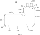
- the battery cell 100 further includes a fifth side surface 105, a sixth side surface 106 and a seventh side surface 107.
- the first side surface 101, the second side surface 102, the third side surface 103, the fourth side surface 104, the fifth side surface 105, the sixth side surface 106 and the seventh side surface 107 are sequentially disposed adjacent to each other and are connected to define an L shape, wherein the sixth side surface 106 is a concave arc-shaped surface as the inner side corner of the L-shaped battery cell.
- the second side surface 102 and the third side surface 103, the fourth side surface 104 and the fifth side surface 105, the fifth side surface 105 and the sixth side surface 106, the sixth side surface 106 and the seventh side surface 107, and the seventh side surface 107 and the first side surface 101 are respectively connected by one connection region (not shown).
- the adhesive film 60 may also be disposed on the abovementioned connection regions to bond the first electrode plate 10, the separator 30 and the second electrode plate 50.
- each of the edge of the first electrode plate 10 and the edge of the second electrode plate 50 may include a chamfered angle, a rounded angle or a combination of the two.
- the battery cell 100 further includes a first surface 100A and a second surface 100B which are perpendicular to the first direction and are disposed opposite to each other.
- the adhesive film 60 may also extend from the first connection region 101a, the second connection region 103a or/and other connection regions to the first surface 100A or/and the second surface 100B, which is beneficial to further improve the bonding stability of the adhesive film 60, thereby improving the safety of the battery cell.
- the adhesive film 60 extends from the first connection region 101a, the second connection region 103a or other connection regions to the first surface 100A or the second surface 100B with a width less than or equal to 2mm.
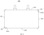
- the design solution of the battery cell in the present application is not limited to the L-shaped battery cell, and may also be the battery cells of other shapes, such as a rectangular battery cell (as shown in FIG. 8 ) and a polygonal battery cell.
- the abovementioned battery cell 100 is applied to an electrochemical device (not shown in the figure), and the electrochemical device may be, but not limited to, a battery.
- the adhesive film is disposed at the joint between two adjacent side surfaces of the battery cell to bond the first electrode plate, the separator and the second electrode plate, which can effectively reduce the impact of the battery cell on the encapsulation film encapsulating the battery cell, thereby reducing the risk of a damage to the encapsulation film.
- the structural stability of the battery cell can also be improved and the separator is prevented from turning over during subsequent use, thereby reducing the risk of short circuit of the battery cell, and further improving the safety of the battery cell.
Landscapes
- Chemical & Material Sciences (AREA)
- Chemical Kinetics & Catalysis (AREA)
- Electrochemistry (AREA)
- General Chemical & Material Sciences (AREA)
- Engineering & Computer Science (AREA)
- Manufacturing & Machinery (AREA)
- Materials Engineering (AREA)
- Secondary Cells (AREA)
- Connection Of Batteries Or Terminals (AREA)
- Sealing Battery Cases Or Jackets (AREA)
- Battery Mounting, Suspending (AREA)
Abstract
Description
- The present application relates to the field of batteries, and in particular, to a battery cell and an electrochemical device applying the battery cell.
- Batteries have been widely used in various electronic products due to the advantages such as high energy density, high working voltage, long cycle life, environmental protection and safety. Therefore, the requirements for safety of the batteries are increasingly high. The joint between two adjacent edges in a battery cell is relatively sharp, and is prone to damage an encapsulation film (aluminum-plastic film) encapsulating the battery cell when subjected to an external force, which further leads to corrosion of the battery and affects the safety of the battery.
- In view of the above situation, it is necessary to provide a battery cell favorable to improve the safety.
- In addition, it is further necessary to provide an electrochemical device applying the above battery cell.
- The battery cell according to the present application includes a first electrode plate, an separator and a second electrode plate which are stacked in sequence along a first direction, the battery cell further includes a first side surface and a second side surface which are disposed along the first direction and are adjacent to each other, the first side surface and the second side surface are connected by a first connection region, the battery cell further includes an adhesive film, and the adhesive film is disposed in the first connection region, and is used for bonding the first electrode plate, the separator and the second electrode plate.
- As a solution of the present application, the adhesive film is an adhesive layer or adhesive tape.
- As a solution of the present application, each of the first electrode plate and the second electrode plate includes a first edge corresponding to the first side surface, a second edge corresponding to the second side surface, and a first connection position corresponding to the first connection region, wherein each first connection position includes a chamfered angle or a rounded angle, so that the first connection region correspondingly forms a chamfered angle region or a rounded angle region, and the adhesive film is disposed in the chamfered angle region or the rounded angle region to bond the first electrode plate, the separator and the second electrode plate.
- As a solution of the present application, each first connection position includes a chamfered angle and a first rounded angle connected to the chamfered angle, one end of the chamfered angle deviated from the first rounded angle is connected to the first edge, and one end of the first rounded angle deviated from the chamfered angle is connected to the second edge.
- As a solution of the present application, the first connection position further includes a second rounded angle, and the second rounded angle is connected to the first edge and one end of the chamfered angle deviated from the first rounded angle.
- As a solution of the present application, a size of the first rounded angle is the same as or different from a size of the second rounded angle.
- As a solution of the present application, the battery cell further includes a third side surface and a fourth side surface which are disposed along the first direction and are adjacent to each other, the third side surface and the fourth side surface are connected by a second connection region, each of the first electrode plate and the second electrode plate includes a third edge corresponding to the third side surface, a fourth edge corresponding to the fourth side surface, and a second connection position corresponding to the second connection region, wherein each second connection position includes a chamfered angle or a rounded angle, and the adhesive film is also disposed in a chamfered angle region or a rounded angle region formed in the second connection region corresponding to the second connection position to bond the first electrode plate, the separator and the second electrode plate.
- As a solution of the present application, along a second direction perpendicular to a tangential direction of the first connection region, a thickness of a thickest part of the adhesive film is 20 microns to 100 microns.
- As a solution of the present application, the adhesive film further extends from the first connection region to the first side surface or the second side surface, and the adhesive film extends from the first connection region to the first side surface or the second side surface with a width less than or equal to 5 mm.
- As a solution of the present application, the battery cell further includes a first surface and a second surface which are perpendicular to the first direction and opposite to each other, the adhesive film also extends from the first connection region to the first surface or the second surface, and the adhesive film extends from the first connection region to the first surface or the second surface with a width less than or equal to 2 mm.
- As a solution of the present application, the adhesive film has viscosity at a temperature from normal temperature to 75°C.
- The electrochemical device according to the present application includes a housing and the battery cell as mentioned above, the battery cell being disposed in the housing.
- According to the battery cell and the electrochemical device applying the battery cell of the present application, the adhesive film is disposed at the joint between two adjacent side surfaces of the battery cell to bond the first electrode plate, the separator and the second electrode plate, which can effectively reduce the impact of the battery cell on the encapsulation film encapsulating the battery cell, and further reduce the risk of a damage to the encapsulation film. At the same time, the structural stability of the battery cell can also be improved and the separator is prevented from turning over during subsequent use, thereby reducing the risk of short circuit of the battery cell, and further improving the safety of the battery cell.
-
-
FIG. 1 is a schematic structural diagram of a battery cell according to an embodiment of the present application; -
FIG. 2 is a schematic structural diagram of a battery cell according to an embodiment of the present application; -
FIG. 3 is a partial schematic diagram of a battery cell according to an embodiment of the present application; -
FIG. 4 is a partially enlarged schematic diagram of a battery cell according to an embodiment of the present application; -
FIG. 5 is a partially enlarged schematic diagram of a battery cell according to an embodiment of the present application; -
FIG. 6 is a schematic structural diagram of a battery cell according to an embodiment of the present application; -
FIG. 7 is a schematic structural diagram of a battery cell according to an embodiment of the present application; and -
FIG. 8 is a schematic structural diagram of a battery cell according to an embodiment of the present application. - Illustration of reference signs of main
elements battery cell 100 first electrode plate 10 separator 30 second electrode plate 50 first side surface 101 second side surface 102 first connection region 100a adhesive film 60 first edge 11, 51 second edge 12, 52 first connection position 11a, 51a chamfered angle 111, 511 first rounded angle 113, 513 second rounded angle 115, 515 third side surface 103 fourth side surface 104 second connection region 103a third edge 13, 53 fourth edge 14, 54 second connection position 13a, 53a fifth side surface 105 sixth side surface 106 seventh side surface 107 first surface 100A second surface 100B - The following specific embodiments will further explain the present application in combination with the above accompanying drawings.
- The technical solutions in the embodiments of the present application will be clearly and completely described below in combination with the accompanying drawings in the embodiments of the present application. It is obvious that the described embodiments are only part but not all of the embodiments of the present application. All other embodiments obtained by those of ordinary skilled in the art without creative efforts based on the embodiments in the present application are within the protection scope of the present application.
- Unless otherwise defined, all technical and scientific terms used herein have the same meaning as generally understood by those skilled in the art to which the present application pertains. The terms used in the description of the present application herein are merely for the purpose of describing the particular embodiments, and are not intended to limit the present application.
- Some embodiments of the present application will be described in detail below in combination with the accompanying drawings. The embodiments described below and features in the embodiments may be combined with each other without conflict.
- Referring to
FIG. 1 to FIG. 3 , according to an embodiment of the present application, thebattery cell 100 includes afirst electrode plate 10, anseparator 30 and asecond electrode plate 50 which are sequentially stacked along a first direction. Thebattery cell 100 further includes afirst side surface 101 and asecond side surface 102 which are disposed along the first direction and are adjacent to each other, and thefirst side surface 101 and thesecond side surface 102 are connected by a first connection region 100a. Thebattery cell 100 further includes anadhesive film 60, and theadhesive film 60 is disposed in the first connection region 100a and is used for bonding thefirst electrode plate 10, theseparator 30 and thesecond electrode plate 50 which are stacked along the first direction, so that the impact of thebattery cell 100 on an encapsulation film encapsulating the battery cell in the case of an external force is reduced, the risk of a damage to the encapsulation film is reduced, meanwhile, structural stability of the battery cell can also be improved, and the separator is prevented from turning over during subsequent use, thereby reducing the risk of short circuit of the battery cell. In addition, when the encapsulation film encapsulates the battery cell, it is easy to form a redundant space corresponding to the connection region, and theadhesive film 60 disposed in the connection region can effectively utilize the redundant space to further improve the subsequent situation that an encapsulation structure of the battery cell is prone to collapse in the connection region, and at the same time, the risk that the infiltration of electrolyte is affected due to large-area gluing of the battery cell is also reduced. - The
adhesive film 60 may be an adhesive layer or an adhesive tape. The adhesive tape includes a base material layer, and an adhesive layer which is disposed on the base material layer, and may be, for example, but not limited to, a single-sided adhesive tape or green adhesive, etc. - Preferably, along a second direction perpendicular to a tangential direction of the
first connection region 101a, the thickness of a thickest part of theadhesive film 60 is 20 microns to 100 microns. - The
first electrode plate 10 includes afirst edge 11, asecond edge 12 and afirst connection position 11a, thefirst edge 11 and thesecond edge 12 are disposed adjacent to each other, and thefirst connection position 11a is connected to thefirst edge 11 and thesecond edge 12. - The
second electrode plate 50 includes afirst edge 51, asecond edge 52 and afirst connection position 51a, thefirst edge 51 and thesecond edge 52 are disposed adjacent to each other, and thefirst connection position 51a is connected to thefirst edge 51 and thesecond edge 52. - When the
first electrode plate 10, theseparator 30 and thesecond electrode plate 50 are stacked along the first direction, thefirst edges separator 30 sandwiched between thefirst edges first side surface 101 together, thesecond edges separator 30 sandwiched between thefirst edges second side surface 102 together, and thefirst connection positions separator 30 sandwiched between thefirst connection positions adhesive film 60 is used for bonding thefirst connection positions separator 30 sandwiched between thefirst connection positions - Each
first connection position first connection positions adhesive film 60 is disposed corresponding to the chamfered angles or rounded angles, which is beneficial to improve the energy density of the battery cell. In the present embodiment, thefirst connection positions - In some embodiments, please refer to
FIG. 4 , thefirst connection position 11a may include achamfered angle 111 and a firstrounded angle 113 connected to thechamfered angle 111, and thefirst connection position 51a may include achamfered angle 511 and a firstrounded angle 513 connected to thechamfered angle 511. The end of thechamfered angle 111 deviated from the firstrounded angle 113 is connected to thefirst edge 11, and the end of the firstrounded angle 113 deviated from thechamfered angle 111 is connected to thesecond edge 12; the end of thechamfered angle 511 deviated from the firstrounded angle 513 is connected to thefirst edge 51, and the end of the firstrounded angle 513 deviated from thechamfered angle 511 is connected to thesecond edge 52. - In some embodiments, please refer to
FIG. 5 , thefirst connection positions rounded angles rounded angle 115 is connected to the end of thechamfered angle 111 deviated from the firstrounded angle 113 and thefirst edge 11, and the secondrounded angle 515 is connected to the end of thechamfered angle 511 deviated from the firstrounded angle 513 and thefirst edge 51. - A size of the second
rounded angle 115 may be the same as or different from a size of the firstrounded angle 113, and a size of thesecond element 515 may be the same as or different from a size of the firstrounded angle 513. - In some embodiments, please refer to
FIG. 6 , theadhesive film 60 may also extend from the first connection region 100a to thefirst side surface 101 or/and thesecond side surface 102, which is beneficial to improve bonding stability of theadhesive film 60, thereby improving the safety of the battery cell. Preferably, theadhesive film 60 extends from the first connection region 100a to thefirst side surface 101 or thesecond side surface 102 with a width less than or equal to 5 mm. - Preferably, the
adhesive film 60 has viscosity at a temperature from normal temperature to 75°C. - The
battery cell 100 further includes athird side surface 103 and afourth side surface 104 which are disposed along the first direction and are adjacent to each other, and thethird side surface 103 and thefourth side surface 104 are connected by asecond connection region 103a. Theadhesive film 60 may also be disposed in thesecond connection region 103a to bond thefirst electrode plate 10, theseparator 30 and thesecond electrode plate 50 which are stacked along the first direction. Therefore, the impact of the battery cell on the encapsulation film encapsulating the battery cell is further reduced, the stability of the battery cell is improved, the risk of short circuit of the battery cell is reduced, and the safety of the battery cell is further improved. - The
first electrode plate 10 further includes athird edge 13, afourth edge 14 and asecond connection position 13a, thethird edge 13 and thefourth edge 14 are disposed adjacent to each other, and thesecond connection position 13a is connected to thethird edge 13 and thefourth edge 14. - The
second electrode plate 50 further includes athird edge 53, afourth edge 54 and asecond connection position 53a, thethird edge 53 and thefourth edge 54 are disposed adjacent to each other, and thesecond connection position 53a is connected to thethird edge 53 and thefourth edge 54. - When the
first electrode plate 10, theseparator 30 and thesecond electrode plate 50 are stacked along the first direction, thethird edges separator 30 sandwiched between thethird edges third side surface 103 together, thefourth edges separator 30 sandwiched between thefourth edges fourth side surface 104 together, and the second connection positions 13a and 53a and theseparator 30 sandwiched between the second connection positions 13a and 53a form thesecond connection region 103a together. Theadhesive film 60 disposed in thesecond connection region 103a is used for bonding the second connection positions 13a and 53a and theseparator 30 sandwiched between the second connection positions 13a and 53a. - Each
second connection position - In some embodiments, the second connection positions 13a and 53a may also include a combination of the chamfered angle and rounded angle like the
first connection position first connection positions - In some embodiments, the
adhesive film 60 may also extend from thesecond connection region 103a to thethird side surface 103 or/and thefourth side surface 104. Preferably, theadhesive film 60 extends from thesecond connection region 103a to thethird side surface 103 or thefourth side surface 104 with a width less than or equal to 5 mm. - The present application mainly takes an L-shaped battery cell as an example. As shown in
FIG. 2 , thebattery cell 100 further includes afifth side surface 105, asixth side surface 106 and aseventh side surface 107. Thefirst side surface 101, thesecond side surface 102, thethird side surface 103, thefourth side surface 104, thefifth side surface 105, thesixth side surface 106 and theseventh side surface 107 are sequentially disposed adjacent to each other and are connected to define an L shape, wherein thesixth side surface 106 is a concave arc-shaped surface as the inner side corner of the L-shaped battery cell. Thesecond side surface 102 and thethird side surface 103, thefourth side surface 104 and thefifth side surface 105, thefifth side surface 105 and thesixth side surface 106, thesixth side surface 106 and theseventh side surface 107, and theseventh side surface 107 and thefirst side surface 101 are respectively connected by one connection region (not shown). - The
adhesive film 60 may also be disposed on the abovementioned connection regions to bond thefirst electrode plate 10, theseparator 30 and thesecond electrode plate 50. - Preferably, by corresponding to each connection region, each of the edge of the
first electrode plate 10 and the edge of thesecond electrode plate 50 may include a chamfered angle, a rounded angle or a combination of the two. - The
battery cell 100 further includes afirst surface 100A and asecond surface 100B which are perpendicular to the first direction and are disposed opposite to each other. Please refer toFIG. 7 , theadhesive film 60 may also extend from thefirst connection region 101a, thesecond connection region 103a or/and other connection regions to thefirst surface 100A or/and thesecond surface 100B, which is beneficial to further improve the bonding stability of theadhesive film 60, thereby improving the safety of the battery cell. Preferably, theadhesive film 60 extends from thefirst connection region 101a, thesecond connection region 103a or other connection regions to thefirst surface 100A or thesecond surface 100B with a width less than or equal to 2mm. - Although the present application mainly takes the L-shaped battery cell as an example, the design solution of the battery cell in the present application is not limited to the L-shaped battery cell, and may also be the battery cells of other shapes, such as a rectangular battery cell (as shown in
FIG. 8 ) and a polygonal battery cell. - The
abovementioned battery cell 100 is applied to an electrochemical device (not shown in the figure), and the electrochemical device may be, but not limited to, a battery. - According to the battery cell and the electrochemical device applying the battery cell of the present application, the adhesive film is disposed at the joint between two adjacent side surfaces of the battery cell to bond the first electrode plate, the separator and the second electrode plate, which can effectively reduce the impact of the battery cell on the encapsulation film encapsulating the battery cell, thereby reducing the risk of a damage to the encapsulation film. At the same time, the structural stability of the battery cell can also be improved and the separator is prevented from turning over during subsequent use, thereby reducing the risk of short circuit of the battery cell, and further improving the safety of the battery cell.
- In addition, for those of ordinary skill in the art, various other corresponding alterations and transformations can be made according to technical concepts of the present application, and all these alterations and transformations should belong to the protection scope of the present application.
Claims (11)
- A battery cell, comprising a first electrode plate, an separator and a second electrode plate, wherein,the first electrode plate, the separator and the second electrode plate are stacked in sequence along a first direction;the battery cell further comprises a first side surface and a second side surface, wherein the first side surface and the second side surface are disposed along the first direction and are adjacent to each other, and the first side surface and the second side surface are connected by a first connection region, and characterized in that the battery cell further comprises an adhesive film, and the adhesive film is disposed in the first connection region, and is configured for bonding the first electrode plate, the separator and the second electrode plate.
- The battery cell according to claim 1, characterized in that each of the first electrode plate and the second electrode plate comprises a first edge corresponding to the first side surface, a second edge corresponding to the second side surface, and a first connection position corresponding to the first connection region, wherein each first connection position comprises a chamfered angle or a rounded angle, so that the first connection region correspondingly forms a chamfered angle region or a rounded angle region, and the adhesive film is disposed in the chamfered angle region or the rounded angle region to bond the first electrode plate, the separator and the second electrode plate.
- The battery cell according to claim 2, characterized in that each first connection position comprises a chamfered angle and a first rounded angle connected to the chamfered angle, one end of the chamfered angle deviated from the first rounded angle is connected to the first edge, and one end of the first rounded angle deviated from the chamfered angle is connected to the second edge.
- The battery cell according to claim 3, characterized in that the first connection position further comprises a second rounded angle, and the second rounded angle is connected to one end of the chamfered angle deviated from the first rounded angle and the first edge.
- The battery cell according to claim 4, characterized in that a size of the first rounded angle is the same as or different from a size of the second rounded angle.
- The battery cell according to claim 2, characterized in that, the battery cell further comprises a third side surface and a fourth side surface , the third side surface and the fourth side surface are disposed along the first direction and are adjacent to each other; wherein the third side surface and the fourth side surface are connected by a second connection region, each of the first electrode plate and the second electrode plate comprises a third edge corresponding to the third side surface, a fourth edge corresponding to the fourth side surface, and a second connection position corresponding to the second connection region, wherein each second connection position comprises a chamfered angle or a rounded angle, and the adhesive film is also disposed in a chamfered angle region or a rounded angle region formed in the second connection region corresponding to the second connection position to bond the first electrode plate, the separator and the second electrode plate.
- The battery cell according to any one of claims 1 to 6, characterized in that along a second direction perpendicular to a tangential direction of the first connection region, a thickness of a thickest part of the adhesive film is 20 microns to 100 microns.
- The battery cell according to any one of claims 1 to 6, characterized in that the adhesive film further extends from the first connection region to the first side surface or the second side surface, and the adhesive film extends from the first connection region to the first side surface or the second side surface with a width less than or equal to 5 mm.
- The battery cell according to any one of claims 1 to 6, characterized in that the battery cell further comprises a first surface and a second surface, the first surface and the second surface are perpendicular to the first direction and opposite to each other, the adhesive film also extends from the first connection region to the first surface or the second surface, and the adhesive film extends from the first connection region to the first surface or the second surface with a width less than or equal to 2 mm.
- The battery cell according to any one of claims 1 to 6, characterized in that the adhesive film has viscosity at a temperature from normal temperature to 75°C.
- An electrochemical device, comprising a housing, and characterized in that the electrochemical device further comprises the battery cell according to any one of claims 1 to 10, the battery cell being disposed in the housing.
Applications Claiming Priority (1)
| Application Number | Priority Date | Filing Date | Title |
|---|---|---|---|
| PCT/CN2020/082256 WO2021195909A1 (en) | 2020-03-31 | 2020-03-31 | Battery core and electrochemical device applying same |
Publications (2)
| Publication Number | Publication Date |
|---|---|
| EP4131541A1 true EP4131541A1 (en) | 2023-02-08 |
| EP4131541A4 EP4131541A4 (en) | 2023-07-26 |
Family
ID=77927354
Family Applications (1)
| Application Number | Title | Priority Date | Filing Date |
|---|---|---|---|
| EP20928678.0A Pending EP4131541A4 (en) | 2020-03-31 | 2020-03-31 | Battery core and electrochemical device applying same |
Country Status (6)
| Country | Link |
|---|---|
| US (1) | US12142732B2 (en) |
| EP (1) | EP4131541A4 (en) |
| JP (1) | JP7482248B2 (en) |
| KR (1) | KR102909564B1 (en) |
| CN (1) | CN114041224B (en) |
| WO (1) | WO2021195909A1 (en) |
Families Citing this family (4)
| Publication number | Priority date | Publication date | Assignee | Title |
|---|---|---|---|---|
| JP7482248B2 (en) | 2020-03-31 | 2024-05-13 | 寧徳新能源科技有限公司 | Battery cell and electrochemical device using the same |
| CN115552701B (en) * | 2021-12-02 | 2025-12-09 | 东莞新能源科技有限公司 | Batteries and Electronic Devices |
| KR102918051B1 (en) * | 2022-03-24 | 2026-01-27 | 삼성디스플레이 주식회사 | Display device |
| CN219626707U (en) * | 2022-10-31 | 2023-09-01 | 珠海冠宇电池股份有限公司 | Battery core |
Family Cites Families (28)
| Publication number | Priority date | Publication date | Assignee | Title |
|---|---|---|---|---|
| JP4720065B2 (en) * | 2001-09-04 | 2011-07-13 | 日本電気株式会社 | Film outer battery and battery pack |
| US7303594B2 (en) * | 2001-12-27 | 2007-12-04 | The Gillette Company | Battery electrode and method of making the same |
| US7001439B2 (en) * | 2003-04-02 | 2006-02-21 | The Gillette Company | Zinc/air cell assembly |
| US20040197645A1 (en) * | 2003-04-02 | 2004-10-07 | Keith Buckle | Zinc/air cell |
| CN2768215Y (en) * | 2005-01-14 | 2006-03-29 | 比亚迪股份有限公司 | A pole piece of a lithium ion battery and a lithium ion battery containing the pole piece |
| US7524577B2 (en) * | 2005-09-06 | 2009-04-28 | Oak Ridge Micro-Energy, Inc. | Long life thin film battery and method therefor |
| WO2009113470A1 (en) * | 2008-03-14 | 2009-09-17 | 日本電気株式会社 | Coating material and film-wrapped electric device |
| JP5527176B2 (en) | 2010-11-25 | 2014-06-18 | ソニー株式会社 | Non-aqueous electrolyte battery |
| CN201985201U (en) * | 2011-01-19 | 2011-09-21 | 哈尔滨光宇电源股份有限公司 | Lithium ion power battery pole piece with high safety |
| CN202395109U (en) * | 2011-12-19 | 2012-08-22 | 深圳市慧通天下科技股份有限公司 | Bottom-encapsulated lithium ion battery roll core |
| JP5742869B2 (en) * | 2013-04-16 | 2015-07-01 | 株式会社豊田自動織機 | Power storage device |
| US20150007864A1 (en) * | 2013-07-08 | 2015-01-08 | The Boeing Company | Adhesive Bonded Solar Cell Assembly |
| EP3069396A2 (en) * | 2013-11-13 | 2016-09-21 | R. R. Donnelley & Sons Company | Battery |
| KR20150072016A (en) | 2013-12-19 | 2015-06-29 | 주식회사 엘지화학 | Secondary battery and method of manufacturing the same |
| US20150188185A1 (en) * | 2013-12-31 | 2015-07-02 | Microsoft Corporation | Reinforcement of battery |
| KR102273786B1 (en) | 2014-08-13 | 2021-07-06 | 삼성에스디아이 주식회사 | Rechargeable battery |
| KR102288544B1 (en) | 2015-06-29 | 2021-08-11 | 삼성에스디아이 주식회사 | Secondary Battery And Fabricating Method Thereof |
| CN105355962B (en) * | 2015-11-25 | 2017-12-05 | 合肥国轩高科动力能源有限公司 | A kind of preparation method of wound laminated battery |
| KR101950464B1 (en) * | 2015-11-30 | 2019-02-20 | 주식회사 엘지화학 | Battery Cell of Irregular Structure with Improved Sealing Reliability of Cell Case |
| CN105514352B (en) * | 2015-12-14 | 2019-04-26 | 东莞新能源科技有限公司 | Electrode assembly and the lithium-ion electric core for using the electrode assembly |
| KR102278442B1 (en) | 2016-09-21 | 2021-07-16 | 삼성에스디아이 주식회사 | Rechargeable lithium battery |
| KR102503597B1 (en) * | 2017-11-16 | 2023-02-24 | 삼성에스디아이 주식회사 | Secondary battery |
| CN207602628U (en) * | 2017-11-29 | 2018-07-10 | 宁德新能源科技有限公司 | Electrode assembly and secondary cell |
| CN109860713B (en) | 2017-11-30 | 2022-03-29 | 宁德新能源科技有限公司 | Battery cell, electrochemical device and manufacturing method thereof |
| CN113131098B (en) | 2018-02-09 | 2024-05-14 | 宁德新能源科技有限公司 | Battery cell and battery |
| JP2020030899A (en) * | 2018-08-20 | 2020-02-27 | 積水化学工業株式会社 | Secondary battery |
| CN209544535U (en) * | 2019-05-07 | 2019-10-25 | 江西迪比科股份有限公司 | A kind of L-type stack type lithium ion battery |
| JP7482248B2 (en) | 2020-03-31 | 2024-05-13 | 寧徳新能源科技有限公司 | Battery cell and electrochemical device using the same |
-
2020
- 2020-03-31 JP JP2022557201A patent/JP7482248B2/en active Active
- 2020-03-31 CN CN202080035805.3A patent/CN114041224B/en active Active
- 2020-03-31 KR KR1020227035383A patent/KR102909564B1/en active Active
- 2020-03-31 EP EP20928678.0A patent/EP4131541A4/en active Pending
- 2020-03-31 WO PCT/CN2020/082256 patent/WO2021195909A1/en not_active Ceased
-
2022
- 2022-09-30 US US17/958,125 patent/US12142732B2/en active Active
Also Published As
| Publication number | Publication date |
|---|---|
| CN114041224A (en) | 2022-02-11 |
| EP4131541A4 (en) | 2023-07-26 |
| US12142732B2 (en) | 2024-11-12 |
| KR20220145911A (en) | 2022-10-31 |
| US20230043958A1 (en) | 2023-02-09 |
| KR102909564B1 (en) | 2026-01-08 |
| WO2021195909A1 (en) | 2021-10-07 |
| CN114041224B (en) | 2024-09-03 |
| JP7482248B2 (en) | 2024-05-13 |
| JP2023518550A (en) | 2023-05-02 |
Similar Documents
| Publication | Publication Date | Title |
|---|---|---|
| US12142732B2 (en) | Battery cell and electrochemical device including same | |
| US20230344019A1 (en) | Electrode assembly and electrochemical apparatus | |
| CN104919637B (en) | Electrode assembly with rounded corners | |
| CN211350702U (en) | Packaging structure of battery cell | |
| US20220102760A1 (en) | All-solid-state battery and method for manufacturing all-solid-state battery | |
| WO2022213379A1 (en) | Battery cell and electrical device | |
| CN113597702B (en) | Electrochemical device and electronic device | |
| US11075312B2 (en) | Solar cell module and method for manufacturing solar cell module | |
| US20230146401A1 (en) | Electrode plate, electrode assembly containing same, and battery | |
| US12322814B2 (en) | Packaging structure and battery core using the same | |
| CN113728495B (en) | Packaging structure of battery cell | |
| CN211088352U (en) | Package structure and battery cell using the package structure | |
| US10879016B2 (en) | Electrochemical device and method for manufacturing same | |
| US20180219194A1 (en) | Battery with front face and rear face contacts | |
| CN117637886A (en) | Photovoltaic modules | |
| CN212062471U (en) | Packaging structure and battery cell applying same | |
| JPH03108278A (en) | Thin type battery | |
| CN222088728U (en) | Cover plate patch, cover plate and battery cell | |
| CN218783073U (en) | A kind of battery and electronic equipment | |
| JP2001076691A (en) | Film-covered battery and method of manufacturing the same | |
| JPS61225770A (en) | flat battery | |
| KR20250000886U (en) | Battery cell structure | |
| JP2025066453A (en) | Laminate film, electrode laminate, and battery | |
| CN119815999A (en) | Back contact cell, photovoltaic module and manufacturing method thereof | |
| CN121039850A (en) | Secondary batteries and their manufacturing methods |
Legal Events
| Date | Code | Title | Description |
|---|---|---|---|
| STAA | Information on the status of an ep patent application or granted ep patent |
Free format text: STATUS: THE INTERNATIONAL PUBLICATION HAS BEEN MADE |
|
| PUAI | Public reference made under article 153(3) epc to a published international application that has entered the european phase |
Free format text: ORIGINAL CODE: 0009012 |
|
| STAA | Information on the status of an ep patent application or granted ep patent |
Free format text: STATUS: REQUEST FOR EXAMINATION WAS MADE |
|
| 17P | Request for examination filed |
Effective date: 20221028 |
|
| AK | Designated contracting states |
Kind code of ref document: A1 Designated state(s): AL AT BE BG CH CY CZ DE DK EE ES FI FR GB GR HR HU IE IS IT LI LT LU LV MC MK MT NL NO PL PT RO RS SE SI SK SM TR |
|
| DAV | Request for validation of the european patent (deleted) | ||
| DAX | Request for extension of the european patent (deleted) | ||
| A4 | Supplementary search report drawn up and despatched |
Effective date: 20230628 |
|
| RIC1 | Information provided on ipc code assigned before grant |
Ipc: H01M 50/20 20210101ALI20230622BHEP Ipc: H01M 50/14 20210101ALI20230622BHEP Ipc: H01M 50/102 20210101ALI20230622BHEP Ipc: H01M 10/0585 20100101ALI20230622BHEP Ipc: H01M 10/04 20060101ALI20230622BHEP Ipc: H01M 10/0525 20100101AFI20230622BHEP |