EP4131528A1 - Battery - Google Patents
Battery Download PDFInfo
- Publication number
- EP4131528A1 EP4131528A1 EP20929099.8A EP20929099A EP4131528A1 EP 4131528 A1 EP4131528 A1 EP 4131528A1 EP 20929099 A EP20929099 A EP 20929099A EP 4131528 A1 EP4131528 A1 EP 4131528A1
- Authority
- EP
- European Patent Office
- Prior art keywords
- insulation layer
- adhesion
- battery
- electrode assembly
- adhesion portion
- Prior art date
- Legal status (The legal status is an assumption and is not a legal conclusion. Google has not performed a legal analysis and makes no representation as to the accuracy of the status listed.)
- Pending
Links
Images


Classifications
-
- H—ELECTRICITY
- H01—ELECTRIC ELEMENTS
- H01M—PROCESSES OR MEANS, e.g. BATTERIES, FOR THE DIRECT CONVERSION OF CHEMICAL ENERGY INTO ELECTRICAL ENERGY
- H01M50/00—Constructional details or processes of manufacture of the non-active parts of electrochemical cells other than fuel cells, e.g. hybrid cells
- H01M50/10—Primary casings; Jackets or wrappings
- H01M50/14—Primary casings; Jackets or wrappings for protecting against damage caused by external factors
-
- H—ELECTRICITY
- H01—ELECTRIC ELEMENTS
- H01M—PROCESSES OR MEANS, e.g. BATTERIES, FOR THE DIRECT CONVERSION OF CHEMICAL ENERGY INTO ELECTRICAL ENERGY
- H01M10/00—Secondary cells; Manufacture thereof
- H01M10/04—Construction or manufacture in general
- H01M10/0431—Cells with wound or folded electrodes
-
- H—ELECTRICITY
- H01—ELECTRIC ELEMENTS
- H01M—PROCESSES OR MEANS, e.g. BATTERIES, FOR THE DIRECT CONVERSION OF CHEMICAL ENERGY INTO ELECTRICAL ENERGY
- H01M10/00—Secondary cells; Manufacture thereof
- H01M10/04—Construction or manufacture in general
- H01M10/0436—Small-sized flat cells or batteries for portable equipment
-
- H—ELECTRICITY
- H01—ELECTRIC ELEMENTS
- H01M—PROCESSES OR MEANS, e.g. BATTERIES, FOR THE DIRECT CONVERSION OF CHEMICAL ENERGY INTO ELECTRICAL ENERGY
- H01M10/00—Secondary cells; Manufacture thereof
- H01M10/05—Accumulators with non-aqueous electrolyte
- H01M10/052—Li-accumulators
- H01M10/0525—Rocking-chair batteries, i.e. batteries with lithium insertion or intercalation in both electrodes; Lithium-ion batteries
-
- H—ELECTRICITY
- H01—ELECTRIC ELEMENTS
- H01M—PROCESSES OR MEANS, e.g. BATTERIES, FOR THE DIRECT CONVERSION OF CHEMICAL ENERGY INTO ELECTRICAL ENERGY
- H01M10/00—Secondary cells; Manufacture thereof
- H01M10/05—Accumulators with non-aqueous electrolyte
- H01M10/058—Construction or manufacture
- H01M10/0587—Construction or manufacture of accumulators having only wound construction elements, i.e. wound positive electrodes, wound negative electrodes and wound separators
-
- H—ELECTRICITY
- H01—ELECTRIC ELEMENTS
- H01M—PROCESSES OR MEANS, e.g. BATTERIES, FOR THE DIRECT CONVERSION OF CHEMICAL ENERGY INTO ELECTRICAL ENERGY
- H01M50/00—Constructional details or processes of manufacture of the non-active parts of electrochemical cells other than fuel cells, e.g. hybrid cells
- H01M50/10—Primary casings; Jackets or wrappings
- H01M50/116—Primary casings; Jackets or wrappings characterised by the material
- H01M50/124—Primary casings; Jackets or wrappings characterised by the material having a layered structure
- H01M50/126—Primary casings; Jackets or wrappings characterised by the material having a layered structure comprising three or more layers
-
- H—ELECTRICITY
- H01—ELECTRIC ELEMENTS
- H01M—PROCESSES OR MEANS, e.g. BATTERIES, FOR THE DIRECT CONVERSION OF CHEMICAL ENERGY INTO ELECTRICAL ENERGY
- H01M50/00—Constructional details or processes of manufacture of the non-active parts of electrochemical cells other than fuel cells, e.g. hybrid cells
- H01M50/10—Primary casings; Jackets or wrappings
- H01M50/131—Primary casings; Jackets or wrappings characterised by physical properties, e.g. gas permeability, size or heat resistance
- H01M50/133—Thickness
-
- H—ELECTRICITY
- H01—ELECTRIC ELEMENTS
- H01M—PROCESSES OR MEANS, e.g. BATTERIES, FOR THE DIRECT CONVERSION OF CHEMICAL ENERGY INTO ELECTRICAL ENERGY
- H01M2220/00—Batteries for particular applications
- H01M2220/30—Batteries in portable systems, e.g. mobile phone, laptop
-
- Y—GENERAL TAGGING OF NEW TECHNOLOGICAL DEVELOPMENTS; GENERAL TAGGING OF CROSS-SECTIONAL TECHNOLOGIES SPANNING OVER SEVERAL SECTIONS OF THE IPC; TECHNICAL SUBJECTS COVERED BY FORMER USPC CROSS-REFERENCE ART COLLECTIONS [XRACs] AND DIGESTS
- Y02—TECHNOLOGIES OR APPLICATIONS FOR MITIGATION OR ADAPTATION AGAINST CLIMATE CHANGE
- Y02E—REDUCTION OF GREENHOUSE GAS [GHG] EMISSIONS, RELATED TO ENERGY GENERATION, TRANSMISSION OR DISTRIBUTION
- Y02E60/00—Enabling technologies; Technologies with a potential or indirect contribution to GHG emissions mitigation
- Y02E60/10—Energy storage using batteries
-
- Y—GENERAL TAGGING OF NEW TECHNOLOGICAL DEVELOPMENTS; GENERAL TAGGING OF CROSS-SECTIONAL TECHNOLOGIES SPANNING OVER SEVERAL SECTIONS OF THE IPC; TECHNICAL SUBJECTS COVERED BY FORMER USPC CROSS-REFERENCE ART COLLECTIONS [XRACs] AND DIGESTS
- Y02—TECHNOLOGIES OR APPLICATIONS FOR MITIGATION OR ADAPTATION AGAINST CLIMATE CHANGE
- Y02P—CLIMATE CHANGE MITIGATION TECHNOLOGIES IN THE PRODUCTION OR PROCESSING OF GOODS
- Y02P70/00—Climate change mitigation technologies in the production process for final industrial or consumer products
- Y02P70/50—Manufacturing or production processes characterised by the final manufactured product
Definitions
- This application relates to a battery.
- This application provides a battery, including an electrode assembly, a first insulation layer, a second insulation layer, and at least one first adhesion portion.
- the electrode assembly includes a first surface and a second surface provided back away from the first surface.
- the first insulation layer is provided on the first surface.
- the second insulation layer is provided on the first surface and spaced apart from the first insulation layer.
- the first adhesion portion is provided on the first surface and located in a zone between the first insulation layer and the second insulation layer.
- the battery includes two or more first adhesion portions, and the two or more first adhesion portions are arranged into a dot array.
- the battery further includes a second adhesion portion provided on a side of the first insulation layer facing away from the first surface.
- an area of an orthographic projection of the second adhesion portion onto the first surface is smaller than an area of an orthographic projection of the first insulation layer onto the first surface.
- the battery includes at least two second adhesion portions, and the at least two second adhesion portions are arranged into a dot array.
- the first insulation layer extends from the first surface to the second surface
- the second insulation layer extends from the first surface to the second surface
- a metal portion is further provided at an end of the electrode assembly, and the first insulation layer and the second insulation layer are located at an end of the electrode assembly away from the metal portion.
- an area of an orthographic projection of the at least one first adhesion portion onto the first surface is smaller than a total area of an orthographic projection of the first insulation layer and the second insulation layer onto the first surface.
- the area of the an orthographic projection of the at least one first adhesion portion onto the first surface is smaller than an area of an orthographic projection of the first insulation layer onto the first surface, and is smaller than an area of an orthographic projection of the second insulation layer onto the first surface.
- a distance from a part of a zone of the first surface in which the first surface is in contact with the first insulation layer to the second surface is a first distance
- a distance from the first adhesion portion to the second surface is a second distance
- the first distance is less than the second distance
- a distance from a part of a zone of the first surface in which the first surface is in contact with the second insulation layer to the second surface is a third distance, and the third distance is less than the second distance.
- the first distance and the third distance are unequal.
- a length of the first adhesion portion in a first direction is less than a half of a length of the first surface in the first direction.
- the first surface is provided with a first groove corresponding to the first adhesion portion, and the first adhesion portion is located in the first groove.
- a surface of the first insulation layer corresponding to the second adhesion portion is provided with a second groove, and the second adhesion portion is located in the second groove.
- the battery further includes a third adhesion portion provided on a surface of the first insulation layer facing away from the second surface, and the third adhesion portion extends to a zone of the first surface that is not provided with the first insulation layer.
- the battery further includes a fourth adhesion portion, the fourth adhesion portion is provided on the first surface, a zone of the first surface that is provided with the fourth adhesion portion is spaced apart from a zone of the first surface that is provided with the first insulation layer and the second insulation layer and a zone of the first surface that is located between the first insulation layer and the second insulation layer, and the fourth adhesion portion is in contact with neither the first insulation layer nor the second insulation layer.
- the electrode assembly includes at least two fourth adhesion portions with different orthographic projection shapes, and the fourth adhesion portions are arranged into a dot array.
- the electrode assembly further includes a third insulation layer, the electrode assembly is of a winding structure, and the third insulation layer is provided on the second surface and fastened to an end of an outermost electrode plate of the electrode assembly.
- the battery further includes a housing, and the housing encloses the electrode assembly, the first insulation layer, and the second insulation layer, and adheres to the electrode assembly through the first adhesion portion.
- an average area of an an orthographic projection of the fourth adhesion portions onto the first surface is greater than an average area of an orthographic projection of the first adhesion portions onto the first surface.
- an average area of an orthographic projection of the third adhesion portions onto the first surface is greater than an average area of an orthographic projection of the first adhesion portions onto the first surface and greater than an average area of an orthographic projection of the second adhesion portions onto the first surface.
- the first insulation layer and the second insulation layer are provided on the surface of the electrode assembly, and the first adhesion portion is provided between the first insulation layer and the second insulation layer.
- the first adhesion portion adheres to the electrode assembly and the housing, thereby improving safety of the battery and prolonging service life of the battery when the battery is subject to an external force.
- Electrode assembly 10 10' First insulation layer 20 Second insulation layer 30 First adhesion portion 40 First surface 101, 101' Second surface 103, 103' Connection zone 105, 105' Electrode plate 11 First end 101A Second end 101B First conductive layer 10A First isolation layer 10B Second conductive layer 10C Second isolation layer 10D Surface 10a, 10b, 10c, 21, 31 Stacked body 10E, 10Ea Current collector 10AA, 10CA Active substance layer 10AB, 10CB First portion 106, 106' First section 101b1, 101b1' Second portion 107, 107' Second section 101b2, 101b2' Third portion 108 Fourth portion 109 Metal portion 15, 15' First metal portion 151 Second metal portion 153 Third edge 19A Fourth edge 19B First direction X First edge 16, 16', 16A Second direction Y Gap zone 101a, 101a' First recess 120 Second recess 130 First groove 140 Third direction Z Housing 80 Second adhesion portion 50 Second groove 150 Third adhesion portion 60 Fourth adhesion portion 70 Zone 101b, 101
- a space-related term such as "on” may be used herein for ease of description of a relationship between an element or feature and another element (a plurality of elements) or feature (a plurality of features) as illustrated in the figure. It should be understood that, in addition to the direction illustrated in the figure, the space-related term is intended to include different directions during use or operation of a device or an apparatus. For example, if the device in the figure is turned over, an element described to be “over” or “on” another element or feature is to be at an direction “under” or "beneath” said another element or feature. Therefore, the example term “on” may include directions of "over” and "beneath”.
- first, second, third, and the like may be used herein to describe various elements, components, zones, layers, and/or portions, these elements, components, zones, layers and/or portions, which are not subject to a limitation by the terms. These terms are used to distinguish an element, component, zone, layer or portion from another element, component, zone, layer, or portion. Therefore, the first element, component, zone, layer, or portion described below may be referred to as the second element, component, zone, layer, or portion without departing from teachings of the exemplary embodiments.
- the first direction may be any direction in a plane in which the first surface is located.
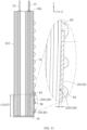
- a battery 100 includes an electrode assembly 10, a first insulation layer 20, a second insulation layer 30, and a first adhesion portion 40.
- the electrode assembly 10 includes a first surface 101, a second surface 103 provided back away from the first surface 101, and a connection zone 105 connecting the first surface 101 and the second surface 103.
- the electrode assembly 10 includes an electrode plate 11 and a separator (not shown), and the electrode plate 11 and the separator are wound to form a winding structure.
- the first surface 101, the second surface 103, and the connection zone 105 serve as a portion of an outer surface of the electrode assembly 10.
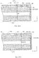
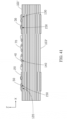
- FIG. 1 shows a structure formed by winding the electrode assembly 10 a plurality of times.
- the electrode assembly 10 has a plurality of bent portions in a direction, that is, a direction X in the figure, and the plurality of bent portions are respectively distributed on opposite sides of a center of the battery 100 in the direction X, that is, left and right sides in FIG. 1 .
- a connection zone between an outer plane of the electrode assembly 10 and an end of a bent portion on an outermost side of a left side of a center of the battery 100 that is closest to the center of the battery 100 is a first end 101A; and a connection zone between the outer plane of the electrode assembly 10 and an end of a bent portion on an outermost side of a right side of the center of the battery 100 that is closest to the center of the battery 100 is a second end 101B.
- the first surface 101 is, for example, a zone enclosed by the first end 101A, the second end 101B, and two ends of the electrode assembly 10 in a direction Y, that is, a first edge 16 and a second edge 18 when viewed in a direction Z shown in FIG. 1 .
- the electrode assembly 10 includes four edges perpendicular to the direction Z, and a zone enclosed by the four edges is the second surface 103.
- the electrode assembly 10 is further described by using an example below.
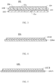
- the battery assembly 10 may include: a first conductive layer 10A, a first isolation layer 10B, a second conductive layer 10C, and a second isolation layer 10D.
- the first isolation layer 10B is formed on a surface 10a of the first conductive layer 10A.
- the second conductive layer 10C is formed on a surface 10b of the first isolation layer 10B away from the first conductive layer 10A.
- the second isolation layer 10D is formed on a surface 10c of the second conductive layer 10C facing away from the first isolation layer 10B.
- a stacked body 10E may be formed, and the electrode assembly 10 may be formed on the basis of the stacked body 10E.
- the first conductive layer 10A when viewed in a direction perpendicular to the surface 10a, the first conductive layer 10A may be, for example, rectangular.
- the first conductive layer 10A may be, for example, formed by stacking a current collector 10AA and an active substance layer 10AB.
- the current collector 10AA may, for example, at least include but is not limited to one or more of conductive metal thin plates such as an aluminum mesh and aluminum foil.
- the active substance layer 10AB may, for example, at least include but is not limited to one or more of lithium cobalt oxide, lithium nickel cobalt manganate, lithium nickel cobalt aluminate, lithium manganate oxide, lithium nickel oxide, lithium manganese iron phosphate, lithium vanadium phosphate, lithium vanadyl phosphate, lithium iron phosphate, lithium titanate, and a lithium-rich manganese-based material.
- the first conductive layer 10A may, for example, serve as a positive electrode plate to form the electrode assembly 10 of the battery 100.
- the first isolation layer 10B when viewed in a direction perpendicular to the surface 10b, the first isolation layer 10B may be, for example, rectangular.
- the first isolation layer 10B may, for example, at least include but is not limited to at least one or more of polyethylene, polypropylene, polyethylene terephthalate, polyimide, and aramid.
- the first isolation layer 10B may, for example, serve as a separator to form the electrode assembly 10 of the battery 100.
- the second conductive layer 10C when viewed in a direction perpendicular to the surface 10c, the second conductive layer 10C may be, for example, rectangular.
- the second conductive layer 10C may be, for example, formed by stacking a current collector 10CA and an active substance layer 10CB.
- the current collector 10CA may, for example, at least include but is not limited to one or two of conductive metal thin plates such as nickel foil and copper foil.
- the active substance layer 10CB may, for example, at least include but is not limited to one or more of graphite, soft carbon, hard carbon, graphene, a meso-carbon microbead, a silicon-based material, a tin-based material, lithium titanate, or another metal that may form an alloy with lithium.
- the second conductive layer 10C may, for example, serve as a negative electrode plate to form the electrode assembly 10 of the battery 100.
- the second isolation layer 10D When viewed in a direction perpendicular to the surface 10b, the second isolation layer 10D may be, for example, rectangular.
- the second isolation layer 10D may, for example, at least include but is not limited to at least one or more of polyethylene, polypropylene, polyethylene terephthalate, polyimide, and aramid.
- the second isolation layer 10D may, for example, serve as a separator to form the electrode assembly 10 of the battery 100.
- the electrode assembly 10 may be, for example, formed by winding a stacked body 10Ea formed by stacking a plurality of stacked bodies 10E.
- the electrode assembly 10 may be formed by directly stacking a plurality of stacked bodies 10E along the direction Z.
- the outer surface of the electrode assembly 10 includes the first surface 101 and the second surface 103 facing away from the first surface 101.
- the outer surface of the electrode assembly 10 further includes the connection zone 105 perpendicular to the first surface 101 in the third direction Z.
- the second surface 103 is, for example, a zone corresponding to a plane of the electrode assembly 10 back away from the first surface 101 and a zone enclosed by the first end 101A, the second end 101B, and the two ends of the electrode assembly 10 in the direction Y, that is, the first edge 16 and the second edge 18, when viewed in the direction Z shown in FIG. 1 .
- connection zone 105 includes a first portion 106 and a second portion 107 back away from the first portion 106.
- the electrode assembly 10 may further include a metal portion 15, and the metal portion 15 is provided on the first portion 106.
- An end of the metal portion 15 is connected to the electrode plate 11, and the other end may be connected to another electronic component, to implement feasible electrical connectivity between the electrode assembly 10 and said electronic component.
- the first insulation layer 20 and the second insulation layer 30 are both provided on the first surface 101, and the first insulation layer 20 and the second insulation layer 30 are spaced apart along the first direction X.
- the first insulation layer 20 when viewed in the third direction Z, may be, for example, rectangular.
- the first insulation layer 20 may, for example, at least include but is not limited to one or more of polyimide, polyvinyl chloride, polyethylene, and polypropylene.
- the second insulation layer 30 when viewed in the third direction Z, may be, for example, rectangular.
- the second insulation layer 30 may, for example, at least include but is not limited to one or more of polyimide, polyvinyl chloride, polyethylene, and polypropylene.
- the first surface 101 and the second portion 107 intersect at the first edge 16.
- the first direction X is a direction in which the first edge 16 is located.
- the first insulation layer 20 and the second insulation layer 30 each extend from the first edge 16 along the first surface 101 toward the first portion 106 but do not reach the first portion 106.
- a length L1 of the first insulation layer 20 extending from the first edge 16 toward the first portion 106 and a length L2 of the second insulation layer 30 extending from the first edge 16 toward the first portion 106 are not particularly limited in a case that the first insulation layer 20 apart from the first portion 106 and the second insulation layer 30 apart from the first portion 106.
- the length L1 of the first insulation layer 20 extending from the first edge 16 toward the first portion 106 is equal to the length L2 of the second insulation layer 30 extending from the first edge 16 toward the first portion 106.
- the foregoing length direction is defined as the second direction Y
- the first insulation layer 20 and the second insulation layer 30 may each include an adhesive layer and a substrate that are laminated.
- the adhesive layer adheres to the substrate and the electrode assembly 10.
- the adhesive layer may, for example, at least include but is not limited to at least one or more of natural rubber, synthetic rubber, acrylate, silica gel, and ethylene-vinyl acetate.
- the substrate may, for example, at least include but is not limited to at least one or more of polyethylene, polypropylene, Teflon, polyvinyl chloride, polyimide, and non-woven fabric.
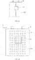
- the first adhesion portion 40 when viewed in the third direction Z perpendicular to the first surface 101, the first adhesion portion 40 is provided on the first surface 101 and located in a zone 101a between the first insulation layer 20 and the second insulation layer 30. In the second direction Y, the first adhesion portion 40 extends beyond neither the first insulation layer 20 nor the second insulation layer 30. In some embodiments, a length of the zone 101a in the first direction X may be less than a half of a length of the first surface 101 in the first direction X.
- an area of an orthographic projection of the first adhesion portion 40 onto the first surface 101 may be less than a total area of an orthographic projection of the first insulation layer 20 and the second insulation layer 30 onto the first surface 101. Further, in some embodiments, the area of the orthographic projection of the first adhesion portion 40 onto the first surface 101 may be less than an area of an orthographic projection of the first insulation layer 20 onto the first surface 101, and may also be less than an area of an orthographic projection of the second insulation layer 30 onto the first surface 101.
- the first adhesion portion 40 may, for example, at least include but is not limited to one polymer or a mixture formed by a combination of any polymers in cellulose, poly(vinylidene fluoride-co-hexafluoropropylene), poly(vinylidene fluoride-co-trichloroethylene), polymethyl methacrylate, poly butyl acrylate, polyacrylonitrile, polyvinylpyrrolidone, polyvinyl acetate, polyethylene-co-vinyl acetate, polyethylene oxide, polyarylate, cellulose acetate, cellulose acetate butyrate, cellulose acetate propionate, cyanoethyl pullulan, cyanoethyl polyvinyl alcohol, cyanoethyl cellulose, cyanoethyl sucrose, pullulan, carboxymethyl cellulose, and polypropylene-maleic anhydride.
- a first distance H1 from at least a part of an overlapped zone of the first surface 101 and the first insulation layer 20 to the second surface 103 is less than a second distance H2 from the first adhesion portion 40 to the second surface 103.
- distances from different locations in the at least a part of an overlapped zone of the first surface 101 and the first insulation layer 20 to the second surface 103 may be different. Further, referring to FIG. 1 , FIG. 9A , and FIG.
- the first distance H1 from a corresponding bottom portion of the first insulation layer 20 on the first surface 101 to the second surface 103 is less than the second distance H2 from the first adhesion portion 40 to the second surface 103.
- a first recess 120 is provided on the first surface 101, and the first recess 120 is such provided that it extends from the first edge 16 toward the first portion 106. At least a portion of the first insulation layer 20 further away from the first portion 106 is provided in the first recess 120.
- the first recess 120 may be an inclined groove whose depth gradually decreases from the first edge 16 toward the first portion 106 along the second direction Y A portion of the first insulation layer 20 close to the first portion 106 may be located outside the first recess 120.
- a third distance H3 from at least a part of an overlapped zone of the first surface 101 and the second insulation layer 30 to the second surface 103 is less than the second distance H2.
- the third distance H3 is less than the second distance H2
- distances from different locations in the at least a part of an overlapped zone of the first surface 101 and the second insulation layer 30 to the second surface 103 may be different.
- the third distance H3 from a corresponding bottom portion of the second insulation layer 30 on the first surface 101 to the second surface 103 is less than the second distance H2.
- a second recess 130 is provided on the first surface 101, and the second recess 130 is such provided that it extends from the first edge 16 toward the first portion 106. At least a portion of the second insulation layer 30 further away from the first portion 106 is provided in the second recess 130.
- the second recess 130 may be an inclined groove whose depth gradually decreases from the first edge 16 toward the first portion 106 along the second direction Y A portion of the second insulation layer 30 close to the first portion 106 may be located outside the second recess 130.
- the first distance H1 may not be equal to the third distance H3.
- the first surface 101 may be provided with a first groove 140, and the first adhesion portion 40 is located in the first groove 140.
- first adhesion portions 40 there are a plurality of first grooves 140, and each first adhesion portion 40 is located in one first groove 140.
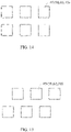
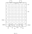
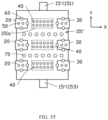
- the shape When viewed in the third direction Z, neither a shape nor a size of the first adhesion portion 40 is limited, and the shape may be a round shape (refer to FIG. 9A ), a rectangular shape (refer to FIG. 14 and FIG. 15 ), a strip shape (refer to FIG. 16 ), another regular or irregular shape, or a combination of these graphics.
- the number of the first adhesion portions 40 may also be set as actually needed, and may be one or more. When there are a plurality of first adhesion portions 40, the plurality of first adhesion portions 40 are spaced apart (for example, arranged into a dot array).
- the battery 100 When viewed in the third direction Z, the battery 100 may include at least two first adhesion portions 40 (refer to FIG.
- first adhesion portions 40 may also be the same.
- the battery 100 may further include a housing 80.
- the housing 80 may be, for example, but is not limited to, one or more of an aluminum-plastic film, a heat shrinkable film, an aluminum housing, and a steel housing.
- the housing 80 encloses the electrode assembly 10, the first insulation layer 20, and the second insulation layer 30, and adheres to the electrode assembly 10 through the first adhesion portion 40 (refer to both FIG. 20A and FIG. 20B ).
- the housing 80 may be provided with a groove 140', and a portion of the first adhesion portion 40 is located in the groove 140'.
- the first adhesion portion 40 is provided in the zone 101a between the first insulation layer 20 and the second insulation layer 30, so that compression degrees of a zone in which each of the first insulation layer 20 and the second insulation layer 30 is provided in the battery 100 and a zone corresponding to the zone 101a in the battery during chemical conversion are more uniform in a horizontal direction, that is, along the first direction X and the second direction Y, thereby helping reduce a deformation degree of the battery 100 during use.
- Providing the first adhesion portion 40 between the first insulation layer 20 and the second insulation layer 30 may increase an adhesion force between the electrode assembly 10 and the housing 80, to suppress relative displacement between the electrode assembly 10 and the housing 80 when the battery 100 is subject to an external force, thereby further reducing a possibility of damage to the battery 100 due to the external force and prolonging service life of the battery 100.
- the first adhesion portion 40 adheres to the housing 80 and the electrode assembly 10, thereby further helping suppress deformation of the electrode assembly 10.
- a shape of the first adhesion portion 40 after adhesion to the housing 80 may change.
- the plurality of first adhesion portions 40 may be spaced apart, or adjacent first adhesion portions 40 are connected to each other (refer to FIG. 16 ).
- an arrangement of the first adhesion portion 40 is more flexible, a location for providing the first adhesion portion 40 may be more accurate, and thicknesses after adhesion of the first adhesion portions 40 to the housing 80 may be more consistent.
- the battery 100 may further include a second adhesion portion 50, and the second adhesion portion 50 is provided on a surface 21 of the first insulation layer 20 facing away from the second surface 103.
- An area of an orthographic projection of the second adhesion portion 50 onto the first surface 101 is less than an area of an orthographic projection of the first insulation layer 20 onto the first surface 101.
- a surface 31 of the second insulation layer 30 facing away from the second surface 103 may also be provided with the second adhesion portion 50.
- an area of an orthographic projection of the second adhesion portion 50 onto the first surface 101 is less than an area of an orthographic projection of the second insulation layer 30 onto the first surface 101.
- the second adhesion portion 50 may, for example, at least include but is not limited to one polymer or a mixture formed by a combination of any polymers in cellulose, poly(vinylidene fluoride-co-hexafluoropropylene), poly(vinylidene fluoride-co-trichloroethylene), polymethyl methacrylate, poly butyl acrylate, polyacrylonitrile, polyvinylpyrrolidone, polyvinyl acetate, polyethylene-co-vinyl acetate, polyethylene oxide, polyarylate, cellulose acetate, cellulose acetate butyrate, cellulose acetate propionate, cyanoethyl pullulan, cyanoethyl polyvinyl alcohol, cyanoethyl cellulose, cyanoethyl sucrose, pullulan, carboxymethyl cellulose, and polypropylene-maleic anhydride.
- a shape of the second adhesion portion 50 is not limited, and the shape may be a round shape, a rectangular shape, a strip shape, another regular or irregular shape, or a combination of these graphics.
- the number of the second adhesion portions 50 may also be set as actually needed, and may be one or more.
- the battery 100 may include at least two second adhesion portions 50 with different shapes. In some embodiments, when viewed in the third direction Z, shapes of all the second adhesion portions 50 may also be the same.
- a surface of the first insulation layer 20 facing away from the second surface 103 is provided with a second groove 150, and the second adhesion portion 50 is located in the second groove 150.
- the housing 80 adheres to the first insulation layer 20 through the second adhesion portion 50, which facilitates stability between the electrode assembly 10 and the housing 80.
- the housing 80 may alternatively adhere to the second insulation layer 30 through the second adhesion portion 50, which facilitates the stability between the electrode assembly 10 and the housing 80.
- the housing 80 may alternatively adhere to the first insulation layer 20 and the second insulation layer 30 through the second adhesion portion 50.
- the second adhesion portion 50 avoids direct adhesion to the electrode assembly 10.
- the second adhesion portion 50 adheres to the housing 80 and the first insulation layer 20, or adheres to the housing 80 and the second insulation layer 30 instead of the housing 80 and the electrode assembly 10, the area of the orthographic projection of the second adhesion portion 50 onto the first surface 101 is less than the area of the orthographic projection of the first insulation layer 20 or the second insulation layer 30 onto the first surface 101 that adheres to the second adhesion portion 50, that is, a contact area between the first insulation layer 20 or the second insulation layer 30 and the electrode assembly 10 is larger, and therefore, a pulling force of the housing 80 on the electrode assembly 10 through the second adhesion portion 50 is dispersed, thereby reducing a probability of damage caused by pulling the electrode assembly 10, and reducing a risk of a short circuit between the positive and negative electrodes caused thereby.
- the plurality of second adhesion portions 50 may be spaced apart, or adjacent second adhesion portions 50 are connected to each other.
- an arrangement of the second adhesion portion 50 is more flexible, a location for providing the second adhesion portion 50 may be more accurate, and thicknesses after adhesion of the second adhesion portions 50 to the housing 80 may be more consistent.
- the housing 80 may be further provided with a groove 150', and a portion of the second adhesion portion 50 is located in the groove 150'.
- the battery 100 may further include a third adhesion portion 60, and the third adhesion portion 60 is provided on a surface 21 of the first insulation layer 20 facing away from the second surface 103, and extends across an intersection zone of the first insulation layer 20 and the first surface 101 to the first surface 101.
- the third adhesion portion 60 may, for example, at least include but is not limited to one polymer or a mixture formed by a combination of any polymers in cellulose, poly(vinylidene fluoride-co-hexafluoropropylene), poly(vinylidene fluoride-co-trichloroethylene), polymethyl methacrylate, poly butyl acrylate, polyacrylonitrile, polyvinylpyrrolidone, polyvinyl acetate, polyethylene-co-vinyl acetate, polyethylene oxide, polyarylate, cellulose acetate, cellulose acetate butyrate, cellulose acetate propionate, cyanoethyl pullulan, cyanoethyl polyvinyl alcohol, cyanoethyl cellulose, cyanoethyl sucrose, pullulan, carboxymethyl cellulose, and polypropylene-maleic anhydride.
- the third adhesion portion 60 adheres to the housing 80.
- the housing 80 may adhere to the first insulation layer 20 through the third adhesion portion 60.
- the housing 80 may alternatively adhere to the second insulation layer 30 through the third adhesion portion 60.
- the housing 80 may alternatively adhere to both the first insulation layer 20 and the second insulation layer 30 through the third adhesion portion 60.
- the housing 80 may be further provided with a groove 160', and a portion of the third adhesion portion 60 is located in the groove 160'.
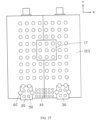
- the battery 100 may further include a fourth adhesion portion 70, and the fourth adhesion portion 70 is provided on a zone 101b of the first surface 101.
- the zone 101b is spaced apart from a zone in which each of the first insulation layer 20 and the second insulation layer 30 is provided in the first surface 101 and the zone 101a in the first surface 101, and the fourth adhesion portion 70 is in contact with neither the first insulation layer 20 nor the second insulation layer 30.
- the zone 101b includes a first section 101b1 and a second section 101b2.
- the first section 101b1 faces away from the zone 101a in the second direction Y
- the second section 101b2 is located on a side of the first insulation layer 20 facing away from the second insulation layer 30 and a side of the second insulation layer 30 facing away from the first insulation layer 20 in the first direction X.
- the fourth adhesion portion 70 is located in a first section 101b1 of the zone 101b.
- the fourth adhesion portion 70 may, for example, at least include but is not limited to one polymer or a mixture formed by a combination of any polymers in cellulose, poly(vinylidene fluoride-co-hexafluoropropylene), poly(vinylidene fluoride-co-trichloroethylene), polymethyl methacrylate, poly butyl acrylate, polyacrylonitrile, polyvinylpyrrolidone, polyvinyl acetate, polyethylene-co-vinyl acetate, polyethylene oxide, polyarylate, cellulose acetate, cellulose acetate butyrate, cellulose acetate propionate, cyanoethyl pullulan, cyanoethyl polyvinyl alcohol, cyanoethyl cellulose, cyanoethyl sucrose, pullulan, carboxymethyl cellulose, and polypropylene-maleic anhydride.
- a shape of the fourth adhesion portion 70 is not limited, and the shape may be a round shape (refer to FIG. 9A ), a rectangular shape (refer to FIG. 14 and FIG. 15 ), a strip shape (refer to FIG. 16 ), another regular or irregular shape, or a combination of these graphics.
- the number of the fourth adhesion portions 70 may also be set as actually needed, and may be one or more.
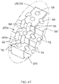
- the battery 100 may include at least two fourth adhesion portions 70 (refer to FIG. 17 ) with different shapes.
- shapes of all the fourth adhesion portions 70 may also be the same.
- the housing 80 further adheres to the electrode assembly 10 through the fourth adhesion portion 70.
- the plurality of fourth adhesion portions 70 may be spaced apart, or adjacent fourth adhesion portions 70 are connected to each other (refer to FIG. 16 ).
- the housing 80 may be further provided with a groove 170', and a portion of the fourth adhesion portion 70 is located in the groove 170'.
- an average area of an orthographic projection of the fourth adhesion portions 70 onto the first surface 101 is set to be greater than an average area of an orthographic projection of the first adhesion portions 40 onto the first surface 101.
- an average area of an orthographic projection of the third adhesion portions 60 onto the first surface 101 is set to be greater than an average area of an orthographic projection of the first adhesion portions 40 onto the first surface 101, and greater than an average area of an orthographic projection of the second adhesion portions 50 onto the first surface 101.
- each of the first insulation layer 20 and the second insulation layer 30 alternatively extends from the first surface 101 to the connection zone 105.
- the first insulation layer 20 and the second insulation layer 30 each extend from the first surface 101 to the second portion 107.
- each of the first insulation layer 20 and the second insulation layer 30 may alternatively extend from the second portion 107 to the second surface 103.
- the first insulation layer 20 and the second insulation layer 30 are provided on the first surface 101 and may separate the electrode assembly 10 from the housing 80, thereby reducing contact between the electrode assembly 10 and the housing 80, reducing a possibility of damaging the housing 80 by the electrode assembly 10, and avoiding damage to the housing caused because an active substance falls off from a zone in which the electrode assembly 10 is integrated with the first insulation layer 20 and the second insulation layer 30.
- the first insulation layer 20 and the second insulation layer 30 may also serve as a buffer between the electrode assembly 10 and the housing 80, thereby reducing a possibility of damage to the housing 80 caused by a sharp point on a surface of the electrode assembly 10.
- the first insulation layer 20 and the second insulation layer 30 may also fasten the electrode assembly 10 and inhibit the electrode assembly 10 from falling loose, thereby reducing a risk of a short circuit between the positive and negative electrodes caused by a movement of a component in the electrode assembly 10 during a dropping process, and improving safety performance of the battery 100.
- an area of projection of the first adhesion portion 40 onto the first surface 101 in the third direction Z perpendicular to the first surface 101 may be less than a total area of an orthographic projection of the first insulation layer 20 and the second insulation layer 30 onto the first surface 101, to help enhance adhesion between the electrode assembly 10 and the housing 80 through the first adhesion portion 40 on the premise that the first insulation layer 20 and the second insulation layer 30 effectively inhibit the electrode assembly 10 from falling loose, thereby improving stability between the electrode assembly 10 and the housing 80, and further improving safety performance of the battery 100.
- a length of the zone 101a in the first direction X may be less than a half of a length of the first surface 101 in the first direction X, to further help enhance adhesion between the electrode assembly 10 and the housing 80 through the first adhesion portion 40 on the premise that the first insulation layer 20 and the second insulation layer 30 effectively inhibit the electrode assembly 10 from falling loose, thereby improving stability between the electrode assembly 10 and the housing 80, and further improving safety performance of the battery 100.
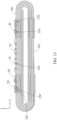
- the electrode assembly 10 may further include a third insulation layer 17, and the third insulation layer 17 is provided on the second surface 103 and fastens to an end of an outermost ring of the electrode assembly 10.
- the outermost ring of the electrode assembly 10 may be a positive electrode plate, a negative electrode plate, or a separator.
- a location for providing the first insulation layer 20 and the second insulation layer 30 is not limited to the foregoing situation.
- the first insulation layer 20 may alternatively extend from the first portion 106 to the first surface 101 but apart from the second portion 107
- the second insulation layer 30 may alternatively extend from the first portion 106 to the first surface 101 but apart from the second portion 107.
- the first surface 101 and the first portion 106 intersect at the second edge 18.
- the first insulation layer 20 may extend from the second edge 18 to the second portion 107 along the first surface 101 but apart from the second portion 107; and the second insulation layer 30 may extend from the second edge 18 to the second portion 107 along the first surface 101 but apart from the second portion 107.
- the first insulation layer 20 extends from the second portion 107 to the first surface 101 but apart from the second portion 106, and the second insulation layer 30 extends from the first portion 106 to the first surface 101 but apart from the second portion 107.
- the first direction X is perpendicular to a direction in which the second portion 107 is located.
- the electrode assembly 10 may also be a stacked structure.
- the fourth adhesion portion 70 may alternatively be provided on the second surface 103 and may alternatively be provided on the third insulation layer 17.
- the first adhesion portion 40, the second adhesion portion 50, and the third adhesion portion 60 may also be provided corresponding to the first insulation layer 20 and the second insulation layer 30 on the second surface 103.
- the method for manufacturing the battery 100 includes the following steps: providing the electrode assembly 10; pasting the first insulation layer 20 and the second insulation layer 30 on the electrode assembly 10; forming the first adhesion portion 40 on a surface of the electrode assembly 10 through a manner including, for example, but not limited to screen printing or dispensing with a spray gun; accommodating, in the housing 80, the electrode assembly 10 provided with the first adhesion portion 40, the first insulation layer 20, the second insulation layer 30, and the third insulation layer 17; and then compressing an outer side of the housing 80, so that the first adhesion portion 40 adheres to an inner side of the housing 80.
- the method for manufacturing the battery 100 may further include: pasting the third insulation layer 17 on the electrode assembly 10 before the first adhesion portion 40 is formed.
- the third insulation layer 17 is pasted on the electrode assembly 10 before the first insulation layer 20 and the second insulation layer 30 are pasted on the electrode assembly 10.
- the method for manufacturing the battery 100 may further include: before the electrode assembly 10 is accommodated in the housing 80, forming the second adhesion portion 50 on a surface of at least one of the first insulation layer 20 and the second insulation layer 30 through the manner including, for example, but not limited to the screen printing or the dispensing with the spray gun. After the outer side of the housing 80 is compressed, the second adhesion portion 50 adheres to the inner side of the housing 80.
- the method for manufacturing the battery 100 may further include: before the electrode assembly 10 is accommodated in the housing 80, forming the third adhesion portion 60 on a surface of at least one of the first insulation layer 20 and the second insulation layer 30 and on the surface of the electrode assembly 10 through the manner including, for example, but not limited to the screen printing or the dispensing with the spray gun. After the outer side of the housing 80 is compressed, the third adhesion portion 60 adheres to the inner side of the housing 80.
- the method for manufacturing the battery 100 may further include: before the electrode assembly 10 is accommodated in the housing 80, forming the fourth adhesion portion 70 on the surface of the electrode assembly 10 through the manner including, for example, but not limited to the screen printing or the dispensing with the spray gun. After the outer side of the housing 80 is compressed, the fourth adhesion portion 70 adheres to the inner side of the housing 80.
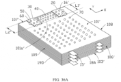
- the stacked electrode assembly 10' is further described by using an example below.
- an electrode assembly 10' is formed by directly stacking a plurality of stacked bodies 10E along a direction Z.
- the electrode assembly 10' includes eight edges perpendicular to the direction Z.
- a first surface 101' is, for example, a zone enclosed by a first edge 16', a third edge 19A, a second edge 18', and a fourth edge 19B that are sequentially connected end to end when viewed in the direction Z shown in FIG. 35A .
- the third edge 19A and the fourth edge 19B are provided opposite each other.
- a second surface 103' is, for example, a zone enclosed by a first edge 16A, a third edge 19C, a second edge 18A, and a fourth edge 19D that are sequentially connected end to end when viewed in the direction Z shown in FIG. 35A .
- the first edge 16A and the second edge 18A are provided opposite each other, and the third edge 19C and the fourth edge 19D are provided opposite each other.
- the first surface 101' and the second surface 103' are provided back away from each other, and are portions of an outer surface of the electrode assembly 10'.
- the outer surface of the electrode assembly 10' further includes a connection zone 105' connecting an edge of the first surface 101' and an edge of the second surface 103'.
- each current collector may be provided with a metal portion 15'.
- the connection zone 105' includes a first portion 106', a third portion 108, a second portion 107', and a fourth portion 109 that are sequentially connected.
- the first portion 106' and the second portion 107' are provided back away from each other.
- the third portion 108 and the fourth portion 109 are provided back away from each other.
- the electrode assembly 10' may further include a metal portion 15', and the metal portion 15' extends from the first portion 106' in a direction back away from the second portion 107'.
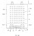
- the first insulation layer 20 and the second insulation layer 30 are both provided on the first surface 101', and the first insulation layer 20 and the second insulation layer 30 are spaced apart along a first direction X.
- the first insulation layer 20 when viewed in the third direction Z, may be, for example, rectangular.
- the first insulation layer 20 may, for example, at least include but is not limited to one or more of polyimide, polyvinyl chloride, polyethylene, and polypropylene.
- the second insulation layer 30 when viewed in the third direction Z, may be, for example, rectangular.
- the second insulation layer 30 may, for example, at least include but is not limited to one or more of polyimide, polyvinyl chloride, polyethylene, and polypropylene.
- the first surface 101' and the second portion 107' intersect at the first edge 16'.
- the first direction X is a direction in which the first edge 16' is located.
- the first insulation layer 20 and the second insulation layer 30 each extend from the first edge 16' along the first surface 101' toward the first portion 106' but do not reach the first portion 106'.
- a length L1' of the first insulation layer 20 extending from the first edge 16' toward the first portion 106' and a length L2' of the second insulation layer 30 extending from the first edge 16' toward the first portion 106' are not particularly limited in a case that the first insulation layer 20 apart from the first portion 106' and the second insulation layer 30 apart from the first portion 106'.
- the length L1' of the first insulation layer 20 extending from the first edge 16' toward the first portion 106' is equal to the length L2' of the second insulation layer 30 extending from the first edge 16' toward the first portion 106'.
- the foregoing length direction is defined as the second direction Y.
- an equal length or width of the two components generally means that a difference between a length or a width of a component and a corresponding length or width of the other component is within ⁇ 3 mm.
- the first insulation layer 20 and the second insulation layer 30 may each include an adhesive layer and a substrate that are laminated.
- the adhesive layer adheres to the substrate and the electrode assembly 10'.
- the adhesive layer may, for example, include but is not limited to at least one of natural rubber, synthetic rubber, acrylate, silica gel, and ethylene-vinyl acetate.
- the substrate may, for example, include but is not limited to at least one of polyethylene, polypropylene, Teflon, polyvinyl chloride, polyimide, and non-woven fabric.
- the first adhesion portion 40 when viewed in the third direction Z perpendicular to the first surface 101', the first adhesion portion 40 is provided on the first surface 101' and located in a zone 101a' between the first insulation layer 20 and the second insulation layer 30. In the second direction Y, the first adhesion portion 40 extends beyond neither the first insulation layer 20 nor the second insulation layer 30.
- a length of the zone 101a' in the first direction X may be less than a half of a length of the first surface 101' in the first direction X.
- an area of an orthographic projection of the first adhesion portion 40 onto the first surface 101' may be less than a total area of an orthographic projection of the first insulation layer 20 and the second insulation layer 30 onto the first surface 101'. Further, in some embodiments, the area of the orthographic projection of the first adhesion portion 40 onto the first surface 101' may be less than an area of an orthographic projection of the first insulation layer 20 onto the first surface 101', and may also be less than an area of an orthographic projection of the second insulation layer 30 onto the first surface 101'.
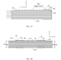
- a first distance H1 from at least a part of an overlapped zone of the first surface 101' and the first insulation layer 20 to the second surface 103' is less than a second distance H2 from the first adhesion portion 40 to the second surface 103'.
- first distance H1 is less than the second distance H2
- distances from different locations in the at least a part of the overlapped zone of the first surface 101' and the first insulation layer 20 to the second surface 103' may be different.
- the first distance H1 from a corresponding bottom portion of the first insulation layer 20 on the first surface 101' to the second surface 103' is less than the second distance H2 from the first adhesion portion 40 to the second surface 103'.
- a first recess 120 is provided on the first surface 101', and the first recess 120 is such provided that it extends from the first edge 16' toward the first portion 106'. At least a portion of the first insulation layer 20 further away from the first portion 106' is provided in the first recess 120.
- the first recess 120 may be an inclined groove whose depth gradually decreases from the first edge 16' toward the first portion 106' along the second direction Y A portion of the first insulation layer 20 close to the first portion 106' may be located outside the first recess 120.
- a third distance H3 from at least a part of an overlapped zone of the first surface 101' and the second insulation layer 30 to the second surface 103' is less than the second distance H2.
- distances from different locations in the at least a part of an overlapped zone of the first surface 101' and the second insulation layer 30 to the second surface 103' may be different.
- the third distance H3 from a corresponding button portion of the second insulation layer 30 on the first surface 101' to the second surface 103' is less than the second distance H2.
- a second recess 130 is provided on the first surface 101', and the second recess 130 is such provided that it extends from the first edge 16' toward the first portion 106'. At least a portion of the second insulation layer 30 further away from the first portion 106' is provided in the second recess 130.
- the second recess 130 may be an inclined groove whose depth gradually decreases from the first edge 16' toward the first portion 106' along the second direction Y A portion of the second insulation layer 30 close to the first portion 106' may be located outside the second recess 130.
- the first distance H1 may be equal to the third distance H3. In some embodiments, the first distance H1 may not be equal to the third distance H3.
- the first surface 101' may be provided with a first groove 140, and the first adhesion portion 40 is located in the first groove 140.
- first adhesion portions 40 there are a plurality of first grooves 140, and each first adhesion portion 40 is located in one first groove 140.
- the shape When viewed in the third direction Z, neither a shape nor a size of the first adhesion portion 40 is limited, and the shape may be a round shape (refer to FIG. 36B ), a rectangular shape (refer to FIG. 14 and FIG. 15 ), a strip shape (refer to FIG. 16 ), another regular or irregular shape, or a combination of these graphics.
- the number of the first adhesion portions 40 may also be set as actually needed, and may be one or more. When there are a plurality of first adhesion portions 40, the plurality of first adhesion portions 40 are spaced apart (for example, arranged into a dot array).
- the battery 100 When viewed in the third direction Z, the battery 100 may include at least two first adhesion portions 40 (refer to FIG.
- first adhesion portions 40 may also be the same.
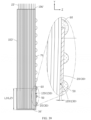
- the battery 100 may further include a housing 80.
- the housing 80 may be, for example, but is not limited to, one or more of an aluminum-plastic film, a heat shrinkable film, an aluminum housing, and a steel housing.
- the housing 80 encloses the electrode assembly 10', the first insulation layer 20, and the second insulation layer 30, and adheres to the electrode assembly 10' through the first adhesion portion 40 (refer to both FIG. 43 and FIG. 44 ).
- the housing 80 may be provided with a groove 140', and a portion of the first adhesion portion 40 is located in the groove 140'.
- the first adhesion portion 40 is provided in the zone 101a' between the first insulation layer 20 and the second insulation layer 30, so that compression degrees of a zone in which each of the first insulation layer 20 and the second insulation layer 30 is provided in the battery 100 and a zone corresponding to the zone 101a' in the battery during chemical conversion are more uniform in a horizontal direction (that is, along the first direction X and the second direction Y), thereby helping reduce a deformation degree of the battery 100 during use.
- Providing the first adhesion portion 40 between the first insulation layer 20 and the second insulation layer 30 may increase an adhesion force between the electrode assembly 10' and the housing 80, to suppress relative displacement between the electrode assembly 10' and the housing 80 when the battery 100 is subject to an external force, thereby further reducing a possibility of damage to the battery 100 due to the external force and prolonging service life of the battery 100.
- the first adhesion portion 40 adheres to the housing 80 and the electrode assembly 10', thereby further helping suppress deformation of the electrode assembly 10'.
- a shape of the first adhesion portion 40 after adhesion to the housing 80 may change.
- the plurality of first adhesion portions 40 may be spaced apart, or adjacent first adhesion portions 40 are connected to each other (refer to FIG. 16 ).
- the battery 100 may further include a second adhesion portion 50, and the second adhesion portion 50 is provided on a surface 21 of the first insulation layer 20 facing away from the second surface 103'.
- An area of an orthographic projection of the second adhesion portion 50 onto the first surface 101' is smaller than an area of an orthographic projection of the first insulation layer 20 onto the first surface 101'.
- a surface 31 of the second insulation layer 30 facing away from the second surface 103' may also be provided with the second adhesion portion 50.
- an area of an orthographic projection of the second adhesion portion 50 onto the first surface 101' is smaller than an area of an orthographic projection of the second insulation layer 30 onto the first surface 101'.
- the second adhesion portion 50 may, for example, at least include but is not limited to one polymer or a mixture formed by a combination of any polymers in cellulose, poly(vinylidene fluoride-co-hexafluoropropylene), poly(vinylidene fluoride-co-trichloroethylene), polymethyl methacrylate, poly butyl acrylate, polyacrylonitrile, polyvinylpyrrolidone, polyvinyl acetate, polyethylene-co-vinyl acetate, polyethylene oxide, polyarylate, cellulose acetate, cellulose acetate butyrate, cellulose acetate propionate, cyanoethyl pullulan, cyanoethyl polyvinyl alcohol, cyanoethyl cellulose, cyanoethyl sucrose, pullulan, carboxymethyl cellulose, and polypropylene-maleic anhydride.
- a shape of the second adhesion portion 50 is not limited, and the shape may be a round shape, a rectangular shape, a strip shape, another regular or irregular shape, or a combination of these graphics.
- the number of the second adhesion portions 50 may also be set as actually needed, and may be one or more.
- the battery 100 may include at least two second adhesion portions 50 with different shapes. In some embodiments, when viewed in the third direction Z, shapes of all the second adhesion portions 50 may also be the same.
- a surface of the first insulation layer 20 facing away from the second surface 103' is provided with a second groove 150, and the second adhesion portion 50 is located in the second groove 150.
- the housing 80 adheres to the first insulation layer 20 through the second adhesion portion 50.
- the housing 80 may alternatively adhere to the second insulation layer 30 through the second adhesion portion 50.
- the housing 80 may alternatively adhere to the first insulation layer 20 and the second insulation layer 30 through the second adhesion portion 50.
- the plurality of second adhesion portions 50 may be spaced apart, or adjacent second adhesion portions 50 are connected to each other.
- the housing 80 may be further provided with a groove 150', and a portion of the second adhesion portion 50 is located in the groove 150'.
- the battery 100 may further include a third adhesion portion 60, and the third adhesion portion 60 is provided on a surface 21 of the first insulation layer 20 facing away from the second surface 103', and extends across an intersection zone of the first insulation layer 20 and the first surface 101' to the first surface 101'.
- the third adhesion portion 60 may, for example, at least include but is not limited to one polymer or a mixture formed by a combination of any polymers in cellulose, poly(vinylidene fluoride-co-hexafluoropropylene), poly(vinylidene fluoride-co-trichloroethylene), polymethyl methacrylate, poly butyl acrylate, polyacrylonitrile, polyvinylpyrrolidone, polyvinyl acetate, polyethylene-co-vinyl acetate, polyethylene oxide, polyarylate, cellulose acetate, cellulose acetate butyrate, cellulose acetate propionate, cyanoethyl pullulan, cyanoethyl polyvinyl alcohol, cyanoethyl cellulose, cyanoethyl sucrose, pullulan, carboxymethyl cellulose, and polypropylene-maleic anhydride.
- the third adhesion portion 60 adheres to the housing 80.
- the housing 80 may adhere to the first insulation layer 20 through the third adhesion portion 60.
- the housing 80 may alternatively adhere to the second insulation layer 30 through the third adhesion portion 60.
- the housing 80 may alternatively adhere to both the first insulation layer 20 and the second insulation layer 30 through the third adhesion portion 60.
- the housing 80 may be further provided with a groove 160', and a portion of the third adhesion portion 60 is located in the groove 160'.
- the battery 100 may further include a fourth adhesion portion 70, and the fourth adhesion portion 70 is provided on a zone 101b' of the first surface 101'.
- the zone 101b' is spaced apart from a zone in which each of the first insulation layer 20 and the second insulation layer 30 is provided in the first surface 101' and the zone 101a' of the first surface 101', and the fourth adhesion portion 70 is in contact with neither the first insulation layer 20 nor the second insulation layer 30.
- the zone 101b' includes a first section 101b1' and a second section 101b2'.
- the first section 101b1' faces away from the zone 101a' in the second direction Y
- the second section 101b2' is located on a side of the first insulation layer 20 facing away from the second insulation layer 30 and a side of the second insulation layer 30 facing away from the first insulation layer 20 in the first direction X.
- the fourth adhesion portion 70 is located in a first section 101b1' of the zone 101b'.
- the fourth adhesion portion 70 may, for example, at least include but is not limited to one polymer or a mixture formed by a combination of any polymers in cellulose, poly(vinylidene fluoride-co-hexafluoropropylene), poly(vinylidene fluoride-co-trichloroethylene), polymethyl methacrylate, poly butyl acrylate, polyacrylonitrile, polyvinylpyrrolidone, polyvinyl acetate, polyethylene-co-vinyl acetate, polyethylene oxide, polyarylate, cellulose acetate, cellulose acetate butyrate, cellulose acetate propionate, cyanoethyl pullulan, cyanoethyl polyvinyl alcohol, cyanoethyl cellulose, cyanoethyl sucrose, pullulan, carboxymethyl cellulose, and polypropylene-maleic anhydride.
- a shape of the fourth adhesion portion 70 is not limited, and the shape may be a round shape (refer to FIG. 36B ), a rectangular shape (refer to FIG. 14 and FIG. 15 ), a strip shape (refer to FIG. 16 ), another regular or irregular shape, or a combination of these graphics.
- the number of the fourth adhesion portions 70 may also be set as actually needed, and may be one or more.
- the battery 100 may include at least two fourth adhesion portions 70 (refer to FIG. 17 ) with different shapes.
- shapes of all the fourth adhesion portions 70 may also be the same.
- the housing 80 further adheres to the electrode assembly 10' through the fourth adhesion portion 70.
- the plurality of fourth adhesion portions 70 may be spaced apart, or adjacent fourth adhesion portions 70 are connected to each other (refer to FIG. 16 ).
- the housing 80 may be further provided with a groove 170', and a portion of the fourth adhesion portion 70 is located in the groove 170'.
- each of the first insulation layer 20 and the second insulation layer 30 alternatively extends from the first surface 101' to the connection zone 105'.
- the first insulation layer 20 and the second insulation layer 30 each extend from the first surface 101' to the second portion 107'.
- each of the first insulation layer 20 and the second insulation layer 30 may alternatively extend from the second portion 107' to the second surface 103'.
- the first insulation layer 20 and the second insulation layer 30 are provided on the first surface 101' and may separate the electrode assembly 10' from the housing 80, thereby reducing contact between the electrode assembly 10' and the housing 80, reducing a possibility of damaging the housing 80 by the electrode assembly 10', and avoiding damage to the housing caused because an active substance falls off from a zone in which the electrode assembly 10' is integrated with the first insulation layer 20 and the second insulation layer 30.
- the first insulation layer 20 and the second insulation layer 30 may also serve as a buffer between the electrode assembly 10' and the housing 80, thereby reducing a possibility of damage to the housing 80 caused by a sharp point on a surface of the electrode assembly 10'.
- the first insulation layer 20 and the second insulation layer 30 may also fasten the electrode assembly 10' and inhibit the electrode assembly 10' from falling loose.
- a location for providing the first insulation layer 20 and the second insulation layer 30 is not limited to the foregoing situation.
- the first insulation layer 20 may alternatively extend from the first portion 106' to the first surface 101' but apart from the second portion 107'
- the second insulation layer 30 may alternatively extend from the first portion 106' to the first surface 101' but apart from the second portion 107'.
- the first surface 101' and the first portion 106' intersect at the second edge 18'.
- the first insulation layer 20 may extend from the second edge 18' to the second portion 107' along the first surface 101' but apart from the second portion 107'; and the second insulation layer 30 may extend from the second edge 18' to the second portion 107' along the first surface 101' but apart from the second portion 107'.
- the first insulation layer 20 extends from the second portion 107' to the first surface 101' but apart from the first portion 106', and the second insulation layer 30 extends from the first portion 106' to the first surface 101' but apart from the second portion 107'.
- the first direction X is perpendicular to a direction in which the second portion 107' is located.
- the fourth adhesion portion 70 may alternatively be provided on the second surface 103'.
- the first adhesion portion 40, the second adhesion portion 50, and the third adhesion portion 60 may also be provided corresponding to the first insulation layer 20 and the second insulation layer 30 on the second surface 103'.
- the first insulation layer 20 may alternatively extend from the third portion 108 to the first surface 101' but apart from the fourth portion 109
- the second insulation layer 30 may alternatively extend from the fourth portion 109 to the first surface 101' but apart from the third portion 108.
- the first surface 101' and the third portion 108 intersect at the third edge 19A
- the first surface 101' and the fourth portion 109 intersect at the fourth edge 19B.
- the first insulation layer 20 may extend from the third edge 19A to the fourth portion 109 along the first surface 101' but apart from the fourth portion 109; and the second insulation layer 30 may extend from the fourth edge 19B to the third portion 108 along the first surface 101' but apart from the third portion 108.
- first insulation layer 20 there may be one first insulation layer 20, or there may be a plurality of spaced first insulation layers 20, and a size of the first insulation layer 20 may be set as needed.
- the plurality of first insulation layers 20 and/or the plurality of second insulation layers 30 are all applicable to the electrode assembly 10 of a winding structure.
- one first insulation layer 20 and one second insulation layer 30 each may alternatively extend from the third portion 108 to the first surface 101' but do not reach the fourth portion 109.
- Another first insulation layer 20 and another second insulation layer 30 each may alternatively extend from the fourth portion 109 to the first surface 101' but do not reach the third portion 108.
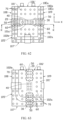
- the metal portion 15' includes a plurality of first metal portions 151 and a plurality of second metal portions 153.
- the first metal portion 151 is provided on the first portion 106', and the second metal portion 153 is provided on the second portion 107'.
- the first metal portion 151 and the second metal portion 153 may be provided and spaced apart on the second portion 107'.
- the first metal portion 151 is provided on the first portion 106', and the second metal portion 153 is provided on the second portion 107', and both are applicable to the electrode assembly 10 of a winding structure.
- the first insulation layer 20 may alternatively extend from the first portion 106' to the second portion 107' across the first surface 101', and the second insulation layer 30 may alternatively extend from the first portion 106' to the second portion 107' across the first surface 101'.
- the first insulation layer 20 may alternatively extend from the first portion 106' to the second surface 103', and may alternatively extend from the second portion 107' to the second surface 103'; and the second insulation layer 30 may alternatively extend from the first portion 106' to the second surface 103', and may alternatively extend from the second portion 107' to the second surface 103'.
- first insulation layer 20 may alternatively be ring-shaped and the first surface 101', the first portion 106', the second surface 103', and the second portion 107' are sleeved with the first insulation layer 20; and the second insulation layer 30 may alternatively be ring-shaped and the first surface 101', the first portion 106', the second surface 103', and the second portion 107' are sleeved with the second insulation layer 30.
- first insulation layer 20 may alternatively extend from the third portion 108 to the fourth portion 109 across the first surface 101'
- the second insulation layer 30 may alternatively extend from the third portion 108 to the fourth portion 109 across the first surface 101'.
- first insulation layer 20 may alternatively extend from the third portion 108 to the second surface 103', and may alternatively extend from the fourth portion 109 to the second surface 103'; and the second insulation layer 30 may alternatively extend from the third portion 108 to the second surface 103', and may alternatively extend from the fourth portion 109 to the second surface 103'.
- first insulation layer 20 may alternatively be ring-shaped and the first surface 101', the third portion 108, the second surface 103', and the fourth portion 109 are sleeved with the first insulation layer 20; and the second insulation layer 30 may alternatively be ring-shaped and the first surface 101', the third portion 108, the second surface 103', and the fourth portion 109 are sleeved with the second insulation layer 30.
- first insulation layer 20 and the second insulation layer 30 in FIG. 60 are both applicable to the electrode assembly 10 of a winding structure.
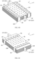
- the battery assembly 10 is formed by stacking a plurality of stacked bodies 10E of different sizes along the third direction Z.
- the battery assembly 10 is formed by sequentially stacking a first stacked body 10Ea, a second stacked body 10Eb, and a third stacked body 10Ec along the third direction Z whose sizes increase sequentially.
- a surface of the first stacked body 10Ea is the first surface 101'
- a portion of the second stacked body 10Eb uncovered by the first stacked body 10Ea is a first step face 102a
- a portion of the third stacked body 10Ec uncovered by the second stacked body 10Eb is a second step face 102b
- a surface of the third stacked body 10Ec facing away from the first surface 101' is the second surface 103'.
- the connection zone 105' includes the first step face 102a and the second step face 102b.
- the first portion 106' is a surface provided along the direction Z.
- the second portion 107', the third portion 108, and the fourth portion 109 are step-shaped and respectively include a portion of the first step face 102a and a portion of the second step face 102b.
- the first insulation layer 20 is provided on the first surface 101' and may extend from the first surface 101' to the first step face 102a and the second step face 102b corresponding to the third portion 108. Further, the first insulation layer 20 may continue to extend from the second step face 102b corresponding to the third portion 108 to the second surface 103'.
- the second insulation layer 30 is provided on the first surface 101' and may extend from the first surface 101' to the first step face 102a and the second step face 102b corresponding to the fourth portion 109. Further, the second insulation layer 30 may continue to extend from the second step face 102b corresponding to the fourth portion 109 to the second surface 103'. As shown in FIG. 64 and FIG.
- none of the second adhesion portion 50, the third adhesion portion 60, and the fourth adhesion portion 70 provided corresponding to the first step face 102a extends beyond the first stacked body 10Ea in the direction Z
- none of the second adhesion portion 50, the third adhesion portion 60, and the fourth adhesion portion 70 provided corresponding to the second step face 102b extends beyond the second stacked body 10Eb in the direction Z.
- a second adhesion portion 50 that is provided corresponding to the first step face 102a and that extends to the first surface 101'
- a second adhesion portion 50 that is provided corresponding to the second step face 102b and that extends to the first step face 102a
- a third adhesion portion 60 and a fourth adhesion portion 70 that are provided corresponding to the first step face 102a and that extend to the first surface 101'
- a third adhesion portion 60 and a fourth adhesion portion 70 that are provided corresponding to the second step face 102b and that extend to the first step face 102a.
- the third adhesion portion 60 helps enhance firmness of adhesion between the insulation layer and the electrode assembly.
- the first portion 106' and the fourth portion 109 are surfaces provided along the direction Z.
- the second portion 107' and the third portion 108 are step-shaped and respectively include a portion of the first step face 102a and a portion of the second step face 102b.
- the first insulation layer 20 is provided on the first surface 101' and may extend from the first surface 101' to the first portion 106'. Further, the first insulation layer 20 may continue to extend from the first portion 106' to the second surface 103'.
- the second insulation layer 30 is provided on the first surface 101' and may extend from the first surface 101' to the first step face 102a and the second step face 102b corresponding to the second portion 107'.
- the second insulation layer 30 may continue to extend from the second step face 102b corresponding to the second portion 107' to the second surface 103'.
- none of the second adhesion portion 50, the third adhesion portion 60, and the fourth adhesion portion 70 provided corresponding to the first step face 102a extends beyond the first stacked body 10Ea in the direction Z
- none of the second adhesion portion 50, the third adhesion portion 60, and the fourth adhesion portion 70 provided corresponding to the second step face 102b extends beyond the second stacked body 10Eb in the direction Z.
- a surface of an electrode assembly was provided with no adhesion portion.
- a first insulation layer and a second insulation layer were provided on the electrode assembly.
- the first insulation layer and the second insulation layer respectively extended from a first surface to a second surface across a second portion to fasten the electrode assembly.
- a housing (aluminum-plastic film) accommodated the electrode assembly and was fastened to the electrode assembly through an adhesion portion.
- the battery was obtained after the electrolyte was injected and the housing was sealed. After the battery was subject to chemical conversion treatment and a standard charge and discharge process, the battery was subject to capacity activation, and finally preparation of the battery was completed after degassing treatment.
- Comparative Example 2 a difference between Comparative Example 2 and Comparative Example 1 was that an adhesion portion was provided in a first zone on a side of the first insulation layer and the second insulation layer that faced away from a second portion on the first surface of the electrode assembly.
- Example 1 a difference between Example 1 and Comparative Example 2 was that an adhesion portion was also provided in a second zone on the first surface of the electrode assembly in addition to a zone in which each of the first insulation layer and the second insulation layer was provided and the first zone, that is, the second zone included a zone between the first insulation layer and the second insulation layer, a zone on a side of the first insulation layer away from the second insulation layer, and a zone on a side of the second insulation layer away from the first insulation layer.
- Example 2 a difference between Example 2 and Example 1 was that an adhesion portion was also provided in an intersection zone of a surface of the first insulation layer away from the first surface and the first surface, the surface of the first insulation layer away from the first surface, an intersection zone of a surface of the second insulation layer away from the first surface and the first surface, and the surface of the second insulation layer away from the first surface.
- Example 3 a difference between Example 3 and Comparative Example 2 was that an adhesion portion was further provided in a zone, on the first surface of the electrode assembly, between the first insulation layer and the second insulation layer.
- Example 4 a difference between Example 4 and Comparative Example 1 was that an adhesion portion was only provided in a zone, on the first surface of the electrode assembly, between the first insulation layer and the second insulation layer.
- the batteries in Comparative Examples 1 and 2 and Examples 1 to 4 were charged with a current of 0.2C at room temperature, and thicknesses of the batteries were measured after full charging; then the batteries were discharged to a cut-off voltage, and then the batteries were charged to a limit voltage with a current of 0.8C at a constant current and a constant voltage, and then thicknesses of zones of the batteries were measured and used as initial thicknesses (herein, referring to FIG.
- the batteries were cyclically charged and discharged 700 times with 0.8C/1C, and after 700 cycles, the thicknesses of the foregoing zones were measured again, that is, the thicknesses after the cycles, and the difference between D3 and D1 or the difference ⁇ D between D3 and D2 was calculated and recorded in Table 1 below.
- the first insulation layer and the second insulation layer may suppress swelling of the battery.
- a deformation amount of a battery with the adhesion portion provided between the first insulation layer and the second insulation layer was significantly less than a deformation amount of the battery with no adhesion portion provided between the first insulation layer and the second insulation layer.
- the two back-away surfaces that connected the first portion (that is, a head) to the second portion (that is, a bottom) in the connection zone of the electrode assembly were defined as the third portion and the fourth portion respectively.
- the batteries in Comparative Examples 1 and 2 and Examples 1 to 4 were charged to the limit voltage with a current of 0.2C at room temperature, the batteries were subject to a drop test, and details were:
- the battery was fastened in a battery-dedicated drop test box with a dedicated adhesive, a robot arm grabbed the drop test box containing the battery and released the drop test box to drop the battery onto a marble slab at a height of 1.8 m in a preset drop method, the preset drop method was six rounds of dropping in a sequence of the first surface facing down->the second surface facing down ⁇ the first portion facing down ⁇ the third portion facing down ⁇ the second portion facing down->the fourth portion facing down.
- provision of the adhesion portion in the zone between the first insulation layer and the second insulation layer better helped alleviate drop failure of the battery compared with no provision of the adhesion portion, which better helped improve safety of the battery.
- the provision of the first insulation layer and the second insulation layer, and the adhesion portion could alleviate the drop failure of the battery, which helped improve safety of the battery.
- the first insulation layer and the second insulation layer are provided on the surface of the electrode assembly, and the first adhesion portion is provided between the first insulation layer and the second insulation layer.
- the first adhesion portion adheres to the electrode assembly and the housing, to help reduce the damage caused by the electrode assembly to the housing and help protect the electrode assembly when the battery is subject to an external force, thereby improving the safety of the battery and prolonging the service life of the battery.
Landscapes
- Chemical & Material Sciences (AREA)
- Chemical Kinetics & Catalysis (AREA)
- Electrochemistry (AREA)
- General Chemical & Material Sciences (AREA)
- Engineering & Computer Science (AREA)
- Manufacturing & Machinery (AREA)
- Secondary Cells (AREA)
- Materials Engineering (AREA)
- Cell Separators (AREA)
- Connection Of Batteries Or Terminals (AREA)
Abstract
Description
- This application relates to a battery.
- As consumer electronic products, electric vehicles, and the like are maturely used, customers are paying increasing attention to risks in whole product applications. For example, high impact resistance is required for electronic products. As an important component of electronic products, batteries are also subject to an impact resistance requirement. For a battery, when an electronic product is impacted, an electrode assembly accommodated in a housing of the battery is prone to damage the housing, or the electrode assembly is damaged due to the impact, thereby affecting safety and service life of the battery.
- In view of the foregoing situation, it is necessary to provide a battery that helps improve impact resistance performance, to further improve safety.
- This application provides a battery, including an electrode assembly, a first insulation layer, a second insulation layer, and at least one first adhesion portion. The electrode assembly includes a first surface and a second surface provided back away from the first surface. The first insulation layer is provided on the first surface. The second insulation layer is provided on the first surface and spaced apart from the first insulation layer. The first adhesion portion is provided on the first surface and located in a zone between the first insulation layer and the second insulation layer.
- In a solution of this application, the battery includes two or more first adhesion portions, and the two or more first adhesion portions are arranged into a dot array.
- In a solution of this application, the battery further includes a second adhesion portion provided on a side of the first insulation layer facing away from the first surface.
- In a solution of this application, an area of an orthographic projection of the second adhesion portion onto the first surface is smaller than an area of an orthographic projection of the first insulation layer onto the first surface.
- In a solution of this application, the battery includes at least two second adhesion portions, and the at least two second adhesion portions are arranged into a dot array.
- In a solution of this application, the first insulation layer extends from the first surface to the second surface, and the second insulation layer extends from the first surface to the second surface.
- In a solution of this application, a metal portion is further provided at an end of the electrode assembly, and the first insulation layer and the second insulation layer are located at an end of the electrode assembly away from the metal portion.
- In a solution of this application, an area of an orthographic projection of the at least one first adhesion portion onto the first surface is smaller than a total area of an orthographic projection of the first insulation layer and the second insulation layer onto the first surface.
- In a solution of this application, the area of the an orthographic projection of the at least one first adhesion portion onto the first surface is smaller than an area of an orthographic projection of the first insulation layer onto the first surface, and is smaller than an area of an orthographic projection of the second insulation layer onto the first surface.
- In a solution of this application, a distance from a part of a zone of the first surface in which the first surface is in contact with the first insulation layer to the second surface is a first distance, a distance from the first adhesion portion to the second surface is a second distance, and the first distance is less than the second distance.
- In a solution of this application, a distance from a part of a zone of the first surface in which the first surface is in contact with the second insulation layer to the second surface is a third distance, and the third distance is less than the second distance.
- In a solution of this application, the first distance and the third distance are unequal.
- In a solution of this application, a length of the first adhesion portion in a first direction is less than a half of a length of the first surface in the first direction.
- In a solution of this application, the first surface is provided with a first groove corresponding to the first adhesion portion, and the first adhesion portion is located in the first groove.
- In a solution of this application, a surface of the first insulation layer corresponding to the second adhesion portion is provided with a second groove, and the second adhesion portion is located in the second groove.
- In a solution of this application, the battery further includes a third adhesion portion provided on a surface of the first insulation layer facing away from the second surface, and the third adhesion portion extends to a zone of the first surface that is not provided with the first insulation layer.
- In a solution of this application, the battery further includes a fourth adhesion portion, the fourth adhesion portion is provided on the first surface, a zone of the first surface that is provided with the fourth adhesion portion is spaced apart from a zone of the first surface that is provided with the first insulation layer and the second insulation layer and a zone of the first surface that is located between the first insulation layer and the second insulation layer, and the fourth adhesion portion is in contact with neither the first insulation layer nor the second insulation layer.
- In a solution of this application, the electrode assembly includes at least two fourth adhesion portions with different orthographic projection shapes, and the fourth adhesion portions are arranged into a dot array.
- In a solution of this application, the electrode assembly further includes a third insulation layer, the electrode assembly is of a winding structure, and the third insulation layer is provided on the second surface and fastened to an end of an outermost electrode plate of the electrode assembly.
- In a solution of this application, the battery further includes a housing, and the housing encloses the electrode assembly, the first insulation layer, and the second insulation layer, and adheres to the electrode assembly through the first adhesion portion.
- In a solution of this application, an average area of an an orthographic projection of the fourth adhesion portions onto the first surface is greater than an average area of an orthographic projection of the first adhesion portions onto the first surface.
- In a solution of this application, an average area of an orthographic projection of the third adhesion portions onto the first surface is greater than an average area of an orthographic projection of the first adhesion portions onto the first surface and greater than an average area of an orthographic projection of the second adhesion portions onto the first surface.
- Based on the battery according to this application, the first insulation layer and the second insulation layer are provided on the surface of the electrode assembly, and the first adhesion portion is provided between the first insulation layer and the second insulation layer. When the housing encloses the electrode assembly, the first adhesion portion adheres to the electrode assembly and the housing, thereby improving safety of the battery and prolonging service life of the battery when the battery is subject to an external force.
-
-
FIG. 1 is a schematic structural diagram of a battery according to an embodiment of this application; -
FIG. 2 is a side view of a battery according to an embodiment of this application; -
FIG. 3 is a schematic structural diagram of a stacked body according to an embodiment of this application; -
FIG. 4 is a schematic structural diagram of a first conductive layer according to an embodiment of this application; -
FIG. 5 is a schematic structural diagram of a second conductive layer according to an embodiment of this application; -
FIG. 6 is a schematic structural diagram of an electrode assembly according to an embodiment of this application; -
FIG. 7 is a schematic structural diagram of an electrode assembly according to an embodiment of this application; -
FIG. 8 is a schematic structural diagram of a battery according to an embodiment of this application; -
FIG. 9A is a front view of a battery according to an embodiment of this application; -
FIG. 9B is a front view of a battery according to an embodiment of this application; -
FIG. 10 is a schematic cross-sectional diagram of a battery in a first direction according to an embodiment of this application; -
FIG. 11 is a schematic cross-sectional diagram of a battery in a second direction according to an embodiment of this application; -
FIG. 12 is a schematic cross-sectional diagram of a battery in a first direction according to an embodiment of this application; -
FIG. 13 is a schematic cross-sectional diagram of a battery in a first direction according to an embodiment of this application; -
FIG. 14 is a schematic structural diagram of a first adhesion portion or a fourth adhesion portion according to an embodiment of this application; -
FIG. 15 is a schematic structural diagram of a first adhesion portion or a fourth adhesion portion according to an embodiment of this application; -
FIG. 16 is a schematic structural diagram of a first adhesion portion or a fourth adhesion portion according to an embodiment of this application; -
FIG. 17 is a schematic structural diagram of a first adhesion portion or a fourth adhesion portion according to an embodiment of this application; -
FIG. 18 is a schematic structural diagram of a battery according to an embodiment of this application; -
FIG. 19 is a schematic partial exploded view of a battery according to an embodiment of this application; -
FIG. 20A is a schematic partial cross-sectional diagram of a battery in a second direction according to an embodiment of this application; -
FIG. 20B is a schematic partial cross-sectional diagram of a battery in a second direction according to an embodiment of this application; -
FIG. 21A is a schematic partial cross-sectional diagram of a battery in a second direction according to an embodiment of this application; -
FIG. 21B is a schematic partial cross-sectional diagram of a battery in a second direction according to an embodiment of this application; -
FIG. 22 is a side view of a battery according to an embodiment of this application; -
FIG. 23 is a rear view of a battery according to an embodiment of this application; -
FIG. 24 is a bottom view of a battery according to an embodiment of this application; -
FIG. 25 is a schematic structural diagram of a battery according to an embodiment of this application; -
FIG. 26 is a schematic structural diagram of a battery according to an embodiment of this application; -
FIG. 27 is a bottom view of a battery according to an embodiment of this application; -
FIG. 28 is a schematic partial structural diagram of a battery according to Comparative Example 2 in this application; -
FIG. 29 is a schematic partial structural diagram of a battery according to Comparative Example 3 in this application; -
FIG. 30 is a schematic partial structural diagram of a battery according to Example 1 in this application; -
FIG. 31 is a schematic partial structural diagram of a battery according to Example 2 in this application; -
FIG. 32 is a schematic partial structural diagram of a battery according to Example 3 in this application; -
FIG. 33 is a schematic partial structural diagram of a battery according to Example 4 in this application; -
FIG. 34 is a schematic structural diagram of a battery according to an example of this application; -
FIG. 35A is a schematic structural diagram of a battery according to an embodiment of this application; -
FIG. 35B is a schematic structural diagram of a battery according to an embodiment of this application; -
FIG. 36A is a schematic structural diagram of a battery according to an embodiment of this application; -
FIG. 36B is a front view of a battery according to an embodiment of this application; -
FIG. 36C is a front view of a battery according to an embodiment of this application; -
FIG. 37 is a side view of a battery according to an embodiment of this application; -
FIG. 38 is a schematic cross-sectional diagram of a battery in a first direction according to an embodiment of this application; -
FIG. 39 is a schematic cross-sectional diagram of a battery in a second direction according to an embodiment of this application; -
FIG. 40 is a schematic cross-sectional diagram of a battery in a first direction according to an embodiment of this application; -
FIG. 41 is a schematic cross-sectional diagram of a battery in a first direction according to an embodiment of this application; -
FIG. 42 is a schematic partial exploded view of a battery according to an embodiment of this application; -
FIG. 43 is a schematic partial cross-sectional diagram of a battery in a second direction according to an embodiment of this application; -
FIG. 44 is a schematic partial cross-sectional diagram of a battery in a second direction according to an embodiment of this application; -
FIG. 45 is a schematic partial cross-sectional diagram of a battery in a second direction according to an embodiment of this application; -
FIG. 46 is a schematic partial cross-sectional diagram of a battery in a second direction according to an embodiment of this application; -
FIG. 47 is a side view of a battery according to an embodiment of this application; -
FIG. 48 is a schematic structural diagram of a battery according to an embodiment of this application; -
FIG. 49 is a schematic structural diagram of a battery according to an embodiment of this application; -
FIG. 50 is a bottom view of a battery according to an embodiment of this application; -
FIG. 51 is a bottom view of a battery according to an embodiment of this application; -
FIG. 52 is a schematic structural diagram of a battery according to an embodiment of this application; -
FIG. 53 is a schematic structural diagram of a battery according to an embodiment of this application; -
FIG. 54A is a schematic structural diagram of a battery according to an embodiment of this application; -
FIG. 54B is a schematic structural diagram of a battery according to an embodiment of this application; -
FIG. 55 is a schematic structural diagram of a battery according to an embodiment of this application; -
FIG. 56 is a schematic structural diagram of a battery according to an embodiment of this application; -
FIG. 57 is a schematic structural diagram of a battery according to an embodiment of this application; -
FIG. 58 is a schematic structural diagram of a battery according to an embodiment of this application; -
FIG. 59 is a schematic structural diagram of a battery according to an embodiment of this application; -
FIG. 60 is a schematic structural diagram of a battery according to an embodiment of this application; -
FIG. 61 is a schematic structural diagram of a battery according to an embodiment of this application; -
FIG. 62 is a schematic structural diagram of a battery according to an embodiment of this application; -
FIG. 63 is a schematic structural diagram of a battery according to an embodiment of this application; -
FIG. 64 is a partially enlarged schematic diagram of a battery according to an embodiment of this application; -
FIG. 65A is a schematic cross-sectional diagram of a battery in a K-K direction inFIG. 62 according to an embodiment of this application; -
FIG. 65B is a schematic cross-sectional diagram of a battery according to an embodiment of this application; -
FIG. 66 is a partially enlarged schematic diagram of a battery according to an embodiment of this application; and -
FIG. 67 is a partially enlarged schematic diagram of a battery according to an embodiment of this application. - Reference signs of main components:
Battery 100 Electrode assembly 10, 10' First insulation layer 20 Second insulation layer 30 First adhesion portion 40 First surface 101, 101' Second surface 103, 103' Connection zone 105, 105' Electrode plate 11 First end 101A Second end 101B First conductive layer 10A First isolation layer 10B Second conductive layer 10C Second isolation layer 10D Surface 10a, 10b, 10c, 21, 31 Stacked body 10E, 10Ea Current collector 10AA, 10CA Active substance layer 10AB, 10CB First portion 106, 106' First section 101b1, 101b1' Second portion 107, 107' Second section 101b2, 101b2' Third portion 108 Fourth portion 109 Metal portion 15, 15' First metal portion 151 Second metal portion 153 Third edge 19A Fourth edge 19B First direction X First edge 16, 16', 16A Second direction Y Gap zone 101a, 101a' First recess 120 Second recess 130 First groove 140 Third direction Z Housing 80 Second adhesion portion 50 Second groove 150 Third adhesion portion 60 Fourth adhesion portion 70 Zone 101b, 101b' Second edge 18, 18', 18A Third edge 19A, 19C Fourth edge 19B, 19D Third insulation layer 17 Groove 140', 150', 160', 170' First step face 102a Second step face 102b - This application will be further described with reference to the accompanying drawings in the following specific embodiments.
- The following clearly describes the technical solutions in the embodiments of this application in detail. Apparently, the described embodiments are merely some but not all of the embodiments of this application. Unless otherwise defined, all technical and scientific terms used herein shall have the same meanings as commonly understood by persons skilled in the art to which this application belongs. The terms used in this specification of this application are only used to describe specific embodiments, and are not intended to limit this application.
- The following describes embodiments of this application in detail. However, this application may be embodied in many different forms, and should not be construed as being limited to the exemplary embodiments illustrated herein. Instead, these exemplary embodiments are provided, so that this application may be thoroughly conveyed to a person skilled in the art in detail.
- In addition, for brevity and clarity, in drawings, a size or a thickness of each component and layer may be enlarged. Through the specification, a same number refers to a same element. As used herein, the term "and/or" includes any one and all of combinations of one or more related listed items. In addition, it should be understood that when an element A is described to be "connected to" an element B, the element A may be directly connected to the element B, or there may be an intermediate element C that indirectly connects the element A with the element B.
- Further, when "may" is used for describing the embodiments of this application, "one or more embodiments of this application" may be indicated.
- The terminology used herein is intended to describe specific embodiments rather than impose a limitation on this application. As used herein, unless otherwise clearly stated in the context, a singular form is intended to also include a plural form. It should be further understood that when used in this specification, the term "include" means presence of the described feature, numerical value, step, operation, element and/or component, but does not exclude the presence or addition of one or more other features, numerical values, steps, operations, elements, components, and/or a combination thereof.
- A space-related term such as "on" may be used herein for ease of description of a relationship between an element or feature and another element (a plurality of elements) or feature (a plurality of features) as illustrated in the figure. It should be understood that, in addition to the direction illustrated in the figure, the space-related term is intended to include different directions during use or operation of a device or an apparatus. For example, if the device in the figure is turned over, an element described to be "over" or "on" another element or feature is to be at an direction "under" or "beneath" said another element or feature. Therefore, the example term "on" may include directions of "over" and "beneath". It should be understood that although the terms first, second, third, and the like may be used herein to describe various elements, components, zones, layers, and/or portions, these elements, components, zones, layers and/or portions, which are not subject to a limitation by the terms. These terms are used to distinguish an element, component, zone, layer or portion from another element, component, zone, layer, or portion. Therefore, the first element, component, zone, layer, or portion described below may be referred to as the second element, component, zone, layer, or portion without departing from teachings of the exemplary embodiments. In this application, the first direction may be any direction in a plane in which the first surface is located.
- The following describes some embodiments of this application in detail. In absence of conflicts, the following embodiments and features in the embodiments may be combined.
- Referring to
FIG. 1 , abattery 100 includes anelectrode assembly 10, afirst insulation layer 20, asecond insulation layer 30, and afirst adhesion portion 40. - Referring to
FIG. 1 , theelectrode assembly 10 includes afirst surface 101, asecond surface 103 provided back away from thefirst surface 101, and aconnection zone 105 connecting thefirst surface 101 and thesecond surface 103. - Referring to
FIG. 1 , theelectrode assembly 10 includes anelectrode plate 11 and a separator (not shown), and theelectrode plate 11 and the separator are wound to form a winding structure. Thefirst surface 101, thesecond surface 103, and theconnection zone 105 serve as a portion of an outer surface of theelectrode assembly 10. - For example,
FIG. 1 shows a structure formed by winding theelectrode assembly 10 a plurality of times. In this case, theelectrode assembly 10 has a plurality of bent portions in a direction, that is, a direction X in the figure, and the plurality of bent portions are respectively distributed on opposite sides of a center of thebattery 100 in the direction X, that is, left and right sides inFIG. 1 . A connection zone between an outer plane of theelectrode assembly 10 and an end of a bent portion on an outermost side of a left side of a center of thebattery 100 that is closest to the center of thebattery 100 is afirst end 101A; and a connection zone between the outer plane of theelectrode assembly 10 and an end of a bent portion on an outermost side of a right side of the center of thebattery 100 that is closest to the center of thebattery 100 is asecond end 101B. - In this embodiment, the
first surface 101 is, for example, a zone enclosed by thefirst end 101A, thesecond end 101B, and two ends of theelectrode assembly 10 in a direction Y, that is, afirst edge 16 and asecond edge 18 when viewed in a direction Z shown inFIG. 1 . - For example, for a
stacked electrode assembly 10 formed by stacking theelectrode plate 11 and the separator in the direction Z, theelectrode assembly 10 includes four edges perpendicular to the direction Z, and a zone enclosed by the four edges is thesecond surface 103. - The
electrode assembly 10 is further described by using an example below. - Referring to
FIG. 3 , thebattery assembly 10 may include: a firstconductive layer 10A, afirst isolation layer 10B, a secondconductive layer 10C, and asecond isolation layer 10D. Thefirst isolation layer 10B is formed on asurface 10a of the firstconductive layer 10A. The secondconductive layer 10C is formed on asurface 10b of thefirst isolation layer 10B away from the firstconductive layer 10A. Thesecond isolation layer 10D is formed on asurface 10c of the secondconductive layer 10C facing away from thefirst isolation layer 10B. In this way, astacked body 10E may be formed, and theelectrode assembly 10 may be formed on the basis of thestacked body 10E. - Referring to
FIG. 3 and FIG. 4 , when viewed in a direction perpendicular to thesurface 10a, the firstconductive layer 10A may be, for example, rectangular. The firstconductive layer 10A may be, for example, formed by stacking a current collector 10AA and an active substance layer 10AB. The current collector 10AA may, for example, at least include but is not limited to one or more of conductive metal thin plates such as an aluminum mesh and aluminum foil. The active substance layer 10AB may, for example, at least include but is not limited to one or more of lithium cobalt oxide, lithium nickel cobalt manganate, lithium nickel cobalt aluminate, lithium manganate oxide, lithium nickel oxide, lithium manganese iron phosphate, lithium vanadium phosphate, lithium vanadyl phosphate, lithium iron phosphate, lithium titanate, and a lithium-rich manganese-based material. The firstconductive layer 10A may, for example, serve as a positive electrode plate to form theelectrode assembly 10 of thebattery 100. - Referring to
FIG. 3 , when viewed in a direction perpendicular to thesurface 10b, thefirst isolation layer 10B may be, for example, rectangular. Thefirst isolation layer 10B may, for example, at least include but is not limited to at least one or more of polyethylene, polypropylene, polyethylene terephthalate, polyimide, and aramid. Thefirst isolation layer 10B may, for example, serve as a separator to form theelectrode assembly 10 of thebattery 100. - Referring to
FIG. 3 and FIG. 5 , when viewed in a direction perpendicular to thesurface 10c, the secondconductive layer 10C may be, for example, rectangular. The secondconductive layer 10C may be, for example, formed by stacking a current collector 10CA and an active substance layer 10CB. The current collector 10CA may, for example, at least include but is not limited to one or two of conductive metal thin plates such as nickel foil and copper foil. The active substance layer 10CB may, for example, at least include but is not limited to one or more of graphite, soft carbon, hard carbon, graphene, a meso-carbon microbead, a silicon-based material, a tin-based material, lithium titanate, or another metal that may form an alloy with lithium. The secondconductive layer 10C may, for example, serve as a negative electrode plate to form theelectrode assembly 10 of thebattery 100. - When viewed in a direction perpendicular to the
surface 10b, thesecond isolation layer 10D may be, for example, rectangular. Thesecond isolation layer 10D may, for example, at least include but is not limited to at least one or more of polyethylene, polypropylene, polyethylene terephthalate, polyimide, and aramid. Thesecond isolation layer 10D may, for example, serve as a separator to form theelectrode assembly 10 of thebattery 100. - Referring to
FIG. 6 , theelectrode assembly 10 may be, for example, formed by winding a stacked body 10Ea formed by stacking a plurality ofstacked bodies 10E. Alternatively, for example, referring toFIG. 7 , theelectrode assembly 10 may be formed by directly stacking a plurality ofstacked bodies 10E along the direction Z. - In this embodiment, the outer surface of the
electrode assembly 10 includes thefirst surface 101 and thesecond surface 103 facing away from thefirst surface 101. In addition, the outer surface of theelectrode assembly 10 further includes theconnection zone 105 perpendicular to thefirst surface 101 in the third direction Z. - In this embodiment, the
second surface 103 is, for example, a zone corresponding to a plane of theelectrode assembly 10 back away from thefirst surface 101 and a zone enclosed by thefirst end 101A, thesecond end 101B, and the two ends of theelectrode assembly 10 in the direction Y, that is, thefirst edge 16 and thesecond edge 18, when viewed in the direction Z shown inFIG. 1 . - Referring to
FIG. 1 andFIG. 8 , theconnection zone 105 includes afirst portion 106 and asecond portion 107 back away from thefirst portion 106. Theelectrode assembly 10 may further include ametal portion 15, and themetal portion 15 is provided on thefirst portion 106. An end of themetal portion 15 is connected to theelectrode plate 11, and the other end may be connected to another electronic component, to implement feasible electrical connectivity between theelectrode assembly 10 and said electronic component. - The
first insulation layer 20 and thesecond insulation layer 30 are both provided on thefirst surface 101, and thefirst insulation layer 20 and thesecond insulation layer 30 are spaced apart along the first direction X. - In this embodiment, when viewed in the third direction Z, the
first insulation layer 20 may be, for example, rectangular. Thefirst insulation layer 20 may, for example, at least include but is not limited to one or more of polyimide, polyvinyl chloride, polyethylene, and polypropylene. When viewed in the third direction Z, thesecond insulation layer 30 may be, for example, rectangular. Thesecond insulation layer 30 may, for example, at least include but is not limited to one or more of polyimide, polyvinyl chloride, polyethylene, and polypropylene. - The
first surface 101 and thesecond portion 107 intersect at thefirst edge 16. In some embodiments, the first direction X is a direction in which thefirst edge 16 is located. When viewed in the third direction Z, thefirst insulation layer 20 and thesecond insulation layer 30 each extend from thefirst edge 16 along thefirst surface 101 toward thefirst portion 106 but do not reach thefirst portion 106. - A length L1 of the
first insulation layer 20 extending from thefirst edge 16 toward thefirst portion 106 and a length L2 of thesecond insulation layer 30 extending from thefirst edge 16 toward thefirst portion 106 are not particularly limited in a case that thefirst insulation layer 20 apart from thefirst portion 106 and thesecond insulation layer 30 apart from thefirst portion 106. In this embodiment, the length L1 of thefirst insulation layer 20 extending from thefirst edge 16 toward thefirst portion 106 is equal to the length L2 of thesecond insulation layer 30 extending from thefirst edge 16 toward thefirst portion 106. In this case, the foregoing length direction is defined as the second direction Y - The
first insulation layer 20 and thesecond insulation layer 30 may each include an adhesive layer and a substrate that are laminated. The adhesive layer adheres to the substrate and theelectrode assembly 10. The adhesive layer may, for example, at least include but is not limited to at least one or more of natural rubber, synthetic rubber, acrylate, silica gel, and ethylene-vinyl acetate. The substrate may, for example, at least include but is not limited to at least one or more of polyethylene, polypropylene, Teflon, polyvinyl chloride, polyimide, and non-woven fabric. - Referring to
FIG. 1, FIG. 2 , andFIG. 9A , when viewed in the third direction Z perpendicular to thefirst surface 101, thefirst adhesion portion 40 is provided on thefirst surface 101 and located in azone 101a between thefirst insulation layer 20 and thesecond insulation layer 30. In the second direction Y, thefirst adhesion portion 40 extends beyond neither thefirst insulation layer 20 nor thesecond insulation layer 30. In some embodiments, a length of thezone 101a in the first direction X may be less than a half of a length of thefirst surface 101 in the first direction X. - In some embodiments, an area of an orthographic projection of the
first adhesion portion 40 onto thefirst surface 101, that is, an area of projection of thefirst adhesion portion 40 onto thefirst surface 101 along the third direction Z perpendicular to thefirst surface 101, may be less than a total area of an orthographic projection of thefirst insulation layer 20 and thesecond insulation layer 30 onto thefirst surface 101. Further, in some embodiments, the area of the orthographic projection of thefirst adhesion portion 40 onto thefirst surface 101 may be less than an area of an orthographic projection of thefirst insulation layer 20 onto thefirst surface 101, and may also be less than an area of an orthographic projection of thesecond insulation layer 30 onto thefirst surface 101. Thefirst adhesion portion 40 may, for example, at least include but is not limited to one polymer or a mixture formed by a combination of any polymers in cellulose, poly(vinylidene fluoride-co-hexafluoropropylene), poly(vinylidene fluoride-co-trichloroethylene), polymethyl methacrylate, poly butyl acrylate, polyacrylonitrile, polyvinylpyrrolidone, polyvinyl acetate, polyethylene-co-vinyl acetate, polyethylene oxide, polyarylate, cellulose acetate, cellulose acetate butyrate, cellulose acetate propionate, cyanoethyl pullulan, cyanoethyl polyvinyl alcohol, cyanoethyl cellulose, cyanoethyl sucrose, pullulan, carboxymethyl cellulose, and polypropylene-maleic anhydride. - Referring to
FIG. 10 , a first distance H1 from at least a part of an overlapped zone of thefirst surface 101 and thefirst insulation layer 20 to thesecond surface 103 is less than a second distance H2 from thefirst adhesion portion 40 to thesecond surface 103. On the premise of ensuring that the first distance H1 is less than the second distance H2, distances from different locations in the at least a part of an overlapped zone of thefirst surface 101 and thefirst insulation layer 20 to thesecond surface 103 may be different. Further, referring toFIG. 1 ,FIG. 9A , andFIG. 10 , herein, in the at least a part of an overlapped zone of thefirst edge 16 and thefirst insulation layer 20, the first distance H1 from a corresponding bottom portion of thefirst insulation layer 20 on thefirst surface 101 to thesecond surface 103 is less than the second distance H2 from thefirst adhesion portion 40 to thesecond surface 103. - Specifically, referring to
FIG. 11 , afirst recess 120 is provided on thefirst surface 101, and thefirst recess 120 is such provided that it extends from thefirst edge 16 toward thefirst portion 106. At least a portion of thefirst insulation layer 20 further away from thefirst portion 106 is provided in thefirst recess 120. In this embodiment, thefirst recess 120 may be an inclined groove whose depth gradually decreases from thefirst edge 16 toward thefirst portion 106 along the second direction Y A portion of thefirst insulation layer 20 close to thefirst portion 106 may be located outside thefirst recess 120. - Referring to
FIG. 1 ,FIG. 9A , andFIG. 10 , a third distance H3 from at least a part of an overlapped zone of thefirst surface 101 and thesecond insulation layer 30 to thesecond surface 103 is less than the second distance H2. On the premise of ensuring that the third distance H3 is less than the second distance H2, distances from different locations in the at least a part of an overlapped zone of thefirst surface 101 and thesecond insulation layer 30 to thesecond surface 103 may be different. Further, herein, in the at least a part of an overlapped zone of thefirst edge 16 and thesecond insulation layer 30, the third distance H3 from a corresponding bottom portion of thesecond insulation layer 30 on thefirst surface 101 to thesecond surface 103 is less than the second distance H2. - Referring to
FIG. 11 , asecond recess 130 is provided on thefirst surface 101, and thesecond recess 130 is such provided that it extends from thefirst edge 16 toward thefirst portion 106. At least a portion of thesecond insulation layer 30 further away from thefirst portion 106 is provided in thesecond recess 130. In this embodiment, thesecond recess 130 may be an inclined groove whose depth gradually decreases from thefirst edge 16 toward thefirst portion 106 along the second direction Y A portion of thesecond insulation layer 30 close to thefirst portion 106 may be located outside thesecond recess 130. - In some embodiments, referring to
FIG. 12 , the first distance H1 may not be equal to the third distance H3. - Referring to
FIG. 13 , thefirst surface 101 may be provided with afirst groove 140, and thefirst adhesion portion 40 is located in thefirst groove 140. In this embodiment, there are a plurality offirst adhesion portions 40, there are a plurality offirst grooves 140, and eachfirst adhesion portion 40 is located in onefirst groove 140. - When viewed in the third direction Z, neither a shape nor a size of the
first adhesion portion 40 is limited, and the shape may be a round shape (refer toFIG. 9A ), a rectangular shape (refer toFIG. 14 and FIG. 15 ), a strip shape (refer toFIG. 16 ), another regular or irregular shape, or a combination of these graphics. The number of thefirst adhesion portions 40 may also be set as actually needed, and may be one or more. When there are a plurality offirst adhesion portions 40, the plurality offirst adhesion portions 40 are spaced apart (for example, arranged into a dot array). When viewed in the third direction Z, thebattery 100 may include at least two first adhesion portions 40 (refer toFIG. 17 ) with different shapes, or may include at least twofirst adhesion portions 40 of different sizes (refer toFIG. 9B ). In some embodiments, referring toFIG. 9A , when viewed in the third direction Z, shapes of all thefirst adhesion portions 40 may also be the same. - Referring to
FIG. 18 andFIG. 19 , thebattery 100 may further include ahousing 80. Thehousing 80 may be, for example, but is not limited to, one or more of an aluminum-plastic film, a heat shrinkable film, an aluminum housing, and a steel housing. Thehousing 80 encloses theelectrode assembly 10, thefirst insulation layer 20, and thesecond insulation layer 30, and adheres to theelectrode assembly 10 through the first adhesion portion 40 (refer to bothFIG. 20A andFIG. 20B ). In some embodiments, as shown inFIG. 20B , thehousing 80 may be provided with a groove 140', and a portion of thefirst adhesion portion 40 is located in the groove 140'. Thefirst adhesion portion 40 is provided in thezone 101a between thefirst insulation layer 20 and thesecond insulation layer 30, so that compression degrees of a zone in which each of thefirst insulation layer 20 and thesecond insulation layer 30 is provided in thebattery 100 and a zone corresponding to thezone 101a in the battery during chemical conversion are more uniform in a horizontal direction, that is, along the first direction X and the second direction Y, thereby helping reduce a deformation degree of thebattery 100 during use. Providing thefirst adhesion portion 40 between thefirst insulation layer 20 and thesecond insulation layer 30 may increase an adhesion force between theelectrode assembly 10 and thehousing 80, to suppress relative displacement between theelectrode assembly 10 and thehousing 80 when thebattery 100 is subject to an external force, thereby further reducing a possibility of damage to thebattery 100 due to the external force and prolonging service life of thebattery 100. In addition, because thefirst adhesion portion 40 adheres to thehousing 80 and theelectrode assembly 10, thereby further helping suppress deformation of theelectrode assembly 10. In addition, a shape of thefirst adhesion portion 40 after adhesion to thehousing 80 may change. When there are a plurality offirst adhesion portions 40, after the plurality offirst adhesion portions 40 adhere to thehousing 80, the plurality offirst adhesion portions 40 may be spaced apart, or adjacentfirst adhesion portions 40 are connected to each other (refer toFIG. 16 ). When the plurality offirst adhesion portions 40 are arranged into a dot array, an arrangement of thefirst adhesion portion 40 is more flexible, a location for providing thefirst adhesion portion 40 may be more accurate, and thicknesses after adhesion of thefirst adhesion portions 40 to thehousing 80 may be more consistent. - Referring to
FIG. 1, FIG. 2 ,FIG. 9A , andFIG. 10 , thebattery 100 may further include asecond adhesion portion 50, and thesecond adhesion portion 50 is provided on asurface 21 of thefirst insulation layer 20 facing away from thesecond surface 103. An area of an orthographic projection of thesecond adhesion portion 50 onto thefirst surface 101 is less than an area of an orthographic projection of thefirst insulation layer 20 onto thefirst surface 101. Asurface 31 of thesecond insulation layer 30 facing away from thesecond surface 103 may also be provided with thesecond adhesion portion 50. In this case, an area of an orthographic projection of thesecond adhesion portion 50 onto thefirst surface 101 is less than an area of an orthographic projection of thesecond insulation layer 30 onto thefirst surface 101. - The
second adhesion portion 50 may, for example, at least include but is not limited to one polymer or a mixture formed by a combination of any polymers in cellulose, poly(vinylidene fluoride-co-hexafluoropropylene), poly(vinylidene fluoride-co-trichloroethylene), polymethyl methacrylate, poly butyl acrylate, polyacrylonitrile, polyvinylpyrrolidone, polyvinyl acetate, polyethylene-co-vinyl acetate, polyethylene oxide, polyarylate, cellulose acetate, cellulose acetate butyrate, cellulose acetate propionate, cyanoethyl pullulan, cyanoethyl polyvinyl alcohol, cyanoethyl cellulose, cyanoethyl sucrose, pullulan, carboxymethyl cellulose, and polypropylene-maleic anhydride. - When viewed in the third direction Z, a shape of the
second adhesion portion 50 is not limited, and the shape may be a round shape, a rectangular shape, a strip shape, another regular or irregular shape, or a combination of these graphics. The number of thesecond adhesion portions 50 may also be set as actually needed, and may be one or more. When there are a plurality ofsecond adhesion portions 50, the plurality ofsecond adhesion portions 50 are spaced apart (for example, arranged into a dot array). When viewed in the third direction Z, thebattery 100 may include at least twosecond adhesion portions 50 with different shapes. In some embodiments, when viewed in the third direction Z, shapes of all thesecond adhesion portions 50 may also be the same. - In some embodiments, referring to
FIG. 13 , a surface of thefirst insulation layer 20 facing away from thesecond surface 103 is provided with asecond groove 150, and thesecond adhesion portion 50 is located in thesecond groove 150. - Referring to
FIG. 18 ,FIG. 21A , andFIG. 21B , thehousing 80 adheres to thefirst insulation layer 20 through thesecond adhesion portion 50, which facilitates stability between theelectrode assembly 10 and thehousing 80. Thehousing 80 may alternatively adhere to thesecond insulation layer 30 through thesecond adhesion portion 50, which facilitates the stability between theelectrode assembly 10 and thehousing 80. Thehousing 80 may alternatively adhere to thefirst insulation layer 20 and thesecond insulation layer 30 through thesecond adhesion portion 50. Thesecond adhesion portion 50 avoids direct adhesion to theelectrode assembly 10. During a drop process of thebattery 100, thesecond adhesion portion 50 adheres to thehousing 80 and thefirst insulation layer 20, or adheres to thehousing 80 and thesecond insulation layer 30 instead of thehousing 80 and theelectrode assembly 10, the area of the orthographic projection of thesecond adhesion portion 50 onto thefirst surface 101 is less than the area of the orthographic projection of thefirst insulation layer 20 or thesecond insulation layer 30 onto thefirst surface 101 that adheres to thesecond adhesion portion 50, that is, a contact area between thefirst insulation layer 20 or thesecond insulation layer 30 and theelectrode assembly 10 is larger, and therefore, a pulling force of thehousing 80 on theelectrode assembly 10 through thesecond adhesion portion 50 is dispersed, thereby reducing a probability of damage caused by pulling theelectrode assembly 10, and reducing a risk of a short circuit between the positive and negative electrodes caused thereby. When there are a plurality ofsecond adhesion portions 50, after the plurality ofsecond adhesion portions 50 adhere to thehousing 80, the plurality ofsecond adhesion portions 50 may be spaced apart, or adjacentsecond adhesion portions 50 are connected to each other. When the plurality ofsecond adhesion portions 50 are arranged into a dot array, an arrangement of thesecond adhesion portion 50 is more flexible, a location for providing thesecond adhesion portion 50 may be more accurate, and thicknesses after adhesion of thesecond adhesion portions 50 to thehousing 80 may be more consistent. In some embodiments, as shown inFIG. 21B , thehousing 80 may be further provided with a groove 150', and a portion of thesecond adhesion portion 50 is located in the groove 150'. - Referring to
FIG. 1, FIG. 2 , andFIG. 9A , thebattery 100 may further include athird adhesion portion 60, and thethird adhesion portion 60 is provided on asurface 21 of thefirst insulation layer 20 facing away from thesecond surface 103, and extends across an intersection zone of thefirst insulation layer 20 and thefirst surface 101 to thefirst surface 101. - The
third adhesion portion 60 may, for example, at least include but is not limited to one polymer or a mixture formed by a combination of any polymers in cellulose, poly(vinylidene fluoride-co-hexafluoropropylene), poly(vinylidene fluoride-co-trichloroethylene), polymethyl methacrylate, poly butyl acrylate, polyacrylonitrile, polyvinylpyrrolidone, polyvinyl acetate, polyethylene-co-vinyl acetate, polyethylene oxide, polyarylate, cellulose acetate, cellulose acetate butyrate, cellulose acetate propionate, cyanoethyl pullulan, cyanoethyl polyvinyl alcohol, cyanoethyl cellulose, cyanoethyl sucrose, pullulan, carboxymethyl cellulose, and polypropylene-maleic anhydride. - Referring to
FIG. 18 ,FIG. 21A andFIG. 21B , thethird adhesion portion 60 adheres to thehousing 80. Thehousing 80 may adhere to thefirst insulation layer 20 through thethird adhesion portion 60. Thehousing 80 may alternatively adhere to thesecond insulation layer 30 through thethird adhesion portion 60. Thehousing 80 may alternatively adhere to both thefirst insulation layer 20 and thesecond insulation layer 30 through thethird adhesion portion 60. In some embodiments, as shown inFIG. 21B , thehousing 80 may be further provided with a groove 160', and a portion of thethird adhesion portion 60 is located in the groove 160'. - Referring to
FIG. 1, FIG. 2 ,FIG. 9A ,FIG. 21A , andFIG. 21B , thebattery 100 may further include afourth adhesion portion 70, and thefourth adhesion portion 70 is provided on azone 101b of thefirst surface 101. Thezone 101b is spaced apart from a zone in which each of thefirst insulation layer 20 and thesecond insulation layer 30 is provided in thefirst surface 101 and thezone 101a in thefirst surface 101, and thefourth adhesion portion 70 is in contact with neither thefirst insulation layer 20 nor thesecond insulation layer 30. - Specifically, referring to
FIG. 9A , thezone 101b includes a first section 101b1 and a second section 101b2. The first section 101b1 faces away from thezone 101a in the second direction Y The second section 101b2 is located on a side of thefirst insulation layer 20 facing away from thesecond insulation layer 30 and a side of thesecond insulation layer 30 facing away from thefirst insulation layer 20 in the first direction X. In this embodiment, thefourth adhesion portion 70 is located in a first section 101b1 of thezone 101b. - The
fourth adhesion portion 70 may, for example, at least include but is not limited to one polymer or a mixture formed by a combination of any polymers in cellulose, poly(vinylidene fluoride-co-hexafluoropropylene), poly(vinylidene fluoride-co-trichloroethylene), polymethyl methacrylate, poly butyl acrylate, polyacrylonitrile, polyvinylpyrrolidone, polyvinyl acetate, polyethylene-co-vinyl acetate, polyethylene oxide, polyarylate, cellulose acetate, cellulose acetate butyrate, cellulose acetate propionate, cyanoethyl pullulan, cyanoethyl polyvinyl alcohol, cyanoethyl cellulose, cyanoethyl sucrose, pullulan, carboxymethyl cellulose, and polypropylene-maleic anhydride. - When viewed in the third direction Z, a shape of the
fourth adhesion portion 70 is not limited, and the shape may be a round shape (refer toFIG. 9A ), a rectangular shape (refer toFIG. 14 and FIG. 15 ), a strip shape (refer toFIG. 16 ), another regular or irregular shape, or a combination of these graphics. The number of thefourth adhesion portions 70 may also be set as actually needed, and may be one or more. When there are a plurality offourth adhesion portions 70, the plurality offourth adhesion portions 70 are spaced apart (for example, arranged into a dot array). When viewed in the third direction Z, thebattery 100 may include at least two fourth adhesion portions 70 (refer toFIG. 17 ) with different shapes. In some embodiments, when viewed in the third direction Z, shapes of all thefourth adhesion portions 70 may also be the same. - Referring to
FIG. 18 ,FIG. 21A , andFIG. 21B , thehousing 80 further adheres to theelectrode assembly 10 through thefourth adhesion portion 70. When there are a plurality offourth adhesion portions 70, after the plurality offourth adhesion portions 70 adhere to thehousing 80, the plurality offourth adhesion portions 70 may be spaced apart, or adjacentfourth adhesion portions 70 are connected to each other (refer toFIG. 16 ). In some embodiments, as shown inFIG. 21B , thehousing 80 may be further provided with a groove 170', and a portion of thefourth adhesion portion 70 is located in the groove 170'. - In an embodiment, in order that the shear stress between the
electrode assembly 10 and thehousing 80 concentrates on the first section 101b1 instead of thegap zone 101a during dropping, so as to prevent a failure of thebattery 100 due to a short circuit between the positive and negative electrodes that is caused when the electrode plate in thegap zone 101a is torn or severely pulled, an average area of an orthographic projection of thefourth adhesion portions 70 onto thefirst surface 101 is set to be greater than an average area of an orthographic projection of thefirst adhesion portions 40 onto thefirst surface 101. - In an embodiment, in order that the
first insulation layer 20 or thesecond insulation layer 30 adheres to thefirst surface 101 tighter, so as to prevent thefirst insulation layer 20 or thesecond insulation layer 30 from falling off under the shear stress when the battery is dropped, an average area of an orthographic projection of thethird adhesion portions 60 onto thefirst surface 101 is set to be greater than an average area of an orthographic projection of thefirst adhesion portions 40 onto thefirst surface 101, and greater than an average area of an orthographic projection of thesecond adhesion portions 50 onto thefirst surface 101. - Referring to
FIG. 2 ,FIG. 21A andFIG. 22 , each of thefirst insulation layer 20 and thesecond insulation layer 30 alternatively extends from thefirst surface 101 to theconnection zone 105. In this embodiment, thefirst insulation layer 20 and thesecond insulation layer 30 each extend from thefirst surface 101 to thesecond portion 107. Further, each of thefirst insulation layer 20 and thesecond insulation layer 30 may alternatively extend from thesecond portion 107 to thesecond surface 103. Thefirst insulation layer 20 and thesecond insulation layer 30 are provided on thefirst surface 101 and may separate theelectrode assembly 10 from thehousing 80, thereby reducing contact between theelectrode assembly 10 and thehousing 80, reducing a possibility of damaging thehousing 80 by theelectrode assembly 10, and avoiding damage to the housing caused because an active substance falls off from a zone in which theelectrode assembly 10 is integrated with thefirst insulation layer 20 and thesecond insulation layer 30. In addition, when thebattery 100 is dropped, thefirst insulation layer 20 and thesecond insulation layer 30 may also serve as a buffer between theelectrode assembly 10 and thehousing 80, thereby reducing a possibility of damage to thehousing 80 caused by a sharp point on a surface of theelectrode assembly 10. In addition, when thefirst insulation layer 20 and thesecond insulation layer 30 extend to thesecond portion 107 and even thesecond surface 103, thefirst insulation layer 20 and thesecond insulation layer 30 may also fasten theelectrode assembly 10 and inhibit theelectrode assembly 10 from falling loose, thereby reducing a risk of a short circuit between the positive and negative electrodes caused by a movement of a component in theelectrode assembly 10 during a dropping process, and improving safety performance of thebattery 100. In this case, further, an area of projection of thefirst adhesion portion 40 onto thefirst surface 101 in the third direction Z perpendicular to thefirst surface 101 may be less than a total area of an orthographic projection of thefirst insulation layer 20 and thesecond insulation layer 30 onto thefirst surface 101, to help enhance adhesion between theelectrode assembly 10 and thehousing 80 through thefirst adhesion portion 40 on the premise that thefirst insulation layer 20 and thesecond insulation layer 30 effectively inhibit theelectrode assembly 10 from falling loose, thereby improving stability between theelectrode assembly 10 and thehousing 80, and further improving safety performance of thebattery 100. Further, a length of thezone 101a in the first direction X may be less than a half of a length of thefirst surface 101 in the first direction X, to further help enhance adhesion between theelectrode assembly 10 and thehousing 80 through thefirst adhesion portion 40 on the premise that thefirst insulation layer 20 and thesecond insulation layer 30 effectively inhibit theelectrode assembly 10 from falling loose, thereby improving stability between theelectrode assembly 10 and thehousing 80, and further improving safety performance of thebattery 100. - Referring to
FIG. 23 and FIG. 24 , theelectrode assembly 10 may further include athird insulation layer 17, and thethird insulation layer 17 is provided on thesecond surface 103 and fastens to an end of an outermost ring of theelectrode assembly 10. The outermost ring of theelectrode assembly 10 may be a positive electrode plate, a negative electrode plate, or a separator. - In some embodiments, a location for providing the
first insulation layer 20 and thesecond insulation layer 30 is not limited to the foregoing situation. For example, referring toFIG. 25 , thefirst insulation layer 20 may alternatively extend from thefirst portion 106 to thefirst surface 101 but apart from thesecond portion 107, and thesecond insulation layer 30 may alternatively extend from thefirst portion 106 to thefirst surface 101 but apart from thesecond portion 107. Thefirst surface 101 and thefirst portion 106 intersect at thesecond edge 18. Further, when viewed in the third direction Z, thefirst insulation layer 20 may extend from thesecond edge 18 to thesecond portion 107 along thefirst surface 101 but apart from thesecond portion 107; and thesecond insulation layer 30 may extend from thesecond edge 18 to thesecond portion 107 along thefirst surface 101 but apart from thesecond portion 107. For another example, referring toFIG. 26 , thefirst insulation layer 20 extends from thesecond portion 107 to thefirst surface 101 but apart from thesecond portion 106, and thesecond insulation layer 30 extends from thefirst portion 106 to thefirst surface 101 but apart from thesecond portion 107. In this case, the first direction X is perpendicular to a direction in which thesecond portion 107 is located. In some embodiments, theelectrode assembly 10 may also be a stacked structure. - In some embodiments, referring to
FIG. 24 andFIG. 27 , thefourth adhesion portion 70 may alternatively be provided on thesecond surface 103 and may alternatively be provided on thethird insulation layer 17. When thefirst insulation layer 20 and thesecond insulation layer 30 extend to thesecond surface 103, thefirst adhesion portion 40, thesecond adhesion portion 50, and thethird adhesion portion 60 may also be provided corresponding to thefirst insulation layer 20 and thesecond insulation layer 30 on thesecond surface 103. - The method for manufacturing the
battery 100 includes the following steps: providing theelectrode assembly 10; pasting thefirst insulation layer 20 and thesecond insulation layer 30 on theelectrode assembly 10; forming thefirst adhesion portion 40 on a surface of theelectrode assembly 10 through a manner including, for example, but not limited to screen printing or dispensing with a spray gun; accommodating, in thehousing 80, theelectrode assembly 10 provided with thefirst adhesion portion 40, thefirst insulation layer 20, thesecond insulation layer 30, and thethird insulation layer 17; and then compressing an outer side of thehousing 80, so that thefirst adhesion portion 40 adheres to an inner side of thehousing 80. - The method for manufacturing the
battery 100 may further include: pasting thethird insulation layer 17 on theelectrode assembly 10 before thefirst adhesion portion 40 is formed. Preferably, thethird insulation layer 17 is pasted on theelectrode assembly 10 before thefirst insulation layer 20 and thesecond insulation layer 30 are pasted on theelectrode assembly 10. - The method for manufacturing the
battery 100 may further include: before theelectrode assembly 10 is accommodated in thehousing 80, forming thesecond adhesion portion 50 on a surface of at least one of thefirst insulation layer 20 and thesecond insulation layer 30 through the manner including, for example, but not limited to the screen printing or the dispensing with the spray gun. After the outer side of thehousing 80 is compressed, thesecond adhesion portion 50 adheres to the inner side of thehousing 80. - The method for manufacturing the
battery 100 may further include: before theelectrode assembly 10 is accommodated in thehousing 80, forming thethird adhesion portion 60 on a surface of at least one of thefirst insulation layer 20 and thesecond insulation layer 30 and on the surface of theelectrode assembly 10 through the manner including, for example, but not limited to the screen printing or the dispensing with the spray gun. After the outer side of thehousing 80 is compressed, thethird adhesion portion 60 adheres to the inner side of thehousing 80. - The method for manufacturing the
battery 100 may further include: before theelectrode assembly 10 is accommodated in thehousing 80, forming thefourth adhesion portion 70 on the surface of theelectrode assembly 10 through the manner including, for example, but not limited to the screen printing or the dispensing with the spray gun. After the outer side of thehousing 80 is compressed, thefourth adhesion portion 70 adheres to the inner side of thehousing 80. - The stacked electrode assembly 10' is further described by using an example below.
- Referring to
FIG. 7 , different from the electrode assembly 10Ea (as shown inFIG. 6 ) formed by stacking and windingstacked bodies 10E, an electrode assembly 10' is formed by directly stacking a plurality ofstacked bodies 10E along a direction Z. - Referring to
FIG. 35A , the electrode assembly 10' includes eight edges perpendicular to the direction Z. In this embodiment, a first surface 101' is, for example, a zone enclosed by a first edge 16', athird edge 19A, a second edge 18', and afourth edge 19B that are sequentially connected end to end when viewed in the direction Z shown inFIG. 35A . Thethird edge 19A and thefourth edge 19B are provided opposite each other. A second surface 103' is, for example, a zone enclosed by afirst edge 16A, athird edge 19C, asecond edge 18A, and afourth edge 19D that are sequentially connected end to end when viewed in the direction Z shown inFIG. 35A . Thefirst edge 16A and thesecond edge 18A are provided opposite each other, and thethird edge 19C and thefourth edge 19D are provided opposite each other. The first surface 101' and the second surface 103' are provided back away from each other, and are portions of an outer surface of the electrode assembly 10'. The outer surface of the electrode assembly 10' further includes a connection zone 105' connecting an edge of the first surface 101' and an edge of the second surface 103'. In the stacked electrode assembly 10', each current collector may be provided with a metal portion 15'. - In this embodiment, referring to
FIG. 35A, FIG. 35B , andFIG. 36A , the connection zone 105' includes afirst portion 106', athird portion 108, asecond portion 107', and afourth portion 109 that are sequentially connected. Thefirst portion 106' and thesecond portion 107' are provided back away from each other. Thethird portion 108 and thefourth portion 109 are provided back away from each other. - The electrode assembly 10' may further include a metal portion 15', and the metal portion 15' extends from the
first portion 106' in a direction back away from thesecond portion 107'. - The
first insulation layer 20 and thesecond insulation layer 30 are both provided on the first surface 101', and thefirst insulation layer 20 and thesecond insulation layer 30 are spaced apart along a first direction X. - In this embodiment, when viewed in the third direction Z, the
first insulation layer 20 may be, for example, rectangular. Thefirst insulation layer 20 may, for example, at least include but is not limited to one or more of polyimide, polyvinyl chloride, polyethylene, and polypropylene. When viewed in the third direction Z, thesecond insulation layer 30 may be, for example, rectangular. Thesecond insulation layer 30 may, for example, at least include but is not limited to one or more of polyimide, polyvinyl chloride, polyethylene, and polypropylene. - The first surface 101' and the
second portion 107' intersect at the first edge 16'. In some embodiments, the first direction X is a direction in which the first edge 16' is located. When viewed in the third direction Z, thefirst insulation layer 20 and thesecond insulation layer 30 each extend from the first edge 16' along the first surface 101' toward thefirst portion 106' but do not reach thefirst portion 106'. - A length L1' of the
first insulation layer 20 extending from the first edge 16' toward thefirst portion 106' and a length L2' of thesecond insulation layer 30 extending from the first edge 16' toward thefirst portion 106' are not particularly limited in a case that thefirst insulation layer 20 apart from thefirst portion 106' and thesecond insulation layer 30 apart from thefirst portion 106'. In this embodiment, the length L1' of thefirst insulation layer 20 extending from the first edge 16' toward thefirst portion 106' is equal to the length L2' of thesecond insulation layer 30 extending from the first edge 16' toward thefirst portion 106'. In this case, the foregoing length direction is defined as the second direction Y. It should be understood that, in this embodiment, an equal length or width of the two components generally means that a difference between a length or a width of a component and a corresponding length or width of the other component is within ±3 mm. - The
first insulation layer 20 and thesecond insulation layer 30 may each include an adhesive layer and a substrate that are laminated. The adhesive layer adheres to the substrate and the electrode assembly 10'. The adhesive layer may, for example, include but is not limited to at least one of natural rubber, synthetic rubber, acrylate, silica gel, and ethylene-vinyl acetate. The substrate may, for example, include but is not limited to at least one of polyethylene, polypropylene, Teflon, polyvinyl chloride, polyimide, and non-woven fabric. - Referring to
FIG. 35A ,FIG. 37 , andFIG. 36B , when viewed in the third direction Z perpendicular to the first surface 101', thefirst adhesion portion 40 is provided on the first surface 101' and located in azone 101a' between thefirst insulation layer 20 and thesecond insulation layer 30. In the second direction Y, thefirst adhesion portion 40 extends beyond neither thefirst insulation layer 20 nor thesecond insulation layer 30. In some embodiments, a length of thezone 101a' in the first direction X may be less than a half of a length of the first surface 101' in the first direction X. - In some embodiments, an area of an orthographic projection of the
first adhesion portion 40 onto the first surface 101', that is, an area of projection of thefirst adhesion portion 40 onto the first surface 101' along the third direction Z perpendicular to the first surface 101', may be less than a total area of an orthographic projection of thefirst insulation layer 20 and thesecond insulation layer 30 onto the first surface 101'. Further, in some embodiments, the area of the orthographic projection of thefirst adhesion portion 40 onto the first surface 101' may be less than an area of an orthographic projection of thefirst insulation layer 20 onto the first surface 101', and may also be less than an area of an orthographic projection of thesecond insulation layer 30 onto the first surface 101'. - Referring to
FIG. 38 , a first distance H1 from at least a part of an overlapped zone of the first surface 101' and thefirst insulation layer 20 to the second surface 103' is less than a second distance H2 from thefirst adhesion portion 40 to the second surface 103'. On the premise of ensuring that the first distance H1 is less than the second distance H2, distances from different locations in the at least a part of the overlapped zone of the first surface 101' and thefirst insulation layer 20 to the second surface 103' may be different. Further, referring toFIG. 35A ,FIG. 36B , andFIG. 38 , in the at least a part of an overlapped zone of the first edge 16' and thefirst insulation layer 20, the first distance H1 from a corresponding bottom portion of thefirst insulation layer 20 on the first surface 101' to the second surface 103' is less than the second distance H2 from thefirst adhesion portion 40 to the second surface 103'. - Specifically, referring to
FIG. 39 , afirst recess 120 is provided on the first surface 101', and thefirst recess 120 is such provided that it extends from the first edge 16' toward thefirst portion 106'. At least a portion of thefirst insulation layer 20 further away from thefirst portion 106' is provided in thefirst recess 120. In this embodiment, thefirst recess 120 may be an inclined groove whose depth gradually decreases from the first edge 16' toward thefirst portion 106' along the second direction Y A portion of thefirst insulation layer 20 close to thefirst portion 106' may be located outside thefirst recess 120. - Referring to
FIG. 35A ,FIG. 36B , andFIG. 38 , a third distance H3 from at least a part of an overlapped zone of the first surface 101' and thesecond insulation layer 30 to the second surface 103' is less than the second distance H2. On the premise of ensuring that the third distance H3 is less than the second distance H2, distances from different locations in the at least a part of an overlapped zone of the first surface 101' and thesecond insulation layer 30 to the second surface 103' may be different. Further, herein, in the at least a part of an overlapped zone of the first edge 16' and thesecond insulation layer 30, the third distance H3 from a corresponding button portion of thesecond insulation layer 30 on the first surface 101' to the second surface 103' is less than the second distance H2. - Referring to
FIG. 39 , asecond recess 130 is provided on the first surface 101', and thesecond recess 130 is such provided that it extends from the first edge 16' toward thefirst portion 106'. At least a portion of thesecond insulation layer 30 further away from thefirst portion 106' is provided in thesecond recess 130. In this embodiment, thesecond recess 130 may be an inclined groove whose depth gradually decreases from the first edge 16' toward thefirst portion 106' along the second direction Y A portion of thesecond insulation layer 30 close to thefirst portion 106' may be located outside thesecond recess 130. - In some embodiments, referring to
FIG. 40 , the first distance H1 may be equal to the third distance H3. In some embodiments, the first distance H1 may not be equal to the third distance H3. - Referring to
FIG. 41 , the first surface 101' may be provided with afirst groove 140, and thefirst adhesion portion 40 is located in thefirst groove 140. In this embodiment, there are a plurality offirst adhesion portions 40, there are a plurality offirst grooves 140, and eachfirst adhesion portion 40 is located in onefirst groove 140. - When viewed in the third direction Z, neither a shape nor a size of the
first adhesion portion 40 is limited, and the shape may be a round shape (refer toFIG. 36B ), a rectangular shape (refer toFIG. 14 and FIG. 15 ), a strip shape (refer toFIG. 16 ), another regular or irregular shape, or a combination of these graphics. The number of thefirst adhesion portions 40 may also be set as actually needed, and may be one or more. When there are a plurality offirst adhesion portions 40, the plurality offirst adhesion portions 40 are spaced apart (for example, arranged into a dot array). When viewed in the third direction Z, thebattery 100 may include at least two first adhesion portions 40 (refer toFIG. 17 ) with different shapes, or may include at least twofirst adhesion portions 40 of different sizes (refer toFIG. 36C ). In some embodiments, referring toFIG. 36B , when viewed in the third direction Z, shapes of all thefirst adhesion portions 40 may also be the same. - Referring to
FIG. 18 andFIG. 42 , thebattery 100 may further include ahousing 80. Thehousing 80 may be, for example, but is not limited to, one or more of an aluminum-plastic film, a heat shrinkable film, an aluminum housing, and a steel housing. Thehousing 80 encloses the electrode assembly 10', thefirst insulation layer 20, and thesecond insulation layer 30, and adheres to the electrode assembly 10' through the first adhesion portion 40 (refer to bothFIG. 43 andFIG. 44 ). In some embodiments, as shown inFIG. 44 , thehousing 80 may be provided with a groove 140', and a portion of thefirst adhesion portion 40 is located in the groove 140'. Thefirst adhesion portion 40 is provided in thezone 101a' between thefirst insulation layer 20 and thesecond insulation layer 30, so that compression degrees of a zone in which each of thefirst insulation layer 20 and thesecond insulation layer 30 is provided in thebattery 100 and a zone corresponding to thezone 101a' in the battery during chemical conversion are more uniform in a horizontal direction (that is, along the first direction X and the second direction Y), thereby helping reduce a deformation degree of thebattery 100 during use. Providing thefirst adhesion portion 40 between thefirst insulation layer 20 and thesecond insulation layer 30 may increase an adhesion force between the electrode assembly 10' and thehousing 80, to suppress relative displacement between the electrode assembly 10' and thehousing 80 when thebattery 100 is subject to an external force, thereby further reducing a possibility of damage to thebattery 100 due to the external force and prolonging service life of thebattery 100. In addition, because thefirst adhesion portion 40 adheres to thehousing 80 and the electrode assembly 10', thereby further helping suppress deformation of the electrode assembly 10'. In addition, a shape of thefirst adhesion portion 40 after adhesion to thehousing 80 may change. When there are a plurality offirst adhesion portions 40, after the plurality offirst adhesion portions 40 adhere to thehousing 80, the plurality offirst adhesion portions 40 may be spaced apart, or adjacentfirst adhesion portions 40 are connected to each other (refer toFIG. 16 ). - Referring to
FIG. 35A ,FIG. 37 ,FIG. 36B , andFIG. 38 , thebattery 100 may further include asecond adhesion portion 50, and thesecond adhesion portion 50 is provided on asurface 21 of thefirst insulation layer 20 facing away from the second surface 103'. An area of an orthographic projection of thesecond adhesion portion 50 onto the first surface 101' is smaller than an area of an orthographic projection of thefirst insulation layer 20 onto the first surface 101'. Asurface 31 of thesecond insulation layer 30 facing away from the second surface 103' may also be provided with thesecond adhesion portion 50. In this case, an area of an orthographic projection of thesecond adhesion portion 50 onto the first surface 101' is smaller than an area of an orthographic projection of thesecond insulation layer 30 onto the first surface 101'. - The
second adhesion portion 50 may, for example, at least include but is not limited to one polymer or a mixture formed by a combination of any polymers in cellulose, poly(vinylidene fluoride-co-hexafluoropropylene), poly(vinylidene fluoride-co-trichloroethylene), polymethyl methacrylate, poly butyl acrylate, polyacrylonitrile, polyvinylpyrrolidone, polyvinyl acetate, polyethylene-co-vinyl acetate, polyethylene oxide, polyarylate, cellulose acetate, cellulose acetate butyrate, cellulose acetate propionate, cyanoethyl pullulan, cyanoethyl polyvinyl alcohol, cyanoethyl cellulose, cyanoethyl sucrose, pullulan, carboxymethyl cellulose, and polypropylene-maleic anhydride. - When viewed in the third direction Z, a shape of the
second adhesion portion 50 is not limited, and the shape may be a round shape, a rectangular shape, a strip shape, another regular or irregular shape, or a combination of these graphics. The number of thesecond adhesion portions 50 may also be set as actually needed, and may be one or more. When there are a plurality ofsecond adhesion portions 50, the plurality ofsecond adhesion portions 50 are spaced apart (for example, arranged into a dot array). When viewed in the third direction Z, thebattery 100 may include at least twosecond adhesion portions 50 with different shapes. In some embodiments, when viewed in the third direction Z, shapes of all thesecond adhesion portions 50 may also be the same. - In some embodiments, referring to
FIG. 41 , a surface of thefirst insulation layer 20 facing away from the second surface 103' is provided with asecond groove 150, and thesecond adhesion portion 50 is located in thesecond groove 150. - Referring to
FIG. 18 ,FIG. 45 , andFIG. 46 , thehousing 80 adheres to thefirst insulation layer 20 through thesecond adhesion portion 50. Thehousing 80 may alternatively adhere to thesecond insulation layer 30 through thesecond adhesion portion 50. Thehousing 80 may alternatively adhere to thefirst insulation layer 20 and thesecond insulation layer 30 through thesecond adhesion portion 50. When there are a plurality ofsecond adhesion portions 50, after the plurality ofsecond adhesion portions 50 adhere to thehousing 80, the plurality ofsecond adhesion portions 50 may be spaced apart, or adjacentsecond adhesion portions 50 are connected to each other. In some embodiments, as shown inFIG. 46 , thehousing 80 may be further provided with a groove 150', and a portion of thesecond adhesion portion 50 is located in the groove 150'. - Referring to
FIG. 35A ,FIG. 37 , andFIG. 36B , thebattery 100 may further include athird adhesion portion 60, and thethird adhesion portion 60 is provided on asurface 21 of thefirst insulation layer 20 facing away from the second surface 103', and extends across an intersection zone of thefirst insulation layer 20 and the first surface 101' to the first surface 101'. - The
third adhesion portion 60 may, for example, at least include but is not limited to one polymer or a mixture formed by a combination of any polymers in cellulose, poly(vinylidene fluoride-co-hexafluoropropylene), poly(vinylidene fluoride-co-trichloroethylene), polymethyl methacrylate, poly butyl acrylate, polyacrylonitrile, polyvinylpyrrolidone, polyvinyl acetate, polyethylene-co-vinyl acetate, polyethylene oxide, polyarylate, cellulose acetate, cellulose acetate butyrate, cellulose acetate propionate, cyanoethyl pullulan, cyanoethyl polyvinyl alcohol, cyanoethyl cellulose, cyanoethyl sucrose, pullulan, carboxymethyl cellulose, and polypropylene-maleic anhydride. - Referring to
FIG. 18 ,FIG. 45 , andFIG. 46 , thethird adhesion portion 60 adheres to thehousing 80. Thehousing 80 may adhere to thefirst insulation layer 20 through thethird adhesion portion 60. Thehousing 80 may alternatively adhere to thesecond insulation layer 30 through thethird adhesion portion 60. Thehousing 80 may alternatively adhere to both thefirst insulation layer 20 and thesecond insulation layer 30 through thethird adhesion portion 60. In some embodiments, as shown inFIG. 46 , thehousing 80 may be further provided with a groove 160', and a portion of thethird adhesion portion 60 is located in the groove 160'. - Referring to
FIG. 36B ,FIG. 35A ,FIG. 37 ,FIG. 45 , andFIG. 46 , thebattery 100 may further include afourth adhesion portion 70, and thefourth adhesion portion 70 is provided on azone 101b' of the first surface 101'. Thezone 101b' is spaced apart from a zone in which each of thefirst insulation layer 20 and thesecond insulation layer 30 is provided in the first surface 101' and thezone 101a' of the first surface 101', and thefourth adhesion portion 70 is in contact with neither thefirst insulation layer 20 nor thesecond insulation layer 30. - Specifically, referring to
FIG. 36B , thezone 101b' includes a first section 101b1' and a second section 101b2'. The first section 101b1' faces away from thezone 101a' in the second direction Y The second section 101b2' is located on a side of thefirst insulation layer 20 facing away from thesecond insulation layer 30 and a side of thesecond insulation layer 30 facing away from thefirst insulation layer 20 in the first direction X. In this embodiment, thefourth adhesion portion 70 is located in a first section 101b1' of thezone 101b'. - The
fourth adhesion portion 70 may, for example, at least include but is not limited to one polymer or a mixture formed by a combination of any polymers in cellulose, poly(vinylidene fluoride-co-hexafluoropropylene), poly(vinylidene fluoride-co-trichloroethylene), polymethyl methacrylate, poly butyl acrylate, polyacrylonitrile, polyvinylpyrrolidone, polyvinyl acetate, polyethylene-co-vinyl acetate, polyethylene oxide, polyarylate, cellulose acetate, cellulose acetate butyrate, cellulose acetate propionate, cyanoethyl pullulan, cyanoethyl polyvinyl alcohol, cyanoethyl cellulose, cyanoethyl sucrose, pullulan, carboxymethyl cellulose, and polypropylene-maleic anhydride. - When viewed in the third direction Z, a shape of the
fourth adhesion portion 70 is not limited, and the shape may be a round shape (refer toFIG. 36B ), a rectangular shape (refer toFIG. 14 and FIG. 15 ), a strip shape (refer toFIG. 16 ), another regular or irregular shape, or a combination of these graphics. The number of thefourth adhesion portions 70 may also be set as actually needed, and may be one or more. When there are a plurality offourth adhesion portions 70, the plurality offourth adhesion portions 70 are spaced apart (for example, arranged into a dot array). When viewed in the third direction Z, thebattery 100 may include at least two fourth adhesion portions 70 (refer toFIG. 17 ) with different shapes. In some embodiments, when viewed in the third direction Z, shapes of all thefourth adhesion portions 70 may also be the same. - Referring to
FIG. 18 ,FIG. 45 , andFIG. 46 , thehousing 80 further adheres to the electrode assembly 10' through thefourth adhesion portion 70. When there are a plurality offourth adhesion portions 70, after the plurality offourth adhesion portions 70 adhere to thehousing 80, the plurality offourth adhesion portions 70 may be spaced apart, or adjacentfourth adhesion portions 70 are connected to each other (refer toFIG. 16 ). In some embodiments, as shown inFIG. 46 , thehousing 80 may be further provided with a groove 170', and a portion of thefourth adhesion portion 70 is located in the groove 170'. - Referring to
FIG. 37 ,FIG. 45 , andFIG. 47 , each of thefirst insulation layer 20 and thesecond insulation layer 30 alternatively extends from the first surface 101' to the connection zone 105'. In this embodiment, thefirst insulation layer 20 and thesecond insulation layer 30 each extend from the first surface 101' to thesecond portion 107'. Further, each of thefirst insulation layer 20 and thesecond insulation layer 30 may alternatively extend from thesecond portion 107' to the second surface 103'. Thefirst insulation layer 20 and thesecond insulation layer 30 are provided on the first surface 101' and may separate the electrode assembly 10' from thehousing 80, thereby reducing contact between the electrode assembly 10' and thehousing 80, reducing a possibility of damaging thehousing 80 by the electrode assembly 10', and avoiding damage to the housing caused because an active substance falls off from a zone in which the electrode assembly 10' is integrated with thefirst insulation layer 20 and thesecond insulation layer 30. In addition, when thebattery 100 is dropped, thefirst insulation layer 20 and thesecond insulation layer 30 may also serve as a buffer between the electrode assembly 10' and thehousing 80, thereby reducing a possibility of damage to thehousing 80 caused by a sharp point on a surface of the electrode assembly 10'. In addition, when thefirst insulation layer 20 and thesecond insulation layer 30 extend to thesecond portion 107' and even the second surface 103', thefirst insulation layer 20 and thesecond insulation layer 30 may also fasten the electrode assembly 10' and inhibit the electrode assembly 10' from falling loose. - In some embodiments, a location for providing the
first insulation layer 20 and thesecond insulation layer 30 is not limited to the foregoing situation. For example, referring toFIG. 48 andFIG. 59 , thefirst insulation layer 20 may alternatively extend from thefirst portion 106' to the first surface 101' but apart from thesecond portion 107', and thesecond insulation layer 30 may alternatively extend from thefirst portion 106' to the first surface 101' but apart from thesecond portion 107'. The first surface 101' and thefirst portion 106' intersect at the second edge 18'. Further, when viewed in the third direction Z, thefirst insulation layer 20 may extend from the second edge 18' to thesecond portion 107' along the first surface 101' but apart from thesecond portion 107'; and thesecond insulation layer 30 may extend from the second edge 18' to thesecond portion 107' along the first surface 101' but apart from thesecond portion 107'. For another example, referring toFIG. 49 , thefirst insulation layer 20 extends from thesecond portion 107' to the first surface 101' but apart from thefirst portion 106', and thesecond insulation layer 30 extends from thefirst portion 106' to the first surface 101' but apart from thesecond portion 107'. In this case, the first direction X is perpendicular to a direction in which thesecond portion 107' is located. - In some embodiments, referring to
FIG. 50 andFIG. 51 , thefourth adhesion portion 70 may alternatively be provided on the second surface 103'. When thefirst insulation layer 20 and thesecond insulation layer 30 extend to the second surface 103', thefirst adhesion portion 40, thesecond adhesion portion 50, and thethird adhesion portion 60 may also be provided corresponding to thefirst insulation layer 20 and thesecond insulation layer 30 on the second surface 103'. - In some embodiments, referring to
FIG. 52 and FIG. 53 , thefirst insulation layer 20 may alternatively extend from thethird portion 108 to the first surface 101' but apart from thefourth portion 109, and thesecond insulation layer 30 may alternatively extend from thefourth portion 109 to the first surface 101' but apart from thethird portion 108. The first surface 101' and thethird portion 108 intersect at thethird edge 19A, and the first surface 101' and thefourth portion 109 intersect at thefourth edge 19B. Further, when viewed in the third direction Z, thefirst insulation layer 20 may extend from thethird edge 19A to thefourth portion 109 along the first surface 101' but apart from thefourth portion 109; and thesecond insulation layer 30 may extend from thefourth edge 19B to thethird portion 108 along the first surface 101' but apart from thethird portion 108. - Referring to
FIG. 54A to FIG. 59 , there may be onefirst insulation layer 20, or there may be a plurality of spaced first insulation layers 20, and a size of thefirst insulation layer 20 may be set as needed. There may be onesecond insulation layer 30, or there may be a plurality of spacedsecond insulation layer 30, and a size of thesecond insulation layer 30 may be set as needed. In some embodiments, the plurality of first insulation layers 20 and/or the plurality of second insulation layers 30 are all applicable to theelectrode assembly 10 of a winding structure. - As shown in
FIG. 54B , onefirst insulation layer 20 and onesecond insulation layer 30 each may alternatively extend from thethird portion 108 to the first surface 101' but do not reach thefourth portion 109. Anotherfirst insulation layer 20 and anothersecond insulation layer 30 each may alternatively extend from thefourth portion 109 to the first surface 101' but do not reach thethird portion 108. - As shown in
FIG. 52 to FIG. 58 , in some embodiments, the metal portion 15' includes a plurality offirst metal portions 151 and a plurality ofsecond metal portions 153. Thefirst metal portion 151 is provided on thefirst portion 106', and thesecond metal portion 153 is provided on thesecond portion 107'. As shown inFIG. 59 , in some embodiments, thefirst metal portion 151 and thesecond metal portion 153 may be provided and spaced apart on thesecond portion 107'. In some embodiments, thefirst metal portion 151 is provided on thefirst portion 106', and thesecond metal portion 153 is provided on thesecond portion 107', and both are applicable to theelectrode assembly 10 of a winding structure. - In some embodiments, for example, referring to
FIG. 60 , thefirst insulation layer 20 may alternatively extend from thefirst portion 106' to thesecond portion 107' across the first surface 101', and thesecond insulation layer 30 may alternatively extend from thefirst portion 106' to thesecond portion 107' across the first surface 101'. Further, thefirst insulation layer 20 may alternatively extend from thefirst portion 106' to the second surface 103', and may alternatively extend from thesecond portion 107' to the second surface 103'; and thesecond insulation layer 30 may alternatively extend from thefirst portion 106' to the second surface 103', and may alternatively extend from thesecond portion 107' to the second surface 103'. Further, thefirst insulation layer 20 may alternatively be ring-shaped and the first surface 101', thefirst portion 106', the second surface 103', and thesecond portion 107' are sleeved with thefirst insulation layer 20; and thesecond insulation layer 30 may alternatively be ring-shaped and the first surface 101', thefirst portion 106', the second surface 103', and thesecond portion 107' are sleeved with thesecond insulation layer 30. For another example, referring toFIG. 61 , thefirst insulation layer 20 may alternatively extend from thethird portion 108 to thefourth portion 109 across the first surface 101', and thesecond insulation layer 30 may alternatively extend from thethird portion 108 to thefourth portion 109 across the first surface 101'. Further, thefirst insulation layer 20 may alternatively extend from thethird portion 108 to the second surface 103', and may alternatively extend from thefourth portion 109 to the second surface 103'; and thesecond insulation layer 30 may alternatively extend from thethird portion 108 to the second surface 103', and may alternatively extend from thefourth portion 109 to the second surface 103'. Further, thefirst insulation layer 20 may alternatively be ring-shaped and the first surface 101', thethird portion 108, the second surface 103', and thefourth portion 109 are sleeved with thefirst insulation layer 20; and thesecond insulation layer 30 may alternatively be ring-shaped and the first surface 101', thethird portion 108, the second surface 103', and thefourth portion 109 are sleeved with thesecond insulation layer 30. In some embodiments, thefirst insulation layer 20 and thesecond insulation layer 30 inFIG. 60 are both applicable to theelectrode assembly 10 of a winding structure. - In some embodiments, the
battery assembly 10 is formed by stacking a plurality ofstacked bodies 10E of different sizes along the third direction Z. For example, referring toFIG. 62 to FIG. 66 , thebattery assembly 10 is formed by sequentially stacking a first stacked body 10Ea, a second stacked body 10Eb, and a third stacked body 10Ec along the third direction Z whose sizes increase sequentially. When viewed in the third direction Z, it may be seen that a surface of the first stacked body 10Ea is the first surface 101', a portion of the second stacked body 10Eb uncovered by the first stacked body 10Ea is afirst step face 102a, a portion of the third stacked body 10Ec uncovered by the second stacked body 10Eb is asecond step face 102b, and a surface of the third stacked body 10Ec facing away from the first surface 101' is the second surface 103'. The connection zone 105' includes thefirst step face 102a and thesecond step face 102b. - In some embodiments, for example, referring to
FIG. 62 andFIG. 65A , thefirst portion 106' is a surface provided along the direction Z. Thesecond portion 107', thethird portion 108, and thefourth portion 109 are step-shaped and respectively include a portion of thefirst step face 102a and a portion of thesecond step face 102b. Thefirst insulation layer 20 is provided on the first surface 101' and may extend from the first surface 101' to thefirst step face 102a and thesecond step face 102b corresponding to thethird portion 108. Further, thefirst insulation layer 20 may continue to extend from thesecond step face 102b corresponding to thethird portion 108 to the second surface 103'. Thesecond insulation layer 30 is provided on the first surface 101' and may extend from the first surface 101' to thefirst step face 102a and thesecond step face 102b corresponding to thefourth portion 109. Further, thesecond insulation layer 30 may continue to extend from thesecond step face 102b corresponding to thefourth portion 109 to the second surface 103'. As shown inFIG. 64 andFIG. 65A , none of thesecond adhesion portion 50, thethird adhesion portion 60, and thefourth adhesion portion 70 provided corresponding to thefirst step face 102a extends beyond the first stacked body 10Ea in the direction Z, and none of thesecond adhesion portion 50, thethird adhesion portion 60, and thefourth adhesion portion 70 provided corresponding to thesecond step face 102b extends beyond the second stacked body 10Eb in the direction Z. As shown inFIG. 65B andFIG. 66 , there may be asecond adhesion portion 50 that is provided corresponding to thefirst step face 102a and that extends to the first surface 101', or there may also be asecond adhesion portion 50 that is provided corresponding to thesecond step face 102b and that extends to thefirst step face 102a, that is, there is thesecond adhesion portion 50 spanning two parallel surfaces to adhere to two adjacent stacked bodies, thereby improving structure stability of the electrode assembly. In another embodiment, there may also be athird adhesion portion 60 and/or afourth adhesion portion 70 that is provided corresponding to thefirst step face 102a and that extends to the first surface 101', or there may be athird adhesion portion 60 and/or afourth adhesion portion 70 that is provided corresponding to thesecond step face 102b and that extends to thefirst step face 102a, that is, there is thethird adhesion portion 60 and/or thefourth adhesion portion 70 spanning two parallel surfaces. As shown inFIG. 67 , there may be asecond adhesion portion 50 that is provided corresponding to thefirst step face 102a and that extends to the first surface 101', asecond adhesion portion 50 that is provided corresponding to thesecond step face 102b and that extends to thefirst step face 102a, athird adhesion portion 60 and afourth adhesion portion 70 that are provided corresponding to thefirst step face 102a and that extend to the first surface 101', and athird adhesion portion 60 and afourth adhesion portion 70 that are provided corresponding to thesecond step face 102b and that extend to thefirst step face 102a. Thethird adhesion portion 60 helps enhance firmness of adhesion between the insulation layer and the electrode assembly. In some embodiments, there may be one or any two of thesecond adhesion portion 50 that spans the two parallel surfaces, thethird adhesion portion 60 that spans the two parallel surfaces, and thefourth adhesion portion 70 that spans the two parallel surfaces, which may be specifically set as required. - For another example, referring to
FIG. 63 , thefirst portion 106' and thefourth portion 109 are surfaces provided along the direction Z. Thesecond portion 107' and thethird portion 108 are step-shaped and respectively include a portion of thefirst step face 102a and a portion of thesecond step face 102b. Thefirst insulation layer 20 is provided on the first surface 101' and may extend from the first surface 101' to thefirst portion 106'. Further, thefirst insulation layer 20 may continue to extend from thefirst portion 106' to the second surface 103'. Thesecond insulation layer 30 is provided on the first surface 101' and may extend from the first surface 101' to thefirst step face 102a and thesecond step face 102b corresponding to thesecond portion 107'. Further, thesecond insulation layer 30 may continue to extend from thesecond step face 102b corresponding to thesecond portion 107' to the second surface 103'. As shown inFIG. 64 , none of thesecond adhesion portion 50, thethird adhesion portion 60, and thefourth adhesion portion 70 provided corresponding to thefirst step face 102a extends beyond the first stacked body 10Ea in the direction Z, and none of thesecond adhesion portion 50, thethird adhesion portion 60, and thefourth adhesion portion 70 provided corresponding to thesecond step face 102b extends beyond the second stacked body 10Eb in the direction Z. - The following provides further descriptions by using specific examples and comparative examples. Structures and models of the
electrode assembly 10 used in examples and comparative examples are the same. - Referring to
FIG. 28 , a surface of an electrode assembly was provided with no adhesion portion. A first insulation layer and a second insulation layer were provided on the electrode assembly. The first insulation layer and the second insulation layer respectively extended from a first surface to a second surface across a second portion to fasten the electrode assembly. A housing (aluminum-plastic film) accommodated the electrode assembly and was fastened to the electrode assembly through an adhesion portion. The battery was obtained after the electrolyte was injected and the housing was sealed. After the battery was subject to chemical conversion treatment and a standard charge and discharge process, the battery was subject to capacity activation, and finally preparation of the battery was completed after degassing treatment. - Referring to
FIG. 29 , a difference between Comparative Example 2 and Comparative Example 1 was that an adhesion portion was provided in a first zone on a side of the first insulation layer and the second insulation layer that faced away from a second portion on the first surface of the electrode assembly. - Referring to
FIG. 30 , a difference between Example 1 and Comparative Example 2 was that an adhesion portion was also provided in a second zone on the first surface of the electrode assembly in addition to a zone in which each of the first insulation layer and the second insulation layer was provided and the first zone, that is, the second zone included a zone between the first insulation layer and the second insulation layer, a zone on a side of the first insulation layer away from the second insulation layer, and a zone on a side of the second insulation layer away from the first insulation layer. - Referring to
FIG. 31 , a difference between Example 2 and Example 1 was that an adhesion portion was also provided in an intersection zone of a surface of the first insulation layer away from the first surface and the first surface, the surface of the first insulation layer away from the first surface, an intersection zone of a surface of the second insulation layer away from the first surface and the first surface, and the surface of the second insulation layer away from the first surface. - Referring to
FIG. 32 , a difference between Example 3 and Comparative Example 2 was that an adhesion portion was further provided in a zone, on the first surface of the electrode assembly, between the first insulation layer and the second insulation layer. - Referring to
FIG. 33 , a difference between Example 4 and Comparative Example 1 was that an adhesion portion was only provided in a zone, on the first surface of the electrode assembly, between the first insulation layer and the second insulation layer. - The batteries in Comparative Examples 1 and 2 and Examples 1 to 4 were charged with a current of 0.2C at room temperature, and thicknesses of the batteries were measured after full charging; then the batteries were discharged to a cut-off voltage, and then the batteries were charged to a limit voltage with a current of 0.8C at a constant current and a constant voltage, and then thicknesses of zones of the batteries were measured and used as initial thicknesses (herein, referring to
FIG. 34 , a thickness D1 of a zone of the battery in which the first insulation layer was provided or a thickness D2 of a zone of the battery in which the second insulation layer was provided, and a thickness D3 of a zone of the battery between the first insulation layer and the second insulation layer; measured zones of batteries that were provided with no first insulation layer and second insulation layer in Comparative Example 1 were corresponding to measured zones of batteries that were provided with the first insulation layer and the second insulation layer in examples/comparative examples), and a difference between D3 and D1 or a difference □△D between D3 and D2 was calculated and recorded in Table 1 below. Then the batteries were cyclically charged and discharged 700 times with 0.8C/1C, and after 700 cycles, the thicknesses of the foregoing zones were measured again, that is, the thicknesses after the cycles, and the difference between D3 and D1 or the difference □△D between D3 and D2 was calculated and recorded in Table 1 below.
- It could be seen from the foregoing data that the first insulation layer and the second insulation layer may suppress swelling of the battery. After the battery was cyclically charged and discharged, a deformation amount of a battery with the adhesion portion provided between the first insulation layer and the second insulation layer was significantly less than a deformation amount of the battery with no adhesion portion provided between the first insulation layer and the second insulation layer.
- The two back-away surfaces that connected the first portion (that is, a head) to the second portion (that is, a bottom) in the connection zone of the electrode assembly were defined as the third portion and the fourth portion respectively. After the batteries in Comparative Examples 1 and 2 and Examples 1 to 4 were charged to the limit voltage with a current of 0.2C at room temperature, the batteries were subject to a drop test, and details were: The battery was fastened in a battery-dedicated drop test box with a dedicated adhesive, a robot arm grabbed the drop test box containing the battery and released the drop test box to drop the battery onto a marble slab at a height of 1.8 m in a preset drop method, the preset drop method was six rounds of dropping in a sequence of the first surface facing down->the second surface facing down→the first portion facing down→the third portion facing down→the second portion facing down->the fourth portion facing down. After each round of dropping, it was observed whether the surface of the battery (that is, the aluminum-plastic film) was damaged, and an open-circuit voltage of the battery was measured. If the open-circuit voltage of the battery was less than 3.0V, the battery failed. If the surface of the battery, that is, the aluminum-plastic film, was damaged, the battery was also determined to fail. In each group of comparative examples or examples, 5 batteries were tested in each round and an average was selected. The number of drop rounds when each battery failed, a failure reason, and a damage status of the battery during failure were recorded in Table 2.

- It may be seen from the foregoing data that provision of the adhesion portion in the zone between the first insulation layer and the second insulation layer better helped alleviate drop failure of the battery compared with no provision of the adhesion portion, which better helped improve safety of the battery. The provision of the first insulation layer and the second insulation layer, and the adhesion portion could alleviate the drop failure of the battery, which helped improve safety of the battery.
- Based on the battery according to this application, the first insulation layer and the second insulation layer are provided on the surface of the electrode assembly, and the first adhesion portion is provided between the first insulation layer and the second insulation layer. When the housing encloses the electrode assembly, the first adhesion portion adheres to the electrode assembly and the housing, to help reduce the damage caused by the electrode assembly to the housing and help protect the electrode assembly when the battery is subject to an external force, thereby improving the safety of the battery and prolonging the service life of the battery.
- In addition, a person of ordinary skill in the art may make various other corresponding changes and modifications according to the technical concept of this application, and all such changes and modifications should fall within the protection scope of this application.
Claims (20)
- A battery, comprising:an electrode assembly, comprising a first surface and a second surface provided back away from the first surface;a first insulation layer, provided on the first surface;a second insulation layer, provided on the first surface and spaced apart from the first insulation layer; andat least one first adhesion portion, wherein the first adhesion portion is provided on the first surface and located in a zone between the first insulation layer and the second insulation layer.
- The battery according to claim 1, wherein the battery comprises two or more first adhesion portions, and the two or more first adhesion portions are arranged into a dot array.
- The battery according to claim 1, wherein the battery further comprises a second adhesion portion provided on a side of the first insulation layer facing away from the first surface.
- The battery according to claim 3, wherein an area of an orthographic projection of the second adhesion portion onto the first surface is smaller than an area of an orthographic projection of the first insulation layer onto the first surface.
- The battery according to claim 3, wherein the battery comprises at least two second adhesion portions, and the at least two second adhesion portions are arranged into a dot array.
- The battery according to claim 1, wherein the first insulation layer extends from the first surface to the second surface, and the second insulation layer extends from the first surface to the second surface.
- The battery according to claim 6, wherein a metal portion is further provided at an end of the electrode assembly, and the first insulation layer and the second insulation layer are located at an end of the electrode assembly away from the metal portion.
- The battery according to claim 1, wherein an area of an orthographic projection of the at least one first adhesion portion onto the first surface is smaller than a total area of an orthographic projection of the first insulation layer and the second insulation layer onto the first surface.
- The battery according to claim 8, wherein the area of the orthographic projection of the at least one first adhesion portion onto the first surface is smaller than an area of an orthographic projection of the first insulation layer onto the first surface, and is smaller than an area of an orthographic projection of the second insulation layer onto the first surface.
- The battery according to claim 1, wherein a distance from a part of a zone of the first surface in which the first surface is in contact with the first insulation layer to the second surface is a first distance, a distance from the first adhesion portion to the second surface is a second distance, and the first distance is less than the second distance.
- The battery according to claim 10, wherein a distance from a part of a zone of the first surface in which the first surface is in contact with the second insulation layer to the second surface is a third distance, and the third distance is less than the second distance.
- The battery according to claim 11, wherein the first distance and the third distance are unequal.
- The battery according to claim 1, wherein a length of the first adhesion portion in a first direction is less than a half of a length of the first surface in the first direction.
- The battery according to claim 1, wherein the first surface is provided with a first groove corresponding to the first adhesion portion, and the first adhesion portion is located in the first groove.
- The battery according to claim 3, wherein a surface of the first insulation layer corresponding to the second adhesion portion is provided with a second groove, and the second adhesion portion is located in the second groove.
- The battery according to claim 1, wherein the battery further comprises a third adhesion portion provided on a surface of the first insulation layer facing away from the second surface, and the third adhesion portion extends to a zone of the first surface that is not provided with the first insulation layer.
- The battery according to claim 1, wherein the battery further comprises a fourth adhesion portion, the fourth adhesion portion is provided on the first surface, a zone of the first surface that is provided with the fourth adhesion portion is spaced apart from a zone of the first surface that is provided with the first insulation layer and the second insulation layer and a zone of the first surface that is located between the first insulation layer and the second insulation layer, and the fourth adhesion portion is in contact with neither the first insulation layer nor the second insulation layer.
- The battery according to claim 17, wherein the electrode assembly comprises at least two fourth adhesion portions with different orthographic projection shapes, and the fourth adhesion portions are arranged into a dot array.
- The battery according to claim 1, wherein the electrode assembly further comprises a third insulation layer, the electrode assembly is of a winding structure, and the third insulation layer is provided on the second surface and fastened to an end of an outermost electrode plate of the electrode assembly.
- The battery according to claim 1, wherein the battery further comprises a housing, and the housing encloses the electrode assembly, the first insulation layer, and the second insulation layer, and adheres to the electrode assembly through the first adhesion portion.
Applications Claiming Priority (2)
| Application Number | Priority Date | Filing Date | Title |
|---|---|---|---|
| PCT/CN2020/082592 WO2021196028A1 (en) | 2020-03-31 | 2020-03-31 | Battery |
| PCT/CN2020/130646 WO2021196665A1 (en) | 2020-03-31 | 2020-11-20 | Battery |
Publications (2)
| Publication Number | Publication Date |
|---|---|
| EP4131528A1 true EP4131528A1 (en) | 2023-02-08 |
| EP4131528A4 EP4131528A4 (en) | 2024-08-14 |
Family
ID=77927116
Family Applications (1)
| Application Number | Title | Priority Date | Filing Date |
|---|---|---|---|
| EP20929099.8A Pending EP4131528A4 (en) | 2020-03-31 | 2020-11-20 | BATTERY |
Country Status (4)
| Country | Link |
|---|---|
| US (1) | US20230037223A1 (en) |
| EP (1) | EP4131528A4 (en) |
| JP (2) | JP7565346B2 (en) |
| WO (2) | WO2021196028A1 (en) |
Families Citing this family (3)
| Publication number | Priority date | Publication date | Assignee | Title |
|---|---|---|---|---|
| WO2021196028A1 (en) * | 2020-03-31 | 2021-10-07 | 宁德新能源科技有限公司 | Battery |
| WO2022014244A1 (en) * | 2020-07-17 | 2022-01-20 | パナソニックIpマネジメント株式会社 | Battery and method for producing same |
| JP2024545251A (en) * | 2021-12-16 | 2024-12-05 | 東莞新能源科技有限公司 | Batteries and electronic devices |
Family Cites Families (19)
| Publication number | Priority date | Publication date | Assignee | Title |
|---|---|---|---|---|
| KR100472504B1 (en) * | 2002-06-17 | 2005-03-10 | 삼성에스디아이 주식회사 | Pouch type secondary battery with improved reinforcement structure |
| KR100530158B1 (en) * | 2003-10-15 | 2005-11-21 | 삼성에스디아이 주식회사 | Jelly Roll with Seprate Support Tape in Secondary Battery |
| KR101165458B1 (en) * | 2004-11-22 | 2012-07-12 | 삼성에스디아이 주식회사 | Secondary battery |
| KR100876270B1 (en) * | 2007-03-19 | 2008-12-26 | 삼성에스디아이 주식회사 | Secondary battery |
| JP2010092673A (en) * | 2008-10-07 | 2010-04-22 | Hitachi Maxell Ltd | Nonaqueous electrolyte secondary battery |
| CN102138244B (en) * | 2009-03-31 | 2014-05-28 | 三菱重工业株式会社 | Secondary battery and battery system |
| CN203690420U (en) * | 2014-01-23 | 2014-07-02 | 东莞新能源科技有限公司 | Lithium ion battery |
| CN105449255B (en) * | 2014-08-05 | 2019-01-08 | 东莞新能源科技有限公司 | Electrochemical energy storage device |
| KR102460962B1 (en) * | 2015-10-23 | 2022-10-31 | 삼성에스디아이 주식회사 | Secondary battery |
| WO2017158702A1 (en) * | 2016-03-14 | 2017-09-21 | 株式会社村田製作所 | Electrical storage device |
| KR102278442B1 (en) * | 2016-09-21 | 2021-07-16 | 삼성에스디아이 주식회사 | Rechargeable lithium battery |
| KR102312279B1 (en) * | 2016-10-17 | 2021-10-12 | 삼성에스디아이 주식회사 | Rechargeable battery |
| JP6930140B2 (en) * | 2017-03-06 | 2021-09-01 | 株式会社村田製作所 | Rechargeable battery |
| JP2019102224A (en) * | 2017-11-30 | 2019-06-24 | Necエナジーデバイス株式会社 | Electrochemical device and electrochemical device assembly |
| KR102388921B1 (en) * | 2018-01-24 | 2022-04-21 | 삼성에스디아이 주식회사 | Secondary battery and manufacturing method thereof |
| CN210040423U (en) * | 2019-07-08 | 2020-02-07 | 江苏时代新能源科技有限公司 | Secondary battery |
| CN211455732U (en) * | 2020-03-31 | 2020-09-08 | 宁德新能源科技有限公司 | Battery |
| CN111430583B (en) * | 2020-03-31 | 2024-10-29 | 宁德新能源科技有限公司 | Battery |
| WO2021196028A1 (en) * | 2020-03-31 | 2021-10-07 | 宁德新能源科技有限公司 | Battery |
-
2020
- 2020-03-31 WO PCT/CN2020/082592 patent/WO2021196028A1/en not_active Ceased
- 2020-11-20 WO PCT/CN2020/130646 patent/WO2021196665A1/en not_active Ceased
- 2020-11-20 JP JP2022517503A patent/JP7565346B2/en active Active
- 2020-11-20 EP EP20929099.8A patent/EP4131528A4/en active Pending
-
2022
- 2022-09-30 US US17/957,223 patent/US20230037223A1/en active Pending
-
2024
- 2024-09-30 JP JP2024171072A patent/JP7842171B2/en active Active
Also Published As
| Publication number | Publication date |
|---|---|
| EP4131528A4 (en) | 2024-08-14 |
| US20230037223A1 (en) | 2023-02-02 |
| JP2022548713A (en) | 2022-11-21 |
| JP7842171B2 (en) | 2026-04-07 |
| WO2021196028A1 (en) | 2021-10-07 |
| JP7565346B2 (en) | 2024-10-10 |
| JP2025004079A (en) | 2025-01-14 |
| WO2021196665A1 (en) | 2021-10-07 |
Similar Documents
| Publication | Publication Date | Title |
|---|---|---|
| US20230037223A1 (en) | Battery | |
| US12126009B2 (en) | Intermittently coated dry electrode for energy storage device and method of manufacturing the same | |
| JP5202515B2 (en) | Double-winding electrode assembly | |
| KR101168651B1 (en) | Pocketed electrode plate, electrode assembly and lithium secondary battery using thereof | |
| EP2849273B1 (en) | Electrode laminate and lithium secondary battery including same | |
| US20220399612A1 (en) | Spacers for providing protection of electrochemical battery enclosures and systems and methods therefor | |
| JP2019194998A (en) | Electrode assembly and secondary battery having the same | |
| US9437898B2 (en) | Secondary battery including plurality of electrode assemblies | |
| US10424808B2 (en) | Electrode roll and manufacturing method for electrode roll | |
| CN104718653A (en) | Packaged electrode body and manufacturing method thereof | |
| WO2017187494A1 (en) | All-solid-state secondary battery | |
| KR101706319B1 (en) | Electrode Assembly and Composite Electrode Assembly of Stair-like Structure | |
| CN119253208B (en) | Battery cell | |
| CN211455732U (en) | Battery | |
| KR102347981B1 (en) | Electrode assembly and method of manufacturing the same | |
| JP3829398B2 (en) | Battery manufacturing method | |
| CN217485477U (en) | Naked electric core and battery | |
| EP4415090A1 (en) | Rechargeable battery | |
| CN224067686U (en) | Battery core | |
| EP4586358A1 (en) | Electrode assembly and manufacturing method therefor, and battery cell, battery and electric device | |
| EP4726819A1 (en) | Electrochemical apparatus and electric device including same | |
| CN121097031A (en) | Battery base material, secondary battery constituent and method for producing same | |
| CN114709359A (en) | Battery pole piece and continuous processing method thereof |
Legal Events
| Date | Code | Title | Description |
|---|---|---|---|
| STAA | Information on the status of an ep patent application or granted ep patent |
Free format text: STATUS: THE INTERNATIONAL PUBLICATION HAS BEEN MADE |
|
| PUAI | Public reference made under article 153(3) epc to a published international application that has entered the european phase |
Free format text: ORIGINAL CODE: 0009012 |
|
| STAA | Information on the status of an ep patent application or granted ep patent |
Free format text: STATUS: REQUEST FOR EXAMINATION WAS MADE |
|
| 17P | Request for examination filed |
Effective date: 20221031 |
|
| AK | Designated contracting states |
Kind code of ref document: A1 Designated state(s): AL AT BE BG CH CY CZ DE DK EE ES FI FR GB GR HR HU IE IS IT LI LT LU LV MC MK MT NL NO PL PT RO RS SE SI SK SM TR |
|
| DAV | Request for validation of the european patent (deleted) | ||
| DAX | Request for extension of the european patent (deleted) | ||
| A4 | Supplementary search report drawn up and despatched |
Effective date: 20240712 |
|
| RIC1 | Information provided on ipc code assigned before grant |
Ipc: H01M 10/0587 20100101ALI20240708BHEP Ipc: H01M 10/0525 20100101ALI20240708BHEP Ipc: H01M 10/04 20060101AFI20240708BHEP |