EP4131307A1 - Contact member, connector, composition, and method for producing contact member - Google Patents
Contact member, connector, composition, and method for producing contact member Download PDFInfo
- Publication number
- EP4131307A1 EP4131307A1 EP21776627.8A EP21776627A EP4131307A1 EP 4131307 A1 EP4131307 A1 EP 4131307A1 EP 21776627 A EP21776627 A EP 21776627A EP 4131307 A1 EP4131307 A1 EP 4131307A1
- Authority
- EP
- European Patent Office
- Prior art keywords
- contact member
- coating
- sliding
- metal base
- metal particles
- Prior art date
- Legal status (The legal status is an assumption and is not a legal conclusion. Google has not performed a legal analysis and makes no representation as to the accuracy of the status listed.)
- Granted
Links
Images





Classifications
-
- B—PERFORMING OPERATIONS; TRANSPORTING
- B22—CASTING; POWDER METALLURGY
- B22F—WORKING METALLIC POWDER; MANUFACTURE OF ARTICLES FROM METALLIC POWDER; MAKING METALLIC POWDER; APPARATUS OR DEVICES SPECIALLY ADAPTED FOR METALLIC POWDER
- B22F1/00—Metallic powder; Treatment of metallic powder, e.g. to facilitate working or to improve properties
- B22F1/06—Metallic powder characterised by the shape of the particles
- B22F1/068—Flake-like particles
-
- B—PERFORMING OPERATIONS; TRANSPORTING
- B22—CASTING; POWDER METALLURGY
- B22F—WORKING METALLIC POWDER; MANUFACTURE OF ARTICLES FROM METALLIC POWDER; MAKING METALLIC POWDER; APPARATUS OR DEVICES SPECIALLY ADAPTED FOR METALLIC POWDER
- B22F1/00—Metallic powder; Treatment of metallic powder, e.g. to facilitate working or to improve properties
- B22F1/10—Metallic powder containing lubricating or binding agents; Metallic powder containing organic material
- B22F1/102—Metallic powder coated with organic material
-
- C—CHEMISTRY; METALLURGY
- C10—PETROLEUM, GAS OR COKE INDUSTRIES; TECHNICAL GASES CONTAINING CARBON MONOXIDE; FUELS; LUBRICANTS; PEAT
- C10M—LUBRICATING COMPOSITIONS; USE OF CHEMICAL SUBSTANCES EITHER ALONE OR AS LUBRICATING INGREDIENTS IN A LUBRICATING COMPOSITION
- C10M169/00—Lubricating compositions characterised by containing as components a mixture of at least two types of ingredient selected from base-materials, thickeners or additives, covered by the preceding groups, each of these compounds being essential
- C10M169/04—Mixtures of base-materials and additives
-
- C—CHEMISTRY; METALLURGY
- C23—COATING METALLIC MATERIAL; COATING MATERIAL WITH METALLIC MATERIAL; CHEMICAL SURFACE TREATMENT; DIFFUSION TREATMENT OF METALLIC MATERIAL; COATING BY VACUUM EVAPORATION, BY SPUTTERING, BY ION IMPLANTATION OR BY CHEMICAL VAPOUR DEPOSITION, IN GENERAL; INHIBITING CORROSION OF METALLIC MATERIAL OR INCRUSTATION IN GENERAL
- C23C—COATING METALLIC MATERIAL; COATING MATERIAL WITH METALLIC MATERIAL; SURFACE TREATMENT OF METALLIC MATERIAL BY DIFFUSION INTO THE SURFACE, BY CHEMICAL CONVERSION OR SUBSTITUTION; COATING BY VACUUM EVAPORATION, BY SPUTTERING, BY ION IMPLANTATION OR BY CHEMICAL VAPOUR DEPOSITION, IN GENERAL
- C23C22/00—Chemical surface treatment of metallic material by reaction of the surface with a reactive liquid, leaving reaction products of surface material in the coating, e.g. conversion coatings, passivation of metals
- C23C22/02—Chemical surface treatment of metallic material by reaction of the surface with a reactive liquid, leaving reaction products of surface material in the coating, e.g. conversion coatings, passivation of metals using non-aqueous solutions
-
- C—CHEMISTRY; METALLURGY
- C23—COATING METALLIC MATERIAL; COATING MATERIAL WITH METALLIC MATERIAL; CHEMICAL SURFACE TREATMENT; DIFFUSION TREATMENT OF METALLIC MATERIAL; COATING BY VACUUM EVAPORATION, BY SPUTTERING, BY ION IMPLANTATION OR BY CHEMICAL VAPOUR DEPOSITION, IN GENERAL; INHIBITING CORROSION OF METALLIC MATERIAL OR INCRUSTATION IN GENERAL
- C23C—COATING METALLIC MATERIAL; COATING MATERIAL WITH METALLIC MATERIAL; SURFACE TREATMENT OF METALLIC MATERIAL BY DIFFUSION INTO THE SURFACE, BY CHEMICAL CONVERSION OR SUBSTITUTION; COATING BY VACUUM EVAPORATION, BY SPUTTERING, BY ION IMPLANTATION OR BY CHEMICAL VAPOUR DEPOSITION, IN GENERAL
- C23C24/00—Coating starting from inorganic powder
- C23C24/08—Coating starting from inorganic powder by application of heat or pressure and heat
- C23C24/10—Coating starting from inorganic powder by application of heat or pressure and heat with intermediate formation of a liquid phase in the layer
-
- C—CHEMISTRY; METALLURGY
- C23—COATING METALLIC MATERIAL; COATING MATERIAL WITH METALLIC MATERIAL; CHEMICAL SURFACE TREATMENT; DIFFUSION TREATMENT OF METALLIC MATERIAL; COATING BY VACUUM EVAPORATION, BY SPUTTERING, BY ION IMPLANTATION OR BY CHEMICAL VAPOUR DEPOSITION, IN GENERAL; INHIBITING CORROSION OF METALLIC MATERIAL OR INCRUSTATION IN GENERAL
- C23C—COATING METALLIC MATERIAL; COATING MATERIAL WITH METALLIC MATERIAL; SURFACE TREATMENT OF METALLIC MATERIAL BY DIFFUSION INTO THE SURFACE, BY CHEMICAL CONVERSION OR SUBSTITUTION; COATING BY VACUUM EVAPORATION, BY SPUTTERING, BY ION IMPLANTATION OR BY CHEMICAL VAPOUR DEPOSITION, IN GENERAL
- C23C26/00—Coating not provided for in groups C23C2/00 - C23C24/00
-
- H—ELECTRICITY
- H01—ELECTRIC ELEMENTS
- H01B—CABLES; CONDUCTORS; INSULATORS; SELECTION OF MATERIALS FOR THEIR CONDUCTIVE, INSULATING OR DIELECTRIC PROPERTIES
- H01B1/00—Conductors or conductive bodies characterised by the conductive materials; Selection of materials as conductors
- H01B1/20—Conductive material dispersed in non-conductive organic material
- H01B1/22—Conductive material dispersed in non-conductive organic material the conductive material comprising metals or alloys
-
- H—ELECTRICITY
- H01—ELECTRIC ELEMENTS
- H01H—ELECTRIC SWITCHES; RELAYS; SELECTORS; EMERGENCY PROTECTIVE DEVICES
- H01H1/00—Contacts
- H01H1/02—Contacts characterised by the material thereof
- H01H1/021—Composite material
- H01H1/025—Composite material having copper as the basic material
-
- H—ELECTRICITY
- H01—ELECTRIC ELEMENTS
- H01R—ELECTRICALLY-CONDUCTIVE CONNECTIONS; STRUCTURAL ASSOCIATIONS OF A PLURALITY OF MUTUALLY-INSULATED ELECTRICAL CONNECTING ELEMENTS; COUPLING DEVICES; CURRENT COLLECTORS
- H01R13/00—Details of coupling devices of the kinds covered by groups H01R12/70 or H01R24/00 - H01R33/00
- H01R13/02—Contact members
- H01R13/03—Contact members characterised by the material, e.g. plating, or coating materials
-
- B—PERFORMING OPERATIONS; TRANSPORTING
- B60—VEHICLES IN GENERAL
- B60L—PROPULSION OF ELECTRICALLY-PROPELLED VEHICLES; SUPPLYING ELECTRIC POWER FOR AUXILIARY EQUIPMENT OF ELECTRICALLY-PROPELLED VEHICLES; ELECTRODYNAMIC BRAKE SYSTEMS FOR VEHICLES IN GENERAL; MAGNETIC SUSPENSION OR LEVITATION FOR VEHICLES; MONITORING OPERATING VARIABLES OF ELECTRICALLY-PROPELLED VEHICLES; ELECTRIC SAFETY DEVICES FOR ELECTRICALLY-PROPELLED VEHICLES
- B60L53/00—Methods of charging batteries, specially adapted for electric vehicles; Charging stations or on-board charging equipment therefor; Exchange of energy storage elements in electric vehicles
- B60L53/10—Methods of charging batteries, specially adapted for electric vehicles; Charging stations or on-board charging equipment therefor; Exchange of energy storage elements in electric vehicles characterised by the energy transfer between the charging station and the vehicle
- B60L53/14—Conductive energy transfer
- B60L53/16—Connectors, e.g. plugs or sockets, specially adapted for charging electric vehicles
-
- C—CHEMISTRY; METALLURGY
- C10—PETROLEUM, GAS OR COKE INDUSTRIES; TECHNICAL GASES CONTAINING CARBON MONOXIDE; FUELS; LUBRICANTS; PEAT
- C10L—FUELS NOT OTHERWISE PROVIDED FOR; NATURAL GAS; SYNTHETIC NATURAL GAS OBTAINED BY PROCESSES NOT COVERED BY SUBCLASSES C10G OR C10K; LIQUIFIED PETROLEUM GAS; USE OF ADDITIVES TO FUELS OR FIRES; FIRE-LIGHTERS
- C10L1/00—Liquid carbonaceous fuels
- C10L1/10—Liquid carbonaceous fuels containing additives
- C10L1/14—Organic compounds
- C10L1/20—Organic compounds containing halogen
-
- C—CHEMISTRY; METALLURGY
- C10—PETROLEUM, GAS OR COKE INDUSTRIES; TECHNICAL GASES CONTAINING CARBON MONOXIDE; FUELS; LUBRICANTS; PEAT
- C10L—FUELS NOT OTHERWISE PROVIDED FOR; NATURAL GAS; SYNTHETIC NATURAL GAS OBTAINED BY PROCESSES NOT COVERED BY SUBCLASSES C10G OR C10K; LIQUIFIED PETROLEUM GAS; USE OF ADDITIVES TO FUELS OR FIRES; FIRE-LIGHTERS
- C10L1/00—Liquid carbonaceous fuels
- C10L1/10—Liquid carbonaceous fuels containing additives
- C10L1/14—Organic compounds
- C10L1/20—Organic compounds containing halogen
- C10L1/206—Organic compounds containing halogen macromolecular compounds
-
- C—CHEMISTRY; METALLURGY
- C10—PETROLEUM, GAS OR COKE INDUSTRIES; TECHNICAL GASES CONTAINING CARBON MONOXIDE; FUELS; LUBRICANTS; PEAT
- C10M—LUBRICATING COMPOSITIONS; USE OF CHEMICAL SUBSTANCES EITHER ALONE OR AS LUBRICATING INGREDIENTS IN A LUBRICATING COMPOSITION
- C10M147/00—Lubricating compositions characterised by the additive being a macromolecular compound containing halogen
-
- C—CHEMISTRY; METALLURGY
- C10—PETROLEUM, GAS OR COKE INDUSTRIES; TECHNICAL GASES CONTAINING CARBON MONOXIDE; FUELS; LUBRICANTS; PEAT
- C10M—LUBRICATING COMPOSITIONS; USE OF CHEMICAL SUBSTANCES EITHER ALONE OR AS LUBRICATING INGREDIENTS IN A LUBRICATING COMPOSITION
- C10M2201/00—Inorganic compounds or elements as ingredients in lubricant compositions
- C10M2201/04—Elements
-
- C—CHEMISTRY; METALLURGY
- C10—PETROLEUM, GAS OR COKE INDUSTRIES; TECHNICAL GASES CONTAINING CARBON MONOXIDE; FUELS; LUBRICANTS; PEAT
- C10M—LUBRICATING COMPOSITIONS; USE OF CHEMICAL SUBSTANCES EITHER ALONE OR AS LUBRICATING INGREDIENTS IN A LUBRICATING COMPOSITION
- C10M2201/00—Inorganic compounds or elements as ingredients in lubricant compositions
- C10M2201/04—Elements
- C10M2201/05—Metals; Alloys
-
- C—CHEMISTRY; METALLURGY
- C10—PETROLEUM, GAS OR COKE INDUSTRIES; TECHNICAL GASES CONTAINING CARBON MONOXIDE; FUELS; LUBRICANTS; PEAT
- C10M—LUBRICATING COMPOSITIONS; USE OF CHEMICAL SUBSTANCES EITHER ALONE OR AS LUBRICATING INGREDIENTS IN A LUBRICATING COMPOSITION
- C10M2211/00—Organic non-macromolecular compounds containing halogen as ingredients in lubricant compositions
- C10M2211/04—Organic non-macromolecular compounds containing halogen as ingredients in lubricant compositions containing carbon, hydrogen, halogen, and oxygen
- C10M2211/0406—Organic non-macromolecular compounds containing halogen as ingredients in lubricant compositions containing carbon, hydrogen, halogen, and oxygen used as base material
-
- C—CHEMISTRY; METALLURGY
- C10—PETROLEUM, GAS OR COKE INDUSTRIES; TECHNICAL GASES CONTAINING CARBON MONOXIDE; FUELS; LUBRICANTS; PEAT
- C10M—LUBRICATING COMPOSITIONS; USE OF CHEMICAL SUBSTANCES EITHER ALONE OR AS LUBRICATING INGREDIENTS IN A LUBRICATING COMPOSITION
- C10M2211/00—Organic non-macromolecular compounds containing halogen as ingredients in lubricant compositions
- C10M2211/06—Perfluorinated compounds
-
- C—CHEMISTRY; METALLURGY
- C10—PETROLEUM, GAS OR COKE INDUSTRIES; TECHNICAL GASES CONTAINING CARBON MONOXIDE; FUELS; LUBRICANTS; PEAT
- C10M—LUBRICATING COMPOSITIONS; USE OF CHEMICAL SUBSTANCES EITHER ALONE OR AS LUBRICATING INGREDIENTS IN A LUBRICATING COMPOSITION
- C10M2211/00—Organic non-macromolecular compounds containing halogen as ingredients in lubricant compositions
- C10M2211/06—Perfluorinated compounds
- C10M2211/063—Perfluorinated compounds used as base material
-
- C—CHEMISTRY; METALLURGY
- C10—PETROLEUM, GAS OR COKE INDUSTRIES; TECHNICAL GASES CONTAINING CARBON MONOXIDE; FUELS; LUBRICANTS; PEAT
- C10M—LUBRICATING COMPOSITIONS; USE OF CHEMICAL SUBSTANCES EITHER ALONE OR AS LUBRICATING INGREDIENTS IN A LUBRICATING COMPOSITION
- C10M2213/00—Organic macromolecular compounds containing halogen as ingredients in lubricant compositions
- C10M2213/06—Perfluoro polymers
-
- C—CHEMISTRY; METALLURGY
- C10—PETROLEUM, GAS OR COKE INDUSTRIES; TECHNICAL GASES CONTAINING CARBON MONOXIDE; FUELS; LUBRICANTS; PEAT
- C10M—LUBRICATING COMPOSITIONS; USE OF CHEMICAL SUBSTANCES EITHER ALONE OR AS LUBRICATING INGREDIENTS IN A LUBRICATING COMPOSITION
- C10M2213/00—Organic macromolecular compounds containing halogen as ingredients in lubricant compositions
- C10M2213/06—Perfluoro polymers
- C10M2213/0606—Perfluoro polymers used as base material
-
- C—CHEMISTRY; METALLURGY
- C10—PETROLEUM, GAS OR COKE INDUSTRIES; TECHNICAL GASES CONTAINING CARBON MONOXIDE; FUELS; LUBRICANTS; PEAT
- C10N—INDEXING SCHEME ASSOCIATED WITH SUBCLASS C10M RELATING TO LUBRICATING COMPOSITIONS
- C10N2010/00—Metal present as such or in compounds
- C10N2010/02—Groups 1 or 11
-
- C—CHEMISTRY; METALLURGY
- C10—PETROLEUM, GAS OR COKE INDUSTRIES; TECHNICAL GASES CONTAINING CARBON MONOXIDE; FUELS; LUBRICANTS; PEAT
- C10N—INDEXING SCHEME ASSOCIATED WITH SUBCLASS C10M RELATING TO LUBRICATING COMPOSITIONS
- C10N2020/00—Specified physical or chemical properties or characteristics, i.e. function, of component of lubricating compositions
- C10N2020/01—Physico-chemical properties
- C10N2020/055—Particles related characteristics
- C10N2020/06—Particles of special shape or size
-
- C—CHEMISTRY; METALLURGY
- C10—PETROLEUM, GAS OR COKE INDUSTRIES; TECHNICAL GASES CONTAINING CARBON MONOXIDE; FUELS; LUBRICANTS; PEAT
- C10N—INDEXING SCHEME ASSOCIATED WITH SUBCLASS C10M RELATING TO LUBRICATING COMPOSITIONS
- C10N2020/00—Specified physical or chemical properties or characteristics, i.e. function, of component of lubricating compositions
- C10N2020/01—Physico-chemical properties
- C10N2020/055—Particles related characteristics
- C10N2020/061—Coated particles
-
- C—CHEMISTRY; METALLURGY
- C10—PETROLEUM, GAS OR COKE INDUSTRIES; TECHNICAL GASES CONTAINING CARBON MONOXIDE; FUELS; LUBRICANTS; PEAT
- C10N—INDEXING SCHEME ASSOCIATED WITH SUBCLASS C10M RELATING TO LUBRICATING COMPOSITIONS
- C10N2030/00—Specified physical or chemical properties which is improved by the additive characterising the lubricating composition, e.g. multifunctional additives
- C10N2030/06—Oiliness; Film-strength; Anti-wear; Resistance to extreme pressure
-
- C—CHEMISTRY; METALLURGY
- C10—PETROLEUM, GAS OR COKE INDUSTRIES; TECHNICAL GASES CONTAINING CARBON MONOXIDE; FUELS; LUBRICANTS; PEAT
- C10N—INDEXING SCHEME ASSOCIATED WITH SUBCLASS C10M RELATING TO LUBRICATING COMPOSITIONS
- C10N2030/00—Specified physical or chemical properties which is improved by the additive characterising the lubricating composition, e.g. multifunctional additives
- C10N2030/28—Anti-static
-
- C—CHEMISTRY; METALLURGY
- C10—PETROLEUM, GAS OR COKE INDUSTRIES; TECHNICAL GASES CONTAINING CARBON MONOXIDE; FUELS; LUBRICANTS; PEAT
- C10N—INDEXING SCHEME ASSOCIATED WITH SUBCLASS C10M RELATING TO LUBRICATING COMPOSITIONS
- C10N2040/00—Specified use or application for which the lubricating composition is intended
- C10N2040/14—Electric or magnetic purposes
- C10N2040/17—Electric or magnetic purposes for electric contacts
-
- C—CHEMISTRY; METALLURGY
- C10—PETROLEUM, GAS OR COKE INDUSTRIES; TECHNICAL GASES CONTAINING CARBON MONOXIDE; FUELS; LUBRICANTS; PEAT
- C10N—INDEXING SCHEME ASSOCIATED WITH SUBCLASS C10M RELATING TO LUBRICATING COMPOSITIONS
- C10N2050/00—Form in which the lubricant is applied to the material being lubricated
- C10N2050/015—Dispersions of solid lubricants
-
- C—CHEMISTRY; METALLURGY
- C10—PETROLEUM, GAS OR COKE INDUSTRIES; TECHNICAL GASES CONTAINING CARBON MONOXIDE; FUELS; LUBRICANTS; PEAT
- C10N—INDEXING SCHEME ASSOCIATED WITH SUBCLASS C10M RELATING TO LUBRICATING COMPOSITIONS
- C10N2050/00—Form in which the lubricant is applied to the material being lubricated
- C10N2050/015—Dispersions of solid lubricants
- C10N2050/02—Dispersions of solid lubricants dissolved or suspended in a carrier which subsequently evaporates to leave a lubricant coating
-
- C—CHEMISTRY; METALLURGY
- C10—PETROLEUM, GAS OR COKE INDUSTRIES; TECHNICAL GASES CONTAINING CARBON MONOXIDE; FUELS; LUBRICANTS; PEAT
- C10N—INDEXING SCHEME ASSOCIATED WITH SUBCLASS C10M RELATING TO LUBRICATING COMPOSITIONS
- C10N2070/00—Specific manufacturing methods for lubricant compositions
-
- C—CHEMISTRY; METALLURGY
- C10—PETROLEUM, GAS OR COKE INDUSTRIES; TECHNICAL GASES CONTAINING CARBON MONOXIDE; FUELS; LUBRICANTS; PEAT
- C10N—INDEXING SCHEME ASSOCIATED WITH SUBCLASS C10M RELATING TO LUBRICATING COMPOSITIONS
- C10N2080/00—Special pretreatment of the material to be lubricated, e.g. phosphatising or chromatising of a metal
-
- C—CHEMISTRY; METALLURGY
- C22—METALLURGY; FERROUS OR NON-FERROUS ALLOYS; TREATMENT OF ALLOYS OR NON-FERROUS METALS
- C22C—ALLOYS
- C22C1/00—Making non-ferrous alloys
- C22C1/04—Making non-ferrous alloys by powder metallurgy
- C22C1/0466—Alloys based on noble metals
-
- C—CHEMISTRY; METALLURGY
- C23—COATING METALLIC MATERIAL; COATING MATERIAL WITH METALLIC MATERIAL; CHEMICAL SURFACE TREATMENT; DIFFUSION TREATMENT OF METALLIC MATERIAL; COATING BY VACUUM EVAPORATION, BY SPUTTERING, BY ION IMPLANTATION OR BY CHEMICAL VAPOUR DEPOSITION, IN GENERAL; INHIBITING CORROSION OF METALLIC MATERIAL OR INCRUSTATION IN GENERAL
- C23C—COATING METALLIC MATERIAL; COATING MATERIAL WITH METALLIC MATERIAL; SURFACE TREATMENT OF METALLIC MATERIAL BY DIFFUSION INTO THE SURFACE, BY CHEMICAL CONVERSION OR SUBSTITUTION; COATING BY VACUUM EVAPORATION, BY SPUTTERING, BY ION IMPLANTATION OR BY CHEMICAL VAPOUR DEPOSITION, IN GENERAL
- C23C22/00—Chemical surface treatment of metallic material by reaction of the surface with a reactive liquid, leaving reaction products of surface material in the coating, e.g. conversion coatings, passivation of metals
-
- H—ELECTRICITY
- H01—ELECTRIC ELEMENTS
- H01R—ELECTRICALLY-CONDUCTIVE CONNECTIONS; STRUCTURAL ASSOCIATIONS OF A PLURALITY OF MUTUALLY-INSULATED ELECTRICAL CONNECTING ELEMENTS; COUPLING DEVICES; CURRENT COLLECTORS
- H01R12/00—Structural associations of a plurality of mutually-insulated electrical connecting elements, specially adapted for printed circuits, e.g. printed circuit boards [PCB], flat or ribbon cables, or like generally planar structures, e.g. terminal strips, terminal blocks; Coupling devices specially adapted for printed circuits, flat or ribbon cables, or like generally planar structures; Terminals specially adapted for contact with, or insertion into, printed circuits, flat or ribbon cables, or like generally planar structures
- H01R12/50—Fixed connections
- H01R12/51—Fixed connections for rigid printed circuits or like structures
- H01R12/55—Fixed connections for rigid printed circuits or like structures characterised by the terminals
-
- H—ELECTRICITY
- H01—ELECTRIC ELEMENTS
- H01R—ELECTRICALLY-CONDUCTIVE CONNECTIONS; STRUCTURAL ASSOCIATIONS OF A PLURALITY OF MUTUALLY-INSULATED ELECTRICAL CONNECTING ELEMENTS; COUPLING DEVICES; CURRENT COLLECTORS
- H01R12/00—Structural associations of a plurality of mutually-insulated electrical connecting elements, specially adapted for printed circuits, e.g. printed circuit boards [PCB], flat or ribbon cables, or like generally planar structures, e.g. terminal strips, terminal blocks; Coupling devices specially adapted for printed circuits, flat or ribbon cables, or like generally planar structures; Terminals specially adapted for contact with, or insertion into, printed circuits, flat or ribbon cables, or like generally planar structures
- H01R12/70—Coupling devices
- H01R12/71—Coupling devices for rigid printing circuits or like structures
- H01R12/72—Coupling devices for rigid printing circuits or like structures coupling with the edge of the rigid printed circuits or like structures
- H01R12/73—Coupling devices for rigid printing circuits or like structures coupling with the edge of the rigid printed circuits or like structures connecting to other rigid printed circuits or like structures
-
- H—ELECTRICITY
- H01—ELECTRIC ELEMENTS
- H01R—ELECTRICALLY-CONDUCTIVE CONNECTIONS; STRUCTURAL ASSOCIATIONS OF A PLURALITY OF MUTUALLY-INSULATED ELECTRICAL CONNECTING ELEMENTS; COUPLING DEVICES; CURRENT COLLECTORS
- H01R13/00—Details of coupling devices of the kinds covered by groups H01R12/70 or H01R24/00 - H01R33/00
- H01R13/02—Contact members
- H01R13/04—Pins or blades for co-operation with sockets
-
- H—ELECTRICITY
- H01—ELECTRIC ELEMENTS
- H01R—ELECTRICALLY-CONDUCTIVE CONNECTIONS; STRUCTURAL ASSOCIATIONS OF A PLURALITY OF MUTUALLY-INSULATED ELECTRICAL CONNECTING ELEMENTS; COUPLING DEVICES; CURRENT COLLECTORS
- H01R13/00—Details of coupling devices of the kinds covered by groups H01R12/70 or H01R24/00 - H01R33/00
- H01R13/02—Contact members
- H01R13/10—Sockets for co-operation with pins or blades
- H01R13/11—Resilient sockets
- H01R13/111—Resilient sockets co-operating with pins having a circular transverse section
-
- H—ELECTRICITY
- H01—ELECTRIC ELEMENTS
- H01R—ELECTRICALLY-CONDUCTIVE CONNECTIONS; STRUCTURAL ASSOCIATIONS OF A PLURALITY OF MUTUALLY-INSULATED ELECTRICAL CONNECTING ELEMENTS; COUPLING DEVICES; CURRENT COLLECTORS
- H01R13/00—Details of coupling devices of the kinds covered by groups H01R12/70 or H01R24/00 - H01R33/00
- H01R13/02—Contact members
- H01R13/10—Sockets for co-operation with pins or blades
- H01R13/11—Resilient sockets
- H01R13/113—Resilient sockets co-operating with pins or blades having a rectangular transverse section
-
- H—ELECTRICITY
- H01—ELECTRIC ELEMENTS
- H01R—ELECTRICALLY-CONDUCTIVE CONNECTIONS; STRUCTURAL ASSOCIATIONS OF A PLURALITY OF MUTUALLY-INSULATED ELECTRICAL CONNECTING ELEMENTS; COUPLING DEVICES; CURRENT COLLECTORS
- H01R43/00—Apparatus or processes specially adapted for manufacturing, assembling, maintaining, or repairing of line connectors or current collectors or for joining electric conductors
- H01R43/16—Apparatus or processes specially adapted for manufacturing, assembling, maintaining, or repairing of line connectors or current collectors or for joining electric conductors for manufacturing contact members, e.g. by punching and by bending
Definitions
- the present invention relates to a contact member, a connector, a composition, and a method for producing the contact member.
- Patent Literature 1 discloses a technique for reducing friction resistance wherein a layer of silver plating is formed in electrical contact portions of a connecter terminal, on which a coating layer is further formed, the coating layer consisting of a film formed by contact with a solution containing thiol and benzotriazole.
- Patent Literature 2 discloses a technique for forming a coating of a mixture of fluororesin fine particles and fluorinated oil on electrical contact portions.
- contact members for high current applications specifically, contact members that are low in resistance both at the start of sliding and during sliding, are in demand in recent years. Being low in resistance both at the start of sliding and during sliding as noted above is herein referred to also as showing low electrical resistance.
- Patent Literatures 1 and 2 The present inventors looked into the techniques described in Patent Literatures 1 and 2 and found that no investigation was conducted on the electrical resistance at the start of sliding as well as during sliding, and it was not clear if these techniques were able to achieve low resistance both at the start of sliding and during sliding.
- the phrase "showing sliding durability", as used herein, is intended to mean having a low friction coefficient during sliding, as well as withstanding a large number of sliding cycles until a metal base in the contact member becomes exposed during sliding.
- an object of the present invention is to provide a contact member that strikes a balance between low electrical resistance and sliding durability.
- the present invention can provide a contact member that strikes a balance between low electrical resistance and sliding durability.
- a contact member according to the present invention includes a metal base and a coating disposed on at least part of the metal base.
- the coating contains fluorinated oil having a polar group, and metal particles surface-treated with a fluorine-based compound having a polar group.
- the metal base constitutes an electrical contact in the contact member of the present invention.
- Materials constituting the metal base are not limited in particular and desired to be low in electrical resistance.
- Preferable constituent materials for the metal base are silver, gold, or copper.
- the metal base may have a single-layer structure, or a multilayer structure.
- the metal base may have a base material (metal support) and a plating layer disposed on a surface of the base material.
- metals for the plating layer particularly low in electrical resistance are gold, silver, and copper
- materials constituting the plating layer are not limited in particular and may be other metals such as, for example, tin, nickel, platinum, rhodium, and various alloys made by adding other metals to these metals to adjust hardness or corrosion resistance, i.e., any metal having electrical conductivity and useable as plating metal.
- the surface of the metal base may be treated in various ways.
- the metal base may be surface-treated to prevent discoloration.
- One example of surface treatment for preventing discoloration is a treatment of forming a film of alkanethiol on the surface of the metal base (if the metal base has a plating layer, on the surface of the plating layer).
- the metal base preferably has a Vickers hardness of 180 Hv or less, and more preferably 120 Hv or less.
- the lower limit of the Vickers hardness of the metal base is preferably, but not particularly limited to, 3 Hv or more.
- the metal base has surface roughness, in most cases with a maximum height Ry (maximum height Ry of surface roughness of the surface on a coated side of the metal base) of 0.1 ⁇ m to 5.0 ⁇ m, but not particularly limited thereto.
- the maximum height Ry is preferably 0.5 ⁇ m to 1.7 ⁇ m for better sliding durability of the contact member.
- the maximum height Ry of the surface roughness of the metal base can be controlled by a known method.
- the maximum height of surface roughness can be controlled by machining conditions of a cutting operation such as cutting depth and feed pitch, or by surface treatment such as blasting or chemical etching after the cutting operation.
- the maximum height of surface roughness can also be controlled by plating conditions such as deposition speed and temperature.
- the coating is a layer disposed on at least part of the metal base described above.
- the coating may be disposed on an entire surface of the metal base, or on some part of the metal base. In cases where the coating is disposed on some part of the metal base, the coating may be located on one or both of opposing two main surfaces of the metal base.
- the coating contains fluorinated oil having a polar group (hereinafter also referred to simply as "specified oil").
- Fluorinated oil is a compound that contains a fluorine atom in the molecule and takes on an oil form.
- Oil form here is intended to mean a liquid form at room temperature (23°C).
- Fluorinated oil often has a shear viscosity of 0.7 to 2.5 Pa ⁇ s in a shear rate range of 0.01 to 1000 s -1 , and preferably has a shear viscosity of 0.1 to 5.0 Pa ⁇ s in a shear rate range of 0.01 to 1000 s -1 .
- the molecular weight of the specified oil is not limited in particular.
- the specified oil preferably has a molecular weight of 300 to 2000, and more preferably 300 to 1000.
- the term "molecular weight” is intended to mean chemical formula weight. Note that, however, mass-average molecular weight is used as the molecular weight for polymer or oligomer compounds whose chemical formula weight cannot be specified uniquely for reasons such as the chemical formula weight being different depending on individual molecules.
- the method for measuring the mass-average molecular weight is not limited in particular.
- the mass-average molecular weight may be measured using gel permeation chromatography (GPC).
- GPC gel permeation chromatography
- the standard polymer and solvent (mobile phase) used for the measurement of mass-average molecular weight by GPC may be selected as suited to a target fluorinated oil whose mass-average molecular weight is to be measured.
- Examples of a polar group in the specified oil include, but not particularly limited to, a hydroxyl group, a thiol group, an amino group, an epoxy group, a methacryloxy group, an acryloxy group, and a carboxy group.
- a hydroxyl group or a thiol group is preferable, with a hydroxyl group being more preferable.
- the specified oil may have any number of polar groups, which is for example one, but not particularly limited thereto, and may be two or more.
- the number of polar groups is preferably 1 to 4, and more preferably 1, for striking a balance between low electrical resistance and sliding durability.
- the position of the polar group in the specified oil is not limited in particular.
- the specified oil has a polar group preferably at the end of a chain.
- the specified oil may have a straight chain, or a branched chain.
- the fluorinated oil may also include a cyclic structure.
- the specified oil includes a skeleton containing a fluorine atom such as a fluorocarbon skeleton, a perfluoropolyether skeleton, a fluorine-modified silicone skeleton, and a fluoroester skeleton, in addition to a polar group.
- a fluorine atom such as a fluorocarbon skeleton, a perfluoropolyether skeleton, a fluorine-modified silicone skeleton, and a fluoroester skeleton, in addition to a polar group.
- a perfluoroether skeleton is a skeleton configured with a repeating unit represented by Formula (A).
- L 1 represents a perfluoroalkylene group.
- the perfluoroalkylene group preferably contains 1 to 10, more preferably 2 to 6, and even more preferably 2 to 3 carbon atoms.
- Examples of preferable specified oils include a compound represented by Formula (1), and a compound represented by Formula (2).
- Formula (1) (R f -(OL 1 )) n -L 2 -(R 1 ) m
- Formula (2) (R 2 -L 2 -(R 1 )) m
- L 1 in Formula (1) is as defined above.
- n represents an integer of 2 or more.
- n is preferably 3 to 20, and more preferably 3 to 6, for striking a balance between low electrical resistance and sliding durability.
- L 2 in Formula (1) represents an (m + 1)-valent aliphatic hydrocarbon group.
- L 2 represents a divalent aliphatic hydrocarbon group
- L 2 represents a trivalent aliphatic hydrocarbon group.
- the number of carbon atoms in the aliphatic hydrocarbon group is not limited in particular.
- the aliphatic hydrocarbon group contains 1 to 10, more preferably 1 to 6, and even more preferably 1 to 3 carbon atoms.
- R f in Formula (1) represents a perfluoroalkyl group.
- the perfluoroalkyl group preferably contains 1 to 5, and more preferably 2 to 4 carbon atoms.
- R 1 in Formula (1) represents a polar group.
- polar groups are as listed above.
- the letter m in Formula (1) represents an integer of 1 or more.
- m is preferably 1 to 4, and more preferably 1 to 2, for striking a balance between low electrical resistance and sliding durability.
- R 2 in Formula (2) represents a perfluoroalkyl group.
- the number of carbon atoms in the perfluoroalkyl group is not limited in particular.
- the perfluoroalkyl group contains 4 to 20, more preferably 5 to 15, and even more preferably 6 to 12 carbon atoms.
- L 2 , R 1 , and m in Formula (2) are the same as the definitions of respective groups in Formula (1) .
- Examples of specified oils include, for example, 1H,1H-heptadecafluoro-1-nonanol, 1H,1H,10H,10H-hexadecafluoro-1,10-decanediol, 1H,1H-perfluoro-3,6,9-trioxadecan-1-ol, 1H,lH,11H,11H-dodecafluoro-3,6,9-trioxaundecane-1,11-diol, 1H,1H,2H,2H-perfluorodecan-1-ol, 3,5-bis(trifluoromethyl)benzen-1-ol, 1H,1H-perfluoro(2,5,8,11,14-pentamethyl-3,6,9,12,15-oxaoctadecan-1-ol), 1H,1H,2H,2H-perfluorodecanethiol, and 3,5-bis(trifluoromethyl)benzenethio
- Commercially available products may also be used as the specified oil.
- Commercially available products include, for example, MORESCO PHOSFAROL A-20H (manufactured by MORESCO Corporation), DEMNUM (registered trademark) S-65 (manufactured by DAIKIN Industries, Ltd.), and FOMBLIN (registered trademark) ZDOL (manufactured by Solvay).
- the specified oil content in the coating is preferably, but not particularly limited to, 50.00 mass% to 99.99 mass%, and more preferably 60.00 to 97.00 mass% relative to the total mass of the coating, for striking a balance between low electrical resistance and sliding durability.
- One type of specified oil may be used alone, or two or more types may be used in combination.
- the coating contains metal particles surface-treated with a fluorine-based compound having a polar group (hereinafter also referred to simply as "specified metal particles").
- the specified metal particles in the coating serve as an electrical contact.
- the metals in the specified metal particles are not limited to a particular metal and may be any of known metals such as, typically, silver, gold, copper, tin, and nickel.
- the metal of the metal base described above is preferably the same as the metal of the specified metal particles.
- the metal forming the plating layer is preferably the same as the metal of the specified metal particles.
- the specified metal particles contain a fluorine-based compound having a polar group (hereinafter also referred to simply as "specified compound").
- the specified compound functions as a surface modifier of the metal particles.
- the specified compound contains a polar group that may be, but not limited particularly to, one of the examples of polar groups of the specified oil listed above.
- the specified compound is not limited to a particular compound as long as it contains a polar group and a fluorine atom.
- the specified oils listed above are preferable for striking a balance between low electrical resistance and sliding durability.
- the specified metal particles have an average primary particle size that is not limited in particular but preferably 0.2 um to 10.0 um, and more preferably 0.5 ⁇ m to 2.0 um, for striking a balance between low electrical resistance and sliding durability.
- the average primary particle size of the specified metal particles is an arithmetic average value obtained by measuring the diameters (particle sizes) of 20 or more specified metal particles using an electron microscope. For any of the observed specified metal particles that are not an exact circle, the size of a longer side is measured as the diameter.
- the specified metal particles in the coating have an average secondary particle size that is mostly, but not particularly limited to, 0.2 um to 10.0 um, and preferably 1.7 ⁇ m to 2.1 um for striking a balance between low electrical resistance and sliding durability.
- the average secondary particle size of the specified metal particles in the coating is an arithmetic average value obtained by measuring the diameters (secondary particle sizes) of 20 aggregates of specified metal particles observed when the coating is observed using a polarizing microscope from a normal direction of the coating. For any of the observed aggregates of specified metal particles that are not an exact circle, the size of a longer side is measured as the diameter.
- the specified metal particle content in the coating is preferably, but not particularly limited to, 0.01 to 50.00 mass%, and more preferably 3.00 to 40.00 mass% relative to the total mass of the coating, for striking a balance between low electrical resistance and sliding durability.
- One type of specified metal particles may be used alone, or two or more types may be used in combination.
- the ratio of the specified oil content (mass%) to the specified metal particle content (mass%) is, in most cases, but not particularly limited to, 1 to 1000, preferably 10 to 30, and more preferably 15 to 25, for striking a balance between low electrical resistance and sliding durability.
- the ratio of the average secondary particle size (um) of the specified metal particles to the maximum height Ry (um) of the surface roughness of the metal base mentioned above is, in most cases, but not particularly limited to, 0.1 to 2.0, and preferably 1.0 to 1.2 for striking a balance between low electrical resistance and sliding durability.
- the ratio of the area of the specified metal particles to the area of the coating as observed from a normal direction of the coating is in most cases, but not particularly limited to, 0.1% to 50.0%, preferably 0.6% to 30.2%, and more preferably 3.6% to 15.0%, for striking a balance between low electrical resistance and sliding durability.
- the ratio of the area of the specified metal particles to the area of the coating is intended to mean a ratio of an area taken up by specified metal particles to an area of coating in an observed region when the coating is observed using a polarizing microscope from a normal direction of the coating.
- the polarizing microscope has an observation area of 0.11 cm ⁇ 0.07 cm, and the ratio of the area of the specified metal particles to the area of the coating is an average value of the ratios obtained by the observation at five or more random points of the coating.
- Some parts of the area taken up by the specified metal particles may include aggregates of the specified metal particles.
- the method for producing the specified metal particles is not limited to a particular one and may be any of known methods.
- specified metal particles may be produced by mixing a specified compound and metal particles in the presence of a solvent.
- the solution thus obtained can be used as a composition for use in producing the contact member to be described later.
- the method for producing the contact member is not limited to a particular one and may be any of known methods.
- Supplying a composition that contains a specified oil and specified metal particles onto a metal base is one example of a highly productive method of forming a coating.
- composition is designed for forming the coating and contains the specified oil and specified metal particles described above.
- the specified oil content in the composition is preferably, but not particularly limited to, 1.000 to 3.000 mass%, and more preferably 1.500 to 2.500 mass% relative to the total mass of the composition, for striking a balance between low electrical resistance and sliding durability.
- the content of specified metal particles in the composition is preferably, but not particularly limited to, 0.001 to 1.000 mass%, and more preferably 0.100 to 0.500 mass% relative to the total mass of the composition, for striking a balance between low electrical resistance and sliding durability.
- the ratio of the specified oil content (mass%) to the specified metal particle content (mass%) in the composition is not limited in particular and is preferably in the range of the ratio in the coating specified above.
- the composition may contain a solvent.
- the solvent examples include, but not particularly limited to, an alcohol-based solvent, an ester-based solvent, a ketone-based solvent, an aliphatic hydrocarbon-based solvent, an alicyclic or aromatic hydrocarbon-based solvent, a halogenated hydrocarbon-based solvent, and a fluorine-based solvent.
- the solvent content in the composition is preferably, but not particularly limited to, 50.000 to 99.990 mass%, and more preferably 80.000 to 99.000 mass% relative to the total mass of the composition, for striking a balance between low electrical resistance and sliding durability.
- One type of solvent may be used alone, or two or more types may be used in combination.
- the composition may be supplied onto the metal base by any method such as, but not particularly limited to, applying the composition on the metal base, or immersing the metal base in the composition.
- a drying process may be carried out as required for evaporation of the solvent.
- the metal base may be naturally dried to let the solvent evaporate.
- FIG. 1(a) and FIG. 1(b) are schematic diagrams for describing a presumed mechanism of the contact member of the present invention.
- FIG. 1(a) and FIG. 1(b) show a case where a metal base 11 has a predetermined roughness.
- a specified oil i.e., fluorinated oil having a polar group, is used for the surface treatment of metal particles 14.
- a coating 12 is formed on a surface of the metal base 11 of a contact member 10 of the present invention. More specifically, the molecules of the fluorinated oil 15 having a polar group bond together and form a monomolecular layer on the surface of the metal base 11. On the top of this monomolecular layer, there is formed a fluidized layer of the fluorinated oil 15 that is loosely retained by entanglement of molecular chains. The metal particles 14, with the fluorinated oil 15 bonded to their surfaces by a surface treatment, are dispersed in this fluidized layer. Namely, the coating 12 includes the monomolecular layer and the fluidized layer.
- Adhesion occurs when the metal particles 14 dispersed in the fluidized layer of the fluorinated oil 15 are pressed against a surface of the metal base 11 by a terminal 100 and deformed, which establishes electrical connection. Low electrical resistance is thus achieved.
- the unit of the adhesion is as low as or lower than that of the metal particle 14 because of the presence of the fluorinated oil 15 around each metal particle 14. Since the adhesion points are very small and distributed, the adhered metals readily separate by application of a small stress. Therefore, while adhesion occurs, it does not develop to cause wear. Sliding durability is thus achieved.
- the metal particles 14 When the metal particles 14 come to a condition where they are embedded in the metal base 11 as shown in FIG. 1(b), this allows the fluorinated oil 15 to be retained inside the metal base 11, letting the oil appear on the surface of the metal base 11 again and function as the fluidized layer when the terminal 100 slides. In this way, the metal particles 14 carrying the fluorinated oil 15 bonded to their surfaces function as a new supply mechanism that prevents shortage of lubricant in a place where sliding is carried out and that allows repeated use of the lubricant.
- the metal base 11 In order to retain the metal particles 14 and the fluorinated oil 15 in the metal base 11, and more specifically, in order for the metal particles 14 carrying the fluorinated oil 15 bonded to their surfaces to function as a new supply mechanism of repeatedly useable lubricant, it is important to create a condition that allows the metal particles 14 to be embedded in the metal base 11. In order to create a condition where the metal particles 14 are embedded in the metal base 11, it is preferable that the metal base 11 undergo deformation in response to stress. To achieve this, the hardness of the metal base 11 may be controlled as an index of deformation of the metal base 11 relative to stress. Specifically, the Vickers hardness of the metal base 11 is preferably controlled to not exceed 180 Hv.
- Solid solution strengthening, precipitation strengthening, work hardening, and crystal grain refinement are commonly used metal hardening means.
- Various metal materials have found practical application as contact materials, such as, for example, Cu-Ni-Si alloys (known as Corson alloys), a type of precipitation-strengthened copper alloy, and "hardened silver plating" hardened by solid solution strengthening wherein a small amount of metal (such as selenium, antimony, or bismuth) is added during silver plating.
- a small amount of metal such as selenium, antimony, or bismuth
- pure silver is plated and work-hardened afterwards by barrel polishing, since addition of a different kind of metal increases electrical resistance and is not preferable.
- the Vickers hardness of the metal base 11 is preferably controlled to not exceed 180 Hv in order to create a condition where metal particles 14 are embedded in the metal base 11.
- the contact member of the present invention is applicable to various uses.
- the contact member of the present invention may for example be applied to an electronic component or an electrical device used for turning on and off the current to a switch or a relay. Namely, the present invention also relates to a connector having the contact member.
- the contact members of the present invention may be used such as to slide on each other with their coatings facing each other.
- the contact member of the present invention is favorably applied to high-current connectors.
- FIG. 2 is a perspective view of one example of a high-current connector.
- the particulars of the high-current connector 200 of FIG. 2 are described in JP 2013-8511 A .
- the coating may be formed on a surface of a plug part 220 of a plug connector 210, a surface of a socket part 240 of a receptacle connector 230, and an entire surface of a contact unit 250, which form a sliding part of a terminal, by application of or immersion in the composition described above, as indicated by arrows C.
- FIG. 3(a) and FIG. 3(b) are perspective views of another example of a high-current connector.
- the particulars of the high-current connector 300 of FIG. 3 are described in JP 2013-218837 A .
- FIG. 3(a) is a perspective view of the connector 300 before a connection target 400 is inserted into the connector 300
- FIG. 3(b) is a perspective view of the connector 300 with the connection target 400 inserted into the connector 300
- FIG. 3(c) is a cross-sectional view of the connector 300 with the connection target 400 inserted into the connector 300.
- Arrow DI indicates the inserting direction of the connection target 400.
- the connector 300 includes a conductive holder 320 and a contact 340.
- the coating may be formed on a surface of the contact 340 and on an entire surface of the connection target 400 by application of or immersion in the composition described above, as indicated by arrows C.
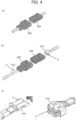
- FIG. 4(a) to FIG. 4(c) are perspective views of other examples of high-current connectors.
- the high-current connectors 500 and 600 shown in FIG. 4(a) are respectively made up of a socket contact 510 and a socket housing 520, and a pin contact 610 and a pin housing 620 as shown in FIG. 4(b).
- FIG. 4(c) is a perspective view of the socket contact 510 and the pin contact 610.
- the coating may be formed on a surface of the socket contact 510 and on a surface of the pin contact 610 by application of or immersion in the composition described above, as indicated by arrows C. Examples
- metals may be indicated by element symbols instead of names, for example Ag for silver and Cu for copper.
- compositions listed in the following tables contain the following components.
- Vertrel XF product name, manufactured by Chemours-Mitsui Fluoroproducts Co., Ltd.
- Vertrel XF product name, manufactured by Chemours-Mitsui Fluoroproducts Co., Ltd.
- Fluorinated oil having a polar group (specified oil)
- Silver particles Silbest reduction silver AGS-050 (product name), particle size 0.5 um, (manufactured by Tokuriki Honten, Co., Ltd.)
- compositions were prepared by mixing the above components in proportions listed in Tables 1 and 2 shown below.
- Each composition contains a specified oil and metal particles that interact with each other and form the specified metal particles described above, while part of the specified oil remains as is in the composition. Namely, the obtained Compositions 1, 2, and 11 to 20 contained specified oil and specified metal particles.
- Component Composition (Unit: mass%) 1 2 1H,1H-Perfluoro(2,5,8,11,14-pentamethyl-3,6,9,12,15-oxaoctadecan-1-ol) 1.000 0.000 1H,1H,2H,2H-Perfluorodecanethiol 0.000 1.000 Silver particles 1.000 1.000 Vertrel XF 98.000 98.000 Total 100.000 100.000 [Table 2] Component Composition (Unit: mass%) 10 11 12 13 14 15 16 17 18 19 20 1H,1H-Perfluoro(2,5,8,11,14-pentamethyl-3,6,9,12,15-oxaoctadecan-1-ol) 1.000 1.000 1.000 1.000 1.000 1.500 2.000 2.500 3.000 Silver particles 0.000 0.001 0.010 0.100 0.250 0.500 1.000 0.100 0.100 0.100 0.100 0.100 Vertrel XF 99.000 98.999 98.990 98.900
- the probes and the plates were coated by dipping with each type of compositions. After the coating, the probes and the plates were let dry naturally at normal temperature for one hour, and thus probes having a predetermined coating and plates having a predetermined coating were prepared.
- the probe having the predetermined coating was rubbed on the plate having the predetermined coating prepared as described above, and the friction coefficient and the contact resistance were measured using a measurement device and in measurement conditions described below.
- the contact resistance was measured both at the start of sliding and during sliding.
- the friction coefficient is a friction coefficient measured during sliding.
- a real-time observation was conducted simultaneously using a CCD camera, and the test was finished at a time point when exposure of a surface of Cu that is the base material was detected.
- Table 4 shown below shows the results of the test using Compositions 1 and 2.
- the contact resistance (at the start of sliding) in Table 4 shows a maximum value obtained before the number of sliding cycles exceeded two.
- the contact resistance (during sliding) and the friction coefficient (during sliding) show maximum values obtained after the number of sliding cycles exceeded two and until a Cu surface was exposed.
- the probe and the plate in Comparative Example 1 are not treated with the composition. Namely, the probe and the plate in Comparative Example 1 do not have the predetermined coating.
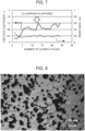
- FIG. 5, FIG. 6 , and FIG. 7 respectively show concrete test results of Comparative Example 1, Example 1, and Example 2.
- Comparative Example Example 1 1 2 Type of composition - 1 2 Probe-and-plate discoloration preventing treatment None None None Evaluation category Contact resistance (at the start of sliding) (m ⁇ ) 0.18 0.44 0.32 Contact resistance (during sliding) (m ⁇ ) 0.25 0.29 0.21 Friction coefficient (during sliding) 1.05 0.80 0.94 Number of sliding cycles before exposure of Cu surface (cycles) 10 25 13 Effect Poor Excellent Good Good
- Example 1 The number of sliding cycles until a Cu surface was exposed increased in Examples 1 and 2 as compared to Comparative Example 1, which means the sliding durability improved.
- Example 1 was more preferable, which revealed that 1H,1H-perfluoro(2,5,8,11,14-pentamethyl-3,6,9,12,15-oxaoctadecan-1-ol), which has a hydroxyl group as the polar group, was more preferable than the other, even though the main chain has a similar structure.
- Table 5 to be described later shows the results of the test using Composition 16.
- the probe and the plate in Comparative Example 2 are not treated with the composition. Namely, the probe and the plate in Comparative Example 2 do not have the predetermined coating.
- Comparative Example Example 2 3 4 Type of composition - 16 16 Probe-and-plate discoloration preventing treatment Done Done None Evaluation category Contact resistance (at the start of sliding) (m ⁇ ) 2.08 0.34 0.42 Contact resistance (during sliding) (m ⁇ ) 0.54 0.30 0.23 Friction coefficient (during sliding) 0.12 0.21 0.21 Number of sliding cycles before exposure of Cu surface (cycles) 100 15 25 Effect Poor Good Excellent
- Comparative Example 2 corresponds to an embodiment in which a coating of alkanethiol is formed on an Ag-plated surface as a treatment to prevent sulfidation. While Comparative Example 2 withstood 100 sliding cycles until a Cu surface was exposed, the contact resistance at the start of sliding was as high as 2.08 mQ, as compared to Comparative Example 1.
- Examples 3 and 4 indicated a good balance between low electrical resistance and sliding durability.
- Example 3 in which alkanethiol coating was formed and Example 4 in which no alkanethiol coating was formed were compared, Example 4 in which no alkanethiol coating was formed was found more preferable.
- Table 6 below shows the results of the test using Compositions 10 to 16.
- FIG. 8 , FIG. 9 , FIG. 10 , and FIG. 11 respectively show polarizing microscope images of the observed appearances of specified metal particles of Examples 10, 7, 6, and 5.
- the specified metal particles in the images are painted black by image recognition software for better visibility.
- Examples 5 to 10 indicated a good balance between low electrical resistance and sliding durability.
- Table 7 below shows the results of the test using Compositions 13 and 17 to 20.
- Comparative Example Example 1 11 12 13 14 15 Type of composition - 13 17 18 19 20 Probe-and-plate discoloration preventing treatment None None None None None Evaluation category
- Contact resistance (at the start of sliding) (m ⁇ ) 0.18 0.32 0.30 0.31 0.45 0.52
- Contact resistance (during sliding) (m ⁇ ) 0.25 0.33 0.24 0.15 0.31 0.42
- Friction coefficient (during sliding) 1.05 0.31 0.33 0.34 0.28 0.25 Number of sliding cycles before exposure of Cu surface (cycles) 10 45 300 More than 600 cycles 410 200 Effect Poor Good Excellent Excellent Excellent Good Good
- Examples 11 to 15 indicated a good balance between low electrical resistance and sliding durability.
- Examples 12 to 14 in particular, with compositions having a concentration of 1H,1H-perfluoro(2,5,8,11,14-pentamethyl-3,6,9,12,15-oxaoctadecan-1-ol) of 1.500 mass% to 2.500 mass%, showed outstanding sliding durability. In other words, superior effects were achieved when the ratio of the specified oil content (mass%) to the specified metal particle content (mass%) (specified oil content (mass%)/specified metal particle content (mass%)) was 15 to 25.
- Table 8 shows the results of the test using Composition 13. With Examples 16 to 20, a comparison was made on cases with different maximum heights Ry of plate surface roughness.
- Table 9 shows the results of the test using Compositions 10 to 16. With Examples 21 to 26, a comparison was made on cases with different ratios of the average secondary particle size of specified metal particles to the maximum height Ry of plate surface roughness.
- Comparative Example Example 4 21 22 23 24 25 26
- Type of composition 10 11 12 13 14 15 16
- Evaluation category Contact resistance (at the start of sliding) (m ⁇ ) 2.30 1.24 1.51 0.90 0.71 0.50 0.34
- Contact resistance (during sliding) (m ⁇ ) More than 5 m ⁇ 0.52 0.55 0.82
- Examples 21 to 26 indicated a good balance between low electrical resistance and sliding durability.
- Examples 23 to 25 in particular, with the ratio of the average secondary particle size of specified metal particles to the maximum height Ry of plate surface roughness (secondary particle size/maximum height Ry) being 1.0 to 1.2, proved preferable.
- FIG. 12 and FIG. 13 respectively show concrete test results of Example 27 and Example 31.
- Example 27 28 29 30 31 Type of composition 18 18 18 18 18 18 Vickers hardness of probe and plate (Hv) 180 150 120 90 60 Evaluation category Contact resistance (at the start of sliding) (m ⁇ ) 1.74 1.70 1.69 0.32 0.31 Contact resistance (during sliding) (m ⁇ ) 0.84 0.80 0.85 0.73 0.83 Friction coefficient (during sliding) 0.27 0.23 0.17 0.18 0.18 Number of sliding cycles before exposure of Cu surface (cycles) 43 620 More than 1200 cycles More than 1200 cycles More than 1200 cycles More than 1200 cycles Effect Good Good Excellent Excellent Excellent Excellent Examples 27 to 31 in which the plate and the probe had a Vickers hardness of not greater than 180 Hv indicated a good balance between low electrical resistance and sliding durability.
Landscapes
- Chemical & Material Sciences (AREA)
- Engineering & Computer Science (AREA)
- Chemical Kinetics & Catalysis (AREA)
- Organic Chemistry (AREA)
- Materials Engineering (AREA)
- Metallurgy (AREA)
- Mechanical Engineering (AREA)
- General Chemical & Material Sciences (AREA)
- Physics & Mathematics (AREA)
- Spectroscopy & Molecular Physics (AREA)
- Dispersion Chemistry (AREA)
- Oil, Petroleum & Natural Gas (AREA)
- Composite Materials (AREA)
- Nanotechnology (AREA)
- Lubricants (AREA)
- Electroplating Methods And Accessories (AREA)
- Manufacturing Of Electrical Connectors (AREA)
- Other Surface Treatments For Metallic Materials (AREA)
Abstract
Description
- The present invention relates to a contact member, a connector, a composition, and a method for producing the contact member.
- Efforts have been made to reduce resistance in electrical connection parts (connectors) that need to pass high current such as charging plugs for electrical vehicles, in order to minimize heat generation or power loss. This is why silver, gold, and copper, which have a low electrical resistivity, are used primarily as the material of contacts. Sometimes, gold- or silver-plated copper or copper alloys are used.
- Situations arise where two surfaces of electrical contacts repeatedly slide in contact with each other under a constant pressure, such as when two surfaces slide on each other due to repeated insertion and extraction, or when the contacts are subjected to vibration in the environment of use after being fitted together. Such sliding leads to adhesive wear at the contacts, and results in problems such as raised electrical resistance due to worn surfaces undergoing transformation such as oxidation, or an increase in an insertion and extraction force due to adhesion.
- Coating contact portions with organic component-containing compositions for providing lubrication effects is widely practiced to minimize such wear caused by sliding at contacts.
Patent Literature 1 discloses a technique for reducing friction resistance wherein a layer of silver plating is formed in electrical contact portions of a connecter terminal, on which a coating layer is further formed, the coating layer consisting of a film formed by contact with a solution containing thiol and benzotriazole.Patent Literature 2 discloses a technique for forming a coating of a mixture of fluororesin fine particles and fluorinated oil on electrical contact portions. -
- Patent Literature 1:
JP 2014-135191 A - Patent Literature 2:
JP 4348288 B2 - Meanwhile, contact members for high current applications, specifically, contact members that are low in resistance both at the start of sliding and during sliding, are in demand in recent years. Being low in resistance both at the start of sliding and during sliding as noted above is herein referred to also as showing low electrical resistance.
- The present inventors looked into the techniques described in
Patent Literatures - Namely, a contact member that strikes a balance between low electrical resistance and sliding durability is not found in prior art and is desired to be developed.
- The phrase "showing sliding durability", as used herein, is intended to mean having a low friction coefficient during sliding, as well as withstanding a large number of sliding cycles until a metal base in the contact member becomes exposed during sliding.
- In view of the above circumstances, an object of the present invention is to provide a contact member that strikes a balance between low electrical resistance and sliding durability.
- Intensive research conducted by the present inventors led to the finding that the above problem is able to be solved by the following configurations.
-
- (1) A contact member comprising: a metal base; and a coating disposed on at least part of the metal base, the coating containing fluorinated oil having a polar group, and metal particles surface-treated with a fluorine-based compound having a polar group.
- (2) The contact member according to (1), wherein a metal of the metal base is identical to that of the metal particles.
- (3) The contact member according to (1) or (2), wherein the polar group is a hydroxyl group.
- (4) The contact member according to any of (1) to (3), wherein a ratio of a content (mass%) of the fluorinated oil to a content (mass%) of the metal particles (fluorinated oil content (mass%)/metal particle content (mass%)) is 15 to 25.
- (5) The contact member according to any of (1) to (4), wherein the metal particles have an average secondary particle size of 1.7 µm to 2.1 um.
- (6) The contact member according to any of (1) to (5), wherein a ratio of an area of the metal particles to an area of the coating, when the coating is observed from a normal direction of the coating, is 3.6% to 15.0%.
- (7) The contact member according to any of (1) to (6), wherein the metal base has a Vickers Hardness of 180 Hv or less.
- (8) The contact member according to any of (1) to (7), wherein the metal base has surface roughness with a maximum height Ry of 0.5 um to 1.7 um.
- (9) The contact member according to (7) or (8), wherein a ratio of an average secondary particle size (um) of the metal particles to a maximum height Ry (µm) of surface roughness of the metal base (average secondary particle size (µm) of the metal particles/maximum height Ry (um) of surface roughness of the metal base) is 1.0 to 1.2.
- (10) A connector comprising the contact member according to any of (1) to (9).
- (11) A composition used for formation of a coating of a contact member including a metal base and the coating disposed on at least part of the metal base, the composition comprising: fluorinated oil having a polar group; and metal particles surface-treated with a fluorine-based compound having a polar group.
- (12) A method for producing the contact member according to any of (1) to (9), comprising the step of forming the coating by supplying the composition according to (11) on the metal base.
- The present invention can provide a contact member that strikes a balance between low electrical resistance and sliding durability.
-
-
FIG. 1 is a schematic diagram for describing a presumed mechanism of a contact member according to the present invention. -
FIG. 2 is a perspective view of a high-current connector. -
FIG. 3 is a perspective view of a high-current connector. -
FIG. 4 is a perspective view of a high-current connector. -
FIG. 5 is a chart showing the results of a sliding test of Comparative Example 1. -
FIG. 6 is a chart showing the results of a sliding test of Example 1. -
FIG. 7 is a chart showing the results of a sliding test of Example 2. -
FIG. 8 is a polarizing microscope image of Example 10. -
FIG. 9 is a polarizing microscope image of Example 7. -
FIG. 10 is a polarizing microscope image of Example 6. -
FIG. 11 is a polarizing microscope image of Example 5. -
FIG. 12 is a chart showing the results of a sliding test of Example 27. -
FIG. 13 is a chart showing the results of a sliding test of Example 31. - Embodiments of this invention are described below based on the appended drawings.
- Any numerical range expressed using "to", as used herein, is intended to include the values recited before and after "to" as the lower limit and upper limit.
- A contact member according to the present invention includes a metal base and a coating disposed on at least part of the metal base. The coating contains fluorinated oil having a polar group, and metal particles surface-treated with a fluorine-based compound having a polar group.
- Various parts included in the contact member of the present invention are described in detail below.
- The metal base constitutes an electrical contact in the contact member of the present invention.
- Materials constituting the metal base are not limited in particular and desired to be low in electrical resistance. Preferable constituent materials for the metal base are silver, gold, or copper.
- The metal base may have a single-layer structure, or a multilayer structure.
- In the case where the metal base has a multilayer structure, the metal base may have a base material (metal support) and a plating layer disposed on a surface of the base material. While examples of metals for the plating layer particularly low in electrical resistance are gold, silver, and copper, materials constituting the plating layer are not limited in particular and may be other metals such as, for example, tin, nickel, platinum, rhodium, and various alloys made by adding other metals to these metals to adjust hardness or corrosion resistance, i.e., any metal having electrical conductivity and useable as plating metal.
- The surface of the metal base may be treated in various ways. For example, the metal base may be surface-treated to prevent discoloration. One example of surface treatment for preventing discoloration is a treatment of forming a film of alkanethiol on the surface of the metal base (if the metal base has a plating layer, on the surface of the plating layer).
- The metal base preferably has a Vickers hardness of 180 Hv or less, and more preferably 120 Hv or less.
- The lower limit of the Vickers hardness of the metal base is preferably, but not particularly limited to, 3 Hv or more.
- The metal base has surface roughness, in most cases with a maximum height Ry (maximum height Ry of surface roughness of the surface on a coated side of the metal base) of 0.1 µm to 5.0 µm, but not particularly limited thereto. The maximum height Ry is preferably 0.5 µm to 1.7 µm for better sliding durability of the contact member.
- The maximum height Ry of the surface roughness of the metal base can be controlled by a known method. For a metal base that does not have a plating layer, for example, the maximum height of surface roughness can be controlled by machining conditions of a cutting operation such as cutting depth and feed pitch, or by surface treatment such as blasting or chemical etching after the cutting operation. For a metal base that has a plating layer, the maximum height of surface roughness can also be controlled by plating conditions such as deposition speed and temperature.
- The coating is a layer disposed on at least part of the metal base described above.
- The coating may be disposed on an entire surface of the metal base, or on some part of the metal base. In cases where the coating is disposed on some part of the metal base, the coating may be located on one or both of opposing two main surfaces of the metal base.
- The coating contains fluorinated oil having a polar group (hereinafter also referred to simply as "specified oil").
- Fluorinated oil is a compound that contains a fluorine atom in the molecule and takes on an oil form. Oil form here is intended to mean a liquid form at room temperature (23°C).
- Fluorinated oil often has a shear viscosity of 0.7 to 2.5 Pa·s in a shear rate range of 0.01 to 1000 s-1, and preferably has a shear viscosity of 0.1 to 5.0 Pa·s in a shear rate range of 0.01 to 1000 s-1.
- The molecular weight of the specified oil is not limited in particular. For striking a balance between low electrical resistance and sliding durability, the specified oil preferably has a molecular weight of 300 to 2000, and more preferably 300 to 1000.
- Here, the term "molecular weight" is intended to mean chemical formula weight. Note that, however, mass-average molecular weight is used as the molecular weight for polymer or oligomer compounds whose chemical formula weight cannot be specified uniquely for reasons such as the chemical formula weight being different depending on individual molecules. The method for measuring the mass-average molecular weight is not limited in particular. Preferably, the mass-average molecular weight may be measured using gel permeation chromatography (GPC). The standard polymer and solvent (mobile phase) used for the measurement of mass-average molecular weight by GPC may be selected as suited to a target fluorinated oil whose mass-average molecular weight is to be measured.
- Examples of a polar group in the specified oil include, but not particularly limited to, a hydroxyl group, a thiol group, an amino group, an epoxy group, a methacryloxy group, an acryloxy group, and a carboxy group. For striking a balance between electrical resistance and sliding durability, a hydroxyl group or a thiol group is preferable, with a hydroxyl group being more preferable.
- The specified oil may have any number of polar groups, which is for example one, but not particularly limited thereto, and may be two or more. In particular, the number of polar groups is preferably 1 to 4, and more preferably 1, for striking a balance between low electrical resistance and sliding durability.
- The position of the polar group in the specified oil is not limited in particular. For striking a balance between low electrical resistance and sliding durability, the specified oil has a polar group preferably at the end of a chain.
- The specified oil may have a straight chain, or a branched chain. The fluorinated oil may also include a cyclic structure.
- The specified oil includes a skeleton containing a fluorine atom such as a fluorocarbon skeleton, a perfluoropolyether skeleton, a fluorine-modified silicone skeleton, and a fluoroester skeleton, in addition to a polar group.
- A perfluoroether skeleton is a skeleton configured with a repeating unit represented by Formula (A).
Formula (A) -(OL1)-
- L1 represents a perfluoroalkylene group. The perfluoroalkylene group preferably contains 1 to 10, more preferably 2 to 6, and even more preferably 2 to 3 carbon atoms.
- Examples of preferable specified oils include a compound represented by Formula (1), and a compound represented by Formula (2).
Formula (1) (Rf-(OL1))n-L2-(R1)m
Formula (2) (R2-L2-(R1))m
- L1 in Formula (1) is as defined above.
- The letter n represents an integer of 2 or more. In particular, n is preferably 3 to 20, and more preferably 3 to 6, for striking a balance between low electrical resistance and sliding durability.
- L2 in Formula (1) represents an (m + 1)-valent aliphatic hydrocarbon group. For example, when m = 1, L2 represents a divalent aliphatic hydrocarbon group, and when m = 2, L2 represents a trivalent aliphatic hydrocarbon group. The number of carbon atoms in the aliphatic hydrocarbon group is not limited in particular. Preferably, the aliphatic hydrocarbon group contains 1 to 10, more preferably 1 to 6, and even more preferably 1 to 3 carbon atoms.
- Rf in Formula (1) represents a perfluoroalkyl group. The perfluoroalkyl group preferably contains 1 to 5, and more preferably 2 to 4 carbon atoms.
- R1 in Formula (1) represents a polar group. Preferable examples of polar groups are as listed above. The letter m in Formula (1) represents an integer of 1 or more. In particular, m is preferably 1 to 4, and more preferably 1 to 2, for striking a balance between low electrical resistance and sliding durability.
- R2 in Formula (2) represents a perfluoroalkyl group. The number of carbon atoms in the perfluoroalkyl group is not limited in particular. Preferably, the perfluoroalkyl group contains 4 to 20, more preferably 5 to 15, and even more preferably 6 to 12 carbon atoms.
- The definitions of L2, R1, and m in Formula (2) are the same as the definitions of respective groups in Formula (1) .
- Examples of specified oils include, for example, 1H,1H-heptadecafluoro-1-nonanol, 1H,1H,10H,10H-hexadecafluoro-1,10-decanediol, 1H,1H-perfluoro-3,6,9-trioxadecan-1-ol, 1H,lH,11H,11H-dodecafluoro-3,6,9-trioxaundecane-1,11-diol, 1H,1H,2H,2H-perfluorodecan-1-ol, 3,5-bis(trifluoromethyl)benzen-1-ol, 1H,1H-perfluoro(2,5,8,11,14-pentamethyl-3,6,9,12,15-oxaoctadecan-1-ol), 1H,1H,2H,2H-perfluorodecanethiol, and 3,5-bis(trifluoromethyl)benzenethiol.
- Commercially available products may also be used as the specified oil. Commercially available products include, for example, MORESCO PHOSFAROL A-20H (manufactured by MORESCO Corporation), DEMNUM (registered trademark) S-65 (manufactured by DAIKIN Industries, Ltd.), and FOMBLIN (registered trademark) ZDOL (manufactured by Solvay).
- The specified oil content in the coating is preferably, but not particularly limited to, 50.00 mass% to 99.99 mass%, and more preferably 60.00 to 97.00 mass% relative to the total mass of the coating, for striking a balance between low electrical resistance and sliding durability.
- One type of specified oil may be used alone, or two or more types may be used in combination.
- The coating contains metal particles surface-treated with a fluorine-based compound having a polar group (hereinafter also referred to simply as "specified metal particles").
- The specified metal particles in the coating serve as an electrical contact.
- The metals in the specified metal particles are not limited to a particular metal and may be any of known metals such as, typically, silver, gold, copper, tin, and nickel. In particular, for striking a balance between low electrical resistance and sliding durability, the metal of the metal base described above is preferably the same as the metal of the specified metal particles.
- In the case where the metal base has a plating layer, the metal forming the plating layer is preferably the same as the metal of the specified metal particles.
- The specified metal particles contain a fluorine-based compound having a polar group (hereinafter also referred to simply as "specified compound"). The specified compound functions as a surface modifier of the metal particles.
- The specified compound contains a polar group that may be, but not limited particularly to, one of the examples of polar groups of the specified oil listed above.
- The specified compound is not limited to a particular compound as long as it contains a polar group and a fluorine atom. In particular, the specified oils listed above are preferable for striking a balance between low electrical resistance and sliding durability.
- The specified metal particles have an average primary particle size that is not limited in particular but preferably 0.2 um to 10.0 um, and more preferably 0.5 µm to 2.0 um, for striking a balance between low electrical resistance and sliding durability.
- The average primary particle size of the specified metal particles is an arithmetic average value obtained by measuring the diameters (particle sizes) of 20 or more specified metal particles using an electron microscope. For any of the observed specified metal particles that are not an exact circle, the size of a longer side is measured as the diameter.
- The specified metal particles in the coating have an average secondary particle size that is mostly, but not particularly limited to, 0.2 um to 10.0 um, and preferably 1.7 µm to 2.1 um for striking a balance between low electrical resistance and sliding durability.
- The average secondary particle size of the specified metal particles in the coating is an arithmetic average value obtained by measuring the diameters (secondary particle sizes) of 20 aggregates of specified metal particles observed when the coating is observed using a polarizing microscope from a normal direction of the coating. For any of the observed aggregates of specified metal particles that are not an exact circle, the size of a longer side is measured as the diameter.
- While the above method obtains an average secondary particle size from 20 aggregates of specified metal particles, the specified metal particles in the same coating are not expected to produce a significant difference in the average secondary particle size.
- The specified metal particle content in the coating is preferably, but not particularly limited to, 0.01 to 50.00 mass%, and more preferably 3.00 to 40.00 mass% relative to the total mass of the coating, for striking a balance between low electrical resistance and sliding durability.
- One type of specified metal particles may be used alone, or two or more types may be used in combination.
- The ratio of the specified oil content (mass%) to the specified metal particle content (mass%) (specified oil content (mass%)/specified metal particle content (mass%)) is, in most cases, but not particularly limited to, 1 to 1000, preferably 10 to 30, and more preferably 15 to 25, for striking a balance between low electrical resistance and sliding durability.
- The ratio of the average secondary particle size (um) of the specified metal particles to the maximum height Ry (um) of the surface roughness of the metal base mentioned above (average secondary particle size (µm) of specified metal particles/maximum height Ry (µm) of surface roughness of metal base) is, in most cases, but not particularly limited to, 0.1 to 2.0, and preferably 1.0 to 1.2 for striking a balance between low electrical resistance and sliding durability.
- The ratio of the area of the specified metal particles to the area of the coating as observed from a normal direction of the coating is in most cases, but not particularly limited to, 0.1% to 50.0%, preferably 0.6% to 30.2%, and more preferably 3.6% to 15.0%, for striking a balance between low electrical resistance and sliding durability.
- The ratio of the area of the specified metal particles to the area of the coating is intended to mean a ratio of an area taken up by specified metal particles to an area of coating in an observed region when the coating is observed using a polarizing microscope from a normal direction of the coating. The polarizing microscope has an observation area of 0.11 cm × 0.07 cm, and the ratio of the area of the specified metal particles to the area of the coating is an average value of the ratios obtained by the observation at five or more random points of the coating. Some parts of the area taken up by the specified metal particles may include aggregates of the specified metal particles.
- While the above method obtains a ratio of an area of specified metal particles to an area of coating by observation at five or more random points of the coating, the same coating is not expected to produce a significant difference in the ratio of the area of specified metal particles to the area of coating.
- The method for producing the specified metal particles is not limited to a particular one and may be any of known methods.
- For example, specified metal particles may be produced by mixing a specified compound and metal particles in the presence of a solvent.
- In the case where a specified compound and metal particles are mixed such that the specified compound remains in excess in the solution produced as above, the solution thus obtained can be used as a composition for use in producing the contact member to be described later.
- The method for producing the contact member is not limited to a particular one and may be any of known methods.
- Supplying a composition that contains a specified oil and specified metal particles onto a metal base is one example of a highly productive method of forming a coating.
- The composition is designed for forming the coating and contains the specified oil and specified metal particles described above.
- The specified oil content in the composition is preferably, but not particularly limited to, 1.000 to 3.000 mass%, and more preferably 1.500 to 2.500 mass% relative to the total mass of the composition, for striking a balance between low electrical resistance and sliding durability.
- The content of specified metal particles in the composition is preferably, but not particularly limited to, 0.001 to 1.000 mass%, and more preferably 0.100 to 0.500 mass% relative to the total mass of the composition, for striking a balance between low electrical resistance and sliding durability.
- The ratio of the specified oil content (mass%) to the specified metal particle content (mass%) in the composition (specified oil content (mass%)/specified metal particle content (mass%)) is not limited in particular and is preferably in the range of the ratio in the coating specified above.
- The composition may contain a solvent.
- Examples of the solvent include, but not particularly limited to, an alcohol-based solvent, an ester-based solvent, a ketone-based solvent, an aliphatic hydrocarbon-based solvent, an alicyclic or aromatic hydrocarbon-based solvent, a halogenated hydrocarbon-based solvent, and a fluorine-based solvent.
- The solvent content in the composition is preferably, but not particularly limited to, 50.000 to 99.990 mass%, and more preferably 80.000 to 99.000 mass% relative to the total mass of the composition, for striking a balance between low electrical resistance and sliding durability.
- One type of solvent may be used alone, or two or more types may be used in combination.
- The composition may be supplied onto the metal base by any method such as, but not particularly limited to, applying the composition on the metal base, or immersing the metal base in the composition.
- After supplying the composition on the metal base, a drying process may be carried out as required for evaporation of the solvent. Alternatively, the metal base may be naturally dried to let the solvent evaporate.
- While the mechanism in the contact member of the present invention whereby the desired effect is achieved is not clear, a presumed mechanism is described using
FIG. 1 . - FIG. 1(a) and FIG. 1(b) are schematic diagrams for describing a presumed mechanism of the contact member of the present invention. FIG. 1(a) and FIG. 1(b) show a case where a
metal base 11 has a predetermined roughness. In the illustrated case, a specified oil, i.e., fluorinated oil having a polar group, is used for the surface treatment ofmetal particles 14. - A
coating 12 is formed on a surface of themetal base 11 of acontact member 10 of the present invention. More specifically, the molecules of thefluorinated oil 15 having a polar group bond together and form a monomolecular layer on the surface of themetal base 11. On the top of this monomolecular layer, there is formed a fluidized layer of thefluorinated oil 15 that is loosely retained by entanglement of molecular chains. Themetal particles 14, with thefluorinated oil 15 bonded to their surfaces by a surface treatment, are dispersed in this fluidized layer. Namely, thecoating 12 includes the monomolecular layer and the fluidized layer. - Adhesion occurs when the
metal particles 14 dispersed in the fluidized layer of thefluorinated oil 15 are pressed against a surface of themetal base 11 by a terminal 100 and deformed, which establishes electrical connection. Low electrical resistance is thus achieved. - The unit of the adhesion is as low as or lower than that of the
metal particle 14 because of the presence of thefluorinated oil 15 around eachmetal particle 14. Since the adhesion points are very small and distributed, the adhered metals readily separate by application of a small stress. Therefore, while adhesion occurs, it does not develop to cause wear. Sliding durability is thus achieved. - When the
metal particles 14 come to a condition where they are embedded in themetal base 11 as shown in FIG. 1(b), this allows thefluorinated oil 15 to be retained inside themetal base 11, letting the oil appear on the surface of themetal base 11 again and function as the fluidized layer when the terminal 100 slides. In this way, themetal particles 14 carrying thefluorinated oil 15 bonded to their surfaces function as a new supply mechanism that prevents shortage of lubricant in a place where sliding is carried out and that allows repeated use of the lubricant. - In order to retain the
metal particles 14 and thefluorinated oil 15 in themetal base 11, and more specifically, in order for themetal particles 14 carrying thefluorinated oil 15 bonded to their surfaces to function as a new supply mechanism of repeatedly useable lubricant, it is important to create a condition that allows themetal particles 14 to be embedded in themetal base 11. In order to create a condition where themetal particles 14 are embedded in themetal base 11, it is preferable that themetal base 11 undergo deformation in response to stress. To achieve this, the hardness of themetal base 11 may be controlled as an index of deformation of themetal base 11 relative to stress. Specifically, the Vickers hardness of themetal base 11 is preferably controlled to not exceed 180 Hv. - Solid solution strengthening, precipitation strengthening, work hardening, and crystal grain refinement are commonly used metal hardening means. Various metal materials have found practical application as contact materials, such as, for example, Cu-Ni-Si alloys (known as Corson alloys), a type of precipitation-strengthened copper alloy, and "hardened silver plating" hardened by solid solution strengthening wherein a small amount of metal (such as selenium, antimony, or bismuth) is added during silver plating. In some cases, pure silver is plated and work-hardened afterwards by barrel polishing, since addition of a different kind of metal increases electrical resistance and is not preferable.
- In any case, these conventional techniques are employed to make materials for contacts harder to improve sliding durability.
- Meanwhile, according to the present invention, the Vickers hardness of the
metal base 11 is preferably controlled to not exceed 180 Hv in order to create a condition wheremetal particles 14 are embedded in themetal base 11. - The contact member of the present invention is applicable to various uses.
- The contact member of the present invention may for example be applied to an electronic component or an electrical device used for turning on and off the current to a switch or a relay. Namely, the present invention also relates to a connector having the contact member.
- In usage, the contact members of the present invention may be used such as to slide on each other with their coatings facing each other.
- The contact member of the present invention is favorably applied to high-current connectors.
-
FIG. 2 is a perspective view of one example of a high-current connector. The particulars of the high-current connector 200 ofFIG. 2 are described inJP 2013-8511 A current connector 200 ofFIG. 2 , the coating may be formed on a surface of aplug part 220 of aplug connector 210, a surface of asocket part 240 of areceptacle connector 230, and an entire surface of acontact unit 250, which form a sliding part of a terminal, by application of or immersion in the composition described above, as indicated by arrows C. -
FIG. 3(a) and FIG. 3(b) are perspective views of another example of a high-current connector. The particulars of the high-current connector 300 ofFIG. 3 are described inJP 2013-218837 A FIG. 3(a) is a perspective view of theconnector 300 before aconnection target 400 is inserted into theconnector 300, andFIG. 3(b) is a perspective view of theconnector 300 with theconnection target 400 inserted into theconnector 300.FIG. 3(c) is a cross-sectional view of theconnector 300 with theconnection target 400 inserted into theconnector 300. Arrow DI indicates the inserting direction of theconnection target 400. Theconnector 300 includes aconductive holder 320 and acontact 340. When applying the contact member of the present invention to the high-current connector 300 ofFIG. 3 , the coating may be formed on a surface of thecontact 340 and on an entire surface of theconnection target 400 by application of or immersion in the composition described above, as indicated by arrows C. -
FIG. 4(a) to FIG. 4(c) are perspective views of other examples of high-current connectors. The high-current connectors FIG. 4(a) are respectively made up of asocket contact 510 and asocket housing 520, and apin contact 610 and apin housing 620 as shown inFIG. 4(b). FIG. 4(c) is a perspective view of thesocket contact 510 and thepin contact 610. When applying the contact member of the present invention to the high-current connectors FIG. 4 , the coating may be formed on a surface of thesocket contact 510 and on a surface of thepin contact 610 by application of or immersion in the composition described above, as indicated by arrows C. Examples - The present invention is described in more specific terms below using Examples, without any intention of limiting the present invention to the examples.
- In the description of Examples, metals may be indicated by element symbols instead of names, for example Ag for silver and Cu for copper.
- The compositions listed in the following tables contain the following components.
- Vertrel XF (product name, manufactured by Chemours-Mitsui Fluoroproducts Co., Ltd.) containing a compound of the following formula.

- 1H,1H-Perfluoro(2,5,8,11,14-pentamethyl-3,6,9,12,15-oxaoctadecan-1-ol) (following formula)

- 1H,1H,2H,2H-Perfluorodecanethiol (following formula)

- Silver particles: Silbest reduction silver AGS-050 (product name), particle size 0.5 um, (manufactured by Tokuriki Honten, Co., Ltd.)
- Compositions were prepared by mixing the above components in proportions listed in Tables 1 and 2 shown below. Each composition contains a specified oil and metal particles that interact with each other and form the specified metal particles described above, while part of the specified oil remains as is in the composition. Namely, the obtained
Compositions [Table 1] Component Composition (Unit: mass%) 1 2 1H,1H-Perfluoro(2,5,8,11,14-pentamethyl-3,6,9,12,15-oxaoctadecan-1-ol) 1.000 0.000 1H,1H,2H,2H-Perfluorodecanethiol 0.000 1.000 Silver particles 1.000 1.000 Vertrel XF 98.000 98.000 Total 100.000 100.000 [Table 2] Component Composition (Unit: mass%) 10 11 12 13 14 15 16 17 18 19 20 1H,1H-Perfluoro(2,5,8,11,14-pentamethyl-3,6,9,12,15-oxaoctadecan-1-ol) 1.000 1.000 1.000 1.000 1.000 1.000 1.000 1.500 2.000 2.500 3.000 Silver particles 0.000 0.001 0.010 0.100 0.250 0.500 1.000 0.100 0.100 0.100 0.100 Vertrel XF 99.000 98.999 98.990 98.900 98.750 98.500 98.000 98.400 97.900 97.400 96.100 Total 100.000 100.000 100.000 100.000 100.000 100.000 100.000 100.000 100.000 100.000 100.000 - For production of samples to be used in an evaluation test (sliding test), the following probe and plate were prepared.
- Probe: Pin probe
- Contact shape: Spherical with 1 mm radius of curvature
- Base material: C1100 (tough pitch copper)
- Plating type: Soft Ag plating
- Plating thickness: 5 µm
- Plate: Test piece
- Base material: C1100 (tough pitch copper)
- Plating type: Soft Ag plating
- Plating thickness: 5 um
- Two types of samples, one with discoloration preventing treatment after Ag plating (alkanethiol film formation), and the other without the discoloration preventing treatment (non-treated Ag-plated surface) were prepared for both of the probe and the plate.
- Next, using the compositions produced as described above, the probes and the plates were coated by dipping with each type of compositions. After the coating, the probes and the plates were let dry naturally at normal temperature for one hour, and thus probes having a predetermined coating and plates having a predetermined coating were prepared.
- These probes and plates prepared as described above correspond to the contact member.
- The probe having the predetermined coating was rubbed on the plate having the predetermined coating prepared as described above, and the friction coefficient and the contact resistance were measured using a measurement device and in measurement conditions described below. The contact resistance was measured both at the start of sliding and during sliding. The friction coefficient is a friction coefficient measured during sliding.
- A real-time observation was conducted simultaneously using a CCD camera, and the test was finished at a time point when exposure of a surface of Cu that is the base material was detected.
-
- Friction and wear tester with simultaneous measurement of electrical contact resistance FPR-2300 (RHESCA Co., Ltd.) 0024
- Measurement Conditions
- Sliding distance: 10 mm
- Sliding speed: 10 mm/s
- Contact load: 6 N
- Number of cycles: Test ended when exposure of Cu surface was detected
- The test conducted as above was followed by evaluation of the following four categories (1) to (4).
- (1) Contact resistance (at the start of sliding)
- (2) Contact resistance (during sliding)
- (3) Friction coefficient (during sliding)
- (4) Number of sliding cycles until a Cu surface becomes exposed
- For each of the above (1) to (4) categories, it is judged that a desired effect is achieved when reference values in Table 3 shown below are satisfied. For the contact resistance (at the start of sliding), for example, if it is less than 2.00 mΩ, it is judged that the desired effect is achieved.
[Table 3] Evaluation category Reference value (1) Contact resistance (at the start of sliding) (mΩ) Less than 2.00 (2) Contact resistance (during sliding) (mΩ) Less than 2.00 (3) Friction coefficient (during sliding) Less than 1.00 (4) Number of sliding cycles before exposure of Cu surface (cycles) More than 10 - In the rows "Effect" in Tables 4 to 9 shown below, "good" represents a case that satisfies the reference values in all of the above evaluation categories, and "excellent" represents a case with particularly good characteristics among these.
- "Poor" represents a case that fails to satisfy a reference value even in one of the above evaluation categories.
- Table 4 shown below shows the results of the
test using Compositions - The probe and the plate in Comparative Example 1 are not treated with the composition. Namely, the probe and the plate in Comparative Example 1 do not have the predetermined coating.
-
FIG. 5, FIG. 6 , andFIG. 7 respectively show concrete test results of Comparative Example 1, Example 1, and Example 2.[Table 4] Comparative Example Example 1 1 2 Type of composition - 1 2 Probe-and-plate discoloration preventing treatment None None None Evaluation category Contact resistance (at the start of sliding) (mΩ) 0.18 0.44 0.32 Contact resistance (during sliding) (mΩ) 0.25 0.29 0.21 Friction coefficient (during sliding) 1.05 0.80 0.94 Number of sliding cycles before exposure of Cu surface (cycles) 10 25 13 Effect Poor Excellent Good - The number of sliding cycles until a Cu surface was exposed increased in Examples 1 and 2 as compared to Comparative Example 1, which means the sliding durability improved. Example 1 was more preferable, which revealed that 1H,1H-perfluoro(2,5,8,11,14-pentamethyl-3,6,9,12,15-oxaoctadecan-1-ol), which has a hydroxyl group as the polar group, was more preferable than the other, even though the main chain has a similar structure.
- Table 5 to be described later shows the results of the test using Composition 16. The probe and the plate in Comparative Example 2 are not treated with the composition. Namely, the probe and the plate in Comparative Example 2 do not have the predetermined coating.
[Table 5] Comparative Example Example 2 3 4 Type of composition - 16 16 Probe-and-plate discoloration preventing treatment Done Done None Evaluation category Contact resistance (at the start of sliding) (mΩ) 2.08 0.34 0.42 Contact resistance (during sliding) (mΩ) 0.54 0.30 0.23 Friction coefficient (during sliding) 0.12 0.21 0.21 Number of sliding cycles before exposure of Cu surface (cycles) 100 15 25 Effect Poor Good Excellent - Comparative Example 2 corresponds to an embodiment in which a coating of alkanethiol is formed on an Ag-plated surface as a treatment to prevent sulfidation. While Comparative Example 2 withstood 100 sliding cycles until a Cu surface was exposed, the contact resistance at the start of sliding was as high as 2.08 mQ, as compared to Comparative Example 1.
- In comparison to this, Examples 3 and 4 indicated a good balance between low electrical resistance and sliding durability. When Example 3 in which alkanethiol coating was formed and Example 4 in which no alkanethiol coating was formed were compared, Example 4 in which no alkanethiol coating was formed was found more preferable.
- Table 6 below shows the results of the
test using Compositions 10 to 16.FIG. 8 ,FIG. 9 ,FIG. 10 , andFIG. 11 respectively show polarizing microscope images of the observed appearances of specified metal particles of Examples 10, 7, 6, and 5. The specified metal particles in the images are painted black by image recognition software for better visibility. - The values in the row "Area percentage of specified metal particles (%)" in Table 6 correspond to the ratio (%) of an area of specified metal particles to an area of coating when the coating is observed from a normal direction of the coating as described above, which is measured as described in the foregoing.
[Table 6] Comparative Example Example 3 5 6 7 8 9 10 Type of composition 10 11 12 13 14 15 16 Probe-and-plate discoloration preventing treatment Done Done Done Done Done Done Done Area percentage of specified metal particles (%) 0.0 0.6 1.5 3.6 7.5 15.0 30.2 Average secondary particle size of specified metal particles (µm) 0.0 0.2 0.6 1.7 1.9 2.1 2.3 Evaluation category Contact resistance (at the start of sliding) (mΩ) 2.30 1.24 1.51 0.90 0.71 0.50 0.34 Contact resistance (during sliding) (mΩ) More than 5 mΩ 0.52 0.51 0.82 0.62 0.34 0.30 Friction coefficient (during sliding) 0.12 0.13 0.13 0.24 0.24 0.22 0.21 Number of sliding cycles before exposure of Cu surface (cycles) More than 600 cycles 45 48 206 104 44 15 Effect Poor Good Good Excellent Excellent Excellent Good - While Comparative Example 3 with a composition not containing silver particles withstood more than 600 sliding cycles until a Cu surface was exposed, the contact resistance at the start of sliding was high. While the friction coefficient was consistent, the contact resistance soared suddenly to more than 5 mQ, hence the result is "poor."
- Examples 5 to 10 indicated a good balance between low electrical resistance and sliding durability.
- A comparison of Examples 5 to 10 revealed that better results were achieved when the specified metal particles had an average secondary particle size of 1.7 µm to 2.1 um. Also, the results were better when the area percentage (%) of specified metal particles was 3.6% to 15.0%.
- Table 7 below shows the results of the test using Compositions 13 and 17 to 20.
[Table 7] Comparative Example Example 1 11 12 13 14 15 Type of composition - 13 17 18 19 20 Probe-and-plate discoloration preventing treatment None None None None None None Evaluation category Contact resistance (at the start of sliding) (mΩ) 0.18 0.32 0.30 0.31 0.45 0.52 Contact resistance (during sliding) (mΩ) 0.25 0.33 0.24 0.15 0.31 0.42 Friction coefficient (during sliding) 1.05 0.31 0.33 0.34 0.28 0.25 Number of sliding cycles before exposure of Cu surface (cycles) 10 45 300 More than 600 cycles 410 200 Effect Poor Good Excellent Excellent Excellent Good - Examples 11 to 15 indicated a good balance between low electrical resistance and sliding durability.
- Examples 12 to 14, in particular, with compositions having a concentration of 1H,1H-perfluoro(2,5,8,11,14-pentamethyl-3,6,9,12,15-oxaoctadecan-1-ol) of 1.500 mass% to 2.500 mass%, showed outstanding sliding durability. In other words, superior effects were achieved when the ratio of the specified oil content (mass%) to the specified metal particle content (mass%) (specified oil content (mass%)/specified metal particle content (mass%)) was 15 to 25.
- Table 8 below shows the results of the test using Composition 13. With Examples 16 to 20, a comparison was made on cases with different maximum heights Ry of plate surface roughness.
[Table 8] Example 16 17 18 19 20 Type of composition 13 13 13 13 13 Maximum height Ry of plate surface roughness (µm) 0.3 0.5 0.9 1.7 3.9 Evaluation category Contact resistance (at the start of sliding) (mΩ) 1.22 1.10 1.32 0.90 0.33 Contact resistance (during sliding) (mΩ) 0.53 0.53 0.51 0.82 0.32 Friction coefficient (during sliding) 0.14 0.21 0.12 0.24 0.26 Number of sliding cycles before exposure of Cu surface (cycles) 15 45 48 206 14 Effect Good Excellent Excellent Excellent Good - Examples 16 to 20 with the maximum height Ry of plate surface roughness being 0.3 um to 3.9 µm withstood large numbers of sliding cycles until a Cu surface was exposed. Examples 17 to 19, in particular, having a maximum height Ry of plate surface roughness of 0.5 um to 1.7 um, proved preferable.
- Table 9 below shows the results of the
test using Compositions 10 to 16. With Examples 21 to 26, a comparison was made on cases with different ratios of the average secondary particle size of specified metal particles to the maximum height Ry of plate surface roughness.[Table 9] Comparative Example Example 4 21 22 23 24 25 26 Type of composition 10 11 12 13 14 15 16 Probe-and-plate discoloration preventing treatment Done Done Done Done Done Done Done Average secondary particle size of specified metal particles (µm) 0.0 0.2 0.6 1.7 1.9 2.1 2.3 Maximum height Ry of plate surface roughness (µm) 1.7 1.7 1.7 1.7 1.7 1.7 1.7 Secondary particle size (um) / Surface roughness Ry (µm) 0.0 0.1 0.3 1.0 1.1 1.2 1.3 Evaluation category Contact resistance (at the start of sliding) (mΩ) 2.30 1.24 1.51 0.90 0.71 0.50 0.34 Contact resistance (during sliding) (mΩ) More than 5 mΩ 0.52 0.55 0.82 0.62 0.34 0.30 Friction coefficient (during sliding) 0.12 0.13 0.13 0.24 0.24 0.22 0.21 Number of sliding cycles before exposure of Cu surface (cycles) More than 600 cycles 45 48 206 104 44 15 Effect Poor Good Good Excellent Excellent Excellent Good - While Comparative Example 4 with a composition not containing silver particles withstood 600 or more sliding cycles until a Cu surface was exposed, the contact resistance at the start of sliding was high. While the friction coefficient was consistent, the contact resistance soared suddenly to more than 5 mQ, hence the result is "poor."
- Examples 21 to 26 indicated a good balance between low electrical resistance and sliding durability.
- Examples 23 to 25, in particular, with the ratio of the average secondary particle size of specified metal particles to the maximum height Ry of plate surface roughness (secondary particle size/maximum height Ry) being 1.0 to 1.2, proved preferable.
- Five types of Ag-plated probes and plates were prepared with differing Vickers hardnesses Hv (180, 150, 120, 90, and 60) as samples to be used in the evaluation test (sliding test). Each combination of probe and plate had the same Vickers hardness. The probes and the plates were treated with Composition 18. Table 10 below shows the results.
-
FIG. 12 andFIG. 13 respectively show concrete test results of Example 27 and Example 31.[Table 10] Example 27 28 29 30 31 Type of composition 18 18 18 18 18 Vickers hardness of probe and plate (Hv) 180 150 120 90 60 Evaluation category Contact resistance (at the start of sliding) (mΩ) 1.74 1.70 1.69 0.32 0.31 Contact resistance (during sliding) (mΩ) 0.84 0.80 0.85 0.73 0.83 Friction coefficient (during sliding) 0.27 0.23 0.17 0.18 0.18 Number of sliding cycles before exposure of Cu surface (cycles) 43 620 More than 1200 cycles More than 1200 cycles More than 1200 cycles Effect Good Good Excellent Excellent Excellent - It was revealed that Examples 29 to 31, in particular, in which the plate and the probe had a Vickers hardness of not greater than 120 Hv, were preferable.
-
- 100: terminal
- 10: contact member
- 11: metal base
- 12: coating
- 14: metal particles
- 15: fluorine-based compound having a polar group
- 200: high-current connector
- 210: plug connector
- 220: plug part
- 230: receptacle connector
- 240: socket part
- 250: contact unit
- 300: high-current connector
- 320: conductive holder
- 340: contact
- 400: connection target
- 500, 600: high-current connector
- 510: socket contact
- 520: socket housing
- 610: pin contact
- 620: pin housing
Claims (12)
- A contact member comprising: a metal base; and a coating disposed on at least part of the metal base, the coating containing fluorinated oil having a polar group, and metal particles surface-treated with a fluorine-based compound having a polar group.
- The contact member according to claim 1, wherein a metal of the metal base is identical to that of the metal particles.
- The contact member according to claim 1 or 2, wherein the polar group is a hydroxyl group.
- The contact member according to any one of claims 1 to 3, wherein a ratio of a content (mass%) of the fluorinated oil to a content (mass%) of the metal particles (fluorinated oil content (mass%)/metal particle content (mass%)) is 15 to 25.
- The contact member according to any one of claims 1 to 4, wherein the metal particles have an average secondary particle size of 1.7 µm to 2.1 um.
- The contact member according to any one of claims 1 to 5, wherein a ratio of an area of the metal particles to an area of the coating, when the coating is observed from a normal direction of the coating, is 3.6% to 15.0%.
- The contact member according to any one of claims 1 to 6, wherein the metal base has a Vickers Hardness of 180 Hv or less.
- The contact member according to any one of claims 1 to 7, wherein the metal base has surface roughness with a maximum height Ry of 0.5 µm to 1.7 µm.
- The contact member according to claim 7 or 8, wherein a ratio of an average secondary particle size (um) of the metal particles to a maximum height Ry (µm) of surface roughness of the metal base (average secondary particle size (µm) of the metal particles/maximum height Ry (um) of surface roughness of the metal base) is 1.0 to 1.2.
- A connector comprising the contact member according to any one of claims 1 to 9.
- A composition used for formation of a coating of a contact member including a metal base and the coating disposed on at least part of the metal base, the composition comprising: fluorinated oil having a polar group; and metal particles surface-treated with a fluorine-based compound having a polar group.
- A method for producing the contact member according to any one of claims 1 to 9, comprising the step of forming the coating by supplying the composition according to claim 11 on the metal base.
Applications Claiming Priority (3)
| Application Number | Priority Date | Filing Date | Title |
|---|---|---|---|
| JP2020057814 | 2020-03-27 | ||
| JP2021009589A JP6872089B1 (en) | 2020-03-27 | 2021-01-25 | Manufacturing method of contact members, connectors, compositions, contact members |
| PCT/JP2021/006313 WO2021192757A1 (en) | 2020-03-27 | 2021-02-19 | Contact member, connector, composition, and method for producing contact member |
Publications (3)
| Publication Number | Publication Date |
|---|---|
| EP4131307A1 true EP4131307A1 (en) | 2023-02-08 |
| EP4131307A4 EP4131307A4 (en) | 2023-09-06 |
| EP4131307B1 EP4131307B1 (en) | 2024-07-17 |
Family
ID=75896300
Family Applications (2)
| Application Number | Title | Priority Date | Filing Date |
|---|---|---|---|
| EP21776627.8A Active EP4131307B1 (en) | 2020-03-27 | 2021-02-19 | Contact member, connector, composition, and method for producing contact member |
| EP21774380.6A Active EP4131306B1 (en) | 2020-03-27 | 2021-02-19 | Contact member, connector, composition, and method for manufacturing contact member |
Family Applications After (1)
| Application Number | Title | Priority Date | Filing Date |
|---|---|---|---|
| EP21774380.6A Active EP4131306B1 (en) | 2020-03-27 | 2021-02-19 | Contact member, connector, composition, and method for manufacturing contact member |
Country Status (5)
| Country | Link |
|---|---|
| US (2) | US12355172B2 (en) |
| EP (2) | EP4131307B1 (en) |
| JP (2) | JP6872089B1 (en) |
| CN (2) | CN115088138A (en) |
| WO (2) | WO2021192759A1 (en) |
Families Citing this family (1)
| Publication number | Priority date | Publication date | Assignee | Title |
|---|---|---|---|---|
| DE102022118078A1 (en) * | 2022-07-19 | 2024-01-25 | Weidmüller Interface GmbH & Co. KG | Arrangement consisting of at least one clamping spring and a retaining spring and a spring-loaded terminal for conductors |
Family Cites Families (21)
| Publication number | Priority date | Publication date | Assignee | Title |
|---|---|---|---|---|
| JPH10223290A (en) * | 1997-02-07 | 1998-08-21 | Sumitomo Wiring Syst Ltd | Connection terminal |
| JP3948642B2 (en) * | 1998-08-21 | 2007-07-25 | 信越化学工業株式会社 | Thermally conductive grease composition and semiconductor device using the same |
| US7004799B2 (en) * | 2003-01-21 | 2006-02-28 | Tyco Electronics Corporation | High temperature inhibitor material and methods of making and using the same |
| JP4083084B2 (en) * | 2003-06-24 | 2008-04-30 | 株式会社神戸製鋼所 | Connector contact materials and multipolar terminals |
| JP4348288B2 (en) | 2004-12-20 | 2009-10-21 | 株式会社神戸製鋼所 | Connector contact material |
| JP4246707B2 (en) * | 2005-01-27 | 2009-04-02 | 日本航空電子工業株式会社 | lubricant |
| JP4286278B2 (en) | 2006-10-23 | 2009-06-24 | 日本航空電子工業株式会社 | socket |
| CN101689720B (en) * | 2007-06-29 | 2012-12-12 | 古河电气工业株式会社 | Fretting-resistant connector and process for manufacturing the same |
| JP2009176474A (en) | 2008-01-22 | 2009-08-06 | Japan Aviation Electronics Industry Ltd | connector |
| JP2012018869A (en) | 2010-07-09 | 2012-01-26 | Tyco Electronics Japan Kk | Electric contact |
| JP2012099398A (en) * | 2010-11-04 | 2012-05-24 | Auto Network Gijutsu Kenkyusho:Kk | Electrical contact and connector terminal |
| JP2012172713A (en) * | 2011-02-18 | 2012-09-10 | Nsk Ltd | Rolling bearing |
| JP5732327B2 (en) | 2011-06-23 | 2015-06-10 | 日本航空電子工業株式会社 | Electrical contact and electrical connector |
| KR101911763B1 (en) * | 2011-07-11 | 2018-10-26 | 도레이 카부시키가이샤 | Molding material, coating composition, and method for producing molding material |
| JP6150370B2 (en) | 2012-04-06 | 2017-06-21 | 日本航空電子工業株式会社 | connector |
| JP5464284B1 (en) | 2013-01-10 | 2014-04-09 | 株式会社オートネットワーク技術研究所 | Connector terminal and method for manufacturing connector terminal |
| JP5624191B2 (en) | 2013-08-27 | 2014-11-12 | 日本航空電子工業株式会社 | connector |
| JP6187374B2 (en) | 2014-04-15 | 2017-08-30 | Smk株式会社 | Flexible board connector |
| JP6806546B2 (en) * | 2016-11-30 | 2021-01-06 | 日本航空電子工業株式会社 | Super water repellent surface structure |
| JP6410163B1 (en) * | 2017-06-22 | 2018-10-24 | 日立金属株式会社 | Electric wire with terminal |
| JP6892120B2 (en) * | 2017-11-28 | 2021-06-18 | 協立化学産業株式会社 | Method for manufacturing coated metal particles, conductive composition, conductor, laminated body for bonding, circuit formation and sintered body |
-
2021
- 2021-01-25 JP JP2021009589A patent/JP6872089B1/en active Active
- 2021-01-25 JP JP2021009500A patent/JP6872088B1/en active Active
- 2021-02-19 WO PCT/JP2021/006325 patent/WO2021192759A1/en not_active Ceased
- 2021-02-19 EP EP21776627.8A patent/EP4131307B1/en active Active
- 2021-02-19 WO PCT/JP2021/006313 patent/WO2021192757A1/en not_active Ceased
- 2021-02-19 EP EP21774380.6A patent/EP4131306B1/en active Active
- 2021-02-19 CN CN202180014655.2A patent/CN115088138A/en active Pending
- 2021-02-19 CN CN202180014671.1A patent/CN115104227A/en active Pending
-
2022
- 2022-08-25 US US17/895,614 patent/US12355172B2/en active Active
- 2022-08-25 US US17/895,695 patent/US12362510B2/en active Active
Also Published As
| Publication number | Publication date |
|---|---|
| WO2021192759A1 (en) | 2021-09-30 |
| JP6872088B1 (en) | 2021-05-19 |
| US20220416460A1 (en) | 2022-12-29 |
| EP4131307A4 (en) | 2023-09-06 |
| EP4131306A4 (en) | 2023-09-06 |
| EP4131307B1 (en) | 2024-07-17 |
| CN115088138A (en) | 2022-09-20 |
| EP4131306B1 (en) | 2024-07-10 |
| EP4131306A1 (en) | 2023-02-08 |
| WO2021192757A1 (en) | 2021-09-30 |
| US12362510B2 (en) | 2025-07-15 |
| JP6872089B1 (en) | 2021-05-19 |
| US20230006386A1 (en) | 2023-01-05 |
| JP2021155707A (en) | 2021-10-07 |
| US12355172B2 (en) | 2025-07-08 |
| CN115104227A (en) | 2022-09-23 |
| JP2021155706A (en) | 2021-10-07 |
Similar Documents
| Publication | Publication Date | Title |
|---|---|---|
| US5028492A (en) | Composite coating for electrical connectors | |
| JP6224090B2 (en) | Electronic components | |
| JP4348288B2 (en) | Connector contact material | |
| CN112368422B (en) | Silver electrolyte for depositing a dispersion silver layer and contacting a surface having a dispersion silver layer | |
| CN104471113A (en) | Metal material for electronic parts, manufacturing method thereof, connector terminal using same, connector and electronic part | |
| CN108790320A (en) | Electronic component-use metal material and its manufacturing method, bonder terminal, connector and electronic unit using it | |
| CN105940463B (en) | Electric contact material and its manufacture method | |
| US12355172B2 (en) | Contact member, connector, composition, and method for producing contact member | |
| Noël et al. | Influence of contact interface composition on the electrical and tribological properties of nickel electrodeposits during fretting tests | |
| JP4083084B2 (en) | Connector contact materials and multipolar terminals | |
| US12234425B2 (en) | Lubricant, electric contact, connector terminal, and wire harness | |
| JP2022170877A (en) | METALLIC COMPONENT COMPRISING SUBSTRATE COATED WITH Ag-GRAPHENE COMPOSITE PLATING FILM, AND METHOD OF PRODUCING THE SAME | |
| KR20060101275A (en) | Low friction electrical contacts | |
| Karam et al. | Comparative performance study of different conventional silver and hard silver-plating processes for connector applications | |
| Noël et al. | Friction properties of perfluorinated polyethers for hot‐dipped tin low‐level separable electrical contacts | |
| CN116646754A (en) | Metal Composite Materials for Separable Electrical Contact Interfaces | |
| Antler | Plated Coatings for Electric Contacts | |
| Antler | Bell Telephone Laboratories, Incorporated Columbus, Ohio 43213 | |
| JP2014065949A (en) | Composite plating material, manufacturing method thereof, electrical and electronic parts, fitting terminal and connector, sliding or rotating contact and switch |
Legal Events
| Date | Code | Title | Description |
|---|---|---|---|
| STAA | Information on the status of an ep patent application or granted ep patent |
Free format text: STATUS: THE INTERNATIONAL PUBLICATION HAS BEEN MADE |
|
| PUAI | Public reference made under article 153(3) epc to a published international application that has entered the european phase |
Free format text: ORIGINAL CODE: 0009012 |
|
| STAA | Information on the status of an ep patent application or granted ep patent |
Free format text: STATUS: REQUEST FOR EXAMINATION WAS MADE |
|
| 17P | Request for examination filed |
Effective date: 20220812 |
|
| AK | Designated contracting states |
Kind code of ref document: A1 Designated state(s): AL AT BE BG CH CY CZ DE DK EE ES FI FR GB GR HR HU IE IS IT LI LT LU LV MC MK MT NL NO PL PT RO RS SE SI SK SM TR |
|
| DAV | Request for validation of the european patent (deleted) | ||
| DAX | Request for extension of the european patent (deleted) | ||
| A4 | Supplementary search report drawn up and despatched |
Effective date: 20230804 |
|
| RIC1 | Information provided on ipc code assigned before grant |
Ipc: C10N 70/00 20060101ALN20230731BHEP Ipc: C10N 50/02 20060101ALN20230731BHEP Ipc: C10N 10/02 20060101ALN20230731BHEP Ipc: C10N 80/00 20060101ALN20230731BHEP Ipc: C10N 50/00 20060101ALN20230731BHEP Ipc: C10N 40/14 20060101ALN20230731BHEP Ipc: C10N 30/00 20060101ALN20230731BHEP Ipc: C10N 30/06 20060101ALN20230731BHEP Ipc: C10N 20/00 20060101ALN20230731BHEP Ipc: C10N 20/06 20060101ALN20230731BHEP Ipc: B22F 1/068 20220101ALI20230731BHEP Ipc: H01R 12/73 20110101ALI20230731BHEP Ipc: H01B 1/22 20060101ALI20230731BHEP Ipc: C23C 24/10 20060101ALI20230731BHEP Ipc: C22C 1/04 20230101ALI20230731BHEP Ipc: B22F 1/102 20220101ALI20230731BHEP Ipc: C10M 169/04 20060101ALI20230731BHEP Ipc: H01R 13/03 20060101ALI20230731BHEP Ipc: H01R 43/16 20060101ALI20230731BHEP Ipc: C23C 26/00 20060101ALI20230731BHEP Ipc: H01H 1/025 20060101AFI20230731BHEP |
|
| GRAP | Despatch of communication of intention to grant a patent |
Free format text: ORIGINAL CODE: EPIDOSNIGR1 |
|
| STAA | Information on the status of an ep patent application or granted ep patent |
Free format text: STATUS: GRANT OF PATENT IS INTENDED |
|
| RIC1 | Information provided on ipc code assigned before grant |
Ipc: C10N 70/00 20060101ALN20240308BHEP Ipc: C10N 50/02 20060101ALN20240308BHEP Ipc: C10N 10/02 20060101ALN20240308BHEP Ipc: C10N 80/00 20060101ALN20240308BHEP Ipc: C10N 50/00 20060101ALN20240308BHEP Ipc: C10N 40/14 20060101ALN20240308BHEP Ipc: C10N 30/00 20060101ALN20240308BHEP Ipc: C10N 30/06 20060101ALN20240308BHEP Ipc: C10N 20/00 20060101ALN20240308BHEP Ipc: C10N 20/06 20060101ALN20240308BHEP Ipc: B22F 1/068 20220101ALI20240308BHEP Ipc: H01R 12/73 20110101ALI20240308BHEP Ipc: H01B 1/22 20060101ALI20240308BHEP Ipc: C23C 24/10 20060101ALI20240308BHEP Ipc: C22C 1/04 20060101ALI20240308BHEP Ipc: B22F 1/102 20220101ALI20240308BHEP Ipc: C10M 169/04 20060101ALI20240308BHEP Ipc: H01R 13/03 20060101ALI20240308BHEP Ipc: H01R 43/16 20060101ALI20240308BHEP Ipc: C23C 26/00 20060101ALI20240308BHEP Ipc: H01H 1/025 20060101AFI20240308BHEP |
|
| INTG | Intention to grant announced |
Effective date: 20240327 |
|
| RAP3 | Party data changed (applicant data changed or rights of an application transferred) |
Owner name: JAPAN AVIATION ELECTRONICS INDUSTRY, LIMITED |
|
| GRAS | Grant fee paid |
Free format text: ORIGINAL CODE: EPIDOSNIGR3 |
|
| GRAA | (expected) grant |
Free format text: ORIGINAL CODE: 0009210 |
|
| STAA | Information on the status of an ep patent application or granted ep patent |
Free format text: STATUS: THE PATENT HAS BEEN GRANTED |
|
| AK | Designated contracting states |
Kind code of ref document: B1 Designated state(s): AL AT BE BG CH CY CZ DE DK EE ES FI FR GB GR HR HU IE IS IT LI LT LU LV MC MK MT NL NO PL PT RO RS SE SI SK SM TR |
|
| REG | Reference to a national code |
Ref country code: CH Ref legal event code: EP |
|
| REG | Reference to a national code |
Ref country code: DE Ref legal event code: R096 Ref document number: 602021015918 Country of ref document: DE |
|
| REG | Reference to a national code |
Ref country code: IE Ref legal event code: FG4D |
|
| RAP4 | Party data changed (patent owner data changed or rights of a patent transferred) |
Owner name: JAPAN AVIATION ELECTRONICS INDUSTRY, LIMITED |
|
| REG | Reference to a national code |
Ref country code: LT Ref legal event code: MG9D |
|
| REG | Reference to a national code |
Ref country code: NL Ref legal event code: MP Effective date: 20240717 |
|
| PG25 | Lapsed in a contracting state [announced via postgrant information from national office to epo] |
Ref country code: PT Free format text: LAPSE BECAUSE OF FAILURE TO SUBMIT A TRANSLATION OF THE DESCRIPTION OR TO PAY THE FEE WITHIN THE PRESCRIBED TIME-LIMIT Effective date: 20241118 |
|
| REG | Reference to a national code |
Ref country code: AT Ref legal event code: MK05 Ref document number: 1704951 Country of ref document: AT Kind code of ref document: T Effective date: 20240717 |
|
| PG25 | Lapsed in a contracting state [announced via postgrant information from national office to epo] |
Ref country code: NL Free format text: LAPSE BECAUSE OF FAILURE TO SUBMIT A TRANSLATION OF THE DESCRIPTION OR TO PAY THE FEE WITHIN THE PRESCRIBED TIME-LIMIT Effective date: 20240717 |
|
| PG25 | Lapsed in a contracting state [announced via postgrant information from national office to epo] |
Ref country code: PT Free format text: LAPSE BECAUSE OF FAILURE TO SUBMIT A TRANSLATION OF THE DESCRIPTION OR TO PAY THE FEE WITHIN THE PRESCRIBED TIME-LIMIT Effective date: 20241118 Ref country code: NL Free format text: LAPSE BECAUSE OF FAILURE TO SUBMIT A TRANSLATION OF THE DESCRIPTION OR TO PAY THE FEE WITHIN THE PRESCRIBED TIME-LIMIT Effective date: 20240717 |
|
| PG25 | Lapsed in a contracting state [announced via postgrant information from national office to epo] |
Ref country code: NO Free format text: LAPSE BECAUSE OF FAILURE TO SUBMIT A TRANSLATION OF THE DESCRIPTION OR TO PAY THE FEE WITHIN THE PRESCRIBED TIME-LIMIT Effective date: 20241017 |
|
| PG25 | Lapsed in a contracting state [announced via postgrant information from national office to epo] |
Ref country code: GR Free format text: LAPSE BECAUSE OF FAILURE TO SUBMIT A TRANSLATION OF THE DESCRIPTION OR TO PAY THE FEE WITHIN THE PRESCRIBED TIME-LIMIT Effective date: 20241018 Ref country code: FI Free format text: LAPSE BECAUSE OF FAILURE TO SUBMIT A TRANSLATION OF THE DESCRIPTION OR TO PAY THE FEE WITHIN THE PRESCRIBED TIME-LIMIT Effective date: 20240717 Ref country code: PL Free format text: LAPSE BECAUSE OF FAILURE TO SUBMIT A TRANSLATION OF THE DESCRIPTION OR TO PAY THE FEE WITHIN THE PRESCRIBED TIME-LIMIT Effective date: 20240717 |
|
| PG25 | Lapsed in a contracting state [announced via postgrant information from national office to epo] |
Ref country code: BG Free format text: LAPSE BECAUSE OF FAILURE TO SUBMIT A TRANSLATION OF THE DESCRIPTION OR TO PAY THE FEE WITHIN THE PRESCRIBED TIME-LIMIT Effective date: 20240717 |
|
| PG25 | Lapsed in a contracting state [announced via postgrant information from national office to epo] |
Ref country code: LV Free format text: LAPSE BECAUSE OF FAILURE TO SUBMIT A TRANSLATION OF THE DESCRIPTION OR TO PAY THE FEE WITHIN THE PRESCRIBED TIME-LIMIT Effective date: 20240717 |
|
| PG25 | Lapsed in a contracting state [announced via postgrant information from national office to epo] |
Ref country code: IS Free format text: LAPSE BECAUSE OF FAILURE TO SUBMIT A TRANSLATION OF THE DESCRIPTION OR TO PAY THE FEE WITHIN THE PRESCRIBED TIME-LIMIT Effective date: 20241117 Ref country code: AT Free format text: LAPSE BECAUSE OF FAILURE TO SUBMIT A TRANSLATION OF THE DESCRIPTION OR TO PAY THE FEE WITHIN THE PRESCRIBED TIME-LIMIT Effective date: 20240717 |
|
| PG25 | Lapsed in a contracting state [announced via postgrant information from national office to epo] |
Ref country code: HR Free format text: LAPSE BECAUSE OF FAILURE TO SUBMIT A TRANSLATION OF THE DESCRIPTION OR TO PAY THE FEE WITHIN THE PRESCRIBED TIME-LIMIT Effective date: 20240717 |
|
| PG25 | Lapsed in a contracting state [announced via postgrant information from national office to epo] |
Ref country code: RS Free format text: LAPSE BECAUSE OF FAILURE TO SUBMIT A TRANSLATION OF THE DESCRIPTION OR TO PAY THE FEE WITHIN THE PRESCRIBED TIME-LIMIT Effective date: 20241017 Ref country code: ES Free format text: LAPSE BECAUSE OF FAILURE TO SUBMIT A TRANSLATION OF THE DESCRIPTION OR TO PAY THE FEE WITHIN THE PRESCRIBED TIME-LIMIT Effective date: 20240717 |
|
| PG25 | Lapsed in a contracting state [announced via postgrant information from national office to epo] |
Ref country code: RS Free format text: LAPSE BECAUSE OF FAILURE TO SUBMIT A TRANSLATION OF THE DESCRIPTION OR TO PAY THE FEE WITHIN THE PRESCRIBED TIME-LIMIT Effective date: 20241017 Ref country code: PL Free format text: LAPSE BECAUSE OF FAILURE TO SUBMIT A TRANSLATION OF THE DESCRIPTION OR TO PAY THE FEE WITHIN THE PRESCRIBED TIME-LIMIT Effective date: 20240717 Ref country code: NO Free format text: LAPSE BECAUSE OF FAILURE TO SUBMIT A TRANSLATION OF THE DESCRIPTION OR TO PAY THE FEE WITHIN THE PRESCRIBED TIME-LIMIT Effective date: 20241017 Ref country code: LV Free format text: LAPSE BECAUSE OF FAILURE TO SUBMIT A TRANSLATION OF THE DESCRIPTION OR TO PAY THE FEE WITHIN THE PRESCRIBED TIME-LIMIT Effective date: 20240717 Ref country code: IS Free format text: LAPSE BECAUSE OF FAILURE TO SUBMIT A TRANSLATION OF THE DESCRIPTION OR TO PAY THE FEE WITHIN THE PRESCRIBED TIME-LIMIT Effective date: 20241117 Ref country code: HR Free format text: LAPSE BECAUSE OF FAILURE TO SUBMIT A TRANSLATION OF THE DESCRIPTION OR TO PAY THE FEE WITHIN THE PRESCRIBED TIME-LIMIT Effective date: 20240717 Ref country code: GR Free format text: LAPSE BECAUSE OF FAILURE TO SUBMIT A TRANSLATION OF THE DESCRIPTION OR TO PAY THE FEE WITHIN THE PRESCRIBED TIME-LIMIT Effective date: 20241018 Ref country code: FI Free format text: LAPSE BECAUSE OF FAILURE TO SUBMIT A TRANSLATION OF THE DESCRIPTION OR TO PAY THE FEE WITHIN THE PRESCRIBED TIME-LIMIT Effective date: 20240717 Ref country code: ES Free format text: LAPSE BECAUSE OF FAILURE TO SUBMIT A TRANSLATION OF THE DESCRIPTION OR TO PAY THE FEE WITHIN THE PRESCRIBED TIME-LIMIT Effective date: 20240717 Ref country code: BG Free format text: LAPSE BECAUSE OF FAILURE TO SUBMIT A TRANSLATION OF THE DESCRIPTION OR TO PAY THE FEE WITHIN THE PRESCRIBED TIME-LIMIT Effective date: 20240717 Ref country code: AT Free format text: LAPSE BECAUSE OF FAILURE TO SUBMIT A TRANSLATION OF THE DESCRIPTION OR TO PAY THE FEE WITHIN THE PRESCRIBED TIME-LIMIT Effective date: 20240717 |
|
| PG25 | Lapsed in a contracting state [announced via postgrant information from national office to epo] |
Ref country code: SM Free format text: LAPSE BECAUSE OF FAILURE TO SUBMIT A TRANSLATION OF THE DESCRIPTION OR TO PAY THE FEE WITHIN THE PRESCRIBED TIME-LIMIT Effective date: 20240717 Ref country code: DK Free format text: LAPSE BECAUSE OF FAILURE TO SUBMIT A TRANSLATION OF THE DESCRIPTION OR TO PAY THE FEE WITHIN THE PRESCRIBED TIME-LIMIT Effective date: 20240717 Ref country code: RO Free format text: LAPSE BECAUSE OF FAILURE TO SUBMIT A TRANSLATION OF THE DESCRIPTION OR TO PAY THE FEE WITHIN THE PRESCRIBED TIME-LIMIT Effective date: 20240717 |
|
| REG | Reference to a national code |
Ref country code: DE Ref legal event code: R097 Ref document number: 602021015918 Country of ref document: DE |
|
| PG25 | Lapsed in a contracting state [announced via postgrant information from national office to epo] |
Ref country code: EE Free format text: LAPSE BECAUSE OF FAILURE TO SUBMIT A TRANSLATION OF THE DESCRIPTION OR TO PAY THE FEE WITHIN THE PRESCRIBED TIME-LIMIT Effective date: 20240717 |
|
| PG25 | Lapsed in a contracting state [announced via postgrant information from national office to epo] |
Ref country code: CZ Free format text: LAPSE BECAUSE OF FAILURE TO SUBMIT A TRANSLATION OF THE DESCRIPTION OR TO PAY THE FEE WITHIN THE PRESCRIBED TIME-LIMIT Effective date: 20240717 |
|
| PG25 | Lapsed in a contracting state [announced via postgrant information from national office to epo] |
Ref country code: SK Free format text: LAPSE BECAUSE OF FAILURE TO SUBMIT A TRANSLATION OF THE DESCRIPTION OR TO PAY THE FEE WITHIN THE PRESCRIBED TIME-LIMIT Effective date: 20240717 |
|
| PLBE | No opposition filed within time limit |
Free format text: ORIGINAL CODE: 0009261 |
|
| STAA | Information on the status of an ep patent application or granted ep patent |
Free format text: STATUS: NO OPPOSITION FILED WITHIN TIME LIMIT |
|
| 26N | No opposition filed |
Effective date: 20250422 |
|
| PG25 | Lapsed in a contracting state [announced via postgrant information from national office to epo] |
Ref country code: SE Free format text: LAPSE BECAUSE OF FAILURE TO SUBMIT A TRANSLATION OF THE DESCRIPTION OR TO PAY THE FEE WITHIN THE PRESCRIBED TIME-LIMIT Effective date: 20240717 |
|
| PG25 | Lapsed in a contracting state [announced via postgrant information from national office to epo] |
Ref country code: MC Free format text: LAPSE BECAUSE OF FAILURE TO SUBMIT A TRANSLATION OF THE DESCRIPTION OR TO PAY THE FEE WITHIN THE PRESCRIBED TIME-LIMIT Effective date: 20240717 |
|
| REG | Reference to a national code |
Ref country code: CH Ref legal event code: PL |
|
| PG25 | Lapsed in a contracting state [announced via postgrant information from national office to epo] |
Ref country code: LU Free format text: LAPSE BECAUSE OF NON-PAYMENT OF DUE FEES Effective date: 20250219 |
|
| PG25 | Lapsed in a contracting state [announced via postgrant information from national office to epo] |
Ref country code: CH Free format text: LAPSE BECAUSE OF NON-PAYMENT OF DUE FEES Effective date: 20250228 |
|
| GBPC | Gb: european patent ceased through non-payment of renewal fee |
Effective date: 20250219 |
|
| REG | Reference to a national code |
Ref country code: BE Ref legal event code: MM Effective date: 20250228 |
|
| PG25 | Lapsed in a contracting state [announced via postgrant information from national office to epo] |
Ref country code: GB Free format text: LAPSE BECAUSE OF NON-PAYMENT OF DUE FEES Effective date: 20250219 |
|
| PGFP | Annual fee paid to national office [announced via postgrant information from national office to epo] |
Ref country code: FR Payment date: 20251231 Year of fee payment: 6 |
|
| PG25 | Lapsed in a contracting state [announced via postgrant information from national office to epo] |
Ref country code: BE Free format text: LAPSE BECAUSE OF NON-PAYMENT OF DUE FEES Effective date: 20250228 |
|
| PG25 | Lapsed in a contracting state [announced via postgrant information from national office to epo] |
Ref country code: IE Free format text: LAPSE BECAUSE OF NON-PAYMENT OF DUE FEES Effective date: 20250219 |
|
| PG25 | Lapsed in a contracting state [announced via postgrant information from national office to epo] |
Ref country code: IT Free format text: LAPSE BECAUSE OF FAILURE TO SUBMIT A TRANSLATION OF THE DESCRIPTION OR TO PAY THE FEE WITHIN THE PRESCRIBED TIME-LIMIT Effective date: 20240717 |
|
| PGFP | Annual fee paid to national office [announced via postgrant information from national office to epo] |
Ref country code: DE Payment date: 20251230 Year of fee payment: 6 |
|
| PG25 | Lapsed in a contracting state [announced via postgrant information from national office to epo] |
Ref country code: CY Free format text: LAPSE BECAUSE OF FAILURE TO SUBMIT A TRANSLATION OF THE DESCRIPTION OR TO PAY THE FEE WITHIN THE PRESCRIBED TIME-LIMIT Effective date: 20240717 |
|
| PG25 | Lapsed in a contracting state [announced via postgrant information from national office to epo] |
Ref country code: LT Free format text: LAPSE BECAUSE OF FAILURE TO SUBMIT A TRANSLATION OF THE DESCRIPTION OR TO PAY THE FEE WITHIN THE PRESCRIBED TIME-LIMIT Effective date: 20240717 |
|
| PG25 | Lapsed in a contracting state [announced via postgrant information from national office to epo] |
Ref country code: TR Free format text: LAPSE BECAUSE OF FAILURE TO SUBMIT A TRANSLATION OF THE DESCRIPTION OR TO PAY THE FEE WITHIN THE PRESCRIBED TIME-LIMIT Effective date: 20240717 |