EP4131158A1 - Detection device and image display module - Google Patents
Detection device and image display module Download PDFInfo
- Publication number
- EP4131158A1 EP4131158A1 EP21782012.5A EP21782012A EP4131158A1 EP 4131158 A1 EP4131158 A1 EP 4131158A1 EP 21782012 A EP21782012 A EP 21782012A EP 4131158 A1 EP4131158 A1 EP 4131158A1
- Authority
- EP
- European Patent Office
- Prior art keywords
- image
- detector
- template
- eye
- detection device
- Prior art date
- Legal status (The legal status is an assumption and is not a legal conclusion. Google has not performed a legal analysis and makes no representation as to the accuracy of the status listed.)
- Withdrawn
Links
Images


Classifications
-
- G—PHYSICS
- G06—COMPUTING OR CALCULATING; COUNTING
- G06T—IMAGE DATA PROCESSING OR GENERATION, IN GENERAL
- G06T7/00—Image analysis
- G06T7/20—Analysis of motion
- G06T7/246—Analysis of motion using feature-based methods, e.g. the tracking of corners or segments
- G06T7/248—Analysis of motion using feature-based methods, e.g. the tracking of corners or segments involving reference images or patches
-
- H—ELECTRICITY
- H04—ELECTRIC COMMUNICATION TECHNIQUE
- H04N—PICTORIAL COMMUNICATION, e.g. TELEVISION
- H04N13/00—Stereoscopic video systems; Multi-view video systems; Details thereof
- H04N13/30—Image reproducers
- H04N13/366—Image reproducers using viewer tracking
-
- G—PHYSICS
- G06—COMPUTING OR CALCULATING; COUNTING
- G06V—IMAGE OR VIDEO RECOGNITION OR UNDERSTANDING
- G06V10/00—Arrangements for image or video recognition or understanding
- G06V10/20—Image preprocessing
- G06V10/22—Image preprocessing by selection of a specific region containing or referencing a pattern; Locating or processing of specific regions to guide the detection or recognition
-
- G—PHYSICS
- G06—COMPUTING OR CALCULATING; COUNTING
- G06V—IMAGE OR VIDEO RECOGNITION OR UNDERSTANDING
- G06V10/00—Arrangements for image or video recognition or understanding
- G06V10/40—Extraction of image or video features
- G06V10/44—Local feature extraction by analysis of parts of the pattern, e.g. by detecting edges, contours, loops, corners, strokes or intersections; Connectivity analysis, e.g. of connected components
- G06V10/443—Local feature extraction by analysis of parts of the pattern, e.g. by detecting edges, contours, loops, corners, strokes or intersections; Connectivity analysis, e.g. of connected components by matching or filtering
-
- G—PHYSICS
- G06—COMPUTING OR CALCULATING; COUNTING
- G06V—IMAGE OR VIDEO RECOGNITION OR UNDERSTANDING
- G06V40/00—Recognition of biometric, human-related or animal-related patterns in image or video data
- G06V40/10—Human or animal bodies, e.g. vehicle occupants or pedestrians; Body parts, e.g. hands
- G06V40/18—Eye characteristics, e.g. of the iris
- G06V40/19—Sensors therefor
-
- G—PHYSICS
- G06—COMPUTING OR CALCULATING; COUNTING
- G06V—IMAGE OR VIDEO RECOGNITION OR UNDERSTANDING
- G06V40/00—Recognition of biometric, human-related or animal-related patterns in image or video data
- G06V40/10—Human or animal bodies, e.g. vehicle occupants or pedestrians; Body parts, e.g. hands
- G06V40/18—Eye characteristics, e.g. of the iris
- G06V40/197—Matching; Classification
-
- H—ELECTRICITY
- H04—ELECTRIC COMMUNICATION TECHNIQUE
- H04N—PICTORIAL COMMUNICATION, e.g. TELEVISION
- H04N13/00—Stereoscopic video systems; Multi-view video systems; Details thereof
- H04N13/30—Image reproducers
- H04N13/302—Image reproducers for viewing without the aid of special glasses, i.e. using autostereoscopic displays
- H04N13/31—Image reproducers for viewing without the aid of special glasses, i.e. using autostereoscopic displays using parallax barriers
- H04N13/312—Image reproducers for viewing without the aid of special glasses, i.e. using autostereoscopic displays using parallax barriers the parallax barriers being placed behind the display panel, e.g. between backlight and spatial light modulator [SLM]
-
- G—PHYSICS
- G06—COMPUTING OR CALCULATING; COUNTING
- G06T—IMAGE DATA PROCESSING OR GENERATION, IN GENERAL
- G06T2207/00—Indexing scheme for image analysis or image enhancement
- G06T2207/30—Subject of image; Context of image processing
- G06T2207/30196—Human being; Person
-
- H—ELECTRICITY
- H04—ELECTRIC COMMUNICATION TECHNIQUE
- H04N—PICTORIAL COMMUNICATION, e.g. TELEVISION
- H04N13/00—Stereoscopic video systems; Multi-view video systems; Details thereof
- H04N2013/0074—Stereoscopic image analysis
- H04N2013/0085—Motion estimation from stereoscopic image signals
Definitions
- the present disclosure relates to a detection device and an image display module.
- Patent Literature 1 A known technique is described in, for example, Patent Literature 1.
- Patent Literature 1 Japanese Unexamined Patent Application Publication No. 2001-166259
- a detection device includes a camera and a detector.
- the camera captures an image of a human face.
- the detector detects a position of a human eye based on the captured image output from the camera by template matching.
- an image display system includes a display, a barrier, a camera, a detector, and a controller.
- the display displays a parallax image to be projected to two human eyes through an optical system.
- the barrier defines a traveling direction of image light for the parallax image to generate parallax between the two human eyes.
- the camera captures an image of a human face.
- the detector detects positions of the two human eyes based on the captured image output from the camera by template matching.
- the controller controls the display based on the positions of the two human eyes detected by the detector.
- the structure that forms the basis of the present disclosure obtains, when detecting the positions of the eyes of a user, positional data indicating the positions of the pupils using an image of the eyes of the user captured with a camera.
- a three-dimensional (3D) display device displays an image on a display to allow the left and right eyes of the user to view the corresponding images based on the positions of the pupils indicated by the positional data (e.g., Patent Literature 1).
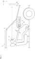
- a detection device 50 may be mounted on a movable body 10.
- the detection device 50 includes a camera 11 and a detector 15.
- the movable body 10 may include a 3D projection system 100.
- the 3D projection system 100 includes the detection device 50 and a 3D projector 12.
- Examples of the movable body in one or more embodiments of the present disclosure may include a vehicle, a vessel, and an aircraft.
- Examples of the vehicle may include an automobile, an industrial vehicle, a railroad vehicle, a community vehicle, and a fixed-wing aircraft traveling on a runway.
- Examples of the automobile may include a passenger vehicle, a truck, a bus, a motorcycle, and a trolley bus.
- Examples of the industrial vehicle may include an industrial vehicle for agriculture and an industrial vehicle for construction.
- Examples of the industrial vehicle may include a forklift and a golf cart.
- Examples of the industrial vehicle for agriculture may include a tractor, a cultivator, a transplanter, a binder, a combine, and a lawn mower.
- Examples of the industrial vehicle for construction may include a bulldozer, a scraper, a power shovel, a crane vehicle, a dump truck, and a road roller.
- Examples of the vehicle may include man-powered vehicles.
- the classification of the vehicle is not limited to the above examples.
- Examples of the automobile may include an industrial vehicle travelling on a road.
- One type of vehicle may fall within multiple classes.
- Examples of the vessel may include a jet ski, a boat, and a tanker.
- Examples of the aircraft may include a fixed-wing aircraft and a rotary-wing aircraft.
- the movable body 10 is a passenger vehicle.
- the movable body 10 is not limited to a passenger vehicle, but may be any of the above examples.
- the camera 11 may be attached to the movable body 10.
- the camera 11 captures an image of a driver 13 of the movable body 10.
- the image of the driver 13 includes a face (human face).
- the camera 11 may be attached at any position inside or outside the movable body 10.
- the camera 11 may be on a dashboard in the movable body 10.
- the camera 11 may be a visible light camera or an infrared camera.
- the camera 11 may function both as a visible light camera and an infrared camera.
- the camera 11 may include, for example, a charge-coupled device (CCD) image sensor or a complementary metal-oxide semiconductor (CMOS) image sensor.
- CCD charge-coupled device
- CMOS complementary metal-oxide semiconductor
- An image captured with the camera 11 is output to the detector 15.
- the detector 15 uses template matching to detect the position of an eye 5 of the driver 13 based on the captured image output from the camera 11.
- the camera 11 may output an image to the detector 15 for every frame.
- the detector 15 may detect the position of the eye 5 through template matching for every frame.
- the position of the eye 5 of the driver 13 may be the position of the pupil.
- Template matching is image processing of searching a target image for a position with the highest degree of matching with a template image.
- the detection device 50 uses a captured image 51 output from the camera 11 as a target image.
- a template image 52 includes the eye 5 of the driver 13 or a part of the face determined to have a relative positional relationship with the eye 5 of the driver 13.
- the template image 52 may include, as the eye 5 of the driver 13, the two eyes, the right eye alone, or the left eye alone.
- the facial part determined to have a relative positional relationship with the eye(s) 5 of the driver 13 may be, for example, the eyebrows or the nose.
- the template image 52 includes the two eyes as the eye(s) 5 of the driver 13.
- the structure that forms the basis of the present disclosure performs pupil position detection based on a captured image using the captured image including the pupils of the user.
- the pupil positions cannot be detected.
- the pupil positions cannot be detected based on an image of the user captured when the user's eyes are closed, such as when the user is blinking.
- the structure in an embodiment of the present disclosure uses template matching of searching the captured image 51 for a position with the highest degree of matching with the template image 52, and thus can search the captured image 51 for any position with the highest degree of matching using features other than the pupils in the template image 52 when the captured image 51 does not include pupils.
- the template image 52 is larger than the pupils.
- template matching involves less computation than pupil detection when each performed using the captured image 51 with the same size as the detection target. With such less computation, the detector 15 can output a detection result from template matching at a higher computation speed than a result from pupil detection.
- the template image 52 may be shaped in correspondence with the shape of the captured image 51.
- the template image 52 may be rectangular.
- the shape of the template image 52 may be or may not be similar to the shape of the captured image 51.
- the captured image 51 and the template image 52 are rectangular as illustrated in FIG. 2 .
- a detection result obtained by the detection device 50 may be coordinate information indicating the pupil positions of the eyes 5 (two eyes) of the driver 13.
- the coordinates of the position in the captured image 51 with the highest degree of matching with the template image 52 are determined through template matching.
- the coordinates of the matching position resulting from template matching may, for example, correspond to the coordinates of a representative position in the template image 52.
- the representative position in the template image 52 may be, for example, any one of the vertexes or the center of the template image 52.
- the relative coordinate positional relationship between the coordinates of the pupil positions in the template image 52 and the representative position in the template image 52 may be predefined.
- the coordinates and the predefined relative positional relationship can be used to determine coordinate information about the pupil positions in the captured image 51.
- coordinate information about the pupil positions of the eyes 5 being open can be obtained through estimation.
- the detection device 50 can determine coordinate information about the pupil positions although the driver 13 has the eyes 5 closed by, for example, blinking, allowing successive output of coordinate information without interruption.
- the detection device 50 may include, for example, a sensor.
- the sensor may be, for example, an ultrasonic sensor or an optical sensor.
- the camera 11 may detect the position of the head of the driver 13 with the sensor, and detect the positions of the eyes 5 of the driver 13 based on the position of the head.
- the camera 11 may detect the positions of the eyes 5 of the driver 13 as the coordinates in a 3D space using two or more sensors.
- the detection device 50 may output coordinate information about the detected pupil positions of the eyes 5 to the 3D projector 12.
- the 3D projector 12 may control an image to be projected based on the received coordinate information.
- the detection device 50 may output information indicating the pupil positions of the eyes 5 to the 3D projector 12 through wired or wireless communication.
- Wired communication may include, for example, communication using a controller area network (CAN).
- CAN controller area network
- the detection device 50 may include the detector 15 that is an external device.
- the camera 11 may output the captured image 51 to the external detector 15.
- the external detector 15 may detect the pupil positions of the eyes 5 of the driver 13 by template matching based on the image output from the camera 11.
- the external detector 15 may output the coordinate information about the detected pupil positions of the eyes 5 to the 3D projector 12.
- the 3D projector 12 may control an image to be projected based on the received coordinate information.
- the camera 11 may output the captured image to the external detector 15 through wired or wireless communication.
- the external detector 15 may output the coordinate information to the 3D projector 12 through wired or wireless communication.
- Wired communication may include, for example, communication using a CAN.
- the 3D projector 12 may be at any position inside or outside the movable body 10.
- the 3D projector 12 may be on the dashboard in the movable body 10.
- the 3D projector 12 emits image light toward a windshield 25.
- the windshield 25 reflects the image light emitted from the 3D projector 12.
- the image light reflected from the windshield 25 reaches an eye box 16.
- the eye box 16 is an area in a real space expected to include the eyes 5 of the driver 13 based on, for example, the body shape, posture, and changes in the posture of the driver 13.
- the eye box 16 may have any shape.
- the eye box 16 may include a planar or 3D area.
- the solid arrow in FIG. 1 indicates the traveling path of at least a part of the image light emitted from the 3D projector 12 to reach the eye box 16.
- the traveling path of the image light is also referred to as an optical path.
- the virtual image 14 is located on an extension of the path from the windshield 25 to the eyes 5 (on a straight line drawn with a dot-dash line in the figure).
- the extension is directed frontward from the movable body 10.
- the 3D projector 12 can function as a head-up display that allows the driver 13 to view the virtual image 14.
- the direction in which the eyes 5 of the driver 13 are aligned corresponds to x-direction.
- the vertical direction corresponds to y-direction.
- the imaging range of the camera 11 includes the eye box 16.
- the 3D projector 12 includes a 3D display device 17 and an optical element 18.
- the 3D projector 12 may also be referred to as an image display module.
- the 3D display device 17 may include a backlight 19, a display 20 including a display surface 20a, a barrier 21, and a controller 24.
- the 3D display device 17 may further include a communicator 22.
- the 3D display device 17 may further include a storage 23.
- the optical element 18 may include a first mirror 18a and a second mirror 18b. At least one of the first mirror 18a or the second mirror 18b may have optical power. In the present embodiment, the first mirror 18a is a concave mirror having optical power. The second mirror 18b is a plane mirror.
- the optical element 18 may function as a magnifying optical system that magnifies an image displayed by the 3D display device 17.
- the arrowed dot-dash line in FIG. 3 indicates the traveling path of at least a part of image light emitted from the 3D display device 17 to be reflected from the first mirror 18a and the second mirror 18b and then exit the 3D projector 12.
- the image light exiting from the 3D projector 12 reaches the windshield 25, is reflected from the windshield 25, and then reaches the eyes 5 of the driver 13.
- the driver 13 can view the image displayed by the 3D display device 17.
- the optical element 18 and the windshield 25 are designed to cause image light emitted from the 3D display device 17 to reach the eyes 5 of the driver 13.
- the optical element 18 and the windshield 25 may be included in an optical system.
- the optical system allows the image light emitted from the 3D display device 17 to travel along the optical path indicated by the dot-dash line and reach the eyes 5 of the driver 13.
- the optical system may control the traveling direction of image light to enlarge or reduce an image viewable to the driver 13.
- the optical system may control the traveling direction of image light to change the shape of the image viewable by the driver 13 based on a predetermined matrix.
- the optical element 18 may have a structure different from the illustrated structure.
- the optical element 18 may include a concave mirror, a convex mirror, or a plane mirror.
- the concave mirror or the convex mirror may be at least partially spherical or aspherical.
- the optical element 18 may be one element or may include three or more elements, instead of two elements.
- the optical element 18 may include a lens instead of or in addition to a mirror.
- the lens may be a concave lens or a convex lens.
- the lens may be at least partially spherical or aspherical.
- the backlight 19 is more away on the optical path of image light viewed from the driver 13 than the display 20 and the barrier 21.
- the backlight 19 emits light toward the barrier 21 and the display 20. At least a part of the light emitted from the backlight 19 travels along the optical path indicated by the dot-dash line and reaches the eyes 5 of the driver 13.
- the backlight 19 may include a light-emitting diode (LED) or a light emitter such as an organic electroluminescence (EL) element and an inorganic EL element.
- the backlight 19 may have any structure that allows control of the light intensity and the light intensity distribution.
- the display 20 includes a display panel.
- the display 20 may be, for example, a liquid-crystal device such as a liquid-crystal display (LCD).
- the display 20 includes a transmissive liquid-crystal display panel.
- the display 20 is not limited to this example and may be any of various display panels.
- the display 20 includes multiple pixels and controls the transmittance of light from the backlight 19 incident on each pixel to emit image light reaching the eyes 5 of the driver 13.
- the driver 13 views an image formed with the image light emitted from each pixel in the display 20.
- the barrier 21 defines the traveling direction of incident light.
- the barrier 21 blocks or attenuates a part of light emitted from the backlight 19 and transmits another of the light to the display 20.
- the display 20 emits incident light traveling in a direction defined by the barrier 21 as image light traveling in the same direction.
- the barrier 21 blocks or attenuates a part of image light emitted from the display 20 and transmits another part of the image light toward the eyes 5 of the driver 13.
- the barrier 21 controls the traveling direction of image light.
- the barrier 21 allows a part of image light emitted from the display 20 to reach either the left eye 5L or the right eye 5R (refer to FIG. 4 ) of the driver 13, and to allow another part of the image light to reach the other of the left eye 5L or the right eye 5R of the driver 13.
- the barrier 21 directs at least a part of image light toward the left eye 5L of the driver 13 and toward the right eye 5R of the driver 13.
- the left eye 5L is also referred to as a first eye, and the right eye 5R as a second eye.
- the barrier 21 is located between the backlight 19 and the display 20. In other words, light emitted from the backlight 19 first enters the barrier 21 and then enters the display 20.
- the barrier 21 defines the traveling direction of image light to allow each of the left eye 5L and the right eye 5R of the driver 13 to receive different image light. Each of the left eye 5L and the right eye 5R of the driver 13 can thus view a different image.
- the display 20 includes, on the display surface 20a, left-eye viewing areas 201L viewable by the left eye 5L of the driver 13 and right-eye viewing areas 201R viewable by the right eye 5R of the driver 13.
- the display 20 displays a parallax image including left-eye images viewable by the left eye 5L of the driver 13 and right-eye images viewable by the right eye 5R of the driver 13.
- a parallax image refers to an image projected to the left eye 5L and the right eye 5R of the driver 13 to generate parallax between the two eyes of the driver 13.
- the display 20 displays left-eye images on the left-eye viewing areas 201L and right-eye images on the right-eye viewing areas 201R.
- the display 20 displays a parallax image on the left-eye viewing areas 201L and the right-eye viewing areas 201R.
- the left-eye viewing areas 201L and the right-eye viewing areas 201R are arranged in u-direction indicating a parallax direction.
- the left-eye viewing areas 201L and the right-eye viewing areas 201R may extend in v-direction orthogonal to the parallax direction, or in a direction inclined with respect to v-direction at a predetermined angle.
- the left-eye viewing areas 201L and the right-eye viewing areas 201R may be arranged alternately in a predetermined direction including a component in the parallax direction.
- the pitch between the alternately arranged left-eye viewing areas 201L and right-eye viewing areas 201R is also referred to as a parallax image pitch.
- the left-eye viewing areas 201L and the right-eye viewing areas 201R may be spaced from each other or adjacent to each other.
- the display 20 may further include a display area on the display surface 20a for displaying a planar image.
- a planar image is an image that generates no parallax between the eyes 5 of the driver 13 and is not viewed stereoscopically.
- the barrier 21 includes open areas 21b and light-blocking surfaces 21a. With the barrier 21 nearer the driver 13 than the display 20 on the optical path of image light, the barrier 21 controls the transmittance of image light emitted from the display 20.
- the open areas 21b transmit light entering the barrier 21 from the display 20.
- the open areas 21b may transmit light with a transmittance of a first predetermined value or greater.
- the first predetermined value may be, for example, 100% or a value close to 100%.
- the light-blocking surfaces 21a block light entering the barrier 21 from the display 20.
- the light-blocking surfaces 21a may transmit light with a transmittance of a second predetermined value or less.
- the second predetermined value may be, for example, 0% or a value close to 0%.
- the first predetermined value is greater than the second predetermined value.
- the open areas 21b and the light-blocking surfaces 21a are arranged alternately in u-direction indicating the parallax direction.
- the boundaries between the open areas 21b and the light-blocking surfaces 21a may extend in v-direction orthogonal to the parallax direction as illustrated in FIG. 4 , or in a direction inclined with respect to v-direction at a predetermined angle.
- the open areas 21b and the light-blocking surfaces 21a may be arranged alternately in a predetermined direction including a component in the parallax direction.
- the barrier 21 is more away from the driver 13 than the display 20 on the optical path of image light.
- the barrier 21 controls the transmittance of light directed from the backlight 19 to the display 20.
- the open areas 21b transmit light directed from the backlight 19 to the display 20.
- the light-blocking surfaces 21a block light directed from the backlight 19 to the display 20. This structure allows light entering the display 20 to travel in a predetermined direction.
- the barrier 21 can control a part of image light to reach the left eye 5L of the driver 13, and another part of the image light to reach the right eye 5R of the driver 13.
- the barrier 21 may include a liquid crystal shutter.
- the liquid crystal shutter can control the transmittance of light in accordance with a voltage applied.
- the liquid crystal shutter may include multiple pixels and control the transmittance of light for each pixel.
- the liquid crystal shutter can form an area with high light transmittance or an area with low light transmittance in an intended shape.
- the open areas 21b in the barrier 21 including the liquid crystal shutter may have a transmittance of the first predetermined value or greater.
- the light-blocking surfaces 21a in the barrier 21 including the liquid crystal shutter may have a transmittance of the second predetermined value or smaller.
- the first predetermined value may be greater than the second predetermined value.
- the ratio of the second predetermined value to the first predetermined value may be set to 1/100 in one example.
- the ratio of the second predetermined value to the first predetermined value may be set to 1/1000 in another example.
- the barrier 21 including the open areas 21b and the light-blocking surfaces 21a that can shift is also referred to as
- the controller 24 controls the display 20.
- the controller 24 may control the barrier 21.
- the controller 24 may control the backlight 19.
- the controller 24 obtains coordinate information about the pupil positions of the eyes 5 of the driver 13 from the detection device 50, and controls the display 20 based on the coordinate information.
- the controller 24 may control at least one of the barrier 21 or the backlight 19 based on the coordinate information.
- the controller 24 may receive an image output from the camera 11 and detect the eyes 5 of the driver 13 based on the received image. In other words, the controller 24 may have the same function as and may serve as the detector 15.
- the controller 24 may control the display 20 based on the detected pupil positions of the eyes 5.
- the controller 24 can control at least one of the barrier 21 or the backlight 19 based on the detected pupil positions of the eyes 5.
- the controller 24 and the detector 15 may be, for example, processors.
- the controller 24 and the detector 15 may each include one or more processors.
- the processors may include a general-purpose processor that reads a specific program to perform a specific function, and a processor dedicated to specific processing.
- the dedicated processor may include an application-specific integrated circuit (ASIC).
- the processors may include a programmable logic device (PLD).
- the PLD may include a field-programmable gate array (FPGA).
- the controller 24 and the detector 15 may each be a system-on-a-chip (SoC) or a system in a package (SiP) in which one or more processors cooperate with other components.
- SoC system-on-a-chip
- SiP system in a package
- the communicator 22 may include an interface that can communicate with an external device.
- the external device may include, for example, the detection device 50.
- the external device may provide, for example, image information to be displayed on the display 20.
- the communicator 22 may obtain various sets of information from the external device such as the detection device 50 and output the information to the controller 24.
- the interface that can perform communication in one or more embodiments of the present disclosure may include, for example, a physical connector and a wireless communication device.
- the physical connector may include an electric connector for transmission with electric signals, an optical connector for transmission with optical signals, and an electromagnetic connector for transmission with electromagnetic waves.
- the electric connector may include a connector complying with IEC 60603, a connector complying with the universal serial bus (USB) standard, and a connector used for an RCA terminal.
- USB universal serial bus
- the electric connector may include a connector used for an S terminal specified by EIAJ CP-121aA or a connector used for a D terminal specified by EIAJ RC-5237.
- the electric connector may include a connector complying with the High-Definition Multimedia Interface (HDMI, registered trademark) standard or a connector used for a coaxial cable including a British Naval Connector, also known as, for example, a Baby-series N Connector (BNC).
- the optical connector may include a connector complying with IEC 61754.
- the wireless communication device may include a wireless communication device complying with the Bluetooth (registered trademark) standard and a wireless communication device complying with other standards including IEEE 8021a.
- the wireless communication device includes at least one antenna.
- the storage 23 may store various sets of information or programs for causing the components of the 3D display device 17 to operate.
- the storage 23 may include, for example, a semiconductor memory.
- the storage 23 may function as a work memory for the controller 24.
- the controller 24 may include the storage 23.
- light emitted from the backlight 19 passes through the barrier 21 and the display 20 to reach the eyes 5 of the driver 13.
- the broken lines indicate the paths traveled by light from the backlight 19 to reach the eyes 5.
- the light through the open areas 21b in the barrier 21 to reach the right eye 5R passes through the right-eye viewing areas 201R in the display 20. In other words, light through the open areas 21b allows the right eye 5R to view the right-eye viewing areas 201R.
- the light through the open areas 21b in the barrier 21 to reach the left eye 5L passes through the left-eye viewing areas 201L in the display 20. In other words, light through the open areas 21b allows the left eye 5L to view the left-eye viewing areas 201L.
- the display 20 displays left-eye images on the left-eye viewing areas 201L and right-eye images on the right-eye viewing areas 201R.
- the barrier 21 allows image light for the left-eye images to reach the left eye 5L and image light for the right-eye images to reach the right eye 5R.
- the open areas 21b allow image light for the left-eye images to reach the left eye 5L of the driver 13 and image light for the right-eye images to reach the right eye 5R of the driver 13.
- the 3D display device 17 with this structure can project a parallax image to the two eyes of the driver 13.
- the driver 13 views the parallax image with the left eye 5L and the right eye 5R to view the image stereoscopically.
- the open areas 21b in the barrier 21 Light through the open areas 21b in the barrier 21 is emitted through the display surface 20a of the display 20 as image light and reaches the windshield 25 through the optical element 18.
- the image light is reflected from the windshield 25 and reaches the eyes 5 of the driver 13.
- the second virtual image 14b corresponds to an image appearing on the display surface 20a.
- the open areas 21b and the light-blocking surfaces 21a in the barrier 21 form a first virtual image 14a in front of the windshield 25 and more away in the negative z-direction than the second virtual image 14b.
- the driver 13 can view an image with the display 20 appearing to be at the position of the second virtual image 14b and the barrier 21 appearing to be at the position of the first virtual image 14a.
- the 3D display device 17 emits image light for the image appearing on the display surface 20a in a direction defined by the barrier 21.
- the optical element 18 allows the image light to travel toward the windshield 25.
- the optical element 18 can reflect or refract the image light.
- the windshield 25 reflects the image light and directs the light toward the eyes 5 of the driver 13.
- the image light entering the eyes 5 of the driver 13 causes the driver 13 to view a parallax image as the virtual image 14.
- the driver 13 views the virtual image 14 stereoscopically.
- An image of the virtual image 14 corresponding to the parallax image is also referred to as a parallax virtual image.
- a parallax virtual image is a parallax image projected through the optical system.
- An image of the virtual image 14 corresponding to the planar image is also referred to as a planar virtual image.
- a planar virtual image is a planar image projected through the optical system.
- the detector 15 may use the entire range of the captured image 51 as a search range in template matching.
- the detector 15 may use a part of the captured image 51 as the search range in template matching. Apart of the search range may include the face of the driver 13 in the captured image 51.
- the detector 15 detects the face of the driver 13 in the captured image 51 captured with the camera 11 and defines a search range with a predetermined size (smaller than the entire range of the captured image 51) including the detected face.
- the detector 15 may perform template matching by searching the defined search range with the template image 52.
- the search range with the template image 52 is smaller than the entire range of the captured image 51.
- the template matching involves less computation. With such less computation, the detector 15 can output a detection result from template matching at a higher computation speed.
- the detector 15 generates the template image 52 based on the captured image 51 captured with the camera before starting the search.
- the detector 15 may perform pupil detection in the captured image 51 and use the predetermined peripheral area including the detected pupils as the template image 52.
- the predetermined peripheral area to be generated as the template image 52 may be, for example, an area corresponding to the eye box 16 in the 3D projector 12.
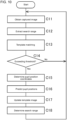
- the detection device 50 may perform, for example, the template image generation process in the flowchart of FIG. 5 .
- the detection device 50 may start the template image generation process when, for example, the 3D projection system 100 is activated (powered on).
- the camera 11 first captures an image to obtain a captured image 51 and outputs the image to the detector 15.
- the captured image 51 captured with the camera 11 includes, for example, the face of the driver 13 seated in a seat in the movable body 10.
- the detector 15 extracts a first area including the eye box 16 from the captured image 51.
- the detector 15 performs face detection on the extracted first area to determine whether the face of the driver is detected.
- the processing advances to step A4.
- the processing returns to step A1, in which an image is captured again with the camera 11.
- step A4 the detector 15 extracts a second area containing the detected face from the first area.
- step A5 the detector 15 performs pupil detection on the second area to determine whether pupils are detected.
- the processing advances to step A6.
- step A6 the processing returns to step A1, in which an image is captured again with the camera 11.
- step A6 the detector 15 extracts a pupil peripheral area including the detected pupils as a template image 52.
- the template image generation process ends.
- the detector 15 may store the extracted template image 52, for example, into a storage area included in the detector 15 or into the storage 23.
- the detector 15 may extract, for example, a pupil peripheral area with the same size as the eye box 16 as the template image 52.
- the detector 15 may also store the relative coordinate positional relationship between each representative position and the corresponding pupil positions on the template image 52, together with the template image 52.
- the template image 52 may be temporarily stored into the storage area in the detector 15 while the 3D projection system 100 is activated.
- the template image 52 may be, for example, associated with the imaged driver 13 and stored into the storage 23.
- the template image 52 stored in the storage 23 can be subsequently read from the storage 23 by the detector 15 at, for example, subsequent activation of the 3D projection system 100. This eliminates the template image generation process.
- the detector 15 can perform the template image generation process again to update (rewrite) the template image 52 stored in the storage 23.
- the template matching process will be described with reference to a flowchart.
- the detection device 50 may perform, for example, the template matching process in the flowchart of FIG. 6 .
- the detection device 50 may perform, for example, the template image generation process in response to activation of the 3D projection system 100, and start the template matching process after the template image generation process ends.
- the detection device 50 may start the template matching process in response to activation of the 3D projection system 100.
- step B1 the detector 15 first obtains the captured image 51 from the camera 11.
- step B2 the detector 15 extracts the area surrounding the position at which the template image 52 is extracted from the captured image 51 as a search range.
- the coordinates of the position at which the template image 52 is extracted may be associated with the template image 52 and be stored.
- step B3 the detector 15 performs template matching for the search range using the template image 52.
- the detector 15 determines a position with the highest degree of matching with the template image 52 within the search range and the degree of matching by template matching.
- step B4 the detector 15 determines whether the determined degree of matching is greater than or equal to a threshold. When the value is greater than or equal to the threshold, the processing advances to step B5.
- step B5 the detector 15 determines the coordinates of the pupil positions in the captured image 51 based on the coordinates of the position with the highest degree of matching with the template image 52 within the search range and the predefined relative coordinate positional relationship, and ends the template matching process.
- the coordinate information about the determined pupil positions is output from the detection device 50 to the 3D projector 12.
- the controller 24 controls the parallax image displayed on the display 20 based on the coordinate information about the pupil positions obtained from the detection device 50.
- the driver's seat of the movable body 10 is, for example, movable in the front-rear direction.
- the posture of the driver 13 may also change during the operation of the movable body 10.
- the front or rear position of the driver's seat or the posture of the driver 13 may change.
- the face of the driver 13 may then move in z-direction.
- the face of the driver 13 moves in the positive z-direction
- the face of the driver 13 is captured to be smaller in the captured image 51 than before the movement.
- the face of the driver 13 moves in the negative z-direction
- the face of the driver 13 is captured to be larger in the captured image 51 than before the movement.
- the template image 52 is to undergo a scaling process, and then template matching is to be performed using the resultant template image 52.
- multiple template images 52 with different enlargement factors may be used in template matching.
- multiple template images 52 with different reduction factors may be used in template matching.
- the template matching processes in another example will be described with reference to a flowchart.
- the detection device 50 may perform, for example, a template matching process in the flowchart of FIG. 7 .
- the detection device 50 may perform, for example, the template image generation process in response to activation of the 3D projection system 100, and start the template matching process after the template image generation process ends.
- the detection device 50 may start the template matching process in response to activation of the 3D projection system 100.
- step C5 the detector 15 performs a scaling process on the template images using multiple scaling factors for the template images 52.
- the detector 15 performs template matching using each template image 52 resulting from the scaling process.
- the detection device 50 does not detect directions of changes in the posture of the driver 13, and performs both enlargement and reduction processes as the scaling process.
- the detector 15 performs template matching using the multiple template images 52 to determine the template image 52 with the highest degree of matching.
- step C6 the detector 15 estimates the position of the driver in z-direction based on the scaling factor of the template image 52 with the highest degree of matching.
- step C7 after determining the coordinates of the pupil positions in the captured image 51 in the same or similar manner to step B5, the pupil position coordinates are corrected based on the estimated position in z-direction, and the template matching process ends.
- the coordinate information about the determined pupil positions is output from the detection device 50 to the 3D projector 12.
- a 3D projection system 100A in another example will be described.
- a detection device 50A includes a camera 11, a detector 15A, and a predictor 30.
- the components of the 3D projection system 100A are the same as or similar to the components of the 3D projection system 100 described above except the detection device 50A.
- the components of the 3D projection system 100A are thus denoted with the same reference numerals as the corresponding components and will not be described in detail.
- the predictor 30 predicts the positions of the eyes 5 at a time later than the current time based on multiple positions of the eyes 5 detected by the detector 15.
- the positions of the eyes 5 in the present embodiment may also be coordinate information indicating the pupil positions of the eyes 5 of the driver 13 as described above.
- the multiple positions of the eyes 5 include the positions of the eyes 5 at different detection times.
- the predictor 30 may predict future positions of the eyes 5 using multiple sets of data about detection time and coordinate information, and output the future positions as predicted positions.
- the detector 15A may store coordinate information and detection time as data for prediction, for example, into the storage area in the detector 15, the storage area in the predictor 30, or the storage 23 sequentially.
- the future positions of the eyes 5 refer to the positions in the future with respect to the multiple sets of data stored for prediction.
- the method of predicting the positions of the eyes 5 used by the predictor 30 may use, for example, a prediction function.
- the prediction function is derived from multiple sets of data stored for prediction.
- the prediction function uses a function formula with coefficients determined in advance by experiment or other means.
- the prediction function may be stored in the storage area in the detector 15A, the storage area in the predictor 30, or the storage 23.
- the prediction function may be updated every time when the predictor 30 predicts the positions of the eyes 5.
- the predictor 30 inputs the future time to be predicted into the prediction function and outputs the coordinate information about the positions of the eyes 5 (predicted positions) at the time.
- the future time to be predicted is the time at which the next template matching is to be performed. This may be, for example, the time when the next frame is input from the camera 11.
- the detector 15A may search a part of the captured image 51 as a search range in template matching.
- the detector 15A may search an area including the positions of the eyes 5 predicted by the predictor 30 defined as a search range in template matching.
- the detector 15A defines an area including the predicted positions output by the predictor 30 as a prediction area in the captured image 51, and defines the prediction range as a search range in template matching.
- the prediction range including the predicted positions may be smaller than the captured image 51 and larger than the template image 52, and may contain the predicted positions within the area.
- the prediction range may be an area in which the center coordinates of the prediction range match the coordinates of the predicted positions.
- the shape and size of the search range in template matching in the present embodiment may have, for example, similarity to the template image.
- the detector 15A performs template matching in such an area as the search range.
- the template matching in the present embodiment is the same as or similar to the template matching described above except the search range.
- a position with the highest degree of matching with the template image 52 is searched in the prediction range as the search range.
- the detection result may be the coordinate information indicating the pupil positions of the eyes 5 of the driver 13.
- the prediction area as the search range in the present embodiment includes the predicted positions output from the predictor 30.
- the pupil positions of the eyes 5 are thus highly likely to be included in the search range after the search range is set smaller.
- the template matching involves less computation. With such less computation, the detector 15A can output a detection result from template matching at a higher computation speed.
- the predictor 30 may further calculate the change rate of the positions of the eyes 5 based on the multiple positions of the eyes 5 detected by the detector 15A.
- sets of coordinate information and detection time are stored as prediction data.
- Multiple sets of prediction data are used to calculate the change rate of the positions of the eyes 5.
- the traveling distance from the positions of the eyes 5 can be calculated based on the difference between two sets of prediction data using the coordinate information.
- the time can be calculated from the detection time.
- the change rate of the positions of the eyes 5 can thus be calculated.
- the components in x- and y-directions can be calculated based on the traveling distance and the change rate of the positions of the eyes 5.
- the detector 15A adjusts the size of the search range in template matching in accordance with the change rate calculated by the predictor 30.
- the change rate calculated by the predictor 30 is large, the moving distance of the positions of the eyes 5 can be predicted to be large.
- the traveling distance from the positions of the eyes 5 is estimated to be greater in the direction of the larger component of the change rate.
- the search range in template matching can be defined as a small area by predicting the positions of the eyes 5.
- the detector 15A may widen the area including the predicted positions in the direction of a larger component of the change rate. The detector 15A performs template matching in this widened area as the search range.
- the template matching process including pupil position prediction will be described with reference to a flowchart.
- the detection device 50A may perform, for example, the template matching process in the flowchart of FIG. 9 .
- the detection device 50A may perform, for example, the template image generation process in response to activation of the 3D projection system 100A, and start the template matching process after the template image generation process ends.
- the detection device 50A may start the template matching process in response to activation of the 3D projection system 100A.
- step B 11 the detector 15A first obtains the captured image 51 from the camera 11.
- step B12 the detector 15A extracts the search range from the captured image 51.
- the search range extracted in step B12 is the search range determined in step B17 (described later).
- the area surrounding the position at which the template image 52 is extracted may be used as the search range.
- step B13 the detector 15A performs template matching in the search range using the template image 52.
- the detector 15A determines a position with the highest degree of matching with the template image 52 within the search range and its degree of matching by template matching.
- step B 14 the detector 15A determines whether the determined degree of matching is greater than or equal to the threshold.
- step B15 When the value is greater than or equal to the threshold, the processing advances to step B15. When the value is less than the threshold, the processing returns to step B1 and performs imaging with the camera 11 again.
- the detector 15A determines the coordinates of the pupil positions in the captured image 51 based on the coordinates of the position with the highest degree of matching with the template image 52 within the search range and the predefined relative coordinate positional relationship.
- the coordinate information about the determined pupil positions is output from the detection device 50 to the 3D projector 12.
- the controller 24 controls the parallax image displayed on the display 20 based on the coordinate information about the pupil positions obtained from the detection device 50.
- step B16 the predictor 30 predicts future pupil positions and outputs the positions as predicted positions.
- the predictor 30 updates the prediction function based on, for example, the latest data for prediction, which is a set of coordinate information about the pupil positions determined in step B15 and the detection time, and the past data stored for prediction.
- the predictor 30 predicts the pupil positions using the updated prediction function and outputs the predicted positions.
- step B17 the detector 15A determines the area including the predicted positions output from the predictor 30 as the search range. The processing returns to step B11.
- the face of the driver 13 may move back and forth.
- the face of the driver 13 may tilt.
- the face of the driver 13 in the captured image 51 appears larger or smaller, similarly to when the image is processed for enlargement or reduction.
- the face of the driver 13 in the captured image is similar to that in the rotation process.
- the detector 15A compares the predicted positions with the latest pupil positions. When the comparison result indicates that, for example, the interocular distance has changed, the detector 15A updates the template image 52 to a template image 52 with a scaling factor corresponding to the interocular distance.
- the detector 15A may, for example, pre-generate multiple template images 52 with different enlargement factors and multiple template images 52 with different reduction factors through the scaling process, and select the template image 52 corresponding to the interocular distance. With the predictor 30 predicting the pupil position of the left eye and the pupil position of the right eye, the detector 15A may detect the change in the interocular distance by comparing the latest pupil position of the left eye and the latest pupil position of the right eye.
- the detector 15A updates the template image 52 to a template image 52 with a rotation angle corresponding to the tilt change.
- the detector 15A may pre-generate, for example, multiple template images 52 with different rotation angles through the rotation process, and select the template image 52 corresponding to the tilt change.
- the detector 15A may detect the tilt change from the change in the position in y-direction by comparing the latest pupil position of the left eye and the latest pupil position of the right eye.
- the respective pupil positions in y-direction (y-coordinates) of the left and right eyes change in different directions.
- the pupil position in y-direction of the left eye changing upward and the pupil position in y-direction of the right eye changing downward correspond to a tilt change.
- the detector 15A may calculate the rotation angle based on the magnitude of the position change of the left and right eyes in y-direction.
- the detection device 50A may perform, for example, the template matching process in the flowchart of FIG. 10 .
- the detector 15A first obtains the captured image 51 from the camera 11.
- the detector 15A extracts the search range from the captured image 51.
- the search range extracted in step C12 is the search range determined in step C18 (described later).
- the area surrounding the position at which the template image 52 is extracted may be used as the search range.
- the detector 15A performs template matching in the search range using the updated template image 52.
- the template image 52 is the template image 52 updated in step C17 (described later).
- the detector 15A determines a position with the highest degree of matching with the template image 52 within the search range and its degree of matching by template matching.
- step C14 the detector 15A determines whether the determined degree of matching is greater than or equal to the threshold.
- the processing advances to step C15.
- the processing returns to step C11 and performs imaging with the camera 11 again.
- step C15 the detector 15A determines the coordinates of the pupil positions in the captured image 51 based on the coordinates of the position with the highest degree of matching with the template image 52 within the search range and the predefined relative coordinate positional relationship.
- the coordinate information about the determined pupil positions is output from the detection device 50 to the 3D projector 12.
- the controller 24 controls the parallax image displayed on the display 20 based on the coordinate information about the pupil positions obtained from the detection device 50.
- step C16 the predictor 30 predicts future pupil positions and outputs the position as predicted positions.
- step C17 the detector 15A updates the template image 52.
- the detector 15A compares the predicted positions with the latest pupil positions and updates the template image 52 to a template image 52 that has at least undergone the scaling process or the rotation process in accordance with the comparison result.
- step C18 the detector 15A determines the area including the predicted positions output from the predictor 30 as the search range. The processing returns to step C11.
- the structure is not limited to the structure described in the above embodiments, but may be varied or altered.
- the functions of the components are reconfigurable unless any contradiction arises. Multiple components may be combined into a single unit, or a single component may be divided into separate units.
- the first, the second, or others are identifiers for distinguishing the components.
- the identifiers of the components distinguished with the first, the second, and others in the present disclosure are interchangeable.
- the first eye can be interchangeable with the second eye.
- the identifiers are to be interchanged together.
- the components for which the identifiers are interchanged are also to be distinguished from one another.
- the identifiers may be eliminated.
- the components without such identifiers can be distinguished with reference numerals.
- the identifiers such as the first and the second in the present disclosure alone should not be used to determine the order of components or to suggest the existence of smaller or larger number identifiers.
- x-axis, y-axis, and z-axis are used for ease of explanation and may be interchangeable with one another.
- the orthogonal coordinate system including x-axis, y-axis, and z-axis is used to describe the structures according to the present disclosure.
- the positional relationship between the components in the present disclosure is not limited to being orthogonal.
- a detection device includes a camera and a detector.
- the camera captures an image of a human face.
- the detector detects a position of a human eye based on the captured image output from the camera by template matching.
- an image display system includes a display, a barrier, a camera, a detector, and a controller.
- the display displays a parallax image to be projected to two human eyes through an optical system.
- the barrier defines a traveling direction of image light for the parallax image to generate parallax between the two human eyes.
- the camera captures an image of a human face.
- the detector detects positions of the two human eyes based on the captured image output from the camera by template matching.
- the controller controls the display based on the positions of the two human eyes detected by the detector.
- the detection device and the image display system allow processing involving less computation and successive detection.
Landscapes
- Engineering & Computer Science (AREA)
- Multimedia (AREA)
- Physics & Mathematics (AREA)
- General Physics & Mathematics (AREA)
- Theoretical Computer Science (AREA)
- Health & Medical Sciences (AREA)
- General Health & Medical Sciences (AREA)
- Ophthalmology & Optometry (AREA)
- Human Computer Interaction (AREA)
- Computer Vision & Pattern Recognition (AREA)
- Signal Processing (AREA)
- Image Analysis (AREA)
Abstract
Description
- The present disclosure relates to a detection device and an image display module.
- A known technique is described in, for example, Patent Literature 1.
- Patent Literature 1:
Japanese Unexamined Patent Application Publication No. 2001-166259 - In one embodiment of the present disclosure, a detection device includes a camera and a detector. The camera captures an image of a human face. The detector detects a position of a human eye based on the captured image output from the camera by template matching.
- In one embodiment of the present disclosure, an image display system includes a display, a barrier, a camera, a detector, and a controller. The display displays a parallax image to be projected to two human eyes through an optical system. The barrier defines a traveling direction of image light for the parallax image to generate parallax between the two human eyes. The camera captures an image of a human face. The detector detects positions of the two human eyes based on the captured image output from the camera by template matching. The controller controls the display based on the positions of the two human eyes detected by the detector.
- The objects, features, and advantages of the present disclosure will become more apparent from the following detailed description and the drawings.
-
FIG. 1 is a schematic diagram of an example movable body incorporating a detection device. -
FIG. 2 is a schematic diagram describing template matching. -
FIG. 3 is a schematic diagram of an example three-dimensional (3D) projection system. -
FIG. 4 is a schematic diagram describing the relationship between the eyes of a driver, a display, and a barrier. -
FIG. 5 is a flowchart of an example template image generation process performed by the detection device. -
FIG. 6 is a flowchart of an example template matching process performed by the detection device. -
FIG. 7 is a flowchart of another example template matching process performed by the detection device. -
FIG. 8 is a schematic diagram of another example 3D projection system. -
FIG. 9 is a flowchart of another example template matching process performed by the detection device. -
FIG. 10 is a flowchart of another example template matching process performed by the detection device. - The structure that forms the basis of the present disclosure obtains, when detecting the positions of the eyes of a user, positional data indicating the positions of the pupils using an image of the eyes of the user captured with a camera. For example, a three-dimensional (3D) display device displays an image on a display to allow the left and right eyes of the user to view the corresponding images based on the positions of the pupils indicated by the positional data (e.g., Patent Literature 1).
- An embodiment of the present disclosure will now be described in detail with reference to the drawings. The drawings used herein are schematic and are not drawn to scale relative to the actual size of each component.
- As illustrated in
FIG. 1 , adetection device 50 according to one embodiment of the present disclosure may be mounted on amovable body 10. Thedetection device 50 includes acamera 11 and adetector 15. Themovable body 10 may include a3D projection system 100. The3D projection system 100 includes thedetection device 50 and a3D projector 12. - Examples of the movable body in one or more embodiments of the present disclosure may include a vehicle, a vessel, and an aircraft. Examples of the vehicle may include an automobile, an industrial vehicle, a railroad vehicle, a community vehicle, and a fixed-wing aircraft traveling on a runway. Examples of the automobile may include a passenger vehicle, a truck, a bus, a motorcycle, and a trolley bus. Examples of the industrial vehicle may include an industrial vehicle for agriculture and an industrial vehicle for construction. Examples of the industrial vehicle may include a forklift and a golf cart. Examples of the industrial vehicle for agriculture may include a tractor, a cultivator, a transplanter, a binder, a combine, and a lawn mower. Examples of the industrial vehicle for construction may include a bulldozer, a scraper, a power shovel, a crane vehicle, a dump truck, and a road roller. Examples of the vehicle may include man-powered vehicles. The classification of the vehicle is not limited to the above examples. Examples of the automobile may include an industrial vehicle travelling on a road. One type of vehicle may fall within multiple classes. Examples of the vessel may include a jet ski, a boat, and a tanker. Examples of the aircraft may include a fixed-wing aircraft and a rotary-wing aircraft.
- In the example described below, the
movable body 10 is a passenger vehicle. Themovable body 10 is not limited to a passenger vehicle, but may be any of the above examples. Thecamera 11 may be attached to themovable body 10. Thecamera 11 captures an image of adriver 13 of themovable body 10. The image of thedriver 13 includes a face (human face). Thecamera 11 may be attached at any position inside or outside themovable body 10. For example, thecamera 11 may be on a dashboard in themovable body 10. - The
camera 11 may be a visible light camera or an infrared camera. Thecamera 11 may function both as a visible light camera and an infrared camera. Thecamera 11 may include, for example, a charge-coupled device (CCD) image sensor or a complementary metal-oxide semiconductor (CMOS) image sensor. - An image captured with the
camera 11 is output to thedetector 15. Thedetector 15 uses template matching to detect the position of aneye 5 of thedriver 13 based on the captured image output from thecamera 11. Thecamera 11 may output an image to thedetector 15 for every frame. Thedetector 15 may detect the position of theeye 5 through template matching for every frame. The position of theeye 5 of thedriver 13 may be the position of the pupil. Template matching is image processing of searching a target image for a position with the highest degree of matching with a template image. Thedetection device 50 according to an embodiment of the present disclosure uses a capturedimage 51 output from thecamera 11 as a target image. Atemplate image 52 includes theeye 5 of thedriver 13 or a part of the face determined to have a relative positional relationship with theeye 5 of thedriver 13. Thetemplate image 52 may include, as theeye 5 of thedriver 13, the two eyes, the right eye alone, or the left eye alone. The facial part determined to have a relative positional relationship with the eye(s) 5 of thedriver 13 may be, for example, the eyebrows or the nose. In the example ofFIG. 2 , thetemplate image 52 includes the two eyes as the eye(s) 5 of thedriver 13. - The structure that forms the basis of the present disclosure performs pupil position detection based on a captured image using the captured image including the pupils of the user. With a captured image that does not include pupils, the pupil positions cannot be detected. For example, the pupil positions cannot be detected based on an image of the user captured when the user's eyes are closed, such as when the user is blinking. The structure in an embodiment of the present disclosure uses template matching of searching the captured
image 51 for a position with the highest degree of matching with thetemplate image 52, and thus can search the capturedimage 51 for any position with the highest degree of matching using features other than the pupils in thetemplate image 52 when the capturedimage 51 does not include pupils. Thetemplate image 52 is larger than the pupils. Thus, template matching involves less computation than pupil detection when each performed using the capturedimage 51 with the same size as the detection target. With such less computation, thedetector 15 can output a detection result from template matching at a higher computation speed than a result from pupil detection. - The
template image 52 may be shaped in correspondence with the shape of the capturedimage 51. For the capturedimage 51 being rectangular, thetemplate image 52 may be rectangular. The shape of thetemplate image 52 may be or may not be similar to the shape of the capturedimage 51. In the example described below, the capturedimage 51 and thetemplate image 52 are rectangular as illustrated inFIG. 2 . - A detection result obtained by the
detection device 50 may be coordinate information indicating the pupil positions of the eyes 5 (two eyes) of thedriver 13. The coordinates of the position in the capturedimage 51 with the highest degree of matching with thetemplate image 52 are determined through template matching. The coordinates of the matching position resulting from template matching may, for example, correspond to the coordinates of a representative position in thetemplate image 52. The representative position in thetemplate image 52 may be, for example, any one of the vertexes or the center of thetemplate image 52. The relative coordinate positional relationship between the coordinates of the pupil positions in thetemplate image 52 and the representative position in thetemplate image 52 may be predefined. For the coordinates of the matching position in the capturedimage 51 determined by template matching, the coordinates and the predefined relative positional relationship can be used to determine coordinate information about the pupil positions in the capturedimage 51. For thedriver 13 with theeyes 5 being closed and the pupils not included in the capturedimage 51, for example, coordinate information about the pupil positions of theeyes 5 being open can be obtained through estimation. Thedetection device 50 according to an embodiment of the present disclosure can determine coordinate information about the pupil positions although thedriver 13 has theeyes 5 closed by, for example, blinking, allowing successive output of coordinate information without interruption. - The
detection device 50 may include, for example, a sensor. The sensor may be, for example, an ultrasonic sensor or an optical sensor. Thecamera 11 may detect the position of the head of thedriver 13 with the sensor, and detect the positions of theeyes 5 of thedriver 13 based on the position of the head. Thecamera 11 may detect the positions of theeyes 5 of thedriver 13 as the coordinates in a 3D space using two or more sensors. - The
detection device 50 may output coordinate information about the detected pupil positions of theeyes 5 to the3D projector 12. The3D projector 12 may control an image to be projected based on the received coordinate information. Thedetection device 50 may output information indicating the pupil positions of theeyes 5 to the3D projector 12 through wired or wireless communication. Wired communication may include, for example, communication using a controller area network (CAN). - The
detection device 50 may include thedetector 15 that is an external device. Thecamera 11 may output the capturedimage 51 to theexternal detector 15. Theexternal detector 15 may detect the pupil positions of theeyes 5 of thedriver 13 by template matching based on the image output from thecamera 11. Theexternal detector 15 may output the coordinate information about the detected pupil positions of theeyes 5 to the3D projector 12. The3D projector 12 may control an image to be projected based on the received coordinate information. Thecamera 11 may output the captured image to theexternal detector 15 through wired or wireless communication. Theexternal detector 15 may output the coordinate information to the3D projector 12 through wired or wireless communication. Wired communication may include, for example, communication using a CAN. - The
3D projector 12 may be at any position inside or outside themovable body 10. For example, the3D projector 12 may be on the dashboard in themovable body 10. The3D projector 12 emits image light toward awindshield 25. - The
windshield 25 reflects the image light emitted from the3D projector 12. The image light reflected from thewindshield 25 reaches aneye box 16. Theeye box 16 is an area in a real space expected to include theeyes 5 of thedriver 13 based on, for example, the body shape, posture, and changes in the posture of thedriver 13. Theeye box 16 may have any shape. Theeye box 16 may include a planar or 3D area. The solid arrow inFIG. 1 indicates the traveling path of at least a part of the image light emitted from the3D projector 12 to reach theeye box 16. The traveling path of the image light is also referred to as an optical path. When theeyes 5 of thedriver 13 are located within theeye box 16, thedriver 13 can view avirtual image 14 with the image light reaching theeye box 16. Thevirtual image 14 is located on an extension of the path from thewindshield 25 to the eyes 5 (on a straight line drawn with a dot-dash line in the figure). The extension is directed frontward from themovable body 10. The3D projector 12 can function as a head-up display that allows thedriver 13 to view thevirtual image 14. InFIG. 1 , the direction in which theeyes 5 of thedriver 13 are aligned corresponds to x-direction. The vertical direction corresponds to y-direction. The imaging range of thecamera 11 includes theeye box 16. - As illustrated in
FIG. 3 , the3D projector 12 includes a3D display device 17 and anoptical element 18. The3D projector 12 may also be referred to as an image display module. The3D display device 17 may include abacklight 19, adisplay 20 including adisplay surface 20a, abarrier 21, and acontroller 24. The3D display device 17 may further include acommunicator 22. The3D display device 17 may further include astorage 23. - The
optical element 18 may include afirst mirror 18a and asecond mirror 18b. At least one of thefirst mirror 18a or thesecond mirror 18b may have optical power. In the present embodiment, thefirst mirror 18a is a concave mirror having optical power. Thesecond mirror 18b is a plane mirror. Theoptical element 18 may function as a magnifying optical system that magnifies an image displayed by the3D display device 17. The arrowed dot-dash line inFIG. 3 indicates the traveling path of at least a part of image light emitted from the3D display device 17 to be reflected from thefirst mirror 18a and thesecond mirror 18b and then exit the3D projector 12. The image light exiting from the3D projector 12 reaches thewindshield 25, is reflected from thewindshield 25, and then reaches theeyes 5 of thedriver 13. Thus, thedriver 13 can view the image displayed by the3D display device 17. - The
optical element 18 and thewindshield 25 are designed to cause image light emitted from the3D display device 17 to reach theeyes 5 of thedriver 13. Theoptical element 18 and thewindshield 25 may be included in an optical system. The optical system allows the image light emitted from the3D display device 17 to travel along the optical path indicated by the dot-dash line and reach theeyes 5 of thedriver 13. The optical system may control the traveling direction of image light to enlarge or reduce an image viewable to thedriver 13. The optical system may control the traveling direction of image light to change the shape of the image viewable by thedriver 13 based on a predetermined matrix. - The
optical element 18 may have a structure different from the illustrated structure. Theoptical element 18 may include a concave mirror, a convex mirror, or a plane mirror. The concave mirror or the convex mirror may be at least partially spherical or aspherical. Theoptical element 18 may be one element or may include three or more elements, instead of two elements. Theoptical element 18 may include a lens instead of or in addition to a mirror. The lens may be a concave lens or a convex lens. The lens may be at least partially spherical or aspherical. - The
backlight 19 is more away on the optical path of image light viewed from thedriver 13 than thedisplay 20 and thebarrier 21. Thebacklight 19 emits light toward thebarrier 21 and thedisplay 20. At least a part of the light emitted from thebacklight 19 travels along the optical path indicated by the dot-dash line and reaches theeyes 5 of thedriver 13. Thebacklight 19 may include a light-emitting diode (LED) or a light emitter such as an organic electroluminescence (EL) element and an inorganic EL element. Thebacklight 19 may have any structure that allows control of the light intensity and the light intensity distribution. - The
display 20 includes a display panel. Thedisplay 20 may be, for example, a liquid-crystal device such as a liquid-crystal display (LCD). In the present embodiment, thedisplay 20 includes a transmissive liquid-crystal display panel. Thedisplay 20 is not limited to this example and may be any of various display panels. - The
display 20 includes multiple pixels and controls the transmittance of light from thebacklight 19 incident on each pixel to emit image light reaching theeyes 5 of thedriver 13. Thedriver 13 views an image formed with the image light emitted from each pixel in thedisplay 20. - The
barrier 21 defines the traveling direction of incident light. In the example ofFIG. 3 , with thebarrier 21 being nearer thebacklight 19 than thedisplay 20, the light emitted from thebacklight 19 enters thebarrier 21, and further enters thedisplay 20. In this case, thebarrier 21 blocks or attenuates a part of light emitted from thebacklight 19 and transmits another of the light to thedisplay 20. Thedisplay 20 emits incident light traveling in a direction defined by thebarrier 21 as image light traveling in the same direction. With thedisplay 20 being nearer thebacklight 19 than thebarrier 21, the light emitted from thebacklight 19 enters thedisplay 20, and further enters thebarrier 21. In this case, thebarrier 21 blocks or attenuates a part of image light emitted from thedisplay 20 and transmits another part of the image light toward theeyes 5 of thedriver 13. - Irrespective of whether the
display 20 or thebarrier 21 is nearer thedriver 13, thebarrier 21 controls the traveling direction of image light. Thebarrier 21 allows a part of image light emitted from thedisplay 20 to reach either theleft eye 5L or theright eye 5R (refer toFIG. 4 ) of thedriver 13, and to allow another part of the image light to reach the other of theleft eye 5L or theright eye 5R of thedriver 13. In other words, thebarrier 21 directs at least a part of image light toward theleft eye 5L of thedriver 13 and toward theright eye 5R of thedriver 13. Theleft eye 5L is also referred to as a first eye, and theright eye 5R as a second eye. In the present embodiment, thebarrier 21 is located between thebacklight 19 and thedisplay 20. In other words, light emitted from thebacklight 19 first enters thebarrier 21 and then enters thedisplay 20. - The
barrier 21 defines the traveling direction of image light to allow each of theleft eye 5L and theright eye 5R of thedriver 13 to receive different image light. Each of theleft eye 5L and theright eye 5R of thedriver 13 can thus view a different image. - As illustrated in
FIG. 4 , thedisplay 20 includes, on thedisplay surface 20a, left-eye viewing areas 201L viewable by theleft eye 5L of thedriver 13 and right-eye viewing areas 201R viewable by theright eye 5R of thedriver 13. Thedisplay 20 displays a parallax image including left-eye images viewable by theleft eye 5L of thedriver 13 and right-eye images viewable by theright eye 5R of thedriver 13. A parallax image refers to an image projected to theleft eye 5L and theright eye 5R of thedriver 13 to generate parallax between the two eyes of thedriver 13. Thedisplay 20 displays left-eye images on the left-eye viewing areas 201L and right-eye images on the right-eye viewing areas 201R. In other words, thedisplay 20 displays a parallax image on the left-eye viewing areas 201L and the right-eye viewing areas 201R. The left-eye viewing areas 201L and the right-eye viewing areas 201R are arranged in u-direction indicating a parallax direction. The left-eye viewing areas 201L and the right-eye viewing areas 201R may extend in v-direction orthogonal to the parallax direction, or in a direction inclined with respect to v-direction at a predetermined angle. In other words, the left-eye viewing areas 201L and the right-eye viewing areas 201R may be arranged alternately in a predetermined direction including a component in the parallax direction. The pitch between the alternately arranged left-eye viewing areas 201L and right-eye viewing areas 201R is also referred to as a parallax image pitch. The left-eye viewing areas 201L and the right-eye viewing areas 201R may be spaced from each other or adjacent to each other. Thedisplay 20 may further include a display area on thedisplay surface 20a for displaying a planar image. A planar image is an image that generates no parallax between theeyes 5 of thedriver 13 and is not viewed stereoscopically. - As illustrated in
FIG. 4 , thebarrier 21 includesopen areas 21b and light-blockingsurfaces 21a. With thebarrier 21 nearer thedriver 13 than thedisplay 20 on the optical path of image light, thebarrier 21 controls the transmittance of image light emitted from thedisplay 20. Theopen areas 21b transmit light entering thebarrier 21 from thedisplay 20. Theopen areas 21b may transmit light with a transmittance of a first predetermined value or greater. The first predetermined value may be, for example, 100% or a value close to 100%. The light-blockingsurfaces 21a block light entering thebarrier 21 from thedisplay 20. The light-blockingsurfaces 21a may transmit light with a transmittance of a second predetermined value or less. The second predetermined value may be, for example, 0% or a value close to 0%. The first predetermined value is greater than the second predetermined value. - The
open areas 21b and the light-blockingsurfaces 21a are arranged alternately in u-direction indicating the parallax direction. The boundaries between theopen areas 21b and the light-blockingsurfaces 21a may extend in v-direction orthogonal to the parallax direction as illustrated inFIG. 4 , or in a direction inclined with respect to v-direction at a predetermined angle. In other words, theopen areas 21b and the light-blockingsurfaces 21a may be arranged alternately in a predetermined direction including a component in the parallax direction. - In the present embodiment, the
barrier 21 is more away from thedriver 13 than thedisplay 20 on the optical path of image light. Thebarrier 21 controls the transmittance of light directed from thebacklight 19 to thedisplay 20. Theopen areas 21b transmit light directed from thebacklight 19 to thedisplay 20. The light-blockingsurfaces 21a block light directed from thebacklight 19 to thedisplay 20. This structure allows light entering thedisplay 20 to travel in a predetermined direction. Thus, thebarrier 21 can control a part of image light to reach theleft eye 5L of thedriver 13, and another part of the image light to reach theright eye 5R of thedriver 13. - The
barrier 21 may include a liquid crystal shutter. The liquid crystal shutter can control the transmittance of light in accordance with a voltage applied. The liquid crystal shutter may include multiple pixels and control the transmittance of light for each pixel. The liquid crystal shutter can form an area with high light transmittance or an area with low light transmittance in an intended shape. Theopen areas 21b in thebarrier 21 including the liquid crystal shutter may have a transmittance of the first predetermined value or greater. The light-blockingsurfaces 21a in thebarrier 21 including the liquid crystal shutter may have a transmittance of the second predetermined value or smaller. The first predetermined value may be greater than the second predetermined value. The ratio of the second predetermined value to the first predetermined value may be set to 1/100 in one example. The ratio of the second predetermined value to the first predetermined value may be set to 1/1000 in another example. Thebarrier 21 including theopen areas 21b and the light-blockingsurfaces 21a that can shift is also referred to as an active barrier. - The
controller 24 controls thedisplay 20. When thebarrier 21 is an active barrier, thecontroller 24 may control thebarrier 21. Thecontroller 24 may control thebacklight 19. Thecontroller 24 obtains coordinate information about the pupil positions of theeyes 5 of thedriver 13 from thedetection device 50, and controls thedisplay 20 based on the coordinate information. Thecontroller 24 may control at least one of thebarrier 21 or thebacklight 19 based on the coordinate information. Thecontroller 24 may receive an image output from thecamera 11 and detect theeyes 5 of thedriver 13 based on the received image. In other words, thecontroller 24 may have the same function as and may serve as thedetector 15. Thecontroller 24 may control thedisplay 20 based on the detected pupil positions of theeyes 5. Thecontroller 24 can control at least one of thebarrier 21 or thebacklight 19 based on the detected pupil positions of theeyes 5. Thecontroller 24 and thedetector 15 may be, for example, processors. Thecontroller 24 and thedetector 15 may each include one or more processors. The processors may include a general-purpose processor that reads a specific program to perform a specific function, and a processor dedicated to specific processing. The dedicated processor may include an application-specific integrated circuit (ASIC). The processors may include a programmable logic device (PLD). The PLD may include a field-programmable gate array (FPGA). Thecontroller 24 and thedetector 15 may each be a system-on-a-chip (SoC) or a system in a package (SiP) in which one or more processors cooperate with other components. - The
communicator 22 may include an interface that can communicate with an external device. The external device may include, for example, thedetection device 50. The external device may provide, for example, image information to be displayed on thedisplay 20. Thecommunicator 22 may obtain various sets of information from the external device such as thedetection device 50 and output the information to thecontroller 24. The interface that can perform communication in one or more embodiments of the present disclosure may include, for example, a physical connector and a wireless communication device. The physical connector may include an electric connector for transmission with electric signals, an optical connector for transmission with optical signals, and an electromagnetic connector for transmission with electromagnetic waves. The electric connector may include a connector complying with IEC 60603, a connector complying with the universal serial bus (USB) standard, and a connector used for an RCA terminal. The electric connector may include a connector used for an S terminal specified by EIAJ CP-121aA or a connector used for a D terminal specified by EIAJ RC-5237. The electric connector may include a connector complying with the High-Definition Multimedia Interface (HDMI, registered trademark) standard or a connector used for a coaxial cable including a British Naval Connector, also known as, for example, a Baby-series N Connector (BNC). The optical connector may include a connector complying with IEC 61754. The wireless communication device may include a wireless communication device complying with the Bluetooth (registered trademark) standard and a wireless communication device complying with other standards including IEEE 8021a. The wireless communication device includes at least one antenna. - The
storage 23 may store various sets of information or programs for causing the components of the3D display device 17 to operate. Thestorage 23 may include, for example, a semiconductor memory. Thestorage 23 may function as a work memory for thecontroller 24. Thecontroller 24 may include thestorage 23. - As illustrated in
FIG. 4 , light emitted from thebacklight 19 passes through thebarrier 21 and thedisplay 20 to reach theeyes 5 of thedriver 13. The broken lines indicate the paths traveled by light from thebacklight 19 to reach theeyes 5. The light through theopen areas 21b in thebarrier 21 to reach theright eye 5R passes through the right-eye viewing areas 201R in thedisplay 20. In other words, light through theopen areas 21b allows theright eye 5R to view the right-eye viewing areas 201R. The light through theopen areas 21b in thebarrier 21 to reach theleft eye 5L passes through the left-eye viewing areas 201L in thedisplay 20. In other words, light through theopen areas 21b allows theleft eye 5L to view the left-eye viewing areas 201L. - The
display 20 displays left-eye images on the left-eye viewing areas 201L and right-eye images on the right-eye viewing areas 201R. Thus, thebarrier 21 allows image light for the left-eye images to reach theleft eye 5L and image light for the right-eye images to reach theright eye 5R. More specifically, theopen areas 21b allow image light for the left-eye images to reach theleft eye 5L of thedriver 13 and image light for the right-eye images to reach theright eye 5R of thedriver 13. The3D display device 17 with this structure can project a parallax image to the two eyes of thedriver 13. Thedriver 13 views the parallax image with theleft eye 5L and theright eye 5R to view the image stereoscopically. - Light through the
open areas 21b in thebarrier 21 is emitted through thedisplay surface 20a of thedisplay 20 as image light and reaches thewindshield 25 through theoptical element 18. The image light is reflected from thewindshield 25 and reaches theeyes 5 of thedriver 13. This allows theeyes 5 of thedriver 13 to view a secondvirtual image 14b located more away in the negative z-direction than thewindshield 25. The secondvirtual image 14b corresponds to an image appearing on thedisplay surface 20a. Theopen areas 21b and the light-blockingsurfaces 21a in thebarrier 21 form a firstvirtual image 14a in front of thewindshield 25 and more away in the negative z-direction than the secondvirtual image 14b. As illustrated inFIG. 1 , thedriver 13 can view an image with thedisplay 20 appearing to be at the position of the secondvirtual image 14b and thebarrier 21 appearing to be at the position of the firstvirtual image 14a. - The
3D display device 17 emits image light for the image appearing on thedisplay surface 20a in a direction defined by thebarrier 21. Theoptical element 18 allows the image light to travel toward thewindshield 25. Theoptical element 18 can reflect or refract the image light. Thewindshield 25 reflects the image light and directs the light toward theeyes 5 of thedriver 13. The image light entering theeyes 5 of thedriver 13 causes thedriver 13 to view a parallax image as thevirtual image 14. Thedriver 13 views thevirtual image 14 stereoscopically. An image of thevirtual image 14 corresponding to the parallax image is also referred to as a parallax virtual image. A parallax virtual image is a parallax image projected through the optical system. An image of thevirtual image 14 corresponding to the planar image is also referred to as a planar virtual image. A planar virtual image is a planar image projected through the optical system. - The
detector 15 may use the entire range of the capturedimage 51 as a search range in template matching. Thedetector 15 may use a part of the capturedimage 51 as the search range in template matching. Apart of the search range may include the face of thedriver 13 in the capturedimage 51. Before starting the search with thetemplate image 52, thedetector 15 detects the face of thedriver 13 in the capturedimage 51 captured with thecamera 11 and defines a search range with a predetermined size (smaller than the entire range of the captured image 51) including the detected face. Thedetector 15 may perform template matching by searching the defined search range with thetemplate image 52. The search range with thetemplate image 52 is smaller than the entire range of the capturedimage 51. Thus, the template matching involves less computation. With such less computation, thedetector 15 can output a detection result from template matching at a higher computation speed. - The
detector 15 generates thetemplate image 52 based on the capturedimage 51 captured with the camera before starting the search. Thedetector 15 may perform pupil detection in the capturedimage 51 and use the predetermined peripheral area including the detected pupils as thetemplate image 52. The predetermined peripheral area to be generated as thetemplate image 52 may be, for example, an area corresponding to theeye box 16 in the3D projector 12. - The template image generation process will now be described with reference to a flowchart. The
detection device 50 may perform, for example, the template image generation process in the flowchart ofFIG. 5 . Thedetection device 50 may start the template image generation process when, for example, the3D projection system 100 is activated (powered on). In step A1, thecamera 11 first captures an image to obtain a capturedimage 51 and outputs the image to thedetector 15. The capturedimage 51 captured with thecamera 11 includes, for example, the face of thedriver 13 seated in a seat in themovable body 10. In subsequent step A2, thedetector 15 extracts a first area including theeye box 16 from the capturedimage 51. In step A3, thedetector 15 performs face detection on the extracted first area to determine whether the face of the driver is detected. In response to the face being detected, the processing advances to step A4. In response to no face being detected, the processing returns to step A1, in which an image is captured again with thecamera 11. - In step A4, the
detector 15 extracts a second area containing the detected face from the first area. In step A5, thedetector 15 performs pupil detection on the second area to determine whether pupils are detected. In response to the pupils being detected, the processing advances to step A6. In response to no pupil being detected, the processing returns to step A1, in which an image is captured again with thecamera 11. In step A6, thedetector 15 extracts a pupil peripheral area including the detected pupils as atemplate image 52. The template image generation process ends. Thedetector 15 may store the extractedtemplate image 52, for example, into a storage area included in thedetector 15 or into thestorage 23. Thedetector 15 may extract, for example, a pupil peripheral area with the same size as theeye box 16 as thetemplate image 52. Thedetector 15 may also store the relative coordinate positional relationship between each representative position and the corresponding pupil positions on thetemplate image 52, together with thetemplate image 52. - The
template image 52 may be temporarily stored into the storage area in thedetector 15 while the3D projection system 100 is activated. Thetemplate image 52 may be, for example, associated with the imageddriver 13 and stored into thestorage 23. Thetemplate image 52 stored in thestorage 23 can be subsequently read from thestorage 23 by thedetector 15 at, for example, subsequent activation of the3D projection system 100. This eliminates the template image generation process. Thedetector 15 can perform the template image generation process again to update (rewrite) thetemplate image 52 stored in thestorage 23. - The template matching process will be described with reference to a flowchart. The
detection device 50 may perform, for example, the template matching process in the flowchart ofFIG. 6 . Thedetection device 50 may perform, for example, the template image generation process in response to activation of the3D projection system 100, and start the template matching process after the template image generation process ends. Using thetemplate image 52 prestored in thestorage 23, thedetection device 50 may start the template matching process in response to activation of the3D projection system 100. - In step B1, the
detector 15 first obtains the capturedimage 51 from thecamera 11. In step B2, thedetector 15 extracts the area surrounding the position at which thetemplate image 52 is extracted from the capturedimage 51 as a search range. The coordinates of the position at which thetemplate image 52 is extracted may be associated with thetemplate image 52 and be stored. In step B3, thedetector 15 performs template matching for the search range using thetemplate image 52. Thedetector 15 determines a position with the highest degree of matching with thetemplate image 52 within the search range and the degree of matching by template matching. In step B4, thedetector 15 determines whether the determined degree of matching is greater than or equal to a threshold. When the value is greater than or equal to the threshold, the processing advances to step B5. When the value is less than the threshold, the processing returns to step B1 and performs imaging with thecamera 11 again. In step B5, thedetector 15 determines the coordinates of the pupil positions in the capturedimage 51 based on the coordinates of the position with the highest degree of matching with thetemplate image 52 within the search range and the predefined relative coordinate positional relationship, and ends the template matching process. The coordinate information about the determined pupil positions is output from thedetection device 50 to the3D projector 12. In the3D projector 12, thecontroller 24 controls the parallax image displayed on thedisplay 20 based on the coordinate information about the pupil positions obtained from thedetection device 50. - The driver's seat of the
movable body 10 is, for example, movable in the front-rear direction. The posture of thedriver 13 may also change during the operation of themovable body 10. The front or rear position of the driver's seat or the posture of thedriver 13 may change. The face of thedriver 13 may then move in z-direction. When the face of thedriver 13 moves in the positive z-direction, the face of thedriver 13 is captured to be smaller in the capturedimage 51 than before the movement. When the face of thedriver 13 moves in the negative z-direction, the face of thedriver 13 is captured to be larger in the capturedimage 51 than before the movement. In this case, thetemplate image 52 is to undergo a scaling process, and then template matching is to be performed using theresultant template image 52. For example,multiple template images 52 with different enlargement factors may be used in template matching. For example,multiple template images 52 with different reduction factors may be used in template matching. - The template matching processes in another example will be described with reference to a flowchart. The
detection device 50 may perform, for example, a template matching process in the flowchart ofFIG. 7 . Thedetection device 50 may perform, for example, the template image generation process in response to activation of the3D projection system 100, and start the template matching process after the template image generation process ends. Using thetemplate image 52 prestored in thestorage 23, thedetection device 50 may start the template matching process in response to activation of the3D projection system 100. - The processing in steps B1 to B4 in
FIG. 6 is the same as the processing in steps C1 to C4 inFIG. 7 and will not be described repeatedly. In step C5, thedetector 15 performs a scaling process on the template images using multiple scaling factors for thetemplate images 52. Thedetector 15 performs template matching using eachtemplate image 52 resulting from the scaling process. Thedetection device 50 does not detect directions of changes in the posture of thedriver 13, and performs both enlargement and reduction processes as the scaling process. Withmultiple template images 52 generated through the scaling process, thedetector 15 performs template matching using themultiple template images 52 to determine thetemplate image 52 with the highest degree of matching. In step C6, thedetector 15 estimates the position of the driver in z-direction based on the scaling factor of thetemplate image 52 with the highest degree of matching. In step C7, after determining the coordinates of the pupil positions in the capturedimage 51 in the same or similar manner to step B5, the pupil position coordinates are corrected based on the estimated position in z-direction, and the template matching process ends. The coordinate information about the determined pupil positions is output from thedetection device 50 to the3D projector 12. - A
3D projection system 100A in another example will be described. In the3D projection system 100A, as illustrated inFIG. 8 , a detection device 50Aincludes acamera 11, adetector 15A, and apredictor 30. The components of the3D projection system 100A are the same as or similar to the components of the3D projection system 100 described above except thedetection device 50A. The components of the3D projection system 100A are thus denoted with the same reference numerals as the corresponding components and will not be described in detail. Thepredictor 30 predicts the positions of theeyes 5 at a time later than the current time based on multiple positions of theeyes 5 detected by thedetector 15. The positions of theeyes 5 in the present embodiment may also be coordinate information indicating the pupil positions of theeyes 5 of thedriver 13 as described above. The multiple positions of theeyes 5 include the positions of theeyes 5 at different detection times. Thepredictor 30 may predict future positions of theeyes 5 using multiple sets of data about detection time and coordinate information, and output the future positions as predicted positions. When detecting the positions of theeyes 5, the detector 15Amay store coordinate information and detection time as data for prediction, for example, into the storage area in thedetector 15, the storage area in thepredictor 30, or thestorage 23 sequentially. The future positions of theeyes 5 refer to the positions in the future with respect to the multiple sets of data stored for prediction. - The method of predicting the positions of the
eyes 5 used by thepredictor 30 may use, for example, a prediction function. The prediction function is derived from multiple sets of data stored for prediction. The prediction function uses a function formula with coefficients determined in advance by experiment or other means. The prediction function may be stored in the storage area in thedetector 15A, the storage area in thepredictor 30, or thestorage 23. The prediction function may be updated every time when thepredictor 30 predicts the positions of theeyes 5. - The
predictor 30 inputs the future time to be predicted into the prediction function and outputs the coordinate information about the positions of the eyes 5 (predicted positions) at the time. The future time to be predicted is the time at which the next template matching is to be performed. This may be, for example, the time when the next frame is input from thecamera 11. As described above, thedetector 15A may search a part of the capturedimage 51 as a search range in template matching. Thedetector 15A may search an area including the positions of theeyes 5 predicted by thepredictor 30 defined as a search range in template matching. Thedetector 15A defines an area including the predicted positions output by thepredictor 30 as a prediction area in the capturedimage 51, and defines the prediction range as a search range in template matching. The prediction range including the predicted positions may be smaller than the capturedimage 51 and larger than thetemplate image 52, and may contain the predicted positions within the area. For example, the prediction range may be an area in which the center coordinates of the prediction range match the coordinates of the predicted positions. The shape and size of the search range in template matching in the present embodiment may have, for example, similarity to the template image. - The
detector 15A performs template matching in such an area as the search range. The template matching in the present embodiment is the same as or similar to the template matching described above except the search range. In the template matching, a position with the highest degree of matching with thetemplate image 52 is searched in the prediction range as the search range. The detection result may be the coordinate information indicating the pupil positions of theeyes 5 of thedriver 13. The prediction area as the search range in the present embodiment includes the predicted positions output from thepredictor 30. The pupil positions of theeyes 5 are thus highly likely to be included in the search range after the search range is set smaller. With the smaller search range, the template matching involves less computation. With such less computation, thedetector 15A can output a detection result from template matching at a higher computation speed. - The
predictor 30 may further calculate the change rate of the positions of theeyes 5 based on the multiple positions of theeyes 5 detected by thedetector 15A. As described above, sets of coordinate information and detection time are stored as prediction data. Multiple sets of prediction data are used to calculate the change rate of the positions of theeyes 5. For example, the traveling distance from the positions of theeyes 5 can be calculated based on the difference between two sets of prediction data using the coordinate information. The time can be calculated from the detection time. The change rate of the positions of theeyes 5 can thus be calculated. The components in x- and y-directions can be calculated based on the traveling distance and the change rate of the positions of theeyes 5. - The
detector 15A adjusts the size of the search range in template matching in accordance with the change rate calculated by thepredictor 30. When the change rate calculated by thepredictor 30 is large, the moving distance of the positions of theeyes 5 can be predicted to be large. When, for example, the component of the calculated change rate in x-direction is compared with the component of the calculated change rate in y-direction, the traveling distance from the positions of theeyes 5 is estimated to be greater in the direction of the larger component of the change rate. In the present embodiment, the search range in template matching can be defined as a small area by predicting the positions of theeyes 5. However, in the direction in which the component of the change rate is large, the positions of theeyes 5 may deviate from the predicted positions, and fall outside the search range. To prevent the positions of theeyes 5 from being outside the search range, for example, the detector 15Amay widen the area including the predicted positions in the direction of a larger component of the change rate. Thedetector 15A performs template matching in this widened area as the search range. - The template matching process including pupil position prediction will be described with reference to a flowchart. The detection device 50Amay perform, for example, the template matching process in the flowchart of
FIG. 9 . The detection device 50Amay perform, for example, the template image generation process in response to activation of the3D projection system 100A, and start the template matching process after the template image generation process ends. Using thetemplate image 52 prestored in thestorage 23, thedetection device 50A may start the template matching process in response to activation of the3D projection system 100A. - In
step B 11, thedetector 15A first obtains the capturedimage 51 from thecamera 11. In step B12, thedetector 15A extracts the search range from the capturedimage 51. The search range extracted in step B12 is the search range determined in step B17 (described later). When the processing in step B17 is yet to be performed and the search range is not predetermined, the area surrounding the position at which thetemplate image 52 is extracted may be used as the search range. In step B13, thedetector 15A performs template matching in the search range using thetemplate image 52. Thedetector 15A determines a position with the highest degree of matching with thetemplate image 52 within the search range and its degree of matching by template matching. Instep B 14, thedetector 15A determines whether the determined degree of matching is greater than or equal to the threshold. When the value is greater than or equal to the threshold, the processing advances to step B15. When the value is less than the threshold, the processing returns to step B1 and performs imaging with thecamera 11 again. Instep B 15, thedetector 15A determines the coordinates of the pupil positions in the capturedimage 51 based on the coordinates of the position with the highest degree of matching with thetemplate image 52 within the search range and the predefined relative coordinate positional relationship. The coordinate information about the determined pupil positions is output from thedetection device 50 to the3D projector 12. In the3D projector 12, thecontroller 24 controls the parallax image displayed on thedisplay 20 based on the coordinate information about the pupil positions obtained from thedetection device 50. - In step B16, the
predictor 30 predicts future pupil positions and outputs the positions as predicted positions. Thepredictor 30 updates the prediction function based on, for example, the latest data for prediction, which is a set of coordinate information about the pupil positions determined in step B15 and the detection time, and the past data stored for prediction. Thepredictor 30 predicts the pupil positions using the updated prediction function and outputs the predicted positions. In step B17, thedetector 15A determines the area including the predicted positions output from thepredictor 30 as the search range. The processing returns to step B11. - As described above, the face of the
driver 13 may move back and forth. When, for example, thedriver 13 tilts the head, the face of thedriver 13 may tilt. As the face of thedriver 13 moves back and forth, the face of thedriver 13 in the capturedimage 51 appears larger or smaller, similarly to when the image is processed for enlargement or reduction. When the face of thedriver 13 is tilted, the face of thedriver 13 in the captured image is similar to that in the rotation process. After thepredictor 30 predicts the pupil positions, thedetector 15A compares the predicted positions with the latest pupil positions. When the comparison result indicates that, for example, the interocular distance has changed, thedetector 15A updates thetemplate image 52 to atemplate image 52 with a scaling factor corresponding to the interocular distance. Thedetector 15A may, for example, pre-generatemultiple template images 52 with different enlargement factors andmultiple template images 52 with different reduction factors through the scaling process, and select thetemplate image 52 corresponding to the interocular distance. With thepredictor 30 predicting the pupil position of the left eye and the pupil position of the right eye, thedetector 15A may detect the change in the interocular distance by comparing the latest pupil position of the left eye and the latest pupil position of the right eye. - When the pupil positions are tilted as a result of the
detector 15A comparing the predicted positions with the latest pupil positions, thedetector 15A updates thetemplate image 52 to atemplate image 52 with a rotation angle corresponding to the tilt change. The detector 15Amay pre-generate, for example,multiple template images 52 with different rotation angles through the rotation process, and select thetemplate image 52 corresponding to the tilt change. With thepredictor 30 predicting the pupil position of the left eye and the pupil position of the right eye, thedetector 15A may detect the tilt change from the change in the position in y-direction by comparing the latest pupil position of the left eye and the latest pupil position of the right eye. When the face of thedriver 13 is tilted, the respective pupil positions in y-direction (y-coordinates) of the left and right eyes change in different directions. For example, the pupil position in y-direction of the left eye changing upward and the pupil position in y-direction of the right eye changing downward correspond to a tilt change. Thedetector 15A may calculate the rotation angle based on the magnitude of the position change of the left and right eyes in y-direction. - The template matching process including updating the template image will be described with reference to a flowchart. The detection device 50Amay perform, for example, the template matching process in the flowchart of
FIG. 10 . In step C11, thedetector 15A first obtains the capturedimage 51 from thecamera 11. In step C12, thedetector 15A extracts the search range from the capturedimage 51. The search range extracted in step C12 is the search range determined in step C18 (described later). When the processing in step C18 is yet to be performed and the search range is not predetermined, the area surrounding the position at which thetemplate image 52 is extracted may be used as the search range. In step C13, thedetector 15A performs template matching in the search range using the updatedtemplate image 52. Thetemplate image 52 is thetemplate image 52 updated in step C17 (described later). Thedetector 15A determines a position with the highest degree of matching with thetemplate image 52 within the search range and its degree of matching by template matching. In step C14, thedetector 15A determines whether the determined degree of matching is greater than or equal to the threshold. When the value is greater than or equal to the threshold, the processing advances to step C15. When the value is less than the threshold, the processing returns to step C11 and performs imaging with thecamera 11 again. In step C15, thedetector 15A determines the coordinates of the pupil positions in the capturedimage 51 based on the coordinates of the position with the highest degree of matching with thetemplate image 52 within the search range and the predefined relative coordinate positional relationship. The coordinate information about the determined pupil positions is output from thedetection device 50 to the3D projector 12. In the3D projector 12, thecontroller 24 controls the parallax image displayed on thedisplay 20 based on the coordinate information about the pupil positions obtained from thedetection device 50. - In step C16, the
predictor 30 predicts future pupil positions and outputs the position as predicted positions. In step C17, thedetector 15A updates thetemplate image 52. Thedetector 15A compares the predicted positions with the latest pupil positions and updates thetemplate image 52 to atemplate image 52 that has at least undergone the scaling process or the rotation process in accordance with the comparison result. In step C18, thedetector 15A determines the area including the predicted positions output from thepredictor 30 as the search range. The processing returns to step C11. - In the present disclosure, the structure is not limited to the structure described in the above embodiments, but may be varied or altered. For example, the functions of the components are reconfigurable unless any contradiction arises. Multiple components may be combined into a single unit, or a single component may be divided into separate units.
- The figures illustrating the configurations according to the present disclosure are schematic. The figures are not drawn to scale relative to the actual size of each component.
- In the present disclosure, the first, the second, or others are identifiers for distinguishing the components. The identifiers of the components distinguished with the first, the second, and others in the present disclosure are interchangeable. For example, the first eye can be interchangeable with the second eye. The identifiers are to be interchanged together. The components for which the identifiers are interchanged are also to be distinguished from one another. The identifiers may be eliminated. The components without such identifiers can be distinguished with reference numerals. The identifiers such as the first and the second in the present disclosure alone should not be used to determine the order of components or to suggest the existence of smaller or larger number identifiers.
- In the present disclosure, x-axis, y-axis, and z-axis are used for ease of explanation and may be interchangeable with one another. The orthogonal coordinate system including x-axis, y-axis, and z-axis is used to describe the structures according to the present disclosure. The positional relationship between the components in the present disclosure is not limited to being orthogonal.
- The present disclosure may be implemented in the following forms.
- In one embodiment of the present disclosure, a detection device includes a camera and a detector. The camera captures an image of a human face. The detector detects a position of a human eye based on the captured image output from the camera by template matching.
- In one embodiment of the present disclosure, an image display system includes a display, a barrier, a camera, a detector, and a controller. The display displays a parallax image to be projected to two human eyes through an optical system. The barrier defines a traveling direction of image light for the parallax image to generate parallax between the two human eyes. The camera captures an image of a human face. The detector detects positions of the two human eyes based on the captured image output from the camera by template matching. The controller controls the display based on the positions of the two human eyes detected by the detector.
- The detection device and the image display system according to one or more embodiments of the present disclosure allow processing involving less computation and successive detection.
- The present disclosure may be embodied in various forms without departing from the spirit or the main features of the present disclosure. The embodiments described above are thus merely illustrative in all respects. The scope of the present disclosure is defined not by the description given above but by the claims. Any variations and alterations contained in the claims fall within the scope of the present disclosure.
-
- 5 eye (5L: left eye, 5R: right eye)
- 10 movable body
- 11 camera
- 12 3D projector
- 13 driver
- 14 virtual image (14a: first virtual image, 14b: second virtual image)
- 15, 15A detector
- 16 eye box
- 17 3D display device
- 18 optical element (18a: first mirror, 18b: second mirror)
- 19 backlight
- 20 display (20a: display surface)
- 201L left-eye viewing area
- 201R right-eye viewing area
- 21 barrier (21a: light-blocking surface, 21b: open area)
- 22 communicator
- 23 storage
- 24 controller
- 25 windshield
- 30 predictor
- 50, 50A detection device
- 100,
100A 3D projection system (image display system)
Claims (11)
- A detection device, comprising:a camera configured to capture an image of a human face; anda detector configured to detect a position of a human eye based on the captured image output from the camera by template matching.
- The detection device according to claim 1, wherein
the detector detects a human face based on the captured image, and defines an area including the human face as a search range in the template matching. - The detection device according to claim 1, further comprising:a predictor configured to predict, based on a plurality of positions of an eye detected by the detector, a position of the eye at a time later than a current time,wherein the detector defines an area including the position of the eye predicted by the predictor as a search range in the template matching.
- The detection device according to claim 3, whereinthe predictor calculates a change rate of the position of the eye based on the plurality of positions of the eye detected by the detector, andthe detector adjusts a size of the search range in the template matching to a size corresponding to the change rate calculated by the predictor.
- The detection device according to claim 3 or claim 4, wherein
the detector uses, in the template matching, a plurality of template images processed through scaling. - The detection device according to any one of claims 3 to 5, wherein
the detector uses, in the template matching, a plurality of rotated template images. - The detection device according to any one of claims 1 to 6, wherein
the detector uses, in the template matching, a template image including a human eye or another part of a face with a determined relative positional relationship with the human eye. - The detection device according to claim 7, wherein
the detector generates the template image based on the captured image. - The detection device according to claim 7, further comprising:
a storage configured to store the template image pre-generated and associated with a user. - An image display system, comprising:a display configured to display a parallax image to be projected to two human eyes through an optical system;a barrier configured to define a traveling direction of image light for the parallax image to generate parallax between the two human eyes;a camera configured to capture an image of a human face;a detector configured to detect positions of the two human eyes based on the captured image output from the camera by template matching; anda controller configured to control the display based on the positions of the two human eyes detected by the detector.
- The image display system according to claim 10, wherein
the detector uses, in the template matching, an area corresponding to an eye box as a template image.
Applications Claiming Priority (3)
| Application Number | Priority Date | Filing Date | Title |
|---|---|---|---|
| JP2020066989 | 2020-04-02 | ||
| JP2020175409A JP7536590B2 (en) | 2020-04-02 | 2020-10-19 | Detection device and image display module |
| PCT/JP2021/014006 WO2021201161A1 (en) | 2020-04-02 | 2021-03-31 | Detection device and image display module |
Publications (2)
| Publication Number | Publication Date |
|---|---|
| EP4131158A1 true EP4131158A1 (en) | 2023-02-08 |
| EP4131158A4 EP4131158A4 (en) | 2024-04-24 |
Family
ID=77929022
Family Applications (1)
| Application Number | Title | Priority Date | Filing Date |
|---|---|---|---|
| EP21782012.5A Withdrawn EP4131158A4 (en) | 2020-04-02 | 2021-03-31 | Detection device and image display module |
Country Status (4)
| Country | Link |
|---|---|
| US (1) | US20230156178A1 (en) |
| EP (1) | EP4131158A4 (en) |
| CN (1) | CN115398493A (en) |
| WO (1) | WO2021201161A1 (en) |
Family Cites Families (10)
| Publication number | Priority date | Publication date | Assignee | Title |
|---|---|---|---|---|
| JP3668116B2 (en) | 1999-09-24 | 2005-07-06 | 三洋電機株式会社 | 3D image display device without glasses |
| JP2001195582A (en) * | 2000-01-12 | 2001-07-19 | Mixed Reality Systems Laboratory Inc | Device and method for detecting image, device and system for three-dimensional display, display controller, and program storage medium |
| JP4843787B2 (en) * | 2006-05-11 | 2011-12-21 | 国立大学法人 筑波大学 | Subject tracking method and apparatus |
| DE102007056528B3 (en) * | 2007-11-16 | 2009-04-02 | Seereal Technologies S.A. | Method and device for finding and tracking pairs of eyes |
| JP5872401B2 (en) * | 2012-07-10 | 2016-03-01 | セコム株式会社 | Region dividing device |
| JP6036065B2 (en) * | 2012-09-14 | 2016-11-30 | 富士通株式会社 | Gaze position detection device and gaze position detection method |
| US10564714B2 (en) * | 2014-05-09 | 2020-02-18 | Google Llc | Systems and methods for biomechanically-based eye signals for interacting with real and virtual objects |
| KR102463169B1 (en) * | 2015-09-07 | 2022-11-04 | 삼성전자주식회사 | Method and apparatus for eye tracking |
| JP2017182739A (en) * | 2016-03-31 | 2017-10-05 | 富士通株式会社 | Gaze detection device, gaze detection method and computer program for gaze detection |
| CN110073659B (en) * | 2016-12-07 | 2021-10-12 | 京瓷株式会社 | Image projection apparatus |
-
2021
- 2021-03-31 US US17/916,682 patent/US20230156178A1/en not_active Abandoned
- 2021-03-31 CN CN202180027474.3A patent/CN115398493A/en active Pending
- 2021-03-31 WO PCT/JP2021/014006 patent/WO2021201161A1/en not_active Ceased
- 2021-03-31 EP EP21782012.5A patent/EP4131158A4/en not_active Withdrawn
Also Published As
| Publication number | Publication date |
|---|---|
| CN115398493A (en) | 2022-11-25 |
| US20230156178A1 (en) | 2023-05-18 |
| EP4131158A4 (en) | 2024-04-24 |
| WO2021201161A1 (en) | 2021-10-07 |
Similar Documents
| Publication | Publication Date | Title |
|---|---|---|
| US12464106B2 (en) | Three-dimensional display device, image display system, and movable body | |
| EP4057049A1 (en) | Head-up display, head-up display system, and moving body | |
| US11849103B2 (en) | Image display module, image display system, movable object, image display method, and non-transitory computer-readable medium storing image display program | |
| JP7536590B2 (en) | Detection device and image display module | |
| EP3988990B1 (en) | Head-up display, head-up display system, mobile object, and design method for head-up display | |
| EP4116128A1 (en) | Camera apparatus, windshield, and image display module | |
| EP4131158A1 (en) | Detection device and image display module | |
| US12382010B2 (en) | Detection device and image display system | |
| EP4303080A1 (en) | Imaging device and three-dimensional display device | |
| US20230171393A1 (en) | Image display system | |
| JP2022077138A (en) | Display controller, head-up display device, and display control method | |
| JP7332764B2 (en) | Image display module | |
| JP7498053B2 (en) | Camera systems and driver assistance systems | |
| JP7250582B2 (en) | Image display module, moving body, and optical system | |
| EP4155884A1 (en) | Viewpoint detecting device, and display device | |
| WO2024181153A1 (en) | Virtual image display device, virtual image display method, program, and mobile object | |
| JP2023074703A (en) | Display control device, head-up display device, and display control method |
Legal Events
| Date | Code | Title | Description |
|---|---|---|---|
| STAA | Information on the status of an ep patent application or granted ep patent |
Free format text: STATUS: THE INTERNATIONAL PUBLICATION HAS BEEN MADE |
|
| PUAI | Public reference made under article 153(3) epc to a published international application that has entered the european phase |
Free format text: ORIGINAL CODE: 0009012 |
|
| STAA | Information on the status of an ep patent application or granted ep patent |
Free format text: STATUS: REQUEST FOR EXAMINATION WAS MADE |
|
| 17P | Request for examination filed |
Effective date: 20221006 |
|
| AK | Designated contracting states |
Kind code of ref document: A1 Designated state(s): AL AT BE BG CH CY CZ DE DK EE ES FI FR GB GR HR HU IE IS IT LI LT LU LV MC MK MT NL NO PL PT RO RS SE SI SK SM TR |
|
| P01 | Opt-out of the competence of the unified patent court (upc) registered |
Effective date: 20230505 |
|
| DAV | Request for validation of the european patent (deleted) | ||
| DAX | Request for extension of the european patent (deleted) | ||
| A4 | Supplementary search report drawn up and despatched |
Effective date: 20240322 |
|
| RIC1 | Information provided on ipc code assigned before grant |
Ipc: G06T 7/00 20170101AFI20240318BHEP |
|
| STAA | Information on the status of an ep patent application or granted ep patent |
Free format text: STATUS: THE APPLICATION IS DEEMED TO BE WITHDRAWN |
|
| 18D | Application deemed to be withdrawn |
Effective date: 20241010 |