EP4130916A1 - Moving body control device, moving body control method, and computer-readable recording medium - Google Patents
Moving body control device, moving body control method, and computer-readable recording medium Download PDFInfo
- Publication number
- EP4130916A1 EP4130916A1 EP20926976.0A EP20926976A EP4130916A1 EP 4130916 A1 EP4130916 A1 EP 4130916A1 EP 20926976 A EP20926976 A EP 20926976A EP 4130916 A1 EP4130916 A1 EP 4130916A1
- Authority
- EP
- European Patent Office
- Prior art keywords
- mobile object
- speed
- intersection
- mobile
- collide
- Prior art date
- Legal status (The legal status is an assumption and is not a legal conclusion. Google has not performed a legal analysis and makes no representation as to the accuracy of the status listed.)
- Granted
Links
Images






Classifications
-
- G—PHYSICS
- G05—CONTROLLING; REGULATING
- G05D—SYSTEMS FOR CONTROLLING OR REGULATING NON-ELECTRIC VARIABLES
- G05D1/00—Control of position, course, altitude or attitude of land, water, air or space vehicles, e.g. using automatic pilots
- G05D1/02—Control of position or course in two dimensions
- G05D1/021—Control of position or course in two dimensions specially adapted to land vehicles
- G05D1/0287—Control of position or course in two dimensions specially adapted to land vehicles involving a plurality of land vehicles, e.g. fleet or convoy travelling
- G05D1/0289—Control of position or course in two dimensions specially adapted to land vehicles involving a plurality of land vehicles, e.g. fleet or convoy travelling with means for avoiding collisions between vehicles
-
- G—PHYSICS
- G05—CONTROLLING; REGULATING
- G05D—SYSTEMS FOR CONTROLLING OR REGULATING NON-ELECTRIC VARIABLES
- G05D1/00—Control of position, course, altitude or attitude of land, water, air or space vehicles, e.g. using automatic pilots
- G05D1/60—Intended control result
- G05D1/69—Coordinated control of the position or course of two or more vehicles
- G05D1/693—Coordinated control of the position or course of two or more vehicles for avoiding collisions between vehicles
-
- G—PHYSICS
- G05—CONTROLLING; REGULATING
- G05D—SYSTEMS FOR CONTROLLING OR REGULATING NON-ELECTRIC VARIABLES
- G05D1/00—Control of position, course, altitude or attitude of land, water, air or space vehicles, e.g. using automatic pilots
- G05D1/02—Control of position or course in two dimensions
- G05D1/021—Control of position or course in two dimensions specially adapted to land vehicles
- G05D1/0212—Control of position or course in two dimensions specially adapted to land vehicles with means for defining a desired trajectory
- G05D1/0214—Control of position or course in two dimensions specially adapted to land vehicles with means for defining a desired trajectory in accordance with safety or protection criteria, e.g. avoiding hazardous areas
-
- G—PHYSICS
- G05—CONTROLLING; REGULATING
- G05D—SYSTEMS FOR CONTROLLING OR REGULATING NON-ELECTRIC VARIABLES
- G05D1/00—Control of position, course, altitude or attitude of land, water, air or space vehicles, e.g. using automatic pilots
- G05D1/02—Control of position or course in two dimensions
- G05D1/021—Control of position or course in two dimensions specially adapted to land vehicles
- G05D1/0212—Control of position or course in two dimensions specially adapted to land vehicles with means for defining a desired trajectory
- G05D1/0223—Control of position or course in two dimensions specially adapted to land vehicles with means for defining a desired trajectory involving speed control of the vehicle
-
- G—PHYSICS
- G05—CONTROLLING; REGULATING
- G05D—SYSTEMS FOR CONTROLLING OR REGULATING NON-ELECTRIC VARIABLES
- G05D1/00—Control of position, course, altitude or attitude of land, water, air or space vehicles, e.g. using automatic pilots
- G05D1/60—Intended control result
- G05D1/69—Coordinated control of the position or course of two or more vehicles
- G05D1/698—Control allocation
- G05D1/6987—Control allocation by centralised control off-board any of the vehicles
-
- G—PHYSICS
- G08—SIGNALLING
- G08G—TRAFFIC CONTROL SYSTEMS
- G08G1/00—Traffic control systems for road vehicles
- G08G1/16—Anti-collision systems
- G08G1/161—Decentralised systems, e.g. inter-vehicle communication
- G08G1/163—Decentralised systems, e.g. inter-vehicle communication involving continuous checking
-
- G—PHYSICS
- G05—CONTROLLING; REGULATING
- G05D—SYSTEMS FOR CONTROLLING OR REGULATING NON-ELECTRIC VARIABLES
- G05D2105/00—Specific applications of the controlled vehicles
- G05D2105/20—Specific applications of the controlled vehicles for transportation
- G05D2105/28—Specific applications of the controlled vehicles for transportation of freight
-
- G—PHYSICS
- G05—CONTROLLING; REGULATING
- G05D—SYSTEMS FOR CONTROLLING OR REGULATING NON-ELECTRIC VARIABLES
- G05D2107/00—Specific environments of the controlled vehicles
- G05D2107/70—Industrial sites, e.g. warehouses or factories
-
- G—PHYSICS
- G05—CONTROLLING; REGULATING
- G05D—SYSTEMS FOR CONTROLLING OR REGULATING NON-ELECTRIC VARIABLES
- G05D2109/00—Types of controlled vehicles
- G05D2109/10—Land vehicles
Definitions
- the invention relates to a mobile object control apparatus and a mobile object control method for controlling mobile objects, and in particular relates to a computer-readable recording medium on which a program for realizing the apparatus and method is recorded.
- a conveyance system that uses an automated guided vehicle improves the work efficiency, the production efficiency, and the like, and thus is introduced in various factories.
- automated guided vehicles are also introduced in various logistic facilities to realize work efficiency, prompt delivery, and the like.
- Patent Document 1 discloses an information processing apparatus that causes an automated guided vehicle to make a detour and suppresses a decrease in the moving efficiency of the automated guided vehicle, in order to avoid a collision at an intersection.
- Patent Document 2 discloses a system for safely moving a plurality of automated guided vehicles in an efficient manner without a deadlock being caused by interference between automated guided vehicles.
- An example object of the invention is to provide a mobile object control apparatus, a mobile object control method, and a computer-readable recording medium for performing control so as to extend the lifespan of a mobile object capable of avoiding collisions.
- a mobile object control apparatus includes:
- a mobile object according to an example aspect of the invention includes:
- a system that performs moving control of a mobile object according to an example aspect of the invention includes:
- a mobile object control method includes:
- a computer-readable recording medium includes a program recorded on the computer-readable recording medium, the program including instructions that cause the computer to carry out:
- FIG. 1 is a diagram for describing an example of the mobile object control apparatus according to the first example embodiment.
- the mobile object control apparatus 10 shown in FIG. 1 is an apparatus that can extend the lifespan of a mobile object capable of avoiding collision.
- the mobile object control apparatus 10 includes an estimation unit 11, a calculation unit 12, and a selection unit 19.
- a target mobile object 20 (first mobile object) may be referred to as a "mobile object A”, and a mobile object 20 that is highly likely to collide with the target mobile object 20 may be referred to as a “mobile object B” (second mobile obj ect).
- the estimation unit 11 estimates whether or not the target mobile object A and the mobile object B that is highly likely to collide with the mobile object A will collide with each other at an intersection.
- the estimation unit 11 calculates a time at which the mobile object A will arrive at an intersection (first arrival time) and a time at which the mobile object B that is highly likely to collide with the target mobile obj ect A will arrive at the intersection (second arrival time), using position information indicating a position, speed information indicating a speed, intersection position information indicating the position of an intersection, and communication delay time information indicating a communication delay time, for each of the target mobile obj ect A and the mobile object B, and estimates whether or not the mobile object A and the mobile object B will collide with each other at the intersection.
- the calculation unit 12 calculates a speed of the mobile object A and a speed of the mobile object B at which a collision at the intersection is avoidable, based on a collision avoidance condition set in advance.
- the calculation unit 12 calculates a speed of the mobile object A and a speed of the mobile object B (a speed set 1) at which a collision at the intersection is avoidable, based on distance information indicating the path (for example, the distance) from the mobile object A to the mobile object B by way of the intersection, braking distance information indicating the braking distance of the mobile object A, and a collision avoidance condition expressed using the speed information and the communication delay times of the mobile object A and the mobile object B (first calculation means).
- the calculation unit 12 calculates a speed of the mobile object A and a speed of the mobile object B (a speed set 2) at which a collision at the intersection is avoidable, based on the distance information, braking distance information indicating the braking distance of the mobile object B, and a collision avoidance condition expressed using the speed information and the communication delay times of the mobile object A and the mobile object B (second calculation means).
- the path from the mobile object A to the mobile object B via the intersection is a length obtained by adding a path from the mobile object A to the intersection and a path from the mobile object B to the intersection.
- the selection unit 19 selects the speed of the mobile object A and the speed of the mobile object B calculated by the calculation unit 12, based on one of or both the surrounding temperatures of the drive motors of the mobile object A and the mobile object B and the carrying capacities of the mobile object A and the mobile object B. That is to say, the selection unit 19 selects the speed set 1 or the speed set 2.
- the selection unit 19 selects speeds calculated by the calculation unit 12, based on the magnitude relationship between the surrounding temperatures of the drive motors of the mobile object A and the mobile object B.
- the selection unit 19 selects speeds calculated by the calculation unit 12, based on the magnitude relationship between the carrying capacities of the mobile object A and the mobile object B.
- the speeds of mobile objects are changed to speeds that prioritize the lifespans thereof based on the surrounding temperatures of the drive motors of the mobile objects, and thus the lifespans of the mobile objects can be extended.
- the speeds of mobile objects are changed to speeds that prioritize the carrying efficiencies thereof based on the carrying capacities of the mobile objects, and thus it is possible to suppress a decrease in the carrying efficiencies of the mobile objects.
- the speeds of the mobile objects can be changed to speeds that prioritize the lifespans thereof or speeds that prioritize the carrying efficiencies thereof in consideration of the communication delay times of the mobile objects, and thus it is possible to avoid a collision between the mobile objects.
- FIG. 2 is a diagram for describing an example of a mobile object control apparatus-based system.
- a system 100a shown in FIG. 2 includes the mobile object control apparatus 10 and a plurality of mobile objects 20.
- the system 100a also includes a storage unit (not illustrated in FIG. 2 ).
- FIG. 3 is a diagram for describing an example of a mobile object-based system.
- the configuration of the system is not limited to those of the systems 100a and 100b, and a configuration other than those of the systems 100a and 100b may also be adopted. Note that the system will be described below using the system 100a in FIG. 2 for convenience purposes.
- the mobile object control apparatus 10 performs, on each of the mobile objects 20, control for moving the mobile object 20 to a target location.
- the mobile object control apparatus 10 includes the estimation unit 11, the calculation unit 12, the selection unit 19, a communication unit 13, and an instruction unit 14.
- the estimation unit 11 includes a collision estimation unit 15 and an arrival time estimation unit 16.
- the calculation unit 12 includes a passage estimation unit 17 and a collision avoidance speed calculation unit 18.
- the mobile object control apparatus 10 is an information processing apparatus such as a server computer.
- Each mobile object 20 obtains, from the mobile object control apparatus 10, instruction information to be used for performing moving control of the mobile object 20, and moves to a target location based on the instruction information.
- the mobile object 20 includes a communication unit 21, a sensor unit 22, a position estimation unit 23, a movement control unit 24, a movement unit 25, and a temperature sensor 28.
- the movement unit 25 includes a drive motor 26 and a battery 27.
- the mobile object 20 may be an automated guided vehicle, an automatic traveling vehicle, an automated flight vehicle, an automated navigation vessel, a robot, or the like.
- the storage unit stores various types of information such as route information, mobile object position information, mobile object setting information, communication delay time information, area information, in-area mobile object information, temperature information, remaining battery level information, and carrying capacity information.
- the storage unit may be provided inside or outside the mobile object control apparatus 10. A plurality of storage units may also be provided.
- the route information is information related to routes on which the mobile objects 20 move.
- the route information is created by the user in advance, and is stored in the storage unit.
- FIG. 4 shows information indicating an example of movement routes.
- FIG. 5 shows information indicating an example of the data structure of the route information.
- FIG. 4 shows a coordinate system for expressing the positions (coordinates) of the mobile objects 20 in a factory/logistic facility, etc., movement routes R1 to R13 (solid line arrows) on which the mobile objects 20 move, and obstacles (hatched ranges).
- Route information 51 shown in FIG. 5 includes route identification information "route ID” for identifying each route, route start point information “start point” indicating the coordinates of the start point of the route, route end point information “end point” indicating the coordinates of the end point of the route, pass point information “pass point” indicating coordinates through which the mobile object 20 passes when the mobile object 20 travels from the start point to the end point (coordinates on which the mobile object 20 changes directions), route shape information “shape” indicating the shapes of the movement route, and intersection information “intersection” indicating the position of an intersection on the movement route, which are associated with each other.
- information indicating a site from which luggage is carried in, a destination to which luggage is carried, stand-by locations of the mobile objects 20, a charging location of the mobile objects 20, and the like may be added to the route information 51.
- the mobile object position information is information regarding the positions of the mobile objects 20.
- the mobile object position information is generated by the mobile objects 20, and is stored in the storage unit.
- the mobile object position information is information that includes mobile object identification information for identifying each mobile object 20, position information indicating the position of the mobile object 20, and time-and-date information indicating time and date when the information indicating the position was obtained, which are associated with each other.
- speed information indicating the speeds of the mobile objects 20 may be added to the mobile object position information.
- the position information is information indicating coordinates, for example. Note that the position information may indicate the positions of the mobile objects 20 using absolute coordinates, relative coordinates, vectors, patches, or the like.
- the mobile object control apparatus 10 may perform polling every certain period of time, and obtain the mobile object position information from the mobile objects 20.
- the mobile object control apparatus 10 may also obtain mobile object position information that is transmitted by the mobile objects 20 every certain period of time.
- a configuration may also be adopted in which tags or the like that include position information are installed on a wall, a floor, and the like at a predetermined interval (interval corresponding to coordinates), and every time a mobile object 20 passes over a tag, mobile object position information is transmitted to the mobile object control apparatus 10.
- the mobile obj ect setting information is information regarding the positions of the mobile objects 20.
- the mobile object setting information is created by the user in advance, and is stored in the storage unit.
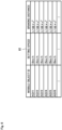
- FIG. 6 shows information indicating an example of the data structure of the mobile object setting information.
- mobile object setting information 61 includes mobile object identification information "mobile object ID” for identifying the mobile objects 20, setting speed information “setting speed” indicating moving speeds set for the respective mobile objects 20, and braking distance information "braking distance” indicating the braking distances of the mobile objects 20, which are associated with each other.
- the speed of each mobile object 20 suitably set in advance, the maximum speed of the mobile object 20, the maximum speed in the specifications of the mobile object 20, the current speed, or the like may be used as the setting speed information. Also, from the viewpoint of the energetic efficiency, safety at the time of collision, and the like, the maximum allowable speed may also be used as the setting speed information. Furthermore, the maximum acceleration rate or the like of the mobile object 20 may also be used.
- a braking distance differs according to a moving speed, and thus a braking distance that differs according to a setting speed may be set as the braking distance information.
- the braking distance information may have a configuration in which, for example, there are a plurality of stages in the setting speed, and a setting speed for each stage and a braking distance corresponding thereto are associated with each other.
- the braking distance information may also be expressed as a percentage of a setting speed.
- the braking distance information may be expressed in 10 stages, namely 1 to 10 [%], 11 to 20 [%], ..., and 91 to 100 [%] of the setting speed, for example. Furthermore, the braking distance information may also be expressed as a function of the setting speed. As shown in FIG. 6 , a value obtained by multiplying the square of a setting speed v by a coefficient (1/100 ⁇ V 2 ) may be used, for example. In FIG. 6 , "km/h" represents "kilometer per hour".
- the mobile object setting information may also be information that includes information indicating the type of each mobile object 20, setting speed information, and the braking distance information, which are associated with each other.
- a mobile object 20 is an automated guided vehicle
- the braking distance is affected by the brake performance thereof, friction with a floor surface, the loading capacity thereof, and the like, and thus the mobile object setting information may be generated through experiments, simulation, or the like, in consideration of the influence from these.
- the communication delay information is information regarding communication delay times of the mobile objects 20.
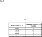
- FIG. 7 shows information indicating an example of the data structure of the communication delay information.
- communication delay information 71 includes identification information "mobile object ID” for identifying the mobile objects 20, communication delay time information "communication delay time [s] for indicating communication delay times (transmission delay times)", which are associated with each other.
- “s" represents "second”.
- the communication delay time information is information indicating a delay time in communication between the mobile object control apparatus 10 and each mobile object 20.
- the communication delay time information indicates a period of time (T1-T0) that has elapsed from a point in time T0 at which the mobile object 20 obtained the most recent mobile object position information to a point in time T1 at which the mobile object control apparatus 10 obtained the mobile object position information.
- the communication delay time information may be information for collectively managing several mobile objects 20 based on the communication processing capability of each mobile object 20, a communication protocol to be used, an area in which the mobile object 20 is present, and the like.
- the mobile object control apparatus 10 can accurately detect the position of the mobile object 20.
- a communication delay time is shorter than or equal to the threshold Th0 set in advance (the communication quality has decreased)
- the mobile object control apparatus 10 cannot accurately detect the position of the mobile object 20.
- the mobile object control apparatus 10 receives mobile object position information from the mobile object 20 with a communication delay time of 10 [seconds].
- the mobile object 20 is ahead of the position (coordinates) indicated by the position information by 10 [m], and thus, when the communication quality is decreased, the position of the mobile object 20 deviates largely. Therefore, the likelihood of the mobile objects 20 colliding with each other increases.
- the area information is information that is used for extracting a mobile object 20 that is other than the target mobile object 20 and is present near the target mobile object 20 at the present point in time.
- the area information is information indicating a range set in advance, is created by the user in advance, and is stored in the storage unit.
- a range that is set within a certain distance centered on the position (coordinates) of the target mobile object 20, a range that is set to include the position (coordinates) of the target mobile object 20, or a floor of a factory/logistic facility, etc., may be set as the "range", for example.
- the in-area mobile object information is information regarding position information of a mobile object 20 that is present in an area set based on the area information.
- FIG. 8 shows information indicating an example of the data structure of the in-area mobile object information.
- in-area mobile object information 81 area identification information "area ID” for identifying an area corresponding to the target mobile object 20 (the mobile object A), mobile object identification information “mobile object ID” for identifying a mobile object 20 in the area, obtaining time-and-date information “obtaining time and date” indicating time and date when position information of the mobile object 20 in the area was obtained, information “coordinate” indicating position information of the mobile object 20 in the area, and route identification information "route ID” for identifying a route corresponding to the mobile object 20 are associated with each other.
- route identification information is not necessary.
- the reason for providing the route identification information is to make it easy to distinguish which direction to proceed when a mobile object reaches an intersection at which a plurality of movement routes intersect.
- the in-area mobile object information may be generated for a mobile object 20 using the area information as described above, or may also be generated in an area set in advance, in a factory/facility, for example.
- a configuration may also be adopted in which, for example, in generation of in-area mobile object information for a set area, when a mobile object 20 enters the set area, a sensor apparatus installed in the area detects the mobile object 20, generates in-area mobile object information, and transmits the generated in-area mobile object information to the mobile object control apparatus 10.
- a mobile object 20 may reads and recognize information regarding the area from a tag installed at an entrance of the area, generate in-area mobile object information, and transmit the generated in-area mobile object information to the mobile object control apparatus 10.
- the tag may include a QR (Quick Response) code (registered trademark), or the like.
- a mobile object 20 may request the mobile object control apparatus 10 to transmit in-area mobile object information to the mobile object 20. Such a request may be made at a timing when the mobile object 20 enters an area that includes an intersection at which a collision can occur, a timing when a specific tag is read, or a timing when a certain task was completed, or may be made periodically.
- the temperature information is information indicating the surrounding temperature of the drive motor 26 provided in each mobile object 20.
- the remaining battery level information is information indicating the residual amount of the battery 27 provided in the mobile object 20.
- the carrying capacity information is information indicating the carrying capacity of the mobile object 20.
- the mobile object control apparatus will be described.
- the communication unit 13 communicates with the communication unit 21 of each mobile object 20. Specifically, the communication unit 13 transmits instruction information for controlling the mobile object 20, and the like to the mobile object 20. In addition, the communication unit 13 receives, from the mobile object 20, mobile object position information, temperature information, remaining battery level information, carrying capacity information, and the like.
- the instruction unit 14 generates instruction information to be used for moving the mobile object 20 to a target location.
- the instruction information includes information for accelerating/decelerating the mobile object 20, for example.
- the estimation unit 11 estimates the mobile object B that is highly likely to collide with the target mobile object A at an intersection. That is to say, the estimation unit 11 estimates times at which the mobile object A and the mobile object B will arrive at the intersection, and estimates whether or not the mobile object A and the mobile object B will collide at the intersection.
- the calculation unit 12 first estimates whether or not the mobile object A can pass through the intersection before the time at which the mobile object B will arrive at the intersection. Next, if it is estimated that the mobile object A cannot pass through the intersection before the time, the calculation unit 12 calculates speeds of the mobile objects A and B (the speed set 1 or 2) in accordance with a collision avoidance condition in order to avoid a collision with the mobile object B.
- the selection unit 19 selects one of the speed sets 1 and 2 based on one of or both the surrounding temperatures of the drive motors of the mobile object A and the mobile object B and the carrying capacities of the mobile object A and the mobile object B.
- estimation unit 11 the calculation unit 12, the selection unit 19, and the instruction unit 14 will be described later in detail.
- a mobile object will be described.
- the communication unit 21 communicates with the communication unit 13 of the mobile object control apparatus 10. Specifically, the communication unit 21 transmits the mobile object position information, the temperature information, the remaining battery level information, the carrying capacity information, and the like to the mobile object control apparatus 10. In addition, the communication unit 21 receives, from the mobile object control apparatus 10, instruction information to be used for performing movement control of the mobile object 20, and the like.
- the sensor unit 22 is a sensor that detects the state of the mobile object 20, a target object (for example, a tray and a shelf), a sign for assisting movement of the mobile object 20, and an obstacle and the like on an actual route, for example.
- the sensor unit 22 includes one or more of apparatuses such as a radar, an ultrasonic wave sensor, an image capturing apparatus, gyroscope, an encoder, and GPS (Global Positioning System).
- the position estimation unit 23 estimates the position of the mobile object 20 itself. Specifically, the position estimation unit 23 obtains measurement information indicating a measurement result of the sensor unit 22, estimates the position of the mobile object 20 itself based on the obtained measurement information, and generates mobile object position information.
- the movement control unit 24 controls the movement unit 25 that is provided in the mobile object 20 and is used for moving the mobile object 20. Specifically, the movement control unit 24 controls the movement unit 25 using the above information and the like, and moves the mobile object 20 to a target location. The movement control unit 24 controls a mechanism of the mobile object 20.
- the movement unit 25 is a device for moving the mobile object 20. Specifically, if the mobile object 20 is an automated guided vehicle, an electric automobile, or the like, the movement unit 25 is a means that is used for moving a vehicle, such as the drive motor 26, wheels (or crawler), the battery 27, and the like.
- the number of revolutions of the drive motor 26 is controlled by the movement control unit 24 in accordance with an operation of the mobile object 20 (for example, start, moving speed, or stop).
- the drive motor 26 is supplied with power from the battery 27.
- the battery 27 is a secondary battery such as a lithium ion battery, a nickel/hydrogen battery, a nickel/cadmium battery, or a lead storage battery. Note that a primary battery may be used as the battery 27.
- the temperature sensor 28 measures the surrounding temperature of the drive motor 26.
- the estimation unit will be described in detail.
- the collision estimation unit 15 estimates the mobile object B that is highly likely to collide with the target mobile object A at an intersection.
- the collision estimation unit 15 first obtains mobile object position information from mobile objects 20. Next, the collision estimation unit 15 extracts a mobile object 20 that is present in an area corresponding to the target mobile object 20, using the mobile object position information of the target mobile object 20 and the area information. The collision estimation unit 15 then generates in-area mobile object information related to the extracted mobile object 20, and stores the in-area mobile object information in the storage unit.
- the collision estimation unit 15 extracts mobile objects 20 that cannot be detected by the sensor unit 22 of the target mobile object A (mobile objects 20 that are hidden), from the mobile object 20 that is present in the area.
- the collision estimation unit 15 refers to the route information, extracts a mobile object 20 that has not arrived at the same intersection the target mobile object A has not arrived at, from among the mobile objects 20 that could not be detected by the sensor unit 22 of the target mobile object A, and sets the extracted mobile object 20 as a collision estimation target.
- the collision estimation unit 15 refers to the communication delay information, and obtains communication delay time information corresponding to the mobile object 20 set as a collision estimation target.
- the collision estimation unit 15 determines that that communication quality has decreased, and estimates that the selected mobile object 20 is the mobile object B that is highly likely to collide with the target mobile object A at the intersection.
- the average value, the median, the worst value, variations, or the like of transmission delay times at a predetermined time may be used as communication delay time information.
- the threshold Th0 may be obtained through experiments, simulation, or the like.
- a decrease in the communication quality may be a case where a region of a position at which the mobile object B can be present (for example, a region that is occupied by the mobile object B when it is assumed that the mobile object B moves in all possible directions at the maximum speed from a position thereof that was lastly obtained, during a period (present time - a time at which the position was obtained lastly + transmission delay time) ) has spread to a certain size (the length, the radium, the area, or the like of the region) or larger.
- a region of a position at which the mobile object B can be present for example, a region that is occupied by the mobile object B when it is assumed that the mobile object B moves in all possible directions at the maximum speed from a position thereof that was lastly obtained, during a period (present time - a time at which the position was obtained lastly + transmission delay time)
- a certain size the length, the radium, the area, or the like of the region
- a collision is avoided using a conventional collision avoidance technique.
- the conventional collision avoidance technique include priority control that is realized on FIFO (First In First Out) basis at the intersection.
- the arrival time estimation unit 16 refers to the mobile object setting information, and estimates times at which the target mobile object A and the mobile object B that is highly likely to collide with the target mobile object A will arrive at the intersection.
- the arrival time estimation unit 16 estimates a time at which the target mobile object A will arrive at the intersection, using the route information indicating a route corresponding to the target mobile object A, the position information indicating the position of the target mobile object A, the intersection position information indicating the position of an intersection that is present on the route, and the speed information indicating the speed of the target mobile object A.
- the arrival time estimation unit 16 estimates a time at which the mobile object B will arrive at the intersection, based on the route information indicating a route corresponding to the mobile object B that is highly likely to collide with the target mobile object A, the position information indicating the position of the mobile object B, the intersection position information indicating the position of an intersection that is present on the route, and the setting speed information indicating the setting speed of the mobile object B.
- the calculation unit will be described in detail.
- the passage estimation unit 17 estimates whether or not the target mobile object 20 can pass through the intersection before the time at which the mobile object 20 that is highly likely to collide with the target mobile object 20 will arrive at the intersection.
- the collision avoidance speed calculation unit 18 calculates a speed Va of the mobile object A and a speed Vb of the mobile object B (the speed set 1) that satisfy a collision avoidance condition expressed by Formula 1.
- a description will be given with reference to FIG. 9.
- the speed set 1 includes the speed Va for decreasing the current speed of the mobile object A and the current speed Vb of the mobile object B.
- the collision avoidance speed calculation unit 18 calculates the speed Va of the mobile object A and the speed Vb of the mobile object B (the speed set 2) that satisfy a collision avoidance condition expressed by Formula 2.
- the safety may be further increased by multiplying the right side of the collision avoidance condition of each of Formula 1 and Formula 2 by a safety factor ⁇ ( ⁇ 1).
- Formula 3 expresses a collision avoidance condition obtained by multiplying the right side of Formula 1 by the safety factor ⁇ .
- Formula 4 expresses a collision avoidance condition obtained by multiplying the right side of Formula 2 by the safety factor ⁇ . Dab > ⁇ Ta ⁇ Va + Dsa + Tb ⁇ Vb ⁇ : safety factor Dab > ⁇ Ta ⁇ Va + Tb ⁇ Vb + Dsb
- the selection unit will be described in detail.
- the selection unit 19 selects a speed set that prioritizes the lifespan, based on the magnitude relationship between the surrounding temperatures of the drive motors of the mobile object A and the mobile object B. In addition, if the surrounding temperatures of drive motors of the mobile object A and the mobile object B are lower than the threshold Th1 (are not higher than or equal to the threshold Th1), the selection unit 19 selects a speed set that prioritizes the carrying efficiency, based on the magnitude relationship between the carrying capacities of the mobile object A and the mobile object B.
- the selection unit 19 first obtains temperature information of the mobile obj ect A and temperature information of the mobile obj ect B. Next, the selection unit 19 determines whether or not a surrounding temperature Ha of the drive motor of the mobile object A or a surrounding temperature Hb of the drive motor of the mobile object B is higher than or equal to the threshold Th1 for temperature determination.
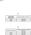
- the selection unit 19 refers to speed set selection information 91 shown in FIG. 10 , for example, and obtains a speed set that prioritizes the lifespan.
- FIG. 10 is a diagram showing an example of the data structure of the speed set selection information.
- the threshold Th1 is a temperature at which the lubricant of the drive motor 26 deteriorates, for example, and may be obtained through experiments, simulation, or the like.
- the speed set 2 is selected if the magnitude relationship between the surrounding temperatures is Ha>Hb, in order to decrease the speed of the mobile object B in which the temperature of the drive motor 26 is low. This prevents the mobile object A from being decelerated, and thus the number of revolutions of the drive motor 26 does not decrease, and the torque does not increase, whereby a current can be suppressed. Therefore, it is possible to suppress an increase in the temperature of the drive motor 26 of the mobile object A.
- the speed set 1 is selected if the magnitude relationship between the surrounding temperatures is Ha ⁇ Hb, in order to decrease the speed of the mobile obj ect A in which the temperature of the drive motor 26 is low. This prevents the mobile object B from being decelerated, and thus the number of revolutions of the drive motor 26 does not decrease, and the torque does not increase, whereby a current can be suppressed. Therefore, it is possible to suppress an increase in the temperature of the drive motor 26 of the mobile object B.
- a configuration may be adopted in which the number of times each mobile object 20 has reached the speed of the threshold Th1 set in advance or lower is stored, and the speed of the mobile object 20 for which the number of times is low decreased. This can suppress an increase in the temperature of a mobile object 20 that has reached the threshold Th1 or lower a larger number of times (that has a higher risk of temperature increase), and it is possible to suppress variation in lifespan of a plurality of automated guided vehicles.
- the selection unit 19 refers to speed set selection information 92 shown in FIG. 9 , for example, and obtains a speed set that prioritizes the carrying efficiency.
- the speed set 2 is selected if the magnitude relationship between the carrying capacities is Ca>Cb, in order to decrease the speed of the mobile object B that has a low carrying capacity. This prevents the mobile object A from being decelerated, and thus it is possible to improve the carrying efficiency of the mobile object A that has a high carrying capacity.
- the speed set 1 is selected if the magnitude relationship between the carrying capacities is Ca ⁇ Cb, in order to decrease the speed of the mobile object A that has a low carrying capacity. This prevents the mobile object B from being decelerated, and thus it is possible to improve the carrying efficiency of the mobile object B that has a high carrying capacity.
- a speed set that prioritizes the lifespan or a speed set that prioritizes the carrying efficiency is selected in accordance with the surrounding temperature Ha or Hb.
- the surrounding temperature Ha or Hb is higher than or equal to the threshold Th1
- only a speed set that prioritizes the lifespan may be selected.
- the surrounding temperatures Ha and Hb are lower than the threshold Th1 (are not higher than or equal to the threshold Th1), only a speed set that prioritizes the carrying efficiency may be selected.
- the instruction unit 14 will be described in detail.
- the instruction unit 14 generates instruction information for setting the moving speeds of the mobile objects A and B using the speed set 1 or 2 selected by the selection unit 19. Next, the instruction unit 14 transmits the instruction information to the mobile objects A and B.
- the mobile objects A and B change the moving speeds thereof based on the moving speeds included in the instruction information.
- FIG. 11 is a diagram for describing an exemplary operation of the mobile object control apparatus according to the first example embodiment.
- FIGS. 1 to 10 will be referred to as appropriate.
- a mobile object control method is executed as a result of operating the mobile object control apparatus.
- a description of the mobile object control method according to the first example embodiment is replaced with the following description of operations of the mobile object control apparatus.
- the estimation unit 11 estimates a mobile object 20 (the mobile object B) that is highly likely to collide with the target mobile object 20 (the mobile object A) at an intersection (step A1).
- step A1 the collision estimation unit 15 of the estimation unit 11 first obtains mobile object position information from the mobile objects 20.
- step A1 the collision estimation unit 15 extracts mobile objects 20 that are present in an area corresponding to the target mobile object A using the mobile object position information of the target mobile object A and the area information.
- the collision estimation unit 15 then generates in-area mobile object information related to the extracted mobile objects 20, such as that shown in FIG. 8 , and stores the generated in-area mobile object information in the storage unit.
- the collision estimation unit 15 further extracts mobile objects 20 that cannot be detected by the sensor unit 22 of the target mobile object 20 (mobile objects 20 that are hidden), from the mobile objects 20 that are present in the area.
- the collision estimation unit 15 further refers to the route information, extracts a mobile object 20 that has not arrived at the same intersection that the target mobile object 20 has not arrived at, from the mobile objects 20 that could not be detected by the sensor unit 22 of the target mobile object A, and selects the extracted mobile object 20 as a collision estimation target.
- the collision estimation unit 15 refers to the communication delay information, and obtains communication delay time information corresponding to the mobile object 20 selected as a collision estimation target.
- step A1 if the transmission delay time information is higher than or equal to the threshold Th0 set in advance, the collision estimation unit 15 determines that the communication quality has decreased, and estimates that the selected mobile object 20 is the mobile object B that is highly likely to collide with the target mobile object A at the intersection.
- step A2 when there is the mobile object B that is highly likely to collide with the target mobile object A (step A2: Yes), the estimation unit 11 estimates times at which the mobile object A and the mobile object B will arrive at the intersection (step A3). In addition, if there is no mobile object B that is highly likely to collide with the target mobile object A (step A2: No), the estimation unit 11 transitions the procedure to step A1.
- the arrival time estimation unit 16 of the estimation unit 11 estimates a time at which the target mobile object A will arrive at the intersection, based on the route information indicating a route corresponding to the target mobile object A, the position information indicating the position of the target mobile object A, the intersection position information indicating the position of an intersection that is present on the route, and the speed information indicating the speed of the target mobile object A.
- the arrival time estimation unit 16 estimates a time at which the mobile object B will arrive at the intersection, based on the route information indicating a route corresponding to the mobile object B that is highly likely to collide with the target mobile object A, the position information indicating the position of the mobile object B, the intersection position information indicating the position of an intersection that is present on the route, and the setting speed information indicating the setting speed of the mobile object B.
- the calculation unit 12 estimates whether or not the mobile object A can pass through the intersection before the time at which the mobile object B will arrive at the intersection (step A4).
- step A4 the passage estimation unit 17 estimates whether or not the target mobile obj ect A can pass through the intersection before the time at which the mobile obj ect A that is highly likely to collide with the target mobile object A will arrive at the intersection.
- step A5 if it is estimated that the mobile obj ect A cannot pass through the intersection before the time (step A5: No), the calculation unit 12 calculates the speed of the mobile object A in accordance with a collision avoidance condition in order to avoid a collision with the mobile object B (step A6). In addition, if it is estimated that the mobile object A can pass through the intersection (step A5: Yes), the calculation unit 12 transitions the procedure to step A1.
- step A6 if it is estimated that the target mobile object 20 cannot pass through the intersection before the time, the collision avoidance speed calculation unit 18 calculates a speed Ta of the mobile object A and a speed Tb of the mobile object B (the speed set 1) that satisfy a collision avoidance condition expressed by Formula 1.
- step A6 if it is estimated that the target mobile object 20 cannot pass through the intersection before the time, the collision avoidance speed calculation unit 18 calculates the speed Ta of the mobile object A and the speed Tb of the mobile object B (the speed set 2) that satisfy a collision avoidance condition expressed by Formula 2.
- the selection unit 19 first obtains the temperature information of the mobile object A and the temperature information of the mobile object B (step A7). Next, the selection unit 19 determines whether or not the surrounding temperature Ha of the drive motor of the mobile object A or the surrounding temperature Hb of the drive motor of the mobile object B is higher than or equal to the threshold Th1 for temperature determination (step A8).
- the selection unit 19 selects a speed set that prioritizes the lifespan, based on the magnitude relationship between the surrounding temperatures of the drive motors of the mobile object A and the mobile object B (step A9).
- the selection unit 19 selects a speed set that prioritizes the carrying efficiency, based on the magnitude relationship between the carrying capacities of the mobile object A and the mobile object B (step A10).
- the speed set that prioritizes the lifespan or the speed set that prioritizes the carrying efficiency is selected based on the surrounding temperature Ha or Hb. However, if the surrounding temperature Ha or Hb is higher than or equal to the threshold Th1, only the speed set that prioritizes the lifespan may be selected. Alternatively, if the surrounding temperatures Ha and Hb are lower than the threshold Th1 (are not higher than or equal to the threshold Th1), only the speed set that prioritizes the carrying efficiency may be selected.
- the instruction unit 14 generates instruction information for setting moving speeds of the mobile objects A and B using the speed set 1 or 2 selected by the selection unit 19 (step A11).
- the instruction unit 14 transmits the instruction information to the mobile objects A and B (step A12).
- the mobile objects A and B change the moving speeds thereof based on the moving speeds included in the instruction information.
- processing of steps A1 to A12 is repeatedly performed (when processing of step 12 ends, the processing starts from step A1 again).
- the speed of a mobile object is changed to a speed that prioritizes the lifespan based on the surrounding temperature of the drive motor of the mobile object, and thus the lifespan of the mobile object can be extended.
- the speed of a mobile object is changed to a speed that prioritizes the carrying efficiency based on the carrying capacity of the mobile object, and thus it is possible to suppress a decrease in the carrying efficiency of the mobile obj ect.
- the speed of a mobile object can be changed to a speed that prioritizes the lifespan or a speed that prioritizes the carrying efficiency in consideration of communication delay time of the mobile object, and thus it is possible to avoid a collision between mobile objects.
- a program according to the first example embodiment of the invention may be a program for causing a computer to execute steps A1 to A12 shown in FIG. 11 .
- the processor of the computer functions as the estimation unit 11 (the collision estimation unit 15, the arrival time estimation unit 16), the calculation unit 12 (the passage estimation unit 17, the collision avoidance speed calculation unit 18), the selection unit 19, the communication unit 13, and the instruction unit 14, and performs processing.
- the program according to the first example embodiment may also be executed by a computer system constituted by a plurality of computers.
- each of the computers may function as one of the estimation unit 11 (the collision estimation unit 15, the arrival time estimation unit 16), the calculation unit 12 (the passage estimation unit 17, the collision avoidance speed calculation unit 18), the selection unit 19, the communication unit 13, and the instruction unit 14.
- the configuration of the mobile object control apparatus 10 according to the second example embodiment will be described.
- a function for selecting a speed set using surrounding temperatures, carrying capacities, and remaining battery levels is added to the selection unit 19 according to the first example embodiment.
- the selection unit 19 selects a speed set based on the magnitude relationship between the surrounding temperatures of the drive motors 26 of the mobile object A and the mobile object B.
- the selection unit 19 selects a speed set based on the magnitude relationship between the carrying capacities of the mobile object A and the mobile object B.
- the selection unit 19 selects a speed set based on the magnitude relationship between the remaining battery levels of the mobile object A and the mobile object B.
- the threshold Th2 may be obtained through experiments, simulation, or the like.
- the second example embodiment will be described using the system 100a in FIG. 2 .
- the estimation unit 11 of the mobile object control apparatus 10 (the collision estimation unit 15, the arrival time estimation unit 16), the calculation unit 12 (the passage estimation unit 17, the collision avoidance speed calculation unit 18), the communication unit 13, and the instruction unit 14 have already been described, and thus a description thereof is omitted.
- the communication unit 21, the sensor unit 22, the position estimation unit 23, the movement control unit 24, the movement unit 25 (the drive motor 26, the battery 27), and the temperature sensor 28 of the mobile object 20 have already been described, and thus a description thereof is omitted.
- the storage unit also has already been described, and thus a description thereof is omitted.
- the selection unit according to the second example embodiment will be described in detail.
- the selection unit 19 selects a speed set that prioritizes the lifespan based on the magnitude relationship between the surrounding temperatures of the drive motors 26 of the mobile object A and the mobile object B.
- the selection unit 19 first obtains temperature information and remaining battery level information of each of the mobile object A and the mobile object B.
- the selection unit 19 determines whether or not the surrounding temperature Ha of the drive motor of the mobile object A or the surrounding temperature Hb of the drive motor of the mobile object B is higher than or equal to the threshold Th1 for temperature determination.
- the selection unit 19 determines whether or not a remaining battery level Sa of the mobile object A or the remaining battery level Sb of the mobile object B is higher than or equal to the threshold Th2 for remaining battery level determination.
- the selection unit 19 refers to the speed set selection information 91 shown in FIG. 10 , for example, and obtains a speed set that prioritizes the lifespan.
- the selection unit 19 determines whether or not the remaining battery level Sa of the mobile object A or the remaining battery level Sb of the mobile object B is higher than or equal to the threshold Th2 for remaining battery level determination.
- the selection unit 19 refers to the speed set selection information 92 in FIG. 10 , for example, and obtains a speed set that prioritizes the carrying efficiency.
- the selection unit 19 refers to the speed set selection information 1101 shown in FIG. 12 , for example, and obtains a speed set that prioritizes the remaining battery level.
- FIG. 12 is a diagram showing an example of the data structure of the speed set selection information.
- the speed set 1 is selected if the magnitude relationship between the remaining battery levels is Sa>Sb, in order to decrease the speed of the mobile object A in which the remaining battery level is high. This prevents the mobile object B from being decelerated, and thus it is possible to suppress a drive current to the drive motor 26 of the mobile object B in which the remaining battery level is low, and thereby to suppress the consumption amount of the battery of the mobile object B.
- the speed set 2 is selected if the magnitude relationship between the remaining battery levels is Sa ⁇ Sb, in order to decrease the speed of the mobile object B in which the remaining battery level is high. This prevents the mobile object A from being decelerated, and thus it is possible to suppress a drive current to the drive motor 26 of the mobile object A in which the remaining battery level is low, and thereby to suppress the consumption amount of the battery of the mobile object A.
- FIG. 13 is a diagram for describing an exemplary operation of the mobile object control apparatus according to the second example embodiment.
- FIGS. 1 to 12 will be referred to as appropriate.
- a mobile object control method is executed as a result of operating the mobile object control apparatus.
- a description of the mobile object control method according to the second example embodiment is replaced with the following description of operations of the mobile object control apparatus.
- Steps A1 to A12 shown in FIG. 13 have already been described in the first example embodiment, and thus a description thereof is omitted. Thus, steps A7', A8', B1, B2, and B3 will be described.
- the selection unit 19 first obtains temperature information and remaining battery level information of each of the mobile object A and the mobile object B (step A7').
- the selection unit 19 determines whether or not the surrounding temperature Ha of the drive motor of the mobile object A or the surrounding temperature Hb of the drive motor of the mobile object B is higher than or equal to the threshold Th1 for temperature determination (step A8').
- the selection unit 19 determines whether or not the remaining battery level Sa of the mobile object A or the remaining battery level Sb of the mobile object B is higher than or equal to the threshold Th2 for remaining battery level determination (step B1).
- the selection unit 19 refers to the speed set selection information 91 shown in FIG. 10 , for example, and obtains a speed set that prioritizes the lifespan (step A9).
- the selection unit 19 determines whether or not the remaining battery level Sa of the mobile object A or the remaining battery level Sb of the mobile object B is higher than or equal to the threshold Th2 for remaining battery level determination (step B2).
- the selection unit 19 refers to the speed set selection information 92 shown in FIG. 10 , for example, and obtains the speed set that prioritizes the carrying efficiency (step A10).
- the selection unit 19 refers to the speed set selection information 1101 shown in FIG. 12 ), for example, and obtains a speed set that prioritizes the remaining battery level (step B3).
- the speeds of mobile objects are changed to speeds that prioritize the remaining battery level based on the remaining battery levels of the mobile objects, and thus the consumption amounts of the batteries can be suppressed.
- the speeds of mobile objects are changed to speeds that prioritize the lifespan based on the surrounding temperatures of the drive motors of mobile objects, and thus the lifespans of the mobile objects can be extended.
- the speeds of mobile objects are changed to speeds that prioritize the carrying efficiency based on the carrying capacities of the mobile objects, and thus it is possible to suppress a decrease in the carrying efficiencies of the mobile objects.
- the speeds of mobile objects can be changed to speeds that prioritize the lifespan or speeds that prioritize the carrying efficiency in consideration of communication delay times of the mobile objects, and thus it is possible to avoid a collision between the mobile objects.
- the program according to an embodiment 2 of the invention may be a program that causes a computer to execute steps A1 to A6, A7', A8', A9 to A12, B1 to B3 shown in FIG. 13 .
- the processor of the computer performs processing to function as the estimation unit 11 (the collision estimation unit 15, the arrival time estimation unit 16), the calculation unit 12 (the passage estimation unit 17, the collision avoidance speed calculation unit 18), the selection unit 19, the communication unit 13, and the instruction unit 14.
- each computer may function as any of the estimation unit 11 (the collision estimation unit 15, the arrival time estimation unit 16), the calculation unit 12 (the passage estimation unit 17, the collision avoidance speed calculation unit 18), the selection unit 19, the communication unit 13, and the instruction unit 14.
- a mobile object-based system 100b shown in FIG. 3 will be described.
- the difference between the system 100a and the system 100b is that the estimation unit 11, the calculation unit 12, the selection unit 19, and the instruction unit 14 are mounted in a main mobile object 20m.
- the configuration of a sub mobile object 20 has a similar configuration to that of the mobile object 20 shown in FIG. 2 .
- the sub mobile object 20 communicates with the main mobile object 20m, the speeds of the mobile object 20m and the mobile object 20 are changed based on one or all of surrounding temperatures of the drive motors, carrying capacities, and remaining battery levels of the mobile objects, and thus it is possible to achieve effects similar to the above-described effects of the first and second example embodiments.
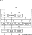
- FIG. 14 is a block diagram showing an example of a computer that realizes the mobile object control apparatus according to example embodiments 1 and 2 and a modified example 1 of the invention.
- a computer 110 includes a CPU (Central Processing Unit) 111, a main memory 112, a storage device 113, an input interface 114, a display controller 115, a data reader/writer 116, and a communications interface 117. These units are each connected so as to be capable of performing data communications with each other through a bus 121.
- the computer 110 may include a GPU (Graphics Processing Unit) or an FPGA (Field-Programmable Gate Array) in addition to the CPU 111 or in place of the CPU 111.
- the CPU 111 opens the program (code) according to this example embodiment, which has been stored in the storage device 113, in the main memory 112 and performs various operations by executing the program in a predetermined order.
- the main memory 112 is typically a volatile storage device such as a DRAM (Dynamic Random Access Memory).
- the program according to this example embodiment is provided in a state being stored in a computer-readable recording medium 120.
- the program according to this example embodiment may be distributed on the Internet, which is connected through the communications interface 117.
- the recording medium 120 is a non-volatile recording medium.
- the input interface 114 mediates data transmission between the CPU 111 and an input device 118, which may be a keyboard or mouse.
- the display controller 115 is connected to a display device 119, and controls display on the display device 119.
- the data reader/writer 116 mediates data transmission between the CPU 111 and the recording medium 120, and executes reading of a program from the recording medium 120 and writing of processing results in the computer 110 to the recording medium 120.
- the communications interface 117 mediates data transmission between the CPU 111 and other computers.
- CF Compact Flash (registered trademark)
- SD Secure Digital
- a magnetic recording medium such as a Flexible Disk
- an optical recording medium such as a CD-ROM (Compact Disk Read-Only Memory)
- CD-ROM Compact Disk Read-Only Memory
- the mobile object control apparatus 10 can also be realized by using hardware corresponding to each unit. Furthermore, a portion of the mobile object control apparatus 10 may be realized by a program, and the remaining portion realized by hardware.
- the invention it is possible to ensure a range in which an execution time of data processing can be estimated and reduce the cost for obtaining feature information of data processing.
- the invention is useful in a field in which an execution time of data processing needs to be estimated.
Landscapes
- Engineering & Computer Science (AREA)
- Radar, Positioning & Navigation (AREA)
- Remote Sensing (AREA)
- Physics & Mathematics (AREA)
- General Physics & Mathematics (AREA)
- Aviation & Aerospace Engineering (AREA)
- Automation & Control Theory (AREA)
- Control Of Position, Course, Altitude, Or Attitude Of Moving Bodies (AREA)
- Traffic Control Systems (AREA)
Abstract
Description
- The invention relates to a mobile object control apparatus and a mobile object control method for controlling mobile objects, and in particular relates to a computer-readable recording medium on which a program for realizing the apparatus and method is recorded.
- A conveyance system that uses an automated guided vehicle (AGV) improves the work efficiency, the production efficiency, and the like, and thus is introduced in various factories. In addition, automated guided vehicles are also introduced in various logistic facilities to realize work efficiency, prompt delivery, and the like.
- Moreover, in conveyance systems, it is necessary to avoid a collision between automated guided vehicles at an intersection at which routes that are set for the respective automated guided vehicles in advance intersect, in order to secure safety.
- In view of this, as a related technique,
Patent Document 1 discloses an information processing apparatus that causes an automated guided vehicle to make a detour and suppresses a decrease in the moving efficiency of the automated guided vehicle, in order to avoid a collision at an intersection. Moreover,Patent Document 2 discloses a system for safely moving a plurality of automated guided vehicles in an efficient manner without a deadlock being caused by interference between automated guided vehicles. -
- Patent Document 1:
Japanese Patent Laid-Open Publication No. 2018-129028 - Patent Document 2:
Japanese Patent Laid-Open Publication No. 2006-113687 - However, regarding automated guided vehicles in
Patent Documents - This is because, when the number of revolutions of the drive motor decreases (nearly a stopped state), the torque increases, and thus the current flowing to the drive motor increases. Therefore, when the current flowing to the drive motor increases, the amount of heat generation of the drive motor increases, and the lubricant of the drive motor deteriorates, thus shortening the lifespan of the drive motor.
- An example object of the invention is to provide a mobile object control apparatus, a mobile object control method, and a computer-readable recording medium for performing control so as to extend the lifespan of a mobile object capable of avoiding collisions.
- In order to achieve the example object described above, a mobile object control apparatus according to an example aspect of the invention includes:
- an estimation unit configured to estimate whether or not a target first mobile object and a second mobile object that is highly likely to collide with the first mobile object will collide with each other at an intersection;
- a calculation unit configured to calculate, if it is estimated that the first mobile object and the second mobile object will collide with each other at the intersection, a speed of the first mobile object and a speed of the second mobile object at which a collision at the intersection is avoidable, based on a collision avoidance condition set in advance; and
- a selection unit configured to select the speed of the first mobile object and the speed of the second mobile object calculated by the calculation unit, based on surrounding temperatures of drive motors of the first mobile object and the second mobile object, or carrying capacities of the first mobile object and the second mobile object, or both the surrounding temperatures and the carrying capacities.
- Also, in order to achieve the example object described above, a mobile object according to an example aspect of the invention includes:
- an estimation unit configured to estimate whether or not a target first mobile object and a second mobile object that is highly likely to collide with the first mobile object will collide with each other at an intersection;
- a calculation unit configured to calculate a speed of the first mobile object and a speed of the second mobile object at which a collision at the intersection is avoidable, based on a collision avoidance condition set in advance, if it is estimated that the first mobile object and the second mobile object will collide at the intersection;
- a selection unit configured to select the speed of the first mobile object and the speed of the second mobile object calculated by the calculation unit, based on surrounding temperatures of drive motors of the first mobile object and the second mobile object, or carrying capacities of the first mobile object and the second mobile object, or both the surrounding temperatures and the carrying capacities.
- Also, in order to achieve the example object described above, a system that performs moving control of a mobile object according to an example aspect of the invention includes:
- an estimation unit configured to estimate whether or not a target first mobile object and a second mobile object that is highly likely to collide with the first mobile object will collide with each other at an intersection;
- a calculation unit configured to calculate, if it is estimated that the first mobile object and the second mobile object will collide with each other at the intersection, a speed of the first mobile object and a speed of the second mobile object at which a collision at the intersection is avoidable, based on a collision avoidance condition set in advance; and
- a selection unit configured to select the speed of the first mobile object and the speed of the second mobile object calculated by the calculation unit, based on surrounding temperatures of drive motors of the first mobile object and the second mobile object, or carrying capacities of the first mobile object and the second mobile object, or both the surrounding temperatures and the carrying capacities.
- Also, in order to achieve the example object described above, a mobile object control method according to an example aspect of the invention includes:
- an estimation step of estimating whether or not a target first mobile object and a second mobile object that is highly likely to collide with the first mobile object will collide with each other at an intersection;
- a calculation step of calculating, if it is estimated that the first mobile object and the second mobile object will collide with each other at the intersection, a speed of the first mobile object and a speed of the second mobile object at which a collision at the intersection is avoidable, based on a collision avoidance condition set in advance; and
- a selection step of selecting the speed of the first mobile object and the speed of the second mobile object calculated by the calculation step, based on surrounding temperatures of drive motors of the first mobile object and the second mobile object, or carrying capacities of the first mobile object and the second mobile object, or both the surrounding temperatures and the carrying capacities.
- Furthermore, in order to achieve the example object described above, a computer-readable recording medium according to an example aspect of the invention includes a program recorded on the computer-readable recording medium, the program including instructions that cause the computer to carry out:
- an estimation step of estimating whether or not a target first mobile object and a second mobile object that is highly likely to collide with the first mobile object will collide with each other at an intersection;
- a calculation step of calculating, if it is estimated that the first mobile object and the second mobile object will collide with each other at the intersection, a speed of the first mobile object and a speed of the second mobile object at which a collision at the intersection is avoidable, based on a collision avoidance condition set in advance; and
- a selection step of selecting the speed of the first mobile object and the speed of the second mobile object calculated by the calculation step, based on surrounding temperatures of drive motors of the first mobile object and the second mobile object, or carrying capacities of the first mobile object and the second mobile object, or both the surrounding temperatures and the carrying capacities.
- As described above, according to the invention, it is possible to extend the lifespan of a mobile object capable of avoiding collisions.
-
-
FIG. 1 is a diagram for describing an example of the mobile object control apparatus according to the first example embodiment. -
FIG. 2 is a diagram for describing an example of a mobile object control apparatus-based system. -
FIG. 3 is a diagram for describing an example of a mobile object-based system. -
FIG. 4 shows information indicating an example of movement routes. -
FIG. 5 shows information indicating an example of the data structure of the route information. -
FIG. 6 shows information indicating an example of the data structure of the mobile object setting information. -
FIG. 7 shows information indicating an example of the data structure of the communication delay information. -
FIG. 8 shows information indicating an example of the data structure of the in-area mobile object information. -
FIG. 9 is a diagram for describing the collision avoidance condition. -
FIG. 10 is a diagram showing an example of the data structure of the speed set selection information. -
FIG. 11 is a diagram for describing an exemplary operation of the mobile object control apparatus according to the first example embodiment. -
FIG. 12 is a diagram showing an example of the data structure of the speed set selection information. -
FIG. 13 is a diagram for describing an exemplary operation of the mobile object control apparatus according to the second example embodiment. -
FIG. 14 is a diagram for showing an example of a computer that realizes the mobile object control apparatus. - The following describes a first example embodiment of the invention with reference to the drawings. Note that, in the drawings to be described below, the same reference numerals are given to constituent elements that have the same functions or corresponding functions, and a redundant description thereof may be omitted.
- First, the configuration of a mobile
object control apparatus 10 according to the first example embodiment will be described with reference toFIG. 1. FIG. 1 is a diagram for describing an example of the mobile object control apparatus according to the first example embodiment. - The mobile
object control apparatus 10 shown inFIG. 1 is an apparatus that can extend the lifespan of a mobile object capable of avoiding collision. In addition, as shown inFIG. 1 , the mobileobject control apparatus 10 includes anestimation unit 11, acalculation unit 12, and aselection unit 19. - Note that, hereinafter, for convenience purposes, a target mobile object 20 (first mobile object) may be referred to as a "mobile object A", and a
mobile object 20 that is highly likely to collide with the targetmobile object 20 may be referred to as a "mobile object B" (second mobile obj ect). - The
estimation unit 11 estimates whether or not the target mobile object A and the mobile object B that is highly likely to collide with the mobile object A will collide with each other at an intersection. - Specifically, the
estimation unit 11 calculates a time at which the mobile object A will arrive at an intersection (first arrival time) and a time at which the mobile object B that is highly likely to collide with the target mobile obj ect A will arrive at the intersection (second arrival time), using position information indicating a position, speed information indicating a speed, intersection position information indicating the position of an intersection, and communication delay time information indicating a communication delay time, for each of the target mobile obj ect A and the mobile object B, and estimates whether or not the mobile object A and the mobile object B will collide with each other at the intersection. - If it is estimated that the mobile object A and the mobile object B will collide at the intersection, the
calculation unit 12 calculates a speed of the mobile object A and a speed of the mobile object B at which a collision at the intersection is avoidable, based on a collision avoidance condition set in advance. - Specifically, if it is estimated that the mobile object A and the mobile object B will collide at the intersection, the
calculation unit 12 calculates a speed of the mobile object A and a speed of the mobile object B (a speed set 1) at which a collision at the intersection is avoidable, based on distance information indicating the path (for example, the distance) from the mobile object A to the mobile object B by way of the intersection, braking distance information indicating the braking distance of the mobile object A, and a collision avoidance condition expressed using the speed information and the communication delay times of the mobile object A and the mobile object B (first calculation means). - Moreover, if it is estimated that the mobile object A and the mobile object B will collide at the intersection, the
calculation unit 12 calculates a speed of the mobile object A and a speed of the mobile object B (a speed set 2) at which a collision at the intersection is avoidable, based on the distance information, braking distance information indicating the braking distance of the mobile object B, and a collision avoidance condition expressed using the speed information and the communication delay times of the mobile object A and the mobile object B (second calculation means). - Here, the path from the mobile object A to the mobile object B via the intersection is a length obtained by adding a path from the mobile object A to the intersection and a path from the mobile object B to the intersection.
- The
selection unit 19 selects the speed of the mobile object A and the speed of the mobile object B calculated by thecalculation unit 12, based on one of or both the surrounding temperatures of the drive motors of the mobile object A and the mobile object B and the carrying capacities of the mobile object A and the mobile object B. That is to say, theselection unit 19 selects the speed set 1 or thespeed set 2. - Specifically, if the surrounding temperature of the drive motor of the mobile object A or the mobile object B is higher than or equal to a threshold Th1 (first threshold) for determining a temperature set in advance, the
selection unit 19 selects speeds calculated by thecalculation unit 12, based on the magnitude relationship between the surrounding temperatures of the drive motors of the mobile object A and the mobile object B. - Moreover, if the surrounding temperatures of the drive motors of the mobile object A and the mobile object B are lower than the threshold Th1 (are not higher than or equal to the threshold Th1), the
selection unit 19 selects speeds calculated by thecalculation unit 12, based on the magnitude relationship between the carrying capacities of the mobile object A and the mobile object B. - In the first example embodiment, the speeds of mobile objects are changed to speeds that prioritize the lifespans thereof based on the surrounding temperatures of the drive motors of the mobile objects, and thus the lifespans of the mobile objects can be extended.
- Moreover, in the first example embodiment, the speeds of mobile objects are changed to speeds that prioritize the carrying efficiencies thereof based on the carrying capacities of the mobile objects, and thus it is possible to suppress a decrease in the carrying efficiencies of the mobile objects.
- Furthermore, in the first example embodiment, even if communication delay occurs due to a decrease in the communication quality, the speeds of the mobile objects can be changed to speeds that prioritize the lifespans thereof or speeds that prioritize the carrying efficiencies thereof in consideration of the communication delay times of the mobile objects, and thus it is possible to avoid a collision between the mobile objects.
-
FIG. 2 is a diagram for describing an example of a mobile object control apparatus-based system. Asystem 100a shown inFIG. 2 includes the mobileobject control apparatus 10 and a plurality ofmobile objects 20. Thesystem 100a also includes a storage unit (not illustrated inFIG. 2 ). - Note that the system may have a configuration in which a
mobile object 20 is the main element, such as asystem 100b shown inFIG. 3. FIG. 3 is a diagram for describing an example of a mobile object-based system. - Note that the configuration of the system is not limited to those of the
systems systems system 100a inFIG. 2 for convenience purposes. - The mobile
object control apparatus 10 performs, on each of themobile objects 20, control for moving themobile object 20 to a target location. - The mobile
object control apparatus 10 includes theestimation unit 11, thecalculation unit 12, theselection unit 19, acommunication unit 13, and aninstruction unit 14. Theestimation unit 11 includes acollision estimation unit 15 and an arrivaltime estimation unit 16. Thecalculation unit 12 includes apassage estimation unit 17 and a collision avoidancespeed calculation unit 18. - Note that the mobile
object control apparatus 10 is an information processing apparatus such as a server computer. - Each
mobile object 20 obtains, from the mobileobject control apparatus 10, instruction information to be used for performing moving control of themobile object 20, and moves to a target location based on the instruction information. - The
mobile object 20 includes acommunication unit 21, asensor unit 22, aposition estimation unit 23, amovement control unit 24, amovement unit 25, and atemperature sensor 28. Themovement unit 25 includes adrive motor 26 and abattery 27. - Note that the
mobile object 20 may be an automated guided vehicle, an automatic traveling vehicle, an automated flight vehicle, an automated navigation vessel, a robot, or the like. - The storage unit stores various types of information such as route information, mobile object position information, mobile object setting information, communication delay time information, area information, in-area mobile object information, temperature information, remaining battery level information, and carrying capacity information.
- Note that the storage unit may be provided inside or outside the mobile
object control apparatus 10. A plurality of storage units may also be provided. - The aforementioned information will be described.
- The route information is information related to routes on which the
mobile objects 20 move. In addition, the route information is created by the user in advance, and is stored in the storage unit.FIG. 4 shows information indicating an example of movement routes.FIG. 5 shows information indicating an example of the data structure of the route information. - The example in
FIG. 4 shows a coordinate system for expressing the positions (coordinates) of themobile objects 20 in a factory/logistic facility, etc., movement routes R1 to R13 (solid line arrows) on which themobile objects 20 move, and obstacles (hatched ranges). -
Route information 51 shown inFIG. 5 includes route identification information "route ID" for identifying each route, route start point information "start point" indicating the coordinates of the start point of the route, route end point information "end point" indicating the coordinates of the end point of the route, pass point information "pass point" indicating coordinates through which themobile object 20 passes when themobile object 20 travels from the start point to the end point (coordinates on which themobile object 20 changes directions), route shape information "shape" indicating the shapes of the movement route, and intersection information "intersection" indicating the position of an intersection on the movement route, which are associated with each other. - Note that information indicating a site from which luggage is carried in, a destination to which luggage is carried, stand-by locations of the
mobile objects 20, a charging location of themobile objects 20, and the like (which are not illustrated inFIG. 4 ) may be added to theroute information 51. - The mobile object position information is information regarding the positions of the mobile objects 20. In addition, the mobile object position information is generated by the
mobile objects 20, and is stored in the storage unit. - The mobile object position information is information that includes mobile object identification information for identifying each
mobile object 20, position information indicating the position of themobile object 20, and time-and-date information indicating time and date when the information indicating the position was obtained, which are associated with each other. In addition, speed information indicating the speeds of themobile objects 20 may be added to the mobile object position information. - The position information is information indicating coordinates, for example. Note that the position information may indicate the positions of the
mobile objects 20 using absolute coordinates, relative coordinates, vectors, patches, or the like. - As a method for obtaining the mobile object position information, the mobile
object control apparatus 10 may perform polling every certain period of time, and obtain the mobile object position information from the mobile objects 20. Alternatively, the mobileobject control apparatus 10 may also obtain mobile object position information that is transmitted by themobile objects 20 every certain period of time. Alternatively, a configuration may also be adopted in which tags or the like that include position information are installed on a wall, a floor, and the like at a predetermined interval (interval corresponding to coordinates), and every time amobile object 20 passes over a tag, mobile object position information is transmitted to the mobileobject control apparatus 10. - The mobile obj ect setting information is information regarding the positions of the mobile objects 20. In addition, the mobile object setting information is created by the user in advance, and is stored in the storage unit.
FIG. 6 shows information indicating an example of the data structure of the mobile object setting information. As shown inFIG. 6 , mobileobject setting information 61 includes mobile object identification information "mobile object ID" for identifying themobile objects 20, setting speed information "setting speed" indicating moving speeds set for the respectivemobile objects 20, and braking distance information "braking distance" indicating the braking distances of themobile objects 20, which are associated with each other. - The speed of each
mobile object 20 suitably set in advance, the maximum speed of themobile object 20, the maximum speed in the specifications of themobile object 20, the current speed, or the like may be used as the setting speed information. Also, from the viewpoint of the energetic efficiency, safety at the time of collision, and the like, the maximum allowable speed may also be used as the setting speed information. Furthermore, the maximum acceleration rate or the like of themobile object 20 may also be used. - A braking distance differs according to a moving speed, and thus a braking distance that differs according to a setting speed may be set as the braking distance information. The braking distance information may have a configuration in which, for example, there are a plurality of stages in the setting speed, and a setting speed for each stage and a braking distance corresponding thereto are associated with each other. In addition, the braking distance information may also be expressed as a percentage of a setting speed.
- The braking distance information may be expressed in 10 stages, namely 1 to 10 [%], 11 to 20 [%], ..., and 91 to 100 [%] of the setting speed, for example. Furthermore, the braking distance information may also be expressed as a function of the setting speed. As shown in
FIG. 6 , a value obtained by multiplying the square of a setting speed v by a coefficient (1/100×V2) may be used, for example. InFIG. 6 , "km/h" represents "kilometer per hour". - Note that the mobile object setting information may also be information that includes information indicating the type of each
mobile object 20, setting speed information, and the braking distance information, which are associated with each other. - Furthermore, if a
mobile object 20 is an automated guided vehicle, the braking distance is affected by the brake performance thereof, friction with a floor surface, the loading capacity thereof, and the like, and thus the mobile object setting information may be generated through experiments, simulation, or the like, in consideration of the influence from these. - The communication delay information is information regarding communication delay times of the mobile objects 20.
FIG. 7 shows information indicating an example of the data structure of the communication delay information. As shown inFIG. 7 ,communication delay information 71 includes identification information "mobile object ID" for identifying themobile objects 20, communication delay time information "communication delay time [s] for indicating communication delay times (transmission delay times)", which are associated with each other. InFIG. 7 , "s" represents "second". - The communication delay time information is information indicating a delay time in communication between the mobile
object control apparatus 10 and eachmobile object 20. Specifically, the communication delay time information indicates a period of time (T1-T0) that has elapsed from a point in time T0 at which themobile object 20 obtained the most recent mobile object position information to a point in time T1 at which the mobileobject control apparatus 10 obtained the mobile object position information. In addition, the communication delay time information may be information for collectively managing severalmobile objects 20 based on the communication processing capability of eachmobile object 20, a communication protocol to be used, an area in which themobile object 20 is present, and the like. - Here, if a communication delay time is shorter than a threshold Th0 set in advance (the communication quality has not been decreased), the mobile
object control apparatus 10 can accurately detect the position of themobile object 20. However, if a communication delay time is longer than or equal to the threshold Th0 set in advance (the communication quality has decreased), the mobileobject control apparatus 10 cannot accurately detect the position of themobile object 20. - Assume that, for example, a
mobile object 20 moves in one direction at 1 [m] per second, and the mobileobject control apparatus 10 receives mobile object position information from themobile object 20 with a communication delay time of 10 [seconds]. In that case, themobile object 20 is ahead of the position (coordinates) indicated by the position information by 10 [m], and thus, when the communication quality is decreased, the position of themobile object 20 deviates largely. Therefore, the likelihood of themobile objects 20 colliding with each other increases. - The area information is information that is used for extracting a
mobile object 20 that is other than the targetmobile object 20 and is present near the targetmobile object 20 at the present point in time. The area information is information indicating a range set in advance, is created by the user in advance, and is stored in the storage unit. - A range that is set within a certain distance centered on the position (coordinates) of the target
mobile object 20, a range that is set to include the position (coordinates) of the targetmobile object 20, or a floor of a factory/logistic facility, etc., may be set as the "range", for example. - The in-area mobile object information is information regarding position information of a
mobile object 20 that is present in an area set based on the area information.FIG. 8 shows information indicating an example of the data structure of the in-area mobile object information. - As shown in
FIG. 8 , in in-areamobile object information 81, area identification information "area ID" for identifying an area corresponding to the target mobile object 20 (the mobile object A), mobile object identification information "mobile object ID" for identifying amobile object 20 in the area, obtaining time-and-date information "obtaining time and date" indicating time and date when position information of themobile object 20 in the area was obtained, information "coordinate" indicating position information of themobile object 20 in the area, and route identification information "route ID" for identifying a route corresponding to themobile object 20 are associated with each other. - Note that the route identification information is not necessary. The reason for providing the route identification information is to make it easy to distinguish which direction to proceed when a mobile object reaches an intersection at which a plurality of movement routes intersect.
- The in-area mobile object information may be generated for a
mobile object 20 using the area information as described above, or may also be generated in an area set in advance, in a factory/facility, for example. - A configuration may also be adopted in which, for example, in generation of in-area mobile object information for a set area, when a
mobile object 20 enters the set area, a sensor apparatus installed in the area detects themobile object 20, generates in-area mobile object information, and transmits the generated in-area mobile object information to the mobileobject control apparatus 10. Alternatively, when entering the area, amobile object 20 may reads and recognize information regarding the area from a tag installed at an entrance of the area, generate in-area mobile object information, and transmit the generated in-area mobile object information to the mobileobject control apparatus 10. The tag may include a QR (Quick Response) code (registered trademark), or the like. - Moreover, a
mobile object 20 may request the mobileobject control apparatus 10 to transmit in-area mobile object information to themobile object 20. Such a request may be made at a timing when themobile object 20 enters an area that includes an intersection at which a collision can occur, a timing when a specific tag is read, or a timing when a certain task was completed, or may be made periodically. - The temperature information is information indicating the surrounding temperature of the
drive motor 26 provided in eachmobile object 20. - The remaining battery level information is information indicating the residual amount of the
battery 27 provided in themobile object 20. - The carrying capacity information is information indicating the carrying capacity of the
mobile object 20. The carrying capacity is expressed by the amount of luggage that can be loaded × speed ( = amount that can be carried per unit time × distance), for example. - The mobile object control apparatus will be described.
- The
communication unit 13 communicates with thecommunication unit 21 of eachmobile object 20. Specifically, thecommunication unit 13 transmits instruction information for controlling themobile object 20, and the like to themobile object 20. In addition, thecommunication unit 13 receives, from themobile object 20, mobile object position information, temperature information, remaining battery level information, carrying capacity information, and the like. - The
instruction unit 14 generates instruction information to be used for moving themobile object 20 to a target location. The instruction information includes information for accelerating/decelerating themobile object 20, for example. - The
estimation unit 11 estimates the mobile object B that is highly likely to collide with the target mobile object A at an intersection. That is to say, theestimation unit 11 estimates times at which the mobile object A and the mobile object B will arrive at the intersection, and estimates whether or not the mobile object A and the mobile object B will collide at the intersection. - The
calculation unit 12 first estimates whether or not the mobile object A can pass through the intersection before the time at which the mobile object B will arrive at the intersection. Next, if it is estimated that the mobile object A cannot pass through the intersection before the time, thecalculation unit 12 calculates speeds of the mobile objects A and B (the speed set 1 or 2) in accordance with a collision avoidance condition in order to avoid a collision with the mobile object B. - The collision avoidance condition is expressed using, for example, distance information indicating the distance between mobile objects, namely the mobile object A and the mobile object B ( = "the sum of the path between the mobile object A and the intersection and the path between the mobile object B and the intersection" ), the braking distance of the mobile object A or B, and setting speed information and communication delay times of the mobile objects A and B.
- The
selection unit 19 selects one of the speed sets 1 and 2 based on one of or both the surrounding temperatures of the drive motors of the mobile object A and the mobile object B and the carrying capacities of the mobile object A and the mobile object B. - Note that the
estimation unit 11, thecalculation unit 12, theselection unit 19, and theinstruction unit 14 will be described later in detail. - A mobile object will be described.
- The
communication unit 21 communicates with thecommunication unit 13 of the mobileobject control apparatus 10. Specifically, thecommunication unit 21 transmits the mobile object position information, the temperature information, the remaining battery level information, the carrying capacity information, and the like to the mobileobject control apparatus 10. In addition, thecommunication unit 21 receives, from the mobileobject control apparatus 10, instruction information to be used for performing movement control of themobile object 20, and the like. - The
sensor unit 22 is a sensor that detects the state of themobile object 20, a target object (for example, a tray and a shelf), a sign for assisting movement of themobile object 20, and an obstacle and the like on an actual route, for example. Specifically, thesensor unit 22 includes one or more of apparatuses such as a radar, an ultrasonic wave sensor, an image capturing apparatus, gyroscope, an encoder, and GPS (Global Positioning System). - The
position estimation unit 23 estimates the position of themobile object 20 itself. Specifically, theposition estimation unit 23 obtains measurement information indicating a measurement result of thesensor unit 22, estimates the position of themobile object 20 itself based on the obtained measurement information, and generates mobile object position information. - The
movement control unit 24 controls themovement unit 25 that is provided in themobile object 20 and is used for moving themobile object 20. Specifically, themovement control unit 24 controls themovement unit 25 using the above information and the like, and moves themobile object 20 to a target location. Themovement control unit 24 controls a mechanism of themobile object 20. - The
movement unit 25 is a device for moving themobile object 20. Specifically, if themobile object 20 is an automated guided vehicle, an electric automobile, or the like, themovement unit 25 is a means that is used for moving a vehicle, such as thedrive motor 26, wheels (or crawler), thebattery 27, and the like. - The number of revolutions of the
drive motor 26 is controlled by themovement control unit 24 in accordance with an operation of the mobile object 20 (for example, start, moving speed, or stop). Thedrive motor 26 is supplied with power from thebattery 27. - The
battery 27 is a secondary battery such as a lithium ion battery, a nickel/hydrogen battery, a nickel/cadmium battery, or a lead storage battery. Note that a primary battery may be used as thebattery 27. Thetemperature sensor 28 measures the surrounding temperature of thedrive motor 26. - The estimation unit will be described in detail.
- The
collision estimation unit 15 estimates the mobile object B that is highly likely to collide with the target mobile object A at an intersection. - Specifically, the
collision estimation unit 15 first obtains mobile object position information frommobile objects 20. Next, thecollision estimation unit 15 extracts amobile object 20 that is present in an area corresponding to the targetmobile object 20, using the mobile object position information of the targetmobile object 20 and the area information. Thecollision estimation unit 15 then generates in-area mobile object information related to the extractedmobile object 20, and stores the in-area mobile object information in the storage unit. - Next, the
collision estimation unit 15 extractsmobile objects 20 that cannot be detected by thesensor unit 22 of the target mobile object A (mobile objects 20 that are hidden), from themobile object 20 that is present in the area. - Next, the
collision estimation unit 15 refers to the route information, extracts amobile object 20 that has not arrived at the same intersection the target mobile object A has not arrived at, from among themobile objects 20 that could not be detected by thesensor unit 22 of the target mobile object A, and sets the extractedmobile object 20 as a collision estimation target. - Next, the
collision estimation unit 15 refers to the communication delay information, and obtains communication delay time information corresponding to themobile object 20 set as a collision estimation target. - Next, if the communication delay time information is higher than or equal to the threshold Th0 set in advance, the
collision estimation unit 15 determines that that communication quality has decreased, and estimates that the selectedmobile object 20 is the mobile object B that is highly likely to collide with the target mobile object A at the intersection. - The average value, the median, the worst value, variations, or the like of transmission delay times at a predetermined time may be used as communication delay time information. The threshold Th0 may be obtained through experiments, simulation, or the like.
- A decrease in the communication quality may be a case where a region of a position at which the mobile object B can be present (for example, a region that is occupied by the mobile object B when it is assumed that the mobile object B moves in all possible directions at the maximum speed from a position thereof that was lastly obtained, during a period (present time - a time at which the position was obtained lastly + transmission delay time) ) has spread to a certain size (the length, the radium, the area, or the like of the region) or larger.
- Note that, when the communication quality recovers, and a
mobile object 20 that is highly likely to collide with the targetmobile object 20 can be detected by thesensor unit 22 of the targetmobile object 20, a collision is avoided using a conventional collision avoidance technique. Examples of the conventional collision avoidance technique include priority control that is realized on FIFO (First In First Out) basis at the intersection. - When the mobile object B that is highly likely to collide with the target mobile object A is estimated, the arrival
time estimation unit 16 refers to the mobile object setting information, and estimates times at which the target mobile object A and the mobile object B that is highly likely to collide with the target mobile object A will arrive at the intersection. - Specifically, the arrival
time estimation unit 16 estimates a time at which the target mobile object A will arrive at the intersection, using the route information indicating a route corresponding to the target mobile object A, the position information indicating the position of the target mobile object A, the intersection position information indicating the position of an intersection that is present on the route, and the speed information indicating the speed of the target mobile object A. - Also, the arrival
time estimation unit 16 estimates a time at which the mobile object B will arrive at the intersection, based on the route information indicating a route corresponding to the mobile object B that is highly likely to collide with the target mobile object A, the position information indicating the position of the mobile object B, the intersection position information indicating the position of an intersection that is present on the route, and the setting speed information indicating the setting speed of the mobile object B. - The calculation unit will be described in detail.
- The
passage estimation unit 17 estimates whether or not the targetmobile object 20 can pass through the intersection before the time at which themobile object 20 that is highly likely to collide with the targetmobile object 20 will arrive at the intersection. - If it is estimated that the target
mobile object 20 cannot pass through the intersection before the time, the collision avoidancespeed calculation unit 18 calculates a speed Va of the mobile object A and a speed Vb of the mobile object B (the speed set 1) that satisfy a collision avoidance condition expressed byFormula 1. A description will be given with reference toFIG. 9. FIG. 9 is a diagram for describing the collision avoidance condition.

- Da: path from the mobile object A to the intersection
- Db: path from the mobile object B to the intersection
- Dab: path from the mobile object A to the mobile object B via the intersection
- Dsa: braking distance of the moving object A
- Ta: communication delay times of the moving object A
- Va: moving speeds of moving body A
- Tb: communication delay times of the moving object B
- Vb: moving speeds of moving body B
- Specifically, the speed set 1 includes the speed Va for decreasing the current speed of the mobile object A and the current speed Vb of the mobile object B.
- Moreover, if it is estimated that the target
mobile object 20 cannot pass through the intersection before the time, the collision avoidancespeed calculation unit 18 calculates the speed Va of the mobile object A and the speed Vb of the mobile object B (the speed set 2) that satisfy a collision avoidance condition expressed byFormula 2. Specifically, the speed set 2 includes the speed Vb for decreasing the current speed of the mobile object B and the current speed Va of the mobile object A.

- Moreover, in calculation of
Formula 1 andFormula 2 above, the safety may be further increased by multiplying the right side of the collision avoidance condition of each ofFormula 1 andFormula 2 by a safety factor α (<1). Formula 3 expresses a collision avoidance condition obtained by multiplying the right side ofFormula 1 by the safety factor α. In addition, Formula 4 expresses a collision avoidance condition obtained by multiplying the right side ofFormula 2 by the safety factor α.


- The selection unit will be described in detail.
- If the surrounding temperature of the drive motor of the mobile object A or the mobile object B is higher than or equal to the threshold Th1, the
selection unit 19 selects a speed set that prioritizes the lifespan, based on the magnitude relationship between the surrounding temperatures of the drive motors of the mobile object A and the mobile object B. In addition, if the surrounding temperatures of drive motors of the mobile object A and the mobile object B are lower than the threshold Th1 (are not higher than or equal to the threshold Th1), theselection unit 19 selects a speed set that prioritizes the carrying efficiency, based on the magnitude relationship between the carrying capacities of the mobile object A and the mobile object B. - Specifically, the
selection unit 19 first obtains temperature information of the mobile obj ect A and temperature information of the mobile obj ect B. Next, theselection unit 19 determines whether or not a surrounding temperature Ha of the drive motor of the mobile object A or a surrounding temperature Hb of the drive motor of the mobile object B is higher than or equal to the threshold Th1 for temperature determination. - Next, if the surrounding temperature Ha or Hb is higher than or equal to the threshold Th1, the
selection unit 19 refers to speed setselection information 91 shown inFIG. 10 , for example, and obtains a speed set that prioritizes the lifespan.FIG. 10 is a diagram showing an example of the data structure of the speed set selection information. - The threshold Th1 is a temperature at which the lubricant of the
drive motor 26 deteriorates, for example, and may be obtained through experiments, simulation, or the like. - When the speed
set selection information 91 inFIG. 10 is used, theselection unit 19 obtains the speed set 2 if the magnitude relationship between the surrounding temperatures is Ha>Hb, and obtains the speed set 1 if the magnitude relationship between the surrounding temperatures is Ha<Hb. Note that if the magnitude relationship between the surrounding temperatures is Ha = Hb, one of the speed sets 1 and 2 is obtained. - The speed set 2 is selected if the magnitude relationship between the surrounding temperatures is Ha>Hb, in order to decrease the speed of the mobile object B in which the temperature of the
drive motor 26 is low. This prevents the mobile object A from being decelerated, and thus the number of revolutions of thedrive motor 26 does not decrease, and the torque does not increase, whereby a current can be suppressed. Therefore, it is possible to suppress an increase in the temperature of thedrive motor 26 of the mobile object A. - Moreover, the speed set 1 is selected if the magnitude relationship between the surrounding temperatures is Ha<Hb, in order to decrease the speed of the mobile obj ect A in which the temperature of the
drive motor 26 is low. This prevents the mobile object B from being decelerated, and thus the number of revolutions of thedrive motor 26 does not decrease, and the torque does not increase, whereby a current can be suppressed. Therefore, it is possible to suppress an increase in the temperature of thedrive motor 26 of the mobile object B. - In this manner, by controlling mobile objects, it is possible to suppress variation in the lifespans of the plurality of
mobile objects 20 in thesystem 100a. - Furthermore, a configuration may be adopted in which the number of times each
mobile object 20 has reached the speed of the threshold Th1 set in advance or lower is stored, and the speed of themobile object 20 for which the number of times is low decreased. This can suppress an increase in the temperature of amobile object 20 that has reached the threshold Th1 or lower a larger number of times (that has a higher risk of temperature increase), and it is possible to suppress variation in lifespan of a plurality of automated guided vehicles. - Moreover, if the surrounding temperatures Ha and Hb are lower than the threshold Th1 (are not higher than or equal to the threshold Th1), the
selection unit 19 refers to speed setselection information 92 shown inFIG. 9 , for example, and obtains a speed set that prioritizes the carrying efficiency. - When the speed
set selection information 92 inFIG. 10 is used, theselection unit 19 obtains the speed set 2 if the magnitude relationship between the carrying capacities is Ca>Cb, and obtains the speed set 1 if the magnitude relationship between the carrying capacities is Ca<Cb. Note that, if the magnitude relationship between the carrying capacities is Ca = Cb, one of the speed sets 1 and 2 is obtained. - The speed set 2 is selected if the magnitude relationship between the carrying capacities is Ca>Cb, in order to decrease the speed of the mobile object B that has a low carrying capacity. This prevents the mobile object A from being decelerated, and thus it is possible to improve the carrying efficiency of the mobile object A that has a high carrying capacity.
- Also, the speed set 1 is selected if the magnitude relationship between the carrying capacities is Ca<Cb, in order to decrease the speed of the mobile object A that has a low carrying capacity. This prevents the mobile object B from being decelerated, and thus it is possible to improve the carrying efficiency of the mobile object B that has a high carrying capacity.
- Note that, in the above example, a speed set that prioritizes the lifespan or a speed set that prioritizes the carrying efficiency is selected in accordance with the surrounding temperature Ha or Hb. However, if the surrounding temperature Ha or Hb is higher than or equal to the threshold Th1, only a speed set that prioritizes the lifespan may be selected. Alternatively, if the surrounding temperatures Ha and Hb are lower than the threshold Th1 (are not higher than or equal to the threshold Th1), only a speed set that prioritizes the carrying efficiency may be selected.
- The
instruction unit 14 will be described in detail. - The
instruction unit 14 generates instruction information for setting the moving speeds of the mobile objects A and B using the speed set 1 or 2 selected by theselection unit 19. Next, theinstruction unit 14 transmits the instruction information to the mobile objects A and B. - When the instruction information is obtained, the mobile objects A and B change the moving speeds thereof based on the moving speeds included in the instruction information.
- Next, operations of the mobile object control apparatus according to the first example embodiment of the invention will be described with reference to
FIG. 11. FIG. 11 is a diagram for describing an exemplary operation of the mobile object control apparatus according to the first example embodiment. In the following description,FIGS. 1 to 10 will be referred to as appropriate. In addition, in the first example embodiment, a mobile object control method is executed as a result of operating the mobile object control apparatus. Thus, a description of the mobile object control method according to the first example embodiment is replaced with the following description of operations of the mobile object control apparatus. - As shown in
FIG. 11 , first, theestimation unit 11 estimates a mobile object 20 (the mobile object B) that is highly likely to collide with the target mobile object 20 (the mobile object A) at an intersection (step A1). - Specifically, in step A1, the
collision estimation unit 15 of theestimation unit 11 first obtains mobile object position information from the mobile objects 20. Next, in step A1, thecollision estimation unit 15 extractsmobile objects 20 that are present in an area corresponding to the target mobile object A using the mobile object position information of the target mobile object A and the area information. Thecollision estimation unit 15 then generates in-area mobile object information related to the extractedmobile objects 20, such as that shown inFIG. 8 , and stores the generated in-area mobile object information in the storage unit. - Next, in step A1, the
collision estimation unit 15 further extractsmobile objects 20 that cannot be detected by thesensor unit 22 of the target mobile object 20 (mobile objects 20 that are hidden), from themobile objects 20 that are present in the area. - Next, in step A1, the
collision estimation unit 15 further refers to the route information, extracts amobile object 20 that has not arrived at the same intersection that the targetmobile object 20 has not arrived at, from themobile objects 20 that could not be detected by thesensor unit 22 of the target mobile object A, and selects the extractedmobile object 20 as a collision estimation target. - Next, in step A1, the
collision estimation unit 15 refers to the communication delay information, and obtains communication delay time information corresponding to themobile object 20 selected as a collision estimation target. - Next, in step A1, if the transmission delay time information is higher than or equal to the threshold Th0 set in advance, the
collision estimation unit 15 determines that the communication quality has decreased, and estimates that the selectedmobile object 20 is the mobile object B that is highly likely to collide with the target mobile object A at the intersection. - Next, when there is the mobile object B that is highly likely to collide with the target mobile object A (step A2: Yes), the
estimation unit 11 estimates times at which the mobile object A and the mobile object B will arrive at the intersection (step A3). In addition, if there is no mobile object B that is highly likely to collide with the target mobile object A (step A2: No), theestimation unit 11 transitions the procedure to step A1. - Specifically, in step A3, the arrival
time estimation unit 16 of theestimation unit 11 estimates a time at which the target mobile object A will arrive at the intersection, based on the route information indicating a route corresponding to the target mobile object A, the position information indicating the position of the target mobile object A, the intersection position information indicating the position of an intersection that is present on the route, and the speed information indicating the speed of the target mobile object A. - Moreover, in step A3, the arrival
time estimation unit 16 estimates a time at which the mobile object B will arrive at the intersection, based on the route information indicating a route corresponding to the mobile object B that is highly likely to collide with the target mobile object A, the position information indicating the position of the mobile object B, the intersection position information indicating the position of an intersection that is present on the route, and the setting speed information indicating the setting speed of the mobile object B. - Next, the
calculation unit 12 estimates whether or not the mobile object A can pass through the intersection before the time at which the mobile object B will arrive at the intersection (step A4). - Specifically, in step A4, the
passage estimation unit 17 estimates whether or not the target mobile obj ect A can pass through the intersection before the time at which the mobile obj ect A that is highly likely to collide with the target mobile object A will arrive at the intersection. - Next, if it is estimated that the mobile obj ect A cannot pass through the intersection before the time (step A5: No), the
calculation unit 12 calculates the speed of the mobile object A in accordance with a collision avoidance condition in order to avoid a collision with the mobile object B (step A6). In addition, if it is estimated that the mobile object A can pass through the intersection (step A5: Yes), thecalculation unit 12 transitions the procedure to step A1. - Specifically, in step A6, if it is estimated that the target
mobile object 20 cannot pass through the intersection before the time, the collision avoidancespeed calculation unit 18 calculates a speed Ta of the mobile object A and a speed Tb of the mobile object B (the speed set 1) that satisfy a collision avoidance condition expressed byFormula 1. - Moreover, in step A6, if it is estimated that the target
mobile object 20 cannot pass through the intersection before the time, the collision avoidancespeed calculation unit 18 calculates the speed Ta of the mobile object A and the speed Tb of the mobile object B (the speed set 2) that satisfy a collision avoidance condition expressed byFormula 2. - Next, the
selection unit 19 first obtains the temperature information of the mobile object A and the temperature information of the mobile object B (step A7). Next, theselection unit 19 determines whether or not the surrounding temperature Ha of the drive motor of the mobile object A or the surrounding temperature Hb of the drive motor of the mobile object B is higher than or equal to the threshold Th1 for temperature determination (step A8). - Specifically, if the surrounding temperature Ha or Hb is higher than or equal to the threshold Th1 (step A8: Yes), the
selection unit 19 selects a speed set that prioritizes the lifespan, based on the magnitude relationship between the surrounding temperatures of the drive motors of the mobile object A and the mobile object B (step A9). - Specifically, in step A9, the
selection unit 19 obtains the speed set 2 if the magnitude relationship between the surrounding temperatures is Ha>Hb, and obtains the speed set 1 if the magnitude relationship between the surrounding temperatures is Ha<Hb. Note that, if the magnitude relationship between the surrounding temperatures is Ha = Hb, one of the speed sets 1 and 2 is obtained. - Moreover, if the surrounding temperatures of the drive motors of the mobile object A and the mobile object B are lower than the threshold Th1 (are not higher than or equal to the threshold Th1) (step A8: No), the
selection unit 19 selects a speed set that prioritizes the carrying efficiency, based on the magnitude relationship between the carrying capacities of the mobile object A and the mobile object B (step A10). - Specifically, in step A10, if the surrounding temperatures Ha and Hb are lower than the threshold Th1 (are not higher than or equal to the threshold Th1), the
selection unit 19 refers to the speedset selection information 92 shown inFIG. 10 , for example, and obtains a speed set that prioritizes the carrying efficiency. If the magnitude relationship between the carrying capacities is Ca = Cb, one of the speed sets 1 and 2 is obtained. - Note that, in the above example, the speed set that prioritizes the lifespan or the speed set that prioritizes the carrying efficiency is selected based on the surrounding temperature Ha or Hb. However, if the surrounding temperature Ha or Hb is higher than or equal to the threshold Th1, only the speed set that prioritizes the lifespan may be selected. Alternatively, if the surrounding temperatures Ha and Hb are lower than the threshold Th1 (are not higher than or equal to the threshold Th1), only the speed set that prioritizes the carrying efficiency may be selected.
- Next, the
instruction unit 14 generates instruction information for setting moving speeds of the mobile objects A and B using the speed set 1 or 2 selected by the selection unit 19 (step A11). Next, theinstruction unit 14 transmits the instruction information to the mobile objects A and B (step A12). - Subsequently, when the instruction information is obtained, the mobile objects A and B change the moving speeds thereof based on the moving speeds included in the instruction information.
- In the first example embodiment, processing of steps A1 to A12 is repeatedly performed (when processing of
step 12 ends, the processing starts from step A1 again). - As described above, according to the first example embodiment, the speed of a mobile object is changed to a speed that prioritizes the lifespan based on the surrounding temperature of the drive motor of the mobile object, and thus the lifespan of the mobile object can be extended.
- Moreover, according to the first example embodiment, the speed of a mobile object is changed to a speed that prioritizes the carrying efficiency based on the carrying capacity of the mobile object, and thus it is possible to suppress a decrease in the carrying efficiency of the mobile obj ect.
- Furthermore, according to the first example embodiment, even if communication delay occurs due to a decrease in the communication quality, the speed of a mobile object can be changed to a speed that prioritizes the lifespan or a speed that prioritizes the carrying efficiency in consideration of communication delay time of the mobile object, and thus it is possible to avoid a collision between mobile objects.
- A program according to the first example embodiment of the invention may be a program for causing a computer to execute steps A1 to A12 shown in
FIG. 11 . By installing this program to the computer, and executing the program, it is possible to realize the mobile object control apparatus and a mobile object control method according to the first example embodiment. In this case, the processor of the computer functions as the estimation unit 11 (thecollision estimation unit 15, the arrival time estimation unit 16), the calculation unit 12 (thepassage estimation unit 17, the collision avoidance speed calculation unit 18), theselection unit 19, thecommunication unit 13, and theinstruction unit 14, and performs processing. - Moreover, the program according to the first example embodiment may also be executed by a computer system constituted by a plurality of computers. In this case, for example, each of the computers may function as one of the estimation unit 11 (the
collision estimation unit 15, the arrival time estimation unit 16), the calculation unit 12 (thepassage estimation unit 17, the collision avoidance speed calculation unit 18), theselection unit 19, thecommunication unit 13, and theinstruction unit 14. - The following describes a second example embodiment of the invention with reference to drawings. Note that, in the drawings to be described below, the same reference numerals are given to constituent elements that have the same functions or corresponding functions, and a redundant description thereof may be omitted.
- Next, the configuration of the mobile
object control apparatus 10 according to the second example embodiment will be described. In the second example embodiment, a function for selecting a speed set using surrounding temperatures, carrying capacities, and remaining battery levels is added to theselection unit 19 according to the first example embodiment. - Note that there is no difference in configuration between the second example embodiment and the first example embodiment, and thus the
selection unit 19 according to the second example embodiment will be described. - If the surrounding temperature of the
drive motor 26 of the mobile obj ect A or the mobile object B is higher than or equal to a threshold Th1 for temperature determination, and the remaining battery level of the mobile object A or the mobile object B is higher than or equal to a threshold Th2 for remaining battery level determination, theselection unit 19 according to the second example embodiment selects a speed set based on the magnitude relationship between the surrounding temperatures of thedrive motors 26 of the mobile object A and the mobile object B. - Moreover, if the surrounding temperatures of the
drive motors 26 of the mobile object A and the mobile object B are lower than the threshold Th1 (are not higher than or equal to the threshold Th1) and the remaining battery levels of the mobile object A and the mobile object B are higher than or equal to the threshold Th2, theselection unit 19 according to the second example embodiment selects a speed set based on the magnitude relationship between the carrying capacities of the mobile object A and the mobile object B. - Moreover, if the remaining battery level of the mobile object A or the mobile object B is lower than the threshold Th2 (is not higher than or equal to the threshold Th2), the
selection unit 19 according to the second example embodiment selects a speed set based on the magnitude relationship between the remaining battery levels of the mobile object A and the mobile object B. - The threshold Th2 may be obtained through experiments, simulation, or the like.
- The second example embodiment will be described using the
system 100a inFIG. 2 . In the first example embodiment, theestimation unit 11 of the mobile object control apparatus 10 (thecollision estimation unit 15, the arrival time estimation unit 16), the calculation unit 12 (thepassage estimation unit 17, the collision avoidance speed calculation unit 18), thecommunication unit 13, and theinstruction unit 14 have already been described, and thus a description thereof is omitted. - Moreover, the
communication unit 21, thesensor unit 22, theposition estimation unit 23, themovement control unit 24, the movement unit 25 (thedrive motor 26, the battery 27), and thetemperature sensor 28 of themobile object 20 have already been described, and thus a description thereof is omitted. In addition, the storage unit also has already been described, and thus a description thereof is omitted. - The selection unit according to the second example embodiment will be described in detail.
- If the surrounding temperature of the
drive motor 26 of the mobile object A or the mobile object B is higher than or equal to the threshold Th1, and the remaining battery level of the mobile object A or the mobile object B is higher than or equal to the threshold Th2, theselection unit 19 according to the second example embodiment selects a speed set that prioritizes the lifespan based on the magnitude relationship between the surrounding temperatures of thedrive motors 26 of the mobile object A and the mobile object B. - Specifically, the
selection unit 19 first obtains temperature information and remaining battery level information of each of the mobile object A and the mobile object B. - Next, the
selection unit 19 determines whether or not the surrounding temperature Ha of the drive motor of the mobile object A or the surrounding temperature Hb of the drive motor of the mobile object B is higher than or equal to the threshold Th1 for temperature determination. - Furthermore, if the surrounding temperature Ha or Hb is higher than or equal to the threshold Th1, the
selection unit 19 determines whether or not a remaining battery level Sa of the mobile object A or the remaining battery level Sb of the mobile object B is higher than or equal to the threshold Th2 for remaining battery level determination. - Next, if the surrounding temperature of the
drive motor 26 of the mobile object A or the mobile object B is higher than or equal to the threshold Th1 and the remaining battery level of the mobile object A or the mobile object B is higher than or equal to the threshold Th2, theselection unit 19 refers to the speedset selection information 91 shown inFIG. 10 , for example, and obtains a speed set that prioritizes the lifespan. - When the speed
set selection information 91 inFIG. 10 is used, theselection unit 19 obtains the speed set 2 if the magnitude relationship between the surrounding temperatures is Ha>Hb, and obtains the speed set 1 if the magnitude relationship between the surrounding temperatures is Ha<Hb. Note that, if the magnitude relationship between the surrounding temperatures is Ha = Hb, one of the speed sets 1 and 2 is obtained. - Moreover, if the surrounding temperatures Ha and Hb are not higher than or equal to the threshold Th1, the
selection unit 19 determines whether or not the remaining battery level Sa of the mobile object A or the remaining battery level Sb of the mobile object B is higher than or equal to the threshold Th2 for remaining battery level determination. - Next, if the surrounding temperatures of the
drive motors 26 of the mobile object A and the mobile object B are not higher than or equal to the threshold Th1 and the remaining battery levels of the mobile object A and the mobile object B are higher than or equal to the threshold Th2, theselection unit 19 refers to the speedset selection information 92 inFIG. 10 , for example, and obtains a speed set that prioritizes the carrying efficiency. - When the speed
set selection information 92 inFIG. 10 is used, theselection unit 19 obtains the speed set 2 if the magnitude relationship between the carrying capacities is Ca>Cb, and obtains the speed set 1 if the magnitude relationship between the carrying capacities is Ca<Cb. Note that, if the magnitude relationship between the carrying capacities is Ca = Cb, one of the speed sets 1 and 2 is obtained. - Moreover, after determining whether or not the surrounding temperature Ha of the drive motor of the mobile object A or the surrounding temperature Hb of the drive motor of the mobile object B is higher than or equal to the threshold Th1 for temperature determination, if the remaining battery level Sa of the mobile object A and the remaining battery level Sb of the mobile obj ect B are not higher than or equal to the threshold Th2 for remaining battery level determination, the
selection unit 19 refers to the speedset selection information 1101 shown inFIG. 12 , for example, and obtains a speed set that prioritizes the remaining battery level.FIG. 12 is a diagram showing an example of the data structure of the speed set selection information. - When the speed
set selection information 1101 inFIG. 12 is used, theselection unit 19 obtains the speed set 1 if the magnitude relationship between the remaining battery levels is Sa>Sb, and obtains the speed set 2 if the magnitude relationship between the remaining battery level is Sa<Sb. Note that, if the magnitude relationship between the remaining battery levels is Sa = Sb, one of the speed sets 1 and 2 is obtained. - The speed set 1 is selected if the magnitude relationship between the remaining battery levels is Sa>Sb, in order to decrease the speed of the mobile object A in which the remaining battery level is high. This prevents the mobile object B from being decelerated, and thus it is possible to suppress a drive current to the
drive motor 26 of the mobile object B in which the remaining battery level is low, and thereby to suppress the consumption amount of the battery of the mobile object B. - Moreover, the speed set 2 is selected if the magnitude relationship between the remaining battery levels is Sa<Sb, in order to decrease the speed of the mobile object B in which the remaining battery level is high. This prevents the mobile object A from being decelerated, and thus it is possible to suppress a drive current to the
drive motor 26 of the mobile object A in which the remaining battery level is low, and thereby to suppress the consumption amount of the battery of the mobile object A. - Next, operations of the mobile object control apparatus according to the second example embodiments of the invention will be described with reference to
FIG. 13. FIG. 13 is a diagram for describing an exemplary operation of the mobile object control apparatus according to the second example embodiment. In the following description,FIGS. 1 to 12 will be referred to as appropriate. In addition, in the second example embodiment, a mobile object control method is executed as a result of operating the mobile object control apparatus. Thus, a description of the mobile object control method according to the second example embodiment is replaced with the following description of operations of the mobile object control apparatus. - Steps A1 to A12 shown in
FIG. 13 have already been described in the first example embodiment, and thus a description thereof is omitted. Thus, steps A7', A8', B1, B2, and B3 will be described. - The
selection unit 19 first obtains temperature information and remaining battery level information of each of the mobile object A and the mobile object B (step A7'). - Next, the
selection unit 19 determines whether or not the surrounding temperature Ha of the drive motor of the mobile object A or the surrounding temperature Hb of the drive motor of the mobile object B is higher than or equal to the threshold Th1 for temperature determination (step A8'). - Next, if the surrounding temperature Ha or Hb is higher than or equal to the threshold Th1 (step A8': Yes), the
selection unit 19 determines whether or not the remaining battery level Sa of the mobile object A or the remaining battery level Sb of the mobile object B is higher than or equal to the threshold Th2 for remaining battery level determination (step B1). - Next, if the surrounding temperature of the
drive motor 26 of the mobile object A or the mobile object B is higher than or equal to the threshold Th1, and the remaining battery level of the mobile object A or the mobile object B is higher than or equal to the threshold Th2 (step B1: Yes), theselection unit 19 refers to the speedset selection information 91 shown inFIG. 10 , for example, and obtains a speed set that prioritizes the lifespan (step A9). - When the speed
set selection information 91 inFIG. 10 is used, theselection unit 19 obtains the speed set 2 if the magnitude relationship between the surrounding temperatures is Ha>Hb, and obtains the speed set 1 if the magnitude relationship between the surrounding temperatures is Ha<Hb. Note that, if the magnitude relationship between the surrounding temperatures is Ha = Hb, one of the speed sets 1 and 2 is obtained. - Moreover, if the surrounding temperatures Ha and Hb are not higher than or equal to the threshold Th1 (step A8': No), the
selection unit 19 determines whether or not the remaining battery level Sa of the mobile object A or the remaining battery level Sb of the mobile object B is higher than or equal to the threshold Th2 for remaining battery level determination (step B2). - Next, if the surrounding temperatures of the
drive motors 26 of the mobile object A and the mobile object B are not higher than or equal to the threshold Th1, and the remaining battery levels of the mobile object A and the mobile object B are higher than or equal to the threshold Th2 (step B2: Yes), theselection unit 19 refers to the speedset selection information 92 shown inFIG. 10 , for example, and obtains the speed set that prioritizes the carrying efficiency (step A10). - When the speed
set selection information 92 inFIG. 10 is used, theselection unit 19 obtains the speed set 2 if the magnitude relationship between the carrying capacities is Ca>Cb, and obtains the speed set 1 if the magnitude relationship between the carrying capacities is Ca<Cb. Note that, if the magnitude relationship between the carrying capacities is Ca = Cb, one of the speed sets 1 and 2 is obtained. - Moreover, after determining whether or not the surrounding temperature Ha of the drive motor of the mobile object A or the surrounding temperature Hb of the drive motor of the mobile object B is higher than or equal to the threshold Th1 for temperature determination (step A8'), if the remaining battery level Sa of the mobile object A and the remaining battery level Sb of the mobile object B are not higher than or equal to the threshold Th2 for remaining battery level determination (step B1: No or step B2: No), the
selection unit 19 refers to the speedset selection information 1101 shown inFIG. 12 ), for example, and obtains a speed set that prioritizes the remaining battery level (step B3). - When the speed
set selection information 1101 inFIG. 12 is used, theselection unit 19 obtains the speed set 1 if the magnitude relationship between the remaining battery levels is Sa>Sb, and obtains the speed set 2 if the magnitude relationship between the remaining battery levels is Sa<Sb. Note that, if the magnitude relationship between the remaining battery levels is Sa = Sb, one of the speed sets 1 and 2 is obtained. - As described above, according to the second example embodiment, the speeds of mobile objects are changed to speeds that prioritize the remaining battery level based on the remaining battery levels of the mobile objects, and thus the consumption amounts of the batteries can be suppressed.
- Moreover, according to the second example embodiment, the speeds of mobile objects are changed to speeds that prioritize the lifespan based on the surrounding temperatures of the drive motors of mobile objects, and thus the lifespans of the mobile objects can be extended.
- Moreover, according to the second example embodiment, the speeds of mobile objects are changed to speeds that prioritize the carrying efficiency based on the carrying capacities of the mobile objects, and thus it is possible to suppress a decrease in the carrying efficiencies of the mobile objects.
- Furthermore, according to the second example embodiment, even if communication delay occurs due to a decrease in the communication quality, the speeds of mobile objects can be changed to speeds that prioritize the lifespan or speeds that prioritize the carrying efficiency in consideration of communication delay times of the mobile objects, and thus it is possible to avoid a collision between the mobile objects.
- The program according to an
embodiment 2 of the invention may be a program that causes a computer to execute steps A1 to A6, A7', A8', A9 to A12, B1 to B3 shown inFIG. 13 . By installing this program in a computer and executing the program, the mobile object control apparatus and the mobile object control method according to theexample embodiment 2 can be realized. In this case, the processor of the computer performs processing to function as the estimation unit 11 (thecollision estimation unit 15, the arrival time estimation unit 16), the calculation unit 12 (thepassage estimation unit 17, the collision avoidance speed calculation unit 18), theselection unit 19, thecommunication unit 13, and theinstruction unit 14. - Also, the program according to the
embodiment 2 may be executed by a computer system constructed by a plurality of computers. In this case, for example, each computer may function as any of the estimation unit 11 (thecollision estimation unit 15, the arrival time estimation unit 16), the calculation unit 12 (thepassage estimation unit 17, the collision avoidance speed calculation unit 18), theselection unit 19, thecommunication unit 13, and theinstruction unit 14. - In modified example 1, a mobile object-based
system 100b shown inFIG. 3 will be described. The difference between thesystem 100a and thesystem 100b is that theestimation unit 11, thecalculation unit 12, theselection unit 19, and theinstruction unit 14 are mounted in a mainmobile object 20m. Note that the configuration of a submobile object 20 has a similar configuration to that of themobile object 20 shown inFIG. 2 . - In addition, the sub
mobile object 20 communicates with the mainmobile object 20m, the speeds of themobile object 20m and themobile object 20 are changed based on one or all of surrounding temperatures of the drive motors, carrying capacities, and remaining battery levels of the mobile objects, and thus it is possible to achieve effects similar to the above-described effects of the first and second example embodiments. - Here, a computer that realizes a mobile object control apparatus by executing the program according to
example embodiments FIG. 14. FIG. 14 is a block diagram showing an example of a computer that realizes the mobile object control apparatus according toexample embodiments - As shown in
FIG. 14 , acomputer 110 includes a CPU (Central Processing Unit) 111, amain memory 112, astorage device 113, aninput interface 114, adisplay controller 115, a data reader/writer 116, and acommunications interface 117. These units are each connected so as to be capable of performing data communications with each other through abus 121. Note that thecomputer 110 may include a GPU (Graphics Processing Unit) or an FPGA (Field-Programmable Gate Array) in addition to theCPU 111 or in place of theCPU 111. - The
CPU 111 opens the program (code) according to this example embodiment, which has been stored in thestorage device 113, in themain memory 112 and performs various operations by executing the program in a predetermined order. Themain memory 112 is typically a volatile storage device such as a DRAM (Dynamic Random Access Memory). Also, the program according to this example embodiment is provided in a state being stored in a computer-readable recording medium 120. Note that the program according to this example embodiment may be distributed on the Internet, which is connected through thecommunications interface 117. Note that therecording medium 120 is a non-volatile recording medium. - Also, other than a hard disk drive, a semiconductor storage device such as a flash memory can be given as a specific example of the
storage device 113. Theinput interface 114 mediates data transmission between theCPU 111 and aninput device 118, which may be a keyboard or mouse. Thedisplay controller 115 is connected to adisplay device 119, and controls display on thedisplay device 119. - The data reader/
writer 116 mediates data transmission between theCPU 111 and therecording medium 120, and executes reading of a program from therecording medium 120 and writing of processing results in thecomputer 110 to therecording medium 120. Thecommunications interface 117 mediates data transmission between theCPU 111 and other computers. - Also, general-purpose semiconductor storage devices such as CF (Compact Flash (registered trademark)) and SD (Secure Digital), a magnetic recording medium such as a Flexible Disk, or an optical recording medium such as a CD-ROM (Compact Disk Read-Only Memory) can be given as specific examples of the
recording medium 120. - Also, instead of a computer in which a program is installed, the mobile
object control apparatus 10 according to this example embodiment can also be realized by using hardware corresponding to each unit. Furthermore, a portion of the mobileobject control apparatus 10 may be realized by a program, and the remaining portion realized by hardware. - Although the invention has been described above with reference to the example embodiments above, the invention is not limited to the above example embodiments. Various modifications understandable to a person skilled in the art can be made to configurations and details of the invention, within the scope of the invention.
- As described above, according to the invention, it is possible to ensure a range in which an execution time of data processing can be estimated and reduce the cost for obtaining feature information of data processing. The invention is useful in a field in which an execution time of data processing needs to be estimated.
-
- 10
- Mobile object control apparatus
- 11
- Estimation unit
- 12
- Calculation unit
- 13
- Communication unit
- 14
- Instruction unit
- 15
- Collision estimation unit
- 16
- Arrival time estimation unit
- 17
- Passage estimation unit
- 18
- Collision avoidance speed calculation unit
- 19
- Selection unit
- 20, 20m
- Mobile object
- 21
- Communication unit
- 22
- Sensor unit
- 23
- Position estimation unit
- 24
- Movement control unit
- 25
- Movement unit
- 26
- Drive motor
- 27
- Battery
- 28
- Temperature sensor
- 100, 100a, 100b
- System
- 110
- Computer
- 111
- CPU
- 112
- Main memory
- 113
- Storage device
- 114
- Input interface
- 115
- Display controller
- 116
- Data reader/writer
- 117
- Communication interface
- 118
- Input device
- 119
- Display device
- 120
- Recording medium
- 121
- Bus
Claims (8)
- A mobile object control apparatus comprising:an estimation means for estimating whether or not a target first mobile object and a second mobile object that is highly likely to collide with the first mobile object will collide with each other at an intersection;a calculation means for calculating, if it is estimated that the first mobile object and the second mobile object will collide with each other at the intersection, a speed of the first mobile object and a speed of the second mobile object at which a collision at the intersection is avoidable, based on a collision avoidance condition set in advance; anda selection means for selecting the speed of the first mobile object and the speed of the second mobile object calculated by the calculation means, based on surrounding temperatures of drive motors of the first mobile object and the second mobile object, or carrying capacities of the first mobile object and the second mobile object, or both the surrounding temperatures and the carrying capacities.
- The mobile object control apparatus according to claim 1,wherein the estimation means calculates a first arrival time at which the first mobile object will arrive at the intersection and a second arrival time at which the second mobile object will arrive at the intersection, using position information indicating a position, speed information indicating a speed, intersection position information indicating a position of the intersection, and communication delay time information indicating a delay time of communication, for each of the first mobile object and the second mobile object, and estimates whether or not the first mobile object and the second mobile object will collide at the intersection, andthe calculation means includes:a first calculation means for calculating, if it is estimated that the first mobile object and the second mobile object will collide with each other at the intersection, a speed of the first mobile object and a speed of the second mobile object at which a collision at the intersection is avoidable, based on distance information indicating a distance from the first mobile object to the second mobile object by way of the intersection, braking distance information indicating a braking distance of the first mobile object, and a collision avoidance condition expressed using speed information and communication delay times of the first mobile object and the second mobile object, anda second calculation means for calculating, if it is estimated that the first mobile object and the second mobile object will collide with each other at the intersection, a speed of the first mobile object and a speed of the second mobile object at which a collision at the intersection is avoidable, based on the distance information, braking distance information indicating a braking distance of the second mobile object, and a collision avoidance condition expressed using the speed information and the communication delay times of the first mobile object and the second mobile obj ect.
- The mobile object control apparatus according to claim 2,wherein the selection means selects the speeds calculated by the first calculation means or the speeds calculated by the second calculation means, based on a magnitude relationship between the surrounding temperatures of the drive motors of the first mobile object and the second mobile object, if the surrounding temperature of the drive motor of the first mobile object or the second mobile object is higher than or equal to a first threshold value for determining a temperature set in advance, andselects the speeds calculated by the first calculation means or the speeds calculated by the second calculation means, based on a magnitude relationship between the carrying capacities of the first mobile object and the second mobile object, if the surrounding temperatures of the drive motors of the first mobile object and the second mobile object are lower than the first threshold.
- The mobile object control apparatus according to claim 2,the selection means selects the speeds calculated by the first calculation means or the speeds calculated by the second calculation means, based on the magnitude relationship between the surrounding temperatures of the drive motors of the first mobile object and the second mobile object, if the surrounding temperature of the drive motor of the first mobile object or the second mobile object is higher than or equal to a first threshold for determining a temperature set in advance, and a remaining battery level of the first mobile object or the second mobile object is higher than or equal to a second threshold for determining a remaining battery level set in advance,selects the speeds calculated by the first calculation means or the speeds calculated by the second calculation means, based on the magnitude relationship between the carrying capacities of the first mobile object and the second mobile object, if the surrounding temperatures of the drive motors of the first mobile object and the second mobile object are not higher than or equal to the first threshold, and the remaining battery levels of the first mobile object and the second mobile object are higher than or equal to the second threshold, andselects the speeds calculated by the first calculation means or the speeds calculated by the second calculation means, based on a magnitude relationship between the remaining battery levels of the first mobile object and the second mobile object, if the remaining battery level of the first mobile object or the second mobile object is not higher than or equal to the second threshold.
- A mobile object comprising:an estimation means for estimating whether or not a target first mobile object and a second mobile object that is highly likely to collide with the first mobile object will collide with each other at an intersection;a calculation means for calculating a speed of the first mobile object and a speed of the second mobile object at which a collision at the intersection is avoidable, based on a collision avoidance condition set in advance, if it is estimated that the first mobile object and the second mobile object will collide at the intersection;a selection means for selecting the speed of the first mobile object and the speed of the second mobile object calculated by the calculation means, based on surrounding temperatures of drive motors of the first mobile object and the second mobile object, or carrying capacities of the first mobile object and the second mobile object, or both the surrounding temperatures and the carrying capacities.
- A system that performs moving control of a mobile object, comprising:an estimation means for estimating whether or not a target first mobile object and a second mobile object that is highly likely to collide with the first mobile object will collide with each other at an intersection;a calculation means for calculating, if it is estimated that the first mobile object and the second mobile object will collide with each other at the intersection, a speed of the first mobile object and a speed of the second mobile object at which a collision at the intersection is avoidable, based on a collision avoidance condition set in advance; anda selection means for selecting the speed of the first mobile object and the speed of the second mobile object calculated by the calculation means, based on surrounding temperatures of drive motors of the first mobile object and the second mobile object, or carrying capacities of the first mobile object and the second mobile object, or both the surrounding temperatures and the carrying capacities.
- A mobile object control method comprising:estimating whether or not a target first mobile object and a second mobile object that is highly likely to collide with the first mobile object will collide with each other at an intersection;calculating, if it is estimated that the first mobile object and the second mobile object will collide with each other at the intersection, a speed of the first mobile object and a speed of the second mobile object at which a collision at the intersection is avoidable, based on a collision avoidance condition set in advance; andselecting the speed of the first mobile object and the speed of the second mobile object calculated by the calculation means, based on surrounding temperatures of drive motors of the first mobile object and the second mobile object, or carrying capacities of the first mobile object and the second mobile object, or both the surrounding temperatures and the carrying capacities.
- A computer-readable recording medium that includes a program recorded thereon, the program including instructions that cause a computer to:estimate whether or not a target first mobile object and a second mobile object that is highly likely to collide with the first mobile object will collide with each other at an intersection;calculate, if it is estimated that the first mobile object and the second mobile object will collide with each other at the intersection, a speed of the first mobile object and a speed of the second mobile object at which a collision at the intersection is avoidable, based on a collision avoidance condition set in advance; andselect the speed of the first mobile object and the speed of the second mobile object calculated by the calculation means, based on surrounding temperatures of drive motors of the first mobile object and the second mobile object, or carrying capacities of the first mobile object and the second mobile object, or both the surrounding temperatures and the carrying capacities.
Applications Claiming Priority (1)
| Application Number | Priority Date | Filing Date | Title |
|---|---|---|---|
| PCT/JP2020/013289 WO2021192081A1 (en) | 2020-03-25 | 2020-03-25 | Moving body control device, moving body control method, and computer-readable recording medium |
Publications (3)
| Publication Number | Publication Date |
|---|---|
| EP4130916A1 true EP4130916A1 (en) | 2023-02-08 |
| EP4130916A4 EP4130916A4 (en) | 2023-03-29 |
| EP4130916B1 EP4130916B1 (en) | 2025-01-01 |
Family
ID=77891147
Family Applications (1)
| Application Number | Title | Priority Date | Filing Date |
|---|---|---|---|
| EP20926976.0A Active EP4130916B1 (en) | 2020-03-25 | 2020-03-25 | Moving body control device, moving body control method, and computer-readable recording medium |
Country Status (5)
| Country | Link |
|---|---|
| US (1) | US20230092531A1 (en) |
| EP (1) | EP4130916B1 (en) |
| JP (1) | JP7311031B2 (en) |
| CN (1) | CN115315671A (en) |
| WO (1) | WO2021192081A1 (en) |
Family Cites Families (25)
| Publication number | Priority date | Publication date | Assignee | Title |
|---|---|---|---|---|
| JP3179295B2 (en) * | 1994-08-30 | 2001-06-25 | ダイハツ工業株式会社 | Fuel injection control method |
| JPH10207504A (en) * | 1997-01-20 | 1998-08-07 | Komatsu Ltd | Artificial intelligence machine and artificial intelligence machine system |
| JP3424834B2 (en) * | 1997-02-20 | 2003-07-07 | 株式会社小松製作所 | Vehicle monitoring device |
| JP2000153905A (en) * | 1998-11-17 | 2000-06-06 | Murata Mach Ltd | Transport trolley system |
| JP3894147B2 (en) * | 2003-03-28 | 2007-03-14 | 日産自動車株式会社 | Brake control device for vehicle |
| JP4329667B2 (en) | 2004-10-12 | 2009-09-09 | パナソニック電工株式会社 | Autonomous mobile system |
| DE102004056861A1 (en) * | 2004-11-25 | 2006-06-08 | Kuka Roboter Gmbh | Method and device for controlling, manipulating manipulators |
| US7143725B1 (en) * | 2005-11-22 | 2006-12-05 | Lung Tan Hu | Dual six-stroke self-cooling internal combustion engine |
| JP4864749B2 (en) * | 2007-02-01 | 2012-02-01 | トヨタ自動車株式会社 | Vehicle travel control device |
| JP5309502B2 (en) * | 2007-08-30 | 2013-10-09 | 村田機械株式会社 | Automated guided vehicle and control method thereof |
| US8103438B2 (en) * | 2007-09-26 | 2012-01-24 | Trimble Navigation Limited | Method and system for automatically directing traffic on a site |
| KR100986279B1 (en) * | 2010-06-30 | 2010-10-07 | 전영일 | Method for control intelligent traffic signal and system thereof |
| KR101316465B1 (en) * | 2012-06-29 | 2013-10-08 | 현대자동차주식회사 | System and method for preventing collision |
| JP2014193659A (en) * | 2013-03-28 | 2014-10-09 | Fuji Heavy Ind Ltd | Traveling control device |
| KR101673349B1 (en) * | 2015-03-20 | 2016-11-07 | 현대자동차 주식회사 | Engine clutch control system for hybrid vehicle and method thereof |
| US20160355184A1 (en) * | 2015-06-03 | 2016-12-08 | Caterpillar Inc. | Mine Truck to Mine Truck Communication |
| US10197999B2 (en) * | 2015-10-16 | 2019-02-05 | Lemmings, Llc | Robotic golf caddy |
| KR20170062577A (en) * | 2015-11-27 | 2017-06-08 | 현대중공업 주식회사 | Industrial Robot |
| JP6604846B2 (en) * | 2015-12-25 | 2019-11-13 | 日立建機株式会社 | Mining equipment operation management system |
| JP6371348B2 (en) * | 2016-09-07 | 2018-08-08 | 本田技研工業株式会社 | Vehicle control device |
| JP6938301B2 (en) | 2017-02-09 | 2021-09-22 | パナソニック インテレクチュアル プロパティ コーポレーション オブ アメリカPanasonic Intellectual Property Corporation of America | Information processing equipment, information processing methods and programs |
| JP2019075008A (en) * | 2017-10-18 | 2019-05-16 | トヨタ自動車株式会社 | Vehicle control device |
| KR102007985B1 (en) * | 2018-06-21 | 2019-08-06 | (주)디지파츠 | Vehicle information providing system |
| CN109949596A (en) * | 2019-02-28 | 2019-06-28 | 北京百度网讯科技有限公司 | Vehicle exchange method and device for automatic driving vehicle |
| JP7023906B2 (en) * | 2019-09-06 | 2022-02-22 | 本田技研工業株式会社 | Vehicle control device |
-
2020
- 2020-03-25 EP EP20926976.0A patent/EP4130916B1/en active Active
- 2020-03-25 WO PCT/JP2020/013289 patent/WO2021192081A1/en not_active Ceased
- 2020-03-25 CN CN202080098859.4A patent/CN115315671A/en active Pending
- 2020-03-25 US US17/908,106 patent/US20230092531A1/en not_active Abandoned
- 2020-03-25 JP JP2022509871A patent/JP7311031B2/en active Active
Also Published As
| Publication number | Publication date |
|---|---|
| EP4130916B1 (en) | 2025-01-01 |
| WO2021192081A1 (en) | 2021-09-30 |
| US20230092531A1 (en) | 2023-03-23 |
| JPWO2021192081A1 (en) | 2021-09-30 |
| JP7311031B2 (en) | 2023-07-19 |
| CN115315671A (en) | 2022-11-08 |
| EP4130916A4 (en) | 2023-03-29 |
Similar Documents
| Publication | Publication Date | Title |
|---|---|---|
| US20220180749A1 (en) | Mobile object control apparatus, mobile object control method, and computer readable recording medium | |
| CN110871793B (en) | Anti-collision control system and method | |
| JP6207723B2 (en) | Collision prevention device | |
| CN110320910B (en) | Vehicle avoidance control method, device, electronic equipment and storage medium | |
| US10829113B2 (en) | Vehicle collision avoidance | |
| JP6578331B2 (en) | Method for determining command delay of autonomous vehicles | |
| US20200331476A1 (en) | Automatic lane change with minimum gap distance | |
| JP2015051761A (en) | Drive support technique for active vehicle control | |
| EP4184273A1 (en) | Information processing device, information processing method, and program | |
| US11328596B2 (en) | Parking prediction | |
| CN117657216A (en) | Speed planning method, device and equipment for automatic driving vehicle and vehicle | |
| CN119975360B (en) | Control method and device for automatic driving vehicle, electronic equipment and storage medium | |
| JP7215392B2 (en) | vehicle control system | |
| CN115421477A (en) | Logistics system and logistics robot control method | |
| JP7137151B2 (en) | Operation control device and vehicle | |
| US20190033875A1 (en) | Occupancy-based vehicle collision management | |
| EP4130916B1 (en) | Moving body control device, moving body control method, and computer-readable recording medium | |
| US12233918B2 (en) | Determining perceptual spatial relevancy of objects and road actors for automated driving | |
| JP2018139066A (en) | Task priority setting system, task priority setting method and program | |
| CN110497906A (en) | Control method for vehicle, device, equipment and medium | |
| US11480648B2 (en) | Device and method for determining at least one position of a mobile terminal | |
| CN114148350A (en) | Control method and device for unmanned equipment | |
| US6658365B2 (en) | Collision avoidance system, position detector, collision avoidance method, position detecting method and program for realizing the same | |
| CN117799603A (en) | A deceleration method and device for an unmanned vehicle and an unmanned vehicle | |
| CN114379588A (en) | Inbound state detection method, apparatus, vehicle, device, and storage medium |
Legal Events
| Date | Code | Title | Description |
|---|---|---|---|
| STAA | Information on the status of an ep patent application or granted ep patent |
Free format text: STATUS: THE INTERNATIONAL PUBLICATION HAS BEEN MADE |
|
| PUAI | Public reference made under article 153(3) epc to a published international application that has entered the european phase |
Free format text: ORIGINAL CODE: 0009012 |
|
| STAA | Information on the status of an ep patent application or granted ep patent |
Free format text: STATUS: REQUEST FOR EXAMINATION WAS MADE |
|
| 17P | Request for examination filed |
Effective date: 20221025 |
|
| AK | Designated contracting states |
Kind code of ref document: A1 Designated state(s): AL AT BE BG CH CY CZ DE DK EE ES FI FR GB GR HR HU IE IS IT LI LT LU LV MC MK MT NL NO PL PT RO RS SE SI SK SM TR |
|
| A4 | Supplementary search report drawn up and despatched |
Effective date: 20230224 |
|
| RIC1 | Information provided on ipc code assigned before grant |
Ipc: G08G 1/16 20060101ALI20230220BHEP Ipc: G05D 1/02 20060101AFI20230220BHEP |
|
| DAV | Request for validation of the european patent (deleted) | ||
| DAX | Request for extension of the european patent (deleted) | ||
| STAA | Information on the status of an ep patent application or granted ep patent |
Free format text: STATUS: EXAMINATION IS IN PROGRESS |
|
| 17Q | First examination report despatched |
Effective date: 20240102 |
|
| REG | Reference to a national code |
Ref country code: DE Ref legal event code: R079 Free format text: PREVIOUS MAIN CLASS: G05D0001020000 Ipc: G05D0001693000 Ref country code: DE Ref legal event code: R079 Ref document number: 602020044342 Country of ref document: DE Free format text: PREVIOUS MAIN CLASS: G05D0001020000 Ipc: G05D0001693000 |
|
| GRAP | Despatch of communication of intention to grant a patent |
Free format text: ORIGINAL CODE: EPIDOSNIGR1 |
|
| STAA | Information on the status of an ep patent application or granted ep patent |
Free format text: STATUS: GRANT OF PATENT IS INTENDED |
|
| RIC1 | Information provided on ipc code assigned before grant |
Ipc: G05D 105/28 20240101ALN20240708BHEP Ipc: G05D 109/10 20240101ALN20240708BHEP Ipc: G05D 107/70 20240101ALN20240708BHEP Ipc: G08G 1/16 20060101ALI20240708BHEP Ipc: G05D 1/698 20240101ALI20240708BHEP Ipc: G05D 1/693 20240101AFI20240708BHEP |
|
| INTG | Intention to grant announced |
Effective date: 20240719 |
|
| GRAS | Grant fee paid |
Free format text: ORIGINAL CODE: EPIDOSNIGR3 |
|
| GRAJ | Information related to disapproval of communication of intention to grant by the applicant or resumption of examination proceedings by the epo deleted |
Free format text: ORIGINAL CODE: EPIDOSDIGR1 |
|
| GRAL | Information related to payment of fee for publishing/printing deleted |
Free format text: ORIGINAL CODE: EPIDOSDIGR3 |
|
| STAA | Information on the status of an ep patent application or granted ep patent |
Free format text: STATUS: EXAMINATION IS IN PROGRESS |
|
| GRAP | Despatch of communication of intention to grant a patent |
Free format text: ORIGINAL CODE: EPIDOSNIGR1 |
|
| STAA | Information on the status of an ep patent application or granted ep patent |
Free format text: STATUS: GRANT OF PATENT IS INTENDED |
|
| GRAA | (expected) grant |
Free format text: ORIGINAL CODE: 0009210 |
|
| STAA | Information on the status of an ep patent application or granted ep patent |
Free format text: STATUS: THE PATENT HAS BEEN GRANTED |
|
| INTC | Intention to grant announced (deleted) | ||
| RIC1 | Information provided on ipc code assigned before grant |
Ipc: G05D 105/28 20240101ALN20241028BHEP Ipc: G05D 109/10 20240101ALN20241028BHEP Ipc: G05D 107/70 20240101ALN20241028BHEP Ipc: G08G 1/16 20060101ALI20241028BHEP Ipc: G05D 1/698 20240101ALI20241028BHEP Ipc: G05D 1/693 20240101AFI20241028BHEP |
|
| INTG | Intention to grant announced |
Effective date: 20241107 |
|
| AK | Designated contracting states |
Kind code of ref document: B1 Designated state(s): AL AT BE BG CH CY CZ DE DK EE ES FI FR GB GR HR HU IE IS IT LI LT LU LV MC MK MT NL NO PL PT RO RS SE SI SK SM TR |
|
| REG | Reference to a national code |
Ref country code: GB Ref legal event code: FG4D |
|
| REG | Reference to a national code |
Ref country code: CH Ref legal event code: EP |
|
| REG | Reference to a national code |
Ref country code: DE Ref legal event code: R096 Ref document number: 602020044342 Country of ref document: DE |
|
| REG | Reference to a national code |
Ref country code: IE Ref legal event code: FG4D |
|
| REG | Reference to a national code |
Ref country code: LT Ref legal event code: MG9D |
|
| REG | Reference to a national code |
Ref country code: NL Ref legal event code: MP Effective date: 20250101 |
|
| REG | Reference to a national code |
Ref country code: AT Ref legal event code: MK05 Ref document number: 1756909 Country of ref document: AT Kind code of ref document: T Effective date: 20250101 |
|
| PG25 | Lapsed in a contracting state [announced via postgrant information from national office to epo] |
Ref country code: NL Free format text: LAPSE BECAUSE OF FAILURE TO SUBMIT A TRANSLATION OF THE DESCRIPTION OR TO PAY THE FEE WITHIN THE PRESCRIBED TIME-LIMIT Effective date: 20250101 |
|
| PG25 | Lapsed in a contracting state [announced via postgrant information from national office to epo] |
Ref country code: FI Free format text: LAPSE BECAUSE OF FAILURE TO SUBMIT A TRANSLATION OF THE DESCRIPTION OR TO PAY THE FEE WITHIN THE PRESCRIBED TIME-LIMIT Effective date: 20250101 |
|
| PG25 | Lapsed in a contracting state [announced via postgrant information from national office to epo] |
Ref country code: PL Free format text: LAPSE BECAUSE OF FAILURE TO SUBMIT A TRANSLATION OF THE DESCRIPTION OR TO PAY THE FEE WITHIN THE PRESCRIBED TIME-LIMIT Effective date: 20250101 |
|
| PG25 | Lapsed in a contracting state [announced via postgrant information from national office to epo] |
Ref country code: ES Free format text: LAPSE BECAUSE OF FAILURE TO SUBMIT A TRANSLATION OF THE DESCRIPTION OR TO PAY THE FEE WITHIN THE PRESCRIBED TIME-LIMIT Effective date: 20250101 |
|
| PG25 | Lapsed in a contracting state [announced via postgrant information from national office to epo] |
Ref country code: IS Free format text: LAPSE BECAUSE OF FAILURE TO SUBMIT A TRANSLATION OF THE DESCRIPTION OR TO PAY THE FEE WITHIN THE PRESCRIBED TIME-LIMIT Effective date: 20250501 Ref country code: NO Free format text: LAPSE BECAUSE OF FAILURE TO SUBMIT A TRANSLATION OF THE DESCRIPTION OR TO PAY THE FEE WITHIN THE PRESCRIBED TIME-LIMIT Effective date: 20250401 |
|
| PG25 | Lapsed in a contracting state [announced via postgrant information from national office to epo] |
Ref country code: HR Free format text: LAPSE BECAUSE OF FAILURE TO SUBMIT A TRANSLATION OF THE DESCRIPTION OR TO PAY THE FEE WITHIN THE PRESCRIBED TIME-LIMIT Effective date: 20250101 |
|
| PG25 | Lapsed in a contracting state [announced via postgrant information from national office to epo] |
Ref country code: LV Free format text: LAPSE BECAUSE OF FAILURE TO SUBMIT A TRANSLATION OF THE DESCRIPTION OR TO PAY THE FEE WITHIN THE PRESCRIBED TIME-LIMIT Effective date: 20250101 Ref country code: PT Free format text: LAPSE BECAUSE OF FAILURE TO SUBMIT A TRANSLATION OF THE DESCRIPTION OR TO PAY THE FEE WITHIN THE PRESCRIBED TIME-LIMIT Effective date: 20250502 |
|
| PG25 | Lapsed in a contracting state [announced via postgrant information from national office to epo] |
Ref country code: GR Free format text: LAPSE BECAUSE OF FAILURE TO SUBMIT A TRANSLATION OF THE DESCRIPTION OR TO PAY THE FEE WITHIN THE PRESCRIBED TIME-LIMIT Effective date: 20250402 Ref country code: BG Free format text: LAPSE BECAUSE OF FAILURE TO SUBMIT A TRANSLATION OF THE DESCRIPTION OR TO PAY THE FEE WITHIN THE PRESCRIBED TIME-LIMIT Effective date: 20250101 |
|
| PG25 | Lapsed in a contracting state [announced via postgrant information from national office to epo] |
Ref country code: AT Free format text: LAPSE BECAUSE OF FAILURE TO SUBMIT A TRANSLATION OF THE DESCRIPTION OR TO PAY THE FEE WITHIN THE PRESCRIBED TIME-LIMIT Effective date: 20250101 |
|
| PG25 | Lapsed in a contracting state [announced via postgrant information from national office to epo] |
Ref country code: CZ Free format text: LAPSE BECAUSE OF FAILURE TO SUBMIT A TRANSLATION OF THE DESCRIPTION OR TO PAY THE FEE WITHIN THE PRESCRIBED TIME-LIMIT Effective date: 20250101 |
|
| PG25 | Lapsed in a contracting state [announced via postgrant information from national office to epo] |
Ref country code: SE Free format text: LAPSE BECAUSE OF FAILURE TO SUBMIT A TRANSLATION OF THE DESCRIPTION OR TO PAY THE FEE WITHIN THE PRESCRIBED TIME-LIMIT Effective date: 20250101 |
|
| REG | Reference to a national code |
Ref country code: DE Ref legal event code: R097 Ref document number: 602020044342 Country of ref document: DE |
|
| PG25 | Lapsed in a contracting state [announced via postgrant information from national office to epo] |
Ref country code: SM Free format text: LAPSE BECAUSE OF FAILURE TO SUBMIT A TRANSLATION OF THE DESCRIPTION OR TO PAY THE FEE WITHIN THE PRESCRIBED TIME-LIMIT Effective date: 20250101 |
|
| PG25 | Lapsed in a contracting state [announced via postgrant information from national office to epo] |
Ref country code: DK Free format text: LAPSE BECAUSE OF FAILURE TO SUBMIT A TRANSLATION OF THE DESCRIPTION OR TO PAY THE FEE WITHIN THE PRESCRIBED TIME-LIMIT Effective date: 20250101 |
|
| PG25 | Lapsed in a contracting state [announced via postgrant information from national office to epo] |
Ref country code: MC Free format text: LAPSE BECAUSE OF FAILURE TO SUBMIT A TRANSLATION OF THE DESCRIPTION OR TO PAY THE FEE WITHIN THE PRESCRIBED TIME-LIMIT Effective date: 20250101 |
|
| PG25 | Lapsed in a contracting state [announced via postgrant information from national office to epo] |
Ref country code: IT Free format text: LAPSE BECAUSE OF FAILURE TO SUBMIT A TRANSLATION OF THE DESCRIPTION OR TO PAY THE FEE WITHIN THE PRESCRIBED TIME-LIMIT Effective date: 20250101 |
|
| PG25 | Lapsed in a contracting state [announced via postgrant information from national office to epo] |
Ref country code: EE Free format text: LAPSE BECAUSE OF FAILURE TO SUBMIT A TRANSLATION OF THE DESCRIPTION OR TO PAY THE FEE WITHIN THE PRESCRIBED TIME-LIMIT Effective date: 20250101 |
|
| PG25 | Lapsed in a contracting state [announced via postgrant information from national office to epo] |
Ref country code: RO Free format text: LAPSE BECAUSE OF FAILURE TO SUBMIT A TRANSLATION OF THE DESCRIPTION OR TO PAY THE FEE WITHIN THE PRESCRIBED TIME-LIMIT Effective date: 20250101 |
|
| REG | Reference to a national code |
Ref country code: CH Ref legal event code: H13 Free format text: ST27 STATUS EVENT CODE: U-0-0-H10-H13 (AS PROVIDED BY THE NATIONAL OFFICE) Effective date: 20251024 |
|
| PG25 | Lapsed in a contracting state [announced via postgrant information from national office to epo] |
Ref country code: SK Free format text: LAPSE BECAUSE OF FAILURE TO SUBMIT A TRANSLATION OF THE DESCRIPTION OR TO PAY THE FEE WITHIN THE PRESCRIBED TIME-LIMIT Effective date: 20250101 |
|
| PLBE | No opposition filed within time limit |
Free format text: ORIGINAL CODE: 0009261 |
|
| STAA | Information on the status of an ep patent application or granted ep patent |
Free format text: STATUS: NO OPPOSITION FILED WITHIN TIME LIMIT |
|
| PG25 | Lapsed in a contracting state [announced via postgrant information from national office to epo] |
Ref country code: LU Free format text: LAPSE BECAUSE OF NON-PAYMENT OF DUE FEES Effective date: 20250325 |
|
| 26N | No opposition filed |
Effective date: 20251002 |
|
| REG | Reference to a national code |
Ref country code: BE Ref legal event code: MM Effective date: 20250331 |
|
| PG25 | Lapsed in a contracting state [announced via postgrant information from national office to epo] |
Ref country code: BE Free format text: LAPSE BECAUSE OF NON-PAYMENT OF DUE FEES Effective date: 20250331 |
|
| PG25 | Lapsed in a contracting state [announced via postgrant information from national office to epo] |
Ref country code: CH Free format text: LAPSE BECAUSE OF NON-PAYMENT OF DUE FEES Effective date: 20250331 |
|
| PG25 | Lapsed in a contracting state [announced via postgrant information from national office to epo] |
Ref country code: IE Free format text: LAPSE BECAUSE OF NON-PAYMENT OF DUE FEES Effective date: 20250325 |
|
| PGFP | Annual fee paid to national office [announced via postgrant information from national office to epo] |
Ref country code: GB Payment date: 20260324 Year of fee payment: 7 |
|
| PGFP | Annual fee paid to national office [announced via postgrant information from national office to epo] |
Ref country code: DE Payment date: 20260319 Year of fee payment: 7 |
|
| PGFP | Annual fee paid to national office [announced via postgrant information from national office to epo] |
Ref country code: FR Payment date: 20260323 Year of fee payment: 7 |