EP4130913A1 - A method of monitoring the condition of a movable member in a linear motor system, corresponding linear motor system, forming assembly and computer program product - Google Patents
A method of monitoring the condition of a movable member in a linear motor system, corresponding linear motor system, forming assembly and computer program product Download PDFInfo
- Publication number
- EP4130913A1 EP4130913A1 EP22184662.9A EP22184662A EP4130913A1 EP 4130913 A1 EP4130913 A1 EP 4130913A1 EP 22184662 A EP22184662 A EP 22184662A EP 4130913 A1 EP4130913 A1 EP 4130913A1
- Authority
- EP
- European Patent Office
- Prior art keywords
- movable member
- vibration
- track
- linear motor
- motor system
- Prior art date
- Legal status (The legal status is an assumption and is not a legal conclusion. Google has not performed a legal analysis and makes no representation as to the accuracy of the status listed.)
- Granted
Links
Images


Classifications
-
- G—PHYSICS
- G05—CONTROLLING; REGULATING
- G05B—CONTROL OR REGULATING SYSTEMS IN GENERAL; FUNCTIONAL ELEMENTS OF SUCH SYSTEMS; MONITORING OR TESTING ARRANGEMENTS FOR SUCH SYSTEMS OR ELEMENTS
- G05B23/00—Testing or monitoring of control systems or parts thereof
- G05B23/02—Electric testing or monitoring
- G05B23/0205—Electric testing or monitoring by means of a monitoring system capable of detecting and responding to faults
- G05B23/0218—Electric testing or monitoring by means of a monitoring system capable of detecting and responding to faults characterised by the fault detection method dealing with either existing or incipient faults
- G05B23/0256—Electric testing or monitoring by means of a monitoring system capable of detecting and responding to faults characterised by the fault detection method dealing with either existing or incipient faults injecting test signals and analyzing monitored process response, e.g. injecting the test signal while interrupting the normal operation of the monitored system; superimposing the test signal onto a control signal during normal operation of the monitored system
Definitions
- the present invention relates to linear motor systems comprising one or more tracks and movable members coupled thereto and a method for monitoring the condition of such movable members.
- the linear motor system according to the instant invention may be used in industrial applications, e.g. in a forming assembly for forming a plurality of objects such as a packaging assembly configured to form and seal a plurality of packs containing pourable products, in particular pourable food products.
- Linear motor systems are known and used in industrial applications to improve efficiency and flexibility.
- Such linear motor systems comprise a plurality of movable members movable, independently from each other, on one or more tracks.
- the linear motor system comprises independent carts movable along a racetrack.
- assemblies such as packaging assemblies comprising a plurality of movable members movable independently from each other on tracks and configured to form and/or seal objects such as packages made of sterilized packaging material configured to receive pourable food products, such as fruit juice, UHT (ultra-high temperature-treated) milk, wine, tomato sauce, etc.
- pourable food products such as fruit juice, UHT (ultra-high temperature-treated) milk, wine, tomato sauce, etc.
- packages are normally produced in fully automatic packaging assemblies, in which a continuous tube is formed from a web of packaging material fed to such packaging assembly. To obtain the final package, the web is folded and sealed longitudinally to form the tube, which is fed along a vertical advancing direction. The tube is then filled with the sterilized food product from above and is sealed and subsequently cut along equally spaced transversal cross sections.
- the known linear motor systems are still open to further improvement.
- a need is felt for monitoring the condition of the movable members in the linear system, e.g. the condition of a coupling of the movable member to the track and/or a condition of the elements that are relatively movable with respect to the movable member.
- a condition e.g. the state and/or quality and/or working order
- Such an object is achieved by means of a method and a corresponding linear motor system having the features set forth in the claims that follow.
- Such an object may be achieved by means of a forming assembly for forming one or more objects, e.g. a packaging assembly for forming and sealing a plurality of packs, the forming assembly comprising a linear motor system according to one or more embodiments.
- Such an object may be achieved by means of a computer program product loadable in the memory of at least one electronic control unit, e.g. a system control and/or processing unit and/or a processing unit of a movable member, and comprising software code portions for performing the steps of the method according to one or more embodiments.
- a computer program product loadable in the memory of at least one electronic control unit, e.g. a system control and/or processing unit and/or a processing unit of a movable member, and comprising software code portions for performing the steps of the method according to one or more embodiments.
- the disclosed embodiments may achieve one or more advantages, e.g.:
- Play in mechanical systems may affect the forming performances lowering the repeatability and the accuracy of the overall forming process. If not monitored, such play may lead to forming defects.
- Figure 1 illustrates an example of a linear motor system according to one or more embodiments.
- Permanent magnets arrangements and coils - i.e. movable members and a respective track - define such type of linear motors, which, in a known manner, are configured to independently control the movement of the movable members along the respective track.
- the track may comprise a single rail or a plurality of rails.
- the rails can be closed in a racetrack configuration, as exemplified in figure 1 , or they may be open.
- the linear motor system comprises one or more tracks 1, e.g. a single track for simplicity in fig. 1 , and one or more movable members 2, preferably movers or carts, coupled to the track 1 and configured to move along the respective track 1.
- the movable members 2 race along the track 1 in a first direction X exemplified by the arrow.
- the track 1 defines an endless path on which the movable members 2 are configured to move cyclically.
- the linear motor system further comprises a system control and processing unit 3 configured to position the movable member 2 at a monitoring region M of the track 1 and apply vibration to the movable member 2.
- the system control and processing unit 3 may be positioned at the track 1.
- the movable members 2 in the system may comprise respective processing units 20 that may be coupled, e.g. wirelessly, to the system control and processing unit 3.
- the processing unit 20 in the movable member 2 may be configured to transmit data to the system control and/or processing unit 3 at each cycle, when the respective movable member 2 passes thereat.
- the transmission of data between the movable members 2 and the system control and/or processing unit 3 may occur by means of (e.g. low-energy) wireless transmission modules, e.g. Bluetooth low-energy transmission modules.
- the monitoring region M may comprise a linear region, e.g. a plateau, of the track 1 extending in a second direction Y perpendicular to a gravity acceleration direction G.
- the monitoring region may be a region where the movable member 2 would lie if no force was applied on the movable member 2 by the linear motor system, e.g. by means of the magnetic coils.
- the monitoring region M may be the region at the bottom of the track 1.
- the monitoring region M may be at the top of the track 1.
- the movable members 2 may further comprise one or more vibration sensors 22 configured to detect a response of the respective movable members 2 to the vibration applied thereon.
- the vibration sensors 22 may be positioned on the movable members 2.
- the processing unit 3 and/or 20 may be configured to identify, e.g. at an early stage, faults or errors as a function of the response to the vibration measured by the one or more vibration sensors 22.
- the processing unit 3, 20 may be configured to:
- the linear motor system may comprise a user interface configured to show the alarm signal.
- the vibration sensors 22 may comprise at least one inertial sensor, preferably comprising one or more motion sensor, e.g. (3D) accelerometers, and/or one or more rotation sensors, such as (3D) gyroscopes.
- a measure of the inertial sensors may be indicative of an acceleration of the movable member 2. The vibration may be detected based on such measure.
- the vibration sensors 22 may comprise a position error sensor and/or a torque sensor.
- the vibration sensor 22 may be potted with epoxy resin and fixed to the movable member 2.
- the inertial sensors may become virtually water and shock proof.
- One or more embodiments may thus relate to a method of monitoring a condition, e.g. the state and/or quality and/or working order, of a movable member in a linear motor system as described previously.
- the method comprises:
- the step of applying vibration to the movable member 2 may comprise applying one or more predetermined (e.g. sinusoidal) motion profiles S1, S2 to the movable member 2.
- the motion profiles may comprise for example sinusoids S1, S2 having predetermined frequencies f1, f2 and/or amplitudes A1, A2, that may vary over time.
- the motion profile exemplified in the figures is a sinusoidal motion profile, however it may be possible to apply different, more complex motion profiles with a higher frequency content.
- Figure 2 exemplifies a motion profile of a movable member 2 along time t being subjected to a periodic oscillation having first frequency f1 and afterwards second frequency f2, different from the first frequency.
- the motion profile may comprise sinusoids having a first amplitude A1 and a second amplitude A2, respectively, with the second amplitude being different from the first amplitude A1.
- the method may comprise applying a plurality of vibrations to the movable member 2, the vibrations having different frequencies, preferably between 0.5 Hz and 200 Hz.
- the method may thus comprise applying a (e.g. sinusoid) motion profile to the movable member 2, wherein the motion profile may comprise one or more frequencies f1, f2, preferably comprised between 0.5 Hz and 200 Hz.
- a frequency sweep may be performed with a plurality of different frequencies.
- a plurality of vibrations having each a different frequency may be applied to the movable member 2.
- Figure 3 exemplifies a measure of the response R to the vibration applied to the movable member 2.
- the measure comprises an amplitude A of a resonance of the movable member 2 with respect to a frequency f. That is, one or more vibrations at different frequencies may be applied to the movable member 2 and a response R thereof over the frequency domain f may be measured and plotted.
- the method may comprise:
- the predetermined vibration patter may comprise a predetermined healthy state frequency pattern or a mathematical/theoretical model.
- the vibration may be applied to each movable member 2 to determine the predetermined vibration pattern.
- the method may comprise calibrating the movable member 2 at installation by applying one or more vibrations, e.g. a frequency sweep, to the movable member 2 to generate the predetermined vibration pattern.
- the predetermined vibration pattern may be based on a standard response of movable members 2 of a specific type to vibration.
- the step of checking whether the response R differs from the predetermined vibration pattern may comprise checking whether new resonances are plotted, e.g. a new amplitude A is plotted at a frequency f that is not present at said frequency f in the predetermined vibration pattern.
- the step of checking whether the response R differs from the predetermined vibration pattern may comprise checking whether the resonances plotted differ of more than a predetermined amount with respect to the predetermined vibration pattern, e.g. one or more amplitudes A change of more than a predetermined amount at certain frequencies f with respect to amplitudes A at said certain frequencies f in the predetermined vibration pattern.
- the response R substantially corresponds to the predetermined vibration pattern if the amplitude A changes non-negligibly.
- the response R substantially corresponds to the predetermined vibration pattern if the amplitude A changes within a predetermined amount with respect to the predetermined vibration pattern.
- the method may comprise resuming operation of the movable member 2. If a plurality of movable members 2 are present, the measuring of the condition may be applied on all movable members 2 before resuming normal operation.
- the method may comprise transmitting an alert to a user interface and/or preventing resumption or further operation of the movable members 2.
- the method may be applied periodically. That is, the method may comprise periodically interrupting operation of the linear motor system to monitor the condition of the movable members 2. For example, normal operation of the linear motor system may be interrupted every 500 hours to monitor the condition of the movable members 2.
- the method according to one or more embodiments allows a precise monitoring of the condition of the movable members 2 and parts thereof.
- one or more elements of the movable members 2 may be configured to move relatively with respect to a body of the movable member 2. Such movement, over time, may create play and/or degradation of the movable elements. Such play and/or degradation may be detected by means of studying the frequency response of the movable members 2 to vibration. In fact, the play and/or degradation may generate new/different movements when the movable members 2 are solicitated.
- One or more embodiments, as illustrated in figure 4 refer to a forming assembly 7 configured to form one or more objects 80.
- a packaging assembly 7 configured to form and seal a plurality of packs 80 containing a pourable product, preferably a pourable food product, starting from a tube 8 of packaging material.
- a packaging assembly 7 it will be appreciated that such is merely a non-limiting example for the ease of understanding and conciseness.
- Different types of forming assemblies 7 can exist that are not packaging assemblies. All features described in the following, even though related to a packaging assembly 7, can apply more in general to the forming assembly 7.
- a tube 8 is formed in known manner by longitudinally folding and sealing a web (not shown) of packaging material. Tube 8 is then filled from above by a pipe (not shown) with the pourable product and is fed through packaging assembly 7 along a straight advancing direction X. In detail, tube 8 extends along a straight longitudinal, e.g. vertical, axis parallel to direction X.
- the forming assembly 7, e.g. the packaging assembly 7, comprises a linear motor system according to one or more embodiments as described previously.
- Packaging assembly 1 comprises:
- Each conveyor 70 substantially comprises the endless track 1 and a plurality of movable members 2, preferably movable members, coupled to, and cyclically movable along, one respective track 1.
- Each movable member 2 is configured to cyclically slide along track 1 of the respective conveyor 70.
- a plurality of movable members 2 slides, in use, along each track 1.
- the forming assembly e.g. the packaging assembly 7, thus comprises:
- the movable member 2 comprises a vibration sensor 22 configured to detect a response of the movable member 2 to the vibration applied thereon.
- the two tracks 1 define respective endless paths P, Q arranged on opposite sides of the tube 8. More specifically, paths P, Q comprise:
- paths P, Q are substantially oval-shaped.
- each movable member 2 when sliding along the respective operative branch P1, Q1, each movable member 2 cooperates with a corresponding movable member 2 - i.e. movable members 2 mutually cooperates two by two - defining in this way a pair of movable members 2 facing each other and cooperating with one another and with tube 8 while sliding along operative branches P1, Q1.
- Each pair of movable members 2 is configured to cooperate with tube 8 to cyclically form and seal one respective pack 80 at a time, and cut the pack 80 to separate the pack 80 from tube 8, as shown in figure 4 .
- each movable member 2 comprises, at one of its sides, a forming unit 202 and a sealing unit 204 both configured to cooperate with tube 8 along the respective operative branches P1, Q1.
- the forming units 202 are configured to respectively cooperate with tube portions 82 of tube 8 to form at least corresponding pack portions, more in particular corresponding packs 80.
- each forming unit 202 is carried by, preferably mounted on, the respective movable member 2 in a movable manner.
- the forming unit 202 may preferably comprise a half-shell, presenting a C-shaped cross section and comprising a back wall 208 and a pair of lateral flaps 210.
- flaps 210 are movably coupled to wall 208.
- the flaps 210 project from opposite lateral edges of wall 208 when movable members move along operative branches P1, Q1, and are hinged to such edges.
- each forming unit 202 is configured to sequentially and cyclically cooperate in contact with tube portions 82 so as to form at least pack portions of respective packs 80.
- Each half-shell is linearly movable transversally, e.g. orthogonally, to direction X, i.e. along direction Y, towards tube 8, i.e. towards the tube portion 82 that half-shell has to form.
- Each forming unit 202 comprises a movable element 207 linearly movable along direction Y, which carries a respective half shell.
- Sealing units 204 are configured to cooperate with tube 8 to seal tube portions 82 at predetermined, equally spaced, successive cross sections crosswise to direction X. Furthermore, sealing units 204 are configured to cooperate with tube 8 to cut packs 80 at the cross sections, to separate packs 80 from one another.
- each sealing unit 204 is mounted downstream of the corresponding forming unit 202 of the respective movable member 2 along the respective path P, Q and comprises a counter-sealing device and an extractable cutting element, for example a knife (not illustrated).
- each sealing unit 204 is mounted downstream of the corresponding forming unit 202 of the respective movable member 2 along the respective path P, Q and comprises a sealing device and a seat, adapted to receive the knife of the corresponding sealing device configured to cooperate with such counter-sealing device.
- Sealing devices may comprise ultrasonic, induction or inductive heating sealing devices.
- flaps 210 of each half-shell rotate about the respective hinges, e.g. about an axis parallel to direction X, from a position in which they diverge from the respective wall 208, to a position in which they are substantially orthogonal to the wall 208, face flaps 210 of the other half-shell carried by the corresponding movable member 2 of the same pair and contact tube 8 to completely surround the respective tube portion 82 destined to form the respective pack 80.
Landscapes
- Physics & Mathematics (AREA)
- General Physics & Mathematics (AREA)
- Engineering & Computer Science (AREA)
- Automation & Control Theory (AREA)
- Control Of Linear Motors (AREA)
- Package Closures (AREA)
- Testing Of Devices, Machine Parts, Or Other Structures Thereof (AREA)
- Non-Mechanical Conveyors (AREA)
Abstract
Description
- The present invention relates to linear motor systems comprising one or more tracks and movable members coupled thereto and a method for monitoring the condition of such movable members. The linear motor system according to the instant invention may be used in industrial applications, e.g. in a forming assembly for forming a plurality of objects such as a packaging assembly configured to form and seal a plurality of packs containing pourable products, in particular pourable food products.
- Linear motor systems are known and used in industrial applications to improve efficiency and flexibility. Such linear motor systems comprise a plurality of movable members movable, independently from each other, on one or more tracks. For example, the linear motor system comprises independent carts movable along a racetrack.
- For example, it is known the use of forming assemblies such as packaging assemblies comprising a plurality of movable members movable independently from each other on tracks and configured to form and/or seal objects such as packages made of sterilized packaging material configured to receive pourable food products, such as fruit juice, UHT (ultra-high temperature-treated) milk, wine, tomato sauce, etc.
- These packages are normally produced in fully automatic packaging assemblies, in which a continuous tube is formed from a web of packaging material fed to such packaging assembly. To obtain the final package, the web is folded and sealed longitudinally to form the tube, which is fed along a vertical advancing direction. The tube is then filled with the sterilized food product from above and is sealed and subsequently cut along equally spaced transversal cross sections.
- Although being functionally valid, the known linear motor systems are still open to further improvement. For example, a need is felt for monitoring the condition of the movable members in the linear system, e.g. the condition of a coupling of the movable member to the track and/or a condition of the elements that are relatively movable with respect to the movable member.
- By condition, the instant description intends the state of a movable member or an element thereof with regard to its appearance, quality, or working order.
- This way, the correct operation of the movable member along its entire life is facilitated. In fact, like every mechanical system, all the components are affected by mechanical plays that, during the time, can decrease the overall stiffness and therefore the repeatability of the whole system. Accordingly, in a forming assembly, a need is felt to detect premature degradation of performance, e.g. for allowing a machine operator to take corrective actions before a forming error or an issue on sterility occurs.
- It is therefore an object of the present invention to provide a method of monitoring a condition, e.g. the state and/or quality and/or working order, of a movable member in a linear motor system which can facilitate achieving one or more of the above-mentioned needs in a straightforward and low-cost manner. Such an object is achieved by means of a method and a corresponding linear motor system having the features set forth in the claims that follow.
- Such an object may be achieved by means of a forming assembly for forming one or more objects, e.g. a packaging assembly for forming and sealing a plurality of packs, the forming assembly comprising a linear motor system according to one or more embodiments.
- Such an object may be achieved by means of a computer program product loadable in the memory of at least one electronic control unit, e.g. a system control and/or processing unit and/or a processing unit of a movable member, and comprising software code portions for performing the steps of the method according to one or more embodiments.
- The disclosed embodiments may achieve one or more advantages, e.g.:
- the condition of the movable members and/or relatively movable parts thereof can be monitored during the life of the linear motor system,
- such monitoring may facilitate reducing handling of defective products, and/or
- faults or damages in the mechanical moving parts, e.g. due to play gained over time or stuck components, can be detected in an early phase.
- Play in mechanical systems may affect the forming performances lowering the repeatability and the accuracy of the overall forming process. If not monitored, such play may lead to forming defects.
- Embodiments of the present invention will be described by way of example with reference to the accompanying drawings, in which:
-
figure 1 is a schematic illustration of a linear motor system according to one or more embodiments, -
figure 2 is a non-limiting example of a possible vibration applied on the movable member of a linear motor system, -
figure 3 is a schematic illustration of a measured response in frequency of the movable member, and -
figure 4 exemplifies a schematic front view, with parts removed for clarity, of a packaging assembly for forming a plurality of sealed packs according to the present invention. -
Figure 1 illustrates an example of a linear motor system according to one or more embodiments. Permanent magnets arrangements and coils - i.e. movable members and a respective track - define such type of linear motors, which, in a known manner, are configured to independently control the movement of the movable members along the respective track. The track may comprise a single rail or a plurality of rails. The rails can be closed in a racetrack configuration, as exemplified infigure 1 , or they may be open. - The linear motor system comprises one or more tracks 1, e.g. a single track for simplicity in
fig. 1 , and one or moremovable members 2, preferably movers or carts, coupled to the track 1 and configured to move along the respective track 1. Infigure 1 , themovable members 2 race along the track 1 in a first direction X exemplified by the arrow. For example, the track 1 defines an endless path on which themovable members 2 are configured to move cyclically. - The linear motor system further comprises a system control and processing unit 3 configured to position the
movable member 2 at a monitoring region M of the track 1 and apply vibration to themovable member 2. The system control and processing unit 3 may be positioned at the track 1. Themovable members 2 in the system may compriserespective processing units 20 that may be coupled, e.g. wirelessly, to the system control and processing unit 3. - For example, the
processing unit 20 in themovable member 2 may be configured to transmit data to the system control and/or processing unit 3 at each cycle, when the respectivemovable member 2 passes thereat. The transmission of data between themovable members 2 and the system control and/or processing unit 3 may occur by means of (e.g. low-energy) wireless transmission modules, e.g. Bluetooth low-energy transmission modules. - For example, the monitoring region M may comprise a linear region, e.g. a plateau, of the track 1 extending in a second direction Y perpendicular to a gravity acceleration direction G.
- For example, the monitoring region may be a region where the
movable member 2 would lie if no force was applied on themovable member 2 by the linear motor system, e.g. by means of the magnetic coils. In other words, as exemplified infigure 1 , the monitoring region M may be the region at the bottom of the track 1. In addition or in alternative, the monitoring region M may be at the top of the track 1. - The
movable members 2 may further comprise one ormore vibration sensors 22 configured to detect a response of the respectivemovable members 2 to the vibration applied thereon. Thevibration sensors 22 may be positioned on themovable members 2. - The processing unit 3 and/or 20 may be configured to identify, e.g. at an early stage, faults or errors as a function of the response to the vibration measured by the one or
more vibration sensors 22. - If a fault or error is identified, the
processing unit 3, 20 may be configured to: - generate an alert, e.g. indicative of the detected error, and/or
- prevent operation of the
movable members 2. - The linear motor system may comprise a user interface configured to show the alarm signal.
- In one or more embodiments, the
vibration sensors 22 may comprise at least one inertial sensor, preferably comprising one or more motion sensor, e.g. (3D) accelerometers, and/or one or more rotation sensors, such as (3D) gyroscopes. A measure of the inertial sensors may be indicative of an acceleration of themovable member 2. The vibration may be detected based on such measure. - In addition or in alternative, the
vibration sensors 22 may comprise a position error sensor and/or a torque sensor. - For example, the
vibration sensor 22 may be potted with epoxy resin and fixed to themovable member 2. Advantageously, this way the inertial sensors may become virtually water and shock proof. - One or more embodiments may thus relate to a method of monitoring a condition, e.g. the state and/or quality and/or working order, of a movable member in a linear motor system as described previously. The method comprises:
- positioning the movable member at the monitoring region M of the track 1, e.g. a plateau at the bottom of the track 1 as exemplified in
figure 1 , - applying vibration, e.g. one or more vibrations at different frequencies, to the
movable member 2, and - detecting a response of the
movable member 2 to the vibration by means of thevibration sensor 22. - As exemplified in
figure 2 , the step of applying vibration to themovable member 2 may comprise applying one or more predetermined (e.g. sinusoidal) motion profiles S1, S2 to themovable member 2. The motion profiles may comprise for example sinusoids S1, S2 having predetermined frequencies f1, f2 and/or amplitudes A1, A2, that may vary over time. - For the sake of ease of understanding, the motion profile exemplified in the figures is a sinusoidal motion profile, however it may be possible to apply different, more complex motion profiles with a higher frequency content.
-
Figure 2 exemplifies a motion profile of amovable member 2 along time t being subjected to a periodic oscillation having first frequency f1 and afterwards second frequency f2, different from the first frequency. In addition or in alternative, the motion profile may comprise sinusoids having a first amplitude A1 and a second amplitude A2, respectively, with the second amplitude being different from the first amplitude A1. - In one or more embodiments, the method may comprise applying a plurality of vibrations to the
movable member 2, the vibrations having different frequencies, preferably between 0.5 Hz and 200 Hz. The method may thus comprise applying a (e.g. sinusoid) motion profile to themovable member 2, wherein the motion profile may comprise one or more frequencies f1, f2, preferably comprised between 0.5 Hz and 200 Hz. This way, a frequency sweep may be performed with a plurality of different frequencies. In other words, a plurality of vibrations having each a different frequency may be applied to themovable member 2. -
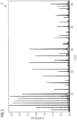
Figure 3 exemplifies a measure of the response R to the vibration applied to themovable member 2. In particular, the measure comprises an amplitude A of a resonance of themovable member 2 with respect to a frequency f. That is, one or more vibrations at different frequencies may be applied to themovable member 2 and a response R thereof over the frequency domain f may be measured and plotted. - The method may comprise:
- comparing the response R detected, e.g. the response R plotted in
figure 3 , to a predetermined vibration pattern, and - checking whether the response R differs from the predetermined vibration pattern, and
- if the response R substantially corresponds to the predetermined vibration pattern, resuming operation of the
movable member 2. - The predetermined vibration patter may comprise a predetermined healthy state frequency pattern or a mathematical/theoretical model.
- At installation, the vibration may be applied to each
movable member 2 to determine the predetermined vibration pattern. In other words, the method may comprise calibrating themovable member 2 at installation by applying one or more vibrations, e.g. a frequency sweep, to themovable member 2 to generate the predetermined vibration pattern. In addition or in alternative, the predetermined vibration pattern may be based on a standard response ofmovable members 2 of a specific type to vibration. - The step of checking whether the response R differs from the predetermined vibration pattern may comprise checking whether new resonances are plotted, e.g. a new amplitude A is plotted at a frequency f that is not present at said frequency f in the predetermined vibration pattern. In addition or in alternative, the step of checking whether the response R differs from the predetermined vibration pattern may comprise checking whether the resonances plotted differ of more than a predetermined amount with respect to the predetermined vibration pattern, e.g. one or more amplitudes A change of more than a predetermined amount at certain frequencies f with respect to amplitudes A at said certain frequencies f in the predetermined vibration pattern.
- Accordingly, the response R substantially corresponds to the predetermined vibration pattern if the amplitude A changes non-negligibly. In other words, the response R substantially corresponds to the predetermined vibration pattern if the amplitude A changes within a predetermined amount with respect to the predetermined vibration pattern. This way, it is possible to monitor the condition of the
movable member 2 also considering the noise that may occur due to the measurement of the vibration. - If the response R substantially corresponds, the method may comprise resuming operation of the
movable member 2. If a plurality ofmovable members 2 are present, the measuring of the condition may be applied on allmovable members 2 before resuming normal operation. - If one or more
movable members 2 show that the response R does not substantially correspond to the predetermined vibration pattern, the method may comprise transmitting an alert to a user interface and/or preventing resumption or further operation of themovable members 2. - In one or more embodiments, the method may be applied periodically. That is, the method may comprise periodically interrupting operation of the linear motor system to monitor the condition of the
movable members 2. For example, normal operation of the linear motor system may be interrupted every 500 hours to monitor the condition of themovable members 2. - Advantageously, the method according to one or more embodiments allows a precise monitoring of the condition of the
movable members 2 and parts thereof. For example, during operation, one or more elements of themovable members 2 may be configured to move relatively with respect to a body of themovable member 2. Such movement, over time, may create play and/or degradation of the movable elements. Such play and/or degradation may be detected by means of studying the frequency response of themovable members 2 to vibration. In fact, the play and/or degradation may generate new/different movements when themovable members 2 are solicitated. - One or more embodiments, as illustrated in
figure 4 , refer to a forming assembly 7 configured to form one or more objects 80. In the following, a non-limiting example of a packaging assembly 7 is depicted, configured to form and seal a plurality ofpacks 80 containing a pourable product, preferably a pourable food product, starting from a tube 8 of packaging material. Whereas hereinafter reference is made to a packaging assembly 7, it will be appreciated that such is merely a non-limiting example for the ease of understanding and conciseness. Different types of forming assemblies 7 can exist that are not packaging assemblies. All features described in the following, even though related to a packaging assembly 7, can apply more in general to the forming assembly 7. - A tube 8 is formed in known manner by longitudinally folding and sealing a web (not shown) of packaging material. Tube 8 is then filled from above by a pipe (not shown) with the pourable product and is fed through packaging assembly 7 along a straight advancing direction X. In detail, tube 8 extends along a straight longitudinal, e.g. vertical, axis parallel to direction X.
- The forming assembly 7, e.g. the packaging assembly 7, comprises a linear motor system according to one or more embodiments as described previously. Packaging assembly 1 comprises:
- a pair of
conveyors 70 arranged on respective lateral sides of tube 8, spaced apart with respect to one another, and configured to cooperate with tube 8; and - an
outlet conveyor 72, which is arranged belowconveyors 70 staggered with respect to axis X. - Each
conveyor 70 substantially comprises the endless track 1 and a plurality ofmovable members 2, preferably movable members, coupled to, and cyclically movable along, one respective track 1. Eachmovable member 2 is configured to cyclically slide along track 1 of therespective conveyor 70. A plurality ofmovable members 2 slides, in use, along each track 1. - The forming assembly, e.g. the packaging assembly 7, thus comprises:
- a pair of endless tracks 1 between which the tube 8 is fed along the (e.g. straight) advancement direction X;
- a pair of
movable members 2, each one of which movably coupled to, and cyclically movable along, one respective track 1, - a processing unit 3 configured to position the movable member at a monitoring region M of the track 1 and apply vibration to the
movable member 2. - The
movable member 2 comprises avibration sensor 22 configured to detect a response of themovable member 2 to the vibration applied thereon. - As illustrated in figure 9, the two tracks 1 define respective endless paths P, Q arranged on opposite sides of the tube 8. More specifically, paths P, Q comprise:
- respective operative branches P1, Q1, preferably rectilinear, between which tube 8 is fed and along which
movable members 2 cooperate with tube 8; and - respective return branches P2, Q2, along which
movable members 2 are detached from tube 8. - According to this preferred embodiment shown, paths P, Q are substantially oval-shaped.
- In use, when sliding along the respective operative branch P1, Q1, each
movable member 2 cooperates with a corresponding movable member 2 - i.e.movable members 2 mutually cooperates two by two - defining in this way a pair ofmovable members 2 facing each other and cooperating with one another and with tube 8 while sliding along operative branches P1, Q1. - Each pair of
movable members 2 is configured to cooperate with tube 8 to cyclically form and seal onerespective pack 80 at a time, and cut thepack 80 to separate thepack 80 from tube 8, as shown infigure 4 . - To this end, each
movable member 2 comprises, at one of its sides, a formingunit 202 and asealing unit 204 both configured to cooperate with tube 8 along the respective operative branches P1, Q1. - The forming
units 202 are configured to respectively cooperate withtube portions 82 of tube 8 to form at least corresponding pack portions, more in particular corresponding packs 80. For this purpose, each formingunit 202 is carried by, preferably mounted on, the respectivemovable member 2 in a movable manner. The formingunit 202 may preferably comprise a half-shell, presenting a C-shaped cross section and comprising aback wall 208 and a pair of lateral flaps 210. In the embodiment shown, flaps 210 are movably coupled towall 208. Theflaps 210 project from opposite lateral edges ofwall 208 when movable members move along operative branches P1, Q1, and are hinged to such edges. - In use, the half-shell of each forming
unit 202 is configured to sequentially and cyclically cooperate in contact withtube portions 82 so as to form at least pack portions ofrespective packs 80. - Each half-shell is linearly movable transversally, e.g. orthogonally, to direction X, i.e. along direction Y, towards tube 8, i.e. towards the
tube portion 82 that half-shell has to form. Each formingunit 202 comprises amovable element 207 linearly movable along direction Y, which carries a respective half shell. - Sealing
units 204 are configured to cooperate with tube 8 to sealtube portions 82 at predetermined, equally spaced, successive cross sections crosswise to direction X. Furthermore, sealingunits 204 are configured to cooperate with tube 8 to cutpacks 80 at the cross sections, to separatepacks 80 from one another. - On one side, each sealing
unit 204 is mounted downstream of the corresponding formingunit 202 of the respectivemovable member 2 along the respective path P, Q and comprises a counter-sealing device and an extractable cutting element, for example a knife (not illustrated). On the other side, each sealingunit 204 is mounted downstream of the corresponding formingunit 202 of the respectivemovable member 2 along the respective path P, Q and comprises a sealing device and a seat, adapted to receive the knife of the corresponding sealing device configured to cooperate with such counter-sealing device. Sealing devices may comprise ultrasonic, induction or inductive heating sealing devices. - As shown in figures 9, when forming
units 202 and sealingunits 204 are advanced by the respectivemovable members 2 along the respective operative branch P1, Q1, the respective half-shells, sealing devices and counter-sealing devices move back and forth along a direction Y between: - a closed position, or operative position, in which half-shells, sealing devices and counter-sealing devices cooperate with
respective tube portions 82 to form, seal and cutrespective packs 80; and - an open position, or idle position, in which half-shells, sealing devices and counter-sealing devices are detached from tube 8 or from the formed packs 80.
- When half-shells are in the operative (closed) position, flaps 210 of each half-shell rotate about the respective hinges, e.g. about an axis parallel to direction X, from a position in which they diverge from the
respective wall 208, to a position in which they are substantially orthogonal to thewall 208, face flaps 210 of the other half-shell carried by the correspondingmovable member 2 of the same pair and contact tube 8 to completely surround therespective tube portion 82 destined to form therespective pack 80. - When two half-shells of two respective forming
units 202 of a pair of cooperatingmovable members 2 are both in the operative (closed) position, they define a substantially prismatic cavity and accordingly control the volume and shape of onerespective pack 80 being formed. - When the counter-sealing device and sealing device of a pair of cooperating
movable members 2 are in the operative (closed) position, they cooperate with one another to heat-seal tube 8, so as to form a top sealing band and a bottom sealing band. Then, the respective cutting element is extracted, so as to cutpacks 80 between the top and bottom sealing band of twoadjacent packs 80 and separate formedpacks 80 from one another. - As exemplified in figure 9, a further movement occurs along direction X, between the sealing
unit 204 and the formingunit 202, to form a top and/or bottom of thepacks 80.
Claims (15)
- A method of monitoring a condition of a movable member (2) in a linear motor system comprising a track (1) and at least one movable member (2) coupled to the track (1) and configured to move along said track (1), the movable member (2) comprising a vibration sensor (22) thereon, the method comprising:- positioning the movable member (2) at a monitoring region (M) of the track (1),- applying vibration to the movable member (2), and- detecting a response (R) of the movable member (2) to the vibration by means of the vibration sensor (22).
- The method of claim 1, comprising:- comparing the response (R) detected to a predetermined vibration pattern, and- checking whether the response (R) differs from the predetermined vibration pattern, and- if the response (R) substantially corresponds to the predetermined vibration pattern, resuming operation of the movable member (2).
- The method of claim 2, comprising, if the response (R) fails to substantially correspond to the predetermined vibration pattern, transmitting an alert to a user interface and/or preventing resumption operation of the movable member (2).
- The method of any of claim 1 to 3, wherein applying vibration to the movable member (2) comprises applying a predetermined, preferably sinusoidal, motion profile (S1, S2) to the movable member (2).
- The method of any of the previous claims, wherein the monitoring region (M) comprises a linear region of the track (1) extending in a direction perpendicular to a gravity acceleration direction (G).
- The method of any of the previous claims, comprising applying a plurality of vibrations to the movable member (2), the vibrations having different frequencies (f1, f2), preferably between 0.5 Hz and 200 Hz.
- The method according to any of the previous claims, comprising periodically interrupting operation of the linear motor system to monitor the condition of the movable member (2).
- The method of any of the previous claims, comprising calibrating the movable member (2) at installation by applying at least a vibration to the movable member (2) to generate the predetermined vibration pattern.
- A computer program product loadable in the memory of at least one electronic control unit (3, 22) and comprising software code portions for performing the steps of the method of any of claims 1 to 8.
- A linear motor system, comprising:- a track (1),- at least one movable member (2) coupled to the track (1) and configured to move along said track (1),- a processing unit (3) configured to position the movable member at a monitoring region (M) of the track (1) and apply vibration to the movable member (2),
wherein the movable member (2) comprises a vibration sensor (22) configured to detect a response of the movable member to the vibration applied thereon. - The linear motor system of claim 10, wherein the monitoring region (M) comprises a region, preferably linear, where the movable member (2) would lie if no force was applied on the movable member (2) by the linear motor system.
- The linear motor system of claim 10 or claim 11, wherein the vibration sensor (22) comprises at least one inertial sensor, preferably comprising at least one motion sensor and at least one rotation sensor, and/or a position error sensor and/or a torque sensor.
- The linear motor system of any of claims 10 to 12, wherein the vibration sensor (22) is potted with epoxy resin and fixed to the movable member (2).
- A forming assembly (7) configured to form a plurality of objects (80) and comprising a linear motor system according to any of claims 10 to 13, the forming assembly (7) comprising:- a pair of endless tracks (1),- a pair of movable members (2), each one of which movably coupled to, and cyclically movable along, one respective track (1),- a processing unit (3) configured to position the movable member at a monitoring region (M) of the track (1) and apply vibration to the movable member (2),
wherein the movable member (2) comprises a vibration sensor (22) configured to detect a response (R) of the movable member (2) to the vibration applied thereon. - The forming assembly (7) of claim 14, comprising a packaging assembly configured to form and seal a plurality of packs (80) containing a pourable product starting from a tube (8) of packaging material, the packaging assembly comprising a pair of endless tracks (1) between which said tube (8) is fed along a straight advancement direction (X), and
wherein each movable member (2) of said pair of movable members (2) comprises a respective forming unit (202) and a respective sealing unit (204) linearly movable towards said tube (8), transversally to said advancement direction (X), to cyclically cooperate in contact with successive tube portions (82), so as to form and seal at least corresponding pack portions of respective packs (80), respectively.
Applications Claiming Priority (1)
| Application Number | Priority Date | Filing Date | Title |
|---|---|---|---|
| EP21189791 | 2021-08-05 |
Publications (2)
| Publication Number | Publication Date |
|---|---|
| EP4130913A1 true EP4130913A1 (en) | 2023-02-08 |
| EP4130913B1 EP4130913B1 (en) | 2025-06-11 |
Family
ID=77411545
Family Applications (1)
| Application Number | Title | Priority Date | Filing Date |
|---|---|---|---|
| EP22184662.9A Active EP4130913B1 (en) | 2021-08-05 | 2022-07-13 | A method of monitoring the condition of a movable member in a linear motor system, corresponding linear motor system, forming assembly and computer program product |
Country Status (5)
| Country | Link |
|---|---|
| US (1) | US20240295875A1 (en) |
| EP (1) | EP4130913B1 (en) |
| JP (1) | JP2024533937A (en) |
| CN (1) | CN117795443A (en) |
| WO (1) | WO2023011878A1 (en) |
Citations (1)
| Publication number | Priority date | Publication date | Assignee | Title |
|---|---|---|---|---|
| EP3628605A1 (en) * | 2018-09-27 | 2020-04-01 | Tetra Laval Holdings & Finance S.A. | Method of fault prediction in a packaging machine |
Family Cites Families (9)
| Publication number | Priority date | Publication date | Assignee | Title |
|---|---|---|---|---|
| US2911538A (en) * | 1956-01-23 | 1959-11-03 | Munz Otto John | Linear motor control |
| JP2000316206A (en) * | 1999-04-28 | 2000-11-14 | Shinko Electric Co Ltd | Track inspection cart |
| JP3786175B2 (en) * | 2000-08-25 | 2006-06-14 | 日本電気株式会社 | Portable measuring device |
| CN105960370A (en) * | 2013-12-05 | 2016-09-21 | 奥的斯电梯公司 | Motor drive for linear machines with distributed windings |
| JP6747757B2 (en) * | 2016-03-25 | 2020-08-26 | Thk株式会社 | Method for diagnosing rolling guide device status |
| US11759269B2 (en) * | 2018-08-20 | 2023-09-19 | Verb Surgical Inc. | Engagement and/or homing of a surgical tool in a surgical robotic system |
| CN111354565B (en) * | 2020-04-23 | 2021-06-29 | 乐清野岛机电有限公司 | Production line for automatic assembly and bonding of surface inductance core |
| CN112161803B (en) * | 2020-09-16 | 2022-09-13 | 上海市轴承技术研究所 | Rolling bearing life-span energy consumption testing machine under combined load |
| US11982585B2 (en) * | 2021-09-23 | 2024-05-14 | Rockwell Automation Technologies, Inc. | System and method for strain and acceleration based analytics in an independent cart system |
-
2022
- 2022-07-13 CN CN202280054570.1A patent/CN117795443A/en active Pending
- 2022-07-13 EP EP22184662.9A patent/EP4130913B1/en active Active
- 2022-07-13 WO PCT/EP2022/069592 patent/WO2023011878A1/en not_active Ceased
- 2022-07-13 JP JP2024501869A patent/JP2024533937A/en active Pending
- 2022-07-13 US US18/574,803 patent/US20240295875A1/en active Pending
Patent Citations (1)
| Publication number | Priority date | Publication date | Assignee | Title |
|---|---|---|---|---|
| EP3628605A1 (en) * | 2018-09-27 | 2020-04-01 | Tetra Laval Holdings & Finance S.A. | Method of fault prediction in a packaging machine |
Also Published As
| Publication number | Publication date |
|---|---|
| JP2024533937A (en) | 2024-09-18 |
| EP4130913B1 (en) | 2025-06-11 |
| WO2023011878A1 (en) | 2023-02-09 |
| CN117795443A (en) | 2024-03-29 |
| US20240295875A1 (en) | 2024-09-05 |
Similar Documents
| Publication | Publication Date | Title |
|---|---|---|
| JP6782015B2 (en) | Packaging machine | |
| CN113710581B (en) | Packaging machine and method for producing sealed packages | |
| EP3254979B1 (en) | Unit and method for forming/advancing a pack or a portion of a pack | |
| EP4130913B1 (en) | A method of monitoring the condition of a movable member in a linear motor system, corresponding linear motor system, forming assembly and computer program product | |
| US12552573B2 (en) | Linear motor system, corresponding forming assembly and method | |
| CN1174897C (en) | Multipole unit for processing textile packaging material in a food product packaging plant | |
| EP4130909B1 (en) | LINEAR MOTOR SYSTEM, CORRESPONDING SHAPING ARRANGEMENT AND METHOD | |
| WO2024008474A1 (en) | Inspection apparatus for a packaging machine and packaging machine having an inspection apparatus | |
| US20240317513A1 (en) | A linear motor system, corresponding forming assembly and method | |
| JP5758739B2 (en) | Transport device | |
| EP4410689B1 (en) | A movable member for a system for supporting production of packages, corresponding system, filling machine and method | |
| EP4592777A1 (en) | Method and apparatus for performing operations on a packaging material | |
| JP2006036328A (en) | Bag making and packaging machine | |
| JP7734938B2 (en) | packaging equipment | |
| EP4286822A1 (en) | Virtual sensing system for condition monitoring of a container packaging machine | |
| EP4711118A1 (en) | A packaging machine for producing sealed packages from a web of packaging material, corresponding method and computer program product | |
| CN219215661U (en) | Ultrasonic monitoring device and system | |
| BR102019008541B1 (en) | KIT FOR FITTING CLOSED FLEXIBLE BAGS | |
| JP2019196228A5 (en) | ||
| BR102019008541A2 (en) | bag fitting device | |
| JP2007062805A (en) | Vertical bag making and packaging machine and weighing packaging system | |
| JP2024533937A5 (en) |
Legal Events
| Date | Code | Title | Description |
|---|---|---|---|
| PUAI | Public reference made under article 153(3) epc to a published international application that has entered the european phase |
Free format text: ORIGINAL CODE: 0009012 |
|
| STAA | Information on the status of an ep patent application or granted ep patent |
Free format text: STATUS: THE APPLICATION HAS BEEN PUBLISHED |
|
| AK | Designated contracting states |
Kind code of ref document: A1 Designated state(s): AL AT BE BG CH CY CZ DE DK EE ES FI FR GB GR HR HU IE IS IT LI LT LU LV MC MK MT NL NO PL PT RO RS SE SI SK SM TR |
|
| STAA | Information on the status of an ep patent application or granted ep patent |
Free format text: STATUS: REQUEST FOR EXAMINATION WAS MADE |
|
| 17P | Request for examination filed |
Effective date: 20230808 |
|
| RBV | Designated contracting states (corrected) |
Designated state(s): AL AT BE BG CH CY CZ DE DK EE ES FI FR GB GR HR HU IE IS IT LI LT LU LV MC MK MT NL NO PL PT RO RS SE SI SK SM TR |
|
| GRAP | Despatch of communication of intention to grant a patent |
Free format text: ORIGINAL CODE: EPIDOSNIGR1 |
|
| STAA | Information on the status of an ep patent application or granted ep patent |
Free format text: STATUS: GRANT OF PATENT IS INTENDED |
|
| INTG | Intention to grant announced |
Effective date: 20250115 |
|
| P01 | Opt-out of the competence of the unified patent court (upc) registered |
Free format text: CASE NUMBER: APP_3093/2025 Effective date: 20250120 |
|
| GRAS | Grant fee paid |
Free format text: ORIGINAL CODE: EPIDOSNIGR3 |
|
| GRAA | (expected) grant |
Free format text: ORIGINAL CODE: 0009210 |
|
| STAA | Information on the status of an ep patent application or granted ep patent |
Free format text: STATUS: THE PATENT HAS BEEN GRANTED |
|
| AK | Designated contracting states |
Kind code of ref document: B1 Designated state(s): AL AT BE BG CH CY CZ DE DK EE ES FI FR GB GR HR HU IE IS IT LI LT LU LV MC MK MT NL NO PL PT RO RS SE SI SK SM TR |
|
| REG | Reference to a national code |
Ref country code: GB Ref legal event code: FG4D |
|
| REG | Reference to a national code |
Ref country code: CH Ref legal event code: EP |
|
| REG | Reference to a national code |
Ref country code: IE Ref legal event code: FG4D |
|
| REG | Reference to a national code |
Ref country code: DE Ref legal event code: R096 Ref document number: 602022015736 Country of ref document: DE |
|
| PG25 | Lapsed in a contracting state [announced via postgrant information from national office to epo] |
Ref country code: ES Free format text: LAPSE BECAUSE OF FAILURE TO SUBMIT A TRANSLATION OF THE DESCRIPTION OR TO PAY THE FEE WITHIN THE PRESCRIBED TIME-LIMIT Effective date: 20250611 Ref country code: FI Free format text: LAPSE BECAUSE OF FAILURE TO SUBMIT A TRANSLATION OF THE DESCRIPTION OR TO PAY THE FEE WITHIN THE PRESCRIBED TIME-LIMIT Effective date: 20250611 |
|
| PGFP | Annual fee paid to national office [announced via postgrant information from national office to epo] |
Ref country code: DE Payment date: 20250728 Year of fee payment: 4 |
|
| REG | Reference to a national code |
Ref country code: LT Ref legal event code: MG9D |
|
| PG25 | Lapsed in a contracting state [announced via postgrant information from national office to epo] |
Ref country code: NO Free format text: LAPSE BECAUSE OF FAILURE TO SUBMIT A TRANSLATION OF THE DESCRIPTION OR TO PAY THE FEE WITHIN THE PRESCRIBED TIME-LIMIT Effective date: 20250911 Ref country code: GR Free format text: LAPSE BECAUSE OF FAILURE TO SUBMIT A TRANSLATION OF THE DESCRIPTION OR TO PAY THE FEE WITHIN THE PRESCRIBED TIME-LIMIT Effective date: 20250912 |
|
| PGFP | Annual fee paid to national office [announced via postgrant information from national office to epo] |
Ref country code: IT Payment date: 20250731 Year of fee payment: 4 |
|
| REG | Reference to a national code |
Ref country code: NL Ref legal event code: MP Effective date: 20250611 |
|
| PG25 | Lapsed in a contracting state [announced via postgrant information from national office to epo] |
Ref country code: BG Free format text: LAPSE BECAUSE OF FAILURE TO SUBMIT A TRANSLATION OF THE DESCRIPTION OR TO PAY THE FEE WITHIN THE PRESCRIBED TIME-LIMIT Effective date: 20250611 |
|
| PG25 | Lapsed in a contracting state [announced via postgrant information from national office to epo] |
Ref country code: HR Free format text: LAPSE BECAUSE OF FAILURE TO SUBMIT A TRANSLATION OF THE DESCRIPTION OR TO PAY THE FEE WITHIN THE PRESCRIBED TIME-LIMIT Effective date: 20250611 |
|
| PGFP | Annual fee paid to national office [announced via postgrant information from national office to epo] |
Ref country code: AT Payment date: 20251020 Year of fee payment: 4 |
|
| PG25 | Lapsed in a contracting state [announced via postgrant information from national office to epo] |
Ref country code: RS Free format text: LAPSE BECAUSE OF FAILURE TO SUBMIT A TRANSLATION OF THE DESCRIPTION OR TO PAY THE FEE WITHIN THE PRESCRIBED TIME-LIMIT Effective date: 20250911 |
|
| PG25 | Lapsed in a contracting state [announced via postgrant information from national office to epo] |
Ref country code: LV Free format text: LAPSE BECAUSE OF FAILURE TO SUBMIT A TRANSLATION OF THE DESCRIPTION OR TO PAY THE FEE WITHIN THE PRESCRIBED TIME-LIMIT Effective date: 20250611 |
|
| PG25 | Lapsed in a contracting state [announced via postgrant information from national office to epo] |
Ref country code: NL Free format text: LAPSE BECAUSE OF FAILURE TO SUBMIT A TRANSLATION OF THE DESCRIPTION OR TO PAY THE FEE WITHIN THE PRESCRIBED TIME-LIMIT Effective date: 20250611 |
|
| PG25 | Lapsed in a contracting state [announced via postgrant information from national office to epo] |
Ref country code: PT Free format text: LAPSE BECAUSE OF FAILURE TO SUBMIT A TRANSLATION OF THE DESCRIPTION OR TO PAY THE FEE WITHIN THE PRESCRIBED TIME-LIMIT Effective date: 20251013 |
|
| REG | Reference to a national code |
Ref country code: AT Ref legal event code: MK05 Ref document number: 1802756 Country of ref document: AT Kind code of ref document: T Effective date: 20250611 |
|
| PG25 | Lapsed in a contracting state [announced via postgrant information from national office to epo] |
Ref country code: IS Free format text: LAPSE BECAUSE OF FAILURE TO SUBMIT A TRANSLATION OF THE DESCRIPTION OR TO PAY THE FEE WITHIN THE PRESCRIBED TIME-LIMIT Effective date: 20251011 |
|
| PG25 | Lapsed in a contracting state [announced via postgrant information from national office to epo] |
Ref country code: AT Free format text: LAPSE BECAUSE OF FAILURE TO SUBMIT A TRANSLATION OF THE DESCRIPTION OR TO PAY THE FEE WITHIN THE PRESCRIBED TIME-LIMIT Effective date: 20250611 Ref country code: SM Free format text: LAPSE BECAUSE OF FAILURE TO SUBMIT A TRANSLATION OF THE DESCRIPTION OR TO PAY THE FEE WITHIN THE PRESCRIBED TIME-LIMIT Effective date: 20250611 |
|
| PG25 | Lapsed in a contracting state [announced via postgrant information from national office to epo] |
Ref country code: CZ Free format text: LAPSE BECAUSE OF FAILURE TO SUBMIT A TRANSLATION OF THE DESCRIPTION OR TO PAY THE FEE WITHIN THE PRESCRIBED TIME-LIMIT Effective date: 20250611 |
|
| PG25 | Lapsed in a contracting state [announced via postgrant information from national office to epo] |
Ref country code: PL Free format text: LAPSE BECAUSE OF FAILURE TO SUBMIT A TRANSLATION OF THE DESCRIPTION OR TO PAY THE FEE WITHIN THE PRESCRIBED TIME-LIMIT Effective date: 20250611 |
|
| PG25 | Lapsed in a contracting state [announced via postgrant information from national office to epo] |
Ref country code: EE Free format text: LAPSE BECAUSE OF FAILURE TO SUBMIT A TRANSLATION OF THE DESCRIPTION OR TO PAY THE FEE WITHIN THE PRESCRIBED TIME-LIMIT Effective date: 20250611 |
|
| PG25 | Lapsed in a contracting state [announced via postgrant information from national office to epo] |
Ref country code: SK Free format text: LAPSE BECAUSE OF FAILURE TO SUBMIT A TRANSLATION OF THE DESCRIPTION OR TO PAY THE FEE WITHIN THE PRESCRIBED TIME-LIMIT Effective date: 20250611 |
|
| PG25 | Lapsed in a contracting state [announced via postgrant information from national office to epo] |
Ref country code: RO Free format text: LAPSE BECAUSE OF FAILURE TO SUBMIT A TRANSLATION OF THE DESCRIPTION OR TO PAY THE FEE WITHIN THE PRESCRIBED TIME-LIMIT Effective date: 20250611 |
|
| REG | Reference to a national code |
Ref country code: CH Ref legal event code: H13 Free format text: ST27 STATUS EVENT CODE: U-0-0-H10-H13 (AS PROVIDED BY THE NATIONAL OFFICE) Effective date: 20260224 |
|
| REG | Reference to a national code |
Ref country code: DE Ref legal event code: R097 Ref document number: 602022015736 Country of ref document: DE |
|
| PG25 | Lapsed in a contracting state [announced via postgrant information from national office to epo] |
Ref country code: LU Free format text: LAPSE BECAUSE OF NON-PAYMENT OF DUE FEES Effective date: 20250713 |
|
| REG | Reference to a national code |
Ref country code: BE Ref legal event code: MM Effective date: 20250731 |
|
| PG25 | Lapsed in a contracting state [announced via postgrant information from national office to epo] |
Ref country code: MC Free format text: LAPSE BECAUSE OF FAILURE TO SUBMIT A TRANSLATION OF THE DESCRIPTION OR TO PAY THE FEE WITHIN THE PRESCRIBED TIME-LIMIT Effective date: 20250611 |
|
| PG25 | Lapsed in a contracting state [announced via postgrant information from national office to epo] |
Ref country code: DK Free format text: LAPSE BECAUSE OF FAILURE TO SUBMIT A TRANSLATION OF THE DESCRIPTION OR TO PAY THE FEE WITHIN THE PRESCRIBED TIME-LIMIT Effective date: 20250611 |
|
| PG25 | Lapsed in a contracting state [announced via postgrant information from national office to epo] |
Ref country code: BE Free format text: LAPSE BECAUSE OF NON-PAYMENT OF DUE FEES Effective date: 20250731 |
|
| PLBE | No opposition filed within time limit |
Free format text: ORIGINAL CODE: 0009261 |
|
| STAA | Information on the status of an ep patent application or granted ep patent |
Free format text: STATUS: NO OPPOSITION FILED WITHIN TIME LIMIT |
|
| PG25 | Lapsed in a contracting state [announced via postgrant information from national office to epo] |
Ref country code: CH Free format text: LAPSE BECAUSE OF NON-PAYMENT OF DUE FEES Effective date: 20250731 |
|
| REG | Reference to a national code |
Ref country code: CH Ref legal event code: L10 Free format text: ST27 STATUS EVENT CODE: U-0-0-L10-L00 (AS PROVIDED BY THE NATIONAL OFFICE) Effective date: 20260423 |