EP4130888A1 - Image formation apparatus - Google Patents
Image formation apparatus Download PDFInfo
- Publication number
- EP4130888A1 EP4130888A1 EP21779843.8A EP21779843A EP4130888A1 EP 4130888 A1 EP4130888 A1 EP 4130888A1 EP 21779843 A EP21779843 A EP 21779843A EP 4130888 A1 EP4130888 A1 EP 4130888A1
- Authority
- EP
- European Patent Office
- Prior art keywords
- fixing liquid
- collection
- image forming
- forming apparatus
- supply tank
- Prior art date
- Legal status (The legal status is an assumption and is not a legal conclusion. Google has not performed a legal analysis and makes no representation as to the accuracy of the status listed.)
- Granted
Links
Images










Classifications
-
- G—PHYSICS
- G03—PHOTOGRAPHY; CINEMATOGRAPHY; ANALOGOUS TECHNIQUES USING WAVES OTHER THAN OPTICAL WAVES; ELECTROGRAPHY; HOLOGRAPHY
- G03G—ELECTROGRAPHY; ELECTROPHOTOGRAPHY; MAGNETOGRAPHY
- G03G15/00—Apparatus for electrographic processes using a charge pattern
- G03G15/20—Apparatus for electrographic processes using a charge pattern for fixing, e.g. by using heat
- G03G15/2096—Apparatus for electrographic processes using a charge pattern for fixing, e.g. by using heat using a solvent
-
- G—PHYSICS
- G03—PHOTOGRAPHY; CINEMATOGRAPHY; ANALOGOUS TECHNIQUES USING WAVES OTHER THAN OPTICAL WAVES; ELECTROGRAPHY; HOLOGRAPHY
- G03G—ELECTROGRAPHY; ELECTROPHOTOGRAPHY; MAGNETOGRAPHY
- G03G21/00—Arrangements not provided for by groups G03G13/00 - G03G19/00, e.g. cleaning, elimination of residual charge
- G03G21/16—Mechanical means for facilitating the maintenance of the apparatus, e.g. modular arrangements
- G03G21/1661—Mechanical means for facilitating the maintenance of the apparatus, e.g. modular arrangements means for handling parts of the apparatus in the apparatus
- G03G21/1676—Mechanical means for facilitating the maintenance of the apparatus, e.g. modular arrangements means for handling parts of the apparatus in the apparatus for the developer unit
-
- G—PHYSICS
- G03—PHOTOGRAPHY; CINEMATOGRAPHY; ANALOGOUS TECHNIQUES USING WAVES OTHER THAN OPTICAL WAVES; ELECTROGRAPHY; HOLOGRAPHY
- G03G—ELECTROGRAPHY; ELECTROPHOTOGRAPHY; MAGNETOGRAPHY
- G03G21/00—Arrangements not provided for by groups G03G13/00 - G03G19/00, e.g. cleaning, elimination of residual charge
- G03G21/16—Mechanical means for facilitating the maintenance of the apparatus, e.g. modular arrangements
- G03G21/18—Mechanical means for facilitating the maintenance of the apparatus, e.g. modular arrangements using a processing cartridge, whereby the process cartridge comprises at least two image processing means in a single unit
- G03G21/1803—Arrangements or disposition of the complete process cartridge or parts thereof
- G03G21/1814—Details of parts of process cartridge, e.g. for charging, transfer, cleaning, developing
-
- G—PHYSICS
- G03—PHOTOGRAPHY; CINEMATOGRAPHY; ANALOGOUS TECHNIQUES USING WAVES OTHER THAN OPTICAL WAVES; ELECTROGRAPHY; HOLOGRAPHY
- G03G—ELECTROGRAPHY; ELECTROPHOTOGRAPHY; MAGNETOGRAPHY
- G03G2221/00—Processes not provided for by group G03G2215/00, e.g. cleaning or residual charge elimination
- G03G2221/16—Mechanical means for facilitating the maintenance of the apparatus, e.g. modular arrangements and complete machine concepts
- G03G2221/163—Mechanical means for facilitating the maintenance of the apparatus, e.g. modular arrangements and complete machine concepts for the developer unit
Definitions
- the present disclosure relates to an image forming apparatus.
- an image forming apparatus includes a photosensitive drum, a developing device, a transfer device, a jetting device, and a collection tray.
- the jetting device jets fixing liquid for fixing toner to a sheet toward the sheet to which the toner has been transferred.
- the collection tray accommodates the fixing liquid that has not adhered to the sheet (see Patent Document 1 below).
- Patent Document 1 Japanese Patent Provisional Publication No. 2017-68103
- An image forming apparatus of the present disclosure includes a photosensitive drum, a developing device, a transfer device, a spraying device, and a collecting device.
- the developing device is configured to supply toner onto the photosensitive drum.
- the transfer device is configured to transfer the toner supplied onto the photosensitive drum onto a sheet.
- the spraying device is configured to spray a fixing liquid for fixing the toner onto the sheet toward the sheet onto which the toner has been transferred.
- the spraying device includes a housing and nozzles.
- the housing is capable of accommodating the fixing liquid.
- the nozzles are configured to jet the fixing liquid inside the housing.
- the collecting device is configured to collect the fixing liquid sprayed from the nozzles and did not adhere to the sheet.
- the collecting device includes a collection tray, a collection pipe, and a collection pump.
- the collection tray is capable of accommodating the fixing liquid.
- the collection pipe is connected to the collection tray and is configured to allow the fixing liquid in the collection tray to pass therethrough.
- the collection pump is configured to send the fixing liquid in the collection pipe toward the housing.
- the fixing liquid sprayed from the nozzles and not adhered to the sheet can be accommodated in the collection tray and sent to the housing through the collection pipe.
- the fixing liquid that has not adhered to the sheet can be collected and sprayed from the nozzles again.
- the spraying device may further include a nozzle electrode and a counter electrode.
- the nozzle electrode is configured to charge the fixing liquid inside the housing.
- the counter electrode is disposed at a distance from the nozzle electrode.
- the nozzles are disposed between the nozzle electrode and the counter electrode.
- the counter electrode may be disposed in the collection tray.
- the fixing liquid jet from the nozzles can be drawn into the collection tray by the counter electrode.
- the fixing liquid that has not adhered to the sheet can be reliably accommodated in the collection tray.
- the collection pump may be a gear pump.
- the image forming apparatus may further include a main body housing and a supplying device.
- the supplying device is configured to supply the fixing liquid to the housing.
- the supplying device includes a fixing liquid cartridge, a refill pipe, a supply tank, and a supply pipe.
- the fixing liquid cartridge is configured to accommodate the fixing liquid.
- the fixing liquid cartridge is attachable to the main body housing.
- the refill pipe is connected to the fixing liquid cartridge in a state where the fixing liquid cartridge is attached to the main body housing.
- the refill pipe is configured to allow the fixing liquid in the fixing liquid cartridge to pass therethrough.
- the supply tank is connected to the refill pipe.
- the supply tank is capable of accommodating the fixing liquid that has passed through the refill pipe.
- the supply pipe is connected to the supply tank.
- the supply pipe is configured to allow the fixing liquid in the supply tank to pass therethrough.
- the housing is connected to the supply pipe.
- the housing is capable of accommodating the fixing liquid that has passed through the supply pipe.
- the fixing liquid in the fixing liquid cartridge can be supplied to the housing through the supply tank.
- the fixing liquid in the supply tank constant, even if the amount of the fixing liquid in the fixing liquid cartridge decreases, the fixing liquid can be stably supplied to the housing.
- the collection pipe may be connected to the supply tank.
- the collection pump sends the fixing liquid in the collection pipe to the housing via the supply tank.
- the fixing liquid from the collection tray can be accommodated in the supply tank together with the fixing liquid from the fixing liquid cartridge.
- the fixing liquid from the collection tray can be reused while stabilizing the spraying of the fixing liquid from the nozzle.
- the image forming apparatus may include a refill pump.
- the refill pump is configured to send the fixing liquid in the refill pipe toward the supply tank.
- the refill pump may be a gear pump.
- the image forming apparatus may include a sensor and a control device.
- the sensor is configured to detect a position of a liquid surface of the fixing liquid in the supply tank.
- the control device is capable of executing a pump driving process and a pump stop process.
- the pump driving process the control device drives the refill pump to supply the fixing liquid from the fixing liquid cartridge to the supply tank when the position of the liquid surface of the fixing liquid in the supply tank detected by the sensor is lower than a threshold value.
- the control device stops driving of the refill pump to stop the supplying of the fixing liquid from the fixing liquid cartridge to the supply tank when the position of the liquid surface of the fixing liquid in the supply tank detected by the sensor is equal to or higher than the threshold value.
- the amount of the fixing liquid in the supply tank can be made constant based on the position of the liquid surface detected by the sensor.
- control device may execute the pump driving process after finishing a print job.
- the image forming apparatus may further include a stirring member.
- the stirring member is configured to stir the fixing liquid in the supply tank.
- the collecting device may include a collection valve.
- the collection valve is configured to prevent the fixing liquid in the collection tray from passing through the collection pipe and being sent to the supply tank.
- the collection pipe may include a filter.
- At least a portion of the collection pipe may extend in a vertical direction.
- the filter may extend in a direction intersecting with the vertical direction.
- the fixing liquid can be brought into contact with the entire surface of the filter by causing the fixing liquid to pass through the filter in the vertical direction.
- the collection pipe may be connected to the refill pipe.
- the refill pipe allows the fixing liquid that has passed through the collection pipe to path therethrough.
- the image forming apparatus may include a collection tank and a second collection pipe.
- the collection tank is connected to the collection pipe.
- the collection tank is capable of accommodating the fixing liquid that has passed through the collection pipe.
- the second collection pipe is connected to the collection tank.
- the second collection pipe is configured to allow the fixing liquid in the collection tank to path therethrough.
- the housing may be connected to the second collection pipe.
- the housing may be capable of accommodating the fixing liquid that has passed through the second collection pipe.
- the housing may be connected to the refill pipe and the collection pipe, and may be capable of accommodating the fixing liquid that has passed through the refill pipe and the fixing liquid that has passed through the collection pipe.
- the control device may execute a collection process when execution of a print job is finished.
- the control device drives the collection pump to send the fixing liquid in the collection tray toward the housing.
- the fixing liquid in the collection tray can be sent to the housing.
- the fixing liquid that has not adhered to the sheet can be collected while suppressing grow in size of the collection tray.
- the control device may count a first cumulative number of pages being a cumulative number of pages printed after the previous collection process.
- the control device may lengthen a driving time of the collection pump in the collection process as the first cumulative number of pages increases.
- the time period for the collection process can be lengthened to reliably send the fixing liquid in the collection tray to the housing.
- the supplying device may include a supply tank and a sensor.
- the supply tank is configured to accommodate the fixing liquid to be supplied to the spraying device.
- the sensor is configured to detect whether or not an amount of the fixing liquid in the supply tank is less than a prescribed amount.
- the controller may store a first set value and a second set value.
- the first set value is a number of pages that can be continuously printed by the prescribed amount of the fixing liquid.
- the second set value is set based on a capacity of the collection tray.
- the collection tray can be prevented from overflowing by giving the collection process priority over a new print job.
- the waiting time for printing can be shortened by giving a new print job priority over the collection process.
- the control device may lengthen a driving time of the collection pump in the collection process as the first cumulative number of pages increases.
- the time period for the collection process can be lengthened by a time period corresponding to the number of pages printed in the new print job.
- the fixing liquid in the collection tray can be reliably sent to the housing.
- control device may abort execution of the print job and execute the collection process.
- the control device may reset the first cumulative number of pages when the collection process is completed.
- the supplying device may further include a fixing liquid cartridge, a refill pipe, and a refill pump.
- the fixing liquid cartridge is capable of accommodating the fixing liquid to be supplied to the supply tank.
- the refill pipe is connected to the fixing liquid cartridge and the supply tank.
- the refill pipe is configured to allow the fixing liquid moving from the fixing liquid cartridge to the supply tank to pass therethrough.
- the refill pump is configured to send the fixing liquid in the refill pipe toward the supply tank.
- control device may execute a refilling process.
- the control device drives the refill pump to send the fixing liquid accommodated in the fixing liquid cartridge to the supply tank.
- the fixing liquid is sent from the collection tray to the supply tank by the collection process after the supply tank becomes full by the refilling process, and the supply tank may overflow.
- control device may execute the refilling process.
- the control device may execute an error displaying process when the sensor does not detect that a second cumulative number of pages is equal to or greater than a third set value and the amount of the fixing liquid in the supply tank is less than the prescribed amount.
- the second cumulative number of pages is a cumulative number of pages printed after the previous refilling process.
- the control device causes a display device to display an error indication.
- the control device may execute the error displaying process when the second cumulative number of pages is equal to or greater than the third set value and the sensor does not detect that the amount of the fixing liquid in the supply tank is less than the prescribed amount after the execution of the print job is finished.
- the control device may execute the error displaying process when the second cumulative number of pages is equal to or greater than the third set value and the sensor does not detect that the amount of the fixing liquid in the supply tank is less than the prescribed amount during a warming-up process of the image forming apparatus.
- the control device may execute the error displaying process when the second cumulative number of pages is equal to or greater than the third set value and the sensor does not detect that the amount of the fixing liquid in the supply tank is less than the prescribed amount during a recovery process after the sheet stuck in the image forming apparatus is removed.
- the image forming apparatus may include an off instruction receiving part configured to receive an instruction to turn off power.
- the control device sprays the fixing liquid in the housing from the nozzles. Then, the control device drives the collection pump to send the fixing liquid in the collection tray toward the housing.
- the collection pump may be configured to send the fixing liquid in the collection pipe to the housing via the supply tank.
- the supplying device may include a first sensor.
- the first sensor is configured to detect an accommodation state of the fixing liquid in the housing.
- the control device causes the supply pump to supply the fixing liquid from the supply tank to the housing when a detection result of the first sensor indicates that a prescribed amount of the fixing liquid is not accommodated in the housing.
- the control unit supplies the fixing liquid from the tank to the housing, thereby enabling printing by the image forming apparatus.
- the image forming apparatus may include a second sensor configured to detect an accommodation state of the fixing liquid in the supply tank.
- the control device causes the refill pump to execute refilling of the supply tank with the fixing liquid from the fixing liquid cartridge when the detection result of the second sensor indicates that a prescribed amount of the fixing liquid is not accommodated in the supply tank.
- the control device refills the supply tank with the fixing liquid from the fixing liquid cartridge. Therefore, the supply of the fixing liquid from the supply tank to the housing and printing by the image forming apparatus becomes possible.
- the image forming apparatus may include a cancel instruction receiving part.
- the cancel instruction receiving part is configured to receive an instruction to cancel the collection process and an instruction to cancel the cancellation of the collection process.
- the control device does not execute the collection process until the cancel instruction receiving part subsequently receives the instruction to cancel the cancellation of the collection process.
- the spraying device may include a nozzle electrode and a counter electrode.
- the image forming apparatus may include a first voltage generating circuit, a second voltage generating circuit, and a current detection circuit.
- the nozzle electrode is configured to charge the fixing liquid in the housing.
- the counter electrode is disposed at a distance from the nozzle electrode to generate a potential difference between the nozzle electrode and the counter electrode.
- the first voltage generating circuit is connected to the nozzle electrode and is configured to generate a first voltage to be applied to the nozzle electrode.
- the second voltage generating circuit is connected to the counter electrode and is configured to generate a second voltage to be applied to the counter electrode.
- the current detection circuit is configured to detect a current flowing between the first voltage generating circuit and the nozzle electrode or between the second voltage generating circuit and the counter electrode.
- the control device controls the first voltage generating circuit and the second voltage generating circuit so that the potential difference between the nozzle electrode and the counter electrode becomes less than the prescribed value before spraying the fixing liquid from the nozzles. Furthermore, the control device calculates a resistance of a bypass circuit from the nozzle electrode to the counter electrode via the supplying device and the collecting device based on a current value detected by the current detection circuit and the potential difference between the nozzle electrode and the counter electrode less than the prescribed value.
- control device calculates a current value for correction from the potential difference between the nozzle electrode and the counter electrode equal to or greater than the prescribed value and the resistance of the bypass circuit when spraying the fixing liquid from the nozzles.
- the control device also controls the first voltage generating circuit and the second voltage generating circuit so that the potential difference between the nozzle electrode and the counter electrode becomes equal to or greater than the prescribed value, thereby causing the nozzles to spray the fixing liquid.
- the control device determines whether or not a current obtained by correcting the current value detected by the current detection circuit with the current value for correction is within a target current range, and when the corrected current value is outside the target current range, controls the first voltage generating circuit and the second voltage generating circuit so that the corrected current value falls within the target current range.
- a resistance in a state where a spraying current does not flow is a resistance of the bypass circuit that extends from the nozzle electrode to the counter electrode via the supplying device and the collecting device.
- the current value for correction is a current value that flows in the bypass circuit when the fixing liquid is sprayed.
- the current corrected with the current value for correction is a net spraying current when the fixing liquid is sprayed. Therefore, the control device can appropriately control a magnitude of the net spraying current by controlling the first voltage generating circuit and the second voltage generating circuit so that the current corrected with the correction current value falls within the target current range.
- the control device may determine whether or not a current value detected by the current detection circuit is within a corrected target current range obtained by correcting the target current range with the current value for correction, and when the current value is outside the corrected target current range, the control device may control the first voltage generating circuit and the second voltage generating circuit so that the current value falls within the corrected target current range.
- a resistance in a state where the spray current does not flow is a resistance of the bypass circuit that extends from the nozzle electrode to the counter electrode via the supplying device and the collecting device.
- the current value for correction is a current value that flows in the bypass circuit when the fixing liquid is sprayed.
- the corrected target current range corrected with the current value for correction is a target current range for the sum of the spraying current and the current flowing in the above-mentioned circuit. Therefore, the control device can appropriately control the magnitude of the net spraying current by controlling the first voltage generating circuit and the second voltage generating circuit so that the current value detected by the current detection circuit falls within the corrected target current range corrected with the current value for correction.
- the control device Before spraying the fixing liquid from the nozzles, the control device applies a negative voltage to the counter electrode using the second voltage generating circuit.
- the control device further controls the second voltage generating circuit while not causing the first voltage generating circuit to apply a voltage to the nozzle electrode so that the potential difference between the nozzle electrode and the counter electrode becomes less than the prescribed value.
- control device can generate a potential difference between the nozzle electrode and the counter electrode while not causing the nozzles to spray the fixing liquid.
- control device Before spraying the fixing liquid from the nozzles, the control device may apply a positive voltage to the nozzle electrode using the first voltage generating circuit, and may control the first voltage generating circuit while not causing the second voltage generating circuit to apply a voltage to the counter electrode so that the potential difference becomes less than the prescribed value.
- the image forming apparatus may include a voltage generating circuit including the first voltage generating circuit and the second voltage generating circuit.
- the first voltage generating circuit and the second voltage generating circuit can be formed as a single member, and thus the number of parts can be reduced.
- the supplying device may include a supply tank capable of accommodating the fixing liquid, and a refill pipe connected to the supply tank and configured to allow the fixing liquid accommodated in the supply tank to pass therethrough.
- the image forming apparatus of the present disclosure it is possible to collect the fixing liquid that has not adhered to the sheet.
- FIGS. 1 to 6 An image forming apparatus according to a first embodiment of the present invention will be described in detail with reference to FIGS. 1 to 6 .
- the image forming apparatus 1 includes a main body housing 2, a sheet cassette 3, a photosensitive drum 4, a charging device 5, an exposure device 6, a developing device 7, a transfer device 8, and a jetting device 9.
- the main body housing 2 accommodates the sheet cassette 3, the photosensitive drum 4, the charging device 5, the exposure device 6, the developing device 7, the transfer device 8, and the jetting device 9.
- the sheet cassette 3 can accommodate sheets S.
- the sheet S is, for example, printing paper.
- the sheet S is conveyed toward the photosensitive drum 4.
- the photosensitive drum 4 is rotatable about a drum axis A1.
- the photosensitive drum 4 extends along the drum axis A1.
- the photosensitive drum 4 has a cylindrical shape.
- the charging device 5 charges a surface of the photosensitive drum 4.
- the charging device 5 is a charging roller.
- the charging device 5 may be a scorotron charger.
- the exposure device 6 can expose the surface of the photosensitive drum 4. In a state where the surface of the photosensitive drum 4 is charged by the charging device 5, the exposure device 6 exposes the surface of the photosensitive drum 4, thereby forming an electrostatic latent image on the surface of the photosensitive drum 4.
- the exposure device 6 is specifically a laser scanning unit.
- the exposure device 6 may be an LED array.
- the developing device 7 supplies toner onto the photosensitive drum 4.
- the developing device 7 may be detachable from the main body housing 2.
- the developing device 7 has a developing housing 71 and a developing roller 72.
- the developing housing 71 can accommodate toner.
- the developing device 7 can accommodate toner.
- the toner contains toner particles and, if necessary, an external additive.
- the toner particles contain binder resin and, if necessary, coloring agent, pigment dispersing agent, release agent, magnetic material and charge control agent.
- the binder resin is the base of the toner particles.
- the binder resin binds components contained in the toner particles.
- the coloring agent imparts a desired color to the toner particles.
- the coloring agent is dispersed in the binder resin.
- the pigment dispersing agent improves dispersibility of the coloring agent.
- the charge control agent imparts charge to the toner particles.
- the charge may be either positive or negative.
- the external additive controls the charge, fluidity and storage stability of the toner particles.
- the developing roller 72 can supply toner in the developing housing 71 to the surface of the photosensitive drum 4.
- the developing roller 72 comes into contact with the photosensitive drum 4.
- the developing roller 72 may not be in contact with the photosensitive drum 4.
- the developing roller 72 is rotatable about a developing axis A2.
- the developing roller 72 extends along the developing axis A2.
- the developing roller 72 has a cylindrical shape.
- the transfer device 8 transfers the toner supplied onto the photosensitive drum 4 onto the sheet S.
- the transfer device 8 is in contact with the photosensitive drum 4.
- the transfer device 8 may not be in contact with the photosensitive drum 4.
- the transfer device 8 is a transfer roller.
- the transfer roller is rotatable about a transfer axis A3.
- the transfer roller extends along the transfer axis A3.
- the transfer roller has a cylindrical shape.
- the transfer device 8 may be a belt unit including a transfer belt.
- the jetting device 9 jets fixing liquid toward the sheet S onto which the toner has been transferred.
- the fixing liquid fixes the toner onto the sheet S.
- the fixing liquid can soften the binder resin of the toner.
- the fixing liquid is, for example, aliphatic monocarboxylic acid ester, aliphatic dicarboxylic acid ester, carbonic acid ester, or the like.
- the jetting device 9 is an electrostatic spray type jetting device.
- the jetting device 9 applies the fixing liquid to the sheet S by electrostatically spraying the fixing liquid toward the sheet S.
- the jetting device 9 includes a housing 91, a plurality of nozzle 92, a nozzle electrode 93, and a counter electrode 94.
- the housing 91 can accommodate the fixing liquid.
- the plurality of nozzle 92 extend downward from the housing 91. Each of the plurality of nozzle 92 communicates with an internal space of the housing 91. Each of the plurality of nozzle 92 jets the fixing liquid that is inside the housing 91.
- the plurality of nozzle 92 are disposed between the nozzle electrode 93 and the counter electrode 94.
- the nozzle electrode 93 is disposed inside the housing 91. A nozzle voltage is applied to the nozzle electrode 93. The nozzle electrode 93 charges the fixing liquid inside the housing 91. In other words, the nozzle electrode 93 charges the fixing liquid to be supplied to the plurality of nozzle 92. The fixing liquid charged by the nozzle electrode 93 is jet from each of the plurality of nozzle 92, thereby the fixing liquid jet from each of the plurality of nozzle 92 is atomized. That is, the jetting device 9 atomizes the fixing liquid. In other words, the jetting device 9 sprays the fixing liquid.
- the counter electrode 94 faces the plurality of nozzle 92 with a gap therebetween.
- the counter electrode 94 is disposed on a side opposite to the nozzle electrode 93 with respect to the plurality of nozzle 92.
- a counter voltage is applied to the counter electrode 94.
- the counter electrode 94 attracts the fixing liquid sprayed from each of the plurality of nozzle 92 by electrostatic force.
- the sheet S onto which the toner has been transferred passes between the plurality of nozzle 92 and the counter electrode 94. At this time, the fixing liquid sprayed from each of the plurality of nozzle 92 is applied to the sheet S.
- the sheet S to which the fixing liquid has been applied is discharged on an upper surface of the main body housing 2.
- the image forming apparatus 1 further includes a supplying device 11, a collecting device 12, and a control device 100.
- the supplying device 11 supplies the fixing liquid to the housing 91.
- the supplying device 11 includes a fixing liquid cartridge 111, a first supply pipe 112, a first supply pump 113, a first supply valve 114, a supply tank 115, a stirring member 116, a sensor 117, a second supply pipe 118, a second supply pump 119, and a second supply valve 120.
- the image forming apparatus 1 includes the first supply pump 113, the stirring member 116, and the sensor 117.
- the fixing liquid cartridge 111 accommodates the fixing liquid.
- the fixing liquid cartridge 111 is attachable to the main body housing 2.
- the first supply pipe 112 is connected to the fixing liquid cartridge 111 in a state where the fixing liquid cartridge 111 is attached to the main body housing 2.
- the other end of the first supply pipe 112 is connected to the supply tank 115.
- the fixing liquid in the fixing liquid cartridge 111 is sent to the supply tank 115 through the first supply pipe 112. That is, the first supply pipe 112 allows the fixing liquid in the fixing liquid cartridge 111 to pass therethrough.
- the first supply pipe 112 is an example of a refill pipe of the present invention.
- the first supply pump 113 sends the fixing liquid in the first supply pipe 112 toward the supply tank 115.
- the first supply pump 113 is arranged between one end of the first supply pipe 112 and the other end of the first supply pipe 112. In a state where the fixing liquid cartridge 111 is attached to the main body housing 2, the first supply pump 113 is arranged between the fixing liquid cartridge 111 and the supply tank 115.
- the first supply pump 113 is a gear pump.
- the first supply pump is an example of a refill pump of the present invention.
- the first supply valve 114 prevents the fixing liquid in the fixing liquid cartridge 111 from passing through the first supply pipe 112 and being sent to the supply tank 115.
- the first supply valve 114 is arranged between one end of the first supply pipe 112 and the other end of the first supply pipe 112. In a state where the fixing liquid cartridge 111 is attached to the main body housing 2, the first supply valve 114 is arranged between the fixing liquid cartridge 111 and the supply tank 115. In a state where the fixing liquid cartridge 111 is attached to the main body housing 2, the first supply valve 114 is arranged between the fixing liquid cartridge 111 and the first supply pump 113.
- the first supply pump 113 When the first supply pump 113 is driven in a state where the first supply valve 114 is open, the fixing liquid in the fixing liquid cartridge 111 passes through the first supply valve 114 and is sent to the supply tank 115. On the other hand, in a state where the first supply valve 114 is closed, the fixing liquid in the fixing liquid cartridge 111 cannot pass through the first supply valve 114. Therefore, the first supply valve 114 prevents the fixing liquid in the fixing liquid cartridge 111 from passing through the first supply pipe 112 and being sent to the supply tank 115.
- the first supply valve 114 is, for example, an electromagnetic valve.
- the supply tank 115 is connected to the other end of the first supply pipe 112.
- the supply tank 115 can accommodate the fixing liquid that has passed through the first supply pipe 112.
- the second supply pump 119 cannot make the pressure inside the housing 91 lower than the positive pressure that acts in accordance with the position of the liquid surface of the fixing liquid in the supply tank 115.
- the second supply pump is an example of a supply pump of the present invention.
- the supply tank 115 is disposed lower than the housing 91. Since the supply tank 115 is disposed lower than the housing 91, the pressure inside the housing 91 becomes negative with respect to the pressure inside the supply tank 115. Therefore, the second supply pump 119 can control the pressure inside the housing 91 to a desired pressure by controlling an amount of the fixing liquid to be sent to the housing 91.
- the stirring member 116 is disposed in the supply tank 115.
- the stirring member 116 stirs the fixing liquid in the supply tank 115.
- the sensor 117 detects the position of the liquid surface of the fixing liquid in the supply tank 115.
- the liquid surface of the fixing liquid in the supply tank 115 is away from the other end of the first supply pipe 112.
- the sensor 117 is, for example, a photo sensor.
- the sensor 117 may be a level sensor such as a float type level sensor.
- the second supply pipe 118 is connected to the supply tank 115.
- the other end of the second supply pipe 118 is connected to the housing 91.
- the housing 91 is connected to the second supply pipe 118.
- the fixing liquid in the supply tank 115 is sent to the housing 91 through the second supply pipe 118. That is, the second supply pipe 118 allows the fixing liquid in the supply tank 115 to pass therethrough.
- the housing 91 can accommodate the fixing liquid that has passed through the second supply pipe 118.
- the second supply pipe is an example of a supply pipe of the present invention.
- the second supply pump 119 sends the fixing liquid in the second supply pipe 118 toward the housing 91.
- the second supply pump 119 is arranged between one end of the second supply pipe 118 and the other end of the second supply pipe 118.
- the second supply pump 119 is arranged between the supply tank 115 and the housing 91.
- the second supply pump 119 is a gear pump.
- the second supply valve 120 prevents the fixing liquid in the supply tank 115 from passing through the second supply pipe 118 and being sent to the housing 91.
- the second supply valve 120 is arranged between one end of the second supply pipe 118 and the other end of the second supply pipe 118.
- the second supply valve 120 is arranged between the supply tank 115 and the housing 91.
- the second supply valve 120 is arranged between the second supply pump 119 and the housing 91.
- the second supply pump 119 is driven in a state where the second supply valve 120 is open, the fixing liquid in the supply tank 115 passes through the second supply valve and is sent to the housing 91.
- the second supply valve 120 prevents the fixing liquid in the supply tank 115 from passing through the second supply pipe 118 and being sent to the housing 91.
- the second supply valve 120 is, for example, an electromagnetic valve.
- the collecting device 12 collects the fixing liquid that has been jet from the plurality of nozzle 92 and has not adhered to the sheet S.
- the collecting device 12 includes a collection tray 121, a collection pipe 122, a collection pump 123, and a collection valve 124.
- the collection tray 121 can accommodate the fixing liquid that has been jet from the plurality of nozzle 92 and has not adhered to the sheet S.
- the collection tray 121 faces the plurality of nozzle 92 with a gap therebetween.
- the collection tray 121 is disposed on a side opposite to the nozzle electrode 93 with respect to the plurality of nozzle 92.
- the counter electrode 94 is disposed in the collection tray 121. Therefore, the fixing liquid jet from the plurality of nozzle 92 can be drawn into the collection tray 121 by the counter electrode 94. As a result, the fixing liquid that has not adhered to the sheet S can be reliably accommodated in the collection tray 121.
- One end of the collection pipe 122 is connected to the collection tray 121.
- the other end of the collection pipe 122 is connected to the supply tank 115.
- the fixing liquid in the collection tray 121 is sent to the supply tank 115 through the collection pipe 122. That is, the collection pipe 122 allows the fixing liquid in the collection tray 121 to pass therethrough.
- a portion of the collection pipe 122 extends vertically.
- the collection pipe 122 has a filter 125.
- the filter 125 is arranged between one end of the collection pipe 122 and the other end of the collection pipe 122.
- the filter 125 is arranged between the collection tray 121 and the supply tank 115.
- the filter 125 is disposed at a portion of the collection pipe 122 extending vertically.
- the filter 125 extends in a direction intersecting with the vertical direction.
- foreign matter such as toner or paper powder is mixed in the fixing liquid accommodated in the collection tray 121.
- the filter 125 allows the fixing liquid to pass therethrough but does not allow foreign matter mixed in the fixing liquid to pass therethrough.
- the filter 125 removes foreign matter mixed in the fixing liquid from the fixing liquid.
- the collection pump 123 sends the fixing liquid in the collection pipe 122 toward the supply tank 115.
- the fixing liquid in the supply tank 115 is sent to the housing 91 through the second supply pipe 118. That is, the collection pump 123 sends the fixing liquid in the collection pipe 122 toward the jetting device 9 via the supply tank 115. In other words, the collection pump 123 sends the fixing liquid in the collection pipe 122 toward the housing 91.
- the collection pump 123 is arranged between one end of the collection pipe 122 and the other end of the collection pipe 122.
- the collection pump 123 is arranged between the collection tray 121 and the supply tank 115.
- the collection pump 123 is arranged between the filter 125 and the supply tank 115.
- the collection pump 123 is a gear pump.
- the collection valve 124 prevents the fixing liquid in the collection tray 121 from passing through the collection pipe 122 and being sent to the supply tank 115.
- the collection valve 124 is arranged between one end of the collection pipe 122 and the other end of the collection pipe 122.
- the collection valve 124 is arranged between the collection tray 121 and the supply tank 115.
- the collection valve 124 is arranged between the collection pump 123 and the supply tank 115.
- the control device 100 controls operations of the first supply pump 113, the second supply pump 119, and the collection pump 123.
- the control device 100 controls the opening and closing of the first supply valve 114, the second supply valve 120, and the collection valve 124.
- the control device 100 is can receive a signal transmitted by the sensor 117.
- the control device 100 is electrically connected to the first supply pump 113, the first supply valve 114, the second supply pump 119, the second supply valve 120, the collection pump 123, the collection valve 124, and the sensor 117.
- the control device 100 When a print job is received (S1), the control device 100 forms an image on the sheet S in accordance with the print job. When forming an image on the sheet S, the control device 100 causes the jetting device 9 to spray the fixing liquid (S2).
- control device 100 drives the second supply pump 119 in a state where the nozzle voltage is applied to the nozzle electrode 93 and the counter voltage is applied to the counter electrode 94. Then, the control device 100 opens the second supply valve 120 after the operation of the second supply pump 119 is stabilized.
- the fixing liquid is supplied to the housing 91 as the second supply valve 120 opens. The fixing liquid in the housing 91 is sprayed from each of the plurality of nozzle 92.
- the control device 100 stops the spraying of the fixing liquid from the jetting device 9 (S4).
- the control device 100 stops the second supply pump 119. Then, the control device 100 stops the application of the nozzle voltage to the nozzle electrode 93 and stops the application of the counter voltage to the counter electrode 94. The spraying of the fixing liquid from the jetting device 9 thereby stops.
- control device 100 executes a pump driving process (S6) and a pump stop process (S8), that is, the control device 100 executes the pump driving process (S3) and the pump stop process (S8) the pump stop process (S6) after the print job is finished (S3: YES).
- the control device 100 drives the first supply pump 113 to supply the fixing liquid from the fixing liquid cartridge 111 to the supply tank 115.
- the control device 100 opens the first supply valve 114 and drives the first supply pump 113 (S6). The fixing liquid is thereby supplied from the fixing liquid cartridge 111 to the supply tank 115.
- the control device 100 When the position of the liquid surface detected by the sensor 117 is equal to or higher than the threshold value (S5: NO), the control device 100 does not execute the pump driving process (S6).
- control device 100 executes the pump stop process (S8) after the pump driving process (S6).
- the control device 100 stops the driving of the first supply pump 113 in order to stop the supply of the fixing liquid from the fixing liquid cartridge 111 to the supply tank 115.
- the control device 100 stops the driving of the first supply pump 113 (S8) and closes the first supply valve 114. The supply of the fixing liquid from the fixing liquid cartridge 111 to the supply tank 115 thereby stops.
- the fixing liquid jet from the plurality of nozzle 92 and not adhered to the sheet S can be accommodated in the collection tray 121, sent to the supply tank 115 through the collection pipe 122, and sent from the supply tank 115 to the housing 91.
- the fixing liquid that has not adhered to the sheet S can be collected and jet again from the plurality of nozzle 92.
- the counter electrode 94 is disposed in the collection tray 121.
- the fixing liquid jet from the plurality of nozzle 92 can be drawn into the collection tray 121 with the counter electrode 94.
- the fixing liquid that has not adhered to the sheet S can be reliably collected in the collection tray 121.
- the fixing liquid in the fixing liquid cartridge 111 can be supplied to the housing 91 via the supply tank 115.
- the fixing liquid can be stably supplied to the housing 91 even if the amount of the fixing liquid in the fixing liquid cartridge 111 decreases.
- the collection pipe 122 is connected to the supply tank 115.
- the fixing liquid from the collection tray 121 can be accommodated in the supply tank 115 together with the fixing liquid from the fixing liquid cartridge 111.
- the fixing liquid from the collection tray 121 can be reused while stabilizing the jetting state of the fixing liquid from the plurality of nozzle 92.
- the supplying device 11 includes the sensor 117 that detects the position of the liquid surface of the fixing liquid in the supply tank 115.
- the control device 100 drives the first supply pump 113 (S6) to supply the fixing liquid from the fixing liquid cartridge 111 to the supply tank 115.
- the control device 100 stops the driving of the first supply pump 113 (S8) to stop the supplying of the fixing liquid from the fixing liquid cartridge 111 to the supply tank 115.
- the amount of the fixing liquid in the supply tank 115 can be made constant based on the position of the liquid surface detected by the sensor 117.
- the collection pipe 122 includes the filter 125.
- the fixing liquid can be reused by removing the foreign matter with the filter 125.
- a portion of the collection pipe 122 extends vertically.
- the filter 125 extends in the direction intersecting the vertical direction.
- the fixing liquid can be brought into contact with the entire surface of the filter 125 by causing the fixing liquid to pass through the filter 125 vertically.
- the collecting device 12 may be independent of the supplying device 11. Specifically, the collecting device 12 includes a collection tank 126 and a second collection pipe 127. In other words, the image forming apparatus 1 includes the collection tank 126 and the second collection pipe 127.
- the collection tank 126 is connected to the other end of the collection pipe 122.
- the collection tank 126 can accommodate the fixing liquid that has passed through the collection pipe 122.
- the collection tank 126 is disposed lower than the housing 91.
- the second collection pipe 127 is connected to the collection tank 126.
- the other end of the second collection pipe 127 is connected to the housing 91.
- the housing 91 is connected to the other end of the second collection pipe 127.
- the fixing liquid in the collection tank 126 is sent to the housing 91 through the second collection pipe 127. That is, the second collection pipe 127 allows the fixing liquid in the collection tank 126 to pass therethrough.
- the housing 91 can accommodate the fixing liquid that has passed through the second supply pipe 118 and the fixing liquid that has passed through the second collection pipe 127.
- the supplying device 11 may not include the supply tank 115.
- the collecting device 12 may be independent of the supplying device 11 and may not include the collection tank 126.
- the housing 91 is connected to the first supply pipe 112 and the collection pipe 122, and can accommodate the fixing liquid that has passed through the first supply pipe 112 and the fixing liquid that has passed through the collection pipe 122.
- the control device 100 may execute the pump driving process (S6) and the pump stop process (S8) while forming an image on the sheet S in accordance with the print job.
- the image forming apparatus 201 includes a main body housing 2, a sheet accommodating part 3, a photosensitive drum 4, a charging device 5, an exposure device 6, a developing device 7, a transfer device 8, and a spraying device 9.
- the main body housing 2 accommodates the sheet accommodating part 3, the photosensitive drum 4, the charging device 5, the exposure device 6, the developing device 7, the transfer device 8, and the spraying device 9.
- the sheet accommodating part 3 can accommodate the sheets S.
- the sheet S is, for example, printing paper.
- the sheet S is conveyed toward the transfer device 8.
- the sheet accommodating part 3 may be a sheet cassette attachable to the main body housing 2.
- the photosensitive drum 4 extends in a first direction, and is rotatable about a drum axis.
- the drum axis extends in the first direction.
- the charging device 5 charges a surface of the photosensitive drum 4.
- the charging device 5 is a charging roller.
- the charging device may be a scorotron type charger.
- the exposure device 6 can expose the surface of the photosensitive drum 4 charged by the charging device 5.
- the exposure device 6 is a laser scanning unit.
- the exposure device 6 may be an LED array.
- the developing device 7 supplies toner onto the photosensitive drum 4.
- the developing device 7 may be detachable from the main body housing 2.
- the developing device 7 has a developing housing 71 and a developing roller 72.
- the developing housing 71 can accommodate toner.
- the developing device 7 can accommodate toner.
- the toner contains toner particles and, if necessary, an external additive.
- the toner particles contain binder resin and, if necessary, coloring agent, pigment dispersing agent, release agent, magnetic material and charge control agent.
- the binder resin is the base of the toner particles.
- the binder resin binds components contained in the toner particles.
- the coloring agent imparts a desired color to the toner particles.
- the coloring agent is dispersed in the binder resin.
- the pigment dispersing agent improves dispersibility of the coloring agent.
- the charge control agent imparts charge to the toner particles.
- the charge may be either positive or negative.
- the external additive controls the charge, fluidity and storage stability of the toner particles.
- the developing roller 72 can supply toner in the developing housing 71 to the surface of the photosensitive drum 4.
- the developing roller 72 comes into contact with the photosensitive drum 4.
- the developing roller 72 may not be in contact with the photosensitive drum 4.
- the developing roller 72 extends in the first direction.
- the developing roller 72 is rotatable about a developing axis.
- the developing axis extends in the first direction.
- the transfer device 8 transfers toner on the photosensitive drum 4 to the sheet S.
- the transfer device 8 has a transfer roller 81.
- the transfer roller 81 is in contact with the photosensitive drum 4.
- the transfer roller 81 may not be in contact with the photosensitive drum 4.
- the transfer roller 81 extends in the first direction.
- the transfer roller 81 is rotatable about a transfer axis.
- the transfer axis extends in the first direction.
- the transfer device 8 may include a transfer belt.
- the spraying device 9 sprays the fixing liquid onto the sheet S onto which the toner has been transferred.
- the fixing liquid fixes the toner onto the sheet S.
- the fixing liquid can soften the binder resin of the toner.
- the fixing liquid is, for example, aliphatic monocarboxylic acid ester, aliphatic dicarboxylic acid ester, carbonic acid ester, or the like.
- the spraying device 9 is of an electrostatic spray type.
- the spraying device 9 sprays the fixing liquid toward the sheet S by electrostatic spraying.
- the spraying device 9 includes a housing 91, a plurality of nozzle 92, a nozzle electrode 93, and a counter electrode 94.
- the housing 91 can accommodate the fixing liquid.
- the plurality of nozzle 92 extend downward from the housing 91. Each of the plurality of nozzle 92 communicates with an internal space of the housing 91. Each of the plurality of nozzle 92 sprays the fixing liquid that is inside the housing 91.
- the plurality of nozzle 92 are disposed between the nozzle electrode 93 and the counter electrode 94.
- the nozzle electrode 93 is disposed inside the housing 91. A voltage is to be applied to the nozzle electrode 93.
- the nozzle electrode 93 charges the fixing liquid inside the housing 91. In other words, the nozzle electrode 93 charges the fixing liquid to be supplied to the plurality of nozzle 92.
- the counter electrode 94 faces the plurality of nozzle 92 with a gap therebetween.
- the counter electrode 94 is disposed on a side opposite to the nozzle electrode 93 with respect to the plurality of nozzle 92.
- a voltage having a polarity opposite to that of the voltage applied to the nozzle electrode 93 is applied to the counter electrode 94.
- a positive voltage is applied to the nozzle electrode 93, and a negative voltage is applied to the counter electrode 94.
- a potential difference (electric field) is generated between the nozzles 92 and the counter electrode 94, and the counter electrode 94 attracts the fixing liquid sprayed from each of the plurality of nozzle 92 by electrostatic force.
- the sheet S onto which the toner has been transferred passes between the plurality of nozzle 92 and the counter electrode 94. At this time, the fixing liquid is sprayed onto the sheet S from each of the plurality of nozzle 92. The sheet S onto which the fixing liquid has been sprayed is discharged onto an upper surface of the main body housing 2.
- the image forming apparatus 201 includes a supplying device 11, a collecting device 12, and a control device 200.
- the supplying device 11 can supply the fixing liquid to the housing 91 of the spraying device 9.
- the supplying device 11 includes a supply tank 115, a sensor 117, a supply pipe 118, a supply pump 119, a supply valve 120, a fixing liquid cartridge 111, a refill pipe 112, a refill pump 113, and a refill valve 114.
- the supply tank 115 can accommodate the fixing liquid to be supplied to the housing 91 of the spraying device 9.
- the sensor 117 detects whether an amount of the fixing liquid in the supply tank 115 is less than a prescribed amount or not.
- the prescribed amount is an amount that is less than the maximum amount of the fixing liquid that can be accommodated in the supply tank 115 and is an amount with which the supply tank 115 does not become empty even when the maximum number of sheets S that can be accommodated in the sheet accommodating part 3 is printed.
- the sensor 117 transmits a signal when it is detected that the amount of the fixing liquid in the supply tank 115 is equal to or more than the prescribed amount. When the sensor 117 is transmitting a signal, the sensor 117 is on. On the other hand, the sensor does not transmit the signal when it is detected that the amount of the fixing liquid in the supply tank 115 is less than the prescribed amount. When the sensor 117 is not transmitting the signal, the sensor 117 is off.
- the sensor 117 detects whether the amount of the fixing liquid in the supply tank 115 is less than the prescribed amount or not by detecting a position of a liquid surface of the fixing liquid in the supply tank 115.
- the sensor 117 is, for example, a photosensor.
- the sensor 117 may be a level sensor such as a float type level sensor.
- One end of the supply pipe 118 is connected to the supply tank 115.
- the other end of the supply pipe 118 is connected to the housing 91.
- the supply pipe 118 allows the fixing liquid going from the supply tank 115 toward the housing 91 to pass therethrough. Therefore, the fixing liquid in the supply tank 115 passes through the supply pipe 118 and enters the housing 91.
- the supply pump 119 sends the fixing liquid in the supply pipe 118 toward the housing 91.
- the supply pump 119 is arranged between one end of the supply pipe 118 and the other end of the supply pipe 118.
- the supply pump 119 is arranged between the supply tank 115 and the housing 91.
- the supply pump 119 is, for example, a gear pump.
- the supply valve 120 is arranged between one end of the supply pipe 118 and the other end of the supply pipe 118.
- the supply valve 120 is arranged between the supply tank 115 and the housing 91.
- the supply valve 120 is arranged between the supply pump 119 and the housing 91.
- the supply valve 120 is, for example, an electromagnetic valve.
- the fixing liquid cartridge 111 can accommodate the fixing liquid to be supplied to the supply tank 115.
- the fixing liquid cartridge 111 can be attached to the main body housing 2.
- the fixing liquid cartridge 111 attached to the main body housing 2 can be detached from the main body housing 2.
- one end of the refill pipe 112 is connected to the fixing liquid cartridge 111.
- the other end of the refill pipe 112 is connected to the supply tank 115.
- the refill pipe 112 allows the fixing liquid going from the fixing liquid cartridge 111 toward the supply tank 115 to pass therethrough. Therefore, the fixing liquid in the fixing liquid cartridge 111 passes through the refill pipe 112 and enters the supply tank 115.
- the refill pump 113 sends the fixing liquid in the refill pipe 112 toward the supply tank 115.
- the refill pump 113 is arranged between one end of the refill pipe 112 and the other end of the refill pipe 112. In a state where the fixing liquid cartridge 111 is attached to the main body housing 2, the refill pump 113 is arranged between the fixing liquid cartridge 111 and the supply tank 115.
- the refill pump 113 is, for example, a gear pump.
- the refill valve 114 is arranged between one end of the refill pipe 112 and the other end of the refill pipe 112. In a state where the fixing liquid cartridge 111 is attached to the main body housing 2, the refill valve 114 is arranged between the fixing liquid cartridge 111 and the supply tank 115. In a state where the fixing liquid cartridge 111 is attached to the main body housing 2, the refill valve 114 is arranged between the fixing liquid cartridge 111 and the refill pump 113.
- the refill pump 113 When the refill pump 113 is driven in a state where the refill valve 114 is open, the fixing liquid in the refill pipe 112 passes through the refill valve 114. On the other hand, in a state where the refill valve 114 is closed, the fixing liquid in the refill pipe 112 cannot pass through the refill valve 114. Therefore, the refill valve 114 prevents the fixing liquid in the fixing liquid cartridge 111 from passing through the refill pipe 112.
- the refill valve 114 is, for example, an electromagnetic valve.
- the collecting device 12 can collect the fixing liquid that has been sprayed from the spraying device 9 and has not adhered to the sheet S.
- the collecting device 12 includes a collection tray 121, a collection pipe 122, a collection pump 123, and a collection valve 124.
- the collection tray 121 can accommodate the fixing liquid that has been jet from the plurality of nozzle 92 and has not adhered to the sheet S.
- the collection tray 121 faces the plurality of nozzle 92 with a gap therebetween.
- the collection tray 121 is disposed on a side opposite to the nozzle electrode 93 with respect to the plurality of nozzle 92.
- the counter electrode 94 is disposed in the collection tray 121. Therefore, the fixing liquid sprayed from the plurality of nozzle 92 can be drawn into the collection tray 121 by the counter electrode 94. As a result, the fixing liquid that has not adhered to the sheet S can be reliably accommodated in the collection tray 121.
- One end of the collection pipe 122 is connected to the collection tray 121.
- the other end of the collection pipe 122 is connected to the supply tank 115.
- the other end of the collection pipe 122 may be connected to the fixing liquid cartridge 111.
- the collection pipe 122 allows the fixing liquid going from the collection tray 121 toward the supply tank 115 to pass therethrough. Therefore, the fixing liquid in the collection tray 121 passes through the collection pipe 122 and enters the supply tank 115.
- a portion of the collection pipe 122 extends vertically.
- the collection pipe 122 has a filter 125.
- the filter 125 is arranged between one end of the collection pipe 122 and the other end of the collection pipe 122.
- the filter 125 is arranged between the collection tray 121 and the supply tank 115.
- the filter 125 is disposed at a portion of the collection pipe 122 extending vertically.
- the filter 125 extends in a direction intersecting with the vertical direction.
- foreign matter such as toner or paper dust is mixed in the fixing liquid accommodated in the collection tray 121.
- the filter 125 allows the fixing liquid to pass therethrough but does not allow foreign matter mixed in the fixing liquid to pass therethrough.
- the filter 125 removes foreign matter mixed in the fixing liquid from the fixing liquid.
- the collection pump 123 sends the fixing liquid in the collection pipe 122 toward the supply tank 115.
- the collection pump 123 thereby sends the fixing liquid accommodated in the collection tray 121 toward the supplying device 11.
- the collection pump 123 is arranged between one end of the collection pipe 122 and the other end of the collection pipe 122.
- the collection pump 123 is arranged between the collection tray 121 and the supply tank 115.
- the collection pump 123 is arranged between the filter 125 and the supply tank 115.
- the collection pump 123 is a gear pump.
- the collection valve 124 is arranged between one end of the collection pipe 122 and the other end of the collection pipe 122.
- the collection valve 124 is arranged between the collection tray 121 and the supply tank 115.
- the collection valve 124 is arranged between the collection pump 123 and the supply tank 115.
- the collection valve 124 is, for example, an electromagnetic valve.
- the control device 200 controls operations of the supply pump 119, the collection pump 123, and the refill pump 113.
- the control device 200 controls the opening and closing of the supply valve 120, the collection valve 124, and the refill valve 114.
- the control device 200 can receive a signal transmitted by the sensor 117.
- the control device 200 is electrically connected to the supply pump 119, the supply valve 120, the collection pump 123, the collection valve 124, the refill pump 113, the refill valve 114, and the sensor 117.
- the control device 200 stores a first set value P1, a second set value P2, and a third set value P3.
- the control device 200 has a processor and a non-volatile memory.
- the non-volatile memory stores the first set value P1, the second set value P2, and the third set value P3.
- the first set value P1 is the number of pages that can be continuously printed until the supply tank 115 becomes empty.
- the first set value P1 is set based on the capacity of the supply tank 115.
- the first set value P1 is, for example, the number of pages that is expected to make the supply tank 115 in a full state empty.
- the supply tank 115 in the full state is a state in which the supply tank 115 holds the fixing liquid at a level at which the state of the sensor 117 changes from off to on.
- the supply tank 115 in the full state is a state in which a prescribed amount of the fixing liquid is accommodated in the supply tank 115. That is, the first set value P1 is the number of pages that can be continuously printed using the prescribed amount of the fixing liquid in the supply tank 115.
- the first set value P1 is set based on a normal amount of the fixing liquid used to print one page which is set in advance based on experiments, simulations, or the like, and the amount of the fixing liquid in the supply tank 115 in the full state which is set in advance based on the capacity of the supply tank 115.
- the first set value P1 is set to the same value as the maximum number of sheets S that the sheet accommodating part 3 can accommodate.
- the second set value P2 is set based on the capacity of the collection tray 121.
- the second set value P2 is, for example, the number of pages that is expected to be printable until the amount of the fixing liquid in the collection tray 121 reaches 80% of the capacity of the collection tray 121 from an empty state.
- An amount of the fixing liquid collected in the collection tray 121 in printing one page is a value that is set in advance based on experiments, simulations, or the like, and the second set value P2 is set based on this value and the capacity of the collection tray 121.
- the second set value P2 is smaller than the first set value P1.
- the third set value P3 is the number of pages that is expected to change the state of the sensor 117 from on to off.
- the third set value P3 is a value that is set in advance through experiments or simulations based on the capacity of the supply tank 115, and is set by converting the amount of the fixing liquid in the supply tank 115 consumed from the state in which the supply tank 115 is full until the state of the sensor 117 changes to on into the number of pages.
- the third set value P3 is smaller than the first set value P1 and smaller than the second set value P2.
- control by the control device 200 will be described with reference to FIGS. 9 to 15 .
- the control device 200 prints an image on the sheet S in accordance with the print job.
- the print job includes a print command, print data to be printed on the sheet S, the number of pages, and the like.
- the control device 200 causes the spraying device 9 to spray the fixing liquid (S202).
- control device 200 drives the supply pump 119 in a state where a voltage is applied to the nozzle electrode 93 and a voltage is applied to the counter electrode 94. Then, the control device 200 opens the supply valve 120 after the operation of the supply pump 119 is stabilized. The fixing liquid is thereby supplied to the housing 91. The fixing liquid in the housing 91 is sprayed from each of the plurality of nozzle 92.
- the control device 200 counts the cumulative number of printed pages, and defines the cumulative number of printed pages as a first cumulative number of pages C1.
- the control device 200 stops the spraying of the fixing liquid from the spraying device 9 (S205).
- control device 200 closes the supply valve 120 and then stops the supply pump 119. Then, the control device 200 stops the application of the voltage to the nozzle electrode 93 and stops the application of the voltage to the counter electrode 94. The spraying of the fixing liquid from the spraying device 9 thereby stops.
- the control device 200 starts a collection process (S206). That is, when the execution of the print job is finished (S204: YES), the control device 200 executes the collection process (S206).
- control device 200 drives the collection pump 123 to send the fixing liquid in the collection tray 121 to the supply tank 115 of the supplying device 11.
- control device 200 may send the fixing liquid in the collection tray 121 to the fixing liquid cartridge 111 of the supplying device 11.
- control device 200 drives the collection pump 123. Then, the control device 200 opens the collection valve 124 after the operation of the collection pump 123 is stabilized. The fixing liquid in the collection tray 121 is thereby sent to the supply tank 115.
- the new print job is herein defined as an interrupting job.
- control device 200 closes the collection valve 124 and then stops the collection pump 123.
- the flow of the fixing liquid from the collection tray 121 to the supply tank 115 thereby stops and the collection process ends.
- the control device 200 resets the first cumulative number of pages C1 (S209). That is, the next first cumulative number of pages C1 is the cumulative number of pages printed after the current first cumulative number of pages C1 is reset. In other words, the first cumulative number of pages C1 is the cumulative number of pages printed after the previous collection process.
- the control device 200 executes the collection process after executing the interrupting job (S226).
- control device 200 aborts the collection process and causes the spraying device 9 to spray the fixing liquid (S222).
- control device 200 stops the spraying of the fixing liquid from the spraying device 9 (S224).
- control device 200 executes collection process (S226).
- the control device 200 adds the number of pages N printed in the interrupting job to the first cumulative number of pages C1 (S225).
- the control device 200 lengthens the driving time of the collection pump 123 in the collection process as the first cumulative number of pages C1 increases.
- control device 200 resets the first cumulative number of pages C1 (S209, see FIG. 10 ).
- the control device 200 executes the interrupting job (S202, see FIG. 9 ) after the collection process (S228).
- control device 200 continues the collection process without executing the interrupting job, and finishes the collection process (S228).
- control device 200 resets the first cumulative number of pages C1 (S229) and executes the interrupting job (S202, see FIG. 9 ).
- the control device 200 aborts the print job (S231) and executes the collection process (S233).
- the control device 200 stops the spraying of the fixing liquid from the spraying device 9 (S231).
- control device 200 starts the collection process (S233).
- the control device 200 lengthens the driving time of the collection pump 123 in the collection process as the first cumulative number of pages C1 increases.
- control device 200 resets the first cumulative number of pages C1 (S235).
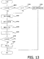
- FIG. 13 is a flowchart showing a recovery process of the image forming apparatus 201 when an error such as clogging of the sheet S occurred in the image forming apparatus 201 and the error is resolved by, for instance, removal of the clogged sheet S by the user.
- control device 200 executes the collection process (S243) after a nozzle cleaning (S242).
- the control device 200 executes the nozzle cleaning (S242).
- the control device 200 cleans the nozzles 92 by spraying the fixing liquid from the nozzles 92.
- the control device 200 executes the nozzle cleaning (S242).
- the second cumulative number of pages C2 is the cumulative number of pages printed after the previous refilling process. The refilling process will be described later.
- control device 200 starts the collection process (S243).
- the control device 200 lengthens the driving time of the collection pump 123 in the collection process as the first cumulative number of pages C1 increases.
- control device 200 resets the first cumulative number of pages C1 (S245).
- the control device 200 executes the refilling process (S211, S237, S247) In other words, when the sensor 117 detects that the amount of the fixing liquid in the supply tank 115 is less than the prescribed amount after the collection process, the control device 200 executes the refilling process.
- the control device 200 executes the refilling process (S253).
- the warming-up process is a process required until the image forming apparatus 201 becomes ready to execute printing after the image forming apparatus 201 is powered on.
- control device 200 drives the refill pump 113 to send the fixing liquid accommodated in the fixing liquid cartridge 111 to the supply tank 115.
- control device 200 drives the refill pump 113. Then, the control device 200 opens the refill valve 114 after the operation of the refill pump 113 is stabilized. The fixing liquid in the fixing liquid cartridge 111 is thereby sent to the supply tank 115.
- control device 200 ends the refilling of the supply tank with the fixing liquid from the fixing liquid cartridge 111 (S263).
- the control device 200 may change the prescribed time in accordance with the first cumulative number of pages C1. Specifically, the control device 200 may lengthen the prescribed time as the first cumulative number of pages increases.
- control device 200 closes the refill valve 114 and then stops the refill pump 113.
- the flow of the fixing liquid from the fixing liquid cartridge 111 to the supply tank 115 thereby stops and the refilling process ends.
- the control device 200 displays that the fixing liquid cartridge 111 is empty (S265).
- the control device 200 executes an error displaying process when a failure of the sensor 117 is suspected.
- the error displaying process is executed when the sensor 117 is on although it is expected that the sensor 117 turns off.
- the control device 200 executes the error displaying process (S213).
- the control device 200 executes the error displaying process.
- the control device 200 executes the error displaying process (S249) when the sensor 117 is on (S241: YES) and the second cumulative number of pages C2 is equal to or greater than the third set value P3 (S248: YES).
- the control device 200 executes the error displaying process when the second cumulative number of pages C2 is equal to or greater than the third set value P3 and the sensor 117 does not detect that the amount of the fixing liquid in the supply tank 115 is less than the prescribed amount.
- the control device 200 executes the error displaying process (S255) when the sensor 117 is on (S252: YES) and the second cumulative number of pages C2 is equal to or greater than the third set value P3 (S254: YES).
- the control device 200 executes the error displaying process when the second cumulative number of pages C2 is equal to or greater than the third set value P3 and the sensor 117 does not detect that the amount of the fixing liquid in the supply tank 115 is less than the prescribed amount.
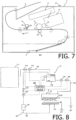
- the control device 200 causes a display device 21 provided on an outer surface of the main body housing 2 (see FIG. 7 ) to display an error indication indicating that the sensor 117 may have failed.
- the display device is not limited.
- the display device may be an LED, and the error indication indicating that the sensor 117 may have failed may be a blinking pattern of the LED.
- the display device may be a display of a personal computer connected to the image forming apparatus 201 via a local area network or the like, and an error message indicating that the sensor 117 may have failed may be displayed.
- the fixing liquid in the housing 91 is positively charged by the nozzle electrode 93 to which the positive voltage is applied.
- the fixing liquid in the supply tank 115 connected to the housing 91 is also positively charged.
- the fixing liquid in the collection tray 121 is negatively charged by the counter electrode 94 to which the negative voltage is applied.
- the negatively charged fixing liquid in the collection tray 121 will be collected in the supply tank 115 accommodating the positively charged fixing liquid.
- the collection process (S206) is executed after the execution of the print job is finished (S204: YES), the collection process during the execution of the print job can be suppressed and thus the decrease in the printing speed can be suppressed.
- control device 200 lengthens the driving time of the collection pump 123 in the collection process (S206) as the first cumulative number of pages C1 increases.
- the time of the collection process (S206) can be shortened to shorten waiting time for printing.
- the time of the collection process (S206) can be lengthened to reliably send the fixing liquid in the collection tray 121 to the supply tank 115.
- the collection tray 121 can be prevented from overflowing by giving priority to the collection process over the interrupting job.
- the control device 200 executes the collection process (S226) after the interrupting job (S223: YES).
- the collection tray 121 is less likely to overflow.
- the control device 200 lengthens the driving time of the collection pump 123 in the collection process (S226) as the first cumulative number of pages C1 increases.
- time of the collection process time can be lengthened by a time period corresponding to the number of pages printed in the interrupting job.
- the fixing liquid in the collection tray 121 can be reliably sent to the supply tank 115.
- the fixing liquid may be sent from the collection tray 121 to the supply tank 115 by the collection process after the supply tank 115 becoming full due to the refilling process, and the supply tank 115 may overflow.
- the failure of the sensor 117 can be displayed on the display device 30 (see FIG. 7 ).
- the fixing liquid remaining inside the accommodating part or on the collection tray may leak out due to vibration, impact, or inclination of the image forming apparatus when the image forming apparatus is moved or transported.
- FIG. 16 is a diagram showing a configuration of a laser printer 301 as an example of an image forming apparatus according to the third embodiment of the present invention.
- the laser printer 301 includes a main body housing 32, a feeder section 33 for feeding a paper P as an example of a recording sheet, and an image forming section 34 for forming an image on the paper P.
- the feeder section 33 includes a sheet feed tray 331 detachably mounted on a lower portion of the main body housing 32, and a sheet feed mechanism 332 that feeds the paper P in the sheet feed tray 331 toward the image forming section 34.
- the sheet feed mechanism 332 includes a sheet feed roller 332A, a separation roller 332B, a separation pad 332C, a paper dust removing roller 332D, and a registration roller 332E.
- the registration roller 332E is a roller that aligns a leading end position of the paper P, and can be stopped and rotated appropriately by a control unit 300 described later.
- the image forming section 34 is accommodated in the main body housing 32, and mainly includes a scanner unit 35, a process cartridge 36, a transfer roller TR, and a fixing device 37.
- the scanner unit 35 is provided at an upper portion inside the main body housing 32, and includes a laser emitting section, a polygon mirror, a lens, a reflecting mirror and the like which are not shown. In the scanner unit 35, a laser beam is irradiated onto a surface of a photosensitive drum 361 which will be described later by high-speed scanning.
- the process cartridge 36 is detachable from the main body housing 32.
- the process cartridge 36 includes the photosensitive drum 361 on which an electrostatic latent image is to be formed, a not-shown charger, a toner accommodating part 362 that accommodates toner, and a supply roller 363 and a developing roller 364 that supply toner inside the toner accommodating part 362 to the photosensitive drum 361.
- the not-shown charger uniformly charges the surface of the rotating photosensitive drum 361.
- the scanner unit 35 emits a laser beam to the surface of the photosensitive drum 361 to expose the surface of the photosensitive drum 361, thereby forming an electrostatic latent image based on image data on the surface of the photosensitive drum 361.
- the developing roller 364 which is driven to rotate, supplies toner to the electrostatic latent image on the photosensitive drum 361, thereby forming a toner image on the surface of the photosensitive drum 361. Then, the toner image carried on the surface of the photosensitive drum 361 is attracted by the transfer roller TR when the paper P is conveyed between the photosensitive drum 361 and the transfer roller TR, and is transferred onto the paper P.
- the fixing device 37 is a device that fixes the toner image on the paper P by supplying charged fixing liquid L to the toner image on the paper P by electrostatic spraying.
- the configuration of the fixing device 37 will be described in detail later.
- a pair of downstream-side conveying rollers Rd for nipping and conveying the paper P discharged from the fixing device 37 to the downstream side.
- the paper P conveyed by the downstream-side conveying rollers Rd is conveyed to a sheet discharge roller R, and is discharged from the sheet discharge roller R onto a sheet discharge tray 321.
- FIG. 17 is a diagram showing a specific configuration of the fixing device 37.
- the fixing device 37 includes a spraying unit 371, a supply unit 372, a collecting unit 373, and a control unit 300.
- the fixing device 37 further includes an air supply section 379, a first power source 378A, and a second power source 378B.
- the spraying unit 371 is an example of a spraying device of the present invention.
- the supply unit 372 is an example of a supplying device of the present invention.
- the collecting unit 373 is an example of a collecting device of the present invention.
- the control unit 300 is an example of a control device of the present invention.
- the spraying unit 371 sprays the fixing liquid L for fixing the toner transferred onto the paper P to the paper P.
- the spraying unit 371 has a housing 371A capable of accommodating the fixing liquid L, a nozzle electrode 371B that charges the fixing liquid L inside the housing 371A, a counter electrode 371C spaced apart from the nozzle electrode 371B, and nozzles 371D that spray the fixing liquid L inside the housing 371A to the paper P onto which the toner has been transferred when a potential difference between the nozzle electrode 371B and the counter electrode 371C is equal to or greater than a prescribed spraying potential difference (prescribed value).
- the fixing liquid L a solution in which a solute for dissolving the toner is dispersed in a solvent having a high dielectric constant can be used in order to favorably perform electrostatic spraying and perform fixing.
- the solvent having a high dielectric constant safe water can be used. That is, in the present embodiment, the toner is dissolved by a so-called oil-in-water type emulsion in which a solute for dissolving the toner is dispersed in water. That is, a fixing liquid formed by dispersing, in water, a solute which is insoluble or hardly soluble in water being a solvent. Surfactant may be added to favorably form emulsion.
- the supply unit 372 supplies the fixing liquid L to the spraying unit 371.
- the supply unit 372 has a tank 372A capable of accommodating the fixing liquid L, and a supply pipe 372B connected to the tank 372A and that allows the fixing liquid L accommodated in the tank 372A to pass therethrough.
- the tank 372A is an example of a supply tank of the present invention.
- the supply pipe 372B has a second liquid sending section 375 that controls the supply of the fixing liquid L.
- the supply pipe 372B is provided with a second pump 375B and a second valve 375A in this order from the tank 372A side.
- the second pump 375B has a function of pressurizing the fixing liquid L by sending the fixing liquid L from the tank 372A to the housing 371A, and is controlled by a motor.
- the second valve 375A has a function of adjusting a flow rate of the fixing liquid L supplied from the tank 372A to the housing 371A by using an electromagnetic valve.
- the second liquid sending section 375 does not necessarily need to include the second valve 375A, and may include the second pump 375B only.
- the second pump 375B is an example of a supply pump of the present invention.
- the supply unit 372 further has a cartridge 372C that accommodates the fixing liquid L, and a cartridge supply pipe 372D connected to the cartridge 372C and that allows the fixing liquid L accommodated in the cartridge 372C to pass therethrough.
- the cartridge 372C is an example of a fixing liquid cartridge of the present invention.
- the cartridge supply pipe 372D is an example of a refill pipe of the present invention.
- the cartridge supply pipe 372D has a fourth liquid sending section 377 that controls the supply of the fixing liquid L.
- the cartridge supply pipe 372D is provided with a fourth valve 377A and a fourth pump 377B in this order from the cartridge 372C side.
- the fourth valve 377A has a function of adjusting a flow rate of the fixing liquid L supplied from the cartridge 372C to the tank 372A by using an electromagnetic valve.
- the fourth pump 377B has a function of pressurizing the fixing liquid L by sending the fixing liquid L from the cartridge 372C to the tank 372A, and is controlled by a motor.
- the fourth liquid sending section 377 does not necessarily need to include the fourth valve 377A, and may include the fourth pump 377B only.
- the fourth pump 377B is an example of a refill pump of the present invention.
- the collecting unit 373 collects the fixing liquid L sprayed from the nozzles 371D but not adhered to the paper P.
- the collecting unit 373 has a collection tray 373A capable of accommodating the fixing liquid L, and a collection pipe 373B connected to the collection tray 373A and that allows the fixing liquid L in the collection tray 373A to pass therethrough.
- the housing 371A, the nozzle electrode 371B, and the nozzles 371D are disposed above the collection tray 373A.
- the nozzles 371D are disposed so as to spray the fixing liquid L downward.
- the counter electrode 371C is disposed in the collection tray 373A.
- the counter electrode 371C has a plurality of projection extending toward the nozzles 371D.
- the collection pipe 373B has a first liquid sending section 374 that sends the fixing liquid L to the tank 372A.
- the collection pipe 373B is provided with a first pump 374B and a first valve 374A in this order from the collection tray 373A side.
- the first pump 374B has a function of pressurizing the fixing liquid L by sending the fixing liquid L from the collection tray 373A to the tank 372A, and is controlled by a motor.
- the first valve 374A has a function of adjusting a flow rate of the fixing liquid L circulating from the collection tray 373A to the tank 372A by using an electromagnetic valve.
- the first liquid sending section 374 does not necessarily need to have the first valve 374A, and may have the first pump 374B only.
- a filter F for removing impurities from the fixing liquid L is provided to the collection pipe 373B between the collection tray 373A and the first liquid sending section 374.
- the first valve 374A is an example of a collection valve of the present invention.
- the first pump 374B is an example of a collection pump of the present invention.
- the first power source 378A is a constant current source that applies a voltage by inputting a current to the nozzle electrode 371B.
- the second power source 378B is a constant voltage source that applies a constant voltage to the counter electrode 371C.
- the air supply section 379 supplies air to the housing 371A.
- the air supply section 379 has a function of adjusting a flow rate of air flowing into the housing 371A by using an electromagnetic valve.
- the air supply section 379 In a state where the air supply section 379 is closed, air is not supplied to the housing 371A. Therefore, the fixing liquid L in the housing 371A does not go out from the nozzles 371D except when the voltage is applied to the nozzle electrode 371B and the counter electrode 371C.
- the air supply section 379 In a state where the air supply section 379 is open, air is supplied to the housing 371A. Therefore, atmospheric pressure acts on the fixing liquid L in the housing 371A, and the fixing liquid L is pushed out from the nozzles 371D and falls.
- the fixing device 37 further includes a first sensor Se1 capable of detecting an accommodating state of the fixing liquid L in the housing 371A and a second sensor Se2 capable of detecting an accommodating state of the fixing liquid L in the tank 372A.
- the first sensor Se1 is, for example, a pressure sensor that outputs a signal corresponding to the pressure by the fixing liquid L to the control unit 300
- the second sensor Se2 is, for example, a photoelectric sensor that outputs a signal having a magnitude corresponding to the amount of received light.
- FIG. 18 is a diagram showing a method for detecting the accommodating state of the fixing liquid L inside the tank 372A in case the second sensor Se2 is a photoelectric sensor.
- reference numeral 3001 indicates a state in which the amount of the fixing liquid L accommodated in the tank 372A is less than a prescribed amount
- reference numeral 3002 indicates a state in which the amount of the fixing liquid L accommodated in the tank 372A is equal to or greater than the prescribed amount.
- the tank 372A is provided with a float 381, a rotation shaft 382, a light-blocking part 383, and a light-projecting part 384.
- the float 381 is formed of a material floating on the fixing liquid L.
- the float 381 has a spherical shape but is not limited to this shape.
- the light-blocking part 383 is formed of a material that does not transmit light.
- the light-blocking part 383 has a plate-like shape but is not limited to this shape.
- the float 381 and the light-blocking part 383 are connected to the rotation shaft 382 such that their relative angle is constant. Therefore, as shown by reference numerals 3001 and 3002 in FIG. 18 , positions of the float 381 and the light-blocking part 383 change in accordance with the amount of the fixing liquid L accommodated in the tank 372A.
- the light-projecting part 384 and the second sensor Se2 are provided on a side wall of the tank 372A so as to face each other.
- the light-projecting part 384 emits light toward the second sensor Se2, and is a light-emitting diode, an infrared light emitter, or the like.
- the second sensor Se2 is provided at a position where the light from the light-projecting part 384 is blocked by the light-blocking part 383 when the amount of the fixing liquid L accommodated in the tank 372A is equal to or greater than a prescribed amount. Therefore, when the amount of the fixing liquid L accommodated in the tank 372A is equal to or greater than the prescribed amount, a signal output from the second sensor Se2 becomes weak.
- the laser printer 301 further includes an instruction receiving section 310.
- the instruction receiving section 310 receives instructions from a user to the laser printer 301.
- the instruction receiving section 310 includes an off instruction receiving part 311 and a moving mode switching instruction receiving part 312.
- the off instruction receiving part 311 receives an instruction to turn off the power of the laser printer 301.
- the off instruction receiving part 311 is a software-realized switch that generates an off signal upon receiving the instruction to turn off the power.
- the moving mode switching instruction receiving part 312 receives instructions to switch the moving mode on and off.
- the moving mode switching instruction receiving part 312 is an example of a cancel instruction receiving part of the present invention.
- the control unit 300 controls the first liquid sending section 374.
- the control unit 300 also controls a third liquid sending section 376, the fourth liquid sending section 377, and the air supply section 379.
- the control unit 300 integrally controls operation of the laser printer 301.
- FIG. 19 is a flowchart showing an example of processes in the fixing device 37.
- the control unit 300 executes a preparation process (SA). Contents of the preparation process will be described later.
- the control unit 300 determines whether or not a print instruction to print on the paper P has been received (S301). In a case where the print instruction to print on the paper P has been received (Yes in S301), the control unit 300 outputs a signal for driving the second liquid sending section 375 and the first liquid sending section 374 (S302). In this state, the control unit 300 executes printing (image formation) on the paper P (S303).
- SA preparation process
- control unit 300 outputs signals for generating a potential difference necessary for spraying the fixing liquid L between the nozzle electrode 371B and the counter electrode 371C to the first power source 378A and the second power source 378B, and sprays the fixing liquid L from the nozzles 371D toward the toner image on the paper P.
- the control unit 300 also outputs a signal for driving the fourth liquid sending section 377 as necessary to supply the fixing liquid L from the cartridge 372C to the tank 372A.
- the control unit 300 determines whether or not the printing has been finished (S304). If the printing process has not been finished (NO in S304), the control unit 300 continues spraying the fixing liquid L. If the printing process has been finished (YES in S304), the control unit 300 stops the second liquid sending section 375 and the first liquid sending section 374 (S305). Then, the control unit 300 repeats the processes from S301.
- the control unit 300 determines whether or not the off instruction receiving part 311 has received the instruction to turn off the power (S306). If the off instruction receiving part 311 has not received the instruction to turn off the power (NO in S306), the control unit 300 repeats the processes from S302.
- the control unit 300 determines whether or not the mode of the fixing device 37 is set to the moving mode (S307). If the mode of the fixing device 37 is set to the moving mode (YES in S307), the control unit 300 drives the first liquid sending section 374 and outputs a signal to open the air supply section 379 (S308) and waits for a certain period of time in this state (S309). Then, the control unit 300 stops the first liquid sending section 374, outputs a signal to close the air supply section 379 (S310), and turns off the power of the laser printer 301 (S311). On the other hand, if the mode of the fixing device 37 is not set to the moving mode (NO in S307), the control unit 300 turns off the power of the laser printer 301 (S311) without executing S308 to S310.
- FIG. 20 is a flow chart showing the contents of the "preparation process" in the flow chart shown in FIG. 19 .
- a state of the housing 371A or the tank 372A when a signal indicating the detection result of the first sensor Se1 or the second sensor Se2 indicates that a prescribed amount of the fixing liquid L is accommodated in the housing 371A or the tank 372A may be expressed as being "fully filled.”
- the control unit 300 determines whether or not the fixing device 37 is set in the moving mode (SA31). When the fixing device 37 is set in the moving mode (YES in SA31), the control unit 300 determines whether or not the tank 372A is fully filled with the fixing liquid L (SA32). When the tank 372A is fully filled with the fixing liquid L (YES in SA32), the control unit 300 outputs a signal for causing the second liquid sending section 375 to drive (SA33). The housing 371A is thereby filled with the fixing liquid L. When the tank 372A is not fully filled with the fixing liquid L (NO in SA32), the control unit 300 outputs a signal that causes the fourth liquid sending section 377 to drive (SA34). The tank 372A is thereby filled with the fixing liquid L. In this state, the control unit 300 executes SA33.
- the control unit 300 determines whether or not the housing 371A is fully filled with the fixing liquid L (SA35). When the fixing liquid L is not set in the moving mode (NO in SA35), the control unit 300 executes the processes of SA32 to SA34 as in the case where the fixing device 37 is set in the moving mode. When the housing 371A is fully filled with the fixing liquid L (YES in SA35), the control unit 300 ends the preparation process.
- the control unit 300 executes the following liquid sending process.
- the control unit 300 outputs, to the air feeding section 379, a signal for causing the fixing liquid in the housing 371A to be sprayed from the nozzles 371D, and outputs, to the first pump 374B, a signal for causing the fixing liquid L collected by the collecting unit 373 to be sent to the tank 372A.
- the control unit 300 also outputs, to the first valve 374A, a signal for causing the fixing liquid L to be sent to the tank 372A.
- the liquid sending process corresponds to S308 to S310 in the flowchart shown in FIG. 19 . This makes it possible to suppress the fixing liquid L remaining in the housing 371A or the collecting unit 373 from leaking when the power of the laser printer 1 is off. Then, at S311, the laser printer 301 is turned off.
- the air supply section 379 may further include a pump for supplying air from the outside to the housing 371A.
- the control unit 300 may drive the pump in accordance with the opening of the air supply section 379 and output a signal for causing the pump to stop in accordance with the closing of the air supply section 379.
- the control unit 300 When the laser printer 301 is activated, the control unit 300 outputs, to the second pump 375B, a signal for causing the fixing liquid L to be supplied from the tank 372A to the housing 371A in a case where the signal indicating the detection result of the first sensor Se1 indicates that the housing 371A does not accommodate the prescribed amount of the fixing liquid L.
- the control unit 300 also outputs, to the second valve 375A, a signal for causing the fixing liquid L to be supplied from the tank 372A to the housing 371A. This process corresponds to SA33 in the flowchart shown in FIG. 20 .
- the control unit 300 supplies the fixing liquid L from the tank 372A to the housing 371A. Therefore, printing on the paper P by the laser printer 301 becomes possible.
- the control unit 300 When the laser printer 301 is activated, the control unit 300 causes the fourth pump 377B to supply the fixing liquid L from the cartridge 372C to the tank 372A when the signal indicating the detection result of the second sensor Se2 indicates that the prescribed amount of the fixing liquid L is not accommodated in the tank 372A.
- the control unit 300 also outputs, to the fourth valve 377A, a signal for causing the fixing liquid L to be sent to the tank 372A. This process corresponds to SA34 in the flowchart shown in FIG. 20 .
- the control unit 300 causes the fixing liquid L to be supplied from the cartridge 372C to the tank 372A. Therefore, supply of the fixing liquid L from the tank 372A to the housing 371A and printing on the paper P by the laser printer 301 become possible.
- the control unit 300 does not execute the above-described liquid sending process from S308 to S310 until the moving mode switching instruction receiving part 312 receives an instruction to switch on the moving mode.
- the moving mode is a mode in which, when the power of the laser printer 301 is turned off to prepare for the movement of the laser printer 301 caused by the moving or the like, the fixing liquid L in the housing 371A and the like is sent to the tank 372A.
- the moving mode is set to on in the initial state of the laser printer 301.
- the liquid sending process is not executed. That is, the instruction to switch off the moving mode can be said to be an instruction to cancel the liquid sending process.
- the liquid sending process which was cancelled in the state where the moving mode is off, is executed. That is, the instruction to switch on the moving mode can be said to be an instruction to cancel the cancellation of the liquid sending process.
- the laser printer 301 it is possible to prevent the liquid sending process from being executed in accordance with the user's selection. Therefore, when the liquid sending process is unnecessary, it is possible to reduce: (i) time required for the liquid sending process when the power of the laser printer 301 is turned off, that is, time required to execute steps S308 to S310 in the flowchart shown in FIG. 19 , and (ii) time required for the supply of the fixing liquid L to the housing 371A and the like when the laser printer 301 is turned on, that is, time required to execute steps SA31 to SA35 in the flowchart shown in FIG. 20 .
- time required for the liquid sending process when the power of the laser printer 301 is turned off that is, time required to execute steps S308 to S310 in the flowchart shown in FIG. 19
- time required for the supply of the fixing liquid L to the housing 371A and the like when the laser printer 301 is turned on that is, time required to execute steps SA31 to SA35 in the flowchart shown in FIG. 20 .
- FIG. 21 is a diagram showing a configuration of a fixing device 37A according to the modification.
- the fixing device 37A device 37A differs from the fixing device 37 in that a second collecting unit 390 is provided in place of the collecting unit 373.
- the second collecting unit 390 has a collection tray 390A, a second collection tank 390B, and a second collection pipe 390C.
- the collection tray 390A has the same configuration as the collection tray 373A.
- the second collection tank 390B accommodates the fixing liquid accommodated in the collection tray 390A.
- the second collection pipe 390C is connected to the collection tray 390A and the second collection tank 390B, and allows the fixing liquid L in the collection tray 390A to pass therethrough. Since the fixing liquid L sent to the second collection tank 390B is not directly reused, the second collection pipe 390C is not provided with a filter.
- the second collection pipe 390C has a third liquid sending section 376 that controls collection of the fixing liquid L.
- the second collection pipe 390C is provided with a third valve 376A and a third pump 376B in this order from the collection tray 390A side.
- the third valve 376A has a function of adjusting a flow rate of the fixing liquid L to be collected from the collection tray 390A to the second collection tank 390B by using an electromagnetic valve.
- the third pump 376B has a function of pressurizing the fixing liquid L by sending the fixing liquid L from the collection tray 390A to the second collection tank 390B, and is controlled by, for example, a motor (not shown).
- the third liquid sending section 376 does not necessarily need to include the third valve 376A, and may include the third pump 376B only.
- a control unit 300A executes the following liquid sending process when the off instruction receiving part 311 receives the instruction to turn off the power.
- the control unit 300A causes the fixing liquid L in the housing 371A to be sprayed from the nozzles 371D, and outputs, to the third pump 376B, a signal for causing the fixing liquid L collected by the collection tray 390A to be sent from the collection tray 390A to the second collection tank 390B.
- the control unit 300A also outputs, to the third valve 376A, a signal for causing the fixing liquid L collected by the collection tray 390A to be sent to the second collection tank 390B.
- Such a fixing device 37A can also suppress leaking of the fixing liquid L remaining in the housing 371A or the collection tray 390A when the power of the laser printer 301 is off.
- control unit 300A Specific processes by the control unit 300A is basically the same as the processes by the control unit 300 shown in FIGS. 19 and 20 . However, in steps S302, S305, S308 and S310 shown in FIG. 19 , the control unit 300A outputs a signal for driving or stopping the third liquid sending section 376 in place of the signal for driving the first liquid sending section 374.
- Control blocks (particularly, the control units 300 and 300A) of the laser printer 301 and the fixing device 37 may be realized by a logic circuit (hardware) formed in an integrated circuit (IC chip) or the like, or may be realized by software.
- the laser printer 301 and the fixing device 37 include a computer that executes instructions of a program which is software for realizing each function.
- the computer includes, for example, one or more processors, and also includes a computer-readable recording medium storing the program.
- the processor reads the program from the recording medium and executes the program, thereby achieving the object of the present invention.
- a Central Processing Unit CPU
- the recording medium a "non-transitory physical medium" such as a Read Only Memory (ROM) or the like, a tape, a disk, a card, a semiconductor memory, a programmable logic circuit, or the like may be used.
- the recording medium may further include a Random Access Memory (RAM) or the like for developing the program.
- the program may be supplied to the computer via any transmission medium (communication network, broadcast wave, or the like) capable of transmitting the program.
- One aspect of the present invention may also be realized in the form of a data signal embedded in a carrier wave, in which the program is embodied by electronic transmission.
- FIG. 22 is a diagram showing a laser printer 401 as an example of an image forming apparatus according to the fourth embodiment of the present invention.
- the laser printer 401 includes a main body housing 42, a feeder section 43 for feeding a paper P as an example of a sheet, and an image forming section 44 for forming an image on the paper P.
- the feeder section 43 includes a sheet feed tray 431 detachably mounted on a lower portion of the main body housing 42, and a sheet feed mechanism 432 that feeds the paper P in the sheet feed tray 431 toward the image forming section 44.
- the sheet feed mechanism 432 includes a sheet feed roller 432A, a separation roller 432B, a separation pad 432C, a paper dust removing roller 432D, and a registration roller 432E.
- the registration roller 432E is a roller that aligns a leading end position of the paper P, and can be stopped and rotated appropriately by a control unit 400 described later.
- the image forming section 44 is accommodated in the main body housing 42, and mainly includes a scanner unit 45, a process cartridge 46, a transfer roller TR, and a fixing device 47.
- the scanner unit 45 is provided at an upper portion inside the main body housing 42, and includes a laser emitting section, a polygon mirror, a lens, a reflecting mirror and the like which are not shown. In the scanner unit 45, a laser beam is irradiated onto a surface of a photosensitive drum 461 which will be described later by high-speed scanning.
- the process cartridge 46 is detachable from the main body housing 42.
- the process cartridge 46 includes the photosensitive drum 461 on which an electrostatic latent image is to be formed, a not-shown charger, a toner accommodating part 462 that accommodates toner being an example of a developer, and a supply roller 463 and a developing roller 464 that supply toner inside the toner accommodating part 462 to the photosensitive drum 461.
- the not-shown charger uniformly charges the surface of the rotating photosensitive drum 461.
- the scanner unit 45 emits a laser beam to the surface of the photosensitive drum 461 to expose the surface of the photosensitive drum 461, thereby forming an electrostatic latent image based on image data on the surface of the photosensitive drum 461.
- the developing roller 464 which is driven to rotate, supplies toner to the electrostatic latent image on the photosensitive drum 461, thereby forming a toner image on the surface of the photosensitive drum 461. Then, the toner image carried on the surface of the photosensitive drum 461 is attracted by the transfer roller TR when the paper P is conveyed between the photosensitive drum 461 and the transfer roller TR, and is transferred onto the paper P.
- the fixing device 47 sprays the fixing liquid L onto the paper P on which the toner image is formed.
- the fixing device 47 is a device that supplies charged fixing liquid L to the toner image on the paper P by electrostatic spraying to fix the toner image on the paper P.
- the configuration of the fixing device 47 will be described in detail later.
- the fixing device 47 On the downstream side of the fixing device 47, there are provided a pair of downstream-side conveying rollers Rd that nip and convey the paper P discharged from the fixing device 47 to the downstream side.
- the paper P conveyed by the downstream-side conveying rollers Rd is conveyed to a sheet discharge roller R, and is discharged from the sheet discharge roller R onto a sheet discharge tray 321.
- the configuration of the fixing device 37 will be described in detail.
- FIG. 23 is a diagram showing a specific configuration of the fixing device 47.
- the fixing device 47 includes a spraying unit 471, a supply unit 472, a collecting unit 473, a first voltage generating circuit 475, a second voltage generating circuit 476, and a control unit 400.
- the spraying unit 471 is an example of a spraying device of the present invention.
- the supply unit 472 is an example of a supplying device of the present invention.
- the collecting unit 473 is an example of a collecting device of the present invention.
- the spraying unit 471 sprays the fixing liquid L for fixing the toner transferred onto the paper P to the paper P.
- the spraying unit 471 has a housing 471A capable of accommodating the fixing liquid L, a nozzle electrode 471B that charges the fixing liquid L inside the housing 471A, a counter electrode 471C spaced apart from the nozzle electrode 471B, and nozzles 471D that spray the fixing liquid L inside the housing 471A to the paper P onto which the toner has been transferred when a potential difference between the nozzle electrode 471B and the counter electrode 471C is equal to or greater than a prescribed spraying potential difference (prescribed value).
- the fixing liquid L a solution in which a solute for dissolving the toner is dispersed in a solvent having a high dielectric constant can be used in order to favorably perform electrostatic spraying and perform fixing.
- the solvent having a high dielectric constant safe water can be used. That is, in the present embodiment, the toner is dissolved by a so-called oil-in-water type emulsion in which a solute for dissolving the toner is dispersed in water. That is, a fixing liquid formed by dispersing, in water, a solute which is insoluble or hardly soluble in water being a solvent. Surfactant may be added to favorably form emulsion.
- the supply unit 472 supplies the fixing liquid L to the spraying unit 471.
- the supply unit 472 has a tank 472A capable of accommodating the fixing liquid L, and a supply pipe 472B connected to the tank 472A and that allows the fixing liquid L accommodated in the tank 472A to pass therethrough, a cartridge 472C, and a supply pipe 472D.
- the tank 472A is an example of a supply tank of the present invention.
- the cartridge 472C is an example of a fixing liquid cartridge of the present invention.
- the supply pipe 472B has a first liquid sending section 451 that controls the supply of the fixing liquid L.
- the supply pipe 472B is provided with a first pump 451B and a first valve 451A in this order from the tank 472A side.
- the first pump 451B has a function of pressurizing the fixing liquid L by sending the fixing liquid L from the tank 472A to the housing 471A, and is controlled by a motor.
- the first valve 451A has a function of adjusting a flow rate of the fixing liquid L supplied from the tank 472A to the housing 471A by using an electromagnetic valve.
- the first pump 451B is an example of a supply pump of the present invention.
- the collecting unit 473 collects the fixing liquid L sprayed from the nozzles 471D but not adhered to the paper P.
- the collecting unit 473 has a collection tray 473A capable of accommodating the fixing liquid L, and a collection pipe 473B connected to the collection tray 473A and that allows the fixing liquid L in the collection tray 473A to pass therethrough.
- the housing 471A, the nozzle electrode 471B, and the nozzles 471D are disposed above the collection tray 473A.
- the nozzles 471D are disposed so as to spray the fixing liquid L downward.
- the counter electrode 471C is disposed in the collection tray 473A.
- the counter electrode 471C has a plurality of projection extending toward the nozzles 471D.
- the collection pipe 473B has a second liquid sending section 452 that sends the fixing liquid L to the tank 472A.
- the collection pipe 473B is provided with a second pump 452B and a second valve 452A in this order from the collection tray 473A side.
- the second pump 452B has a function of pressurizing the fixing liquid L by sending the fixing liquid L from the collection tray 473A to the tank 472A, and is controlled by a motor.
- the second valve 452A has a function of adjusting a flow rate of the fixing liquid L circulating from the collection tray 473A to the tank 472A by using an electromagnetic valve.
- a filter F for removing impurities from the fixing liquid L is provided to the collection pipe 473B between the collection tray 473A and the second liquid sending section 452.
- the second valve 452A is an example of a collection valve of the present invention.
- the second pump 452B is an example of a collection pump of the present invention.
- the cartridge 472C is a tank that accommodates the fixing liquid L and is detachably attached to the main body housing 2.
- the supply pipe 472D is connected to the cartridge 472C and allows the fixing liquid L accommodated in the cartridge 472C to pass therethrough.
- the supply pipe 472D has a third liquid sending section 453 that controls the supply of the fixing liquid L.
- the supply pipe 472D is provided with a third valve 453A and a third pump 453B in this order from the cartridge 472C side.
- the third valve 453A has a function of adjusting a flow rate of the fixing liquid L supplied from the cartridge 472C to the tank 472A by using an electromagnetic valve.
- the third pump 453B has a function of pressurizing the fixing liquid L by sending the fixing liquid L from the cartridge 472C to the tank 472A, and is controlled by a motor.
- the third pump 453B is an example of a refill pump of the present invention.
- the supply pipe 472D is an example of a refill pipe of the present invention.
- the first voltage generating circuit 475 is connected to the nozzle electrode 471B and generates a first voltage to be applied to the nozzle electrode 471B.
- the first voltage generating circuit 475 is a constant current source that applies the first voltage V1 by outputting a constant first current I1 to the nozzle electrode 471B.
- the first voltage generating circuit 475 may also output a constant first voltage V1.
- the second voltage generating circuit 476 is connected to the counter electrode 471C and generates a second voltage to be applied to the counter electrode 471C.
- the second voltage generating circuit 476 is a constant voltage source that applies a constant second voltage V2 to the counter electrode 471C. At this time, a second current I2 flows from the counter electrode 471C to the second voltage generating circuit 476.
- the fixing device 47 has a voltage generating circuit 478 including the first voltage generating circuit 475 and the second voltage generating circuit 476. That is, the first voltage generating circuit 475 and the second voltage generating circuit 476 are formed on a single voltage generating circuit board. Therefore, the number of parts of the laser printer 401 can be reduced.
- the control unit 400 controls the first voltage generating circuit 475 and the second voltage generating circuit 476.
- description will be made while assuming that the control unit 400 controls the first voltage generating circuit 475 and the second voltage generating circuit 476 by Pulse Width Modulation (PWM) control.
- PWM Pulse Width Modulation
- the control unit 400 may control the first voltage generating circuit 475 and the second voltage generating circuit 476 by a control method other than the PWM control.
- the control unit 400 is an example of a control device of the present invention.
- the fixing device 47 shown in FIG. 23 is an image forming apparatus provided with a collection pipe 473B for returning the fixing liquid L collected by the collection tray 473A to the tank 472A that accommodates the fixing liquid L in order to reuse the fixing liquid L collected by the collecting unit 473.
- the fixing liquid in the collection pipe 473B and the fixing liquid L in the tank 472A may be linked via the fixing liquid adhered to an inner wall surface of the tank 472A near an inlet.
- a leakage current flows through a bypass circuit formed via the nozzle electrode 471B, the supply pipe 472B, the tank 472A, the collection pipe 473B, and the counter electrode 471C.
- control unit 400 calculates a resistance (circulation resistance Rcir) of the bypass circuit based on the value of the first current I1 or the second current I2 when the fixing liquid L is not sprayed by the nozzles N.
- Rcir circulation resistance
- FIG. 24 is a diagram showing the bypass circuit in the fixing device 47.
- the bypass circuit is a circuit extending from the nozzle electrode 471B to the counter electrode 471C through the supply pipe 472B, the tank 472A, the collection pipe 473B, and the collection tray 473A, as indicated by an arrow in FIG. 24 .
- the fixing liquid L in the collection pipe 473B and the fixing liquid L in the tank 472A are separated from each other, these fixing liquids L are insulated from each other, and thus no current flows in the bypass circuit.
- a current Icirleak flows in the bypass circuit.
- FIG. 25 is a circuit diagram showing a schematic configuration of the first voltage generating circuit 475 and the second voltage generating circuit 476 controlled by the control unit 400. An equivalent electric circuit between the nozzle electrode 471B and the counter electrode 471C is also shown in FIG. 25 .
- a current In accompanying the spraying of the fixing liquid L flows between the nozzle electrode 471B and the counter electrode 471C.
- the current In accompanying the spraying is expressed as a current flowing through a resistor Rs connected in parallel with the circulating resistor Rcir. Since the current In accompanying the spraying is a current corresponding to an amount of the fixing liquid L sprayed per unit time, the laser printer 401 performs control so that the current In accompanying the spraying falls within a set target current range in order to obtain a required spray state.
- the first voltage generating circuit 475 is a DC-DC converter that chops a DC voltage VCC1 connected to a primary side of a transformer T1 by a switching element Q1 and outputs a DC power obtained by voltage conversion through a rectifying and smoothing circuit connected to a secondary side of the transformer T1.
- the first voltage generating circuit 475 can apply a positive voltage to the nozzle electrode 471B.
- the switching element Q1 On and off of the switching element Q1 is controlled by a switching control signal Ss1 generated by the control unit 400.
- the first voltage V1 which is an output voltage of the first voltage generating circuit 475 is proportionally divided by a resistor Rs_Bl1 and a shunt resistor Rs_FBv1 to be a first voltage signal Sv1.
- the first voltage V1 is monitored by the control unit 400 through the first voltage signal Sv1 which depends on a magnitude of the first voltage V1.
- the first current I1 which is an output current from the first voltage generating circuit 475 is monitored by the control unit 400 through a first current signal Si1 which is based on a voltage applied to a shunt resistor Rs_FBv1 by the first current I1. That is, the shunt resistor Rs_FBv1 configures a current detection circuit that generates the first current signal Si1.
- the second voltage generating circuit 476 is a DC-DC converter that chops a DC voltage VCC1 connected to a primary side of a transformer T2 by a switching element Q2 and outputs a DC power obtained by voltage conversion through a rectifying and smoothing circuit connected to a secondary side of the transformer T2.
- the second voltage generating circuit 476 can apply a negative voltage to the counter electrode 471C.
- the switching control signal Ss2 generated by the control unit 400.
- the second voltage V2 which is an output voltage of the second voltage generating circuit 476 is proportionally divided by a resistor Rc_Bl2 and a resistor Rc FBv2 to be a second voltage signal Sv2.
- the second voltage V2 is monitored by the control unit 400 through the second voltage signal Sv2 which depends on a magnitude of the second voltage V2.
- the second current I2 which is an output current from the second voltage generating circuit 476 is monitored by the control unit 400 through a second current signal Si2 which is based on a voltage applied to the shunt resistor Rc_FBi2. That is, the shunt resistor Rc_FBi2 configures a current detection circuit that generates the second current signal Si2.
- the control unit 400 refers to the magnitude of the first voltage V1 monitored in this manner and adjusts the switching control signal Ss1 to cause the first voltage generating circuit 475 to output the first voltage V1 of a required magnitude.
- the control unit 400 refers to the magnitude of the first current I1 or the second current I2 to adjust the switching control signal Ss1 to cause the first voltage generating circuit 475 to output the first current I1 of a required current value.
- the control unit 400 also refers to the magnitude of the second voltage V2 monitored in this manner and adjusts the switching control signal Ss2 to cause the second voltage generating circuit 476 to output the second voltage V2 of a required magnitude.
- the control unit 400 controls the first voltage generating circuit 475 and the second voltage generating circuit 476 so that the potential difference between the nozzle electrode 471B and the counter electrode 471C becomes less than the spraying potential difference. Then, the control unit 400 calculates the resistance of the bypass circuit from the value of the current detected by the current detection circuit and the potential difference between the nozzle electrode 471B and the counter electrode 471C.
- the control unit 400 before the spraying of the fixing liquid L with the nozzles 471D, applies a negative voltage to the counter electrode 471C using the second voltage generating circuit 476 while not causing the first voltage generating circuit 475 to apply a voltage to the nozzle electrode 471B, and controls the second voltage generating circuit 476 so that the potential difference between the nozzle electrode 471B and the counter electrode 471C becomes less than the spraying potential difference.
- the voltage applied to the counter electrode 471C by the control unit 400 using the second voltage generating circuit 476 is, for example, - 2kV.
- the control unit 400 can generate a potential difference between the nozzle electrode 471B and the counter electrode 471C while not causing the nozzles 471D to spray the fixing liquid L and calculate the resistance of the bypass circuit.
- the control unit 400 may apply a positive voltage to the nozzle electrode 471B using the first voltage generating circuit 475 while not causing he second voltage generating circuit 476 to apply a voltage to the counter electrode 471C, and may control the first voltage generating circuit 475 so that the potential difference between the nozzle electrode 471B and the counter electrode 471C becomes less than the spraying potential difference.
- the control unit 400 sets the voltage to be applied to the nozzle electrode 471B using the first voltage generating circuit 475 to, for example, 2kY.
- the control unit 400 can generate a potential difference between the nozzle electrode 471B and the counter electrode 471C while not causing the nozzles 471D to spray the fixing liquid L and calculate the resistance of the bypass circuit.
- the control unit 400 controls the first voltage generating circuit 475 and the second voltage generating circuit 476 so that the potential difference between the nozzle electrode 471B and the counter electrode 471C becomes equal to or greater than the spraying potential difference. At this time, the control unit 400 sets a target current range for a current value to be detected by a current detection circuit based on a preset target current value for spraying an appropriate amount of the fixing liquid L.
- the control unit 400 also calculates a current value Ifix for correction from the potential difference between the nozzle electrode 471B and the counter electrode 471C and the resistance of the bypass circuit. The control unit 400 determines whether or not a current value obtained by correcting the current value detected by the current detection circuit with the current value Ifix for correction is within the target current range, and when the corrected current value is outside the target current range, the control unit 400 controls the first voltage generating circuit 475 and the second voltage generating circuit 476 so that the corrected current value falls within the target current range.
- the control unit 400 calculates the corrected current value by subtracting the current value Ifix for correction from the current value detected by the current detection circuit.
- the corrected current value is a net current value flowing between the nozzle electrode 471B and the counter electrode 471C obtained by subtracting a current value flowing through the bypass circuit from the current value detected by the current detection circuit. Therefore, the net current value flowing between the nozzle electrode 471B and the counter electrode 471C can be made to fall within the target current range and the appropriate amount of the fixing liquid L can be sprayed by the control unit 400 controlling the first voltage generating circuit 475 and the second voltage generating circuit 476 so that the corrected current falls within the target current range.
- control unit 400 controls the laser printer 401 using the first current monitored using the shunt resistor Rs_FBv1 as the current detection circuit.
- control unit 400 may control the laser printer 401 using the second current monitored using the shunt resistor Rc FBi2 as the current detection circuit.
- FIG. 26 is a flowchart showing processes by the control unit 400 when the laser printer 401 forms (prints) an image on the paper P.
- the control unit 400 acquires the circulation resistance Rcir (SA). A content of the process for acquiring the circulation resistance Rcir will be described later.
- the control unit 400 sets the target current range as a target of the current when spraying the fixing liquid L (S41).
- the target current range is a range of Is - ⁇ or more and Is + ⁇ or less with respect to a target current value Is.
- the target current value Is is a value that is set in advance and is stored in a not-shown storage part.
- the value of ⁇ is a value that is appropriately set in accordance with printing conditions or the like and is, for example, set to 50mA.
- control unit 400 outputs a signal for driving the first liquid sending section 451, the second liquid sending section 452, and the third liquid sending section 453 (S42).
- the control unit 400 also outputs a PWM signal for causing the first voltage generating circuit 475 and the second voltage generating circuit 476 to operate at a duty ratio at which the first voltage generating circuit 475 and the second voltage generating circuit 476 output initial voltages (S43).
- the control unit 400 causes the first voltage generating circuit 475 and the second voltage generating circuit 476 to operate so that a potential difference of 5kV is generated between the nozzle electrode 471B and the counter electrode 471C.
- control unit 400 executes a spraying high-voltage constant-current control for spraying the appropriate amount of the fixing liquid L (SB).
- a content of the spraying high-voltage constant-current control will be described later.
- the control unit 400 also executes process operations such as charging of the photosensitive drum 461, development on the photosensitive drum 461 by the developing roller 464, and transfer of toner from the photosensitive drum 461 to the paper P in parallel with step SB.
- the control unit 400 determines whether or not printing is finished (S44), and continues step SB until the printing is finished (NO in S44) When the printing is finished (YES in S44), the control unit 400 outputs a signal for causing the first liquid sending section 451, the second liquid sending section 452, and the third liquid sending section 453 to stop (S45). The control unit 400 also outputs a signal for causing the first voltage generating circuit 475 and the second voltage generating circuit 476 to stop (S46).
- FIG. 27 is a flowchart showing a process in which the control unit 400 calculates the circulation resistance Rcir.
- the control unit 400 outputs a PWM signal for causing the second voltage generating circuit 476 to operate at a duty ratio at which the output voltage of the second voltage generating circuit 476 becomes - 2 kV (SA41).
- SA41 the first voltage generating circuit 475 does not apply a voltage to the nozzle electrode 471B.
- the control unit 400 waits for a certain period of time (SA42).
- the certain period of time is a period of time long enough for the output current of the second voltage generating circuit 476 to reach a steady state and is, for example, 3 seconds.
- the control unit 400 acquires the actual first voltage V1 of the nozzle electrode 471B from the first voltage generating circuit 475 (SA43), and acquires the actual second voltage V2 of the counter electrode 471C from the second voltage generating circuit 476 (SA44).
- the control unit 400 also acquires the first current I1 from the current detection circuit (SA45).
- the order of steps SA43 to SA45 is arbitrary.
- the control unit 400 further calculates the circulation resistance Rcir by the following equation (1) (SA46).
- Rcir V 1 ⁇ V 2 / I 1
- the first current I1 here is equal to the current Icirleak flowing through the bypass circuit.
- FIG. 28 is a flowchart showing a process in which, in the fourth embodiment, the control unit 400 controls the first voltage generating circuit 475 and the second voltage generating circuit 476 to spray the fixing liquid L.
- the control unit 400 acquires the first voltage V1 from the first voltage generating circuit 475 (SB411) and acquires the second voltage V2 from the second voltage generating circuit 476 (SB412).
- the control unit 400 further acquires the first current I1 from the current detection circuit (SB413).
- the order of steps SB411 to SB413 is arbitrary.
- the control unit 400 may also execute two or more of steps SB411 to SB413 in parallel.
- the control unit 400 calculates the current value Ifix for correction by the following equation (2) (SB414).
- Ifix V 1 ⁇ V 2 / Rcir
- Step SB414 may be executed prior to step SB13.
- the control unit 400 further calculates the corrected current value I1fix by the following equation (3) using the first current I1 and the current value Ifix for correction (SB415).
- I 1 fix I 1 ⁇ Ifix
- the control unit 400 determines whether or not the corrected current value I1fix is within the target current range (SB416). When the corrected current value I1fix is not within the target current range (NO in SB416), the control unit 400 outputs a PWM signal for causing the first voltage generating circuit 475 and the second voltage generating circuit 476 to operate with a duty ratio at which the corrected current value I1fix falls within the target current range (SB417). When the corrected current value I1fix is within the target current range (YES in SB416), the control unit 400 ends the process without executing step SB417.
- a bypass circuit may be formed by a flow path for collecting and reusing the fixing liquid L that has not adhered to the paper P.
- the control unit 400 calculates the current value Ifix for correction, which is the current flowing in the bypass circuit during spraying, by using the circulation resistance Rcir calculated before spraying the fixing liquid L. Further, the control unit 400 controls the first voltage generating circuit 475 and the second voltage generating circuit 476 so that the corrected current value I1fix obtained by correcting the first current I1 using the current value Ifix for correction falls within the target current range. Therefore, it is possible to realize an image forming apparatus in which the amount of the fixing liquid sprayed can be appropriately adjusted while allowing the collected fixing liquid to be reused.
- the laser printer 401 according to the modification is different from the laser printer 401 according to the fourth embodiment described above only in the process by the control unit 400 for spraying the fixing liquid from the nozzles (the process of the spraying high-voltage constant-current control).
- the control unit 400 for spraying the fixing liquid from the nozzles the process of the spraying high-voltage constant-current control.
- members having the same functions as those described in the fourth embodiment are denoted by the same reference numerals, and descriptions thereof will be omitted.
- the control unit 400 determines whether or not the current value detected by the current detection circuit is within the target current range corrected using the current value for correction, and when the current value detected by the current detection circuit is outside the corrected target current range, the control unit 400 controls the first voltage generating circuit 475 and the second voltage generating circuit 476 so that the current value detected by the current detection circuit falls within the corrected target current range.
- the control unit 400 controls the first voltage generating circuit 475 and the second voltage generating circuit 476 so that the current value detected by the current detection circuit falls within the corrected target current range.
- FIG. 29 is a flowchart showing a process in the modification in which the control unit 400 controls the first voltage generating circuit 475 and the second voltage generating circuit 476 to spray the fixing liquid L.
- the control unit 400 executes steps SB411 to SB414. Then, the control unit 400 calculates a corrected target current value Isfix by the following equation (4) using the target current value Is and the current value Ifix for correction (SB425).
- Isfix Is + Ifix
- the control unit 400 sets the corrected target current range based on the corrected target current value Isfix (SB426).
- the procedure for setting the corrected target current range is the same as the procedure for setting the target current range in step S1 described above except that the corrected target current value Isfix is used in place of the target current value Is.
- the control unit 400 determines whether or not the first current I1 is within the corrected target current range (SB427). When the first current I1 is not within the corrected target current range (NO in SB427), the control unit 400 outputs a PWM signal for causing the first voltage generating circuit 475 and the second voltage generating circuit 476 to operate at a duty ratio at which the first current I1 falls within the corrected target current range (SB428). When the first current I1 is within the corrected target current range (YES in SB427), the control unit 400 ends the process without changing the duty ratio.
- control unit 400 controls the first voltage generating circuit 475 and the second voltage generating circuit 476 so that the first current I1 falls within the corrected target current range corrected by the current value Ifix for correction. Therefore, it is possible to realize an image forming apparatus capable of appropriately adjusting the amount of the fixing liquid sprayed while enabling reuse of the collected fixing liquid.
- Control blocks of the laser printer 401 may be realized by logic circuits (hardwares) formed in integrated circuits (IC chips) or the like, or may be realized by software.
- the laser printer 401 includes a computer that executes instructions of a program which is software for realizing each function.
- the computer includes, for example, one or more processors, and also includes a computer-readable recording medium storing the program.
- the processor reads the program from the recording medium and executes the program, thereby achieving the object of the present invention.
- a Central Processing Unit CPU
- the recording medium a "non-transitory physical medium" such as a Read Only Memory (ROM) or the like, a tape, a disk, a card, a semiconductor memory, a programmable logic circuit, or the like may be used.
- the recording medium may further include a Random Access Memory (RAM) or the like for developing the program.
- the program may be supplied to the computer via any transmission medium (communication network, broadcast wave, or the like) capable of transmitting the program.
- One aspect of the present invention may also be realized in the form of a data signal embedded in a carrier wave, in which the program is embodied by electronic transmission.
Landscapes
- Physics & Mathematics (AREA)
- General Physics & Mathematics (AREA)
- Engineering & Computer Science (AREA)
- Computer Vision & Pattern Recognition (AREA)
- Fixing For Electrophotography (AREA)
Abstract
Description
- The present disclosure relates to an image forming apparatus.
- Conventionally, an image forming apparatus includes a photosensitive drum, a developing device, a transfer device, a jetting device, and a collection tray. The jetting device jets fixing liquid for fixing toner to a sheet toward the sheet to which the toner has been transferred. The collection tray accommodates the fixing liquid that has not adhered to the sheet (see
Patent Document 1 below). - Patent Document 1:
Japanese Patent Provisional Publication No. 2017-68103 - In the image forming apparatus as disclosed in
Patent Document 1, there is a need to collect the fixing liquid accumulated in the collection tray. - It is an object of the present disclosure to provide an image forming apparatus capable of collecting the fixing liquid that has not adhered to a sheet.
- (1) An image forming apparatus of the present disclosure includes a photosensitive drum, a developing device, a transfer device, a spraying device, and a collecting device.
- The developing device is configured to supply toner onto the photosensitive drum. The transfer device is configured to transfer the toner supplied onto the photosensitive drum onto a sheet. The spraying device is configured to spray a fixing liquid for fixing the toner onto the sheet toward the sheet onto which the toner has been transferred. The spraying device includes a housing and nozzles. The housing is capable of accommodating the fixing liquid. The nozzles are configured to jet the fixing liquid inside the housing.
- The collecting device is configured to collect the fixing liquid sprayed from the nozzles and did not adhere to the sheet. The collecting device includes a collection tray, a collection pipe, and a collection pump. The collection tray is capable of accommodating the fixing liquid. The collection pipe is connected to the collection tray and is configured to allow the fixing liquid in the collection tray to pass therethrough. The collection pump is configured to send the fixing liquid in the collection pipe toward the housing.
- According to such configuration, the fixing liquid sprayed from the nozzles and not adhered to the sheet can be accommodated in the collection tray and sent to the housing through the collection pipe.
- Therefore, the fixing liquid that has not adhered to the sheet can be collected and sprayed from the nozzles again.
- As a result, consumption of the fixing liquid can be suppressed.
- (2) The spraying device may further include a nozzle electrode and a counter electrode. The nozzle electrode is configured to charge the fixing liquid inside the housing. The counter electrode is disposed at a distance from the nozzle electrode. The nozzles are disposed between the nozzle electrode and the counter electrode.
- (3) The counter electrode may be disposed in the collection tray.
- According to such configuration, the fixing liquid jet from the nozzles can be drawn into the collection tray by the counter electrode.
- As a result, the fixing liquid that has not adhered to the sheet can be reliably accommodated in the collection tray.
- (4) The collection pump may be a gear pump.
- (5) The image forming apparatus may further include a main body housing and a supplying device. The supplying device is configured to supply the fixing liquid to the housing. The supplying device includes a fixing liquid cartridge, a refill pipe, a supply tank, and a supply pipe. The fixing liquid cartridge is configured to accommodate the fixing liquid. The fixing liquid cartridge is attachable to the main body housing. The refill pipe is connected to the fixing liquid cartridge in a state where the fixing liquid cartridge is attached to the main body housing. The refill pipe is configured to allow the fixing liquid in the fixing liquid cartridge to pass therethrough. The supply tank is connected to the refill pipe. The supply tank is capable of accommodating the fixing liquid that has passed through the refill pipe. The supply pipe is connected to the supply tank. The supply pipe is configured to allow the fixing liquid in the supply tank to pass therethrough. The housing is connected to the supply pipe. The housing is capable of accommodating the fixing liquid that has passed through the supply pipe.
- According to such configuration, the fixing liquid in the fixing liquid cartridge can be supplied to the housing through the supply tank.
- Therefore, by making the amount of the fixing liquid in the supply tank constant, even if the amount of the fixing liquid in the fixing liquid cartridge decreases, the fixing liquid can be stably supplied to the housing.
- As a result, the spraying of the fixing liquid from the nozzles can be stabilized.
- (6) The collection pipe may be connected to the supply tank. The collection pump sends the fixing liquid in the collection pipe to the housing via the supply tank.
- According to such configuration, the fixing liquid from the collection tray can be accommodated in the supply tank together with the fixing liquid from the fixing liquid cartridge.
- As a result, the fixing liquid from the collection tray can be reused while stabilizing the spraying of the fixing liquid from the nozzle.
- (7) The image forming apparatus may include a refill pump. The refill pump is configured to send the fixing liquid in the refill pipe toward the supply tank.
- (8) The refill pump may be a gear pump.
- (9) The image forming apparatus may include a sensor and a control device. The sensor is configured to detect a position of a liquid surface of the fixing liquid in the supply tank. The control device is capable of executing a pump driving process and a pump stop process. In the pump driving process, the control device drives the refill pump to supply the fixing liquid from the fixing liquid cartridge to the supply tank when the position of the liquid surface of the fixing liquid in the supply tank detected by the sensor is lower than a threshold value. In the pump stop process, the control device stops driving of the refill pump to stop the supplying of the fixing liquid from the fixing liquid cartridge to the supply tank when the position of the liquid surface of the fixing liquid in the supply tank detected by the sensor is equal to or higher than the threshold value.
- According to such configuration, the amount of the fixing liquid in the supply tank can be made constant based on the position of the liquid surface detected by the sensor.
- As a result, the spraying of the fixing liquid from the nozzles can be stabilized.
- (10) the control device may execute the pump driving process after finishing a print job.
- (11) The image forming apparatus may further include a stirring member. The stirring member is configured to stir the fixing liquid in the supply tank.
- (12) The collecting device may include a collection valve. The collection valve is configured to prevent the fixing liquid in the collection tray from passing through the collection pipe and being sent to the supply tank.
- (13) The collection pipe may include a filter.
- According to such configuration, even if foreign matter such as toner or paper is mixed in the fixing liquid in the collection tray, the foreign matter can be removed with the filter and the fixing liquid can be reused.
- (14) At least a portion of the collection pipe may extend in a vertical direction. The filter may extend in a direction intersecting with the vertical direction.
- According to such configuration, the fixing liquid can be brought into contact with the entire surface of the filter by causing the fixing liquid to pass through the filter in the vertical direction.
- As a result, clogging of only a part of the filter can be suppressed, and the exchange frequency of the filter can be reduced.
- (15) the collection pipe may be connected to the refill pipe. The refill pipe allows the fixing liquid that has passed through the collection pipe to path therethrough.
- (16) The image forming apparatus may include a collection tank and a second collection pipe. The collection tank is connected to the collection pipe. The collection tank is capable of accommodating the fixing liquid that has passed through the collection pipe. The second collection pipe is connected to the collection tank. The second collection pipe is configured to allow the fixing liquid in the collection tank to path therethrough. The housing may be connected to the second collection pipe. The housing may be capable of accommodating the fixing liquid that has passed through the second collection pipe.
- (17) The housing may be connected to the refill pipe and the collection pipe, and may be capable of accommodating the fixing liquid that has passed through the refill pipe and the fixing liquid that has passed through the collection pipe.
- (18) The control device may execute a collection process when execution of a print job is finished. In the collection process, the control device drives the collection pump to send the fixing liquid in the collection tray toward the housing.
- According to such configuration, when all the print jobs are completed, the fixing liquid in the collection tray can be sent to the housing.
- Therefore, the fixing liquid that has not adhered to the sheet can be collected while suppressing grow in size of the collection tray.
- (19) The control device may count a first cumulative number of pages being a cumulative number of pages printed after the previous collection process.
- (20) The control device may lengthen a driving time of the collection pump in the collection process as the first cumulative number of pages increases.
- According to such configuration, when the first cumulative number of pages is small and the amount of the fixing liquid in the collection tray is small, a time period for the collection process can be shortened to shorten waiting time for printing.
- Furthermore, when the first cumulative number of pages is large and the amount of the fixing liquid in the collection tray is large, the time period for the collection process can be lengthened to reliably send the fixing liquid in the collection tray to the housing.
- (21) The supplying device may include a supply tank and a sensor. The supply tank is configured to accommodate the fixing liquid to be supplied to the spraying device. The sensor is configured to detect whether or not an amount of the fixing liquid in the supply tank is less than a prescribed amount. The controller may store a first set value and a second set value. The first set value is a number of pages that can be continuously printed by the prescribed amount of the fixing liquid. The second set value is set based on a capacity of the collection tray. When the first cumulative number of pages is less than the first set value and a new print job is received during the collection process, and the first cumulative number of pages is equal to or greater than the second set value, the control device executes the new print job after the collection process. When the first cumulative number of pages is less than the first set value and a new print job is received during the collection process, and the first cumulative number of pages is less than the second set value, the control device executes the collection process after executing the new print job.
- When the first cumulative number of pages is equal to or greater than the second set value, the possibility that the collection tray overflows is high.
- In this respect, the collection tray can be prevented from overflowing by giving the collection process priority over a new print job.
- On the other hand, when the first cumulative number of pages is less than the second set value, the possibility that the collection tray overflows is low.
- Therefore, the waiting time for printing can be shortened by giving a new print job priority over the collection process.
- (22) When the first cumulative number of pages is less than the first set value and the new print job is received during the collection process, and the first cumulative number of pages is less than the second set value, in the collection process after the new print job, based on the first cumulative number of pages to which a number of pages printed in the new print job is added, the control device may lengthen a driving time of the collection pump in the collection process as the first cumulative number of pages increases.
- According to such configuration, when a new print job is given priority over the collection process, the time period for the collection process can be lengthened by a time period corresponding to the number of pages printed in the new print job.
- Therefore, even when a new print job is given priority over the collection process, the fixing liquid in the collection tray can be reliably sent to the housing.
- (23) When the first cumulative number of pages becomes equal to or greater than the first set value during execution of a print job, the control device may abort execution of the print job and execute the collection process.
- According to such configuration, it is possible to prevent air from entering the nozzles by continuing the print job in a state where the fixing liquid in the supply tank has become empty.
- (24) The control device may reset the first cumulative number of pages when the collection process is completed.
- (25) The supplying device may further include a fixing liquid cartridge, a refill pipe, and a refill pump. The fixing liquid cartridge is capable of accommodating the fixing liquid to be supplied to the supply tank. The refill pipe is connected to the fixing liquid cartridge and the supply tank. The refill pipe is configured to allow the fixing liquid moving from the fixing liquid cartridge to the supply tank to pass therethrough. The refill pump is configured to send the fixing liquid in the refill pipe toward the supply tank.
- (26) When the sensor detects that the amount of the fixing liquid in the supply tank is less than the prescribed amount after the collection process, the control device may execute a refilling process. In the refilling process, the control device drives the refill pump to send the fixing liquid accommodated in the fixing liquid cartridge to the supply tank.
- If the collection process is executed after the refilling process, the fixing liquid is sent from the collection tray to the supply tank by the collection process after the supply tank becomes full by the refilling process, and the supply tank may overflow.
- In this respect, since, according to the above-described configuration, the refilling process is executed after the collection process, the overflow of the supply tank due to the collection process can be prevented.
- (27) When the sensor detects that the amount of the fixing liquid in the supply tank is less than the prescribed amount during a warming-up process of the image forming apparatus, the control device may execute the refilling process.
- (28) The control device may execute an error displaying process when the sensor does not detect that a second cumulative number of pages is equal to or greater than a third set value and the amount of the fixing liquid in the supply tank is less than the prescribed amount. The second cumulative number of pages is a cumulative number of pages printed after the previous refilling process. In the error displaying process, the control device causes a display device to display an error indication.
- According to such configuration, when the sensor does not detect a decrease in the amount of the fixing liquid in the supply tank even though it is expected that the amount of the fixing liquid in the supply tank has decreased, failure of the sensor can be displayed on the display device.
- (29) The control device may execute the error displaying process when the second cumulative number of pages is equal to or greater than the third set value and the sensor does not detect that the amount of the fixing liquid in the supply tank is less than the prescribed amount after the execution of the print job is finished.
- (30) The control device may execute the error displaying process when the second cumulative number of pages is equal to or greater than the third set value and the sensor does not detect that the amount of the fixing liquid in the supply tank is less than the prescribed amount during a warming-up process of the image forming apparatus.
- (31) The control device may execute the error displaying process when the second cumulative number of pages is equal to or greater than the third set value and the sensor does not detect that the amount of the fixing liquid in the supply tank is less than the prescribed amount during a recovery process after the sheet stuck in the image forming apparatus is removed.
- (32) The image forming apparatus may include an off instruction receiving part configured to receive an instruction to turn off power. When the off instruction receiving part receives the instruction to turn off the power, the control device sprays the fixing liquid in the housing from the nozzles. Then, the control device drives the collection pump to send the fixing liquid in the collection tray toward the housing.
- According to such configuration, it is possible to prevent the fixing liquid remaining in the housing or a collecting unit from leaking out when the image forming apparatus is off.
- (33) The collection pump may be configured to send the fixing liquid in the collection pipe to the housing via the supply tank.
- (34) The supplying device may include a first sensor. The first sensor is configured to detect an accommodation state of the fixing liquid in the housing. When the image forming apparatus is turned on, the control device causes the supply pump to supply the fixing liquid from the supply tank to the housing when a detection result of the first sensor indicates that a prescribed amount of the fixing liquid is not accommodated in the housing.
- According to such configuration, when a prescribed amount of the fixing liquid is not in the housing at the time the image forming apparatus is turned on, the control unit supplies the fixing liquid from the tank to the housing, thereby enabling printing by the image forming apparatus.
- (35) The image forming apparatus may include a second sensor configured to detect an accommodation state of the fixing liquid in the supply tank. When the image forming apparatus is turned on, the control device causes the refill pump to execute refilling of the supply tank with the fixing liquid from the fixing liquid cartridge when the detection result of the second sensor indicates that a prescribed amount of the fixing liquid is not accommodated in the supply tank.
- According to such configuration, when a prescribed amount of the fixing liquid is not in the supply tank at the time the image forming apparatus is turned on, the control device refills the supply tank with the fixing liquid from the fixing liquid cartridge. Therefore, the supply of the fixing liquid from the supply tank to the housing and printing by the image forming apparatus becomes possible.
- (36) The image forming apparatus may include a cancel instruction receiving part. The cancel instruction receiving part is configured to receive an instruction to cancel the collection process and an instruction to cancel the cancellation of the collection process. When the cancel instruction receiving part receives the instruction to cancel the collection process, the control device does not execute the collection process until the cancel instruction receiving part subsequently receives the instruction to cancel the cancellation of the collection process.
- According to such configuration, it is possible to cause the image forming apparatus not to execute the collection process in accordance with the user's selection. Therefore, it is possible to reduce time required to execute the collection process or to supply the fixing liquid to the housing or the like when the image forming apparatus is turned on.
- (37) The spraying device may include a nozzle electrode and a counter electrode. Furthermore, the image forming apparatus may include a first voltage generating circuit, a second voltage generating circuit, and a current detection circuit. The nozzle electrode is configured to charge the fixing liquid in the housing. The counter electrode is disposed at a distance from the nozzle electrode to generate a potential difference between the nozzle electrode and the counter electrode. The first voltage generating circuit is connected to the nozzle electrode and is configured to generate a first voltage to be applied to the nozzle electrode. The second voltage generating circuit is connected to the counter electrode and is configured to generate a second voltage to be applied to the counter electrode. The current detection circuit is configured to detect a current flowing between the first voltage generating circuit and the nozzle electrode or between the second voltage generating circuit and the counter electrode. The control device controls the first voltage generating circuit and the second voltage generating circuit so that the potential difference between the nozzle electrode and the counter electrode becomes less than the prescribed value before spraying the fixing liquid from the nozzles. Furthermore, the control device calculates a resistance of a bypass circuit from the nozzle electrode to the counter electrode via the supplying device and the collecting device based on a current value detected by the current detection circuit and the potential difference between the nozzle electrode and the counter electrode less than the prescribed value.
- Furthermore, the control device calculates a current value for correction from the potential difference between the nozzle electrode and the counter electrode equal to or greater than the prescribed value and the resistance of the bypass circuit when spraying the fixing liquid from the nozzles. The control device also controls the first voltage generating circuit and the second voltage generating circuit so that the potential difference between the nozzle electrode and the counter electrode becomes equal to or greater than the prescribed value, thereby causing the nozzles to spray the fixing liquid. Then, the control device determines whether or not a current obtained by correcting the current value detected by the current detection circuit with the current value for correction is within a target current range, and when the corrected current value is outside the target current range, controls the first voltage generating circuit and the second voltage generating circuit so that the corrected current value falls within the target current range.
- A resistance in a state where a spraying current does not flow is a resistance of the bypass circuit that extends from the nozzle electrode to the counter electrode via the supplying device and the collecting device. The current value for correction is a current value that flows in the bypass circuit when the fixing liquid is sprayed. The current corrected with the current value for correction is a net spraying current when the fixing liquid is sprayed. Therefore, the control device can appropriately control a magnitude of the net spraying current by controlling the first voltage generating circuit and the second voltage generating circuit so that the current corrected with the correction current value falls within the target current range.
- (38) The control device may determine whether or not a current value detected by the current detection circuit is within a corrected target current range obtained by correcting the target current range with the current value for correction, and when the current value is outside the corrected target current range, the control device may control the first voltage generating circuit and the second voltage generating circuit so that the current value falls within the corrected target current range.
- A resistance in a state where the spray current does not flow is a resistance of the bypass circuit that extends from the nozzle electrode to the counter electrode via the supplying device and the collecting device. The current value for correction is a current value that flows in the bypass circuit when the fixing liquid is sprayed. The corrected target current range corrected with the current value for correction is a target current range for the sum of the spraying current and the current flowing in the above-mentioned circuit. Therefore, the control device can appropriately control the magnitude of the net spraying current by controlling the first voltage generating circuit and the second voltage generating circuit so that the current value detected by the current detection circuit falls within the corrected target current range corrected with the current value for correction.
- (39) Before spraying the fixing liquid from the nozzles, the control device applies a negative voltage to the counter electrode using the second voltage generating circuit. The control device further controls the second voltage generating circuit while not causing the first voltage generating circuit to apply a voltage to the nozzle electrode so that the potential difference between the nozzle electrode and the counter electrode becomes less than the prescribed value.
- According to such configuration, the control device can generate a potential difference between the nozzle electrode and the counter electrode while not causing the nozzles to spray the fixing liquid.
- (40) Before spraying the fixing liquid from the nozzles, the control device may apply a positive voltage to the nozzle electrode using the first voltage generating circuit, and may control the first voltage generating circuit while not causing the second voltage generating circuit to apply a voltage to the counter electrode so that the potential difference becomes less than the prescribed value.
- (41) The image forming apparatus may include a voltage generating circuit including the first voltage generating circuit and the second voltage generating circuit.
- According to such configuration, the first voltage generating circuit and the second voltage generating circuit can be formed as a single member, and thus the number of parts can be reduced.
- (42) The supplying device may include a supply tank capable of accommodating the fixing liquid, and a refill pipe connected to the supply tank and configured to allow the fixing liquid accommodated in the supply tank to pass therethrough.
- According to the image forming apparatus of the present disclosure, it is possible to collect the fixing liquid that has not adhered to the sheet.
-
- [
FIG. 1] FIG. 1 is a diagram showing a schematic configuration of an image forming apparatus according to a first embodiment of the present invention. - [
FIG. 2] FIG. 2 is a piping diagram of a supplying device and a collecting device according to the first embodiment. - [
FIG. 3] FIG. 3 is a flowchart for explaining control of a first supply pump according to the first embodiment. - [
FIG. 4] FIG. 4 is an explanatory diagram for explaining a first modification of the image forming apparatus according to the first embodiment. - [
FIG. 5] FIG. 5 is an explanatory diagram for explaining a second modification of the image forming apparatus according to the first embodiment. - [
FIG. 6] FIG. 6 is an explanatory diagram for explaining a third modification of the image forming apparatus according to the first embodiment. - [
FIG. 7] FIG. 7 is a diagram showing a schematic configuration of an image forming apparatus according to a second embodiment of the present invention. - [
FIG. 8] FIG. 8 is a piping diagram of a supplying device and a collecting device according to the second embodiment. - [
FIG. 9] FIG. 9 is a flowchart for explaining control by a control device according to the second embodiment. - [
FIG. 10] FIG. 10 is a flowchart continuing fromFIG. 9 . - [
FIG. 11] FIG. 11 is a flowchart for a case where an interrupting job is received during a collection process shown inFIG. 10 . - [
FIG. 12] FIG. 12 is a flowchart for a case where a first cumulative number of pages becomes equal to or greater than a first set value during execution of a print job shown inFIG. 9 . - [
FIG. 13] FIG. 13 is a flowchart of a recovery process after a sheet stuck in the image forming apparatus according to the second embodiment is removed. - [
FIG. 14] FIG. 14 is a flowchart of a warming up process of the image forming apparatus according to the second embodiment. - [
FIG. 15] FIG. 15 is a flowchart of a refilling process shown inFIGS. 10 ,12 ,13 , and14 . - [
FIG. 16] FIG. 16 is a diagram showing a configuration of a laser printer according to a third embodiment of the present invention. - [
FIG. 17] FIG. 17 is a diagram showing a configuration of a fixing device according to the third embodiment. - [
FIG. 18] FIG. 18 is a diagram showing an example of a configuration of a second sensor according to the third embodiment. - [
FIG. 19] FIG. 19 is a flowchart showing an example of a process in the fixing device according to the third embodiment. - [
FIG. 20] FIG. 20 is a flowchart showing contents of a "preparation process" in the flowchart shown inFIG. 19 . - [
FIG. 21] FIG. 21 is a diagram showing a modification of the fixing device according to the third embodiment. - [
FIG. 22] FIG. 22 is a diagram showing a configuration of a laser printer according to a fourth embodiment of the present invention. - [
FIG. 23] FIG. 23 is a diagram showing a specific configuration of a fixing device provided in the laser printer according to the fourth embodiment. - [
FIG. 24] FIG. 24 is a diagram showing a bypass circuit of the fixing device provided in the laser printer according to the fourth embodiment. - [
FIG. 25] FIG. 25 is a diagram showing a schematic circuit configuration of the fixing device provided in the laser printer according to the fourth embodiment. - [
FIG. 26] FIG. 26 is a flowchart showing a process by a control unit for a case where the laser printer according to the fourth embodiment forms an image on a paper. - [
FIG. 27] FIG. 27 is a flowchart showing a process by the control unit according to the fourth embodiment for calculating a circulation resistance. - [
FIG. 28] FIG. 28 is a flowchart showing a process by the control unit according to the fourth embodiment for controlling a first voltage generating circuit and a second voltage generating circuit to spray fixing liquid. - [
FIG. 29] FIG. 29 is a modification of the flowchart showing the process by the control unit according to the fourth embodiment for controlling the first voltage generating circuit and the second voltage generating circuit to spray the fixing liquid. - An image forming apparatus according to a first embodiment of the present invention will be described in detail with reference to
FIGS. 1 to 6 . - An outline of the
image forming apparatus 1 will be described with reference toFIG. 1 . - The
image forming apparatus 1 includes amain body housing 2, asheet cassette 3, aphotosensitive drum 4, acharging device 5, anexposure device 6, a developing device 7, atransfer device 8, and ajetting device 9. - The
main body housing 2 accommodates thesheet cassette 3, thephotosensitive drum 4, the chargingdevice 5, theexposure device 6, the developing device 7, thetransfer device 8, and thejetting device 9. - The
sheet cassette 3 can accommodate sheets S. The sheet S is, for example, printing paper. The sheet S is conveyed toward thephotosensitive drum 4. - The
photosensitive drum 4 is rotatable about a drum axis A1. Thephotosensitive drum 4 extends along the drum axis A1. Thephotosensitive drum 4 has a cylindrical shape. - The charging
device 5 charges a surface of thephotosensitive drum 4. The chargingdevice 5 is a charging roller. The chargingdevice 5 may be a scorotron charger. - The
exposure device 6 can expose the surface of thephotosensitive drum 4. In a state where the surface of thephotosensitive drum 4 is charged by the chargingdevice 5, theexposure device 6 exposes the surface of thephotosensitive drum 4, thereby forming an electrostatic latent image on the surface of thephotosensitive drum 4. Theexposure device 6 is specifically a laser scanning unit. Theexposure device 6 may be an LED array. - The developing device 7 supplies toner onto the
photosensitive drum 4. The developing device 7 may be detachable from themain body housing 2. The developing device 7 has a developinghousing 71 and a developingroller 72. - The developing
housing 71 can accommodate toner. In other words, the developing device 7 can accommodate toner. The toner contains toner particles and, if necessary, an external additive. The toner particles contain binder resin and, if necessary, coloring agent, pigment dispersing agent, release agent, magnetic material and charge control agent. The binder resin is the base of the toner particles. The binder resin binds components contained in the toner particles. The coloring agent imparts a desired color to the toner particles. The coloring agent is dispersed in the binder resin. The pigment dispersing agent improves dispersibility of the coloring agent. The charge control agent imparts charge to the toner particles. The charge may be either positive or negative. The external additive controls the charge, fluidity and storage stability of the toner particles. - The developing
roller 72 can supply toner in the developinghousing 71 to the surface of thephotosensitive drum 4. The developingroller 72 comes into contact with thephotosensitive drum 4. The developingroller 72 may not be in contact with thephotosensitive drum 4. The developingroller 72 is rotatable about a developing axis A2. The developingroller 72 extends along the developing axis A2. The developingroller 72 has a cylindrical shape. - The
transfer device 8 transfers the toner supplied onto thephotosensitive drum 4 onto the sheet S. Thetransfer device 8 is in contact with thephotosensitive drum 4. Thetransfer device 8 may not be in contact with thephotosensitive drum 4. Thetransfer device 8 is a transfer roller. The transfer roller is rotatable about a transfer axis A3. The transfer roller extends along the transfer axis A3. The transfer roller has a cylindrical shape. Thetransfer device 8 may be a belt unit including a transfer belt. - The
jetting device 9 jets fixing liquid toward the sheet S onto which the toner has been transferred. The fixing liquid fixes the toner onto the sheet S. The fixing liquid can soften the binder resin of the toner. The fixing liquid is, for example, aliphatic monocarboxylic acid ester, aliphatic dicarboxylic acid ester, carbonic acid ester, or the like. - The
jetting device 9 is an electrostatic spray type jetting device. Thejetting device 9 applies the fixing liquid to the sheet S by electrostatically spraying the fixing liquid toward the sheet S. Thejetting device 9 includes ahousing 91, a plurality ofnozzle 92, anozzle electrode 93, and acounter electrode 94. - The
housing 91 can accommodate the fixing liquid. - The plurality of
nozzle 92 extend downward from thehousing 91. Each of the plurality ofnozzle 92 communicates with an internal space of thehousing 91. Each of the plurality ofnozzle 92 jets the fixing liquid that is inside thehousing 91. The plurality ofnozzle 92 are disposed between thenozzle electrode 93 and thecounter electrode 94. - The
nozzle electrode 93 is disposed inside thehousing 91. A nozzle voltage is applied to thenozzle electrode 93. Thenozzle electrode 93 charges the fixing liquid inside thehousing 91. In other words, thenozzle electrode 93 charges the fixing liquid to be supplied to the plurality ofnozzle 92. The fixing liquid charged by thenozzle electrode 93 is jet from each of the plurality ofnozzle 92, thereby the fixing liquid jet from each of the plurality ofnozzle 92 is atomized. That is, thejetting device 9 atomizes the fixing liquid. In other words, thejetting device 9 sprays the fixing liquid. - The
counter electrode 94 faces the plurality ofnozzle 92 with a gap therebetween. Thecounter electrode 94 is disposed on a side opposite to thenozzle electrode 93 with respect to the plurality ofnozzle 92. A counter voltage is applied to thecounter electrode 94. Thecounter electrode 94 attracts the fixing liquid sprayed from each of the plurality ofnozzle 92 by electrostatic force. - The sheet S onto which the toner has been transferred passes between the plurality of
nozzle 92 and thecounter electrode 94. At this time, the fixing liquid sprayed from each of the plurality ofnozzle 92 is applied to the sheet S. The sheet S to which the fixing liquid has been applied is discharged on an upper surface of themain body housing 2. - Next, details of the
image forming apparatus 1 will be described with reference toFIG. 2 . - The
image forming apparatus 1 further includes a supplyingdevice 11, a collectingdevice 12, and acontrol device 100. - The supplying
device 11 supplies the fixing liquid to thehousing 91. The supplyingdevice 11 includes a fixingliquid cartridge 111, afirst supply pipe 112, afirst supply pump 113, afirst supply valve 114, asupply tank 115, a stirringmember 116, asensor 117, asecond supply pipe 118, asecond supply pump 119, and asecond supply valve 120. In other words, theimage forming apparatus 1 includes thefirst supply pump 113, the stirringmember 116, and thesensor 117. - The fixing
liquid cartridge 111 accommodates the fixing liquid. The fixingliquid cartridge 111 is attachable to themain body housing 2. - One end of the
first supply pipe 112 is connected to the fixingliquid cartridge 111 in a state where the fixingliquid cartridge 111 is attached to themain body housing 2. The other end of thefirst supply pipe 112 is connected to thesupply tank 115. The fixing liquid in the fixingliquid cartridge 111 is sent to thesupply tank 115 through thefirst supply pipe 112. That is, thefirst supply pipe 112 allows the fixing liquid in the fixingliquid cartridge 111 to pass therethrough. Thefirst supply pipe 112 is an example of a refill pipe of the present invention. - The
first supply pump 113 sends the fixing liquid in thefirst supply pipe 112 toward thesupply tank 115. Thefirst supply pump 113 is arranged between one end of thefirst supply pipe 112 and the other end of thefirst supply pipe 112. In a state where the fixingliquid cartridge 111 is attached to themain body housing 2, thefirst supply pump 113 is arranged between the fixingliquid cartridge 111 and thesupply tank 115. Specifically, thefirst supply pump 113 is a gear pump. The first supply pump is an example of a refill pump of the present invention. - The
first supply valve 114 prevents the fixing liquid in the fixingliquid cartridge 111 from passing through thefirst supply pipe 112 and being sent to thesupply tank 115. Thefirst supply valve 114 is arranged between one end of thefirst supply pipe 112 and the other end of thefirst supply pipe 112. In a state where the fixingliquid cartridge 111 is attached to themain body housing 2, thefirst supply valve 114 is arranged between the fixingliquid cartridge 111 and thesupply tank 115. In a state where the fixingliquid cartridge 111 is attached to themain body housing 2, thefirst supply valve 114 is arranged between the fixingliquid cartridge 111 and thefirst supply pump 113. When thefirst supply pump 113 is driven in a state where thefirst supply valve 114 is open, the fixing liquid in the fixingliquid cartridge 111 passes through thefirst supply valve 114 and is sent to thesupply tank 115. On the other hand, in a state where thefirst supply valve 114 is closed, the fixing liquid in the fixingliquid cartridge 111 cannot pass through thefirst supply valve 114. Therefore, thefirst supply valve 114 prevents the fixing liquid in the fixingliquid cartridge 111 from passing through thefirst supply pipe 112 and being sent to thesupply tank 115. Thefirst supply valve 114 is, for example, an electromagnetic valve. - The
supply tank 115 is connected to the other end of thefirst supply pipe 112. Thesupply tank 115 can accommodate the fixing liquid that has passed through thefirst supply pipe 112. - If the
supply tank 115 is disposed higher than thehousing 91, water pressure acts on the fixing liquid inside thehousing 91 in accordance with a position of a liquid surface of the fixing liquid in thesupply tank 115. That is, a pressure inside thehousing 91 is a positive pressure with respect to a pressure inside thesupply tank 115. Therefore, thesecond supply pump 119 cannot make the pressure inside thehousing 91 lower than the positive pressure that acts in accordance with the position of the liquid surface of the fixing liquid in thesupply tank 115. The second supply pump is an example of a supply pump of the present invention. - In this regard, in the present embodiment, the
supply tank 115 is disposed lower than thehousing 91. Since thesupply tank 115 is disposed lower than thehousing 91, the pressure inside thehousing 91 becomes negative with respect to the pressure inside thesupply tank 115. Therefore, thesecond supply pump 119 can control the pressure inside thehousing 91 to a desired pressure by controlling an amount of the fixing liquid to be sent to thehousing 91. - The stirring
member 116 is disposed in thesupply tank 115. The stirringmember 116 stirs the fixing liquid in thesupply tank 115. - The
sensor 117 detects the position of the liquid surface of the fixing liquid in thesupply tank 115. Preferably, the liquid surface of the fixing liquid in thesupply tank 115 is away from the other end of thefirst supply pipe 112. Thesensor 117 is, for example, a photo sensor. Thesensor 117 may be a level sensor such as a float type level sensor. - One end of the
second supply pipe 118 is connected to thesupply tank 115. The other end of thesecond supply pipe 118 is connected to thehousing 91. In other words, thehousing 91 is connected to thesecond supply pipe 118. The fixing liquid in thesupply tank 115 is sent to thehousing 91 through thesecond supply pipe 118. That is, thesecond supply pipe 118 allows the fixing liquid in thesupply tank 115 to pass therethrough. Thehousing 91 can accommodate the fixing liquid that has passed through thesecond supply pipe 118. The second supply pipe is an example of a supply pipe of the present invention. - The
second supply pump 119 sends the fixing liquid in thesecond supply pipe 118 toward thehousing 91. Thesecond supply pump 119 is arranged between one end of thesecond supply pipe 118 and the other end of thesecond supply pipe 118. Thesecond supply pump 119 is arranged between thesupply tank 115 and thehousing 91. Specifically, thesecond supply pump 119 is a gear pump. - The
second supply valve 120 prevents the fixing liquid in thesupply tank 115 from passing through thesecond supply pipe 118 and being sent to thehousing 91. Thesecond supply valve 120 is arranged between one end of thesecond supply pipe 118 and the other end of thesecond supply pipe 118. Thesecond supply valve 120 is arranged between thesupply tank 115 and thehousing 91. Thesecond supply valve 120 is arranged between thesecond supply pump 119 and thehousing 91. When thesecond supply pump 119 is driven in a state where thesecond supply valve 120 is open, the fixing liquid in thesupply tank 115 passes through the second supply valve and is sent to thehousing 91. On the other hand, in a state where thesecond supply valve 120 is closed, the fixing liquid in thesupply tank 115 cannot pass through thesecond supply valve 120. Therefore, thesecond supply valve 120 prevents the fixing liquid in thesupply tank 115 from passing through thesecond supply pipe 118 and being sent to thehousing 91. Thesecond supply valve 120 is, for example, an electromagnetic valve. - The collecting
device 12 collects the fixing liquid that has been jet from the plurality ofnozzle 92 and has not adhered to the sheet S. The collectingdevice 12 includes acollection tray 121, acollection pipe 122, acollection pump 123, and acollection valve 124. - The
collection tray 121 can accommodate the fixing liquid that has been jet from the plurality ofnozzle 92 and has not adhered to the sheet S. Thecollection tray 121 faces the plurality ofnozzle 92 with a gap therebetween. Thecollection tray 121 is disposed on a side opposite to thenozzle electrode 93 with respect to the plurality ofnozzle 92. Thecounter electrode 94 is disposed in thecollection tray 121. Therefore, the fixing liquid jet from the plurality ofnozzle 92 can be drawn into thecollection tray 121 by thecounter electrode 94. As a result, the fixing liquid that has not adhered to the sheet S can be reliably accommodated in thecollection tray 121. - One end of the
collection pipe 122 is connected to thecollection tray 121. The other end of thecollection pipe 122 is connected to thesupply tank 115. The fixing liquid in thecollection tray 121 is sent to thesupply tank 115 through thecollection pipe 122. That is, thecollection pipe 122 allows the fixing liquid in thecollection tray 121 to pass therethrough. A portion of thecollection pipe 122 extends vertically. Thecollection pipe 122 has afilter 125. - The
filter 125 is arranged between one end of thecollection pipe 122 and the other end of thecollection pipe 122. Thefilter 125 is arranged between thecollection tray 121 and thesupply tank 115. Thefilter 125 is disposed at a portion of thecollection pipe 122 extending vertically. Thefilter 125 extends in a direction intersecting with the vertical direction. There is a possibility that foreign matter such as toner or paper powder is mixed in the fixing liquid accommodated in thecollection tray 121. Thefilter 125 allows the fixing liquid to pass therethrough but does not allow foreign matter mixed in the fixing liquid to pass therethrough. Thefilter 125 removes foreign matter mixed in the fixing liquid from the fixing liquid. - The
collection pump 123 sends the fixing liquid in thecollection pipe 122 toward thesupply tank 115. As described above, the fixing liquid in thesupply tank 115 is sent to thehousing 91 through thesecond supply pipe 118. That is, thecollection pump 123 sends the fixing liquid in thecollection pipe 122 toward thejetting device 9 via thesupply tank 115. In other words, thecollection pump 123 sends the fixing liquid in thecollection pipe 122 toward thehousing 91. Thecollection pump 123 is arranged between one end of thecollection pipe 122 and the other end of thecollection pipe 122. Thecollection pump 123 is arranged between thecollection tray 121 and thesupply tank 115. Thecollection pump 123 is arranged between thefilter 125 and thesupply tank 115. Specifically, thecollection pump 123 is a gear pump. - The
collection valve 124 prevents the fixing liquid in thecollection tray 121 from passing through thecollection pipe 122 and being sent to thesupply tank 115. Thecollection valve 124 is arranged between one end of thecollection pipe 122 and the other end of thecollection pipe 122. Thecollection valve 124 is arranged between thecollection tray 121 and thesupply tank 115. Thecollection valve 124 is arranged between thecollection pump 123 and thesupply tank 115. When thecollection pump 123 is driven in a state where thecollection valve 124 is open, the fixing liquid in thecollection tray 121 passes through thecollection valve 124 and is sent to thesupply tank 115. On the other hand, in a state where thecollection valve 124 is closed, the fixing liquid in thecollection tray 121 cannot pass through thecollection valve 124. Therefore, thecollection valve 124 prevents the fixing liquid in thecollection tray 121 from passing through thecollection pipe 122 and being sent to the supply tank 115.Thecollection valve 124 is, for example, an electromagnetic valve. - The
control device 100 controls operations of thefirst supply pump 113, thesecond supply pump 119, and thecollection pump 123. Thecontrol device 100 controls the opening and closing of thefirst supply valve 114, thesecond supply valve 120, and thecollection valve 124. Thecontrol device 100 is can receive a signal transmitted by thesensor 117. Thecontrol device 100 is electrically connected to thefirst supply pump 113, thefirst supply valve 114, thesecond supply pump 119, thesecond supply valve 120, thecollection pump 123, thecollection valve 124, and thesensor 117. - Next, control of the
first supply pump 113 by thecontrol device 100 will be described with reference toFIGS. 2 and3 . - When a print job is received (S1), the
control device 100 forms an image on the sheet S in accordance with the print job. When forming an image on the sheet S, thecontrol device 100 causes thejetting device 9 to spray the fixing liquid (S2). - Specifically, the
control device 100 drives thesecond supply pump 119 in a state where the nozzle voltage is applied to thenozzle electrode 93 and the counter voltage is applied to thecounter electrode 94. Then, thecontrol device 100 opens thesecond supply valve 120 after the operation of thesecond supply pump 119 is stabilized. The fixing liquid is supplied to thehousing 91 as thesecond supply valve 120 opens. The fixing liquid in thehousing 91 is sprayed from each of the plurality ofnozzle 92. - When the print job is finished (S3: YES), the
control device 100 stops the spraying of the fixing liquid from the jetting device 9 (S4). - Specifically, after closing the
second supply valve 120, thecontrol device 100 stops thesecond supply pump 119. Then, thecontrol device 100 stops the application of the nozzle voltage to thenozzle electrode 93 and stops the application of the counter voltage to thecounter electrode 94. The spraying of the fixing liquid from thejetting device 9 thereby stops. - Then, the
control device 100 executes a pump driving process (S6) and a pump stop process (S8), that is, thecontrol device 100 executes the pump driving process (S3) and the pump stop process (S8) the pump stop process (S6) after the print job is finished (S3: YES). - In the pump driving process (S6), when the position of the liquid surface detected by the
sensor 117 is lower than a threshold value (S5: YES), thecontrol device 100 drives thefirst supply pump 113 to supply the fixing liquid from the fixingliquid cartridge 111 to thesupply tank 115. - Specifically, as the amount of the fixing liquid in the
supply tank 115 decreases by the formation an image on the sheet S in accordance with the print job, the liquid surface of the fixing liquid in thesupply tank 115 lowers. After the print job is finished, if the position of the liquid surface detected by thesensor 117 is lower than the threshold value (S5: YES), thecontrol device 100 opens thefirst supply valve 114 and drives the first supply pump 113 (S6). The fixing liquid is thereby supplied from the fixingliquid cartridge 111 to thesupply tank 115. - When the position of the liquid surface detected by the
sensor 117 is equal to or higher than the threshold value (S5: NO), thecontrol device 100 does not execute the pump driving process (S6). - Then, the
control device 100 executes the pump stop process (S8) after the pump driving process (S6). - When the position of the liquid surface detected by the
sensor 117 is equal to or higher than the threshold value (S7: YES), in the pump stop process (S8), thecontrol device 100 stops the driving of thefirst supply pump 113 in order to stop the supply of the fixing liquid from the fixingliquid cartridge 111 to thesupply tank 115. - Specifically, as the fixing liquid is supplied from the fixing
liquid cartridge 111 to thesupply tank 115 by the pump driving process (S6), the liquid surface of the fixing liquid in thesupply tank 115 rises. When the position of the liquid surface detected by thesensor 117 becomes equal to or higher than the threshold value (S7: YES), thecontrol device 100 stops the driving of the first supply pump 113 (S8) and closes thefirst supply valve 114. The supply of the fixing liquid from the fixingliquid cartridge 111 to thesupply tank 115 thereby stops. - <Effects of the First Embodiment> (1) According to the
image forming apparatus 1 of the first embodiment, as shown inFIG. 2 , the fixing liquid jet from the plurality ofnozzle 92 and not adhered to the sheet S can be accommodated in thecollection tray 121, sent to thesupply tank 115 through thecollection pipe 122, and sent from thesupply tank 115 to thehousing 91. - Therefore, the fixing liquid that has not adhered to the sheet S can be collected and jet again from the plurality of
nozzle 92. - As a result, the consumption amount of the fixing liquid can be suppressed.
- (2) According to the
image forming apparatus 1 of the first embodiment, as shown inFIG. 2 , thecounter electrode 94 is disposed in thecollection tray 121. - Therefore, the fixing liquid jet from the plurality of
nozzle 92 can be drawn into thecollection tray 121 with thecounter electrode 94. - As a result, the fixing liquid that has not adhered to the sheet S can be reliably collected in the
collection tray 121. - (3) According to the
image forming apparatus 1 of the first embodiment, as shown inFIG. 2 , the fixing liquid in the fixingliquid cartridge 111 can be supplied to thehousing 91 via thesupply tank 115. - Therefore, by keeping the amount of the fixing liquid in the
supply tank 115 constant, the fixing liquid can be stably supplied to thehousing 91 even if the amount of the fixing liquid in the fixingliquid cartridge 111 decreases. - As a result, the jetting state of the fixing liquid from the plurality of
nozzle 92 can be stabilized. - (4) According to the
image forming apparatus 1 of the first embodiment, as shown inFIG. 2 , thecollection pipe 122 is connected to thesupply tank 115. - Therefore, the fixing liquid from the
collection tray 121 can be accommodated in thesupply tank 115 together with the fixing liquid from the fixingliquid cartridge 111. - As a result, the fixing liquid from the
collection tray 121 can be reused while stabilizing the jetting state of the fixing liquid from the plurality ofnozzle 92. - (5) According to the
image forming apparatus 1 of the first embodiment, as illustrated inFIG. 2 , the supplyingdevice 11 includes thesensor 117 that detects the position of the liquid surface of the fixing liquid in thesupply tank 115. As shown inFIG. 3 , when the position of the liquid surface detected by thesensor 117 is lower than the threshold value (S5: YES), thecontrol device 100 drives the first supply pump 113 (S6) to supply the fixing liquid from the fixingliquid cartridge 111 to thesupply tank 115. Then, when the position of the liquid surface detected by thesensor 117 is higher than the threshold value (S7: YES), thecontrol device 100 stops the driving of the first supply pump 113 (S8) to stop the supplying of the fixing liquid from the fixingliquid cartridge 111 to thesupply tank 115. - Therefore, the amount of the fixing liquid in the
supply tank 115 can be made constant based on the position of the liquid surface detected by thesensor 117. - As a result, the jetting state of the fixing liquid from the plurality of
nozzle 92 can be stabilized. - (6) According to the
image forming apparatus 1 of the first embodiment, as shown inFIG. 2 , thecollection pipe 122 includes thefilter 125. - Therefore, even if foreign matter such as toner or paper powder is mixed in the fixing liquid in the
collection tray 121, the fixing liquid can be reused by removing the foreign matter with thefilter 125. - (7) According to the
image forming apparatus 1 of the first embodiment, as shown inFIG. 2 , a portion of thecollection pipe 122 extends vertically. Thefilter 125 extends in the direction intersecting the vertical direction. - Therefore, the fixing liquid can be brought into contact with the entire surface of the
filter 125 by causing the fixing liquid to pass through thefilter 125 vertically. - As a result, partial clogging of the
filter 125 can be suppressed, and frequency of replacement of thefilter 125 can be reduced. - Next, modifications of the first embodiment will be described with reference to
FIGS. 4 to 6 . In the modifications, members similar to those in the first embodiment described above are denoted by the same reference numerals, and the description thereof will be omitted. - (1) As shown in
FIG. 4 , the other end of thecollection pipe 122 may be connected to thefirst supply pipe 112. The other end of thecollection pipe 122 is connected to thefirst supply pipe 112 between thefirst supply valve 114 and thefirst supply pump 113. Thefirst supply pipe 112 allows the fixing liquid that has passed through thecollection pipe 122 to pass therethrough. The fixing liquid that has passed through thecollection pipe 122 passes through thefirst supply pipe 112 and is accommodated in thesupply tank 115. - In this modification, it is possible to obtain the same effects as those of the first embodiment described above.
- (2) As shown in
FIG. 5 , the collectingdevice 12 may be independent of the supplyingdevice 11. Specifically, the collectingdevice 12 includes acollection tank 126 and asecond collection pipe 127. In other words, theimage forming apparatus 1 includes thecollection tank 126 and thesecond collection pipe 127. - The
collection tank 126 is connected to the other end of thecollection pipe 122. Thecollection tank 126 can accommodate the fixing liquid that has passed through thecollection pipe 122. Thecollection tank 126 is disposed lower than thehousing 91. - One end of the
second collection pipe 127 is connected to thecollection tank 126. The other end of thesecond collection pipe 127 is connected to thehousing 91. In other words, thehousing 91 is connected to the other end of thesecond collection pipe 127. The fixing liquid in thecollection tank 126 is sent to thehousing 91 through thesecond collection pipe 127. That is, thesecond collection pipe 127 allows the fixing liquid in thecollection tank 126 to pass therethrough. Thehousing 91 can accommodate the fixing liquid that has passed through thesecond supply pipe 118 and the fixing liquid that has passed through thesecond collection pipe 127. - In this modification, it is possible to obtain the same effects as those of the first embodiment described above.
- (3) As shown in
FIG. 6 , the supplyingdevice 11 may not include thesupply tank 115. The collectingdevice 12 may be independent of the supplyingdevice 11 and may not include thecollection tank 126. Thehousing 91 is connected to thefirst supply pipe 112 and thecollection pipe 122, and can accommodate the fixing liquid that has passed through thefirst supply pipe 112 and the fixing liquid that has passed through thecollection pipe 122. - In this modification, it is possible to obtain the same effects as those of the first embodiment described above.
- (4) The
control device 100 may execute the pump driving process (S6) and the pump stop process (S8) while forming an image on the sheet S in accordance with the print job. - Next, an image forming apparatus according to a second embodiment of the present invention will be described in detail with reference to
FIGS. 7 to 15 . - In the second embodiment, the same components as those described in the first embodiment are denoted by the same reference numerals.
- An outline of an
image forming apparatus 201 according to the second embodiment will be described with reference toFIG. 7 . - The
image forming apparatus 201 includes amain body housing 2, a sheetaccommodating part 3, aphotosensitive drum 4, acharging device 5, anexposure device 6, a developing device 7, atransfer device 8, and aspraying device 9. - The
main body housing 2 accommodates thesheet accommodating part 3, thephotosensitive drum 4, the chargingdevice 5, theexposure device 6, the developing device 7, thetransfer device 8, and thespraying device 9. - The sheet
accommodating part 3 can accommodate the sheets S. The sheet S is, for example, printing paper. The sheet S is conveyed toward thetransfer device 8. The sheetaccommodating part 3 may be a sheet cassette attachable to themain body housing 2. - The
photosensitive drum 4 extends in a first direction, and is rotatable about a drum axis. The drum axis extends in the first direction. - The charging
device 5 charges a surface of thephotosensitive drum 4. In the present embodiment, the chargingdevice 5 is a charging roller. The charging device may be a scorotron type charger. - The
exposure device 6 can expose the surface of thephotosensitive drum 4 charged by the chargingdevice 5. Specifically, theexposure device 6 is a laser scanning unit. Theexposure device 6 may be an LED array. - The developing device 7 supplies toner onto the
photosensitive drum 4. The developing device 7 may be detachable from themain body housing 2. The developing device 7 has a developinghousing 71 and a developingroller 72. - The developing
housing 71 can accommodate toner. In other words, the developing device 7 can accommodate toner. The toner contains toner particles and, if necessary, an external additive. The toner particles contain binder resin and, if necessary, coloring agent, pigment dispersing agent, release agent, magnetic material and charge control agent. The binder resin is the base of the toner particles. The binder resin binds components contained in the toner particles. The coloring agent imparts a desired color to the toner particles. The coloring agent is dispersed in the binder resin. The pigment dispersing agent improves dispersibility of the coloring agent. The charge control agent imparts charge to the toner particles. The charge may be either positive or negative. The external additive controls the charge, fluidity and storage stability of the toner particles. - The developing
roller 72 can supply toner in the developinghousing 71 to the surface of thephotosensitive drum 4. The developingroller 72 comes into contact with thephotosensitive drum 4. The developingroller 72 may not be in contact with thephotosensitive drum 4. The developingroller 72 extends in the first direction. The developingroller 72 is rotatable about a developing axis. The developing axis extends in the first direction. - The
transfer device 8 transfers toner on thephotosensitive drum 4 to the sheet S. In the present embodiment, thetransfer device 8 has a transfer roller 81. The transfer roller 81 is in contact with thephotosensitive drum 4. The transfer roller 81 may not be in contact with thephotosensitive drum 4. The transfer roller 81 extends in the first direction. The transfer roller 81 is rotatable about a transfer axis. The transfer axis extends in the first direction. Thetransfer device 8 may include a transfer belt. - The
spraying device 9 sprays the fixing liquid onto the sheet S onto which the toner has been transferred. The fixing liquid fixes the toner onto the sheet S. The fixing liquid can soften the binder resin of the toner. The fixing liquid is, for example, aliphatic monocarboxylic acid ester, aliphatic dicarboxylic acid ester, carbonic acid ester, or the like. - The
spraying device 9 is of an electrostatic spray type. Thespraying device 9 sprays the fixing liquid toward the sheet S by electrostatic spraying. Thespraying device 9 includes ahousing 91, a plurality ofnozzle 92, anozzle electrode 93, and acounter electrode 94. - The
housing 91 can accommodate the fixing liquid. - The plurality of
nozzle 92 extend downward from thehousing 91. Each of the plurality ofnozzle 92 communicates with an internal space of thehousing 91. Each of the plurality ofnozzle 92 sprays the fixing liquid that is inside thehousing 91. The plurality ofnozzle 92 are disposed between thenozzle electrode 93 and thecounter electrode 94. - The
nozzle electrode 93 is disposed inside thehousing 91. A voltage is to be applied to thenozzle electrode 93. Thenozzle electrode 93 charges the fixing liquid inside thehousing 91. In other words, thenozzle electrode 93 charges the fixing liquid to be supplied to the plurality ofnozzle 92. - The
counter electrode 94 faces the plurality ofnozzle 92 with a gap therebetween. Thecounter electrode 94 is disposed on a side opposite to thenozzle electrode 93 with respect to the plurality ofnozzle 92. A voltage having a polarity opposite to that of the voltage applied to thenozzle electrode 93 is applied to thecounter electrode 94. In the present embodiment, a positive voltage is applied to thenozzle electrode 93, and a negative voltage is applied to thecounter electrode 94. As a result, a potential difference (electric field) is generated between thenozzles 92 and thecounter electrode 94, and thecounter electrode 94 attracts the fixing liquid sprayed from each of the plurality ofnozzle 92 by electrostatic force. - The sheet S onto which the toner has been transferred passes between the plurality of
nozzle 92 and thecounter electrode 94. At this time, the fixing liquid is sprayed onto the sheet S from each of the plurality ofnozzle 92. The sheet S onto which the fixing liquid has been sprayed is discharged onto an upper surface of themain body housing 2. - Next, details of the
image forming apparatus 201 according to the second embodiment will be described with reference toFIG. 8 . - The
image forming apparatus 201 includes a supplyingdevice 11, a collectingdevice 12, and acontrol device 200. - The supplying
device 11 can supply the fixing liquid to thehousing 91 of thespraying device 9. The supplyingdevice 11 includes asupply tank 115, asensor 117, asupply pipe 118, asupply pump 119, asupply valve 120, a fixingliquid cartridge 111, arefill pipe 112, arefill pump 113, and arefill valve 114. - The
supply tank 115 can accommodate the fixing liquid to be supplied to thehousing 91 of thespraying device 9. - The
sensor 117 detects whether an amount of the fixing liquid in thesupply tank 115 is less than a prescribed amount or not. In the present embodiment, the prescribed amount is an amount that is less than the maximum amount of the fixing liquid that can be accommodated in thesupply tank 115 and is an amount with which thesupply tank 115 does not become empty even when the maximum number of sheets S that can be accommodated in thesheet accommodating part 3 is printed. Thesensor 117 transmits a signal when it is detected that the amount of the fixing liquid in thesupply tank 115 is equal to or more than the prescribed amount. When thesensor 117 is transmitting a signal, thesensor 117 is on. On the other hand, the sensor does not transmit the signal when it is detected that the amount of the fixing liquid in thesupply tank 115 is less than the prescribed amount. When thesensor 117 is not transmitting the signal, thesensor 117 is off. - Specifically, the
sensor 117 detects whether the amount of the fixing liquid in thesupply tank 115 is less than the prescribed amount or not by detecting a position of a liquid surface of the fixing liquid in thesupply tank 115. Thesensor 117 is, for example, a photosensor. Thesensor 117 may be a level sensor such as a float type level sensor. - One end of the
supply pipe 118 is connected to thesupply tank 115. The other end of thesupply pipe 118 is connected to thehousing 91. Thesupply pipe 118 allows the fixing liquid going from thesupply tank 115 toward thehousing 91 to pass therethrough. Therefore, the fixing liquid in thesupply tank 115 passes through thesupply pipe 118 and enters thehousing 91. - The
supply pump 119 sends the fixing liquid in thesupply pipe 118 toward thehousing 91. Thesupply pump 119 is arranged between one end of thesupply pipe 118 and the other end of thesupply pipe 118. Thesupply pump 119 is arranged between thesupply tank 115 and thehousing 91. Thesupply pump 119 is, for example, a gear pump. - The
supply valve 120 is arranged between one end of thesupply pipe 118 and the other end of thesupply pipe 118. Thesupply valve 120 is arranged between thesupply tank 115 and thehousing 91. Thesupply valve 120 is arranged between thesupply pump 119 and thehousing 91. - When the
supply pump 119 is driven in a state where thesupply valve 120 is open, the fixing liquid in thesupply pipe 118 passes through thesupply valve 120. On the other hand, in a state where thesupply valve 120 is closed, the fixing liquid in thesupply pipe 118 cannot pass through thesupply valve 120. Therefore, thesupply valve 120 prevents the fixing liquid from passing through thesupply pipe 118. Thesupply valve 120 is, for example, an electromagnetic valve. - The fixing
liquid cartridge 111 can accommodate the fixing liquid to be supplied to thesupply tank 115. The fixingliquid cartridge 111 can be attached to themain body housing 2. The fixingliquid cartridge 111 attached to themain body housing 2 can be detached from themain body housing 2. - In a state where the fixing
liquid cartridge 111 is attached to themain body housing 2, one end of therefill pipe 112 is connected to the fixingliquid cartridge 111. The other end of therefill pipe 112 is connected to thesupply tank 115. Therefill pipe 112 allows the fixing liquid going from the fixingliquid cartridge 111 toward thesupply tank 115 to pass therethrough. Therefore, the fixing liquid in the fixingliquid cartridge 111 passes through therefill pipe 112 and enters thesupply tank 115. - The
refill pump 113 sends the fixing liquid in therefill pipe 112 toward thesupply tank 115. Therefill pump 113 is arranged between one end of therefill pipe 112 and the other end of therefill pipe 112. In a state where the fixingliquid cartridge 111 is attached to themain body housing 2, therefill pump 113 is arranged between the fixingliquid cartridge 111 and thesupply tank 115. Therefill pump 113 is, for example, a gear pump. - The
refill valve 114 is arranged between one end of therefill pipe 112 and the other end of therefill pipe 112. In a state where the fixingliquid cartridge 111 is attached to themain body housing 2, therefill valve 114 is arranged between the fixingliquid cartridge 111 and thesupply tank 115. In a state where the fixingliquid cartridge 111 is attached to themain body housing 2, therefill valve 114 is arranged between the fixingliquid cartridge 111 and therefill pump 113. - When the
refill pump 113 is driven in a state where therefill valve 114 is open, the fixing liquid in therefill pipe 112 passes through therefill valve 114. On the other hand, in a state where therefill valve 114 is closed, the fixing liquid in therefill pipe 112 cannot pass through therefill valve 114. Therefore, therefill valve 114 prevents the fixing liquid in the fixingliquid cartridge 111 from passing through therefill pipe 112. Therefill valve 114 is, for example, an electromagnetic valve. - The collecting
device 12 can collect the fixing liquid that has been sprayed from thespraying device 9 and has not adhered to the sheet S. The collectingdevice 12 includes acollection tray 121, acollection pipe 122, acollection pump 123, and acollection valve 124. - The
collection tray 121 can accommodate the fixing liquid that has been jet from the plurality ofnozzle 92 and has not adhered to the sheet S. Thecollection tray 121 faces the plurality ofnozzle 92 with a gap therebetween. Thecollection tray 121 is disposed on a side opposite to thenozzle electrode 93 with respect to the plurality ofnozzle 92. Thecounter electrode 94 is disposed in thecollection tray 121. Therefore, the fixing liquid sprayed from the plurality ofnozzle 92 can be drawn into thecollection tray 121 by thecounter electrode 94. As a result, the fixing liquid that has not adhered to the sheet S can be reliably accommodated in thecollection tray 121. - One end of the
collection pipe 122 is connected to thecollection tray 121. The other end of thecollection pipe 122 is connected to thesupply tank 115. The other end of thecollection pipe 122 may be connected to the fixingliquid cartridge 111. Thecollection pipe 122 allows the fixing liquid going from thecollection tray 121 toward thesupply tank 115 to pass therethrough. Therefore, the fixing liquid in thecollection tray 121 passes through thecollection pipe 122 and enters thesupply tank 115. A portion of thecollection pipe 122 extends vertically. Thecollection pipe 122 has afilter 125. - The
filter 125 is arranged between one end of thecollection pipe 122 and the other end of thecollection pipe 122. Thefilter 125 is arranged between thecollection tray 121 and thesupply tank 115. Thefilter 125 is disposed at a portion of thecollection pipe 122 extending vertically. Thefilter 125 extends in a direction intersecting with the vertical direction. There is a possibility that foreign matter such as toner or paper dust is mixed in the fixing liquid accommodated in thecollection tray 121. Thefilter 125 allows the fixing liquid to pass therethrough but does not allow foreign matter mixed in the fixing liquid to pass therethrough. Thefilter 125 removes foreign matter mixed in the fixing liquid from the fixing liquid. - The
collection pump 123 sends the fixing liquid in thecollection pipe 122 toward thesupply tank 115. Thecollection pump 123 thereby sends the fixing liquid accommodated in thecollection tray 121 toward the supplyingdevice 11. Thecollection pump 123 is arranged between one end of thecollection pipe 122 and the other end of thecollection pipe 122. Thecollection pump 123 is arranged between thecollection tray 121 and thesupply tank 115. Thecollection pump 123 is arranged between thefilter 125 and thesupply tank 115. Specifically, thecollection pump 123 is a gear pump. - The
collection valve 124 is arranged between one end of thecollection pipe 122 and the other end of thecollection pipe 122. Thecollection valve 124 is arranged between thecollection tray 121 and thesupply tank 115. Thecollection valve 124 is arranged between thecollection pump 123 and thesupply tank 115. - When the
collection pump 123 is driven in a state where thecollection valve 124 is open, the fixing liquid in thecollection pipe 122 passes through thecollection valve 124. On the other hand, in a state where thecollection valve 124 is closed, the fixing liquid in thecollection pipe 122 cannot pass through thecollection valve 124. Therefore, thecollection valve 124 prevents the fixing liquid from passing through thecollection pipe 122. Thecollection valve 124 is, for example, an electromagnetic valve. - The
control device 200 controls operations of thesupply pump 119, thecollection pump 123, and therefill pump 113. Thecontrol device 200 controls the opening and closing of thesupply valve 120, thecollection valve 124, and therefill valve 114. Thecontrol device 200 can receive a signal transmitted by thesensor 117. Thecontrol device 200 is electrically connected to thesupply pump 119, thesupply valve 120, thecollection pump 123, thecollection valve 124, therefill pump 113, therefill valve 114, and thesensor 117. - The
control device 200 stores a first set value P1, a second set value P2, and a third set value P3. Specifically, thecontrol device 200 has a processor and a non-volatile memory. The non-volatile memory stores the first set value P1, the second set value P2, and the third set value P3. - The first set value P1 is the number of pages that can be continuously printed until the
supply tank 115 becomes empty. The first set value P1 is set based on the capacity of thesupply tank 115. The first set value P1 is, for example, the number of pages that is expected to make thesupply tank 115 in a full state empty. Thesupply tank 115 in the full state is a state in which thesupply tank 115 holds the fixing liquid at a level at which the state of thesensor 117 changes from off to on. In other words, thesupply tank 115 in the full state is a state in which a prescribed amount of the fixing liquid is accommodated in thesupply tank 115. That is, the first set value P1 is the number of pages that can be continuously printed using the prescribed amount of the fixing liquid in thesupply tank 115. The first set value P1 is set based on a normal amount of the fixing liquid used to print one page which is set in advance based on experiments, simulations, or the like, and the amount of the fixing liquid in thesupply tank 115 in the full state which is set in advance based on the capacity of thesupply tank 115. In the present embodiment, the first set value P1 is set to the same value as the maximum number of sheets S that thesheet accommodating part 3 can accommodate. - The second set value P2 is set based on the capacity of the
collection tray 121. The second set value P2 is, for example, the number of pages that is expected to be printable until the amount of the fixing liquid in thecollection tray 121 reaches 80% of the capacity of thecollection tray 121 from an empty state. An amount of the fixing liquid collected in thecollection tray 121 in printing one page is a value that is set in advance based on experiments, simulations, or the like, and the second set value P2 is set based on this value and the capacity of thecollection tray 121. In the present embodiment, the second set value P2 is smaller than the first set value P1. - The third set value P3 is the number of pages that is expected to change the state of the
sensor 117 from on to off. The third set value P3 is a value that is set in advance through experiments or simulations based on the capacity of thesupply tank 115, and is set by converting the amount of the fixing liquid in thesupply tank 115 consumed from the state in which thesupply tank 115 is full until the state of thesensor 117 changes to on into the number of pages. In the present embodiment, the third set value P3 is smaller than the first set value P1 and smaller than the second set value P2. - Next, control by the
control device 200 will be described with reference toFIGS. 9 to 15 . - As shown in
FIG. 9 , when a print job is received (S201), thecontrol device 200 prints an image on the sheet S in accordance with the print job. The print job includes a print command, print data to be printed on the sheet S, the number of pages, and the like. When printing an image on the sheet S, thecontrol device 200 causes thespraying device 9 to spray the fixing liquid (S202). - Specifically, the
control device 200 drives thesupply pump 119 in a state where a voltage is applied to thenozzle electrode 93 and a voltage is applied to thecounter electrode 94. Then, thecontrol device 200 opens thesupply valve 120 after the operation of thesupply pump 119 is stabilized. The fixing liquid is thereby supplied to thehousing 91. The fixing liquid in thehousing 91 is sprayed from each of the plurality ofnozzle 92. - The
control device 200 counts the cumulative number of printed pages, and defines the cumulative number of printed pages as a first cumulative number of pages C1. - When the first cumulative number of pages C1 is less than the first set value P1 (S203: YES) and the execution of the print job is finished (S204: YES), the
control device 200 stops the spraying of the fixing liquid from the spraying device 9 (S205). - Specifically, the
control device 200 closes thesupply valve 120 and then stops thesupply pump 119. Then, thecontrol device 200 stops the application of the voltage to thenozzle electrode 93 and stops the application of the voltage to thecounter electrode 94. The spraying of the fixing liquid from thespraying device 9 thereby stops. - Then, as shown in
FIG. 10 , thecontrol device 200 starts a collection process (S206). That is, when the execution of the print job is finished (S204: YES), thecontrol device 200 executes the collection process (S206). - In the collection process, the
control device 200 drives thecollection pump 123 to send the fixing liquid in thecollection tray 121 to thesupply tank 115 of the supplyingdevice 11. In the collection process, thecontrol device 200 may send the fixing liquid in thecollection tray 121 to the fixingliquid cartridge 111 of the supplyingdevice 11. - Specifically, the
control device 200 drives thecollection pump 123. Then, thecontrol device 200 opens thecollection valve 124 after the operation of thecollection pump 123 is stabilized. The fixing liquid in thecollection tray 121 is thereby sent to thesupply tank 115. - The larger the first cumulative number of pages C1 is, the larger the amount of the fixing liquid in the
collection tray 121 is. The smaller the first cumulative number of pages C1 is, the smaller the amount of the fixing liquid in thesupply tank 115 is. Therefore, thecontrol device 200 lengthens the driving time of thecollection pump 123 in the collection process as the first cumulative number of pages C1 increases. In other words, thecontrol device 200 lengthens time of the collection process as the first cumulative number of pages C1 increases. - Then, in a case where a new print job is not received during the collection process (20S7: NO), the
control device 200 ends the collection process (S208). The new print job is herein defined as an interrupting job. - Specifically, the
control device 200 closes thecollection valve 124 and then stops thecollection pump 123. The flow of the fixing liquid from thecollection tray 121 to thesupply tank 115 thereby stops and the collection process ends. - Then, when the collection process is finished (S208), the
control device 200 resets the first cumulative number of pages C1 (S209). That is, the next first cumulative number of pages C1 is the cumulative number of pages printed after the current first cumulative number of pages C1 is reset. In other words, the first cumulative number of pages C1 is the cumulative number of pages printed after the previous collection process. - As shown in
FIG. 11 , when the interrupting job is received during the collection process (S207: YES, seeFIG. 10 ) and the first cumulative number of pages C1 is less than the second set value P2 (S221: YES), thecontrol device 200 executes the collection process after executing the interrupting job (S226). - Specifically, in order to print an image on the sheet S in accordance with the interrupting job, the
control device 200 aborts the collection process and causes thespraying device 9 to spray the fixing liquid (S222). - Then, after the interrupting job is finished (S223: YES), the
control device 200 stops the spraying of the fixing liquid from the spraying device 9 (S224). - Then, the
control device 200 executes collection process (S226). - The
control device 200 adds the number of pages N printed in the interrupting job to the first cumulative number of pages C1 (S225). - Then, in the collection process (S226) after the interrupting job, based on the first cumulative number of pages C1 to which the number of pages N printed in the interrupting job is added, the
control device 200 lengthens the driving time of thecollection pump 123 in the collection process as the first cumulative number of pages C1 increases. - Then, after the collection process is finished (S227), the
control device 200 resets the first cumulative number of pages C1 (S209, seeFIG. 10 ). - On the other hand, when the interrupting job is received during the collection process (S207: YES, see
FIG. 10 ) and the first cumulative number of pages C1 is equal to or greater than the second set value P2 (S221: NO), thecontrol device 200 executes the interrupting job (S202, seeFIG. 9 ) after the collection process (S228). - Specifically, the
control device 200 continues the collection process without executing the interrupting job, and finishes the collection process (S228). - Then, the
control device 200 resets the first cumulative number of pages C1 (S229) and executes the interrupting job (S202, seeFIG. 9 ). - As shown in
FIG. 12 , when the first cumulative number of pages C1 becomes equal to or greater than the first set value P1 while executing the print job (S203: NO, seeFIG. 10 ), thecontrol device 200 aborts the print job (S231) and executes the collection process (S233). - Specifically, when the first cumulative number of pages C1 becomes equal to or greater than the first set value P1 while executing the print job (S203: NO, see
FIG. 9 ), thecontrol device 200 stops the spraying of the fixing liquid from the spraying device 9 (S231). - Then, when the
sensor 117 is off (S232: NO), thecontrol device 200 starts the collection process (S233). Thecontrol device 200 lengthens the driving time of thecollection pump 123 in the collection process as the first cumulative number of pages C1 increases. - Then, after finishing the collection process (S234), the
control device 200 resets the first cumulative number of pages C1 (S235). -
FIG. 13 is a flowchart showing a recovery process of theimage forming apparatus 201 when an error such as clogging of the sheet S occurred in theimage forming apparatus 201 and the error is resolved by, for instance, removal of the clogged sheet S by the user. - As shown in
FIG. 13 , in the recovery process, thecontrol device 200 executes the collection process (S243) after a nozzle cleaning (S242). - Specifically, when the
sensor 117 is off (S241: NO), thecontrol device 200 executes the nozzle cleaning (S242). In the nozzle cleaning (S242), thecontrol device 200 cleans thenozzles 92 by spraying the fixing liquid from thenozzles 92. - When the
sensor 117 is in on (S241: YES) and a second cumulative number of pages C2 is less than the third set value P3 (S248: NO), thecontrol device 200 executes the nozzle cleaning (S242). The second cumulative number of pages C2 is the cumulative number of pages printed after the previous refilling process. The refilling process will be described later. - Then, the
control device 200 starts the collection process (S243). Thecontrol device 200 lengthens the driving time of thecollection pump 123 in the collection process as the first cumulative number of pages C1 increases. - Then, after finishing the collection process (S244), the
control device 200 resets the first cumulative number of pages C1 (S245). - As shown in
FIGS. 10 ,12 , and13 , when thesensor 117 is off after the collection process (S210: NO, S236: NO, S246: NO), thecontrol device 200 executes the refilling process (S211, S237, S247) In other words, when thesensor 117 detects that the amount of the fixing liquid in thesupply tank 115 is less than the prescribed amount after the collection process, thecontrol device 200 executes the refilling process. - When the
sensor 117 is on (S210: YES, S236: YES, S246: YES) and the second cumulative number of pages C2 is less than the third set value P3 (S212: NO, S248: NO, S254: NO), thecontrol device 200 does not execute the refilling process (S211, S237, S247). - As shown in
FIG. 14 , during a warming-up process (S251) of theimage forming apparatus 201, when thesensor 117 is off (S252: NO), thecontrol device 200 executes the refilling process (S253). In other words, during the warming-up process of theimage forming apparatus 201, when thesensor 117 detects that the amount of the fixing liquid in thesupply tank 115 is less than the prescribed amount, thecontrol device 200 executes the refilling process. The warming-up process is a process required until theimage forming apparatus 201 becomes ready to execute printing after theimage forming apparatus 201 is powered on. - When the
sensor 117 is on (S252: YES), thecontrol device 200 does not execute the refilling process (S253). - In the refilling process, the
control device 200 drives therefill pump 113 to send the fixing liquid accommodated in the fixingliquid cartridge 111 to thesupply tank 115. - Specifically, the
control device 200 drives therefill pump 113. Then, thecontrol device 200 opens therefill valve 114 after the operation of therefill pump 113 is stabilized. The fixing liquid in the fixingliquid cartridge 111 is thereby sent to thesupply tank 115. - As a result, as shown in
FIG. 15 , refilling of thesupply tank 115 with the fixing liquid from the fixingliquid cartridge 111 starts (S261). - Then, when the
sensor 117 is turned on before a prescribed time elapses (S262: YES), thecontrol device 200 ends the refilling of the supply tank with the fixing liquid from the fixing liquid cartridge 111 (S263). Thecontrol device 200 may change the prescribed time in accordance with the first cumulative number of pages C1. Specifically, thecontrol device 200 may lengthen the prescribed time as the first cumulative number of pages increases. - Specifically, the
control device 200 closes therefill valve 114 and then stops therefill pump 113. The flow of the fixing liquid from the fixingliquid cartridge 111 to thesupply tank 115 thereby stops and the refilling process ends. - On the other hand, when the
sensor 117 does not turn on even after the elapse of the prescribed time (S262: NO, S264: YES), thecontrol device 200 displays that the fixingliquid cartridge 111 is empty (S265). - The
control device 200 executes an error displaying process when a failure of thesensor 117 is suspected. In the present embodiment, the error displaying process is executed when thesensor 117 is on although it is expected that thesensor 117 turns off. - Specifically, as shown in
FIGS. 10 ,13 , and14 , when thesensor 117 is on (S210: YES, S241: YES, S252: YES) and the second cumulative number of pages C2 is equal to or greater than the third set value P3 (S212: YES, S248: YES, S254: YES), thecontrol device 200 executes the error displaying process (S213, S249, S255). In other words, when the second cumulative number of pages C2 is equal to or greater than the third set value P3 and thesensor 117 does not detect that the amount of the fixing liquid in thesupply tank 115 is less than the prescribed amount, thecontrol device 200 executes the error displaying process. - More specifically, as shown in
FIG. 10 , after finishing the execution of the print job (S204: YES, seeFIG. 9 ), when thesensor 117 is on (S210: YES) and the second cumulative number of pages C2 is equal to or greater than the third set value P3 (S212: YES), thecontrol device 200 executes the error displaying process (S213). In other words, after finishing the execution of the print job, when the second cumulative number of pages C2 is equal to or greater than the third set value P3 and thesensor 117 does not detect that the amount of the fixing liquid in thesupply tank 115 is less than the prescribed amount, thecontrol device 200 executes the error displaying process. - As shown in
FIG. 13 , in the recovery process, thecontrol device 200 executes the error displaying process (S249) when thesensor 117 is on (S241: YES) and the second cumulative number of pages C2 is equal to or greater than the third set value P3 (S248: YES). In other words, in the recovery process after the sheet S clogged in theimage forming apparatus 201 is removed, thecontrol device 200 executes the error displaying process when the second cumulative number of pages C2 is equal to or greater than the third set value P3 and thesensor 117 does not detect that the amount of the fixing liquid in thesupply tank 115 is less than the prescribed amount. - As shown in
FIG. 14 , during the warming-up process of theimage forming apparatus 201, thecontrol device 200 executes the error displaying process (S255) when thesensor 117 is on (S252: YES) and the second cumulative number of pages C2 is equal to or greater than the third set value P3 (S254: YES). In other words, during the warming-up process of theimage forming apparatus 201, thecontrol device 200 executes the error displaying process when the second cumulative number of pages C2 is equal to or greater than the third set value P3 and thesensor 117 does not detect that the amount of the fixing liquid in thesupply tank 115 is less than the prescribed amount. - As shown in
FIG. 12 , when the first cumulative number of pages C1 becomes equal to or greater than the first set value P1 during execution of the print job (S203: NO, seeFIG. 9 ) and thesensor 117 is in the ON state (S203: YES), thecontrol device 200 executes the error displaying process (S238). - In the error displaying process, for example, the
control device 200 causes adisplay device 21 provided on an outer surface of the main body housing 2 (seeFIG. 7 ) to display an error indication indicating that thesensor 117 may have failed. - The display device is not limited. For example, the display device may be an LED, and the error indication indicating that the
sensor 117 may have failed may be a blinking pattern of the LED. The display device may be a display of a personal computer connected to theimage forming apparatus 201 via a local area network or the like, and an error message indicating that thesensor 117 may have failed may be displayed. -
- (1) According to the
image forming apparatus 201 of the second embodiment, as shown inFIGS. 9 and10 , when the execution of the print job is finished (S204: YES), the fixing liquid in thecollection tray 121 can be sent to the supply tank 115 (S206). - Therefore, it is possible to collect the fixing liquid that has not adhered to the sheet S while suppressing grow in size of the
collection tray 121. - It is also possible to execute the collection process when the amount of the fixing liquid in the
collection tray 121 reaches a prescribed amount regardless of whether or not the execution of the print job is finished. - However, in the present embodiment, the fixing liquid in the
housing 91 is positively charged by thenozzle electrode 93 to which the positive voltage is applied. In this case, the fixing liquid in thesupply tank 115 connected to thehousing 91 is also positively charged. On the other hand, the fixing liquid in thecollection tray 121 is negatively charged by thecounter electrode 94 to which the negative voltage is applied. - Therefore, if the collection process is executed while the fixing liquid is sprayed from the
spraying device 9, the negatively charged fixing liquid in thecollection tray 121 will be collected in thesupply tank 115 accommodating the positively charged fixing liquid. - As a result, in the
supply tank 115, electrical interference (phenomena such as short) occurs between the negatively charged fixing liquid and the positively charged fixing liquid, and the spraying state may become unstable. - Therefore, when executing the collection process while executing the print job, it is necessary to abort the execution of the print job to execute the collection process.
- If the execution of the print job is aborted to execute the collection process, printing speed decreases.
- In this respect, according to the
image forming apparatus 201 of the second embodiment, since the collection process (S206) is executed after the execution of the print job is finished (S204: YES), the collection process during the execution of the print job can be suppressed and thus the decrease in the printing speed can be suppressed. - (2) According to the
image forming apparatus 201 of the second embodiment, thecontrol device 200 lengthens the driving time of thecollection pump 123 in the collection process (S206) as the first cumulative number of pages C1 increases. - Therefore, when the first cumulative number of pages C1 is small and the amount of fixing liquid in the
collection tray 121 is small, the time of the collection process (S206) can be shortened to shorten waiting time for printing. - When the first cumulative number of pages C1 is large and the amount of the fixing liquid in the
collection tray 121 is large, the time of the collection process (S206) can be lengthened to reliably send the fixing liquid in thecollection tray 121 to thesupply tank 115. - (3) According to the
image forming apparatus 201 of the second embodiment, as shown inFIG. 11 , when the first cumulative number of pages C1 is less than the first set value P1 (S203: YES, seeFIG. 9 ), the interrupting job is received during the collection process (S207: YES, seeFIG. 10 ), and the first cumulative number of pages C1 is equal to or greater than the second set value P2 (S221: NO), thecontrol device 200 executes the interrupting job (S202, seeFIG. 9 ) after the collection process (S228). - When the first cumulative number of pages C1 is equal to or greater than the second set value P2, there is a high possibility that the
collection tray 121 overflows. - In this respect, the
collection tray 121 can be prevented from overflowing by giving priority to the collection process over the interrupting job. - On the other hand, when the first cumulative number of pages C1 is less than the first set value P1 (S203: YES, see
FIG. 9 ), the interrupting job is received during the collection process (S207: YES, seeFIG. 10 ), and the first cumulative number of pages C1 is less than the second set value P2 (S221: YES), thecontrol device 200 executes the collection process (S226) after the interrupting job (S223: YES). - When the first cumulative number of pages C1 is less than the second set value P2, the
collection tray 121 is less likely to overflow. - Therefore, by giving priority to the interrupting job over the collection process, the waiting time for printing can be shortened.
- (4) According to the
image forming apparatus 201 of the second embodiment, in the collection process (S226) after the interrupting job, based on the first cumulative number of pages C1 obtained by adding the number of pages printed in the interrupting job, thecontrol device 200 lengthens the driving time of thecollection pump 123 in the collection process (S226) as the first cumulative number of pages C1 increases. - Therefore, when the interrupting job is given priority over the collection process, time of the collection process time can be lengthened by a time period corresponding to the number of pages printed in the interrupting job.
- Therefore, even when the interrupting job is given priority over the collection process, the fixing liquid in the
collection tray 121 can be reliably sent to thesupply tank 115. - (5) According to the
image forming apparatus 201 of the second embodiment, as shown inFIG. 12 , when the first cumulative number of pages C1 becomes equal to or greater than the first set value P1 during execution of the print job (S203: NO, seeFIG. 9 ), thecontrol device 200 aborts the print job (S231) and executes the collection process (S233). - As a result, it is possible to prevent air from entering the
nozzles 92 by continuing the print job in a state where the fixing liquid in thesupply tank 115 is empty. - (6) According to the
image forming apparatus 201 of the second embodiment, as shown inFIGS. 10 ,12 , and13 , after the collection process (S208, S234, S244), when thesensor 117 detects that the amount of the fixing liquid in thesupply tank 115 is less than the prescribed amount (S210: NO, S236: NO, S246: NO), thecontrol device 200 executes the refilling process (S211, S237, S247). - If the collection process is executed after the refilling process, the fixing liquid may be sent from the
collection tray 121 to thesupply tank 115 by the collection process after thesupply tank 115 becoming full due to the refilling process, and thesupply tank 115 may overflow. - In this respect, according to such a configuration, since the refilling process is executed after the collection process, it is possible to prevent the
supply tank 115 from overflowing due to the collection process. - (7) According to the
image forming apparatus 201 of the second embodiment, as shown inFIGS. 10 ,13 , and14 , when the second cumulative number of pages C2 is equal to or greater than the third set value P3 (S212: YES, S248: YES, S254: YES) and thesensor 117 does not detect that the amount of the fixing liquid in thesupply tank 115 is less than the prescribed amount (S210: YES, S241: YES, S252: YES), thecontrol device 200 executes the error displaying process (S213, S249, S255). - Therefore, when the
sensor 117 does not detect the decrease in the amount of the fixing liquid in thesupply tank 115 although it is expected that the amount of the fixing liquid in thesupply tank 115 is decreasing, the failure of thesensor 117 can be displayed on the display device 30 (seeFIG. 7 ). - Next, an image forming apparatus according to a third embodiment of the present invention will be described in detail with reference to
FIGS. 16 to 21 . - In an image forming apparatus provided with a fixing device that sprays fixing liquid accommodated in an accommodating part toward a sheet to perform fixing and a collection tray that collects the fixing liquid which has not adhered to the sheet, the fixing liquid remaining inside the accommodating part or on the collection tray may leak out due to vibration, impact, or inclination of the image forming apparatus when the image forming apparatus is moved or transported. The third embodiment addresses such problem.
- In the following description, directions will be described in accordance with directions shown in
FIG. 16 . That is, inFIG. 16 , the right side when facing the plane of paper is referred to as "front side," the left side when facing the plane of paper is referred to as "rear side," the back side when facing the plane of paper is referred to as "right side," and the front side when facing the plane of paper is referred to as "left side." The vertical direction when facing the plane of paper is referred to as "up-down direction." -
FIG. 16 is a diagram showing a configuration of alaser printer 301 as an example of an image forming apparatus according to the third embodiment of the present invention. As shown inFIG. 16 , thelaser printer 301 includes amain body housing 32, afeeder section 33 for feeding a paper P as an example of a recording sheet, and animage forming section 34 for forming an image on the paper P. - The
feeder section 33 includes asheet feed tray 331 detachably mounted on a lower portion of themain body housing 32, and asheet feed mechanism 332 that feeds the paper P in thesheet feed tray 331 toward theimage forming section 34. Thesheet feed mechanism 332 includes asheet feed roller 332A, aseparation roller 332B, aseparation pad 332C, a paperdust removing roller 332D, and aregistration roller 332E. Theregistration roller 332E is a roller that aligns a leading end position of the paper P, and can be stopped and rotated appropriately by acontrol unit 300 described later. - The
image forming section 34 is accommodated in themain body housing 32, and mainly includes ascanner unit 35, aprocess cartridge 36, a transfer roller TR, and a fixingdevice 37. - The
scanner unit 35 is provided at an upper portion inside themain body housing 32, and includes a laser emitting section, a polygon mirror, a lens, a reflecting mirror and the like which are not shown. In thescanner unit 35, a laser beam is irradiated onto a surface of aphotosensitive drum 361 which will be described later by high-speed scanning. - The
process cartridge 36 is detachable from themain body housing 32. Theprocess cartridge 36 includes thephotosensitive drum 361 on which an electrostatic latent image is to be formed, a not-shown charger, a toneraccommodating part 362 that accommodates toner, and asupply roller 363 and a developingroller 364 that supply toner inside thetoner accommodating part 362 to thephotosensitive drum 361. - In the
process cartridge 36, the not-shown charger uniformly charges the surface of the rotatingphotosensitive drum 361. Thescanner unit 35 emits a laser beam to the surface of thephotosensitive drum 361 to expose the surface of thephotosensitive drum 361, thereby forming an electrostatic latent image based on image data on the surface of thephotosensitive drum 361. - Then, the developing
roller 364, which is driven to rotate, supplies toner to the electrostatic latent image on thephotosensitive drum 361, thereby forming a toner image on the surface of thephotosensitive drum 361. Then, the toner image carried on the surface of thephotosensitive drum 361 is attracted by the transfer roller TR when the paper P is conveyed between thephotosensitive drum 361 and the transfer roller TR, and is transferred onto the paper P. - The fixing
device 37 is a device that fixes the toner image on the paper P by supplying charged fixing liquid L to the toner image on the paper P by electrostatic spraying. The configuration of the fixingdevice 37 will be described in detail later. - On the downstream side of the fixing
device 37, there are provided a pair of downstream-side conveying rollers Rd for nipping and conveying the paper P discharged from the fixingdevice 37 to the downstream side. The paper P conveyed by the downstream-side conveying rollers Rd is conveyed to a sheet discharge roller R, and is discharged from the sheet discharge roller R onto asheet discharge tray 321. Next, the configuration of the fixingdevice 37 will be described in detail. -
FIG. 17 is a diagram showing a specific configuration of the fixingdevice 37. As shown inFIG. 17 , the fixingdevice 37 includes aspraying unit 371, asupply unit 372, a collectingunit 373, and acontrol unit 300. The fixingdevice 37 further includes anair supply section 379, afirst power source 378A, and asecond power source 378B. - The
spraying unit 371 is an example of a spraying device of the present invention. Thesupply unit 372 is an example of a supplying device of the present invention. The collectingunit 373 is an example of a collecting device of the present invention. Thecontrol unit 300 is an example of a control device of the present invention. - The
spraying unit 371 sprays the fixing liquid L for fixing the toner transferred onto the paper P to the paper P. Thespraying unit 371 has ahousing 371A capable of accommodating the fixing liquid L, anozzle electrode 371B that charges the fixing liquid L inside thehousing 371A, a counter electrode 371C spaced apart from thenozzle electrode 371B, and nozzles 371D that spray the fixing liquid L inside thehousing 371A to the paper P onto which the toner has been transferred when a potential difference between thenozzle electrode 371B and the counter electrode 371C is equal to or greater than a prescribed spraying potential difference (prescribed value). - As the fixing liquid L, a solution in which a solute for dissolving the toner is dispersed in a solvent having a high dielectric constant can be used in order to favorably perform electrostatic spraying and perform fixing. As the solvent having a high dielectric constant, safe water can be used. That is, in the present embodiment, the toner is dissolved by a so-called oil-in-water type emulsion in which a solute for dissolving the toner is dispersed in water. That is, a fixing liquid formed by dispersing, in water, a solute which is insoluble or hardly soluble in water being a solvent. Surfactant may be added to favorably form emulsion.
- The
supply unit 372 supplies the fixing liquid L to thespraying unit 371. Thesupply unit 372 has atank 372A capable of accommodating the fixing liquid L, and asupply pipe 372B connected to thetank 372A and that allows the fixing liquid L accommodated in thetank 372A to pass therethrough. Thetank 372A is an example of a supply tank of the present invention. - The
supply pipe 372B has a secondliquid sending section 375 that controls the supply of the fixing liquid L. Specifically, as the secondliquid sending section 375, thesupply pipe 372B is provided with asecond pump 375B and asecond valve 375A in this order from thetank 372A side. Thesecond pump 375B has a function of pressurizing the fixing liquid L by sending the fixing liquid L from thetank 372A to thehousing 371A, and is controlled by a motor. Thesecond valve 375A has a function of adjusting a flow rate of the fixing liquid L supplied from thetank 372A to thehousing 371A by using an electromagnetic valve. However, the secondliquid sending section 375 does not necessarily need to include thesecond valve 375A, and may include thesecond pump 375B only. Thesecond pump 375B is an example of a supply pump of the present invention. - The
supply unit 372 further has acartridge 372C that accommodates the fixing liquid L, and acartridge supply pipe 372D connected to thecartridge 372C and that allows the fixing liquid L accommodated in thecartridge 372C to pass therethrough. Thecartridge 372C is an example of a fixing liquid cartridge of the present invention. Thecartridge supply pipe 372D is an example of a refill pipe of the present invention. - The
cartridge supply pipe 372D has a fourthliquid sending section 377 that controls the supply of the fixing liquid L. Specifically, as the fourthliquid sending section 377, thecartridge supply pipe 372D is provided with afourth valve 377A and afourth pump 377B in this order from thecartridge 372C side. Thefourth valve 377A has a function of adjusting a flow rate of the fixing liquid L supplied from thecartridge 372C to thetank 372A by using an electromagnetic valve. Thefourth pump 377B has a function of pressurizing the fixing liquid L by sending the fixing liquid L from thecartridge 372C to thetank 372A, and is controlled by a motor. However, the fourthliquid sending section 377 does not necessarily need to include thefourth valve 377A, and may include thefourth pump 377B only. Thefourth pump 377B is an example of a refill pump of the present invention. - The collecting
unit 373 collects the fixing liquid L sprayed from the nozzles 371D but not adhered to the paper P. The collectingunit 373 has acollection tray 373A capable of accommodating the fixing liquid L, and acollection pipe 373B connected to thecollection tray 373A and that allows the fixing liquid L in thecollection tray 373A to pass therethrough. - In the
spraying unit 371, thehousing 371A, thenozzle electrode 371B, and the nozzles 371D are disposed above thecollection tray 373A. In particular, the nozzles 371D are disposed so as to spray the fixing liquid L downward. On the other hand, the counter electrode 371C is disposed in thecollection tray 373A. The counter electrode 371C has a plurality of projection extending toward the nozzles 371D. - The
collection pipe 373B has a firstliquid sending section 374 that sends the fixing liquid L to thetank 372A. Specifically, as the firstliquid sending section 374, thecollection pipe 373B is provided with afirst pump 374B and afirst valve 374A in this order from thecollection tray 373A side. Thefirst pump 374B has a function of pressurizing the fixing liquid L by sending the fixing liquid L from thecollection tray 373A to thetank 372A, and is controlled by a motor. The first valve 374Ahas a function of adjusting a flow rate of the fixing liquid L circulating from thecollection tray 373A to thetank 372A by using an electromagnetic valve. However, the firstliquid sending section 374 does not necessarily need to have thefirst valve 374A, and may have thefirst pump 374B only. A filter F for removing impurities from the fixing liquid L is provided to thecollection pipe 373B between thecollection tray 373A and the firstliquid sending section 374. Thefirst valve 374A is an example of a collection valve of the present invention. Thefirst pump 374B is an example of a collection pump of the present invention. - The
first power source 378A is a constant current source that applies a voltage by inputting a current to thenozzle electrode 371B. Thesecond power source 378B is a constant voltage source that applies a constant voltage to the counter electrode 371C. - The
air supply section 379 supplies air to thehousing 371A. In the present embodiment, theair supply section 379 has a function of adjusting a flow rate of air flowing into thehousing 371A by using an electromagnetic valve. In a state where theair supply section 379 is closed, air is not supplied to thehousing 371A. Therefore, the fixing liquid L in thehousing 371A does not go out from the nozzles 371D except when the voltage is applied to thenozzle electrode 371B and the counter electrode 371C. In a state where theair supply section 379 is open, air is supplied to thehousing 371A. Therefore, atmospheric pressure acts on the fixing liquid L in thehousing 371A, and the fixing liquid L is pushed out from the nozzles 371D and falls. - The fixing
device 37 further includes a first sensor Se1 capable of detecting an accommodating state of the fixing liquid L in thehousing 371A and a second sensor Se2 capable of detecting an accommodating state of the fixing liquid L in thetank 372A. The first sensor Se1 is, for example, a pressure sensor that outputs a signal corresponding to the pressure by the fixing liquid L to thecontrol unit 300, and the second sensor Se2 is, for example, a photoelectric sensor that outputs a signal having a magnitude corresponding to the amount of received light. -
FIG. 18 is a diagram showing a method for detecting the accommodating state of the fixing liquid L inside thetank 372A in case the second sensor Se2 is a photoelectric sensor. InFIG. 18 ,reference numeral 3001 indicates a state in which the amount of the fixing liquid L accommodated in thetank 372A is less than a prescribed amount, andreference numeral 3002 indicates a state in which the amount of the fixing liquid L accommodated in thetank 372A is equal to or greater than the prescribed amount. - The
tank 372A is provided with afloat 381, arotation shaft 382, a light-blockingpart 383, and a light-projectingpart 384. Thefloat 381 is formed of a material floating on the fixing liquid L. Thefloat 381 has a spherical shape but is not limited to this shape. The light-blockingpart 383 is formed of a material that does not transmit light. The light-blockingpart 383 has a plate-like shape but is not limited to this shape. - The
float 381 and the light-blockingpart 383 are connected to therotation shaft 382 such that their relative angle is constant. Therefore, as shown byreference numerals FIG. 18 , positions of thefloat 381 and the light-blockingpart 383 change in accordance with the amount of the fixing liquid L accommodated in thetank 372A. - The light-projecting
part 384 and the second sensor Se2 are provided on a side wall of thetank 372A so as to face each other. The light-projectingpart 384 emits light toward the second sensor Se2, and is a light-emitting diode, an infrared light emitter, or the like. As shown by thereference numeral 3002 inFIG. 18 , the second sensor Se2 is provided at a position where the light from the light-projectingpart 384 is blocked by the light-blockingpart 383 when the amount of the fixing liquid L accommodated in thetank 372A is equal to or greater than a prescribed amount. Therefore, when the amount of the fixing liquid L accommodated in thetank 372A is equal to or greater than the prescribed amount, a signal output from the second sensor Se2 becomes weak. - The
laser printer 301 further includes aninstruction receiving section 310. Theinstruction receiving section 310 receives instructions from a user to thelaser printer 301. Theinstruction receiving section 310 includes an offinstruction receiving part 311 and a moving mode switchinginstruction receiving part 312. The offinstruction receiving part 311 receives an instruction to turn off the power of thelaser printer 301. The offinstruction receiving part 311 is a software-realized switch that generates an off signal upon receiving the instruction to turn off the power. The moving mode switchinginstruction receiving part 312 receives instructions to switch the moving mode on and off. The moving mode switchinginstruction receiving part 312 is an example of a cancel instruction receiving part of the present invention. - The
control unit 300 controls the firstliquid sending section 374. Thecontrol unit 300 also controls a thirdliquid sending section 376, the fourthliquid sending section 377, and theair supply section 379. In thelaser printer 301, thecontrol unit 300 integrally controls operation of thelaser printer 301. -
FIG. 19 is a flowchart showing an example of processes in the fixingdevice 37. When the power of thelaser printer 301 is turned on, first, thecontrol unit 300 executes a preparation process (SA). Contents of the preparation process will be described later. Then, thecontrol unit 300 determines whether or not a print instruction to print on the paper P has been received (S301). In a case where the print instruction to print on the paper P has been received (Yes in S301), thecontrol unit 300 outputs a signal for driving the secondliquid sending section 375 and the first liquid sending section 374 (S302). In this state, thecontrol unit 300 executes printing (image formation) on the paper P (S303). At this time, thecontrol unit 300 outputs signals for generating a potential difference necessary for spraying the fixing liquid L between thenozzle electrode 371B and the counter electrode 371C to thefirst power source 378A and thesecond power source 378B, and sprays the fixing liquid L from the nozzles 371D toward the toner image on the paper P. Thecontrol unit 300 also outputs a signal for driving the fourthliquid sending section 377 as necessary to supply the fixing liquid L from thecartridge 372C to thetank 372A. - After starting printing on the paper P, the
control unit 300 determines whether or not the printing has been finished (S304). If the printing process has not been finished (NO in S304), thecontrol unit 300 continues spraying the fixing liquid L. If the printing process has been finished (YES in S304), thecontrol unit 300 stops the secondliquid sending section 375 and the first liquid sending section 374 (S305). Then, thecontrol unit 300 repeats the processes from S301. - If the print instruction to print on the paper P has not been received (NO in S301), the
control unit 300 determines whether or not the offinstruction receiving part 311 has received the instruction to turn off the power (S306). If the offinstruction receiving part 311 has not received the instruction to turn off the power (NO in S306), thecontrol unit 300 repeats the processes from S302. - If the off
instruction receiving part 311 has received the instruction to turn off the power (YES in S306), thecontrol unit 300 determines whether or not the mode of the fixingdevice 37 is set to the moving mode (S307). If the mode of the fixingdevice 37 is set to the moving mode (YES in S307), thecontrol unit 300 drives the firstliquid sending section 374 and outputs a signal to open the air supply section 379 (S308) and waits for a certain period of time in this state (S309). Then, thecontrol unit 300 stops the firstliquid sending section 374, outputs a signal to close the air supply section 379 (S310), and turns off the power of the laser printer 301 (S311). On the other hand, if the mode of the fixingdevice 37 is not set to the moving mode (NO in S307), thecontrol unit 300 turns off the power of the laser printer 301 (S311) without executing S308 to S310. -
FIG. 20 is a flow chart showing the contents of the "preparation process" in the flow chart shown inFIG. 19 . In the following description, a state of thehousing 371A or thetank 372A when a signal indicating the detection result of the first sensor Se1 or the second sensor Se2 indicates that a prescribed amount of the fixing liquid L is accommodated in thehousing 371A or thetank 372A may be expressed as being "fully filled." - In the preparation process, first, the
control unit 300 determines whether or not the fixingdevice 37 is set in the moving mode (SA31). When the fixingdevice 37 is set in the moving mode (YES in SA31), thecontrol unit 300 determines whether or not thetank 372A is fully filled with the fixing liquid L (SA32). When thetank 372A is fully filled with the fixing liquid L (YES in SA32), thecontrol unit 300 outputs a signal for causing the secondliquid sending section 375 to drive (SA33). Thehousing 371A is thereby filled with the fixing liquid L. When thetank 372A is not fully filled with the fixing liquid L (NO in SA32), thecontrol unit 300 outputs a signal that causes the fourthliquid sending section 377 to drive (SA34). Thetank 372A is thereby filled with the fixing liquid L. In this state, thecontrol unit 300 executes SA33. - When the fixing
device 37 is not set in the moving mode (NO in SA31), thecontrol unit 300 determines whether or not thehousing 371A is fully filled with the fixing liquid L (SA35). When the fixing liquid L is not set in the moving mode (NO in SA35), thecontrol unit 300 executes the processes of SA32 to SA34 as in the case where the fixingdevice 37 is set in the moving mode. When thehousing 371A is fully filled with the fixing liquid L (YES in SA35), thecontrol unit 300 ends the preparation process. - When the off
instruction receiving part 311 receives an instruction to turn off the power in the manner described above, in other words, when the off signal generated by the offinstruction receiving part 311 is detected, thecontrol unit 300 executes the following liquid sending process. In the liquid sending process, thecontrol unit 300 outputs, to theair feeding section 379, a signal for causing the fixing liquid in thehousing 371A to be sprayed from the nozzles 371D, and outputs, to thefirst pump 374B, a signal for causing the fixing liquid L collected by the collectingunit 373 to be sent to thetank 372A. In a case where the firstliquid sending section 374 includes thefirst valve 374A, thecontrol unit 300 also outputs, to thefirst valve 374A, a signal for causing the fixing liquid L to be sent to thetank 372A. The liquid sending process corresponds to S308 to S310 in the flowchart shown inFIG. 19 . This makes it possible to suppress the fixing liquid L remaining in thehousing 371A or thecollecting unit 373 from leaking when the power of thelaser printer 1 is off. Then, at S311, thelaser printer 301 is turned off. - The
air supply section 379 may further include a pump for supplying air from the outside to thehousing 371A. In this case, thecontrol unit 300 may drive the pump in accordance with the opening of theair supply section 379 and output a signal for causing the pump to stop in accordance with the closing of theair supply section 379. - When the
laser printer 301 is activated, thecontrol unit 300 outputs, to thesecond pump 375B, a signal for causing the fixing liquid L to be supplied from thetank 372A to thehousing 371A in a case where the signal indicating the detection result of the first sensor Se1 indicates that thehousing 371A does not accommodate the prescribed amount of the fixing liquid L. In a case where the secondliquid sending section 375 includes thesecond valve 375A, thecontrol unit 300 also outputs, to thesecond valve 375A, a signal for causing the fixing liquid L to be supplied from thetank 372A to thehousing 371A. This process corresponds to SA33 in the flowchart shown inFIG. 20 . Thus, when thehousing 371A does not accommodate the prescribed amount of the fixing liquid L when thelaser printer 301 is activated, thecontrol unit 300 supplies the fixing liquid L from thetank 372A to thehousing 371A. Therefore, printing on the paper P by thelaser printer 301 becomes possible. - When the
laser printer 301 is activated, thecontrol unit 300 causes thefourth pump 377B to supply the fixing liquid L from thecartridge 372C to thetank 372A when the signal indicating the detection result of the second sensor Se2 indicates that the prescribed amount of the fixing liquid L is not accommodated in thetank 372A. In a case where the fourthliquid sending section 377 includes thefourth valve 377A, thecontrol unit 300 also outputs, to thefourth valve 377A, a signal for causing the fixing liquid L to be sent to thetank 372A. This process corresponds to SA34 in the flowchart shown inFIG. 20 . Thus, when the prescribed amount of the fixing liquid L is not accommodated in thetank 372A when thelaser printer 301 is activated, thecontrol unit 300 causes the fixing liquid L to be supplied from thecartridge 372C to thetank 372A. Therefore, supply of the fixing liquid L from thetank 372A to thehousing 371A and printing on the paper P by thelaser printer 301 become possible. - When the moving mode switching
instruction receiving part 312 receives the instruction to switch off the moving mode, thecontrol unit 300 does not execute the above-described liquid sending process from S308 to S310 until the moving mode switchinginstruction receiving part 312 receives an instruction to switch on the moving mode. - As described above, the moving mode is a mode in which, when the power of the
laser printer 301 is turned off to prepare for the movement of thelaser printer 301 caused by the moving or the like, the fixing liquid L in thehousing 371A and the like is sent to thetank 372A. In the third embodiment, the moving mode is set to on in the initial state of thelaser printer 301. When the power of thelaser printer 301 is turned off in a state where the moving mode is off, the liquid sending process is not executed. That is, the instruction to switch off the moving mode can be said to be an instruction to cancel the liquid sending process. When the power of thelaser printer 301 is turned off in a state where the moving mode is switched from off to on, the liquid sending process, which was cancelled in the state where the moving mode is off, is executed. That is, the instruction to switch on the moving mode can be said to be an instruction to cancel the cancellation of the liquid sending process. - In the
laser printer 301, it is possible to prevent the liquid sending process from being executed in accordance with the user's selection. Therefore, when the liquid sending process is unnecessary, it is possible to reduce: (i) time required for the liquid sending process when the power of thelaser printer 301 is turned off, that is, time required to execute steps S308 to S310 in the flowchart shown inFIG. 19 , and (ii) time required for the supply of the fixing liquid L to thehousing 371A and the like when thelaser printer 301 is turned on, that is, time required to execute steps SA31 to SA35 in the flowchart shown inFIG. 20 . However, when thelaser printer 301 is turned on, if thehousing 371A was not fully filled with the fixing liquid L when the power of thelaser printer 301 was last turned off, time to supply the fixing liquid L to thehousing 371A is required. - A modification of the third embodiment will be described below. For convenience of explanation, members having the same functions as those in the third embodiment described above are denoted by the same reference numerals, and descriptions thereof will be omitted.
-
FIG. 21 is a diagram showing a configuration of afixing device 37A according to the modification. As shown inFIG. 21 , the fixingdevice 37A devicedevice 37 in that asecond collecting unit 390 is provided in place of the collectingunit 373. Thesecond collecting unit 390 has acollection tray 390A, asecond collection tank 390B, and asecond collection pipe 390C. - The
collection tray 390A has the same configuration as thecollection tray 373A. Thesecond collection tank 390B accommodates the fixing liquid accommodated in thecollection tray 390A. Thesecond collection pipe 390C is connected to thecollection tray 390A and thesecond collection tank 390B, and allows the fixing liquid L in thecollection tray 390A to pass therethrough. Since the fixing liquid L sent to thesecond collection tank 390B is not directly reused, thesecond collection pipe 390C is not provided with a filter. - The
second collection pipe 390C has a thirdliquid sending section 376 that controls collection of the fixing liquid L. Specifically, thesecond collection pipe 390C is provided with athird valve 376A and athird pump 376B in this order from thecollection tray 390A side. Thethird valve 376A has a function of adjusting a flow rate of the fixing liquid L to be collected from thecollection tray 390A to thesecond collection tank 390B by using an electromagnetic valve. Thethird pump 376B has a function of pressurizing the fixing liquid L by sending the fixing liquid L from thecollection tray 390A to thesecond collection tank 390B, and is controlled by, for example, a motor (not shown). However, the thirdliquid sending section 376 does not necessarily need to include thethird valve 376A, and may include thethird pump 376B only. - In the
fixing device 37A, acontrol unit 300A executes the following liquid sending process when the offinstruction receiving part 311 receives the instruction to turn off the power. In the liquid sending process, thecontrol unit 300A causes the fixing liquid L in thehousing 371A to be sprayed from the nozzles 371D, and outputs, to thethird pump 376B, a signal for causing the fixing liquid L collected by thecollection tray 390A to be sent from thecollection tray 390A to thesecond collection tank 390B. In a case where the thirdliquid sending section 376 includes thethird valve 376A, thecontrol unit 300A also outputs, to thethird valve 376A, a signal for causing the fixing liquid L collected by thecollection tray 390A to be sent to thesecond collection tank 390B. Such afixing device 37A can also suppress leaking of the fixing liquid L remaining in thehousing 371A or thecollection tray 390A when the power of thelaser printer 301 is off. - Specific processes by the
control unit 300A is basically the same as the processes by thecontrol unit 300 shown inFIGS. 19 and20 . However, in steps S302, S305, S308 and S310 shown inFIG. 19 , thecontrol unit 300A outputs a signal for driving or stopping the thirdliquid sending section 376 in place of the signal for driving the firstliquid sending section 374. - Control blocks (particularly, the
control units laser printer 301 and the fixingdevice 37 may be realized by a logic circuit (hardware) formed in an integrated circuit (IC chip) or the like, or may be realized by software. - In the latter case, the
laser printer 301 and the fixingdevice 37 include a computer that executes instructions of a program which is software for realizing each function. The computer includes, for example, one or more processors, and also includes a computer-readable recording medium storing the program. In the computer, the processor reads the program from the recording medium and executes the program, thereby achieving the object of the present invention. As the processor, for example, a Central Processing Unit (CPU) may be used. As the recording medium, a "non-transitory physical medium" such as a Read Only Memory (ROM) or the like, a tape, a disk, a card, a semiconductor memory, a programmable logic circuit, or the like may be used. The recording medium may further include a Random Access Memory (RAM) or the like for developing the program. The program may be supplied to the computer via any transmission medium (communication network, broadcast wave, or the like) capable of transmitting the program. One aspect of the present invention may also be realized in the form of a data signal embedded in a carrier wave, in which the program is embodied by electronic transmission. - Next, an image forming apparatus according to a fourth embodiment of the present invention will be described in detail with reference to
FIGS. 22 to 29 . - In an image forming apparatus provided with a fixing device that sprays a fixing liquid accommodated in an accommodating part toward a sheet to perform fixing and a collection tray that collects the fixing liquid which has not adhered to the sheet, there is a problem that it is difficult to appropriately control the amount of the fixing liquid sprayed. The fourth embodiment addresses this problem.
- In the following description, directions will be described with reference to the directions shown in
FIG. 22 . That is, inFIG. 22 , the right side when facing the plane of paper is referred to as "front side," the left side when facing the plane of paper is referred to as "rear side," the back side when facing the plane of paper is referred to as "right side," and the front side when facing the plane of paper is referred to as "left side." The vertical direction when facing the plane of paper is referred to as "up-down direction." -
FIG. 22 is a diagram showing alaser printer 401 as an example of an image forming apparatus according to the fourth embodiment of the present invention. As shown inFIG. 22 , thelaser printer 401 includes amain body housing 42, afeeder section 43 for feeding a paper P as an example of a sheet, and animage forming section 44 for forming an image on the paper P. - The
feeder section 43 includes asheet feed tray 431 detachably mounted on a lower portion of themain body housing 42, and asheet feed mechanism 432 that feeds the paper P in thesheet feed tray 431 toward theimage forming section 44. Thesheet feed mechanism 432 includes asheet feed roller 432A, aseparation roller 432B, a separation pad 432C, a paperdust removing roller 432D, and aregistration roller 432E. Theregistration roller 432E is a roller that aligns a leading end position of the paper P, and can be stopped and rotated appropriately by acontrol unit 400 described later. - The
image forming section 44 is accommodated in themain body housing 42, and mainly includes ascanner unit 45, aprocess cartridge 46, a transfer roller TR, and a fixingdevice 47. - The
scanner unit 45 is provided at an upper portion inside themain body housing 42, and includes a laser emitting section, a polygon mirror, a lens, a reflecting mirror and the like which are not shown. In thescanner unit 45, a laser beam is irradiated onto a surface of aphotosensitive drum 461 which will be described later by high-speed scanning. - The
process cartridge 46 is detachable from themain body housing 42. Theprocess cartridge 46 includes thephotosensitive drum 461 on which an electrostatic latent image is to be formed, a not-shown charger, a toneraccommodating part 462 that accommodates toner being an example of a developer, and asupply roller 463 and a developingroller 464 that supply toner inside thetoner accommodating part 462 to thephotosensitive drum 461. - In the
process cartridge 46, the not-shown charger uniformly charges the surface of the rotatingphotosensitive drum 461. Thescanner unit 45 emits a laser beam to the surface of thephotosensitive drum 461 to expose the surface of thephotosensitive drum 461, thereby forming an electrostatic latent image based on image data on the surface of thephotosensitive drum 461. - Then, the developing
roller 464, which is driven to rotate, supplies toner to the electrostatic latent image on thephotosensitive drum 461, thereby forming a toner image on the surface of thephotosensitive drum 461. Then, the toner image carried on the surface of thephotosensitive drum 461 is attracted by the transfer roller TR when the paper P is conveyed between thephotosensitive drum 461 and the transfer roller TR, and is transferred onto the paper P. - The fixing
device 47 sprays the fixing liquid L onto the paper P on which the toner image is formed. Specifically, the fixingdevice 47 is a device that supplies charged fixing liquid L to the toner image on the paper P by electrostatic spraying to fix the toner image on the paper P. The configuration of the fixingdevice 47 will be described in detail later. - On the downstream side of the fixing
device 47, there are provided a pair of downstream-side conveying rollers Rd that nip and convey the paper P discharged from the fixingdevice 47 to the downstream side. The paper P conveyed by the downstream-side conveying rollers Rd is conveyed to a sheet discharge roller R, and is discharged from the sheet discharge roller R onto asheet discharge tray 321. Next, the configuration of the fixingdevice 37 will be described in detail. -
FIG. 23 is a diagram showing a specific configuration of the fixingdevice 47. As shown inFIG. 23 , the fixingdevice 47 includes aspraying unit 471, asupply unit 472, a collectingunit 473, a firstvoltage generating circuit 475, a secondvoltage generating circuit 476, and acontrol unit 400. - The
spraying unit 471 is an example of a spraying device of the present invention. Thesupply unit 472 is an example of a supplying device of the present invention. The collectingunit 473 is an example of a collecting device of the present invention. - The
spraying unit 471 sprays the fixing liquid L for fixing the toner transferred onto the paper P to the paper P. Thespraying unit 471 has ahousing 471A capable of accommodating the fixing liquid L, anozzle electrode 471B that charges the fixing liquid L inside thehousing 471A, acounter electrode 471C spaced apart from thenozzle electrode 471B, and nozzles 471D that spray the fixing liquid L inside thehousing 471A to the paper P onto which the toner has been transferred when a potential difference between thenozzle electrode 471B and thecounter electrode 471C is equal to or greater than a prescribed spraying potential difference (prescribed value). - As the fixing liquid L, a solution in which a solute for dissolving the toner is dispersed in a solvent having a high dielectric constant can be used in order to favorably perform electrostatic spraying and perform fixing. As the solvent having a high dielectric constant, safe water can be used. That is, in the present embodiment, the toner is dissolved by a so-called oil-in-water type emulsion in which a solute for dissolving the toner is dispersed in water. That is, a fixing liquid formed by dispersing, in water, a solute which is insoluble or hardly soluble in water being a solvent. Surfactant may be added to favorably form emulsion.
- The
supply unit 472 supplies the fixing liquid L to thespraying unit 471. Thesupply unit 472 has atank 472A capable of accommodating the fixing liquid L, and asupply pipe 472B connected to thetank 472A and that allows the fixing liquid L accommodated in thetank 472A to pass therethrough, acartridge 472C, and asupply pipe 472D. - The
tank 472A is an example of a supply tank of the present invention. thecartridge 472C is an example of a fixing liquid cartridge of the present invention. - The
supply pipe 472B has a firstliquid sending section 451 that controls the supply of the fixing liquid L. Specifically, as the firstliquid sending section 451, thesupply pipe 472B is provided with afirst pump 451B and afirst valve 451A in this order from thetank 472A side. Thefirst pump 451B has a function of pressurizing the fixing liquid L by sending the fixing liquid L from thetank 472A to thehousing 471A, and is controlled by a motor. Thefirst valve 451A has a function of adjusting a flow rate of the fixing liquid L supplied from thetank 472A to thehousing 471A by using an electromagnetic valve. Thefirst pump 451B is an example of a supply pump of the present invention. - The collecting
unit 473 collects the fixing liquid L sprayed from the nozzles 471D but not adhered to the paper P. The collectingunit 473 has acollection tray 473A capable of accommodating the fixing liquid L, and acollection pipe 473B connected to thecollection tray 473A and that allows the fixing liquid L in thecollection tray 473A to pass therethrough. - In the
spraying unit 471, thehousing 471A, thenozzle electrode 471B, and the nozzles 471D are disposed above thecollection tray 473A. In particular, the nozzles 471D are disposed so as to spray the fixing liquid L downward. On the other hand, thecounter electrode 471C is disposed in thecollection tray 473A. Thecounter electrode 471C has a plurality of projection extending toward the nozzles 471D. - The
collection pipe 473B has a secondliquid sending section 452 that sends the fixing liquid L to thetank 472A. Specifically, as the secondliquid sending section 452, thecollection pipe 473B is provided with asecond pump 452B and asecond valve 452A in this order from thecollection tray 473A side. Thesecond pump 452B has a function of pressurizing the fixing liquid L by sending the fixing liquid L from thecollection tray 473A to thetank 472A, and is controlled by a motor. Thesecond valve 452A has a function of adjusting a flow rate of the fixing liquid L circulating from thecollection tray 473A to thetank 472A by using an electromagnetic valve. A filter F for removing impurities from the fixing liquid L is provided to thecollection pipe 473B between thecollection tray 473A and the secondliquid sending section 452. Thesecond valve 452A is an example of a collection valve of the present invention. Thesecond pump 452B is an example of a collection pump of the present invention. - The
cartridge 472C is a tank that accommodates the fixing liquid L and is detachably attached to themain body housing 2. Thesupply pipe 472D is connected to thecartridge 472C and allows the fixing liquid L accommodated in thecartridge 472C to pass therethrough. - The
supply pipe 472D has a thirdliquid sending section 453 that controls the supply of the fixing liquid L. Specifically, as the thirdliquid sending section 453, thesupply pipe 472D is provided with athird valve 453A and athird pump 453B in this order from thecartridge 472C side. Thethird valve 453A has a function of adjusting a flow rate of the fixing liquid L supplied from thecartridge 472C to thetank 472A by using an electromagnetic valve. Thethird pump 453B has a function of pressurizing the fixing liquid L by sending the fixing liquid L from thecartridge 472C to thetank 472A, and is controlled by a motor. Thethird pump 453B is an example of a refill pump of the present invention. Thesupply pipe 472D is an example of a refill pipe of the present invention. - The first
voltage generating circuit 475 is connected to thenozzle electrode 471B and generates a first voltage to be applied to thenozzle electrode 471B. In the fourth embodiment, the firstvoltage generating circuit 475 is a constant current source that applies the first voltage V1 by outputting a constant first current I1 to thenozzle electrode 471B. The firstvoltage generating circuit 475 may also output a constant first voltage V1. - The second
voltage generating circuit 476 is connected to thecounter electrode 471C and generates a second voltage to be applied to thecounter electrode 471C. In the present embodiment, the secondvoltage generating circuit 476 is a constant voltage source that applies a constant second voltage V2 to thecounter electrode 471C. At this time, a second current I2 flows from thecounter electrode 471C to the secondvoltage generating circuit 476. - In the example shown in
FIG. 23 , the fixingdevice 47 has avoltage generating circuit 478 including the firstvoltage generating circuit 475 and the secondvoltage generating circuit 476. That is, the firstvoltage generating circuit 475 and the secondvoltage generating circuit 476 are formed on a single voltage generating circuit board. Therefore, the number of parts of thelaser printer 401 can be reduced. - The
control unit 400 controls the firstvoltage generating circuit 475 and the secondvoltage generating circuit 476. In the fourth embodiment, description will be made while assuming that thecontrol unit 400 controls the firstvoltage generating circuit 475 and the secondvoltage generating circuit 476 by Pulse Width Modulation (PWM) control. However, thecontrol unit 400 may control the firstvoltage generating circuit 475 and the secondvoltage generating circuit 476 by a control method other than the PWM control. Thecontrol unit 400 is an example of a control device of the present invention. - The fixing
device 47 shown inFIG. 23 is an image forming apparatus provided with acollection pipe 473B for returning the fixing liquid L collected by thecollection tray 473A to thetank 472A that accommodates the fixing liquid L in order to reuse the fixing liquid L collected by the collectingunit 473. In the fixingdevice 47, the fixing liquid in thecollection pipe 473B and the fixing liquid L in thetank 472A may be linked via the fixing liquid adhered to an inner wall surface of thetank 472A near an inlet. In this case, in thelaser printer 401, a leakage current flows through a bypass circuit formed via thenozzle electrode 471B, thesupply pipe 472B, thetank 472A, thecollection pipe 473B, and thecounter electrode 471C. - In the fourth embodiment, the
control unit 400 calculates a resistance (circulation resistance Rcir) of the bypass circuit based on the value of the first current I1 or the second current I2 when the fixing liquid L is not sprayed by the nozzles N. Hereinafter, description will be made while assuming that thecontrol unit 400 calculates the resistance of the bypass circuit based on the first current I1. -
FIG. 24 is a diagram showing the bypass circuit in the fixingdevice 47. In the fixingdevice 47, the bypass circuit is a circuit extending from thenozzle electrode 471B to thecounter electrode 471C through thesupply pipe 472B, thetank 472A, thecollection pipe 473B, and thecollection tray 473A, as indicated by an arrow inFIG. 24 . In the normal state, since the fixing liquid L in thecollection pipe 473B and the fixing liquid L in thetank 472A are separated from each other, these fixing liquids L are insulated from each other, and thus no current flows in the bypass circuit. However, when the fixing liquid L in thecollection pipe 473B and the fixing liquid L in thetank 472A become electrically connected due to adhesion of the fixing liquid L to the inner wall of thetank 472A, a current Icirleak flows in the bypass circuit. -
FIG. 25 is a circuit diagram showing a schematic configuration of the firstvoltage generating circuit 475 and the secondvoltage generating circuit 476 controlled by thecontrol unit 400. An equivalent electric circuit between thenozzle electrode 471B and thecounter electrode 471C is also shown inFIG. 25 . - In the equivalent electric circuit, there is a circulating resistor Rcir having the above-described circulation resistance Rcir between the
nozzle electrode 471B and thecounter electrode 471C. A current flowing through the circulating resistor Rcir is the current Icirleak. - When spraying the fixing liquid L with the nozzles 471D, a current In accompanying the spraying of the fixing liquid L flows between the
nozzle electrode 471B and thecounter electrode 471C. In the equivalent electric circuit, the current In accompanying the spraying is expressed as a current flowing through a resistor Rs connected in parallel with the circulating resistor Rcir. Since the current In accompanying the spraying is a current corresponding to an amount of the fixing liquid L sprayed per unit time, thelaser printer 401 performs control so that the current In accompanying the spraying falls within a set target current range in order to obtain a required spray state. - The first
voltage generating circuit 475 is a DC-DC converter that chops a DC voltage VCC1 connected to a primary side of a transformer T1 by a switching element Q1 and outputs a DC power obtained by voltage conversion through a rectifying and smoothing circuit connected to a secondary side of the transformer T1. The firstvoltage generating circuit 475 can apply a positive voltage to thenozzle electrode 471B. - On and off of the switching element Q1 is controlled by a switching control signal Ss1 generated by the
control unit 400. The first voltage V1 which is an output voltage of the firstvoltage generating circuit 475 is proportionally divided by a resistor Rs_Bl1 and a shunt resistor Rs_FBv1 to be a first voltage signal Sv1. The first voltage V1 is monitored by thecontrol unit 400 through the first voltage signal Sv1 which depends on a magnitude of the first voltage V1. - The first current I1 which is an output current from the first
voltage generating circuit 475 is monitored by thecontrol unit 400 through a first current signal Si1 which is based on a voltage applied to a shunt resistor Rs_FBv1 by the first current I1. That is, the shunt resistor Rs_FBv1 configures a current detection circuit that generates the first current signal Si1. - Similarly, the second
voltage generating circuit 476 is a DC-DC converter that chops a DC voltage VCC1 connected to a primary side of a transformer T2 by a switching element Q2 and outputs a DC power obtained by voltage conversion through a rectifying and smoothing circuit connected to a secondary side of the transformer T2. The secondvoltage generating circuit 476 can apply a negative voltage to thecounter electrode 471C. - On and off of the switching element Q2 is controlled by a switching control signal Ss2 generated by the
control unit 400. The second voltage V2 which is an output voltage of the secondvoltage generating circuit 476 is proportionally divided by a resistor Rc_Bl2 and a resistor Rc FBv2 to be a second voltage signal Sv2. The second voltage V2 is monitored by thecontrol unit 400 through the second voltage signal Sv2 which depends on a magnitude of the second voltage V2. - The second current I2 which is an output current from the second
voltage generating circuit 476 is monitored by thecontrol unit 400 through a second current signal Si2 which is based on a voltage applied to the shunt resistor Rc_FBi2. That is, the shunt resistor Rc_FBi2 configures a current detection circuit that generates the second current signal Si2. - The
control unit 400 refers to the magnitude of the first voltage V1 monitored in this manner and adjusts the switching control signal Ss1 to cause the firstvoltage generating circuit 475 to output the first voltage V1 of a required magnitude. Alternatively, thecontrol unit 400 refers to the magnitude of the first current I1 or the second current I2 to adjust the switching control signal Ss1 to cause the firstvoltage generating circuit 475 to output the first current I1 of a required current value. - The
control unit 400 also refers to the magnitude of the second voltage V2 monitored in this manner and adjusts the switching control signal Ss2 to cause the secondvoltage generating circuit 476 to output the second voltage V2 of a required magnitude. - Before spraying the fixing liquid L with the nozzles 471D, the
control unit 400 controls the firstvoltage generating circuit 475 and the secondvoltage generating circuit 476 so that the potential difference between thenozzle electrode 471B and thecounter electrode 471C becomes less than the spraying potential difference. Then, thecontrol unit 400 calculates the resistance of the bypass circuit from the value of the current detected by the current detection circuit and the potential difference between thenozzle electrode 471B and thecounter electrode 471C. - In the fourth embodiment, before the spraying of the fixing liquid L with the nozzles 471D, the
control unit 400 applies a negative voltage to thecounter electrode 471C using the secondvoltage generating circuit 476 while not causing the firstvoltage generating circuit 475 to apply a voltage to thenozzle electrode 471B, and controls the secondvoltage generating circuit 476 so that the potential difference between thenozzle electrode 471B and thecounter electrode 471C becomes less than the spraying potential difference. The voltage applied to thecounter electrode 471C by thecontrol unit 400 using the secondvoltage generating circuit 476 is, for example, - 2kV. By controlling the firstvoltage generating circuit 475 and the secondvoltage generating circuit 476 in this manner, thecontrol unit 400 can generate a potential difference between thenozzle electrode 471B and thecounter electrode 471C while not causing the nozzles 471D to spray the fixing liquid L and calculate the resistance of the bypass circuit. - Before the spraying of the fixing liquid L with the nozzles 471D, the
control unit 400 may apply a positive voltage to thenozzle electrode 471B using the firstvoltage generating circuit 475 while not causing he secondvoltage generating circuit 476 to apply a voltage to thecounter electrode 471C, and may control the firstvoltage generating circuit 475 so that the potential difference between thenozzle electrode 471B and thecounter electrode 471C becomes less than the spraying potential difference. In this case, thecontrol unit 400 sets the voltage to be applied to thenozzle electrode 471B using the firstvoltage generating circuit 475 to, for example, 2kY. By controlling the firstvoltage generating circuit 475 and the secondvoltage generating circuit 476 in this manner, thecontrol unit 400 can generate a potential difference between thenozzle electrode 471B and thecounter electrode 471C while not causing the nozzles 471D to spray the fixing liquid L and calculate the resistance of the bypass circuit. - When spraying the fixing liquid L using the nozzles 471D, the
control unit 400 controls the firstvoltage generating circuit 475 and the secondvoltage generating circuit 476 so that the potential difference between thenozzle electrode 471B and thecounter electrode 471C becomes equal to or greater than the spraying potential difference. At this time, thecontrol unit 400 sets a target current range for a current value to be detected by a current detection circuit based on a preset target current value for spraying an appropriate amount of the fixing liquid L. - The
control unit 400 also calculates a current value Ifix for correction from the potential difference between thenozzle electrode 471B and thecounter electrode 471C and the resistance of the bypass circuit. Thecontrol unit 400 determines whether or not a current value obtained by correcting the current value detected by the current detection circuit with the current value Ifix for correction is within the target current range, and when the corrected current value is outside the target current range, thecontrol unit 400 controls the firstvoltage generating circuit 475 and the secondvoltage generating circuit 476 so that the corrected current value falls within the target current range. - Specifically, the
control unit 400 calculates the corrected current value by subtracting the current value Ifix for correction from the current value detected by the current detection circuit. The corrected current value is a net current value flowing between thenozzle electrode 471B and thecounter electrode 471C obtained by subtracting a current value flowing through the bypass circuit from the current value detected by the current detection circuit. Therefore, the net current value flowing between thenozzle electrode 471B and thecounter electrode 471C can be made to fall within the target current range and the appropriate amount of the fixing liquid L can be sprayed by thecontrol unit 400 controlling the firstvoltage generating circuit 475 and the secondvoltage generating circuit 476 so that the corrected current falls within the target current range. - Hereinafter, control of the
laser printer 401 by thecontrol unit 400 will be described. In the following description, thecontrol unit 400 controls thelaser printer 401 using the first current monitored using the shunt resistor Rs_FBv1 as the current detection circuit. However, thecontrol unit 400 may control thelaser printer 401 using the second current monitored using the shunt resistor Rc FBi2 as the current detection circuit. -
FIG. 26 is a flowchart showing processes by thecontrol unit 400 when thelaser printer 401 forms (prints) an image on the paper P. First, thecontrol unit 400 acquires the circulation resistance Rcir (SA). A content of the process for acquiring the circulation resistance Rcir will be described later. - The
control unit 400 sets the target current range as a target of the current when spraying the fixing liquid L (S41). The target current range is a range of Is - α or more and Is + α or less with respect to a target current value Is. The target current value Is is a value that is set in advance and is stored in a not-shown storage part. The value of α is a value that is appropriately set in accordance with printing conditions or the like and is, for example, set to 50mA. - Then, the
control unit 400 outputs a signal for driving the firstliquid sending section 451, the secondliquid sending section 452, and the third liquid sending section 453 (S42). Thecontrol unit 400 also outputs a PWM signal for causing the firstvoltage generating circuit 475 and the secondvoltage generating circuit 476 to operate at a duty ratio at which the firstvoltage generating circuit 475 and the secondvoltage generating circuit 476 output initial voltages (S43). For example, thecontrol unit 400 causes the firstvoltage generating circuit 475 and the secondvoltage generating circuit 476 to operate so that a potential difference of 5kV is generated between thenozzle electrode 471B and thecounter electrode 471C. In this state, thecontrol unit 400 executes a spraying high-voltage constant-current control for spraying the appropriate amount of the fixing liquid L (SB). A content of the spraying high-voltage constant-current control will be described later. Thecontrol unit 400 also executes process operations such as charging of thephotosensitive drum 461, development on thephotosensitive drum 461 by the developingroller 464, and transfer of toner from thephotosensitive drum 461 to the paper P in parallel with step SB. - The
control unit 400 determines whether or not printing is finished (S44), and continues step SB until the printing is finished (NO in S44) When the printing is finished (YES in S44), thecontrol unit 400 outputs a signal for causing the firstliquid sending section 451, the secondliquid sending section 452, and the thirdliquid sending section 453 to stop (S45). Thecontrol unit 400 also outputs a signal for causing the firstvoltage generating circuit 475 and the secondvoltage generating circuit 476 to stop (S46). -
FIG. 27 is a flowchart showing a process in which thecontrol unit 400 calculates the circulation resistance Rcir. Thecontrol unit 400 outputs a PWM signal for causing the secondvoltage generating circuit 476 to operate at a duty ratio at which the output voltage of the secondvoltage generating circuit 476 becomes - 2 kV (SA41). At this time, the firstvoltage generating circuit 475 does not apply a voltage to thenozzle electrode 471B. In this state, thecontrol unit 400 waits for a certain period of time (SA42). The certain period of time is a period of time long enough for the output current of the secondvoltage generating circuit 476 to reach a steady state and is, for example, 3 seconds. - After the end of step SA2, the
control unit 400 acquires the actual first voltage V1 of thenozzle electrode 471B from the first voltage generating circuit 475 (SA43), and acquires the actual second voltage V2 of thecounter electrode 471C from the second voltage generating circuit 476 (SA44). Thecontrol unit 400 also acquires the first current I1 from the current detection circuit (SA45). The order of steps SA43 to SA45 is arbitrary. Thecontrol unit 400 further calculates the circulation resistance Rcir by the following equation (1) (SA46).
- The first current I1 here is equal to the current Icirleak flowing through the bypass circuit.
-
FIG. 28 is a flowchart showing a process in which, in the fourth embodiment, thecontrol unit 400 controls the firstvoltage generating circuit 475 and the secondvoltage generating circuit 476 to spray the fixing liquid L. First, thecontrol unit 400 acquires the first voltage V1 from the first voltage generating circuit 475 (SB411) and acquires the second voltage V2 from the second voltage generating circuit 476 (SB412). Thecontrol unit 400 further acquires the first current I1 from the current detection circuit (SB413). The order of steps SB411 to SB413 is arbitrary. Thecontrol unit 400 may also execute two or more of steps SB411 to SB413 in parallel. - Using the first voltage V1, the second voltage V2, and the circulation resistance Rcir calculated in step SA, the
control unit 400 calculates the current value Ifix for correction by the following equation (2) (SB414).
- Step SB414 may be executed prior to step SB13.
- The
control unit 400 further calculates the corrected current value I1fix by the following equation (3) using the first current I1 and the current value Ifix for correction (SB415).
control unit 400 determines whether or not the corrected current value I1fix is within the target current range (SB416). When the corrected current value I1fix is not within the target current range (NO in SB416), thecontrol unit 400 outputs a PWM signal for causing the firstvoltage generating circuit 475 and the secondvoltage generating circuit 476 to operate with a duty ratio at which the corrected current value I1fix falls within the target current range (SB417). When the corrected current value I1fix is within the target current range (YES in SB416), thecontrol unit 400 ends the process without executing step SB417. - As described above, in the
laser printer 401 according to the fourth embodiment, a bypass circuit may be formed by a flow path for collecting and reusing the fixing liquid L that has not adhered to the paper P. In the fourth embodiment, thecontrol unit 400 calculates the current value Ifix for correction, which is the current flowing in the bypass circuit during spraying, by using the circulation resistance Rcir calculated before spraying the fixing liquid L. Further, thecontrol unit 400 controls the firstvoltage generating circuit 475 and the secondvoltage generating circuit 476 so that the corrected current value I1fix obtained by correcting the first current I1 using the current value Ifix for correction falls within the target current range. Therefore, it is possible to realize an image forming apparatus in which the amount of the fixing liquid sprayed can be appropriately adjusted while allowing the collected fixing liquid to be reused. - A modification of the fourth embodiment will be described below. The
laser printer 401 according to the modification is different from thelaser printer 401 according to the fourth embodiment described above only in the process by thecontrol unit 400 for spraying the fixing liquid from the nozzles (the process of the spraying high-voltage constant-current control). For convenience of explanation, members having the same functions as those described in the fourth embodiment are denoted by the same reference numerals, and descriptions thereof will be omitted. - In the modification, the
control unit 400 determines whether or not the current value detected by the current detection circuit is within the target current range corrected using the current value for correction, and when the current value detected by the current detection circuit is outside the corrected target current range, thecontrol unit 400 controls the firstvoltage generating circuit 475 and the secondvoltage generating circuit 476 so that the current value detected by the current detection circuit falls within the corrected target current range. By such control by thecontrol unit 400, the net current value flowing between thenozzle electrode 471B and thecounter electrode 471C can be made to fall within the target current range and the appropriate amount of the fixing liquid L can be sprayed. -
FIG. 29 is a flowchart showing a process in the modification in which thecontrol unit 400 controls the firstvoltage generating circuit 475 and the secondvoltage generating circuit 476 to spray the fixing liquid L. As in the fourth embodiment, thecontrol unit 400 executes steps SB411 to SB414. Then, thecontrol unit 400 calculates a corrected target current value Isfix by the following equation (4) using the target current value Is and the current value Ifix for correction (SB425).
- The
control unit 400 sets the corrected target current range based on the corrected target current value Isfix (SB426). The procedure for setting the corrected target current range is the same as the procedure for setting the target current range in step S1 described above except that the corrected target current value Isfix is used in place of the target current value Is. - The
control unit 400 determines whether or not the first current I1 is within the corrected target current range (SB427). When the first current I1 is not within the corrected target current range (NO in SB427), thecontrol unit 400 outputs a PWM signal for causing the firstvoltage generating circuit 475 and the secondvoltage generating circuit 476 to operate at a duty ratio at which the first current I1 falls within the corrected target current range (SB428). When the first current I1 is within the corrected target current range (YES in SB427), thecontrol unit 400 ends the process without changing the duty ratio. - As described above, in the modification, the
control unit 400 controls the firstvoltage generating circuit 475 and the secondvoltage generating circuit 476 so that the first current I1 falls within the corrected target current range corrected by the current value Ifix for correction. Therefore, it is possible to realize an image forming apparatus capable of appropriately adjusting the amount of the fixing liquid sprayed while enabling reuse of the collected fixing liquid. - Control blocks of the laser printer 401 (especially the control unit 400) may be realized by logic circuits (hardwares) formed in integrated circuits (IC chips) or the like, or may be realized by software.
- In the latter case, the
laser printer 401 includes a computer that executes instructions of a program which is software for realizing each function. The computer includes, for example, one or more processors, and also includes a computer-readable recording medium storing the program. In the computer, the processor reads the program from the recording medium and executes the program, thereby achieving the object of the present invention. As the processor, for example, a Central Processing Unit (CPU) may be used. As the recording medium, a "non-transitory physical medium" such as a Read Only Memory (ROM) or the like, a tape, a disk, a card, a semiconductor memory, a programmable logic circuit, or the like may be used. The recording medium may further include a Random Access Memory (RAM) or the like for developing the program. The program may be supplied to the computer via any transmission medium (communication network, broadcast wave, or the like) capable of transmitting the program. One aspect of the present invention may also be realized in the form of a data signal embedded in a carrier wave, in which the program is embodied by electronic transmission. - Arbitrary configurations and processes in the first to fourth embodiments and their modifications may be combined with configurations and processes of different embodiments.
-
- 1, 201 Image forming apparatus
- 301, 401 laser printer (image forming apparatus)
- 4, 361, 461 photosensitive drum
- 7 developing device
- 64 developing roller
- 8 transfer device
- TR transfer roller
- 9 jetting device (spraying device)
- 371, 471 spraying unit (spraying device)
- 91, 371A, 471A housing
- 12 collecting device
- 373, 473 collecting unit (collecting device)
- 121, 373A, 473A collection tray
- 122, 373B, 473B collection pipe
- 123 collection pump
- 374B, 452B second pump (collection pump)
- 100, 200 control device
- 300, 300A, 400 control unit (control device)
Claims (42)
- An image forming apparatus, comprising:a photosensitive drum;a developing device configured to supply toner onto the photosensitive drum;a transfer device configured to transfer the toner supplied onto the photosensitive drum onto a sheet;a spraying device configured to spray a fixing liquid for fixing the toner onto the sheet toward the sheet onto which the toner has been transferred, the spraying device including a housing capable of accommodating the fixing liquid and nozzles configured to spray the fixing liquid inside the housing; anda collecting device configured to collect the fixing liquid sprayed from the nozzles and did not adhere to the sheet, the collecting device including a collection tray capable of accommodating the fixing liquid, a collection pipe connected to the collection tray and configured to allow the fixing liquid in the collection tray to pass therethrough, and a collection pump configured to send the fixing liquid in the collection pipe toward the housing.
- The image forming apparatus according to claim 1, wherein the spraying device further includes:a nozzle electrode configured to charge the fixing liquid inside the housing; anda counter electrode disposed at a distance from the nozzle electrode,wherein the nozzles are disposed between the nozzle electrode and the counter electrode.
- The image forming apparatus according to claim 2, wherein the counter electrode is disposed in the collection tray.
- The image forming apparatus according to any one of claims 1 to 3, wherein the collection pump is a gear pump.
- The image forming apparatus according to any one of claims 1 to 4, further comprising:a main body housing; anda supplying device configured to supply the fixing liquid to the housing,wherein the supplying device includes:a fixing liquid cartridge configured to accommodate the fixing liquid, the fixing liquid cartridge being attachable to the main body housing;a refill pipe connected to the fixing liquid cartridge in a state where the fixing liquid cartridge is attached to the main body housing and configured to allow the fixing liquid in the fixing liquid cartridge to pass therethrough;a supply tank connected to the refill pipe and capable of accommodating the fixing liquid that has passed through the refill pipe; anda supply pipe connected to the supply tank and configured to allow the fixing liquid in the supply tank to pass therethrough, andwherein the housing is connected to the supply pipe and is capable of accommodating the fixing liquid that has passed through the supply pipe.
- The image forming apparatus according to claim 5, wherein:the collection pipe is connected to the supply tank, andthe collection pump sends the fixing liquid in the collection pipe to the housing via the supply tank.
- The image forming apparatus according to claim 5 or 6, comprising a refill pump configured to send the fixing liquid in the refill pipe toward the supply tank.
- The image forming apparatus according to claim 7, wherein the refill pump is a gear pump.
- The image forming apparatus according to claim 7 or 8, comprising:a sensor configured to detect a position of a liquid surface of the fixing liquid in the supply tank; anda control device,wherein the control device is capable of executing:a pump driving process of driving the refill pump to supply the fixing liquid from the fixing liquid cartridge to the supply tank when the position of the liquid surface detected by the sensor is lower than a threshold value; anda pump stop process of stopping driving of the refill pump to stop the supplying of the fixing liquid from the fixing liquid cartridge to the supply tank when the position of the liquid surface detected by the sensor is equal to or higher than the threshold value.
- The image forming apparatus according to claim 9, wherein the control device executes the pump driving process after finishing a print job.
- The image forming apparatus according to any one of claims 5 to 10, further comprising a stirring member configured to stir the fixing liquid in the supply tank.
- The image forming apparatus according to any one of claims 5 to 11, wherein the collecting device includes a collection valve configured to prevent the fixing liquid in the collection tray from passing through the collection pipe and being sent to the supply tank.
- The image forming apparatus according to any one of claims 1 to 12, wherein the collection pipe includes a filter.
- The image forming apparatus according to claim 13, wherein:at least a portion of the collection pipe extends in a vertical direction, andthe filter extends in a direction intersecting with the vertical direction.
- The image forming apparatus according to claim 5, wherein:the collection pipe is connected to the refill pipe, andthe refill pipe allows the fixing liquid that has passed through the collection pipe to path therethrough.
- The image forming apparatus according to claim 5, comprising:a collection tank connected to the collection pipe and capable of accommodating the fixing liquid that has passed through the collection pipe; anda second collection pipe connected to the collection tank and configured to allow the fixing liquid in the collection tank to path therethrough,wherein the housing is connected to the second collection pipe and is capable of accommodating the fixing liquid that has passed through the second collection pipe.
- The image forming apparatus according to claim 1, further comprising:a main body housing; anda supplying device configured to supply the fixing liquid to the housing,wherein the supplying device includes:a fixing liquid cartridge configured to accommodate the fixing liquid and being attachable to the main body housing; anda refill pipe connected to the fixing liquid cartridge and configured to allow the fixing liquid in the fixing liquid cartridge to pass therethrough in a state where the fixing liquid cartridge is attached to the main body housing,wherein the housing is connected to the refill pipe and the collection pipe, and is capable of accommodating the fixing liquid that has passed through the refill pipe and the fixing liquid that has passed through the collection pipe.
- The image forming apparatus according to claim 1, further comprising a control device,
wherein the control device is capable of executing a collection process of driving the collection pump to send the fixing liquid in the collection tray toward the housing when execution of a print job is finished. - The image forming apparatus according to claim 18, wherein the control device counts a first cumulative number of pages being a cumulative number of pages printed after the previous collection process.
- The image forming apparatus according to claim 19, wherein the control device lengthens a driving time of the collection pump in the collection process as the first cumulative number of pages increases.
- The image forming apparatus according to claim 19 or 20, further comprising a supplying device configured to supply the fixing liquid to the spraying device, the supplying device including:a supply tank configured to accommodate the fixing liquid to be supplied to the spraying device; anda sensor configured to detect whether or not an amount of the fixing liquid in the supply tank is less than a prescribed amount,wherein the controller stores a first set value being a number of pages that can be continuously printed by the prescribed amount of the fixing liquid and a second set value being set based on a capacity of the collection tray, andin a case where the first cumulative number of pages is less than the first set value and a new print job is received during the collection process, the control device:executes the new print job after the collection process when the first cumulative number of pages is equal to or greater than the second set value; orexecutes the collection process after executing the new print job when the first cumulative number of pages is less than the second set value.
- The image forming apparatus according to claim 21, wherein when the first cumulative number of pages is less than the first set value and the new print job is received during the collection process, and the first cumulative number of pages is less than the second set value, in the collection process after the new print job, based on the first cumulative number of pages to which a number of pages printed in the new print job is added, the control device lengthens a driving time of the collection pump in the collection process as the first cumulative number of pages increases.
- The image forming apparatus according to claim 21 or 22, wherein when the first cumulative number of pages becomes equal to or greater than the first set value during execution of a print job, the control device aborts execution of the print job and executes the collection process.
- The image forming apparatus according to any one of claims 19 to 23, wherein the control device resets the first cumulative number of pages when the collection process is completed.
- The image forming apparatus according to any one of claims 18 to 24, comprising a supplying device configured to supply the fixing liquid to the spraying device, the supplying device including:a supply tank configured to accommodate the fixing liquid to be supplied to the spraying device;a fixing liquid cartridge capable of accommodating the fixing liquid to be supplied to the supply tank;a refill pipe connected to the fixing liquid cartridge and the supply tank and configured to allow the fixing liquid moving from the fixing liquid cartridge to the supply tank to pass therethrough;a refill pump configured to send the fixing liquid in the refill pipe toward the supply tank; anda sensor configured to detect whether or not an amount of the fixing liquid in the supply tank is less than a prescribed amount.
- The image forming apparatus according to claim 25, wherein when the sensor detects that the amount of the fixing liquid in the supply tank is less than the prescribed amount after the collection process, the control device drives the refill pump to execute a refilling process of sending the fixing liquid accommodated in the fixing liquid cartridge to the supply tank.
- The image forming apparatus according to claim 25, wherein when the sensor detects that the amount of the fixing liquid in the supply tank is less than the prescribed amount during a warming-up process of the image forming apparatus, the control device drives the refill pump to execute a refilling process of sending the fixing liquid accommodated in the fixing liquid cartridge to the supply tank.
- The image forming apparatus according to claim 26 or 27, further comprising a display device,
wherein the control device executes an error displaying process of causing the display device to display an error indication when the sensor does not detect that a second cumulative number of pages being a cumulative number of pages printed after the previous refilling process is equal to or greater than a third set value and the amount of the fixing liquid in the supply tank is less than the prescribed amount. - The image forming apparatus according to claim 28, wherein the control device executes the error displaying process when the second cumulative number of pages is equal to or greater than the third set value and the sensor does not detect that the amount of the fixing liquid in the supply tank is less than the prescribed amount after the execution of the print job is finished.
- The image forming apparatus according to claim 28, wherein the control device executes the error displaying process when the second cumulative number of pages is equal to or greater than the third set value and the sensor does not detect that the amount of the fixing liquid in the supply tank is less than the prescribed amount during a warming-up process of the image forming apparatus.
- The image forming apparatus according to claim 28, wherein the control device executes the error displaying process when the sensor does not detect that the second cumulative number of pages is equal to or greater than the third set value and the amount of the fixing liquid in the supply tank is less than the prescribed amount during a recovery process after the sheet stuck in the image forming apparatus is removed.
- The image forming apparatus according to claim 1, further comprising:an off instruction receiving part configured to receive an instruction to turn off power; anda control device,wherein the control device causes the nozzles to spray the fixing liquid in the housing and executes a collection process of driving the collection pump to send the fixing liquid in the collection tray toward the housing when the off instruction receiving part receives the instruction to turn off the power.
- The image forming apparatus according to claim 32, further comprising a supplying configured to supply the fixing liquid toward the spraying device and including a supply tank capable of accommodating the fixing liquid,wherein the collection pipe is connected to the supply tank, andwherein the collection pump sends the fixing liquid in the collection pipe to the housing via the supply tank.
- The image forming apparatus according to claim 33,
wherein the supplying device further includes:a supply pipe connected to the supply tank and the housing;a supply pump configured to supply the fixing liquid in the supply tank toward the housing through the supply pipe; anda first sensor configured to detect an accommodation state of the fixing liquid in the housing,wherein when the image forming apparatus is turned on, the control device causes the supply pump to supply the fixing liquid from the supply tank to the housing when a detection result of the first sensor indicates that a prescribed amount of the fixing liquid is not accommodated in the housing. - The image forming apparatus according to claim 34, further comprising a second sensor configured to detect an accommodation state of the fixing liquid in the supply tank,
wherein the supplying device further includes:a fixing liquid cartridge configured to accommodate the fixing liquid;a refill pipe connected to the fixing liquid cartridge and configured to allow the fixing liquid accommodated in the fixing liquid cartridge to pass therethrough; anda refill pump configured to supply the fixing liquid in the fixing liquid cartridge to the supply tank through the refill pipe,wherein when the image forming apparatus is turned on, the control device causes the refill pump to execute refilling of the supply tank with the fixing liquid from the fixing liquid cartridge when the detection result of the second sensor indicates that a prescribed amount of the fixing liquid is not accommodated in the supply tank. - The image forming apparatus according to any one of claims 33 to 35, further comprising a cancel instruction receiving part configured to receive an instruction to cancel the collection process and an instruction to cancel the cancellation of the collection process,
wherein when the cancel instruction receiving part receives the instruction to cancel the collection process, the control device does not execute the collection process until the cancel instruction receiving part subsequently receives the instruction to cancel the cancellation of the collection process. - The image forming apparatus according to claim 1,
wherein the spraying device further includes:a nozzle electrode configured to charge the fixing liquid in the housing; anda counter electrode disposed at a distance from the nozzle electrode to generate a potential difference between the nozzle electrode and the counter electrode,wherein the image forming apparatus further comprises:a supplying device configured to supply the fixing liquid toward the spraying device;a first voltage generating circuit connected to the nozzle electrode and configured to generate a first voltage to be applied to the nozzle electrode;a second voltage generating circuit connected to the counter electrode and configured to generate a second voltage to be applied to the counter electrode;a current detection circuit configured to detect a current flowing between the first voltage generating circuit and the nozzle electrode or between the second voltage generating circuit and the counter electrode; anda control device,wherein the control device:controls the first voltage generating circuit and the second voltage generating circuit so that the potential difference becomes less than the prescribed value and calculates a resistance of a bypass circuit from the nozzle electrode to the counter electrode via the supplying device and the collecting device based on a current value detected by the current detection circuit and the potential difference less than the prescribed value before spraying the fixing liquid from the nozzles;calculates a current value for correction from the potential difference equal to or greater than the prescribed value and the resistance when spraying the fixing liquid from the nozzles; andcontrols the first voltage generating circuit and the second voltage generating circuit so that the potential difference becomes equal to or greater than the prescribed value, thereby causing the nozzles to spray the fixing liquid, anddetermines whether or not a current obtained by correcting the current value detected by the current detection circuit with the current value for correction is within a target current range, and when the corrected current value is outside the target current range, controls the first voltage generating circuit and the second voltage generating circuit so that the corrected current value falls within the target current range, - The image forming apparatus according to claim 1,
wherein the spraying device further includes:a nozzle electrode configured to charge the fixing liquid in the housing; anda counter electrode disposed at a distance from the nozzle electrode to generate a potential difference between the nozzle electrode and the counter electrode,wherein the image forming apparatus further comprises:a supplying device configured to supply the fixing liquid toward the spraying device;a first voltage generating circuit connected to the nozzle electrode and configured to generate a first voltage to be applied to the nozzle electrode;a second voltage generating circuit connected to the counter electrode and configured to generate a second voltage to be applied to the counter electrode;a current detection circuit configured to detect a current flowing between the first voltage generating circuit and the nozzle electrode or between the second voltage generating circuit and the counter electrode; anda control device,wherein the control device:controls the first voltage generating circuit and the second voltage generating circuit so that the potential difference becomes less than the prescribed value and calculates a resistance of a bypass circuit from the nozzle electrode to the counter electrode via the supplying device and the collecting device based on a current value detected by the current detection circuit and a potential difference less than the prescribed value before spraying the fixing liquid from the nozzles;calculates a current value for correction from a potential difference equal to or greater than the prescribed value and the resistance when spraying the fixing liquid from the nozzles; andcontrols the first voltage generating circuit and the second voltage generating circuit so that the potential difference becomes equal to or greater than the prescribed value, thereby causing the nozzles to spray the fixing liquid, anddetermines whether or not a current value detected by the current detection circuit is within a corrected target current range obtained by correcting the target current range with the current value for correction, and when the current value is outside the corrected target current range, controls the first voltage generating circuit and the second voltage generating circuit so that the current value falls within the corrected target current range. - The image forming apparatus according to claim 37 or 38, wherein, before spraying the fixing liquid from the nozzles, the control device applies a negative voltage to the counter electrode using the second voltage generating circuit, and controls the second voltage generating circuit while not causing the first voltage generating circuit to apply a voltage to the nozzle electrode so that the potential difference becomes less than the prescribed value.
- The image forming apparatus according to claim 37 or 38, wherein, before spraying the fixing liquid from the nozzles, the control device applies a positive voltage to the nozzle electrode using the first voltage generating circuit, and controls the first voltage generating circuit while not causing the second voltage generating circuit to apply a voltage to the counter electrode so that the potential difference becomes less than the prescribed value.
- The image forming apparatus according to any one of claims 37 to 40, further comprising a voltage generating circuit including the first voltage generating circuit and the second voltage generating circuit.
- The image forming apparatus according to any one of claims 37 to 41,
wherein the supplying device further includes:A supply tank capable of accommodating the fixing liquid; andA refill pipe connected to the supply tank and configured to allow the fixing liquid accommodated in the supply tank to pass therethrough.
Applications Claiming Priority (5)
| Application Number | Priority Date | Filing Date | Title |
|---|---|---|---|
| JP2020063635A JP2021162694A (en) | 2020-03-31 | 2020-03-31 | Image forming apparatus |
| JP2020063629A JP2021162693A (en) | 2020-03-31 | 2020-03-31 | Image forming apparatus and fixing device |
| JP2020063473A JP2021162688A (en) | 2020-03-31 | 2020-03-31 | Image forming device |
| JP2020148581A JP2022042901A (en) | 2020-09-03 | 2020-09-03 | Image forming apparatus |
| PCT/JP2021/012208 WO2021200460A1 (en) | 2020-03-31 | 2021-03-24 | Image formation apparatus |
Publications (3)
| Publication Number | Publication Date |
|---|---|
| EP4130888A1 true EP4130888A1 (en) | 2023-02-08 |
| EP4130888A4 EP4130888A4 (en) | 2024-04-17 |
| EP4130888B1 EP4130888B1 (en) | 2025-07-16 |
Family
ID=77928792
Family Applications (1)
| Application Number | Title | Priority Date | Filing Date |
|---|---|---|---|
| EP21779843.8A Active EP4130888B1 (en) | 2020-03-31 | 2021-03-24 | Image formation apparatus |
Country Status (4)
| Country | Link |
|---|---|
| US (1) | US11914317B2 (en) |
| EP (1) | EP4130888B1 (en) |
| CN (1) | CN115315664B (en) |
| WO (1) | WO2021200460A1 (en) |
Families Citing this family (2)
| Publication number | Priority date | Publication date | Assignee | Title |
|---|---|---|---|---|
| US12643763B2 (en) | 2023-03-20 | 2026-06-02 | Ricoh Company, Ltd. | Medium processing apparatus and image forming system incorporating same |
| CN118665064A (en) * | 2023-03-20 | 2024-09-20 | 株式会社理光 | Medium processing device and image forming system |
Family Cites Families (17)
| Publication number | Priority date | Publication date | Assignee | Title |
|---|---|---|---|---|
| US7813689B2 (en) * | 2006-09-08 | 2010-10-12 | Ricoh Company, Ltd. | Fixing device and image forming apparatus |
| JP5397766B2 (en) * | 2009-12-09 | 2014-01-22 | 株式会社リコー | Fixing apparatus and image forming apparatus |
| JP5565674B2 (en) * | 2010-03-04 | 2014-08-06 | 株式会社リコー | Fixing apparatus and image forming apparatus |
| JP2011197140A (en) * | 2010-03-17 | 2011-10-06 | Ricoh Co Ltd | Fixing device and image forming apparatus |
| JP2012002848A (en) * | 2010-06-14 | 2012-01-05 | Ricoh Co Ltd | Fixing device, fixing-liquid replacement unit, and image forming device |
| JP2012189668A (en) * | 2011-03-09 | 2012-10-04 | Ricoh Co Ltd | Defoaming device, fixing device and image forming apparatus |
| US8938195B2 (en) * | 2012-10-29 | 2015-01-20 | Eastman Kodak Company | Fixing toner using heating-liquid-blocking barrier |
| JP2014142381A (en) * | 2013-01-22 | 2014-08-07 | Canon Inc | Image forming apparatus, sub-droplet supply device, and image forming method |
| JP2016129956A (en) * | 2015-01-14 | 2016-07-21 | 株式会社Screenホールディングス | Printing device, and cleaning method of discharge head |
| JP6610358B2 (en) | 2016-03-15 | 2019-11-27 | ブラザー工業株式会社 | Fixing device |
| JP2017167245A (en) | 2016-03-15 | 2017-09-21 | ブラザー工業株式会社 | Fixing device |
| JP2017068103A (en) * | 2015-09-30 | 2017-04-06 | ブラザー工業株式会社 | Spraying device, fixing device and image forming apparatus |
| JP6668846B2 (en) * | 2016-03-15 | 2020-03-18 | ブラザー工業株式会社 | Fixing device |
| EP3674811B1 (en) | 2015-09-30 | 2022-12-21 | Brother Kogyo Kabushiki Kaisha | Fixing device |
| JP7102865B2 (en) | 2018-03-30 | 2022-07-20 | ブラザー工業株式会社 | Fixer and image forming device |
| JP2020160277A (en) | 2019-03-27 | 2020-10-01 | ブラザー工業株式会社 | Fixing device and image forming apparatus |
| JP7472594B2 (en) * | 2020-03-30 | 2024-04-23 | ブラザー工業株式会社 | Image forming apparatus and method for controlling image forming apparatus |
-
2021
- 2021-03-24 CN CN202180023245.4A patent/CN115315664B/en active Active
- 2021-03-24 WO PCT/JP2021/012208 patent/WO2021200460A1/en not_active Ceased
- 2021-03-24 EP EP21779843.8A patent/EP4130888B1/en active Active
-
2022
- 2022-09-28 US US17/935,963 patent/US11914317B2/en active Active
Also Published As
| Publication number | Publication date |
|---|---|
| CN115315664A (en) | 2022-11-08 |
| EP4130888B1 (en) | 2025-07-16 |
| WO2021200460A1 (en) | 2021-10-07 |
| EP4130888A4 (en) | 2024-04-17 |
| US11914317B2 (en) | 2024-02-27 |
| CN115315664B (en) | 2025-06-24 |
| US20230020065A1 (en) | 2023-01-19 |
Similar Documents
| Publication | Publication Date | Title |
|---|---|---|
| EP4130888B1 (en) | Image formation apparatus | |
| WO2002093269A1 (en) | Toner recycle control system for electrophotographing device using viscous liquid developing solution | |
| JP5538934B2 (en) | Image forming apparatus | |
| JP2008286870A (en) | Image forming apparatus | |
| KR20150049641A (en) | electrophotographic image forming apparatus | |
| JP5030096B2 (en) | Image forming method and image forming apparatus | |
| US20120002985A1 (en) | Image Forming Apparatus and Method | |
| JP2003167442A (en) | A toner recycling control method for electrophotographic equipment using a highly viscous liquid developer | |
| JP4476507B2 (en) | Image forming apparatus | |
| US10146170B2 (en) | Image forming apparatus having a seal member which is disposed at an opening of a developing device and of which a tip end contacts with an image carrier | |
| JP2006301537A (en) | Image forming apparatus | |
| JP3935129B2 (en) | Image forming apparatus | |
| US20210149320A1 (en) | Image forming apparatus using two-component developer including toner and carrier | |
| JP2023063926A (en) | Toner conveying device and developing device including the same, and image forming apparatus | |
| JP2009244438A (en) | Developing device and image forming apparatus equipped with developing device | |
| EP0964314A1 (en) | Development unit for a reproduction apparatus and reproduction apparatus provided with such a development unit | |
| JP2023063925A (en) | Toner conveying device and developing device including the same, and image forming apparatus | |
| JP2005258149A (en) | Developing apparatus and image forming apparatus using the same | |
| JP2007292803A (en) | Image forming apparatus, process cartridge, and control method | |
| JP2001222197A (en) | Developer supply device | |
| JP2012103560A (en) | Image forming apparatus | |
| JP2009134045A (en) | Image forming apparatus and image forming processing correction control program | |
| JP2022042901A (en) | Image forming apparatus | |
| JP2007086332A (en) | Image forming apparatus | |
| JP2015068954A (en) | Image formation device and image formation method |
Legal Events
| Date | Code | Title | Description |
|---|---|---|---|
| STAA | Information on the status of an ep patent application or granted ep patent |
Free format text: STATUS: THE INTERNATIONAL PUBLICATION HAS BEEN MADE |
|
| PUAI | Public reference made under article 153(3) epc to a published international application that has entered the european phase |
Free format text: ORIGINAL CODE: 0009012 |
|
| STAA | Information on the status of an ep patent application or granted ep patent |
Free format text: STATUS: REQUEST FOR EXAMINATION WAS MADE |
|
| 17P | Request for examination filed |
Effective date: 20220922 |
|
| AK | Designated contracting states |
Kind code of ref document: A1 Designated state(s): AL AT BE BG CH CY CZ DE DK EE ES FI FR GB GR HR HU IE IS IT LI LT LU LV MC MK MT NL NO PL PT RO RS SE SI SK SM TR |
|
| DAV | Request for validation of the european patent (deleted) | ||
| DAX | Request for extension of the european patent (deleted) | ||
| P01 | Opt-out of the competence of the unified patent court (upc) registered |
Effective date: 20230529 |
|
| A4 | Supplementary search report drawn up and despatched |
Effective date: 20240320 |
|
| RIC1 | Information provided on ipc code assigned before grant |
Ipc: G03G 21/18 20060101ALI20240314BHEP Ipc: G03G 21/16 20060101ALI20240314BHEP Ipc: G03G 15/20 20060101ALI20240314BHEP Ipc: G03G 21/14 20060101ALI20240314BHEP Ipc: G03G 21/00 20060101AFI20240314BHEP |
|
| GRAP | Despatch of communication of intention to grant a patent |
Free format text: ORIGINAL CODE: EPIDOSNIGR1 |
|
| STAA | Information on the status of an ep patent application or granted ep patent |
Free format text: STATUS: GRANT OF PATENT IS INTENDED |
|
| INTG | Intention to grant announced |
Effective date: 20250220 |
|
| GRAS | Grant fee paid |
Free format text: ORIGINAL CODE: EPIDOSNIGR3 |
|
| GRAA | (expected) grant |
Free format text: ORIGINAL CODE: 0009210 |
|
| STAA | Information on the status of an ep patent application or granted ep patent |
Free format text: STATUS: THE PATENT HAS BEEN GRANTED |
|
| AK | Designated contracting states |
Kind code of ref document: B1 Designated state(s): AL AT BE BG CH CY CZ DE DK EE ES FI FR GB GR HR HU IE IS IT LI LT LU LV MC MK MT NL NO PL PT RO RS SE SI SK SM TR |
|
| REG | Reference to a national code |
Ref country code: GB Ref legal event code: FG4D |
|
| REG | Reference to a national code |
Ref country code: CH Ref legal event code: EP Ref country code: DE Ref legal event code: R096 Ref document number: 602021034274 Country of ref document: DE |
|
| REG | Reference to a national code |
Ref country code: IE Ref legal event code: FG4D |
|
| REG | Reference to a national code |
Ref country code: NL Ref legal event code: MP Effective date: 20250716 |
|
| PG25 | Lapsed in a contracting state [announced via postgrant information from national office to epo] |
Ref country code: PT Free format text: LAPSE BECAUSE OF FAILURE TO SUBMIT A TRANSLATION OF THE DESCRIPTION OR TO PAY THE FEE WITHIN THE PRESCRIBED TIME-LIMIT Effective date: 20251117 |
|
| PG25 | Lapsed in a contracting state [announced via postgrant information from national office to epo] |
Ref country code: NL Free format text: LAPSE BECAUSE OF FAILURE TO SUBMIT A TRANSLATION OF THE DESCRIPTION OR TO PAY THE FEE WITHIN THE PRESCRIBED TIME-LIMIT Effective date: 20250716 |
|
| REG | Reference to a national code |
Ref country code: AT Ref legal event code: MK05 Ref document number: 1814571 Country of ref document: AT Kind code of ref document: T Effective date: 20250716 |
|
| PG25 | Lapsed in a contracting state [announced via postgrant information from national office to epo] |
Ref country code: IS Free format text: LAPSE BECAUSE OF FAILURE TO SUBMIT A TRANSLATION OF THE DESCRIPTION OR TO PAY THE FEE WITHIN THE PRESCRIBED TIME-LIMIT Effective date: 20251116 |
|
| PG25 | Lapsed in a contracting state [announced via postgrant information from national office to epo] |
Ref country code: NO Free format text: LAPSE BECAUSE OF FAILURE TO SUBMIT A TRANSLATION OF THE DESCRIPTION OR TO PAY THE FEE WITHIN THE PRESCRIBED TIME-LIMIT Effective date: 20251016 |
|
| REG | Reference to a national code |
Ref country code: LT Ref legal event code: MG9D |
|
| PG25 | Lapsed in a contracting state [announced via postgrant information from national office to epo] |
Ref country code: AT Free format text: LAPSE BECAUSE OF FAILURE TO SUBMIT A TRANSLATION OF THE DESCRIPTION OR TO PAY THE FEE WITHIN THE PRESCRIBED TIME-LIMIT Effective date: 20250716 |
|
| PG25 | Lapsed in a contracting state [announced via postgrant information from national office to epo] |
Ref country code: FI Free format text: LAPSE BECAUSE OF FAILURE TO SUBMIT A TRANSLATION OF THE DESCRIPTION OR TO PAY THE FEE WITHIN THE PRESCRIBED TIME-LIMIT Effective date: 20250716 |
|
| PG25 | Lapsed in a contracting state [announced via postgrant information from national office to epo] |
Ref country code: HR Free format text: LAPSE BECAUSE OF FAILURE TO SUBMIT A TRANSLATION OF THE DESCRIPTION OR TO PAY THE FEE WITHIN THE PRESCRIBED TIME-LIMIT Effective date: 20250716 |
|
| PG25 | Lapsed in a contracting state [announced via postgrant information from national office to epo] |
Ref country code: GR Free format text: LAPSE BECAUSE OF FAILURE TO SUBMIT A TRANSLATION OF THE DESCRIPTION OR TO PAY THE FEE WITHIN THE PRESCRIBED TIME-LIMIT Effective date: 20251017 |
|
| PG25 | Lapsed in a contracting state [announced via postgrant information from national office to epo] |
Ref country code: SE Free format text: LAPSE BECAUSE OF FAILURE TO SUBMIT A TRANSLATION OF THE DESCRIPTION OR TO PAY THE FEE WITHIN THE PRESCRIBED TIME-LIMIT Effective date: 20250716 |
|
| PG25 | Lapsed in a contracting state [announced via postgrant information from national office to epo] |
Ref country code: LV Free format text: LAPSE BECAUSE OF FAILURE TO SUBMIT A TRANSLATION OF THE DESCRIPTION OR TO PAY THE FEE WITHIN THE PRESCRIBED TIME-LIMIT Effective date: 20250716 |
|
| PG25 | Lapsed in a contracting state [announced via postgrant information from national office to epo] |
Ref country code: BG Free format text: LAPSE BECAUSE OF FAILURE TO SUBMIT A TRANSLATION OF THE DESCRIPTION OR TO PAY THE FEE WITHIN THE PRESCRIBED TIME-LIMIT Effective date: 20250716 Ref country code: PL Free format text: LAPSE BECAUSE OF FAILURE TO SUBMIT A TRANSLATION OF THE DESCRIPTION OR TO PAY THE FEE WITHIN THE PRESCRIBED TIME-LIMIT Effective date: 20250716 |
|
| PG25 | Lapsed in a contracting state [announced via postgrant information from national office to epo] |
Ref country code: RS Free format text: LAPSE BECAUSE OF FAILURE TO SUBMIT A TRANSLATION OF THE DESCRIPTION OR TO PAY THE FEE WITHIN THE PRESCRIBED TIME-LIMIT Effective date: 20251016 |
|
| PG25 | Lapsed in a contracting state [announced via postgrant information from national office to epo] |
Ref country code: ES Free format text: LAPSE BECAUSE OF FAILURE TO SUBMIT A TRANSLATION OF THE DESCRIPTION OR TO PAY THE FEE WITHIN THE PRESCRIBED TIME-LIMIT Effective date: 20250716 |
|
| PG25 | Lapsed in a contracting state [announced via postgrant information from national office to epo] |
Ref country code: SM Free format text: LAPSE BECAUSE OF FAILURE TO SUBMIT A TRANSLATION OF THE DESCRIPTION OR TO PAY THE FEE WITHIN THE PRESCRIBED TIME-LIMIT Effective date: 20250716 |
|
| PGFP | Annual fee paid to national office [announced via postgrant information from national office to epo] |
Ref country code: GB Payment date: 20260211 Year of fee payment: 6 |
|
| PG25 | Lapsed in a contracting state [announced via postgrant information from national office to epo] |
Ref country code: DK Free format text: LAPSE BECAUSE OF FAILURE TO SUBMIT A TRANSLATION OF THE DESCRIPTION OR TO PAY THE FEE WITHIN THE PRESCRIBED TIME-LIMIT Effective date: 20250716 |
|
| PGFP | Annual fee paid to national office [announced via postgrant information from national office to epo] |
Ref country code: DE Payment date: 20260213 Year of fee payment: 6 |
|
| PG25 | Lapsed in a contracting state [announced via postgrant information from national office to epo] |
Ref country code: IT Free format text: LAPSE BECAUSE OF FAILURE TO SUBMIT A TRANSLATION OF THE DESCRIPTION OR TO PAY THE FEE WITHIN THE PRESCRIBED TIME-LIMIT Effective date: 20250716 |
|
| REG | Reference to a national code |
Ref country code: DE Ref legal event code: R097 Ref document number: 602021034274 Country of ref document: DE |
|
| PGFP | Annual fee paid to national office [announced via postgrant information from national office to epo] |
Ref country code: FR Payment date: 20260209 Year of fee payment: 6 |
|
| PG25 | Lapsed in a contracting state [announced via postgrant information from national office to epo] |
Ref country code: CZ Free format text: LAPSE BECAUSE OF FAILURE TO SUBMIT A TRANSLATION OF THE DESCRIPTION OR TO PAY THE FEE WITHIN THE PRESCRIBED TIME-LIMIT Effective date: 20250716 |
|
| PG25 | Lapsed in a contracting state [announced via postgrant information from national office to epo] |
Ref country code: EE Free format text: LAPSE BECAUSE OF FAILURE TO SUBMIT A TRANSLATION OF THE DESCRIPTION OR TO PAY THE FEE WITHIN THE PRESCRIBED TIME-LIMIT Effective date: 20250716 Ref country code: SK Free format text: LAPSE BECAUSE OF FAILURE TO SUBMIT A TRANSLATION OF THE DESCRIPTION OR TO PAY THE FEE WITHIN THE PRESCRIBED TIME-LIMIT Effective date: 20250716 |
|
| PLBE | No opposition filed within time limit |
Free format text: ORIGINAL CODE: 0009261 |
|
| STAA | Information on the status of an ep patent application or granted ep patent |
Free format text: STATUS: NO OPPOSITION FILED WITHIN TIME LIMIT |
|
| REG | Reference to a national code |
Ref country code: CH Ref legal event code: L10 Free format text: ST27 STATUS EVENT CODE: U-0-0-L10-L00 (AS PROVIDED BY THE NATIONAL OFFICE) Effective date: 20260528 |
|
| 26N | No opposition filed |
Effective date: 20260417 |
|
| PG25 | Lapsed in a contracting state [announced via postgrant information from national office to epo] |
Ref country code: LT Free format text: LAPSE BECAUSE OF FAILURE TO SUBMIT A TRANSLATION OF THE DESCRIPTION OR TO PAY THE FEE WITHIN THE PRESCRIBED TIME-LIMIT Effective date: 20250716 |