EP4130867B1 - Verfahren zur erfassung eines bildes von mindestens einem stern und gerät zur durchführung des verfahrens - Google Patents
Verfahren zur erfassung eines bildes von mindestens einem stern und gerät zur durchführung des verfahrens Download PDFInfo
- Publication number
- EP4130867B1 EP4130867B1 EP22188139.4A EP22188139A EP4130867B1 EP 4130867 B1 EP4130867 B1 EP 4130867B1 EP 22188139 A EP22188139 A EP 22188139A EP 4130867 B1 EP4130867 B1 EP 4130867B1
- Authority
- EP
- European Patent Office
- Prior art keywords
- celestial body
- configuration
- image
- optical sensors
- nature
- Prior art date
- Legal status (The legal status is an assumption and is not a legal conclusion. Google has not performed a legal analysis and makes no representation as to the accuracy of the status listed.)
- Active
Links
Images



Classifications
-
- G—PHYSICS
- G02—OPTICS
- G02B—OPTICAL ELEMENTS, SYSTEMS OR APPARATUS
- G02B17/00—Systems with reflecting surfaces, with or without refracting elements
- G02B17/02—Catoptric systems, e.g. image erecting and reversing system
- G02B17/06—Catoptric systems, e.g. image erecting and reversing system using mirrors only, i.e. having only one curved mirror
- G02B17/0694—Catoptric systems, e.g. image erecting and reversing system using mirrors only, i.e. having only one curved mirror with variable magnification or multiple imaging planes, including multispectral systems
-
- G—PHYSICS
- G02—OPTICS
- G02B—OPTICAL ELEMENTS, SYSTEMS OR APPARATUS
- G02B17/00—Systems with reflecting surfaces, with or without refracting elements
- G02B17/02—Catoptric systems, e.g. image erecting and reversing system
- G02B17/06—Catoptric systems, e.g. image erecting and reversing system using mirrors only, i.e. having only one curved mirror
- G02B17/0605—Catoptric systems, e.g. image erecting and reversing system using mirrors only, i.e. having only one curved mirror using two curved mirrors
- G02B17/061—Catoptric systems, e.g. image erecting and reversing system using mirrors only, i.e. having only one curved mirror using two curved mirrors on-axis systems with at least one of the mirrors having a central aperture
-
- G—PHYSICS
- G02—OPTICS
- G02B—OPTICAL ELEMENTS, SYSTEMS OR APPARATUS
- G02B23/00—Telescopes, e.g. binoculars; Periscopes; Instruments for viewing the inside of hollow bodies; Viewfinders; Optical aiming or sighting devices
- G02B23/02—Telescopes, e.g. binoculars; Periscopes; Instruments for viewing the inside of hollow bodies; Viewfinders; Optical aiming or sighting devices involving prisms or mirrors
- G02B23/06—Telescopes, e.g. binoculars; Periscopes; Instruments for viewing the inside of hollow bodies; Viewfinders; Optical aiming or sighting devices involving prisms or mirrors having a focussing action, e.g. parabolic mirror
-
- G—PHYSICS
- G03—PHOTOGRAPHY; CINEMATOGRAPHY; ANALOGOUS TECHNIQUES USING WAVES OTHER THAN OPTICAL WAVES; ELECTROGRAPHY; HOLOGRAPHY
- G03B—APPARATUS OR ARRANGEMENTS FOR TAKING PHOTOGRAPHS OR FOR PROJECTING OR VIEWING THEM; APPARATUS OR ARRANGEMENTS EMPLOYING ANALOGOUS TECHNIQUES USING WAVES OTHER THAN OPTICAL WAVES; ACCESSORIES THEREFOR
- G03B41/00—Special techniques not covered by groups G03B31/00 - G03B39/00; Apparatus therefor
-
- G—PHYSICS
- G03—PHOTOGRAPHY; CINEMATOGRAPHY; ANALOGOUS TECHNIQUES USING WAVES OTHER THAN OPTICAL WAVES; ELECTROGRAPHY; HOLOGRAPHY
- G03B—APPARATUS OR ARRANGEMENTS FOR TAKING PHOTOGRAPHS OR FOR PROJECTING OR VIEWING THEM; APPARATUS OR ARRANGEMENTS EMPLOYING ANALOGOUS TECHNIQUES USING WAVES OTHER THAN OPTICAL WAVES; ACCESSORIES THEREFOR
- G03B7/00—Control of exposure by setting shutters, diaphragms or filters, separately or conjointly
- G03B7/08—Control effected solely on the basis of the response, to the intensity of the light received by the camera, of a built-in light-sensitive device
- G03B7/091—Digital circuits
-
- G—PHYSICS
- G06—COMPUTING OR CALCULATING; COUNTING
- G06T—IMAGE DATA PROCESSING OR GENERATION, IN GENERAL
- G06T1/00—General purpose image data processing
- G06T1/0007—Image acquisition
-
- G—PHYSICS
- G02—OPTICS
- G02B—OPTICAL ELEMENTS, SYSTEMS OR APPARATUS
- G02B17/00—Systems with reflecting surfaces, with or without refracting elements
- G02B17/08—Catadioptric systems
- G02B17/0896—Catadioptric systems with variable magnification or multiple imaging planes, including multispectral systems
-
- H—ELECTRICITY
- H04—ELECTRIC COMMUNICATION TECHNIQUE
- H04N—PICTORIAL COMMUNICATION, e.g. TELEVISION
- H04N25/00—Circuitry of solid-state image sensors [SSIS]; Control thereof
- H04N25/70—SSIS architectures; Circuits associated therewith
- H04N25/702—SSIS architectures characterised by non-identical, non-equidistant or non-planar pixel layout
Definitions
- the subject of the invention is a method for acquiring images of one or more stars. It also relates to an image capture apparatus comprising a plurality of interchangeable optical sensor configurations for implementing this method.
- the invention relates to the technical field of cameras and in particular to that of telescopes (or astronomical glasses).
- a telescope is intended to observe stars such as planets, comets, nebulae, galaxies, and generally near or distant celestial objects.
- the telescope is used in particular by astronomers although its use has become more widespread in recent years and stargazing has become a passion for many people of different generations. In order to meet the demand of more and more consumers, manufacturers have had to diversify these instruments to meet the demand of a wider audience.
- a user wishing to observe both large stars (e.g. nebulae, galaxies) and small stars (e.g. planets, moon) must have several eyepieces. It is by changing the eyepiece that the user can adapt the magnification according to the nature of the star observed. Indeed, large stars are generally not very luminous and their observation requires low magnification. Conversely, smaller stars are generally brighter and their observation must be carried out with higher magnification. In practice, this change of eyepieces is particularly restrictive for the user.
- An objective of the invention is to remedy the aforementioned drawbacks.
- Another objective of the invention is to propose a technique making it possible to acquire , with a single device, an image of a star , with good resolution, whether the star is large and dark or small and bright. .
- Yet another objective of the invention is to propose a device for acquiring an image of a dark or luminous star , the design of which is simple, easy to use and inexpensive.
- star of different nature in connection with the first and second stars means the fact that these two stars have a different size and/or luminosity.
- a different nature of these two stars means that each has its own nature, from the point of view of its size and/or its luminosity.
- the nature of the star does not refer here specifically to the fact that the star likely to be observed by the first configuration of optical sensors and the second configuration of optical sensors is not identical in terms of celestial object . More precisely and by way of example, two planets of approximately the same size that do not belong to the same solar system or the same galaxy are identical celestial objects. However, in the context of the present invention, these two planets will not be considered as stars of the same nature, taking into account the fact that their luminosity, from the earth, is not the same.
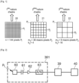
- a macro-pixel designates a group of several unit pixels. If we apply this definition to the example of figure 1 , the first configuration of optical sensors has pixels P 1 (unit) while the second configuration and the third configuration of optical sensors have macro-pixels P 2 and P 3 respectively.
- the signals delivered by the unit pixels of a macro-pixel are considered as a single global signal to be processed. This signal is representative of the radiation captured at the level of the entire macro -pixel.
- the magnitude considered is advantageously an apparent magnitude or a surface brightness, well known to those skilled in the art, the latter being more relevant for extended celestial objects such as galaxies or nebulae.
- the present invention is not limited to defining two natures of stars, for example by distinguishing between small, highly luminous stars and large, weakly luminous stars.
- the invention can define much more than two natures of stars - corresponding to as many configurations of optical sensors - to categorize the stars observed according to their size and/or their luminosity.
- the fact of using at least two configurations of optical sensors - from unit pixels and groupings of said unit pixels - makes it possible to avoid the use of different optics, to observe luminous or dim stars.
- the invention makes it possible to alternately select one or other of the sensor configurations, depending on the nature of the star that the user wishes to observe.
- computing processes correspond to the actions or results obtained by the execution of instructions from different computer applications. Also, it must also be understood in the sense of the invention that “ a computer process is adapted to do something ” means “the instructions of a computer application executed by a processing unit do something ”.
- the apparatus 30 which is the subject of the invention is used for the observation of both large stars and small stars.
- These stars or objects or celestial bodies can be planets, stars, nebulae, galaxies, etc. It is preferably a telescope (or astronomical telescope), but the device can also be in the form of a photographic device or a video camera.
- the rest of the description only refers to a telescope adapted for the observation of stars of different nature, in particular stars of small size 50 relatively luminous (e.g. planets , moon) and large 51 darker stars (e.g. nebulae, galaxies).
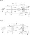
- the telescope 30 notably comprises a hollow body 302 inside which, in use, light rays 34 coming from the observed star 50, 51 penetrate.
- the hollow body 302 has a first end 300 through which the light rays 34 penetrate and a second end 301 opposite said first end.
- the hollow body 302 is preferably in the form of a hollow tube of circular section, but could be a tube of oval, square, octagonal or other section. It is specified that the hollow body 302 is not necessarily tubular in shape, but can be conical in shape, or formed of portions of tubes or cones for example.
- the hollow body 302 can be made of plastic material, composite material, etc. As an example, its length is between 200 mm and 400 mm, its diameter is between 50 mm and 500 mm and its thickness is between 1 mm and 10 mm.
- An optical system 31, 382, 383 is arranged in the hollow body 302 having an optical axis 32.
- the optical system is configured so that the light rays 34 form, in a focal plane 33, an image of the star 50, 51 observed.
- the telescope has an optical axis 32.
- optical axis means the line which passes through the center of each optical element of the optical system 31, 382, 383.
- the optical axis 32 is a rectilinear axis. confused with the axis of symmetry of the telescope 30.
- Other configurations are however possible, in which the optical axis 32 is not rectilinear and is broken down into a main optical axis (confused with the axis of symmetry) and by an axis secondary optics.
- the telescope has an image focus 330 at the intersection between the optical axis 32 and the light rays 34.
- the image focus 330 is in the focal plane 33.
- a matrix of optical sensors 361 is arranged in the image focus 330 to acquire the image of the star 50, 51 observed, formed in said image focus 330.
- the matrix 361 is fixed on a support 35 installed in the hollow body 302, near the second end 301.
- the support 35 can optionally be mobile.
- the support 35 is for example made of steel, carbon, or a plastic material, so that its design is simple, inexpensive and durable over time.
- the support 35 is preferably circular in shape, but can also be square, octagonal, oval, etc.
- the shape and dimensions of the support 35 are adapted to the dimensions of the matrix 361. For example, its surface is between 2 cm 2 and 8 cm 2 . These reduced dimensions make it possible to use a minimum of space in the device 30.
- the optical system comprises a primary mirror 382 disposed in the hollow body 302, on the side of the second end 301.
- This primary mirror 382 reflects and converges the light rays 34 towards the support 35 placed in the image focus 330.
- the support 35 on which the matrix 361 is fixed is preferably arranged in the first third of the hollow body 302, on the side of the first end 300 so as not to interfere with the tangent light rays reflected by the primary mirror 382.
- Such an optical system makes it possible to reduce the length of the hollow body 302, while keeping the same focal length of a telescope comprising only a primary mirror 382 (as illustrated in the Figure 10 For example).
- the primary mirror 382 and the secondary mirror 383 are on the optical axis 32 which coincides with the axis of symmetry of said hollow body 302. These mirrors are pure reflection.
- the primary mirror 382 is preferably a concave parabolic mirror having a low focal ratio (preferably less than 5). This type of mirror makes it possible to overcome spherical aberrations.
- the diameter of the primary mirror 382 corresponds substantially to the internal diameter of the hollow body 302. This primary mirror 382 has at its center an opening 3820 coaxial with the optical axis 32.
- the primary mirror 382 is arranged near the second end 301 of the body hollow 302.
- the secondary mirror 34 is positioned in the hollow body 302, at the level of the first end 300. The installation of the secondary mirror 383 inside the hollow body 302 makes it possible to preserve its physical integrity during handling and handling the telescope 30.
- the secondary mirror 383 is adapted to bring the focal plane 33 behind the primary mirror 382, the reflected light rays passing through the opening 3820.
- This design makes it possible to reduce the focal length and the length of the hollow body 302 and, in fact, to reduce the focal ratio while retaining a primary mirror 382 having a relatively large diameter.
- the telescope 30 is therefore particularly light and compact.
- the secondary mirror 383 can be concave or convex.
- a plane mirror is preferably used. Using a plane mirror offers several advantages. It makes it possible to bring back by symmetry, the focal plane 33 behind the primary mirror 382 and, therefore, the focal length of the optical system. It is also a mirror whose design is simple and inexpensive. The overall cost of the telescope 30 is therefore reduced.
- a plane mirror 383 with the primary mirror 382 is simpler to achieve, which limits assembly time and labor costs.
- the use of a plane mirror also makes it possible to use a secondary mirror whose diameter is significantly less than that of the primary mirror 382, so that said primary mirror obscures little of the light rays 34 penetrating into the hollow body 32.
- the secondary mirror 383 has a diameter equal to half the diameter of the primary mirror 382.
- the diameter of the secondary mirror 383 is between 25 mm and 250 mm for a primary mirror 382 having a diameter between 50 mm and 500 mm.
- the matrix 361 is arranged in the image focus 330, so that it does not interfere with the light rays 34 reflected by the primary mirror 382 and nor with the light rays reflected by the secondary mirror 383.
- the collected light is thus optimized by the matrix 361 and we minimize the loss of resolution due to the presence of the secondary mirror 383.
- access to the matrix 361 is easier so that its installation and/or replacement are faster and easier, without having to manipulate and/or disrupt the system optics 382, 383.
- the matrix 361 is that of a mobile user terminal , preferably a smart phone (smartphone) or a tablet, removably fixed on the hollow body 302, at the level of the second end 301.
- each matrix 361 of presenting a plurality of configurations of optical sensors makes it possible to obtain , in combination, with the fact for each matrix 361 of presenting a plurality of configurations of optical sensors, a wider range resolution so that not only can the user observe an even larger category of stars , but also to refine the resolution according to the nature of the star observed.
- a plurality of matrices are used, they advantageously have different sizes. Indeed, the size of a matrix influences the field of view.
- each of these matrices can be characterized by a matrix size, a pixel size, and a number of pixels that is specific to them.
- the matrix 361 comprises different configurations of optical sensors 20, 21, 22 so as to be adapted to the observation of stars 50, 51 of different nature.
- these different configurations 20, 21, 22 of optical sensors refer to a grouping of different pixels, conventionally from a size of unit pixels P 1 to a size of macro-pixels each formed by a grouping of a certain number of these unit pixels.
- Each configuration of pixels 20, 21, 22 is adapted to a type of star to be observed.
- the size pixels and macro-pixels and their number influence the resolution and the sensitivity of the method and the image acquisition device of a star.
- the size of the matrix 361 which determines the field of view. Indeed, the larger the 361 matrix, the wider the portion of sky observed. It will therefore be possible to observe extended stars such as nebulae or deep sky stars. Conversely, with a smaller 361 matrix , the portion of sky observed will be further reduced. The field of view being restricted, we will be able to observe smaller stars such as planets.
- the aim of the present invention is to cover with a single and unique matrix 361 all the possibilities for observing stars, from bright stars to faint stars.
- the principle of a plurality of configurations 20, 21, 22 of optical sensors can be combined with the use of a plurality of matrices 361 provided that at least one matrix 361 has this plurality of configurations 20 , 21, 22 of optical sensors.
- the size of the matrix 361 (single) is between 1 square millimeter (mm 2 ) and 1000 mm 2 , preferably between 5 mm 2 and 50 mm 2 .
- the optical resolution of the telescope 30 is generally defined by the dimension of the mirror or the lens of the optical system 31.
- the size of the pixels of the matrix 361 of sensors determines the digital resolution of the observed image and indirectly the possibility of zooming. Indeed, as the pixel size decreases, the digital resolution increases. And by increasing the digital resolution, it is possible to achieve a good quality enlargement of part of the observed image. Conversely , if the digital resolution is low, the enlargement will be of lower quality.
- the resolution of the digital telescope is determined by the least resolved element between the optics and the sensor array. It is therefore not advantageous to use a pixel size smaller than the optical resolution of the telescope 30.
- Pixel size also affects light sensitivity. Small pixels are not very sensitive. Conversely, larger pixels are more sensitive. If the user observes a small star 50, such as a planet for example which is very luminous, it is not necessary to have a strong sensitivity. The observation of small stars 50 can therefore be done with small pixels having low sensitivity so that we concentrate on the digital resolution which makes it possible to observe details of the surface of the planet (e.g. : storms, craters, etc.). Conversely, if the user observes a large star 51, such as a nebula for example which is not very luminous, it is advantageous to have high sensitivity to light. These stars being large, it is not necessary to have very high resolution to observe details (gas clouds, galaxy arms).
- the matrix 361 is preferably a CCD (for the English acronym Charged Coupled Device) or CMOS (for the English acronym Complementary Metal Oxide Semiconductor) sensor comprising an arrangement of pixels (making it possible to generate images, preferably color images).
- CCD Charged Coupled Device
- CMOS Complementary Metal Oxide Semiconductor
- This type of matrix has reduced dimensions, which allows it to be easily installed in a telescope or the like.
- the matrix 361 presents a plurality n of identical or similar pixels P 1 , for example arranged in rows and columns, where n is a non-zero natural integer whose value depends on the size of said matrix.
- the number “n” is between 10 5 (one hundred thousand pixels) and 10 9 (one billion pixels), preferably between 10 6 (one million) and 10 8 (one hundred million).
- the size of the pixels P 1 or "unit" pixels, is between 0.1 ⁇ m and 20 ⁇ m, preferably between 0.5 ⁇ m and 10 ⁇ m.
- size in relation to a pixel, we mean the fact that one side of a pixel - classically square or polygonal - has the defined size.
- Each unit pixel P 1 is a photosensitive component adapted to convert, by photoelectric effect, electromagnetic radiation into an electrical signal.
- FIG 2 illustrates schematically, and by way of explanatory example only, an arrangement of components of a unit pixel P 1 .
- This comprises a photoelectric conversion element 60, for example a photodiode, capable of generating a photocurrent representative of a received light intensity. It further comprises a capacitive storage element 61 integrating the photocurrent generated by the photoelectric conversion element 60.
- the measurement of the level of illumination received by a pixel P 1 is carried out by measuring a voltage variation across the capacitive element 61 between the start and the end of an integration period.
- the resulting signal then undergoes amplification (for example by means of an operational amplifier 62) and digitization (for example by means of an analog/digital converter 63) to be converted into a digital signal.
- amplification for example by means of an operational amplifier 62
- digitization for example by means of an analog/digital converter 63
- These different digital signals are then transmitted to an electronic processing unit 39 adapted to generate a digital representation of the image of the star 50, 51 formed in the image focus 330.
- connection between the matrix 361 and the unit 39 can be made wired or wirelessly, for example according to a proximity communication protocol, such as, by way of non-limiting examples, the Bluetooth® , Wifi® , Zigbee® .
- the matrix 361 is connected to the unit 39 and the data from the matrix are observed on a screen 40.
- the unit 39 comprises a calculator in the form of a processor, microprocessor or CPU (for Central Processing Unit), a memory and generally the computer resources making it possible to ensure the processing of the signals received from the matrix 361 for the formation of a digital representation of the image of the star 50, 51 acquired by said matrix.
- These components are preferably mounted on an electronic card which makes it possible to group all the electronic components of unit 39 in a single place, and on a single support. This design makes it possible to minimize the number of electronic cards integrated into the telescope 30, and reduce the number of cabling.
- the manufacture of unit 39, its installation in the telescope 30 and, where applicable, its maintenance are greatly facilitated.
- the digital representation generated by the unit 39 is displayed on a screen 40.
- the screen 40 can be fixed on the electronic card, so that the unit 39 and said screen form a single piece assembly which is easily manipulated.
- a flat screen is advantageously used, for example a polychrome liquid crystal screen LCD (for Liquid Crystal Display) or OLED (for Organic Light-Emitting Diode).
- the screen 40 is separated from the unit 39 and the electronic card. It is physically distant from the hollow body 302.
- the screen 40 can be that of a mobile terminal of the user, for example the screen of a Smartphone (smart phone) or a tablet tactile.
- the connection between the unit 39 and the screen 40 can be made via a wired connection (for example by means of a USB cable) or via a wireless connection, for example according to a proximity communication protocol, such as 'by way of non-limiting example, the Bluetooth, Wifi, ZigBee protocol .
- This embodiment makes it possible to increase the compactness of the telescope 30 since the bulk of the screen 40 is not taken into account.
- the matrix 361 presents several configurations of optical sensors, and for example three configurations referenced 20, 21 and 22.
- the first configuration 20 presents the plurality n of unit pixels P 1 .
- the number n is equal to 144 pixels and that the size of each unit pixel P 1 is 10 ⁇ m.
- this example includes numerical values - size of each pixel and number of pixels - but these have no limiting character in the context of the present invention.
- each unit pixel P 1 provides a digital signal, the processing unit 39 receiving and processing each of these signals.
- each unit pixel P 1 delivers a signal which is proportional to the number of photons incident on said unit pixel.
- the signals delivered by the unit pixels P 1 are considered as singular signals to be processed by the processing unit 39.
- the Figure 3 illustrates this case. Eight unit pixels P 1 are represented, each of these pixels transmitting a digital signal to the processing unit 39.
- This first configuration 20 is intended for the observation of stars of a first nature. Considering that the size of the matrix 361 is unchanged, each configuration 20, 21 and 22 has the same overall size, identical to that of the matrix 361. Thus, compared to the other configurations of optical sensors 21 and 22, the first configuration of sensors optical 20 has a large number n of pixels P 1 , each of a small size, in this case equal to the unit size of the pixels; the term “unitary” being used here to designate the pixels of smaller size in a matrix 361.
- the first configuration of optical sensors 20 is dedicated to luminous stars, for example having an apparent magnitude less than 0, so that with this first configuration 20, we must have good to very good resolution, but the brightness does not need to be increased significantly.
- the second configuration of optical sensors 21 presents a plurality m 2 of macro-pixels P 2 formed by groupings of unit pixels P 1 .
- k 2 is less than or equal to n/16.
- Each macro-pixel P 2 is thus formed by a grouping of 4 unit pixels P 1 . More generally, each macro-pixel P 2 is formed by a grouping of k 2 unit pixels P 1 .
- the size of a macro- pixel P 2 is then k 2 times the size of a unit pixel P 1 .
- the unit pixels P 1 can be grouped in the form of rows and columns, which rows and columns may or may not have the same number of unit pixels P 1 .
- a macro-pixel P 2 can thus have a square or rectangular shape.
- a macro-pixel P 2 can however have another geometric shape and the macro-pixels P 2 do not have not necessarily the same shape within the second configuration 21 as illustrated in the figure 5 .
- the macro-pixels P 2 are formed by groupings of unit pixels P 1 arranged in the form of rows and columns, which rows and columns have the same number of unit pixels.
- k 2 p 2 2 .
- Such a grouping of unit pixels makes it possible to have macropixels of square or substantially square shape, making it possible to generate a homogeneous digital representation of the captured image.
- the signals delivered by the unit pixels P 1 of a macro-pixel P 2 are considered as a single global signal to be processed by the processing unit 39. This signal is proportional to the number of photons incident on the entire group of unit pixels P 1 forming the macro-pixel P 2 .
- THE figures 4a , 4b And 4c illustrate different ways of processing the signals in the case of the second configuration 21.
- Four macro-pixels P 2 are represented, each of these macro-pixels being formed by a group of two unit pixels P 1 .
- the signals of two unit pixels P 1 of a macro- pixel P 2 are summed after digitization.
- This operation can for example be carried out by means of a summing circuit CS integrated in the matrix 361 and activated by the processing unit 39 when the second configuration 21 is selected.
- the summing circuit CS receives as input the output signals from the analog/digital converters 63.
- the signals of the unit pixels P 1 of a macro- pixel P 2 are summed before digitization and after amplification (at the output of the analog/digital converter 63).
- the summing circuit CS receives as input the output signals of the amplifiers 62.
- the output of the summing circuit CS is connected to one of the analog/digital converters 63 of the group of unit pixels P 1 of the macro-pixel P 2 .
- the reading noise is reduced to the extent that the signal delivered by a macro-pixel P 2 only undergoes a single digitization before being transmitted to the processing unit 39.
- the number of data transmitted to the processing unit 39 from the matrix 391 is divided by a factor of 2 on the figures 4a And 4b and more generally by a factor k 2 mentioned above.
- the refresh rate or frame rate of the matrix 361 can then be multiplied by k 2 .
- the processing unit 39 receives the signals emitted by all of the unit pixels P 1 of the matrix 361.
- the signals associated with the unit pixels P 1 constituting a macro-pixel P 2 are summed in the processing unit 39 , for example by means of a layer software.
- This solution has the advantage of being able to use a 361 matrix that is less complex than those of figures 4a And 4b (because it does not include the summing stage ) and therefore less expensive.
- the second configuration 21 is defined to acquire the image of a second type of star of lower luminosity than a first type star.
- these second nature stars have an apparent magnitude between 0 and 6.
- the use of macro -pixels P 2 of larger size than the unit pixels P 1 make it possible to capture greater radiation and therefore benefit from greater luminosity.
- grouping k 2 pixels P 1 into a macro-pixel P 2 makes it possible to gain brightness. In return, we lose resolution.
- the size of the star can also be a criterion for selecting the second configuration of optical sensors 21.
- the embodiments of the figures 4a And 4b make it possible to increase the refresh rate of the matrix 361. This can be particularly advantageous when the image of the star observed is acquired in video mode and we wish to improve the fluidity of the observed video.
- first configuration 20 for acquisition in the form of photographic shots
- second configuration 21 for visualization in mode video.
- second configuration 21 for viewing in video mode.
- the third configuration of optical sensors 22 is similar to the second configuration 21 in the sense that it presents a plurality m 3 of macro-pixels P 3 formed by groupings of unit pixels P 1 .
- Each macro-pixel P 3 is , however, formed by the grouping of a larger number of unit pixels P 1 .
- Each macro-pixel P 3 is thus formed by a grouping of 16 unit pixels P 1 .
- each macro-pixel P 3 is formed by a grouping of k 3 unit pixels P 1 .
- the size of a macro- pixel P 3 is then k 3 times the size of a unit pixel P 1 .
- the signals delivered by the unit pixels P 1 of a macro-pixel P 3 of the third configuration 22 are considered as a single global signal to be processed by the processing unit 39. Which signal is proportional to the number of photons incident on the entire group of unit pixels P 1 forming the macro-pixel P 3 .
- THE figures 6a , 6b And 6c illustrate different ways of processing the signals in the case of the third configuration 22.
- Two macro-pixels P 2 are represented, each of these macro-pixels being formed by a group of four unit pixels P 1 .
- the modes of realization of figures 6a , 6b And 6c are respectively similar to those of figures 4a , 4b And 4c , except that it is now the signals of four unit pixels P 1 of a macro -pixel P 3 which are summed.
- the third configuration 22 is defined to acquire the image of a third nature of star , in particular a star of lower brightness than a second nature star.
- these third nature stars have an apparent magnitude greater than 6.
- the third configuration of optical sensors 22 can also be selected in order to further increase the refresh rate of the matrix 361 during of a visualization of a star in video mode.
- the invention is not limited to the use of three configurations 20, 21 and 22 and can provide a larger number of optical sensor configurations or, on the contrary, only two.
- the first configuration 20 can for example be provided for stars of apparent magnitude less than or equal to 6 and the second configuration for stars of apparent magnitude greater than 6.
- the matrix 361 has only one pixel size.
- the matrix 361 presents only unit pixels P 1 when the first configuration 20 is selected, or only macro-pixels P 2 when the second configuration 21 is selected, or only macro-pixels P 3 when the third configuration 22 is selected.
- the selection is made manually by the user.
- the telescope 30 has buttons pushers or the like 70, 71, 72 to modify the configuration 20, 21, 22 of optical sensors and move from one to the other successively or directly.
- the activation of the first button 70, the second button 71 or the third button 72 respectively results in the selection of the first configuration 20, the second configuration 21, or the third configuration 22, by the processing unit 39.
- these buttons 70, 71, 72 can be labeled with the nature of the stars.
- the first button 70 can be associated with the indications " planets/bright stars", the second button 71 with " deep sky stars” and the third button 72 with "galaxies /nebula".
- Control of the configuration of optical sensors 20, 21 or 22 can also be done by transmitting to the processing unit 39, control instructions issued from a Smartphone (smart phone) of the user. These instructions are for example issued following the activation of one or more dedicated keys displayed on a graphical interface of the Smartphone. These keys can be labeled in the same way as buttons 70, 71, 72 described previously.
- the Smartphone is adapted to communicate with the processing unit 39 and transmit control instructions to it, for example via a Wifi® or Bluetooth® connection.
- the processing unit 39 controls the selection of the configuration of optical sensors 20, 21 or 22.
- the selection of a configuration 20, 21 or 22 is done automatically.
- the selected configuration 20, 21 or 22 is then activated without the user having to intervene.
- Different cases of automatic activation may occur. The cases presented below are not limiting to the invention, other uses may be envisaged.
- the user points his telescope 30 towards an observation scene corresponding to a portion of the celestial vault.
- the processing unit 39 is connected to a database in which the main stars known to those skilled in the art are recorded.
- This database can be integrated into the telescope 30.
- the database is remote from the telescope 30, for example hosted in a remote server to which the processing unit 39 is connected.
- the connection of the unit 39 to the database can in this case be carried out through an internal type communication network, 3G, 4G, 5G, etc.
- the processing unit 39 records time data t corresponding to the acquisition period, that is to say at the time when the user selects the record in the database.
- the processing unit 39 searches the database for the celestial coordinates of the star at time t. Thanks to a correlation of the terrestrial location data of the telescope 30, for example by means of a GPS (for “Global Positioning System” or navigation assistant in French) and the orientation data of said telescope, for example by means of an accelerometer, the processing unit 39 activates an on-board motorized device making it possible to automatically orient said telescope towards the location of the selected star 50, 51.
- the processing unit 39 controls or in parallel the selection of the configuration of optical sensors 20, 21 or 22 associated with the selected recording and which is best suited for the observation of this star. The image can then be acquired optimally.
- the user observes a star and acquires its image with a configuration of optical sensors 20, 21 or 22 optimal for observing this star.
- Another star moves in the field of view (or observation scene).
- the user observes, for example, a small star 50 (a planet) with the first configuration 20 active and an asteroid passes into the field of view.
- the processing unit 39 executes a computer process configured to detect this passage of this other star in the observation scene. This process is for example based on motion detection. It may then be advantageous to zoom out to widen the observation scene and observe the asteroid for a longer time in video mode with an optimal refresh rate of the matrix 361.
- the second configuration 21 (or the third configuration 22) is then selected by the processing unit 39.
- This automatic change of configuration can also be carried out when the user initially observes a large star 51 (with the third configuration 22 active) and it is advantageous to zoom in to restrict the scene of observation (activation of the first or second configuration 20, 21).
- this analysis is carried out by executing a computer recognition process configured to detect at least one characteristic element, for example by implementing a thresholding analysis. If necessary, those skilled in the art may refer in particular to the patent documents FR3054897 and or US2019196173 for more details on such a computer recognition process.
- the processing unit 39 identifies, in the database , a star record associated with a characteristic element similar to that detected. As soon as a similar characteristic element is detected, the recording of the corresponding star is identified as well as the configuration of optical sensors 20, 21 or 22 associated with this recording. The processing unit 39 then selects the configuration 20, 21 or 22 associated with the recording and transmits a control or selection instruction to activate the corresponding configuration 20, 21 or 22.
- configuration 20, 21 or 22 having acquired the image is the correct one, it remains active. Conversely, if the configuration 20, 21 or 22 having acquired the image is not the correct one, then the processing unit 39 selects the correct configuration of optical sensors 20, 21 or 22. The image can then be acquired optimally.
- the acquired image includes several stars having different luminosities , several configurations can be selected simultaneously, each of these configurations being activated in a distinct zone of the matrix 361 where the image of the corresponding star is located.
- the acquired image includes several stars having different sizes, several configurations can be selected simultaneously, each of these configurations being activated in a distinct area of the matrix 361 where the image of the corresponding star is located.
- the analysis of the digital representation is carried out by executing a computer process making it possible to detect a movement of the observed star . If this star is luminous, the first configuration 20 could be selected by default. But if this star is moving (for example a comet), then the second configuration 21 or the third configuration 22 can be automatically selected so as to increase the refresh rate of the matrix 361 and acquire images of the star in mode video, as explained previously.
- the acquired image includes fixed stars and moving stars
- several configurations can be selected simultaneously, each of these configurations being activated in a distinct area of the matrix 361 where the image of the corresponding star is located.
- one or more characteristics and/or steps exposed only in one embodiment can be generalized to other embodiments.
- one or more characteristics and/or steps exposed only in one embodiment can be combined with one or more others characteristics and/or steps exposed only in another embodiment.
Landscapes
- Physics & Mathematics (AREA)
- General Physics & Mathematics (AREA)
- Optics & Photonics (AREA)
- Spectroscopy & Molecular Physics (AREA)
- Astronomy & Astrophysics (AREA)
- Engineering & Computer Science (AREA)
- Theoretical Computer Science (AREA)
- Photometry And Measurement Of Optical Pulse Characteristics (AREA)
- Solid State Image Pick-Up Elements (AREA)
- Telescopes (AREA)
- Studio Devices (AREA)
Claims (15)
- Verfahren zur Bilderfassung mindestens eines Gestirns, das die folgenden Schritte aufweist:- ein Gerät (30) zu verwenden, das einen Hohlkörper (302) aufweist, in dessen Inneres bei Benutzung Lichtstrahlen (34) eindringen, die von mindestens einem beobachteten Gestirn stammen, wobei das beobachtete Gestirn unter mindestens einem ersten Gestirn (50) einer ersten Beschaffenheit und einem zweiten Gestirn (51) einer zweiten Beschaffenheit ausgewählt wird, wobei die Beschaffenheit des ersten Gestirns (50) sich von der Beschaffenheit des zweiten Gestirns (51) unterscheidet,- ein optisches System (31, 382, 383) mit einer optischen Achse im Hohlkörper (302) anzuordnen, wobei das optische System (31, 382, 383) so konfiguriert ist, dass die Lichtstrahlen (34) in einem in einer Brennebene (33) befindlichen Bildbrennpunkt (330) ein Bild des beobachteten Gestirns formen,- eine Matrix (361) von optischen Sensoren im Bildbrennpunkt (330) anzuordnen, um das Bild des beobachteten Gestirns zu erfassen, wobei die Matrix eine Vielzahl n von Einzelpixeln P1 aufweist,dadurch gekennzeichnet, dass es ebenfalls die folgenden Schritte enthält:- eine erste Konfiguration (20) von optischen Sensoren der Matrix (361) zu definieren, um das Bild des ersten Gestirns (50) erster Beschaffenheit zu erfassen, wobei die erste Konfiguration die Vielzahl n von Einzelpixeln P1 aufweist, wobei n eine natürliche ganze Zahl ist,- mindestens eine zweite Konfiguration (21) von optischen Sensoren der Matrix (361) zu definieren, um das Bild des zweiten Gestirns (51) zweiter Beschaffenheit zu erfassen, wobei die zweite Konfiguration (21) eine Vielzahl m2 von Makropixeln P2 aufweist, die von Gruppierungen von Einzelpixeln P1 geformt werden, wobei m2 eine natürliche ganze Zahl ist,- eine der Konfigurationen (20, 21) von optischen Sensoren auszuwählen, um das im Bildbrennpunkt (330) geformte Bild des Gestirns zu erfassen, wobei die Auswahl der Konfiguration von optischen Sensoren abhängig von der Beschaffenheit des beobachteten Gestirns, entweder des ersten Gestirns (50) erster Beschaffenheit oder des zweiten Gestirns (51) zweiter Beschaffenheit, durchgeführt wird.
- Verfahren nach Anspruch 1, das darin besteht, die zweite Konfiguration (21) von optischen Sensoren gemäß der Formel m2=n/k2 zu definieren, mit k2 einer natürlichen ganzen Zahl größer als oder gleich 2.
- Verfahren nach einem der Ansprüche 1 oder 2, das darin besteht, die zweite Konfiguration (21) von optischen Sensoren gemäß der Formel m2=n/p2 2 zu definieren, mit p2 einer natürlichen ganzen Zahl größer als oder gleich 2.
- Verfahren nach einem der vorhergehenden Ansprüche, das die Schritte enthält, die darin bestehen:- ein Bild des beobachteten Gestirns mittels der Matrix (361) von optischen Sensoren zu erfassen und eine digitale Darstellung des Bilds zu erzeugen,- die digitale Darstellung zu analysieren, um einen Wert der Helligkeit des beobachteten Gestirns zu berechnen,und wobei die Auswahl der Konfiguration (20, 21) von optischen Sensoren abhängig vom Ergebnis eines Vergleichs dieses berechneten Werts mit einem oder mehreren vorab gespeicherten Schwellenwerten oder mit einem oder mehreren vorab gespeicherten Bereichen von Schwellengrößen automatisch durchgeführt wird.
- Verfahren nach einem der vorhergehenden Ansprüche, das die Schritte enthält, die darin bestehen:- ein Bild des beobachteten Gestirns mittels der Matrix (361) von optischen Sensoren zu erfassen und eine digitale Darstellung des Bilds zu erzeugen,- die digitale Darstellung zu analysieren, um einen Wert der Größe des beobachteten Gestirns zu berechnen,und wobei die Auswahl der Konfiguration (20, 21) von optischen Sensoren abhängig vom berechneten Wert der Helligkeit des beobachteten Gestirns automatisch durchgeführt wird, indem er mit einem oder mehreren vorab gespeicherten Schwellenwerten oder mit einem oder mehreren vorab gespeicherten Bereichen von Schwellengrößen verglichen wird.
- Verfahren nach einem der vorhergehenden Ansprüche, das die Schritte enthält, die darin bestehen:- ein Bild eines ersten Gestirns (50) erster Beschaffenheit und eines zweiten Gestirns (51) zweiter Beschaffenheit mittels der Matrix (361) von optischen Sensoren zu erfassen, wobei das Bild jedes Gestirns sich in einer separaten Zone der Matrix befindet,- eine digitale Darstellung des erfassten Bilds zu erzeugen,- die digitale Darstellung zu analysieren, um die erste Beschaffenheit des ersten Gestirns und die zweite Beschaffenheit des zweiten Gestirns zu bestimmen,- die erste Konfiguration (20) von optischen Sensoren in der Zone der Matrix (361), in der sich das Bild des ersten Gestirns erster Beschaffenheit befindet, und die zweite Konfiguration (21) von optischen Sensoren in der Zone der Matrix, in der sich das Bild des zweiten Gestirns zweiter Beschaffenheit befindet, automatisch auszuwählen, wobei die Konfigurationen gleichzeitig ausgewählt werden.
- Verfahren nach einem der vorhergehenden Ansprüche, das die Schritte enthält, die darin bestehen:- in einer Datenbank Gestirn-Datensätze (50, 51) zu speichern, wobei jeder Datensatz einer Konfiguration (20, 21) von optischen Sensoren sowie Echtzeit-Lokalisierungsdaten des Gestirns und/oder mindestens einem charakteristischen Element des Gestirns (50, 51) zugeordnet ist,- in der Datenbank einen Gestirn-Datensatz (50, 51) auszuwählen,- die Konfiguration (20, 21) von optischen Sensoren auszuwählen, die dem ausgewählten Gestirn-Datensatz (50, 51) zugeordnet ist,- abhängig von den dem ausgewählten Datensatz zugeordneten Lokalisierungsdaten das Gerät (30) automatisch zu der Lokalisierung des Gestirns (50, 51) auszurichten.
- Verfahren nach einem der vorhergehenden Ansprüche, das die Schritte enthält, die darin bestehen:- ein Bild eines in einer Beobachtungsszene entsprechend einem Teil des Himmelsgewölbes beobachteten Gestirns zu erfassen, wobei die Erfassung mittels einer der Konfigurationen (20, 21) von optischen Sensoren durchgeführt wird, die abhängig von der Beschaffenheit des Gestirns (50, 51) ausgewählt wird,- einen Informatikprozess auszuführen, der konfiguriert ist, die Verschiebung eines anderen Gestirns in der Beobachtungsszene zu erkennen,- die andere Konfiguration (20, 21) von optischen Sensoren entsprechend dem anderen Gestirn auszuwählen.
- Verfahren nach einem der vorhergehenden Ansprüche, das die Schritte enthält, die darin bestehen:- in einer Datenbank Gestirn-Datensätze (50, 51) zu speichern, wobei jeder Datensatz einer der Konfigurationen (20, 21) von optischen Sensoren und mindestens einem charakteristischen Element des Gestirns (50, 51) zugeordnet ist,- ein Bild eines Gestirns (50, 51) zu erfassen, wobei die Erfassung mittels einer der Konfigurationen (20, 21) von optischen Sensoren durchgeführt wird,- einen Erkennungs-Informatikprozess auszuführen, der konfiguriert ist, im erfassten Bild mindestens ein charakteristisches Element des Gestirns (50, 51) zu erkennen,- in der Datenbank einen Gestirn-Datensatz (50, 51) zu identifizieren, der einem charakteristischen Element gleich dem erkannten zugeordnet ist,- die Konfiguration (20, 21) von optischen Sensoren auszuwählen, die dem identifizierten Datensatz zugeordnet ist,- wenn die Konfiguration (20, 21) von optischen Sensoren, die das Bild erfasst hat, nicht der ausgewählten Konfiguration (20, 21) von optischen Sensoren entspricht, diese letztere Konfiguration (20, 21) von Sensoren auszuwählen.
- Gerät (30) zur Bilderfassung eines Gestirns (50, 51), das aufweist:- einen Hohlkörper (302), in dessen Inneres bei Benutzung Lichtstrahlen (34) eindringen, die von mindestens einem beobachteten Gestirn stammen, wobei das beobachtete Gestirn unter mindestens einem ersten Gestirn (50) einer ersten Beschaffenheit und einem zweiten Gestirn (51) einer zweiten Beschaffenheit ausgewählt wird, wobei die Beschaffenheit des ersten Gestirns (50) sich von der Beschaffenheit des zweiten Gestirns (51) unterscheidet,- ein optisches System (31, 382, 383), das im Hohlkörper (302) angeordnet ist und eine optische Achse aufweist, wobei das System so konfiguriert ist, dass die Lichtstrahlen (34) in einem in einer Brennebene (33) befindlichen Bildbrennpunkt (330) ein Bild des beobachteten Gestirns formen,- eine im Bildbrennpunkt (330) angeordnete Matrix (361) von optischen Sensoren, die aus einer Vielzahl n von Einzelpixeln P1 besteht,dadurch gekennzeichnet, dass das Gerät (30) aufweist:- eine erste Konfiguration (20) von optischen Sensoren der Matrix (361), um das Bild des ersten Gestirns (50) erster Beschaffenheit zu erfassen, wobei die erste Konfiguration die Vielzahl n von Einzelpixeln P1 aufweist, wobei n eine natürliche ganze Zahl ist,- eine zweite Konfiguration (21) von optischen Sensoren der Matrix (361), um das Bild des zweiten Gestirns (51) zweiter Beschaffenheit zu erfassen, wobei die zweite Konfiguration (21) eine Vielzahl m2 von Makropixeln P2 aufweist, die von Gruppierungen von Einzelpixeln P1 geformt werden, wobei m2 eine natürliche ganze Zahl ist,- eine Verarbeitungseinheit (39), die geeignet ist, eine der Konfigurationen (20, 21) von optischen Sensoren auszuwählen, um das im Bildbrennpunkt (330) geformte Bild des Gestirns zu erfassen, wobei die Auswahl der Konfiguration (20, 21) von optischen Sensoren abhängig von der Beschaffenheit des beobachteten Gestirns, entweder des ersten Gestirns (50) erster Beschaffenheit oder des zweiten Gestirns (51) zweiter Beschaffenheit, durchgeführt wird.
- Gerät nach Anspruch 10, wobei die Makropixel P2 innerhalb der zweiten Konfiguration (21) von optischen Sensoren die gleiche Form haben.
- Gerät nach Anspruch 10, wobei die Makropixel P2 innerhalb der zweiten Konfiguration (21) von optischen Sensoren unterschiedliche Formen haben.
- Gerät nach einem der Ansprüche 10 bis 12, wobei die Verarbeitungseinheit (39) geeignet ist, gleichzeitig die erste Konfiguration (20) von optischen Sensoren in einer Zone der Matrix (361), in der sich das Bild eines ersten Gestirns erster Beschaffenheit befindet, und die zweite Konfiguration (21) von optischen Sensoren in einer Zone der Matrix auszuwählen, in der sich das Bild eines zweiten Gestirns zweiter Beschaffenheit befindet.
- Gerät nach einem der Ansprüche 10 bis 13, wobei:- jedes Einzelpixel P1 ein für eine empfangene Lichtstärke repräsentatives Signal liefert,- die Matrix (361) einen Summierschaltkreis (CS) umfasst, der geeignet ist, die von den Einzelpixeln P1 eines Makropixels P2 erzeugten Signale zu summieren, so dass die von den Einzelpixeln eines Makropixels P2 gelieferten Signale als ein einziges globales Signal angesehen werden, das von der Verarbeitungseinheit (39) zu verarbeiten ist.
- Gerät (30) nach einem der Ansprüche 10 bis 14, das in Form eines Teleskops vorliegt.
Applications Claiming Priority (1)
| Application Number | Priority Date | Filing Date | Title |
|---|---|---|---|
| FR2108394A FR3125894B1 (fr) | 2021-08-02 | 2021-08-02 | Procédé d’acquisition d’image d’au moins un astre et appareil pour la mise en œuvre du procédé |
Publications (3)
| Publication Number | Publication Date |
|---|---|
| EP4130867A1 EP4130867A1 (de) | 2023-02-08 |
| EP4130867B1 true EP4130867B1 (de) | 2024-04-17 |
| EP4130867C0 EP4130867C0 (de) | 2024-04-17 |
Family
ID=77999143
Family Applications (1)
| Application Number | Title | Priority Date | Filing Date |
|---|---|---|---|
| EP22188139.4A Active EP4130867B1 (de) | 2021-08-02 | 2022-08-01 | Verfahren zur erfassung eines bildes von mindestens einem stern und gerät zur durchführung des verfahrens |
Country Status (3)
| Country | Link |
|---|---|
| US (1) | US12461352B2 (de) |
| EP (1) | EP4130867B1 (de) |
| FR (1) | FR3125894B1 (de) |
Families Citing this family (1)
| Publication number | Priority date | Publication date | Assignee | Title |
|---|---|---|---|---|
| FR3125894B1 (fr) * | 2021-08-02 | 2023-07-28 | Unistellar | Procédé d’acquisition d’image d’au moins un astre et appareil pour la mise en œuvre du procédé |
Family Cites Families (10)
| Publication number | Priority date | Publication date | Assignee | Title |
|---|---|---|---|---|
| AU7118896A (en) * | 1995-09-28 | 1997-04-17 | Lockheed Martin Corporation | Techniques for optimizing an autonomous star tracker |
| US6118579A (en) * | 1998-04-04 | 2000-09-12 | Endemann; Thomas R. | Planetary astrographic telescope |
| US6765719B2 (en) * | 2002-05-21 | 2004-07-20 | The Boeing Company | Multiple field of view telescope |
| US9200966B2 (en) | 2013-07-24 | 2015-12-01 | Raytheon Company | Dual field of view telescope |
| RU2574522C9 (ru) * | 2014-10-17 | 2016-06-10 | Открытое акционерное общество "Красногорский завод им. С.А. Зверева" | Способ регистрации малоконтрастных точечных объектов |
| WO2017012986A1 (en) * | 2015-07-17 | 2017-01-26 | Trinamix Gmbh | Detector for optically detecting at least one object |
| FR3054897B1 (fr) * | 2016-08-05 | 2019-05-31 | Unistellar | Procede d'elaboration d'une image numerique, produit programme d'ordinateur et systeme optique associes |
| FR3101443B1 (fr) * | 2019-09-26 | 2021-10-08 | Unistellar | Télescope équipé d’un dispositif de réglage de l’inclinaison et de la position d’un miroir |
| FR3108180A1 (fr) * | 2020-03-13 | 2021-09-17 | Unistellar | Procédé d’acquisition d’image d’un astre et appareil pour la mise en œuvre du procédé |
| FR3125894B1 (fr) * | 2021-08-02 | 2023-07-28 | Unistellar | Procédé d’acquisition d’image d’au moins un astre et appareil pour la mise en œuvre du procédé |
-
2021
- 2021-08-02 FR FR2108394A patent/FR3125894B1/fr active Active
-
2022
- 2022-08-01 US US17/878,145 patent/US12461352B2/en active Active
- 2022-08-01 EP EP22188139.4A patent/EP4130867B1/de active Active
Also Published As
| Publication number | Publication date |
|---|---|
| FR3125894A1 (fr) | 2023-02-03 |
| US20230049756A1 (en) | 2023-02-16 |
| US12461352B2 (en) | 2025-11-04 |
| EP4130867A1 (de) | 2023-02-08 |
| FR3125894B1 (fr) | 2023-07-28 |
| EP4130867C0 (de) | 2024-04-17 |
Similar Documents
| Publication | Publication Date | Title |
|---|---|---|
| EP1386480B1 (de) | Verfahren zur aufnahme und anzeige eines digitalen panoramabildes mit variabler auflösung | |
| EP3129813B1 (de) | Bildwechseldetektor mit geringer leistungsaufnahme | |
| EP3388975A1 (de) | Sensorvorrichtung zur aufnahme eines abdrucks eines körperteils | |
| WO2003010599A1 (fr) | Procede de capture d'une image panoramique au moyen d'un capteur d'image de forme rectangulaire | |
| Lin et al. | The prospects of finding tidal disruption events with 2.5-m Wide-Field Survey Telescope based on mock observations | |
| EP2593367B1 (de) | Raumüberwachungssystem zum überwachen des erdnahen raumes | |
| FR3064112A1 (fr) | Dispositif imageur optique | |
| EP3494430A1 (de) | Verfahren zur erzeugung eines digitalen bildes, zugehöriges computerprogrammprodukt und optisches system | |
| EP2810049B1 (de) | Optisches system zur messung von brdf, bsdf und bdtf | |
| Liu et al. | Future-proof imaging: computational imaging | |
| EP4130867B1 (de) | Verfahren zur erfassung eines bildes von mindestens einem stern und gerät zur durchführung des verfahrens | |
| EP4118479B1 (de) | Verfahren zur erfassung eines bildes eines himmelskörpers und gerät zur durchführung des verfahrens | |
| FR2800163A1 (fr) | Dispositif de mesure de la repartition spatiale de l'emission spectrale d'un objet | |
| Mackay et al. | High-resolution imaging in the visible from the ground without adaptive optics: new techniques and results | |
| CA2701151A1 (fr) | Systeme d'imagerie a modification de front d'onde et procede d'augmentation de la profondeur de champ d'un systeme d'imagerie | |
| Druart et al. | Compact infrared pinhole fisheye for wide field applications | |
| FR2972271A1 (fr) | Systeme d'imagerie a haute resolution | |
| de La Barrière et al. | Compact infrared cryogenic wafer-level camera: design and experimental validation | |
| WO2021048503A1 (fr) | Dispositif et procede pour la capture d'image d'un objet celeste observe | |
| WO2021156581A1 (fr) | Appareil pour l'observation d'un astre | |
| Arianpour et al. | Enhanced signal coupling in wide-field fiber-coupled imagers | |
| McGraw et al. | Lens systems for sky surveys and space surveillance | |
| WO2024046662A1 (fr) | Procédé de mise au point automatique dans un télescope | |
| WO2025133476A1 (fr) | Dispositif d'imagerie a forte distorsion geometrique | |
| FR2973892A1 (fr) | Systeme de conduite infrarouge stereoscopique a profondeur de champ augmentee |
Legal Events
| Date | Code | Title | Description |
|---|---|---|---|
| PUAI | Public reference made under article 153(3) epc to a published international application that has entered the european phase |
Free format text: ORIGINAL CODE: 0009012 |
|
| STAA | Information on the status of an ep patent application or granted ep patent |
Free format text: STATUS: THE APPLICATION HAS BEEN PUBLISHED |
|
| AK | Designated contracting states |
Kind code of ref document: A1 Designated state(s): AL AT BE BG CH CY CZ DE DK EE ES FI FR GB GR HR HU IE IS IT LI LT LU LV MC MK MT NL NO PL PT RO RS SE SI SK SM TR |
|
| STAA | Information on the status of an ep patent application or granted ep patent |
Free format text: STATUS: REQUEST FOR EXAMINATION WAS MADE |
|
| 17P | Request for examination filed |
Effective date: 20230711 |
|
| RBV | Designated contracting states (corrected) |
Designated state(s): AL AT BE BG CH CY CZ DE DK EE ES FI FR GB GR HR HU IE IS IT LI LT LU LV MC MK MT NL NO PL PT RO RS SE SI SK SM TR |
|
| GRAP | Despatch of communication of intention to grant a patent |
Free format text: ORIGINAL CODE: EPIDOSNIGR1 |
|
| STAA | Information on the status of an ep patent application or granted ep patent |
Free format text: STATUS: GRANT OF PATENT IS INTENDED |
|
| RIC1 | Information provided on ipc code assigned before grant |
Ipc: G06T 1/00 20060101ALI20231026BHEP Ipc: G02B 23/06 20060101ALI20231026BHEP Ipc: G02B 17/06 20060101ALI20231026BHEP Ipc: G03B 41/00 20210101ALI20231026BHEP Ipc: G03B 7/091 20210101AFI20231026BHEP |
|
| INTG | Intention to grant announced |
Effective date: 20231113 |
|
| GRAS | Grant fee paid |
Free format text: ORIGINAL CODE: EPIDOSNIGR3 |
|
| GRAA | (expected) grant |
Free format text: ORIGINAL CODE: 0009210 |
|
| STAA | Information on the status of an ep patent application or granted ep patent |
Free format text: STATUS: THE PATENT HAS BEEN GRANTED |
|
| AK | Designated contracting states |
Kind code of ref document: B1 Designated state(s): AL AT BE BG CH CY CZ DE DK EE ES FI FR GB GR HR HU IE IS IT LI LT LU LV MC MK MT NL NO PL PT RO RS SE SI SK SM TR |
|
| REG | Reference to a national code |
Ref country code: GB Ref legal event code: FG4D Free format text: NOT ENGLISH |
|
| REG | Reference to a national code |
Ref country code: CH Ref legal event code: EP |
|
| REG | Reference to a national code |
Ref country code: DE Ref legal event code: R096 Ref document number: 602022002898 Country of ref document: DE |
|
| REG | Reference to a national code |
Ref country code: IE Ref legal event code: FG4D Free format text: LANGUAGE OF EP DOCUMENT: FRENCH |
|
| U01 | Request for unitary effect filed |
Effective date: 20240418 |
|
| RAP4 | Party data changed (patent owner data changed or rights of a patent transferred) |
Owner name: UNISTELLAR |
|
| U07 | Unitary effect registered |
Designated state(s): AT BE BG DE DK EE FI FR IT LT LU LV MT NL PT SE SI Effective date: 20240517 |
|
| U20 | Renewal fee for the european patent with unitary effect paid |
Year of fee payment: 3 Effective date: 20240808 |
|
| PG25 | Lapsed in a contracting state [announced via postgrant information from national office to epo] |
Ref country code: IS Free format text: LAPSE BECAUSE OF FAILURE TO SUBMIT A TRANSLATION OF THE DESCRIPTION OR TO PAY THE FEE WITHIN THE PRESCRIBED TIME-LIMIT Effective date: 20240817 |
|
| PG25 | Lapsed in a contracting state [announced via postgrant information from national office to epo] |
Ref country code: HR Free format text: LAPSE BECAUSE OF FAILURE TO SUBMIT A TRANSLATION OF THE DESCRIPTION OR TO PAY THE FEE WITHIN THE PRESCRIBED TIME-LIMIT Effective date: 20240417 |
|
| PG25 | Lapsed in a contracting state [announced via postgrant information from national office to epo] |
Ref country code: GR Free format text: LAPSE BECAUSE OF FAILURE TO SUBMIT A TRANSLATION OF THE DESCRIPTION OR TO PAY THE FEE WITHIN THE PRESCRIBED TIME-LIMIT Effective date: 20240718 |
|
| PG25 | Lapsed in a contracting state [announced via postgrant information from national office to epo] |
Ref country code: ES Free format text: LAPSE BECAUSE OF FAILURE TO SUBMIT A TRANSLATION OF THE DESCRIPTION OR TO PAY THE FEE WITHIN THE PRESCRIBED TIME-LIMIT Effective date: 20240417 |
|
| PG25 | Lapsed in a contracting state [announced via postgrant information from national office to epo] |
Ref country code: PL Free format text: LAPSE BECAUSE OF FAILURE TO SUBMIT A TRANSLATION OF THE DESCRIPTION OR TO PAY THE FEE WITHIN THE PRESCRIBED TIME-LIMIT Effective date: 20240417 |
|
| PG25 | Lapsed in a contracting state [announced via postgrant information from national office to epo] |
Ref country code: PL Free format text: LAPSE BECAUSE OF FAILURE TO SUBMIT A TRANSLATION OF THE DESCRIPTION OR TO PAY THE FEE WITHIN THE PRESCRIBED TIME-LIMIT Effective date: 20240417 Ref country code: NO Free format text: LAPSE BECAUSE OF FAILURE TO SUBMIT A TRANSLATION OF THE DESCRIPTION OR TO PAY THE FEE WITHIN THE PRESCRIBED TIME-LIMIT Effective date: 20240717 Ref country code: IS Free format text: LAPSE BECAUSE OF FAILURE TO SUBMIT A TRANSLATION OF THE DESCRIPTION OR TO PAY THE FEE WITHIN THE PRESCRIBED TIME-LIMIT Effective date: 20240817 Ref country code: HR Free format text: LAPSE BECAUSE OF FAILURE TO SUBMIT A TRANSLATION OF THE DESCRIPTION OR TO PAY THE FEE WITHIN THE PRESCRIBED TIME-LIMIT Effective date: 20240417 Ref country code: GR Free format text: LAPSE BECAUSE OF FAILURE TO SUBMIT A TRANSLATION OF THE DESCRIPTION OR TO PAY THE FEE WITHIN THE PRESCRIBED TIME-LIMIT Effective date: 20240718 Ref country code: ES Free format text: LAPSE BECAUSE OF FAILURE TO SUBMIT A TRANSLATION OF THE DESCRIPTION OR TO PAY THE FEE WITHIN THE PRESCRIBED TIME-LIMIT Effective date: 20240417 Ref country code: RS Free format text: LAPSE BECAUSE OF FAILURE TO SUBMIT A TRANSLATION OF THE DESCRIPTION OR TO PAY THE FEE WITHIN THE PRESCRIBED TIME-LIMIT Effective date: 20240717 |
|
| REG | Reference to a national code |
Ref country code: DE Ref legal event code: R097 Ref document number: 602022002898 Country of ref document: DE |
|
| PG25 | Lapsed in a contracting state [announced via postgrant information from national office to epo] |
Ref country code: CZ Free format text: LAPSE BECAUSE OF FAILURE TO SUBMIT A TRANSLATION OF THE DESCRIPTION OR TO PAY THE FEE WITHIN THE PRESCRIBED TIME-LIMIT Effective date: 20240417 |
|
| PG25 | Lapsed in a contracting state [announced via postgrant information from national office to epo] |
Ref country code: SK Free format text: LAPSE BECAUSE OF FAILURE TO SUBMIT A TRANSLATION OF THE DESCRIPTION OR TO PAY THE FEE WITHIN THE PRESCRIBED TIME-LIMIT Effective date: 20240417 Ref country code: RO Free format text: LAPSE BECAUSE OF FAILURE TO SUBMIT A TRANSLATION OF THE DESCRIPTION OR TO PAY THE FEE WITHIN THE PRESCRIBED TIME-LIMIT Effective date: 20240417 |
|
| PG25 | Lapsed in a contracting state [announced via postgrant information from national office to epo] |
Ref country code: SM Free format text: LAPSE BECAUSE OF FAILURE TO SUBMIT A TRANSLATION OF THE DESCRIPTION OR TO PAY THE FEE WITHIN THE PRESCRIBED TIME-LIMIT Effective date: 20240417 |
|
| PG25 | Lapsed in a contracting state [announced via postgrant information from national office to epo] |
Ref country code: SM Free format text: LAPSE BECAUSE OF FAILURE TO SUBMIT A TRANSLATION OF THE DESCRIPTION OR TO PAY THE FEE WITHIN THE PRESCRIBED TIME-LIMIT Effective date: 20240417 Ref country code: SK Free format text: LAPSE BECAUSE OF FAILURE TO SUBMIT A TRANSLATION OF THE DESCRIPTION OR TO PAY THE FEE WITHIN THE PRESCRIBED TIME-LIMIT Effective date: 20240417 Ref country code: RO Free format text: LAPSE BECAUSE OF FAILURE TO SUBMIT A TRANSLATION OF THE DESCRIPTION OR TO PAY THE FEE WITHIN THE PRESCRIBED TIME-LIMIT Effective date: 20240417 Ref country code: CZ Free format text: LAPSE BECAUSE OF FAILURE TO SUBMIT A TRANSLATION OF THE DESCRIPTION OR TO PAY THE FEE WITHIN THE PRESCRIBED TIME-LIMIT Effective date: 20240417 |
|
| PLBE | No opposition filed within time limit |
Free format text: ORIGINAL CODE: 0009261 |
|
| STAA | Information on the status of an ep patent application or granted ep patent |
Free format text: STATUS: NO OPPOSITION FILED WITHIN TIME LIMIT |
|
| 26N | No opposition filed |
Effective date: 20250120 |
|
| PG25 | Lapsed in a contracting state [announced via postgrant information from national office to epo] |
Ref country code: MC Free format text: LAPSE BECAUSE OF FAILURE TO SUBMIT A TRANSLATION OF THE DESCRIPTION OR TO PAY THE FEE WITHIN THE PRESCRIBED TIME-LIMIT Effective date: 20240417 |
|
| PG25 | Lapsed in a contracting state [announced via postgrant information from national office to epo] |
Ref country code: IE Free format text: LAPSE BECAUSE OF NON-PAYMENT OF DUE FEES Effective date: 20240801 |
|
| U20 | Renewal fee for the european patent with unitary effect paid |
Year of fee payment: 4 Effective date: 20250827 |
|
| PG25 | Lapsed in a contracting state [announced via postgrant information from national office to epo] |
Ref country code: CY Free format text: LAPSE BECAUSE OF FAILURE TO SUBMIT A TRANSLATION OF THE DESCRIPTION OR TO PAY THE FEE WITHIN THE PRESCRIBED TIME-LIMIT; INVALID AB INITIO Effective date: 20220801 |
|
| PG25 | Lapsed in a contracting state [announced via postgrant information from national office to epo] |
Ref country code: HU Free format text: LAPSE BECAUSE OF FAILURE TO SUBMIT A TRANSLATION OF THE DESCRIPTION OR TO PAY THE FEE WITHIN THE PRESCRIBED TIME-LIMIT; INVALID AB INITIO Effective date: 20220801 |
|
| REG | Reference to a national code |
Ref country code: CH Ref legal event code: H13 Free format text: ST27 STATUS EVENT CODE: U-0-0-H10-H13 (AS PROVIDED BY THE NATIONAL OFFICE) Effective date: 20260324 |
|
| PG25 | Lapsed in a contracting state [announced via postgrant information from national office to epo] |
Ref country code: CH Free format text: LAPSE BECAUSE OF NON-PAYMENT OF DUE FEES Effective date: 20250831 |