EP4130783A1 - Radar system for a vehicle - Google Patents
Radar system for a vehicle Download PDFInfo
- Publication number
- EP4130783A1 EP4130783A1 EP21190090.7A EP21190090A EP4130783A1 EP 4130783 A1 EP4130783 A1 EP 4130783A1 EP 21190090 A EP21190090 A EP 21190090A EP 4130783 A1 EP4130783 A1 EP 4130783A1
- Authority
- EP
- European Patent Office
- Prior art keywords
- radar
- component
- vehicle
- ground plane
- radar system
- Prior art date
- Legal status (The legal status is an assumption and is not a legal conclusion. Google has not performed a legal analysis and makes no representation as to the accuracy of the status listed.)
- Pending
Links
- 238000000034 method Methods 0.000 claims description 21
- 230000007704 transition Effects 0.000 description 6
- 238000009826 distribution Methods 0.000 description 4
- 230000001419 dependent effect Effects 0.000 description 3
- 238000004519 manufacturing process Methods 0.000 description 3
- RYGMFSIKBFXOCR-UHFFFAOYSA-N Copper Chemical compound [Cu] RYGMFSIKBFXOCR-UHFFFAOYSA-N 0.000 description 2
- 239000011889 copper foil Substances 0.000 description 2
- 239000000463 material Substances 0.000 description 2
- 229910000831 Steel Inorganic materials 0.000 description 1
- 239000000853 adhesive Substances 0.000 description 1
- 238000004026 adhesive bonding Methods 0.000 description 1
- 230000001070 adhesive effect Effects 0.000 description 1
- 230000015572 biosynthetic process Effects 0.000 description 1
- 238000010276 construction Methods 0.000 description 1
- 230000002542 deteriorative effect Effects 0.000 description 1
- 239000000428 dust Substances 0.000 description 1
- 238000005516 engineering process Methods 0.000 description 1
- 239000003365 glass fiber Substances 0.000 description 1
- 238000009434 installation Methods 0.000 description 1
- 239000002184 metal Substances 0.000 description 1
- 229910052751 metal Inorganic materials 0.000 description 1
- 238000000926 separation method Methods 0.000 description 1
- 239000010959 steel Substances 0.000 description 1
- XLYOFNOQVPJJNP-UHFFFAOYSA-N water Substances O XLYOFNOQVPJJNP-UHFFFAOYSA-N 0.000 description 1
Images


Classifications
-
- G—PHYSICS
- G01—MEASURING; TESTING
- G01S—RADIO DIRECTION-FINDING; RADIO NAVIGATION; DETERMINING DISTANCE OR VELOCITY BY USE OF RADIO WAVES; LOCATING OR PRESENCE-DETECTING BY USE OF THE REFLECTION OR RERADIATION OF RADIO WAVES; ANALOGOUS ARRANGEMENTS USING OTHER WAVES
- G01S7/00—Details of systems according to groups G01S13/00, G01S15/00, G01S17/00
- G01S7/02—Details of systems according to groups G01S13/00, G01S15/00, G01S17/00 of systems according to group G01S13/00
- G01S7/027—Constructional details of housings, e.g. form, type, material or ruggedness
-
- G—PHYSICS
- G01—MEASURING; TESTING
- G01S—RADIO DIRECTION-FINDING; RADIO NAVIGATION; DETERMINING DISTANCE OR VELOCITY BY USE OF RADIO WAVES; LOCATING OR PRESENCE-DETECTING BY USE OF THE REFLECTION OR RERADIATION OF RADIO WAVES; ANALOGOUS ARRANGEMENTS USING OTHER WAVES
- G01S13/00—Systems using the reflection or reradiation of radio waves, e.g. radar systems; Analogous systems using reflection or reradiation of waves whose nature or wavelength is irrelevant or unspecified
- G01S13/88—Radar or analogous systems specially adapted for specific applications
- G01S13/93—Radar or analogous systems specially adapted for specific applications for anti-collision purposes
- G01S13/931—Radar or analogous systems specially adapted for specific applications for anti-collision purposes of land vehicles
-
- B—PERFORMING OPERATIONS; TRANSPORTING
- B60—VEHICLES IN GENERAL
- B60W—CONJOINT CONTROL OF VEHICLE SUB-UNITS OF DIFFERENT TYPE OR DIFFERENT FUNCTION; CONTROL SYSTEMS SPECIALLY ADAPTED FOR HYBRID VEHICLES; ROAD VEHICLE DRIVE CONTROL SYSTEMS FOR PURPOSES NOT RELATED TO THE CONTROL OF A PARTICULAR SUB-UNIT
- B60W40/00—Estimation or calculation of non-directly measurable driving parameters for road vehicle drive control systems not related to the control of a particular sub unit, e.g. by using mathematical models
- B60W40/02—Estimation or calculation of non-directly measurable driving parameters for road vehicle drive control systems not related to the control of a particular sub unit, e.g. by using mathematical models related to ambient conditions
- B60W40/04—Traffic conditions
-
- G—PHYSICS
- G01—MEASURING; TESTING
- G01S—RADIO DIRECTION-FINDING; RADIO NAVIGATION; DETERMINING DISTANCE OR VELOCITY BY USE OF RADIO WAVES; LOCATING OR PRESENCE-DETECTING BY USE OF THE REFLECTION OR RERADIATION OF RADIO WAVES; ANALOGOUS ARRANGEMENTS USING OTHER WAVES
- G01S13/00—Systems using the reflection or reradiation of radio waves, e.g. radar systems; Analogous systems using reflection or reradiation of waves whose nature or wavelength is irrelevant or unspecified
- G01S13/02—Systems using reflection of radio waves, e.g. primary radar systems; Analogous systems
- G01S13/06—Systems determining position data of a target
- G01S13/42—Simultaneous measurement of distance and other co-ordinates
-
- H—ELECTRICITY
- H01—ELECTRIC ELEMENTS
- H01Q—ANTENNAS, i.e. RADIO AERIALS
- H01Q1/00—Details of, or arrangements associated with, antennas
- H01Q1/27—Adaptation for use in or on movable bodies
- H01Q1/32—Adaptation for use in or on road or rail vehicles
- H01Q1/3208—Adaptation for use in or on road or rail vehicles characterised by the application wherein the antenna is used
- H01Q1/3233—Adaptation for use in or on road or rail vehicles characterised by the application wherein the antenna is used particular used as part of a sensor or in a security system, e.g. for automotive radar, navigation systems
-
- H—ELECTRICITY
- H01—ELECTRIC ELEMENTS
- H01Q—ANTENNAS, i.e. RADIO AERIALS
- H01Q1/00—Details of, or arrangements associated with, antennas
- H01Q1/48—Earthing means; Earth screens; Counterpoises
-
- H—ELECTRICITY
- H01—ELECTRIC ELEMENTS
- H01Q—ANTENNAS, i.e. RADIO AERIALS
- H01Q21/00—Antenna arrays or systems
- H01Q21/06—Arrays of individually energised antenna units similarly polarised and spaced apart
- H01Q21/061—Two dimensional planar arrays
- H01Q21/064—Two dimensional planar arrays using horn or slot aerials
-
- B60W2420/408—
-
- G—PHYSICS
- G01—MEASURING; TESTING
- G01S—RADIO DIRECTION-FINDING; RADIO NAVIGATION; DETERMINING DISTANCE OR VELOCITY BY USE OF RADIO WAVES; LOCATING OR PRESENCE-DETECTING BY USE OF THE REFLECTION OR RERADIATION OF RADIO WAVES; ANALOGOUS ARRANGEMENTS USING OTHER WAVES
- G01S13/00—Systems using the reflection or reradiation of radio waves, e.g. radar systems; Analogous systems using reflection or reradiation of waves whose nature or wavelength is irrelevant or unspecified
- G01S13/88—Radar or analogous systems specially adapted for specific applications
- G01S13/93—Radar or analogous systems specially adapted for specific applications for anti-collision purposes
- G01S13/931—Radar or analogous systems specially adapted for specific applications for anti-collision purposes of land vehicles
- G01S2013/9327—Sensor installation details
- G01S2013/93271—Sensor installation details in the front of the vehicles
-
- G—PHYSICS
- G01—MEASURING; TESTING
- G01S—RADIO DIRECTION-FINDING; RADIO NAVIGATION; DETERMINING DISTANCE OR VELOCITY BY USE OF RADIO WAVES; LOCATING OR PRESENCE-DETECTING BY USE OF THE REFLECTION OR RERADIATION OF RADIO WAVES; ANALOGOUS ARRANGEMENTS USING OTHER WAVES
- G01S13/00—Systems using the reflection or reradiation of radio waves, e.g. radar systems; Analogous systems using reflection or reradiation of waves whose nature or wavelength is irrelevant or unspecified
- G01S13/88—Radar or analogous systems specially adapted for specific applications
- G01S13/93—Radar or analogous systems specially adapted for specific applications for anti-collision purposes
- G01S13/931—Radar or analogous systems specially adapted for specific applications for anti-collision purposes of land vehicles
- G01S2013/9327—Sensor installation details
- G01S2013/93275—Sensor installation details in the bumper area
Definitions
- the present disclosure relates to vehicle radar systems and to methods for fabricating such systems.
- ADAS advanced driver assistance systems
- Vehicle radar systems are also important for autonomous driving (AD) applications. Objects in the environment of a vehicle may be identified by means of transmitting a primary radar signal into the traffic space, to receive a secondary radar signal reflected by at least one object and to process the secondary radar signal.
- automotive radar systems are provided as modules comprising an integrated radar circuit and a radar antenna assembly arranged on a common board.
- the effective antenna size and therefore the angular resolution of such modules is limited. Further, due to the plurality of constructional elements which are necessary for such a module, the fabrication costs are comparatively high.
- the present disclosure provides a radar system and methods for fabricating a radar system according to the independent claims. Embodiments are given in the subclaims, the description and the drawings.
- the present disclosure is directed at a radar system for a vehicle, the radar system comprising
- the component of the vehicle may be a metallic component.
- the component of the vehicle may be used as the antenna ground plane.
- the material costs may be reduced by omitting any separate ground plane.
- the component of the vehicle may have a relatively large size and thus provide a large space for an arrangement of antenna elements. Therefore, the aperture of the radar antenna assembly may be considerably extended compared to radar building blocks. Since the antenna ground plane is separated from the control board, the size of the control board may be reduced without deteriorating the antenna performance.
- an antenna ground plane is an electrically conducting surface connected to ground. To ensure an adequate impedance, the antenna elements, for example sticks, must not be located outside the area defined by the ground plane.
- the antenna ground plane may be formed by a continuous copper foil provided on the board.
- the radar system may further comprise one or more of the following features:
- the component of the vehicle may have a front surface and an opposing rear surface, wherein the radar circuit is arranged at the rear surface of the component and at least one antenna element of the radar antenna assembly is arranged at the front surface of the component.
- the front surface In a mounted state of the component of the vehicle, the front surface may face away from a center of the vehicle.
- the component may comprise at least one duct extending from the front surface to the rear surface and wherein the at least one antenna element is connected to the radar circuit via a waveguide member guided through the at least one duct of the component.
- the ground plane connector may be electrically connected to the component in or at the duct.
- the component comprises a plate-like or sheet-like portion.
- the component of the vehicle may be a crash beam, a bumper, a pillar or a door of the vehicle.
- the component of the vehicle may have a recess and an insert member insertable into the recess, wherein the ground plane connector is electrically connected to the insert member.
- the radar circuit may be formed on a printed circuit board.
- the printed circuit board may be configured without any ground plane layer.
- At least one antenna element of the radar antenna assembly may be spaced apart from the printed circuit board.
- the component may have a surface area of at least 400 cm 2 , in particular of at least 1000 cm 2 .
- the radar circuit may be arranged in a housing which is attached to the component.
- the component of the vehicle has a front surface and an opposing rear surface, wherein the radar circuit is arranged at the rear surface of the component and at least one antenna element of the radar antenna assembly is arranged at the front surface of the component.
- the component may comprise a plate-like or sheet-like portion having the front surface and the rear surface.
- the front surface faces away from a center of the vehicle in a mounted state of the component of the vehicle. Therefore, the at least one antenna element is not shielded by the component.
- the component comprises at least one duct extending from the front surface to the rear surface and wherein the at least one antenna element is connected to the radar circuit via a waveguide member guided through the at least one duct of the component.
- the at least one duct enables a connection of the radar circuit to the at least one antenna element despite the component being arranged therebetween.
- the ground plane connector is electrically connected to the component in or at the duct.
- the component comprises a plate-like or sheet-like portion.
- a portion is particularly suitable as an antenna ground plane.
- the plate-like or sheet-like portion may be flat or curved.
- the component of the vehicle is a crash beam, a bumper, a pillar, a door or a portion thereof.
- a crash beam a bumper, a pillar, a door or a portion thereof.
- such structures are already present in a motor vehicle and may be used as a component of a radar antenna assembly.
- the component of the vehicle has a recess and an insert member insertable into the recess, wherein the ground plane connector is electrically connected to the insert member.
- a manufacturer of the radar system may easily pre-fabricate a module comprising the insert member and deliver the module to a manufacturer of the vehicle, who inserts the insert member into the recess of an existing crash beam or the like.
- the radar circuit is formed on a printed circuit board.
- the radar circuit may comprise a monolithic microwave integrated circuit (MMIC).
- MMIC monolithic microwave integrated circuit
- the monolithic microwave integrated circuit may comprise a waveguide outlet.
- Such a monolithic microwave integrated circuit may be directly coupled to the vehicle structure.
- the printed circuit board is configured without any ground plane layer. Therefore, the production costs are significantly reduced.
- At least one antenna element of the radar antenna assembly is spaced apart from the printed circuit board. In this manner, due to the separation from the antenna ground plane, the printed circuit board may be downsized without reducing the antenna size.
- the component has a surface area of at least 400 cm 2 , in particular of at least 1000 cm 2 .
- a relatively large size of the component provides sufficient space for arranging an array of antenna elements.
- the radar circuit is arranged in a housing which is attached to the component.
- the housing protects the radar circuit from dust, splash water and the like.
- the present disclosure is directed at a vehicle comprising a chassis, a body and a radar system as disclosed herein, wherein the component is a portion of the chassis or the body.
- the present disclosure is directed at a radar system for a vehicle, the radar system comprising radar transmitters and radar transceivers, antenna elements for transmitting radar signals into a traffic space and for receiving radar signals reflected by objects present in the traffic space, wherein the antenna elements are connected to the radar transmitters and the radar transceivers via transitions, and a non-metallic component of the vehicle, wherein the transitions are formed by the non-metallic component of the vehicle.
- transitions of a radar circuit board may be positioned in ducts or recesses of a non-metallic component of the vehicle such as a glass fiber layer. In this configuration, the transitions are not a part of the vehicle, but a part of the sensor.
- the component of the vehicle may be fabricated with higher admissible tolerances.
- the present disclosure is directed at a method for fabricating a radar system for a vehicle, in particular a radar system as described above, wherein the method comprises the following steps:
- the present disclosure is directed at a method for fabricating a radar system for a vehicle, in particular a radar system as described above, wherein the method comprises the following steps:
- Fig. 1 schematically depicts a motor vehicle 11, also called a host vehicle, and a radar system 13 mounted to a front portion of the motor vehicle 11.
- the radar system 13 is connected to an electronic processing device 15, for example an advanced driver assistance system or an autonomous driving system.
- the motor vehicle 11 is moving in a driving direction 17 in a traffic space 19, for example a road.
- Objects 20, such as other vehicles, pedestrians or stationary obstacles, may be located in the traffic space 19.
- the radar system 13 is configured for transmitting at least one primary radar signal 21 into the traffic space 19 and for detecting objects 20 present in the traffic space 19 on the basis of at least one secondary radar signal 22 reflected by the objects 20, as is generally known in the art.
- the radar system 13 comprises a control board 25 carrying a radar circuit 27 for generating and processing radar signals.
- the radar circuit 27 may be configured as a monolithic microwave integrated circuit (MMIC).
- MMIC monolithic microwave integrated circuit
- the radar circuit 27 comprises three radar transmitters 28 and four radar receivers 29. The number of radar transmitters 28 and radar receivers 29 may vary dependent on the application.
- the radar system 13 comprises a radar antenna assembly 30 for transmitting primary radar signals 21 into the traffic space 19 ( Fig. 1 ) and for receiving secondary radar signals 22 reflected by objects 20 present in the traffic space 19.
- the radar transmitters 28 and the radar receivers 29 are connected to respective antenna elements 33 ( Fig. 3 ) of the radar antenna assembly 30 via a distribution network 31.
- the distribution network 31 may be based on a metallized plastic layer. According to an alternative embodiment, not shown, the distribution network 31 is omitted and a direct connection of the radar transmitters 28 and the radar receivers 29 to the respective antenna elements 33 is provided.
- the antenna elements 33 may comprise dielectric radiators 35, for example slot radiators adapted for a frequency of 77 GHz.
- the radar system 13 is integrated in a crash beam 37 of the vehicle 11.
- the crash beam 37 defines a cavity 39 in which the control board 25 is arranged.
- the cavity 39 is defined between a front section 41 and a rear section 42 of the crash beam 37.
- the crash beam 37 which may be made from steel or another metal, is fixedly connected to a frame or a body of the vehicle 11 ( Fig. 1 ).
- the crash beam 37 may be configured as a hollow profile.
- Both the front section 41 and the rear section 42 are shaped plate-like or sheet-like. Dependent on the application, they may be curved instead of planar as shown.
- the radar circuit 27 comprises a ground plane connector, not shown, which is electrically connected to the front section 41 of the crash beam 37.
- the front section 41 of the crash beam 37 forms an antenna ground plane 45 of the radar antenna assembly 30.
- the radar circuit 27 is arranged at the rear surface 47 of the front section 41, whereas the antenna elements 33 are arranged at the front surface 48 of the front section 41.
- the front surface 48 faces away from a central portion of the vehicle 11.
- a housing 49 enclosing the control board 25 is attached to the rear surface 47 of the front section 41.
- transitions or ducts 50 are provided in the front section 41 of the crash beam 37.
- the ducts 50 respectively extend from the front surface 48 to the rear surface 47 of the front section 41.
- Waveguide members 51 ( Fig. 3 ) connecting the radar transmitters 28 and the radar transceivers 29 ( Fig. 2 ) to the antenna elements 33 are guided through the ducts 50.
- the ground plane connector may be electrically connected to the front section 41 of the crash beam 27 in the region of the ducts 50.
- the ducts 50 may be holes or passages that have been drilled or cut into a regular crash beam 37.
- the crash beam 37 may have a recess, not shown, into which a separately fabricated insert member comprising the ducts 50 is inserted.
- the effective antenna size of the radar antenna assembly 30 is not limited to the size of the control board 25. Therefore, the resolution of the radar antenna assembly 30 is high. In particular, a large horizontal distance between antenna elements 33 enables a high azimuthal resolution, whereas a large vertical distance between antenna elements 33 enables a high elevational resolution. Dependent on the application and on the shape of the crash beam 37, the azimuthal resolution or the elevational resolution may be maximized. Since the antenna design is not determined by the size and the shape of the control board 25, there is an increased flexibility with respect to the operational parameters of the radar system 13.
- At least a portion of the radar antenna assembly 30 and/or of the waveguide members 51 may be integrated in a flat carrier 56 attached to the front surface 48.
- the flat carrier 56 may be made from a plastic material.
- the carrier 56 may be pressed against the front surface 48 by means of screws 55 or other fastening elements to enhance the stability of the assembly and to improve the electrical connection between the ground plane 45 and the antenna assembly 30.
- a method for fabricating the disclosed radar system 13 comprises the step of forming the ducts 50 in the crash beam 37 and of attaching the control board 25 as well as the housing 49 to the rear surface 47 of the front section 41 of the crash beam 37.
- the method further comprises the steps of guiding the waveguide members 51 through the ducts 50 and of attaching the antenna elements 33 to the front surface 48 of the front section 41 of the crash beam 37, for example by means of alignment pins, not shown, and/or a conductive adhesive.
- the waveguide members 51 may comprise interfaces, not shown, to enable a connection of the front surface part and the rear surface part of the radar system 13, for example by plugging and/or gluing the parts together.
- the interfaces may be located at or in the ducts 50.
- the method further comprises electrically connecting the ground plane connector to the front section 41 of the crash beam 37. This may be achieved indirectly by attaching the antenna elements 33 to the front surface 48 in an electrically conducting manner.
- a method for fabricating the disclosed radar system 13 may alternatively comprise the steps of providing a metallic plate member, not shown, of forming the ducts 50 in the metallic plate member and of attaching the control board 25 as well as the housing 49 to a rear surface of the metallic plate member.
- the method may further comprise the step of guiding the waveguide members 51 through the ducts 50 and of attaching the antenna elements 33 to a front surface of the metallic plate member.
- the method may further comprise the steps of electrically connecting the ground plane connector to the metallic plate member and of inserting the metallic plate member into a recess of a crash beam.
- the ground plane connector may be electrically connected to another metallic component of the vehicle11, for example to an A-pillar, a bumper or a door. It is possible to arrange the radar system 13 at a bended portion of a metallic component, for example to form a corner radar system.
- an existing metallic structure of a vehicle 11 as an antenna ground plane is possible in connection with a wide variety of antenna types, for example bistatic, grouped and multiple input multiple output antennas.
Abstract
Description
- The present disclosure relates to vehicle radar systems and to methods for fabricating such systems.
- Radar systems installed on vehicles are increasingly used to monitor the traffic space and in particular to detect objects like other vehicles, pedestrians or stationary obstacles present in the traffic space. Many advanced driver assistance systems (ADAS), such as lane departure warning systems, lane change assistance systems and active brake assist systems, rely on input signals provided by radar systems. Vehicle radar systems are also important for autonomous driving (AD) applications. Objects in the environment of a vehicle may be identified by means of transmitting a primary radar signal into the traffic space, to receive a secondary radar signal reflected by at least one object and to process the secondary radar signal.
- Usually, automotive radar systems are provided as modules comprising an integrated radar circuit and a radar antenna assembly arranged on a common board. The effective antenna size and therefore the angular resolution of such modules is limited. Further, due to the plurality of constructional elements which are necessary for such a module, the fabrication costs are comparatively high.
- Accordingly, there is a need to provide a vehicle radar system which is easy to produce and which has an improved resolution.
- The present disclosure provides a radar system and methods for fabricating a radar system according to the independent claims. Embodiments are given in the subclaims, the description and the drawings.
- In one aspect, the present disclosure is directed at a radar system for a vehicle, the radar system comprising
- a radar circuit for generating and processing radar signals, wherein the radar circuit comprises a ground plane connector for an electrical connection with an antenna ground plane,
- a radar antenna assembly for transmitting radar signals into a traffic space and for receiving radar signals reflected by objects present in the traffic space, and
- a component of the vehicle,
- The component of the vehicle may be a metallic component.
- Thus, the component of the vehicle may be used as the antenna ground plane. The material costs may be reduced by omitting any separate ground plane. By incorporating an already present structure of the vehicle into the antenna design, it is also possible to omit further elements like a radome. The component of the vehicle may have a relatively large size and thus provide a large space for an arrangement of antenna elements. Therefore, the aperture of the radar antenna assembly may be considerably extended compared to radar building blocks. Since the antenna ground plane is separated from the control board, the size of the control board may be reduced without deteriorating the antenna performance.
- In radar technology, an antenna ground plane is an electrically conducting surface connected to ground. To ensure an adequate impedance, the antenna elements, for example sticks, must not be located outside the area defined by the ground plane. In radar systems which are based on printed circuit boards, the antenna ground plane may be formed by a continuous copper foil provided on the board.
- The radar system may further comprise one or more of the following features:
The component of the vehicle may have a front surface and an opposing rear surface, wherein the radar circuit is arranged at the rear surface of the component and at least one antenna element of the radar antenna assembly is arranged at the front surface of the component. In a mounted state of the component of the vehicle, the front surface may face away from a center of the vehicle. The component may comprise at least one duct extending from the front surface to the rear surface and wherein the at least one antenna element is connected to the radar circuit via a waveguide member guided through the at least one duct of the component. The ground plane connector may be electrically connected to the component in or at the duct. The component comprises a plate-like or sheet-like portion. The component of the vehicle may be a crash beam, a bumper, a pillar or a door of the vehicle. The component of the vehicle may have a recess and an insert member insertable into the recess, wherein the ground plane connector is electrically connected to the insert member. The radar circuit may be formed on a printed circuit board. The printed circuit board may be configured without any ground plane layer. At least one antenna element of the radar antenna assembly may be spaced apart from the printed circuit board. The component may have a surface area of at least 400 cm2, in particular of at least 1000 cm2. The radar circuit may be arranged in a housing which is attached to the component. - According to an embodiment, the component of the vehicle has a front surface and an opposing rear surface, wherein the radar circuit is arranged at the rear surface of the component and at least one antenna element of the radar antenna assembly is arranged at the front surface of the component. Specifically, the component may comprise a plate-like or sheet-like portion having the front surface and the rear surface.
- According to another embodiment, the front surface faces away from a center of the vehicle in a mounted state of the component of the vehicle. Therefore, the at least one antenna element is not shielded by the component.
- According to another embodiment, the component comprises at least one duct extending from the front surface to the rear surface and wherein the at least one antenna element is connected to the radar circuit via a waveguide member guided through the at least one duct of the component. The at least one duct enables a connection of the radar circuit to the at least one antenna element despite the component being arranged therebetween.
- According to another embodiment, the ground plane connector is electrically connected to the component in or at the duct.
- According to another embodiment, the component comprises a plate-like or sheet-like portion. Such a portion is particularly suitable as an antenna ground plane. The plate-like or sheet-like portion may be flat or curved.
- According to another embodiment, the component of the vehicle is a crash beam, a bumper, a pillar, a door or a portion thereof. Usually, such structures are already present in a motor vehicle and may be used as a component of a radar antenna assembly.
- According to another embodiment, the component of the vehicle has a recess and an insert member insertable into the recess, wherein the ground plane connector is electrically connected to the insert member. A manufacturer of the radar system may easily pre-fabricate a module comprising the insert member and deliver the module to a manufacturer of the vehicle, who inserts the insert member into the recess of an existing crash beam or the like.
- According to another embodiment, the radar circuit is formed on a printed circuit board. This enables a space saving construction. The radar circuit may comprise a monolithic microwave integrated circuit (MMIC). The monolithic microwave integrated circuit may comprise a waveguide outlet. Such a monolithic microwave integrated circuit may be directly coupled to the vehicle structure.
- According to another embodiment, the printed circuit board is configured without any ground plane layer. Thereby, the production costs are significantly reduced.
- According to another embodiment, at least one antenna element of the radar antenna assembly is spaced apart from the printed circuit board. In this manner, due to the separation from the antenna ground plane, the printed circuit board may be downsized without reducing the antenna size.
- According to another embodiment, the component has a surface area of at least 400 cm2, in particular of at least 1000 cm2. A relatively large size of the component provides sufficient space for arranging an array of antenna elements.
- According to another embodiment, the radar circuit is arranged in a housing which is attached to the component. The housing protects the radar circuit from dust, splash water and the like.
- In another aspect, the present disclosure is directed at a vehicle comprising a chassis, a body and a radar system as disclosed herein, wherein the component is a portion of the chassis or the body.
- In another aspect, the present disclosure is directed at a radar system for a vehicle, the radar system comprising radar transmitters and radar transceivers, antenna elements for transmitting radar signals into a traffic space and for receiving radar signals reflected by objects present in the traffic space, wherein the antenna elements are connected to the radar transmitters and the radar transceivers via transitions, and a non-metallic component of the vehicle, wherein the transitions are formed by the non-metallic component of the vehicle. Further, transitions of a radar circuit board may be positioned in ducts or recesses of a non-metallic component of the vehicle such as a glass fiber layer. In this configuration, the transitions are not a part of the vehicle, but a part of the sensor. It is not necessary for a manufacturer of the component of the vehicle to manufacture the ducts or recesses in the component with excessively high precision. Since the transitions are provided by the manufacturer of the radar system, the component of the vehicle may be fabricated with higher admissible tolerances.
- In another aspect, the present disclosure is directed at a method for fabricating a radar system for a vehicle, in particular a radar system as described above, wherein the method comprises the following steps:
- attaching a radar circuit to a component of a vehicle, wherein the radar circuit is configured to generate and process radar signals and wherein the radar circuit comprises a ground plane connector for an electrical connection with an antenna ground plane,
- attaching a radar antenna assembly for transmitting radar signals into a traffic space and for receiving radar signals reflected by objects present in the traffic space to the component of the vehicle, and
- electrically connecting the ground plane connector to the component of the vehicle.
- In another aspect, the present disclosure is directed at a method for fabricating a radar system for a vehicle, in particular a radar system as described above, wherein the method comprises the following steps:
- attaching a radar circuit to a metallic plate member, wherein the radar circuit is configured to generate and process radar signals and wherein the radar circuit comprises a ground plane connector for an electrical connection with an antenna ground plane,
- attaching a radar antenna assembly for transmitting radar signals into a traffic space and for receiving radar signals reflected by objects present in the traffic space to the metallic plate member,
- electrically connecting the ground plane connector to the metallic plate member, and
- attaching the metallic plate member to a component of the vehicle.
- Exemplary embodiments and functions of the present disclosure are described herein in conjunction with the following drawings, showing schematically:
- Fig. 1
- a motor vehicle equipped with a radar system.
- Fig. 2
- a cross-sectional side view of a radar system according to various embodiments.
- Fig. 3
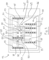
- a front view of a radar system according to various embodiments.
-
Fig. 1 schematically depicts amotor vehicle 11, also called a host vehicle, and aradar system 13 mounted to a front portion of themotor vehicle 11. Theradar system 13 is connected to anelectronic processing device 15, for example an advanced driver assistance system or an autonomous driving system. In operation, themotor vehicle 11 is moving in a drivingdirection 17 in atraffic space 19, for example a road.Objects 20, such as other vehicles, pedestrians or stationary obstacles, may be located in thetraffic space 19. - The
radar system 13 is configured for transmitting at least oneprimary radar signal 21 into thetraffic space 19 and for detectingobjects 20 present in thetraffic space 19 on the basis of at least onesecondary radar signal 22 reflected by theobjects 20, as is generally known in the art. - According to various embodiments, as depicted in
Figs. 2 and3 , theradar system 13 comprises acontrol board 25 carrying aradar circuit 27 for generating and processing radar signals. Theradar circuit 27 may be configured as a monolithic microwave integrated circuit (MMIC). As exemplarily shown, theradar circuit 27 comprises threeradar transmitters 28 and fourradar receivers 29. The number ofradar transmitters 28 andradar receivers 29 may vary dependent on the application. - Further, the
radar system 13 comprises aradar antenna assembly 30 for transmitting primary radar signals 21 into the traffic space 19 (Fig. 1 ) and for receiving secondary radar signals 22 reflected byobjects 20 present in thetraffic space 19. Theradar transmitters 28 and theradar receivers 29 are connected to respective antenna elements 33 (Fig. 3 ) of theradar antenna assembly 30 via adistribution network 31. Thedistribution network 31 may be based on a metallized plastic layer. According to an alternative embodiment, not shown, thedistribution network 31 is omitted and a direct connection of theradar transmitters 28 and theradar receivers 29 to therespective antenna elements 33 is provided. Theantenna elements 33 may comprisedielectric radiators 35, for example slot radiators adapted for a frequency of 77 GHz. - The
radar system 13 is integrated in acrash beam 37 of thevehicle 11. Specifically, thecrash beam 37 defines acavity 39 in which thecontrol board 25 is arranged. Thecavity 39 is defined between afront section 41 and arear section 42 of thecrash beam 37. Thecrash beam 37, which may be made from steel or another metal, is fixedly connected to a frame or a body of the vehicle 11 (Fig. 1 ). For example, thecrash beam 37 may be configured as a hollow profile. Both thefront section 41 and therear section 42 are shaped plate-like or sheet-like. Dependent on the application, they may be curved instead of planar as shown. - The
radar circuit 27 comprises a ground plane connector, not shown, which is electrically connected to thefront section 41 of thecrash beam 37. Thus, thefront section 41 of thecrash beam 37 forms anantenna ground plane 45 of theradar antenna assembly 30. A separate antenna ground plane incorporated in thecontrol board 25, such as a copper foil, is not necessary. - As shown, the
radar circuit 27 is arranged at therear surface 47 of thefront section 41, whereas theantenna elements 33 are arranged at thefront surface 48 of thefront section 41. In a mounted state of thecrash beam 37, thefront surface 48 faces away from a central portion of thevehicle 11. Ahousing 49 enclosing thecontrol board 25 is attached to therear surface 47 of thefront section 41. - To enable individual connections of the
radar circuit 27 to theantenna elements 33, transitions orducts 50 are provided in thefront section 41 of thecrash beam 37. Theducts 50 respectively extend from thefront surface 48 to therear surface 47 of thefront section 41. Waveguide members 51 (Fig. 3 ) connecting theradar transmitters 28 and the radar transceivers 29 (Fig. 2 ) to theantenna elements 33 are guided through theducts 50. The ground plane connector may be electrically connected to thefront section 41 of thecrash beam 27 in the region of theducts 50. - The
ducts 50 may be holes or passages that have been drilled or cut into aregular crash beam 37. Alternatively, thecrash beam 37 may have a recess, not shown, into which a separately fabricated insert member comprising theducts 50 is inserted. - As can be seen in
Fig. 3 , some of theantenna elements 33 are laterally spaced apart from thecontrol board 25. Due to the formation of theground plane 45 by thefront section 41 of thecrash beam 37, the effective antenna size of theradar antenna assembly 30 is not limited to the size of thecontrol board 25. Therefore, the resolution of theradar antenna assembly 30 is high. In particular, a large horizontal distance betweenantenna elements 33 enables a high azimuthal resolution, whereas a large vertical distance betweenantenna elements 33 enables a high elevational resolution. Dependent on the application and on the shape of thecrash beam 37, the azimuthal resolution or the elevational resolution may be maximized. Since the antenna design is not determined by the size and the shape of thecontrol board 25, there is an increased flexibility with respect to the operational parameters of theradar system 13. - Since at least some of the parts of the
radar system 13 are received in thecavity 39 which is present anyway, only little installation space is required. - At least a portion of the
radar antenna assembly 30 and/or of thewaveguide members 51 may be integrated in aflat carrier 56 attached to thefront surface 48. Theflat carrier 56 may be made from a plastic material. Thecarrier 56 may be pressed against thefront surface 48 by means ofscrews 55 or other fastening elements to enhance the stability of the assembly and to improve the electrical connection between theground plane 45 and theantenna assembly 30. - A method for fabricating the disclosed
radar system 13 comprises the step of forming theducts 50 in thecrash beam 37 and of attaching thecontrol board 25 as well as thehousing 49 to therear surface 47 of thefront section 41 of thecrash beam 37. The method further comprises the steps of guiding thewaveguide members 51 through theducts 50 and of attaching theantenna elements 33 to thefront surface 48 of thefront section 41 of thecrash beam 37, for example by means of alignment pins, not shown, and/or a conductive adhesive. Thewaveguide members 51 may comprise interfaces, not shown, to enable a connection of the front surface part and the rear surface part of theradar system 13, for example by plugging and/or gluing the parts together. The interfaces may be located at or in theducts 50. The method further comprises electrically connecting the ground plane connector to thefront section 41 of thecrash beam 37. This may be achieved indirectly by attaching theantenna elements 33 to thefront surface 48 in an electrically conducting manner. - A method for fabricating the disclosed
radar system 13 may alternatively comprise the steps of providing a metallic plate member, not shown, of forming theducts 50 in the metallic plate member and of attaching thecontrol board 25 as well as thehousing 49 to a rear surface of the metallic plate member. The method may further comprise the step of guiding thewaveguide members 51 through theducts 50 and of attaching theantenna elements 33 to a front surface of the metallic plate member. The method may further comprise the steps of electrically connecting the ground plane connector to the metallic plate member and of inserting the metallic plate member into a recess of a crash beam. - Instead of the
crash beam 37, another existing body or frame structure of thevehicle 11 may be used as anantenna ground plane 45. Thus, the ground plane connector may be electrically connected to another metallic component of the vehicle11, for example to an A-pillar, a bumper or a door. It is possible to arrange theradar system 13 at a bended portion of a metallic component, for example to form a corner radar system. - The use of an existing metallic structure of a
vehicle 11 as an antenna ground plane is possible in connection with a wide variety of antenna types, for example bistatic, grouped and multiple input multiple output antennas. -
- 11
- motor vehicle
- 13
- radar system
- 15
- electronic processing device
- 17
- driving direction
- 19
- traffic space
- 20
- object
- 21
- primary radar signal
- 22
- secondary radar signal
- 25
- control board
- 27
- radar circuit
- 28
- radar transmitter
- 29
- radar receiver
- 30
- radar antenna assembly
- 31
- distribution network
- 33
- antenna element
- 35
- dielectric radiator
- 37
- crash beam
- 39
- cavity
- 41
- front section
- 42
- rear section
- 45
- ground plane
- 47
- rear surface
- 48
- front surface
- 49
- housing
- 50
- duct
- 51
- waveguide member
- 55
- screw
- 56
- carrier
Claims (15)
- Radar system (13) for a vehicle (11), the radar system (13) comprising- a radar circuit (27) for generating and processing radar signals (21, 22), wherein the radar circuit (27) comprises a ground plane connector for an electrical connection with an antenna ground plane (45),- a radar antenna assembly (30) for transmitting radar signals (21) into a traffic space (19) and for receiving radar signals (22) reflected by objects (20) present in the traffic space (19), and- a component (37) of the vehicle,wherein the ground plane connector is electrically connected to the component (37) of the vehicle (11).
- The radar system of claim 1,
wherein the component (37) of the vehicle (11) has a front surface (48) and an opposing rear surface (47), wherein the radar circuit (27) is arranged at the rear surface (47) of the metallic component and at least one antenna element (33) of the radar antenna assembly (30) is arranged at the front surface (48) of the component (37). - The radar system of claim 2,
wherein, in a mounted state of the component (37) of the vehicle (11), the front surface (48) faces away from a center of the vehicle (11). - The radar system of claim 2 or claim 3,
wherein the component (37) comprises at least one duct (50) extending from the front surface (48) to the rear surface (47) and wherein the at least one antenna element (33) is connected to the radar circuit (27) via a waveguide member (51) guided through the at least one duct (50) of the component (37). - The radar system of claim 4,
wherein the ground plane connector is electrically connected to the component (37) in or at the duct (50). - The radar system of at least any one of claims 1 to 5,
wherein the component (37) comprises a plate-like or sheet-like portion (41). - The radar system of at least any one of claims 1 to 6,
wherein the component (37) forms at least a part of a crash beam, a bumper, a pillar or a door of the vehicle (11). - The radar system of at least any one of claims 1 to 7,
wherein the component (37) has a recess and an insert member insertable into the recess, wherein the ground plane connector is electrically connected to the insert member. - The radar system of at least any one of claims 1 to 8,
wherein the radar circuit (27) is formed on a printed circuit board (25). - The radar system of claim 9,
wherein the printed circuit board (25) is configured without any ground plane layer. - The radar system of claim 9 or claim 10,
wherein at least one antenna element (33) of the radar antenna assembly (30) is spaced apart from the printed circuit board (25). - The radar system of at least any one of claims 1 to 11,
wherein the component (37) has a surface area of at least 400 cm2, in particular of at least 1000 cm2. - Vehicle (11) comprising a chassis, a body and the radar system (13) of at least any one of claims 1 to 12, wherein the component (37) is a portion of the chassis or the body.
- Method for fabricating a radar system (13) for a vehicle (11), in particular the radar system (13) of at least any one of claims 1 to 12, wherein the method comprises the following steps:- attaching a radar circuit (27) to a component (37) of a vehicle (11), wherein the radar circuit (27) is configured to generate and process radar signals (21, 22) and wherein the radar circuit (27) comprises a ground plane connector for an electrical connection with an antenna ground plane (45),- attaching a radar antenna assembly (30) for transmitting radar signals (21) into a traffic space and for receiving radar signals (22) reflected by objects (20) present in the traffic space (19) to the component (37) of the vehicle (11), and- electrically connecting the ground plane connector to the component (37) of the vehicle (11).
- Method for fabricating a radar system (13) for a vehicle (11), in particular the radar system (13) of at least any one of claims 1 to 12, wherein the method comprises the following steps:- attaching a radar circuit (27) to a metallic plate member, wherein the radar circuit (27) is configured to generate and process radar signals (21, 22) and wherein the radar circuit (27) comprises a ground plane connector for an electrical connection with an antenna ground plane (45),- attaching a radar antenna assembly (30) for transmitting radar signals (21) into a traffic space (19) and for receiving radar signals (22) reflected by objects (20) present in the traffic space (19) to the metallic plate member,- electrically connecting the ground plane connector to the metallic plate member, and- attaching the metallic plate member to a component (37) of the vehicle (11).
Priority Applications (4)
| Application Number | Priority Date | Filing Date | Title |
|---|---|---|---|
| EP21190090.7A EP4130783A1 (en) | 2021-08-06 | 2021-08-06 | Radar system for a vehicle |
| CN202222035397.0U CN218099578U (en) | 2021-08-06 | 2022-08-03 | Radar system for vehicle and vehicle |
| CN202210926183.4A CN115704880A (en) | 2021-08-06 | 2022-08-03 | Radar system for a vehicle, vehicle and method for producing a radar system |
| US17/817,930 US20230037906A1 (en) | 2021-08-06 | 2022-08-05 | Radar System for a Vehicle |
Applications Claiming Priority (1)
| Application Number | Priority Date | Filing Date | Title |
|---|---|---|---|
| EP21190090.7A EP4130783A1 (en) | 2021-08-06 | 2021-08-06 | Radar system for a vehicle |
Publications (1)
| Publication Number | Publication Date |
|---|---|
| EP4130783A1 true EP4130783A1 (en) | 2023-02-08 |
Family
ID=77249734
Family Applications (1)
| Application Number | Title | Priority Date | Filing Date |
|---|---|---|---|
| EP21190090.7A Pending EP4130783A1 (en) | 2021-08-06 | 2021-08-06 | Radar system for a vehicle |
Country Status (3)
| Country | Link |
|---|---|
| US (1) | US20230037906A1 (en) |
| EP (1) | EP4130783A1 (en) |
| CN (2) | CN218099578U (en) |
Citations (4)
| Publication number | Priority date | Publication date | Assignee | Title |
|---|---|---|---|---|
| EP0978729A2 (en) * | 1998-08-07 | 2000-02-09 | Hitachi, Ltd. | High-frequency transmitter-receiving apparatus for such an application as vehicle-onboard radar system |
| DE10109371A1 (en) * | 2000-05-15 | 2001-11-29 | Hitachi Ltd | Radio wave radar for vehicles |
| DE10060603A1 (en) * | 2000-12-05 | 2002-06-13 | Daimler Chrysler Ag | Vehicle bodywork part with integrated antenna e.g. for communications devices such as mobile phone or navigation systems, has carrier unit made of electrically non-conducting material |
| JP2019009713A (en) * | 2017-06-28 | 2019-01-17 | マツダ株式会社 | On-vehicle antenna, on-vehicle radar device including the same, and manufacturing method foe on-vehicle antenna |
-
2021
- 2021-08-06 EP EP21190090.7A patent/EP4130783A1/en active Pending
-
2022
- 2022-08-03 CN CN202222035397.0U patent/CN218099578U/en active Active
- 2022-08-03 CN CN202210926183.4A patent/CN115704880A/en active Pending
- 2022-08-05 US US17/817,930 patent/US20230037906A1/en active Pending
Patent Citations (4)
| Publication number | Priority date | Publication date | Assignee | Title |
|---|---|---|---|---|
| EP0978729A2 (en) * | 1998-08-07 | 2000-02-09 | Hitachi, Ltd. | High-frequency transmitter-receiving apparatus for such an application as vehicle-onboard radar system |
| DE10109371A1 (en) * | 2000-05-15 | 2001-11-29 | Hitachi Ltd | Radio wave radar for vehicles |
| DE10060603A1 (en) * | 2000-12-05 | 2002-06-13 | Daimler Chrysler Ag | Vehicle bodywork part with integrated antenna e.g. for communications devices such as mobile phone or navigation systems, has carrier unit made of electrically non-conducting material |
| JP2019009713A (en) * | 2017-06-28 | 2019-01-17 | マツダ株式会社 | On-vehicle antenna, on-vehicle radar device including the same, and manufacturing method foe on-vehicle antenna |
Also Published As
| Publication number | Publication date |
|---|---|
| CN115704880A (en) | 2023-02-17 |
| US20230037906A1 (en) | 2023-02-09 |
| CN218099578U (en) | 2022-12-20 |
Similar Documents
| Publication | Publication Date | Title |
|---|---|---|
| US11604273B2 (en) | Radar system for detecting the environment of a motor vehicle having a plastic antenna | |
| US11536829B2 (en) | Vehicle radar system with radar embedded into radome | |
| KR102009701B1 (en) | Waveguide tube slot antenna and wireless device provided therewith | |
| EP3647807B1 (en) | Radar assembly with a slot transition through a printed circuit board | |
| US11515624B2 (en) | Integrated cavity backed slot array antenna system | |
| US20180233812A1 (en) | Radome and vehicular radar apparatus comprising same | |
| US20200343626A1 (en) | Rf devices including conformal antennas and methods for manufacturing thereof | |
| US6452550B1 (en) | Reduction of the effects of process misalignment in millimeter wave antennas | |
| CN111668589B (en) | Signal device including slot transition between substrate integrated waveguide and signal generator | |
| US7019707B2 (en) | Microwave antenna | |
| EP4130783A1 (en) | Radar system for a vehicle | |
| US10547113B2 (en) | Blind mate waveguide flange usable in chipset testing | |
| CN218213411U (en) | Radar system for vehicle | |
| CN218099579U (en) | Radar antenna assembly for vehicle, radar system for vehicle and vehicle | |
| US20160093956A1 (en) | Radar apparatus | |
| CN214957333U (en) | Angle radar and vehicle | |
| CN217306728U (en) | Power divider, antenna device, radio device, and apparatus | |
| CN114649661B (en) | Waveguide with radiating slot and parasitic element for asymmetric cladding | |
| CN114649659B (en) | Sawtooth waveguide with grating lobes for suppression | |
| US20240125913A1 (en) | Vehicular radar system with enhanced waveguide and antenna | |
| CN117134088A (en) | Vertical microstrip waveguide transition | |
| WO2023110558A1 (en) | Radar device arrangement for a vehicle and method to produce a radar device arrangement for a vehicle | |
| EP4187272A1 (en) | Detection apparatus, manufacturing method for detection apparatus, and terminal comprising detection apparatus | |
| EP4340126A1 (en) | Antenna unit, radar, and terminal device | |
| CN114649671A (en) | Double-wire feed dipole array antenna |
Legal Events
| Date | Code | Title | Description |
|---|---|---|---|
| PUAI | Public reference made under article 153(3) epc to a published international application that has entered the european phase |
Free format text: ORIGINAL CODE: 0009012 |
|
| STAA | Information on the status of an ep patent application or granted ep patent |
Free format text: STATUS: THE APPLICATION HAS BEEN PUBLISHED |
|
| AK | Designated contracting states |
Kind code of ref document: A1 Designated state(s): AL AT BE BG CH CY CZ DE DK EE ES FI FR GB GR HR HU IE IS IT LI LT LU LV MC MK MT NL NO PL PT RO RS SE SI SK SM TR |
|
| RAP3 | Party data changed (applicant data changed or rights of an application transferred) |
Owner name: APTIV TECHNOLOGIES LIMITED |
|
| STAA | Information on the status of an ep patent application or granted ep patent |
Free format text: STATUS: REQUEST FOR EXAMINATION WAS MADE |
|
| 17P | Request for examination filed |
Effective date: 20230711 |
|
| RBV | Designated contracting states (corrected) |
Designated state(s): AL AT BE BG CH CY CZ DE DK EE ES FI FR GB GR HR HU IE IS IT LI LT LU LV MC MK MT NL NO PL PT RO RS SE SI SK SM TR |