EP4130768B1 - Method and apparatus for calculating relative state-of-charge of battery - Google Patents
Method and apparatus for calculating relative state-of-charge of battery Download PDFInfo
- Publication number
- EP4130768B1 EP4130768B1 EP22184774.2A EP22184774A EP4130768B1 EP 4130768 B1 EP4130768 B1 EP 4130768B1 EP 22184774 A EP22184774 A EP 22184774A EP 4130768 B1 EP4130768 B1 EP 4130768B1
- Authority
- EP
- European Patent Office
- Prior art keywords
- battery
- rsoc
- soc
- variation amount
- capacity
- Prior art date
- Legal status (The legal status is an assumption and is not a legal conclusion. Google has not performed a legal analysis and makes no representation as to the accuracy of the status listed.)
- Active
Links
Images

Classifications
-
- G—PHYSICS
- G01—MEASURING; TESTING
- G01R—MEASURING ELECTRIC VARIABLES; MEASURING MAGNETIC VARIABLES
- G01R31/00—Arrangements for testing electric properties; Arrangements for locating electric faults; Arrangements for electrical testing characterised by what is being tested not provided for elsewhere
- G01R31/36—Arrangements for testing, measuring or monitoring the electrical condition of accumulators or electric batteries, e.g. capacity or state of charge [SoC]
- G01R31/382—Arrangements for monitoring battery or accumulator variables, e.g. SoC
- G01R31/3842—Arrangements for monitoring battery or accumulator variables, e.g. SoC combining voltage and current measurements
-
- G—PHYSICS
- G01—MEASURING; TESTING
- G01R—MEASURING ELECTRIC VARIABLES; MEASURING MAGNETIC VARIABLES
- G01R31/00—Arrangements for testing electric properties; Arrangements for locating electric faults; Arrangements for electrical testing characterised by what is being tested not provided for elsewhere
- G01R31/36—Arrangements for testing, measuring or monitoring the electrical condition of accumulators or electric batteries, e.g. capacity or state of charge [SoC]
- G01R31/3644—Constructional arrangements
- G01R31/3648—Constructional arrangements comprising digital calculation means, e.g. for performing an algorithm
-
- G—PHYSICS
- G01—MEASURING; TESTING
- G01R—MEASURING ELECTRIC VARIABLES; MEASURING MAGNETIC VARIABLES
- G01R31/00—Arrangements for testing electric properties; Arrangements for locating electric faults; Arrangements for electrical testing characterised by what is being tested not provided for elsewhere
- G01R31/36—Arrangements for testing, measuring or monitoring the electrical condition of accumulators or electric batteries, e.g. capacity or state of charge [SoC]
- G01R31/367—Software therefor, e.g. for battery testing using modelling or look-up tables
-
- G—PHYSICS
- G01—MEASURING; TESTING
- G01R—MEASURING ELECTRIC VARIABLES; MEASURING MAGNETIC VARIABLES
- G01R31/00—Arrangements for testing electric properties; Arrangements for locating electric faults; Arrangements for electrical testing characterised by what is being tested not provided for elsewhere
- G01R31/36—Arrangements for testing, measuring or monitoring the electrical condition of accumulators or electric batteries, e.g. capacity or state of charge [SoC]
- G01R31/374—Arrangements for testing, measuring or monitoring the electrical condition of accumulators or electric batteries, e.g. capacity or state of charge [SoC] with means for correcting the measurement for temperature or ageing
-
- G—PHYSICS
- G01—MEASURING; TESTING
- G01R—MEASURING ELECTRIC VARIABLES; MEASURING MAGNETIC VARIABLES
- G01R31/00—Arrangements for testing electric properties; Arrangements for locating electric faults; Arrangements for electrical testing characterised by what is being tested not provided for elsewhere
- G01R31/36—Arrangements for testing, measuring or monitoring the electrical condition of accumulators or electric batteries, e.g. capacity or state of charge [SoC]
- G01R31/382—Arrangements for monitoring battery or accumulator variables, e.g. SoC
-
- G—PHYSICS
- G01—MEASURING; TESTING
- G01R—MEASURING ELECTRIC VARIABLES; MEASURING MAGNETIC VARIABLES
- G01R31/00—Arrangements for testing electric properties; Arrangements for locating electric faults; Arrangements for electrical testing characterised by what is being tested not provided for elsewhere
- G01R31/36—Arrangements for testing, measuring or monitoring the electrical condition of accumulators or electric batteries, e.g. capacity or state of charge [SoC]
- G01R31/392—Determining battery ageing or deterioration, e.g. state of health
-
- G—PHYSICS
- G01—MEASURING; TESTING
- G01R—MEASURING ELECTRIC VARIABLES; MEASURING MAGNETIC VARIABLES
- G01R31/00—Arrangements for testing electric properties; Arrangements for locating electric faults; Arrangements for electrical testing characterised by what is being tested not provided for elsewhere
- G01R31/36—Arrangements for testing, measuring or monitoring the electrical condition of accumulators or electric batteries, e.g. capacity or state of charge [SoC]
- G01R31/396—Acquisition or processing of data for testing or for monitoring individual cells or groups of cells within a battery
-
- H—ELECTRICITY
- H02—GENERATION; CONVERSION OR DISTRIBUTION OF ELECTRIC POWER
- H02J—ELECTRIC POWER NETWORKS; CIRCUIT ARRANGEMENTS OR SYSTEMS FOR SUPPLYING OR DISTRIBUTING ELECTRIC POWER; SYSTEMS FOR STORING ELECTRIC ENERGY
- H02J7/00—Circuit arrangements for charging or discharging batteries or for supplying loads from batteries
- H02J7/80—Circuit arrangements for charging or discharging batteries or for supplying loads from batteries including monitoring or indicating arrangements
- H02J7/82—Control of state of charge [SOC]
Definitions
- the disclosure relates to a method, a computer program, and an apparatus for calculating a relative state-of-charge of a battery, which may effectively calculate the relative state-of-charge of the battery in a process of calculating the relative state-of-charge of the battery.
- Lithium batteries have a designed intrinsic capacity, but depending on the surrounding environment, lithium batteries may not use all of the intrinsic capacity, and thus, the intrinsic capacity and available capacity generally differ.
- the available capacity is referred to as relative capacity, and a value obtained by smoothing the relative capacity is defined as a relative state-of-charge (RSOC, %).
- the estimation of relative capacity may be useful because the relative capacity is an indicator for a user of a lithium battery to know how much lithium battery may be used.
- the relative capacity may be estimated by calculating an RSOC, and research on the estimation of the relative capacity of a battery is being actively conducted.
- the RSOC may drop sharply at the end of the battery's discharge, which may cause various problems, such as a sudden power-off of a product, and thus, various attempts have been made to improve the accuracy of the estimation of the relative capacity of a battery.
- the disclosure provides a solution to the problems stated above, and provides a method, a computer program, and an apparatus for calculating a relative state-of-charge (RSOC) of a battery, which may effectively reduce or prevent an RSOC plunge of the battery.
- RSOC relative state-of-charge
- a method of calculating a relative state-of-charge of a battery according to claim 1 there is provided a method of calculating a relative state-of-charge of a battery according to claim 1.
- spatially relative terms such as “beneath,” “below,” “lower,” “under,” “above,” “upper,” and the like, may be used herein for ease of explanation to describe one element or feature's relationship to another element(s) or feature(s) as illustrated in the figures. It will be understood that the spatially relative terms are intended to encompass different orientations of the device in use or in operation, in addition to the orientation depicted in the figures. For example, if the device in the figures is turned over, elements described as “below” or “beneath” or “under” other elements or features would then be oriented “above” the other elements or features. Thus, the example terms “below” and “under” can encompass both an orientation of above and below.
- the device may be otherwise oriented (e.g., rotated 90 degrees or at other orientations) and the spatially relative descriptors used herein should be interpreted accordingly.
- first part is described as being arranged "on" a second part, this indicates that the first part is arranged at an upper side or a lower side of the second part without the limitation to the upper side thereof on the basis of the gravity direction.
- a layer, region, or component when a layer, region, or component is referred to as being “electrically connected” or “electrically coupled” to another layer, region, or component, it can be directly electrically connected or coupled to the other layer, region, and/or component or intervening layers, regions, or components may be present.
- “directly connected/directly coupled,” or “directly on,” refers to one component directly connecting or coupling another component, or being on another component, without an intermediate component.
- other expressions describing relationships between components such as “between,” “immediately between” or “adjacent to” and “directly adjacent to” may be construed similarly.
- an element or layer when referred to as being “between” two elements or layers, it can be the only element or layer between the two elements or layers, or one or more intervening elements or layers may also be present.
- "at least one of X, Y, and Z,” “at least one of X, Y, or Z,” and “at least one selected from the group consisting of X, Y, and Z” may be construed as X only, Y only, Z only, any combination of two or more of X, Y, and Z, such as, for instance, XYZ, XYY, YZ, and ZZ, or any variation thereof.
- the expression such as “at least one of A and B” may include A, B, or A and B.
- “or” generally means “and/or,” and the term “and/or” includes any and all combinations of one or more of the associated listed items.
- the expression such as “A and/or B” may include A, B, or A and B.
- first, second, third, etc. may be used herein to describe various elements, components, regions, layers and/or sections, these elements, components, regions, layers and/or sections should not be limited by these terms. These terms are used to distinguish one element, component, region, layer or section from another element, component, region, layer or section. Thus, a first element, component, region, layer or section described below could be termed a second element, component, region, layer or section, without departing from the scope of the present disclosure. The description of an element as a “first” element may not require or imply the presence of a second element or other elements.
- the terms “first”, “second”, etc. may also be used herein to differentiate different categories or sets of elements. For conciseness, the terms “first”, “second”, etc. may represent “first-category (or first-set)", “second-category (or second-set)”, etc., respectively.
- a specific process order may be performed differently from the described order.
- two consecutively described processes may be performed substantially at the same time or performed in an order opposite to the described order.
- the term “substantially,” “about,” “approximately,” and similar terms are used as terms of approximation and not as terms of degree, and are intended to account for the inherent deviations in measured or calculated values that would be recognized by those of ordinary skill in the art.
- “About” or “approximately,” as used herein, is inclusive of the stated value and means within an acceptable range of deviation for the particular value as determined by one of ordinary skill in the art, considering the measurement in question and the error associated with measurement of the particular quantity (i.e., the limitations of the measurement system). For example, “about” may mean within one or more standard deviations, or within ⁇ 30%, 20%, 10%, 5% of the stated value. Further, the use of “may” when describing embodiments of the present disclosure refers to "one or more embodiments of the present disclosure.”
- any numerical range disclosed and/or recited herein is intended to include all sub-ranges of the same numerical precision subsumed within the recited range.
- a range of "1.0 to 10.0" is intended to include all subranges between (and including) the recited minimum value of 1.0 and the recited maximum value of 10.0, that is, having a minimum value equal to or greater than 1.0 and a maximum value equal to or less than 10.0, such as, for example, 2.4 to 7.6.
- Any maximum numerical limitation recited herein is intended to include all lower numerical limitations subsumed therein, and any minimum numerical limitation recited in this specification is intended to include all higher numerical limitations subsumed therein.
- Some embodiments may be described in terms of functional block components and various processing steps. Some or all of such functional blocks may be realized by any number of hardware and/or software components configured to perform the specified functions.
- functional blocks of the disclosure may be implemented by one or more microprocessors or by circuit components for a predetermined function.
- Functional blocks of the disclosure may be implemented with any programming or scripting language.
- Functional blocks of the disclosure may be implemented in algorithms that are executed on one or more processors.
- a function performed by a functional block in the disclosure may be performed by a plurality of functional blocks, or functions performed by a plurality of functional blocks in the disclosure may be performed by one functional block.
- the disclosure could employ any number of conventional techniques for electronics configuration, signal processing and/or control, data processing, and the like.
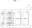
- FIG. 1 schematically shows a battery pack according to one or more embodiments of the disclosure.
- the battery 110 includes at least one battery cell 111, and the battery cell 111 is a chargeable secondary battery.
- the battery cell 111 may include at least one selected from the group consisting of a nickel-cadmium battery, a lead storage battery, a nickel metal hydride (NiMH) battery, a lithium ion battery, a lithium polymer battery, and the like.
- the number and connection method of battery cells 111 included in the battery 110 may be determined based on an amount of electric power and voltage, which are suitable for the battery pack 100.
- FIG. 1 shows, for conceptual purposes only, that battery cells 111 included in the battery 110 are connected in series, the battery cells 111 are connected with each other in parallel or connected with each other in series and in parallel.
- FIG. 1 shows, for conceptual purposes, that battery pack 100 only includes one battery 110, the battery pack 100 may include a plurality of batteries 110 connected with each other in series, in parallel, or both in series and in parallel.
- the battery 110 may also include only one battery cell 111.
- Each of the batteries 110 may include a plurality of battery modules including a plurality of battery cells 111.
- the battery pack 100 includes a pair of pack terminals 101 and 102 to which an electrical load or a charging device may be connected.
- the battery pack 100 may include a switch.
- the switch may be connected between the battery 110 and one of the pack terminals 101 and 102 (for example, the pack terminal 101).
- the switch may be controlled by the processor 150.
- the battery pack 100 may further include a battery protection circuit, a fuse, a current sensor, and the like.
- the processor 150 controls overall operation of the apparatus for calculating an RSOC of a battery.
- the processor 150 may be implemented in a form that selectively includes a processor known in the art, an application-specific integrated circuit (ASIC), a chipset, a logic circuit, a register, a communication modem, and/or a data processing device, so as to perform the operation described above.
- ASIC application-specific integrated circuit
- the memory 160 is a recording medium that is readable by the processor 150, and may include a permanent mass storage device, such as random access memory (RAM), read only memory (ROM), and a disk drive.
- the memory 160 may store an operating system and at least one program or application code.
- the memory 160 may store program code for calculating an RSOC of a battery, according to one or more embodiments of the disclosure.
- the memory 160 stores data generated by measuring at least one parameter of the battery 110.
- the memory 160 stores an intrinsic capacity value of the battery 110.
- the memory 160 stores SOC-open circuit voltage (SOC-OCV) data of the battery 110.
- the data may include charging/discharging current, terminal voltage and/or temperature of the battery 110.
- the apparatus for calculating an RSOC of a battery may further include the voltmeter 120 for measuring at least one parameter of the battery 110, the ammeter 130, and the thermometer 140.
- the apparatus for calculating an RSOC of a battery may further include a communication module for communicating with other devices, such as an electronic control device of a vehicle, a controller of a charging device, and the like.
- the voltmeter 120 may be configured to measure a voltage of the battery 110.
- the voltmeter 120 may be electrically connected to both ends of the battery 110 and/or the battery cell 111.
- the voltmeter 120 may be electrically connected to the processor 150 to transmit and receive electrical signals.
- the voltmeter 120 may measure a voltage of both ends of the battery 110 and/or the battery cell 111 at a time interval under the control by the processor 150, and may output a signal indicating a magnitude of the measured voltage to the processor 150.
- the processor 150 may determine the voltage of the battery 110 and/or the battery cell 111 from the signal output from the voltmeter 120.
- the voltmeter 120 may be implemented by using a voltage measurement circuit that is generally used in the art.
- the thermometer 140 may be configured to measure a temperature of the battery 110.
- the thermometer 140 may be connected to the battery 110 and/or the battery cell 111 to measure a temperature of a secondary battery provided in the battery 110 and/or the battery cell 111.
- the thermometer 140 may be electrically connected to the processor 150 to transmit and receive an electrical signal.
- the thermometer 140 may repeatedly measure a temperature of the secondary battery at a time interval, and may output a signal indicating a magnitude of the measured temperature to the processor 150.
- the processor 150 may determine the temperature of the secondary battery from the signal output from the thermometer 140.
- the thermometer 140 may be implemented by using a thermocouple generally used in the art.
- the processor 150 estimates an SOC of the battery 110 by using at least one of a voltage measurement value, a current measurement value, and a temperature measurement value of the battery 110, which are received from the voltmeter 120, the ammeter 130, and the thermometer 140, respectively.
- the SOC is calculated as a value corresponding to a remaining amount of the battery 110 in the range of about 0 % to about 100 %.
- the processor 150 may estimate an SOC of the battery 110 by integrating a charging/discharging current of the battery 110.
- an initial value of the SOC may be determined by using an OCV of the battery 110, which may have been measured before the charging or discharging of the battery 110 began.
- the processor 150 may map an SOC corresponding to an OCV of the battery 110 from SOC-OCV data, based on the SOC-OCV data in which an SOC is defined for each OCV.
- SOC SOC i ⁇ 1 + dSOC
- SOC refers to the state-of-charge of a battery
- SOC i-1 refers to an initial value of the state-of-charge of the battery
- dSOC refers to a value obtained by integrating a charging/discharging current of the battery.
- dSOC refers to a value obtained by integrating the value obtained by integrating the charging/discharging current of the battery from the start of charging or discharging
- intrinsic capacity refers to design capacity of the battery.
- the processor 150 may estimate an SOC of the battery 110 by using an extended Kalman filter.
- the extended Kalman filter refers to a mathematical algorithm for adaptively estimating an SOC of a secondary battery by using a voltage, current, and temperature of the secondary battery.
- the SOC of the battery 110 may also be determined by other known methods by which the SOC may be estimated by selectively utilizing a voltage, current, and temperature of a secondary battery than the current integration method or extended Kalman filter described above.
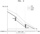
- FIG. 2 is a diagram for explaining a relationship between an SOC, an available SOC (AvSOC), and an RSOC of a battery according to one or more embodiments of the disclosure.
- an SOC of a battery being discharged may be distinguished from an AvSOC and an RSOC of the battery.
- SOC refers to the state-of-charge of a battery.
- the SOC may indicate a value corresponding to a remaining amount of the battery in the range of about 0 % to about 100 %.
- AvSOC refers to the available state-of-charge of the battery.
- AvSOC may indicate a value corresponding to a currently available remaining amount of the battery, and may indicate a value that is different from the SOC depending on the surrounding environment or current state, such as temperature, a discharge rate, or non-dischargeable capacity of the battery.
- AvSOC SOC ⁇ non ⁇ dischargeable capacity intrinsic capacity ⁇ 100 %
- AvSOC refers to the available state-of-charge of a battery
- SOC refers to the state-of-charge of the battery
- non-dischargeable capacity refers to a dischargeable remaining capacity in the current state of the battery
- intrinsic capacity refers to a design capacity of the battery.
- RSOC refers to the relative state-of-charge of a battery.
- the RSOC indicates a value corresponding to relative capacity of a battery, and may indicate a value that is different from AvSOC depending on the surrounding environment or current state, such as a temperature or a discharge rate of the battery.
- RSOC RSOC i ⁇ 1 + Ratio ⁇ dSOC
- RSOC refers to the relative state-of-charge of a battery
- RSOCi-1 refers to an initial value of the relative state-of-charge of the battery
- Ratio refers to a value of a ratio of RSOC to AvSOC
- dSOC refers to a current integration value of Equation 2.
- Ratio RSOC i ⁇ 1 AvSOC
- Ratio refers to a value of a ratio of RSOC to AvSOC
- RSOCi-1 refers to an initial value of the relative state-of-charge of a battery
- AvSOC refers to the available state-of-charge of the battery.
- SOC and AvSOC of the battery may differ by a value corresponding to non-dischargeable capacity, and AvSOC and RSOC may have the same value.
- AvSOC decreases relatively sharply (e.g., "Drop"), and thus, AvSOC and RSOC may have different values.
- RSOC may be smoothed to track and follow AvSOC.
- AvSOC increases relatively sharply (e.g., "Jump"), and RSOC is smoothed to track and follow AvSOC.
- AvSOC may be about 70 %.
- the discharge rate may increase relatively sharply, and AvSOC may decrease to about 60 %, and in this case, RSOC may be displayed as about 70 % instead of about 60 % as a value displayed to a battery user.
- RSOC is smoothed to track and follow an AvSOC value.
- RSOC may be smoothed by applying an SOC variation value having a slope greater than AvSOC.
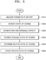
- FIG. 3 is a flowchart for explaining a method of calculating an RSOC of a battery, according to the disclosure.
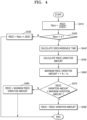
- FIG. 4 is a flowchart for explaining a method of calculating an RSOC of a battery, according to one or more other embodiments of the disclosure.
- a method of estimating a state of a battery may be performed by the processor 150 shown in FIG. 1 .
- a method of calculating an RSOC of a battery includes measuring at least one parameter of the battery (operation S310). Based on the at least one parameter, estimating an SOC of the battery (operation S320). Based on the SOC, based on SOC-OCV data of the battery, and based on the at least one parameter, estimating the non-dischargeable capacity of the battery (operation S330). Based on the non-dischargeable capacity, based on the SOC, and based on the intrinsic capacity of the battery, estimating an AvSOC of the battery (operation S340). Based on the SOC and the AvSOC, determining the RSOC of the battery (operation S350). And based on a ratio of the RSOC to the AvSOC, updating the RSOC (operation S360).
- the at least one parameter of the battery includes a voltage, current, and temperature of the battery. Also, the at least one parameter of the battery may include a discharge rate of the battery.
- the estimating of the non-dischargeable capacity of the battery may include performing a discharge simulation by using the SOC of the battery, the SOC-OCV data of the battery, and the at least one parameter, and based on a remaining capacity of the battery, which corresponds to a state-of-discharge of the battery with respect to the discharge simulation, estimating the non-dischargeable capacity of the battery.
- the discharge simulation of the battery is a simulation performed by using the SOC and SOC-OCV data of the battery.
- a voltage drop value by the product of the internal resistance and current of the battery may be calculated by using the current, terminal voltage, SOC, and SOC-OCV data of the battery.
- the remaining capacity of the battery corresponding to the state-of-discharge may be calculated via an OCV value when the battery is in the state-of-discharge and the terminal voltage becomes 0, and the non-dischargeable capacity of the battery may be estimated by using the remaining capacity.
- a method of performing the simulation would be known to a person skilled in the technical field.
- V refers to the terminal voltage of the battery
- OCV refers to the open circuit voltage of the battery
- I refers to the current of the battery
- ir refers to the internal resistance of the battery.
- the estimating of the AvSOC of the battery may include calculating a non-discharge rate of the battery, based on a ratio of the intrinsic capacity to the non-dischargeable capacity, and may also include calculating the AvSOC by subtracting the non-discharge rate from the SOC.
- the AvSOC of the battery may be calculated by subtracting the non-discharge rate of the battery from the SOC of the battery.
- the non-discharge rate of the battery may be calculated based on a ratio of the intrinsic capacity and non-dischargeable capacity of the battery.
- AvSOC SOC ⁇ non - dischargeable SOC
- AvSOC refers to an available state-of-charge of the battery
- SOC refers to a state-of-discharge of the battery
- non-dischargeable SOC refers to SOC corresponding to the non-dischargeable remaining capacity in the current state of the battery.
- the determining of the RSOC may include determining the RSOC of the battery based on the SOC and AvSOC of the battery.
- the updating of the RSOC includes calculating the ratio of the RSOC to the AvSOC (operation S410). Based on the ratio, determining whether correction of the RSOC is suitable (e.g. appropriate, and/or necessary) (operation S420), and when the correction of the RSOC is suitable, updating the RSOC by using a dischargeable time of the battery.
- Ratio refers to a value of a ratio of RSOC to AvSOC
- RSOC refers to the relative state-of-charge of the battery
- AvSOC refers to an available state-of-charge of the battery.
- an example threshold value (e.g., predetermined threshold value) for the ratio of RSOC to the AvSOC may be about 4.
- 4 may be a threshold value determined by experimental data.
- the determining of whether the correction of the RSOC is suitable may include determining whether a value of the ratio is greater than a threshold value (e.g., predetermined threshold value), and when the value of the ratio is greater than the threshold value, determining that the correction of the RSOC is suitable.
- a threshold value e.g., predetermined threshold value
- the ratio of the RSOC to the AvSOC when the ratio of the RSOC to the AvSOC is greater than 4, correcting of the RSOC may be performed. In contrast, when the ratio of the RSOC to the AvSOC is less than or equal to 4, the RSOC of the battery may be updated according to Equation 4 described above (operation S430).
- the updating of the RSOC includes calculating the dischargeable time (operation S440), calculating an RSOC variation amount by adding a variation amount weight to a value obtained by dividing a current RSOC of the battery by the dischargeable time (operation S450), and based on the RSOC variation amount, updating the RSOC.
- the variation amount weight indicates an RSOC variation amount per unit time, and the unit thereof may be %/s (e.g., a percentage change per second).
- the updating of the RSOC by using the RSOC variation amount may include determining whether the RSOC variation amount is less than a maximum RSOC variation amount (e.g., predetermined maximum RSOC variation amount) (operation S460 and operation S470), and when the RSOC variation amount is less than the maximum RSOC variation amount, updating the RSOC of the battery by using the RSOC variation amount (operation S490).
- a maximum RSOC variation amount e.g., predetermined maximum RSOC variation amount
- the maximum RSOC variation amount may be about 1 %/1s.
- the RSOC of the battery may be updated by using the maximum RSOC variation amount (operation S480).
- RSOC is effectively updated based on a ratio of RSOC to AvSOC of a battery.
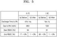
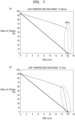
- FIGS. 5 to 7 show result data and result graphs, in which updating of an RSOC according to a discharge rate of a battery is performed according to one or more embodiments of the disclosure.
- a discharge rate at which the battery is discharged by using, for an hour, the rated capacity [unit of Ampere-hour (Ah)] of the battery is referred to as 1C discharge
- a discharge rate at which the battery is discharged by using, for 10 hours, the rated capacity of the battery is referred to as 0.1C discharge.
- the discharge time is about 47 minutes and 14 seconds
- the discharge capacity is about 2,651 mAh
- the discharge start RSOC is represented as about 94 %.
- the various embodiments described hereinbefore may be implemented in a form of a computer program executable by various components on a computer, and such a computer program may be recorded in a computer-readable medium.
- the medium may continuously store computer-executable programs, or temporarily store the computer-executable programs for execution or downloading.
- the medium may be any one of various recording media or storage media in which a single piece or plurality of pieces of hardware are combined, and the medium is not limited to a medium directly connected to a computer system, but may be distributed on a network.
- Examples of the medium include a magnetic medium, such as a hard disk, a floppy disk, and a magnetic tape, an optical recording medium, such as a CD-ROM and a DVD, a magneto-optical medium, such as a floptical disk, and ROM, RAM, and a flash memory, which are configured to store program instructions.
- Other examples of the medium include a recording medium and a storage medium managed by application stores distributing applications or by websites, servers, and the like supplying or distributing other various types of software.
- the term “unit” or “module” may be a hardware component such as a processor or circuit and/or a software component that is executed by a hardware component such as a processor.
- the "unit” or “module” may be implemented by components, such as software components, object-oriented software components, class components, and task components, processes, functions, attributes, procedures, subroutines, segments of program code, drivers, firmware, micro codes, circuits, data, a database, data structures, tables, arrays, and variables.
- a sharp decrease in RSOC which may occur at the end of the battery discharge, may be reduced or prevented.
- the scope of the disclosure is not limited by the above aspect.
Landscapes
- Physics & Mathematics (AREA)
- General Physics & Mathematics (AREA)
- Engineering & Computer Science (AREA)
- Power Engineering (AREA)
- Secondary Cells (AREA)
- Charge And Discharge Circuits For Batteries Or The Like (AREA)
Applications Claiming Priority (1)
| Application Number | Priority Date | Filing Date | Title |
|---|---|---|---|
| KR1020210103438A KR102633760B1 (ko) | 2021-08-05 | 2021-08-05 | 배터리의 상대 충전 상태를 산출하는 방법 및 장치 |
Publications (2)
| Publication Number | Publication Date |
|---|---|
| EP4130768A1 EP4130768A1 (en) | 2023-02-08 |
| EP4130768B1 true EP4130768B1 (en) | 2025-05-14 |
Family
ID=82594984
Family Applications (1)
| Application Number | Title | Priority Date | Filing Date |
|---|---|---|---|
| EP22184774.2A Active EP4130768B1 (en) | 2021-08-05 | 2022-07-13 | Method and apparatus for calculating relative state-of-charge of battery |
Country Status (5)
| Country | Link |
|---|---|
| US (1) | US12571845B2 (pl) |
| EP (1) | EP4130768B1 (pl) |
| KR (1) | KR102633760B1 (pl) |
| HU (1) | HUE071968T2 (pl) |
| PL (1) | PL4130768T3 (pl) |
Families Citing this family (2)
| Publication number | Priority date | Publication date | Assignee | Title |
|---|---|---|---|---|
| KR102877207B1 (ko) | 2023-06-15 | 2025-10-29 | 한국철도기술연구원 | 리튬 배터리 특성 추정 장치 및 방법 |
| KR20250128724A (ko) * | 2024-02-21 | 2025-08-28 | 주식회사 엘지에너지솔루션 | 배터리 용량 추정 장치 및 방법 |
Family Cites Families (15)
| Publication number | Priority date | Publication date | Assignee | Title |
|---|---|---|---|---|
| US9269994B2 (en) * | 2011-12-29 | 2016-02-23 | Blackberry Limited | Power pack remaining capacity level detection |
| JP5971344B2 (ja) * | 2012-09-21 | 2016-08-17 | 日産自動車株式会社 | 充電状態演算装置及び充電状態演算方法 |
| KR101903581B1 (ko) | 2012-11-23 | 2018-10-04 | 미쓰미덴기가부시기가이샤 | 전지상태 계측 방법 및 전지상태 계측 장치 |
| CN103852725B (zh) * | 2012-11-30 | 2018-05-01 | 凹凸电子(武汉)有限公司 | 用于估算电池剩余容量的设备、方法及系统 |
| KR102177723B1 (ko) | 2013-10-31 | 2020-11-11 | 현대모비스 주식회사 | 차량용 배터리의 가용 용량 연산 방법 및 컴퓨터 판독 가능한 기록 매체 |
| GB2537406B (en) * | 2015-04-16 | 2017-10-18 | Oxis Energy Ltd | Method and apparatus for determining the state of health and state of charge of lithium sulfur batteries |
| KR102040880B1 (ko) * | 2016-04-11 | 2019-11-05 | 주식회사 엘지화학 | 배터리 상태 추정 장치 및 방법 |
| US10983168B2 (en) * | 2016-11-18 | 2021-04-20 | Semiconductor Components Industries, Llc | Methods and apparatus for reporting a relative state of charge of a battery |
| US10184987B2 (en) * | 2016-11-18 | 2019-01-22 | Semiconductor Components Industries, Llc | Methods and apparatus for reporting a relative state of charge of a battery |
| US10312699B2 (en) * | 2017-07-31 | 2019-06-04 | Robert Bosch Gmbh | Method and system for estimating battery open cell voltage, state of charge, and state of health during operation of the battery |
| KR102349235B1 (ko) * | 2018-02-14 | 2022-01-07 | 주식회사 엘지에너지솔루션 | 배터리의 충전 상태를 추정하기 위한 장치 및 방법 |
| KR102452626B1 (ko) * | 2018-03-07 | 2022-10-06 | 주식회사 엘지에너지솔루션 | Soc-ocv 프로파일 추정 방법 및 장치 |
| US11255919B2 (en) * | 2019-09-12 | 2022-02-22 | Semiconductor Components Industries, Llc | Methods and system for a battery |
| CN110752635A (zh) * | 2019-10-12 | 2020-02-04 | 山东大学 | 串联电池组容量在线监测和充放电双状态均衡电路及方法 |
| TWI758760B (zh) * | 2020-06-24 | 2022-03-21 | 仁寶電腦工業股份有限公司 | 電池控制裝置以及電池容量估測方法 |
-
2021
- 2021-08-05 KR KR1020210103438A patent/KR102633760B1/ko active Active
-
2022
- 2022-07-13 PL PL22184774.2T patent/PL4130768T3/pl unknown
- 2022-07-13 EP EP22184774.2A patent/EP4130768B1/en active Active
- 2022-07-13 HU HUE22184774A patent/HUE071968T2/hu unknown
- 2022-07-22 US US17/871,755 patent/US12571845B2/en active Active
Also Published As
| Publication number | Publication date |
|---|---|
| KR20230021499A (ko) | 2023-02-14 |
| EP4130768A1 (en) | 2023-02-08 |
| KR102633760B1 (ko) | 2024-02-05 |
| US20230039331A1 (en) | 2023-02-09 |
| PL4130768T3 (pl) | 2025-07-28 |
| US12571845B2 (en) | 2026-03-10 |
| HUE071968T2 (hu) | 2025-10-28 |
Similar Documents
| Publication | Publication Date | Title |
|---|---|---|
| EP3940405B1 (en) | Method for estimating state of health of battery | |
| US11163010B2 (en) | Secondary battery deterioration estimation device and secondary battery deterioration estimation method | |
| KR102572652B1 (ko) | 배터리의 충전상태를 추정하는 방법 | |
| JP5442583B2 (ja) | 電源装置用状態検知装置及び電源装置 | |
| US10180464B2 (en) | Estimation of the state of deterioration of an electric battery | |
| US9759779B2 (en) | State of charge estimation device and method of estimating state of charge | |
| JP5439126B2 (ja) | 電源装置用状態検知装置 | |
| EP2321663B1 (en) | Apparatus and method for estimating state of health of battery based on battery voltage variation pattern | |
| EP4152022B1 (en) | Method for determining full-charge capacity of battery pack, method for determining state of health of battery pack, system, and apparatus | |
| US9726732B2 (en) | Adaptive battery parameter extraction and SOC estimation for lithium-ion battery | |
| US11143710B2 (en) | Device for estimating degradation of secondary cell, and method for estimating degradation of secondary cell | |
| CN106662620B (zh) | 电池状态探测装置、二次电池系统、存储介质、电池状态探测方法 | |
| US20140009123A1 (en) | Apparatus and method for estimating state of health of battery | |
| US20150219726A1 (en) | Systems and methods for battery state estimation | |
| WO2006052043A1 (en) | State and parameter estimation for an electrochemical cell | |
| US20220196754A1 (en) | Method for detecting abnormal battery cell | |
| CN107690585A (zh) | 用于确定锂硫电池组的健康状况和充电状态的方法和装置 | |
| EP4130768B1 (en) | Method and apparatus for calculating relative state-of-charge of battery | |
| US10338150B2 (en) | Systems and methods for estimating battery system energy capability | |
| US20150285866A1 (en) | Systems and methods for estimating battery pack capacity | |
| EP4131715A1 (en) | Method and apparatus for estimating charging time of battery | |
| EP4194868B1 (en) | Discharge voltage graph prediction method and battery system using the same | |
| WO2006057469A1 (en) | Method and system for joint battery stateand parameter estimation | |
| KR101967863B1 (ko) | 고전압 셀 밸런싱의 밸런싱 필요 시간 추정 장치 및 방법 | |
| EP3748388B1 (en) | Apparatus and method for diagnosing current sensor |
Legal Events
| Date | Code | Title | Description |
|---|---|---|---|
| PUAI | Public reference made under article 153(3) epc to a published international application that has entered the european phase |
Free format text: ORIGINAL CODE: 0009012 |
|
| STAA | Information on the status of an ep patent application or granted ep patent |
Free format text: STATUS: REQUEST FOR EXAMINATION WAS MADE |
|
| 17P | Request for examination filed |
Effective date: 20220713 |
|
| AK | Designated contracting states |
Kind code of ref document: A1 Designated state(s): AL AT BE BG CH CY CZ DE DK EE ES FI FR GB GR HR HU IE IS IT LI LT LU LV MC MK MT NL NO PL PT RO RS SE SI SK SM TR |
|
| P01 | Opt-out of the competence of the unified patent court (upc) registered |
Effective date: 20230712 |
|
| REG | Reference to a national code |
Ref country code: DE Ref legal event code: R079 Free format text: PREVIOUS MAIN CLASS: G01R0031382000 Ipc: G01R0031384200 Ref country code: DE Ref legal event code: R079 Ref document number: 602022014545 Country of ref document: DE Free format text: PREVIOUS MAIN CLASS: G01R0031382000 Ipc: G01R0031384200 |
|
| GRAP | Despatch of communication of intention to grant a patent |
Free format text: ORIGINAL CODE: EPIDOSNIGR1 |
|
| STAA | Information on the status of an ep patent application or granted ep patent |
Free format text: STATUS: GRANT OF PATENT IS INTENDED |
|
| RIC1 | Information provided on ipc code assigned before grant |
Ipc: G01R 31/3842 20190101AFI20241128BHEP |
|
| INTG | Intention to grant announced |
Effective date: 20241216 |
|
| GRAS | Grant fee paid |
Free format text: ORIGINAL CODE: EPIDOSNIGR3 |
|
| GRAA | (expected) grant |
Free format text: ORIGINAL CODE: 0009210 |
|
| STAA | Information on the status of an ep patent application or granted ep patent |
Free format text: STATUS: THE PATENT HAS BEEN GRANTED |
|
| AK | Designated contracting states |
Kind code of ref document: B1 Designated state(s): AL AT BE BG CH CY CZ DE DK EE ES FI FR GB GR HR HU IE IS IT LI LT LU LV MC MK MT NL NO PL PT RO RS SE SI SK SM TR |
|
| REG | Reference to a national code |
Ref country code: GB Ref legal event code: FG4D |
|
| REG | Reference to a national code |
Ref country code: CH Ref legal event code: EP |
|
| REG | Reference to a national code |
Ref country code: DE Ref legal event code: R096 Ref document number: 602022014545 Country of ref document: DE |
|
| REG | Reference to a national code |
Ref country code: IE Ref legal event code: FG4D |
|
| REG | Reference to a national code |
Ref country code: SE Ref legal event code: TRGR |
|
| PGFP | Annual fee paid to national office [announced via postgrant information from national office to epo] |
Ref country code: SE Payment date: 20250626 Year of fee payment: 4 |
|
| PGFP | Annual fee paid to national office [announced via postgrant information from national office to epo] |
Ref country code: HU Payment date: 20250728 Year of fee payment: 4 |
|
| REG | Reference to a national code |
Ref country code: NL Ref legal event code: MP Effective date: 20250514 |
|
| PG25 | Lapsed in a contracting state [announced via postgrant information from national office to epo] |
Ref country code: PT Free format text: LAPSE BECAUSE OF FAILURE TO SUBMIT A TRANSLATION OF THE DESCRIPTION OR TO PAY THE FEE WITHIN THE PRESCRIBED TIME-LIMIT Effective date: 20250915 Ref country code: ES Free format text: LAPSE BECAUSE OF FAILURE TO SUBMIT A TRANSLATION OF THE DESCRIPTION OR TO PAY THE FEE WITHIN THE PRESCRIBED TIME-LIMIT Effective date: 20250514 Ref country code: FI Free format text: LAPSE BECAUSE OF FAILURE TO SUBMIT A TRANSLATION OF THE DESCRIPTION OR TO PAY THE FEE WITHIN THE PRESCRIBED TIME-LIMIT Effective date: 20250514 |
|
| PGFP | Annual fee paid to national office [announced via postgrant information from national office to epo] |
Ref country code: DE Payment date: 20250624 Year of fee payment: 4 |
|
| REG | Reference to a national code |
Ref country code: LT Ref legal event code: MG9D |
|
| PG25 | Lapsed in a contracting state [announced via postgrant information from national office to epo] |
Ref country code: NO Free format text: LAPSE BECAUSE OF FAILURE TO SUBMIT A TRANSLATION OF THE DESCRIPTION OR TO PAY THE FEE WITHIN THE PRESCRIBED TIME-LIMIT Effective date: 20250814 Ref country code: GR Free format text: LAPSE BECAUSE OF FAILURE TO SUBMIT A TRANSLATION OF THE DESCRIPTION OR TO PAY THE FEE WITHIN THE PRESCRIBED TIME-LIMIT Effective date: 20250815 |
|
| PG25 | Lapsed in a contracting state [announced via postgrant information from national office to epo] |
Ref country code: NL Free format text: LAPSE BECAUSE OF FAILURE TO SUBMIT A TRANSLATION OF THE DESCRIPTION OR TO PAY THE FEE WITHIN THE PRESCRIBED TIME-LIMIT Effective date: 20250514 |
|
| PGFP | Annual fee paid to national office [announced via postgrant information from national office to epo] |
Ref country code: PL Payment date: 20250630 Year of fee payment: 4 |
|
| REG | Reference to a national code |
Ref country code: AT Ref legal event code: MK05 Ref document number: 1795211 Country of ref document: AT Kind code of ref document: T Effective date: 20250514 |
|
| PG25 | Lapsed in a contracting state [announced via postgrant information from national office to epo] |
Ref country code: BG Free format text: LAPSE BECAUSE OF FAILURE TO SUBMIT A TRANSLATION OF THE DESCRIPTION OR TO PAY THE FEE WITHIN THE PRESCRIBED TIME-LIMIT Effective date: 20250514 |
|
| PG25 | Lapsed in a contracting state [announced via postgrant information from national office to epo] |
Ref country code: HR Free format text: LAPSE BECAUSE OF FAILURE TO SUBMIT A TRANSLATION OF THE DESCRIPTION OR TO PAY THE FEE WITHIN THE PRESCRIBED TIME-LIMIT Effective date: 20250514 |
|
| PG25 | Lapsed in a contracting state [announced via postgrant information from national office to epo] |
Ref country code: AT Free format text: LAPSE BECAUSE OF FAILURE TO SUBMIT A TRANSLATION OF THE DESCRIPTION OR TO PAY THE FEE WITHIN THE PRESCRIBED TIME-LIMIT Effective date: 20250514 |
|
| PGFP | Annual fee paid to national office [announced via postgrant information from national office to epo] |
Ref country code: FR Payment date: 20250703 Year of fee payment: 4 |
|
| PG25 | Lapsed in a contracting state [announced via postgrant information from national office to epo] |
Ref country code: RS Free format text: LAPSE BECAUSE OF FAILURE TO SUBMIT A TRANSLATION OF THE DESCRIPTION OR TO PAY THE FEE WITHIN THE PRESCRIBED TIME-LIMIT Effective date: 20250814 |
|
| PG25 | Lapsed in a contracting state [announced via postgrant information from national office to epo] |
Ref country code: IS Free format text: LAPSE BECAUSE OF FAILURE TO SUBMIT A TRANSLATION OF THE DESCRIPTION OR TO PAY THE FEE WITHIN THE PRESCRIBED TIME-LIMIT Effective date: 20250914 |
|
| REG | Reference to a national code |
Ref country code: HU Ref legal event code: AG4A Ref document number: E071968 Country of ref document: HU |
|
| PG25 | Lapsed in a contracting state [announced via postgrant information from national office to epo] |
Ref country code: LV Free format text: LAPSE BECAUSE OF FAILURE TO SUBMIT A TRANSLATION OF THE DESCRIPTION OR TO PAY THE FEE WITHIN THE PRESCRIBED TIME-LIMIT Effective date: 20250514 |
|
| PG25 | Lapsed in a contracting state [announced via postgrant information from national office to epo] |
Ref country code: DK Free format text: LAPSE BECAUSE OF FAILURE TO SUBMIT A TRANSLATION OF THE DESCRIPTION OR TO PAY THE FEE WITHIN THE PRESCRIBED TIME-LIMIT Effective date: 20250514 Ref country code: SM Free format text: LAPSE BECAUSE OF FAILURE TO SUBMIT A TRANSLATION OF THE DESCRIPTION OR TO PAY THE FEE WITHIN THE PRESCRIBED TIME-LIMIT Effective date: 20250514 |
|
| PG25 | Lapsed in a contracting state [announced via postgrant information from national office to epo] |
Ref country code: CZ Free format text: LAPSE BECAUSE OF FAILURE TO SUBMIT A TRANSLATION OF THE DESCRIPTION OR TO PAY THE FEE WITHIN THE PRESCRIBED TIME-LIMIT Effective date: 20250514 |
|
| PG25 | Lapsed in a contracting state [announced via postgrant information from national office to epo] |
Ref country code: EE Free format text: LAPSE BECAUSE OF FAILURE TO SUBMIT A TRANSLATION OF THE DESCRIPTION OR TO PAY THE FEE WITHIN THE PRESCRIBED TIME-LIMIT Effective date: 20250514 |
|
| PG25 | Lapsed in a contracting state [announced via postgrant information from national office to epo] |
Ref country code: SK Free format text: LAPSE BECAUSE OF FAILURE TO SUBMIT A TRANSLATION OF THE DESCRIPTION OR TO PAY THE FEE WITHIN THE PRESCRIBED TIME-LIMIT Effective date: 20250514 |
|
| PG25 | Lapsed in a contracting state [announced via postgrant information from national office to epo] |
Ref country code: IT Free format text: LAPSE BECAUSE OF FAILURE TO SUBMIT A TRANSLATION OF THE DESCRIPTION OR TO PAY THE FEE WITHIN THE PRESCRIBED TIME-LIMIT Effective date: 20250514 |
|
| PG25 | Lapsed in a contracting state [announced via postgrant information from national office to epo] |
Ref country code: RO Free format text: LAPSE BECAUSE OF FAILURE TO SUBMIT A TRANSLATION OF THE DESCRIPTION OR TO PAY THE FEE WITHIN THE PRESCRIBED TIME-LIMIT Effective date: 20250514 |
|
| REG | Reference to a national code |
Ref country code: CH Ref legal event code: H13 Free format text: ST27 STATUS EVENT CODE: U-0-0-H10-H13 (AS PROVIDED BY THE NATIONAL OFFICE) Effective date: 20260224 |
|
| PG25 | Lapsed in a contracting state [announced via postgrant information from national office to epo] |
Ref country code: LU Free format text: LAPSE BECAUSE OF NON-PAYMENT OF DUE FEES Effective date: 20250713 |
|
| PLBE | No opposition filed within time limit |
Free format text: ORIGINAL CODE: 0009261 |
|
| STAA | Information on the status of an ep patent application or granted ep patent |
Free format text: STATUS: NO OPPOSITION FILED WITHIN TIME LIMIT |
|
| REG | Reference to a national code |
Ref country code: CH Ref legal event code: L10 Free format text: ST27 STATUS EVENT CODE: U-0-0-L10-L00 (AS PROVIDED BY THE NATIONAL OFFICE) Effective date: 20260325 |