EP4130766A1 - Battery detection method and apparatus - Google Patents
Battery detection method and apparatus Download PDFInfo
- Publication number
- EP4130766A1 EP4130766A1 EP20932184.3A EP20932184A EP4130766A1 EP 4130766 A1 EP4130766 A1 EP 4130766A1 EP 20932184 A EP20932184 A EP 20932184A EP 4130766 A1 EP4130766 A1 EP 4130766A1
- Authority
- EP
- European Patent Office
- Prior art keywords
- battery
- message
- failure
- status parameter
- failure degree
- Prior art date
- Legal status (The legal status is an assumption and is not a legal conclusion. Google has not performed a legal analysis and makes no representation as to the accuracy of the status listed.)
- Granted
Links
Images


Classifications
-
- G—PHYSICS
- G01—MEASURING; TESTING
- G01R—MEASURING ELECTRIC VARIABLES; MEASURING MAGNETIC VARIABLES
- G01R31/00—Arrangements for testing electric properties; Arrangements for locating electric faults; Arrangements for electrical testing characterised by what is being tested not provided for elsewhere
- G01R31/36—Arrangements for testing, measuring or monitoring the electrical condition of accumulators or electric batteries, e.g. capacity or state of charge [SoC]
- G01R31/392—Determining battery ageing or deterioration, e.g. state of health
-
- B—PERFORMING OPERATIONS; TRANSPORTING
- B60—VEHICLES IN GENERAL
- B60L—PROPULSION OF ELECTRICALLY-PROPELLED VEHICLES; SUPPLYING ELECTRIC POWER FOR AUXILIARY EQUIPMENT OF ELECTRICALLY-PROPELLED VEHICLES; ELECTRODYNAMIC BRAKE SYSTEMS FOR VEHICLES IN GENERAL; MAGNETIC SUSPENSION OR LEVITATION FOR VEHICLES; MONITORING OPERATING VARIABLES OF ELECTRICALLY-PROPELLED VEHICLES; ELECTRIC SAFETY DEVICES FOR ELECTRICALLY-PROPELLED VEHICLES
- B60L3/00—Electric devices on electrically-propelled vehicles for safety purposes; Monitoring operating variables, e.g. speed, deceleration or energy consumption
- B60L3/0023—Detecting, eliminating, remedying or compensating for drive train abnormalities, e.g. failures within the drive train
- B60L3/0046—Detecting, eliminating, remedying or compensating for drive train abnormalities, e.g. failures within the drive train relating to electric energy storage systems, e.g. batteries or capacitors
-
- B—PERFORMING OPERATIONS; TRANSPORTING
- B60—VEHICLES IN GENERAL
- B60L—PROPULSION OF ELECTRICALLY-PROPELLED VEHICLES; SUPPLYING ELECTRIC POWER FOR AUXILIARY EQUIPMENT OF ELECTRICALLY-PROPELLED VEHICLES; ELECTRODYNAMIC BRAKE SYSTEMS FOR VEHICLES IN GENERAL; MAGNETIC SUSPENSION OR LEVITATION FOR VEHICLES; MONITORING OPERATING VARIABLES OF ELECTRICALLY-PROPELLED VEHICLES; ELECTRIC SAFETY DEVICES FOR ELECTRICALLY-PROPELLED VEHICLES
- B60L58/00—Methods or circuit arrangements for monitoring or controlling batteries or fuel cells, specially adapted for electric vehicles
- B60L58/10—Methods or circuit arrangements for monitoring or controlling batteries or fuel cells, specially adapted for electric vehicles for monitoring or controlling batteries
- B60L58/16—Methods or circuit arrangements for monitoring or controlling batteries or fuel cells, specially adapted for electric vehicles for monitoring or controlling batteries responding to battery ageing, e.g. to the number of charging cycles or the state of health [SoH]
-
- G—PHYSICS
- G01—MEASURING; TESTING
- G01R—MEASURING ELECTRIC VARIABLES; MEASURING MAGNETIC VARIABLES
- G01R31/00—Arrangements for testing electric properties; Arrangements for locating electric faults; Arrangements for electrical testing characterised by what is being tested not provided for elsewhere
- G01R31/36—Arrangements for testing, measuring or monitoring the electrical condition of accumulators or electric batteries, e.g. capacity or state of charge [SoC]
- G01R31/367—Software therefor, e.g. for battery testing using modelling or look-up tables
-
- G—PHYSICS
- G01—MEASURING; TESTING
- G01R—MEASURING ELECTRIC VARIABLES; MEASURING MAGNETIC VARIABLES
- G01R31/00—Arrangements for testing electric properties; Arrangements for locating electric faults; Arrangements for electrical testing characterised by what is being tested not provided for elsewhere
- G01R31/36—Arrangements for testing, measuring or monitoring the electrical condition of accumulators or electric batteries, e.g. capacity or state of charge [SoC]
- G01R31/382—Arrangements for monitoring battery or accumulator variables, e.g. SoC
- G01R31/3842—Arrangements for monitoring battery or accumulator variables, e.g. SoC combining voltage and current measurements
-
- G—PHYSICS
- G01—MEASURING; TESTING
- G01R—MEASURING ELECTRIC VARIABLES; MEASURING MAGNETIC VARIABLES
- G01R31/00—Arrangements for testing electric properties; Arrangements for locating electric faults; Arrangements for electrical testing characterised by what is being tested not provided for elsewhere
- G01R31/36—Arrangements for testing, measuring or monitoring the electrical condition of accumulators or electric batteries, e.g. capacity or state of charge [SoC]
- G01R31/385—Arrangements for measuring battery or accumulator variables
- G01R31/387—Determining ampere-hour charge capacity or SoC
-
- G—PHYSICS
- G01—MEASURING; TESTING
- G01R—MEASURING ELECTRIC VARIABLES; MEASURING MAGNETIC VARIABLES
- G01R31/00—Arrangements for testing electric properties; Arrangements for locating electric faults; Arrangements for electrical testing characterised by what is being tested not provided for elsewhere
- G01R31/36—Arrangements for testing, measuring or monitoring the electrical condition of accumulators or electric batteries, e.g. capacity or state of charge [SoC]
- G01R31/389—Measuring internal impedance, internal conductance or related variables
-
- G—PHYSICS
- G01—MEASURING; TESTING
- G01R—MEASURING ELECTRIC VARIABLES; MEASURING MAGNETIC VARIABLES
- G01R31/00—Arrangements for testing electric properties; Arrangements for locating electric faults; Arrangements for electrical testing characterised by what is being tested not provided for elsewhere
- G01R31/36—Arrangements for testing, measuring or monitoring the electrical condition of accumulators or electric batteries, e.g. capacity or state of charge [SoC]
- G01R31/396—Acquisition or processing of data for testing or for monitoring individual cells or groups of cells within a battery
-
- B—PERFORMING OPERATIONS; TRANSPORTING
- B60—VEHICLES IN GENERAL
- B60L—PROPULSION OF ELECTRICALLY-PROPELLED VEHICLES; SUPPLYING ELECTRIC POWER FOR AUXILIARY EQUIPMENT OF ELECTRICALLY-PROPELLED VEHICLES; ELECTRODYNAMIC BRAKE SYSTEMS FOR VEHICLES IN GENERAL; MAGNETIC SUSPENSION OR LEVITATION FOR VEHICLES; MONITORING OPERATING VARIABLES OF ELECTRICALLY-PROPELLED VEHICLES; ELECTRIC SAFETY DEVICES FOR ELECTRICALLY-PROPELLED VEHICLES
- B60L2240/00—Control parameters of input or output; Target parameters
- B60L2240/40—Drive Train control parameters
- B60L2240/54—Drive Train control parameters related to batteries
- B60L2240/547—Voltage
-
- B—PERFORMING OPERATIONS; TRANSPORTING
- B60—VEHICLES IN GENERAL
- B60L—PROPULSION OF ELECTRICALLY-PROPELLED VEHICLES; SUPPLYING ELECTRIC POWER FOR AUXILIARY EQUIPMENT OF ELECTRICALLY-PROPELLED VEHICLES; ELECTRODYNAMIC BRAKE SYSTEMS FOR VEHICLES IN GENERAL; MAGNETIC SUSPENSION OR LEVITATION FOR VEHICLES; MONITORING OPERATING VARIABLES OF ELECTRICALLY-PROPELLED VEHICLES; ELECTRIC SAFETY DEVICES FOR ELECTRICALLY-PROPELLED VEHICLES
- B60L2240/00—Control parameters of input or output; Target parameters
- B60L2240/40—Drive Train control parameters
- B60L2240/54—Drive Train control parameters related to batteries
- B60L2240/549—Current
-
- B—PERFORMING OPERATIONS; TRANSPORTING
- B60—VEHICLES IN GENERAL
- B60L—PROPULSION OF ELECTRICALLY-PROPELLED VEHICLES; SUPPLYING ELECTRIC POWER FOR AUXILIARY EQUIPMENT OF ELECTRICALLY-PROPELLED VEHICLES; ELECTRODYNAMIC BRAKE SYSTEMS FOR VEHICLES IN GENERAL; MAGNETIC SUSPENSION OR LEVITATION FOR VEHICLES; MONITORING OPERATING VARIABLES OF ELECTRICALLY-PROPELLED VEHICLES; ELECTRIC SAFETY DEVICES FOR ELECTRICALLY-PROPELLED VEHICLES
- B60L2250/00—Driver interactions
- B60L2250/10—Driver interactions by alarm
-
- B—PERFORMING OPERATIONS; TRANSPORTING
- B60—VEHICLES IN GENERAL
- B60L—PROPULSION OF ELECTRICALLY-PROPELLED VEHICLES; SUPPLYING ELECTRIC POWER FOR AUXILIARY EQUIPMENT OF ELECTRICALLY-PROPELLED VEHICLES; ELECTRODYNAMIC BRAKE SYSTEMS FOR VEHICLES IN GENERAL; MAGNETIC SUSPENSION OR LEVITATION FOR VEHICLES; MONITORING OPERATING VARIABLES OF ELECTRICALLY-PROPELLED VEHICLES; ELECTRIC SAFETY DEVICES FOR ELECTRICALLY-PROPELLED VEHICLES
- B60L2250/00—Driver interactions
- B60L2250/16—Driver interactions by display
Definitions
- This application relates to the field of battery technologies, and more specifically, to a battery detection method and an apparatus, and a chip system.
- thermal runaway of power batteries is not an instant process, but a gradual process. If battery failures can be detected in an early stage, and preventive measures can be taken in advance or vehicle owners are warned to repair their vehicles as soon as possible, personal injuries and property losses caused by thermal runaway can be avoided. Therefore, how to accurately evaluate a battery failure degree and provide a countermeasure is an urgent problem to be resolved.
- This application provides a battery detection method and an apparatus.
- a status parameter of a battery is input into a service system that includes a failure model obtained through training, to obtain a failure degree, and the failure degree is sent to a vehicle-mounted device and/or a terminal device, so that a failure risk of the battery can be accurately evaluated, and a loss caused by a battery failure can be reduced.
- a battery detection method includes: obtaining a first battery status parameter of a battery; determining a first failure degree based on the first battery status parameter and a failure model, where the first failure degree is used to indicate a failure degree that is of the battery and that corresponds to the first battery status parameter, the failure model is obtained through training based on a second battery status parameter and a second failure degree, the second failure degree is a detected failure degree that is of a battery with a same specification and that corresponds to the second battery status parameter, and a battery status parameter includes at least one of the following parameters: a discharge voltage, a discharge current, and a charging temperature; and sending a first message, where the first message includes the first failure degree.
- the battery status parameter is input into a service system that includes the failure model obtained through training, to obtain the failure degree, and the failure degree is sent to a vehicle-mounted device and/or a terminal device, so that a failure risk of the battery can be accurately evaluated, and a loss caused by a battery failure can be reduced.
- the determining a first failure degree based on the first battery status parameter and a failure model specifically includes: determining a battery internal resistance based on at least one parameter of the discharge voltage, the discharge current, and the charging temperature that are included in the first battery status parameter, where the battery internal resistance is used to determine the first failure degree.
- a multi-dimensional battery status parameter including the battery internal resistance is input into the failure model, and the failure degree is obtained, so that accuracy of battery failure detection can be improved.
- a second message is sent, where the second message is used to indicate that the battery has a failure risk.
- a message is sent to remind a user that the battery has a failure risk, for example, to warn the user or to indicate a vehicle to take a coercive measure, so that personal injuries and property losses caused by the battery failure can be reduced.
- the method before the determining a first failure degree based on the first battery status parameter and a failure model, the method further includes: receiving a third message, where the third message is used to request to detect the battery.
- a request message is received and the battery is detected, so that user experience can be improved, and a requirement of the user for detecting the battery at any time can be met.
- the sending a first message specifically includes: sending the first message within a first preset time after the first battery status parameter is obtained.
- the battery is detected based on a preset time, for example, a specific time interval, and a detection result is sent, so that an effect of periodically detecting the battery can be achieved. This further improves user experience.
- the method further includes: inputting the second battery status parameter into an original model, to obtain a third failure degree; adjusting a parameter of the original model, so that a deviation between the third failure degree and the second failure degree falls within a preset range; and using the original model that goes through the adjustment as the failure model.
- Adjusting the failure model by using the original model can effectively improve accuracy of the failure model, and further improves accuracy of battery detection.
- a battery detection method includes: sending a first message, where the first message is used to request to detect a battery; receiving a second message, where the second message includes a first failure degree, the first failure degree is used to indicate a failure degree that is of the battery and that corresponds to a first battery status parameter, a failure model is obtained through training based on a second battery status parameter and a second failure degree, the second failure degree is a detected failure degree that is of a battery with a same specification and that corresponds to the second battery status parameter, and a battery status parameter includes at least one of the following parameters: a discharge voltage, a discharge current, and a charging temperature.
- a request message used to request to detect the battery is sent to a service system, to obtain a failure degree based on the failure model, so that a battery failure risk can be accurately understood, and a loss caused by battery thermal runaway can be reduced.
- the first message may be sent by a vehicle-mounted device, a terminal device, an application APP in the terminal device, or the like.
- a third message is received, where the third message is used to indicate that the battery has a failure risk, and the third message is sent by the service system or the terminal device when the first failure degree is greater than or equal to a first threshold.
- a warning message or an indication message that is sent when the battery failure degree exceeds a threshold is received, so that a measure, such as repair or replacement, can be taken on the battery in advance, and personal injuries and property losses caused by the battery failure can be reduced.
- the method further includes: taking a coercive action based on the third message.
- Taking a coercive measure, such as deceleration and parking, based on the message sent by the service system can effectively reduce personal injuries and property losses caused by the battery failure.
- the method further includes: displaying the second message and/or the third message by using a display apparatus.
- User experience can be improved by displaying the message sent by the service system.
- the method further includes: sending the first battery status parameter to the service system, where the first battery status parameter includes at least one of the following parameters: the discharge voltage, the discharge current, and the charging temperature.
- a battery detection apparatus includes: a first obtaining module, configured to obtain a first battery status parameter of a battery; a first processing module, configured to determine a first failure degree based on the first battery status parameter and a failure model, where the first failure degree is used to indicate a failure degree that is of the battery and that corresponds to the first battery status parameter, the failure model is obtained through training based on a second battery status parameter and a second failure degree, the second failure degree is a detected failure degree that is of a battery with a same specification and that corresponds to the second battery status parameter, and a battery status parameter includes at least one of the following parameters: a discharge voltage, a discharge current, and a charging temperature; and a first sending module, configured to send a first message, where the first message includes the first failure degree.
- the processing module is specifically configured to determine a battery internal resistance based on at least one parameter of the discharge voltage, the discharge current, and the charging temperature that are included in the first battery status parameter, where the battery internal resistance is used to determine the first failure degree.
- the first sending module is further configured to send a second message when the first failure degree is greater than or equal to a preset first threshold, where the second message is used to indicate that the battery has a failure risk.
- the apparatus further includes: a first receiving module, configured to receive a third message, where the third message is used to request to detect the battery.
- the first sending module is specifically configured to send the first message within a first preset time after the first battery status parameter is obtained.
- the first processing module is further configured to: input the second battery status parameter into an original model, to obtain a third failure degree; adjust a parameter of the original model, so that a deviation between the third failure degree and the second failure degree falls within a preset range; and use the original model that goes through the adjustment as the failure model.
- a battery detection apparatus includes: a second sending module, configured to send a first message, where the first message is used to request to detect a battery; a second receiving module, configured to receive a second message, where the second message includes a first failure degree, the first failure degree is used to indicate a failure degree that is of the battery and that corresponds to a first battery status parameter, a failure model is obtained through training based on a second battery status parameter and a second failure degree, the second failure degree is a detected failure degree that is of a battery with a same specification and that corresponds to the second battery status parameter, and a battery status parameter includes at least one of the following parameters: a discharge voltage, a discharge current, and a charging temperature.
- the second receiving module is further configured to receive a third message, where the third message is used to indicate that the battery has a failure risk, and the third message is sent by a service system or a terminal device when the first failure degree is greater than or equal to a first threshold.
- the apparatus further includes: a second processing module, configured to take a coercion action based on the third message.
- the apparatus further includes: a display module, configured to display the second message and/or the third message by using a display apparatus.
- the second sending module is further configured to send the first battery status parameter, where the first battery status parameter includes at least one of the following parameters: the discharge voltage, the discharge current, and the charging temperature.
- a computer-readable storage medium including a computer program.
- a processing unit in the computer device is enabled to perform the method in any one of the first aspect or the possible implementations of the first aspect.
- a computer-readable storage medium including a computer program.
- a processing unit in the computer device is enabled to perform the method in any one of the second aspect or the possible implementations of the second aspect.
- a computer program product including a computer program.
- a processing unit in the computer device is enabled to perform the method according to any one of the first aspect or the possible implementations of the first aspect.
- a computer program product including a computer program.
- a processing unit in the computer device is enabled to perform the method according to any one of the second aspect or the possible implementations of the second aspect.
- a chip including a processor and a memory, the memory is configured to store a computer program, and the processor is configured to invoke and run the computer program stored in the memory, to perform the method in any one of the first aspect or the possible implementations of the first aspect.
- a chip including a processor and a memory, the memory is configured to store a computer program, and the processor is configured to invoke and run the computer program stored in the memory, to perform the method in any one of the second aspect or the possible implementations of the second aspect.
- a chip system includes at least one processor, and when program instructions are executed in the at least one processor, the at least one processor is enabled to perform the battery detection method described above.
- Embodiments of this application may be used for battery failure detection of an electric vehicle, or may be used for battery failure detection of various objects driven by a power battery, such as an electric bicycle.
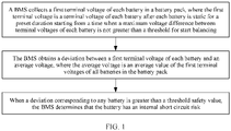
- the conventional technology provides a method for detecting an internal short circuit of the battery based on a voltage.
- a battery management system battery management system, BMS
- BMS battery management system
- a deviation between the terminal voltage and the average voltage is greater than a safety threshold, it is determined that the battery has a safety risk.
- a least square method is not required, and this reduces a requirement of the battery detection method for a hardware device.
- the terminal voltage of the battery is not only related to the battery internal resistance, but also easily affected by other various factors. As a result, accuracy of this method is relatively low, and misjudgment easily occurs.
- This application provides a battery detection method.
- a status parameter of a battery is input into a service system that includes a failure model obtained through training, to obtain a failure degree, and the failure degree is sent to a vehicle-mounted device and/or a terminal device, so that a failure risk of the battery can be accurately evaluated, and a loss caused by a battery failure can be reduced.
- embodiments of this application relate to massive applications of a neural network, for ease of understanding, the following first describes terms and concepts related to the neural network that may be used in embodiments of this application.
- the neural network may include a neuron.
- the neuron may be an operation unit that uses x s and an intercept of 1 as input.
- s 1, 2, ..., n, n is a natural number greater than 1
- W s represents a weight of x s
- both W and x are vectors
- b represents a bias of the neuron
- f indicates an activation function (activation function) of the neuron, where the activation function is used for introducing a non-linear characteristic into the neural network, to convert an input signal in the neuron into an output signal.
- the output signal of the activation function may be used as input to a next convolutional layer, and the activation function may be a sigmoid function.
- the neural network is a network constituted by connecting a plurality of single neurons together. To be specific, output of a neuron may be input to another neuron. Input to each neuron may be connected to a local receptive field of a previous layer to extract a feature of the local receptive field.
- the local receptive field may be a region including several neurons.
- the deep neural network (deep neural network, DNN) is also referred to as a multi-layer neural network, and may be understood as a neural network having a plurality of hidden layers. Based on locations of different layers, neural network layers inside the DNN may be classified into three types: an input layer, a hidden layer, and an output layer. Usually, the first layer is the input layer, the last layer is the output layer, and any layer between is the hidden layer. Layers are fully connected. To be specific, any neuron at an i th layer is necessarily connected to any neuron at an (i+1) th layer.
- a linear coefficient from the fourth neuron at the second layer to the second neuron at the third layer is defined as W 24 3 .
- the superscript 3 indicates a layer at which the coefficient is located, and the subscript corresponds to an output third-layer index 2 and an input second-layer index 4.
- a coefficient from a k th neuron at an (L-1) th layer to a j th neuron at a L th layer is defined as W jk L .
- the convolutional neural network (convolutional neural network, CNN) is a deep neural network with a convolutional structure.
- the convolutional neural network includes a feature extractor including a convolutional layer and a sub-sampling layer, and the feature extractor may be considered as a filter.
- the convolutional layer is a neuron layer that convolves an input signal in the convolutional neural network.
- At the convolutional layer of the convolutional neural network one neuron may be connected to only a part of neurons at a neighboring layer.
- a convolutional layer usually includes several feature planes, and each feature plane may include some neurons arranged in a rectangle. Neurons of a same feature plane share a weight, and the shared weight herein is a convolution kernel.
- Sharing a weight may be understood as image information is not extracted by location.
- the convolution kernel may be initialized in a form of a matrix of a random size.
- an appropriate weight may be obtained for the convolution kernel through learning.
- sharing the weight has advantages that connections between layers of the convolutional neural network are reduced, and a risk of overfitting is reduced.
- the recurrent neural network (recurrent neural network, RNN) is used to process sequence data.
- RNN recurrent neural network
- a conventional neural network model from an input layer to a hidden layer and then to an output layer, the layers are fully connected, but nodes at each layer are not connected.
- This common neural network resolves many problems, but is still incompetent on many other problems. For example, to predict a next word in a sentence, a previous word usually needs to be used, because adjacent words in the sentence are not independent.
- a reason why the RNN, short for the recurrent neural network, is named as such is that a current output of a sequence is also related to a previous output of the sequence.
- a specific representation form is that the network memorizes previous information and applies the previous information to calculation of the current output.
- the RNN can process sequence data of any length. Training of the RNN is the same as training of a conventional CNN or DNN.
- a predicted value of a current network and a target value as expected may be compared, and then a weight vector of each layer of the neural network is updated based on a difference between the predicted value and the target value (certainly, there is usually an initialization process before the first update, to be specific, parameters are preconfigured for all layers of the deep neural network). For example, if the predicted value of the network is large, the weight vector is adjusted to decrease the predicted value, and adjustment is continuously performed, until the deep neural network can predict the target value as expected or a value that is very close to the target value as expected.
- loss function loss function
- objective function object function
- the loss function and the objective function are important equations used to measure the difference between the predicted value and the target value.
- the loss function is used as an example.
- a larger output value (loss) of the loss function indicates a larger difference. Therefore, training of the deep neural network is a process of minimizing the loss as much as possible.
- a neural network may correct values of parameters in an initial neural network model by using an error back propagation (back propagation, BP) algorithm, so that a reconstruction error loss of the neural network model becomes increasingly smaller. Specifically, doing a forward pass from an input signal to an output generates an error loss, while the parameters of the neural network model are updated through back propagation of information about the error loss, to converge the error loss.
- the back propagation algorithm is a back propagation motion mainly dependent on the error loss, and is used for obtaining parameters of an optimal neural network model, for example, a weight matrix.
- a data collection device 260 is configured to collect training data.
- the training data may include a battery status parameter and a failure degree corresponding to the battery status parameter.
- the data collection device 260 After collecting the training data, the data collection device 260 stores the training data in a database 230.
- a training device 220 obtains a target model/rule 201 through training of the training data maintained in the database 230.
- the training device 220 processes an input battery status parameter and an original failure degree, and compares an output failure degree with the original failure degree until a difference between the failure degree output by the training device 220 and the original failure degree is less than a specific threshold. In this way, training of the target model/rule 101 is completed.
- the target model/rule 201 can be used to implement the battery detection method in embodiments of this application. In other words, after related preprocessing, the battery status parameter is input to the target model/rule 201, to obtain a result of the failure degree.
- the target model/rule 201 in embodiments of this application may be specifically a neural network. It should be noted that, during actual application, the training data maintained in the database 230 is not necessarily all collected by the data collection device 260, and may be received from another device. It should be further noted that the training device 220 may not necessarily train the target model/rule 201 completely based on the training data maintained in the database 230, or may obtain training data from a cloud or another place to perform model training. The foregoing description should not be construed as a limitation on embodiments of this application.
- the target model/rule 201 obtained through training by the training device 220 may be used in different systems or devices, for example, an execution device 210 shown in FIG. 2 .
- the execution device 210 may be a terminal, for example, a mobile phone terminal, a tablet computer, a laptop computer, an augmented reality (augmented reality, AR) AR/virtual reality (virtual reality, VR) terminal, or a vehicle-mounted terminal, or may be a server, a cloud, or the like.
- the execution device 210 is configured with an input/output (input/output, I/O) interface 212, to exchange data with an external device.
- I/O input/output
- a user may input data to the I/O interface 212 by using a client device 240.
- the input data may include a battery status parameter and a failure degree corresponding to the battery status parameter.
- a preprocessing module 213 and a preprocessing module 214 are configured to perform preprocessing based on input data (for example, a battery status parameter) received by the I/O interface 212.
- input data for example, a battery status parameter
- the execution device 210 may invoke data, code, and the like in a data storage system 250 for corresponding processing, and may also store data, instructions, and the like obtained through the corresponding processing into a data storage system 150.
- the I/O interface 212 returns a processing result, for example, the foregoing obtained failure degree, to the client device 240, to provide the processing result for the user.
- the training device 220 may generate corresponding target models/rules 201 for different targets or different tasks based on different training data.
- the corresponding target models/rules 201 may be used to implement the targets or complete the tasks, to provide a required result for the user.
- the user may manually provide the input data and the user may provide the input data on the I/O interface 212.
- the client device 240 may automatically send the input data to the I/O interface 212. If it is required that the client device 240 needs to obtain authorization from the user to automatically send the input data, the user may set corresponding permission on the client device 240.
- the user may view, on the client device 240, a result output by the execution device 210. Specifically, the result may be presented by display, sound, action, or the like.
- the client device 240 may also serve as a data collection end to collect, as new sample data, the input data into the I/O interface 212 and the output result from the I/O interface 212 that are shown in the figure, and store the new sample data into the database 230.
- the client device 140 may alternatively not perform collection, but the I/O interface 212 directly stores, as new sample data into the database 230, the input data into the I/O interface 212 and the output result from the I/O interface 212 that are shown in the figure.
- FIG. 2 is merely a schematic diagram of a system architecture according to an embodiment of this application.
- a location relationship between devices, components, modules, and the like shown in the figure does not constitute any limitation.
- the data storage system 250 is an external memory relative to the execution device 210, and in another case, the data storage system 250 may alternatively be disposed in the execution device 210.
- the target model/rule 201 is obtained through training by the training device 220.
- the target model/rule 201 may be a neural network in embodiments of this application.
- the neural network provided in embodiments of this application may be a CNN, a deep convolutional neural network (deep convolutional neural network, DCNN), a recurrent neural network (recurrent neural network, RNN), or the like.
- the convolutional neural network is a deep neural network with a convolutional structure, and is a deep learning (deep learning) architecture.
- the deep learning architecture is to perform multi-level learning at different abstract levels by using a machine learning algorithm.
- the CNN is a feed-forward (feed-forward) artificial neural network, and each neuron in the feed-forward artificial neural network can respond to an image input into the feed-forward artificial neural network.
- a convolutional neural network (CNN) 300 may include an input layer 310, a convolutional layer/pooling layer 320 (the pooling layer is optional), and a neural network layer 330.
- CNN convolutional neural network
- the convolutional layer/pooling layer 320 may include layers 321 to 326.
- the layer 321 is a convolutional layer
- the layer 322 is a pooling layer
- the layer 323 is a convolutional layer
- the layer 324 is a pooling layer
- the layer 325 is a convolutional layer
- the layer 326 is a pooling layer.
- the layer 321 and the layer 322 are convolutional layers
- the layer 323 is a pooling layer
- the layer 324 and the layer 325 are convolutional layers
- the layer 326 is a pooling layer.
- an output of a convolutional layer may be used as an input to a subsequent pooling layer, or may be used as an input to another convolutional layer to continue a convolution operation.
- the following uses the convolutional layer 321 as an example to describe an internal working principle of one convolutional layer.
- the convolutional layer 321 may include a plurality of convolution operators.
- the convolution operator is also referred to as a kernel.
- the convolution operator functions as a filter that extracts specific information from information such as an input battery status parameter.
- the convolution operator may essentially be a weight matrix, and the weight matrix is usually predefined.
- the weight matrix In a process of performing a convolution operation on a battery status parameter, the weight matrix usually processes data one by one in the input battery status parameter, to extract a specific feature from the battery status parameter.
- a size of the weight matrix should be related to a value of the battery status parameter. It should be noted that a depth dimension (depth dimension) of the weight matrix is the same as a depth dimension of the input battery status parameter.
- the weight matrix extends to an entire depth of the input battery status parameter. Therefore, a convolutional output of a single depth dimension is generated through convolution with a single weight matrix.
- a single weight matrix is not used, but a plurality of weight matrices with a same size (rows ⁇ columns), namely, a plurality of matrices of same dimensions, are applied.
- Outputs of weight matrices are stacked to form a depth dimension of a convolutional battery status parameter.
- the dimension herein may be understood as being determined based on the foregoing "plurality". Different weight matrices may be used to extract different features from the battery status parameter. For example, one weight matrix is used to extract discharge voltage data, another weight matrix is used to extract discharge current data, and still another weight matrix is used to extract charging temperature data.
- Weight values in these weight matrices need to be obtained through a lot of training during actual application.
- Each weight matrix formed by using the weight values obtained through training may be used to extract information from an input battery status parameter, to enable the convolutional neural network 300 to perform correct prediction.
- the convolutional neural network 300 When the convolutional neural network 300 has a plurality of convolutional layers, a relatively large quantity of general features are usually extracted at an initial convolutional layer (for example, 321).
- the general feature may also be referred to as a low-level feature.
- a feature extracted at a subsequent convolutional layer As the depth of the convolutional neural network 300 increases, a feature extracted at a subsequent convolutional layer (for example, 326) becomes more complex, for example, a high-level semantic feature. A feature with higher semantics is more applicable to a to-be-resolved problem.
- a pooling layer usually needs to be periodically introduced after a convolutional layer.
- one convolutional layer may be followed by one pooling layer, or a plurality of convolutional layers may be followed by one or more pooling layers.
- a unique purpose of the pooling layer is to reduce a space size of the battery status parameter.
- Neural network layer 330
- the convolutional neural network 300 After processing performed at the convolutional layer/pooling layer 320, the convolutional neural network 300 is not ready to output required output information. As described above, at the convolutional layer/pooling layer 320, only features are extracted, and parameters resulting from an input status parameter are reduced. However, to generate final output information (required class information or other related information), the convolutional neural network 300 needs to use the neural network layer 330 to generate an output of one required class or outputs of a group of required classes. Therefore, the neural network layer 330 may include a plurality of hidden layers (331 and 332 to 33n shown in FIG. 3 ) and an output layer 340. Parameters included in the plurality of hidden layers may be obtained through pre-training of related training data of a specific task type.
- the plurality of hidden layers are followed by the output layer 340, namely, the last layer of the entire convolutional neural network 300.
- the output layer 340 has a loss function similar to a categorical cross entropy, and the loss function is specifically used to calculate a prediction error.
- the convolutional neural network 300 shown in FIG. 3 is used only as an example of a convolutional neural network.
- the convolutional neural network may alternatively exist in a form of another network model.
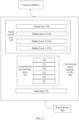
- FIG. 4 shows a hardware structure of a chip according to an embodiment of this application, and the chip includes a neural-network processing unit 40.
- the chip may be disposed in the execution device 210 shown in FIG. 2 , and is configured to complete calculation work of the calculation module 211.
- the chip may alternatively be disposed in the training device 220 shown in FIG. 2 , and is configured to complete training work of the training device 220 and output the target model/rule 201. All algorithms of the layers in the convolutional neural network shown in FIG. 3 may be implemented in the chip shown in FIG. 4 .
- the neural-network processing unit NPU 40 serves as a coprocessor, and may be disposed on a host central processing unit (central processing unit, CPU) (host CPU).
- the host CPU assigns a task.
- a core part of the NPU is an operation circuit 40, and a controller 404 controls the operation circuit 403 to extract data in a memory (a weight memory or an input memory) and perform an operation.
- the operation circuit 403 includes a plurality of process engines (process engines, PEs). In some implementations, the operation circuit 403 is a two-dimensional systolic array. The operation circuit 403 may alternatively be a one-dimensional systolic array or another electronic circuit capable of performing mathematical operations such as multiplication and addition. In some implementations, the operation circuit 403 is a general-purpose matrix processor.
- the operation circuit fetches corresponding data of the matrix B from a weight memory 402, and buffers the data on each PE in the operation circuit.
- the operation circuit fetches data of the matrix A from an input memory 401, to perform a matrix operation with the matrix B, and stores an obtained partial result or an obtained final result of the matrice into an accumulator (accumulator) 408.
- a vector calculation unit 407 may perform further processing on the output of the operation circuit, for example, vector multiplication, vector addition, exponential operation, logarithmic operation, and value comparison.
- the vector calculation unit 407 may be configured to perform network calculation, such as pooling (pooling), batch normalization (batch normalization), or local response normalization (local response normalization) at a non-convolutional/non-FC layer in a neural network.
- the vector calculation unit 407 can store a processed output vector in a unified memory 406.
- the vector calculation unit 407 may apply a non-linear function to the output of the operation circuit 403, for example, a vector of an accumulated value, to generate an activation value.
- the vector calculation unit 407 generates a normalized value, a combined value, or both.
- the processed output vector can be used as an activation input to the operation circuit 403, for example, for use in subsequent layers in the neural network.
- the unified memory 406 is configured to store input data and output data.
- a direct memory access controller (direct memory access controller, DMAC) 405 is used to transfer input data in an external memory to the input memory 401 and/or the unified memory 406, store weight data in the external memory into the weight memory 402, and store the data in the unified memory 406 into the external memory.
- DMAC direct memory access controller
- a bus interface unit (bus interface unit, BIU) 410 is configured to implement interaction between the host CPU, the DMAC, and an instruction fetch buffer 409 by using a bus.
- the instruction fetch buffer (instruction fetch buffer) 409 connected to the controller 404 is configured to store instructions used by the controller 404.
- the controller 404 is configured to invoke the instructions buffered in the instruction fetch buffer 409, to control a working process of an operation accelerator.
- Data herein may be described as description data according to an actual invention, for example, a detected vehicle speed, a distance to an obstacle, and the like.
- the unified memory 406, the input memory 401, the weight memory 402, and the instruction fetch buffer 409 each are an on-chip (On-Chip) memory.
- the external memory is a memory outside the NPU.
- the external memory may be a double data rate synchronous dynamic random access memory (double data rate synchronous dynamic random access memory, DDR SDRAM), a high bandwidth memory (high bandwidth memory, HBM), or another readable and writable memory.
- Operations at various layers in the convolutional neural network shown in FIG. 3 may be performed by the operation circuit 403 or the vector calculation unit 407.
- FIG. 5 is a schematic diagram of a battery detection method according to an embodiment of this application. As shown in FIG. 5 , the method includes steps S510 to S530. The following describes the three steps in detail.
- S510 A service system obtains a first battery status parameter of a battery.
- the service system may request, by sending a message to a vehicle-mounted system, the vehicle-mounted system to send the first battery status parameter of the battery, or the service system may invoke previously stored battery status data from a storage module.
- the vehicle-mounted system in this embodiment of this application may obtain a status parameter of a vehicle battery.
- the battery status parameter may include a driving mileage, a current battery SOC, a rechargeable battery temperature, a time, a discharge voltage, a discharge current, a battery model, and the like.
- S520 The service system determines a first failure degree based on the first battery status parameter and a failure model.
- the service system may display a detection result on the device, where the display form may be voice, text, or the like.
- the first failure degree indicates a failure degree of a current battery status
- the failure model is obtained through training based on a second battery status parameter and a second failure degree
- the second failure degree is a detected failure degree that is of a battery with a same specification and that corresponds to the second battery status parameter
- the battery status parameter includes at least one of the following parameters: a discharge voltage, a discharge current, and a charging temperature.
- a battery failure is a gradual process.
- the battery failure may be divided into three phases: early internal short circuit, middle internal short circuit, and later internal short circuit (thermal runaway).
- electrical features such as voltage and current
- a thermal feature temperature
- the three phases can be divided based on whether there is obvious self-generated heat and whether a separator failure temperature is reached.
- the three phases correspond to different failure degrees (such as 30% and 80%). Division of the battery failure phases is not limited in this application.
- the second battery status parameter may be obtained test data of a real battery of a same specification.
- the second failure degree may be a failure degree that corresponds to the second battery status parameter and that is actually recorded when the battery works normally, or may be a failure degree that is actually recorded when the battery fails.
- the test data may be test data obtained after a working condition simulation test is performed on a vehicle battery in a lab environment. For example, a discharge test is performed by setting a discharge temperature and a load of the battery, and test values such as a discharge voltage, a temperature, and an internal resistance of the battery are recorded.
- the second failure degree may be a failure degree recorded when the battery works normally in the simulation test, or may be failure degree data recorded when the battery fails in the simulation test.
- the failure degree of the battery is obtained by inputting the battery status parameter into the failure model, so that a battery failure risk can be accurately evaluated, to reduce personal injuries and property losses caused by thermal runaway of the battery.
- the failure model is obtained through algorithm training, and the process includes: inputting the second battery status parameter into an original model to obtain a third failure degree; adjusting a parameter of the original model, so that a deviation between the third failure degree and the second failure degree falls within a preset range; and using the original model that goes through the adjustment as the failure model.
- the foregoing failure model may be obtained from the system shown in FIG. 2 .
- the third failure degree obtained by using the original model is compared with the second failure degree that is of the battery and that is obtained through a real test, and the deviation between the third failure degree and the second failure degree is controlled within the preset range, so that a failure model that is more consistent with a real situation can be obtained, and accuracy of battery failure detection can be improved.
- the failure model in this embodiment of this application may be obtained by a remote service through training, or may be obtained from another device.
- the service system may further detect the failure degree of the battery based on the battery internal resistance.
- the determining the first failure degree based on the first battery status parameter and the failure model specifically includes: determining the battery internal resistance based on at least one parameter of the discharge voltage, the discharge current, and the charging temperature that are included in the first battery status parameter, where the battery internal resistance is used to determine the first failure degree.
- the battery internal resistance may be obtained by using a filtering method.
- the method can be achieved by the conventional technology, and details are not described in this embodiment of this application.
- the service system in this embodiment of this application may detect the battery after receiving the request message sent by a vehicle-mounted device and/or a terminal device. Specifically, before the determining the first failure degree based on the first battery status parameter and the failure model, the method further includes: receiving a third message, where the third message is used to request to detect the battery.
- the service system may obtain the third message before obtaining the first battery status parameter, or may obtain the third message before the service system determines the failure degree based on the status parameter and the failure model.
- the battery is detected after the request message sent by the vehicle-mounted device and/or the terminal device is received, so that a requirement of a user for detecting the battery at any time can be met, and user experience can be improved.
- the service system in this embodiment of this application may be disposed inside the vehicle.
- the service system in this embodiment of this application may be a remote service system independent of the vehicle or the another object.
- S530 The service system sends a first message, where the first message includes the first failure degree.
- the service system may send the first failure degree.
- the service system may send the first failure degree to the vehicle-mounted device of a vehicle to which the service system belongs, or may send the first failure degree to the terminal device (for example, a mobile phone or an application APP on the terminal device), or may send the message to a manufacturer service center, and share the message with another application module on a remote server.
- the service system may further send a reminder message.
- the service system may send a second message, where the second message is used to indicate that the battery has a failure risk.
- the second message may include a warning message, for example, reminding the user to repair or replace a battery, or include a message used to indicate the vehicle to take a coercive measure, for example, forcing the vehicle to decelerate or stop.
- the detection result is sent to the vehicle-mounted device, the terminal device, the mobile app, or the like, so that the user can determine a current battery failure status.
- the user can perform corresponding processing, for example, repair on the vehicle battery based on a requirement of the user.
- an alarm is sent when the failure degree exceeds a threshold, so that personal injuries and property safety of the user can be further ensured.
- the service system may also perform internal short circuit detection on the battery based on a preset time.
- the sending a first message specifically includes: sending the first message within a first preset time after the first battery status parameter is obtained.
- a preset time is set for the service system, so that the service system can send periodic battery detection information to the vehicle-mounted device or the terminal device, to improve user experience and reduce a loss caused by a battery failure.
- FIG. 6 is a schematic diagram of another battery detection method according to an embodiment of this application. As shown in FIG. 6 , the method includes steps S610 and S620. The following describes the two steps in detail.
- S610 Send a first message, where the first message is used to request to detect a battery.
- S620 Receive a second message, where the second message includes a first failure degree.
- the first failure degree is used to indicate a failure degree that is of the battery and that corresponds to a first battery status parameter
- the failure model is obtained through training based on a second battery status parameter and a second failure degree
- the second failure degree is a detected failure degree that is of a battery with a same specification and that corresponds to the second battery status parameter
- a battery status parameter includes at least one of the following parameters: a discharge voltage, a discharge current, and a charging temperature.
- the first message may be sent by a vehicle-mounted device, a terminal device, a mobile APP in the terminal device, or the like. This is not limited in this embodiment of this application.
- the vehicle-mounted device or the terminal device or the application APP may receive a reminder message. Specifically, the vehicle-mounted device or the terminal device or the application APP receives a third message, where the third message is used to indicate that the battery has a failure risk, and the third message is sent by a service system or a terminal device when the first failure degree is greater than or equal to a first threshold.
- the third message may be used to indicate the vehicle-mounted device to take a coercive measure, like forced deceleration or forced parking, or the third message may be further used to remind the user to repair or replace the battery as soon as possible.
- the vehicle-mounted device or the terminal device or the application APP may display the second message or the third message, for example, may display the second message or the third message on a display screen or by voice.
- the second message and/or the third message are/is displayed by using a display apparatus.
- the vehicle-mounted device may send the battery status parameter to the service system.
- the vehicle-mounted device sends the first battery status parameter, where the first battery status parameter includes at least one of the following parameters: the discharge voltage, the discharge current, and the charging temperature.
- FIG. 7 is a schematic diagram of a battery failure detection principle according to an embodiment of this application. As shown in FIG. 7 , the schematic diagram mainly includes a battery status parameter obtaining part, a failure model part, and a result output part.
- the battery status parameter obtaining part may include a battery status parameter and internal resistance estimation.
- a battery status parameter may include a discharge voltage, a discharge current, a current charging temperature, and another status parameter.
- the battery status parameter is sent by a vehicle-mounted system to a service system.
- the service system may obtain the status parameter by sending a request to the vehicle-mounted system, or optionally, the service system may invoke a stored battery status parameter from a storage module.
- the service system may input these status parameters to a failure model for battery detection.
- the battery status parameter input into the failure model may further include a battery internal resistance.
- the service system may obtain the current battery internal resistance according to a status estimation algorithm based on at least one of the foregoing battery status parameters.
- the status estimation algorithm may be a Kalman filtering, a Bayesian filtering, a hidden Markov model (hidden Markov model, HMM), or another algorithm to estimate the battery internal resistance.
- a method for obtaining a battery internal resistance value according to a status estimation algorithm can be achieved by the conventional technology, and details are not described in this application.
- the failure model part may include: obtaining test battery data.
- the test battery data herein may alternatively be the second battery status parameter in the foregoing embodiments of this application.
- the test battery data may be obtained test data of a real battery, or the test data may be test data obtained after a working condition simulation test is performed on a vehicle battery in a lab environment. For example, a discharge test is performed by setting a discharge temperature and a load of the battery, and test values such as the discharge voltage, the temperature, and the battery internal resistance are recorded.
- the failure model part may further include failure model estimation.
- an algorithm module of the service system may build, based on the foregoing test data, a failure model about the battery discharging status parameter according to algorithms such as a neural network, a long short-term memory (long short-term memory, LSTM), a random forest, and an HMM.
- the failure model may be obtained by using the neural network shown in FIG. 2 or FIG. 3 , and a battery failure degree threshold is obtained.
- the service system may output a battery detection result based on the battery status parameter and the failure model. Further, an alarm message may be sent based on the failure degree threshold.
- a battery failure degree is obtained by using a plurality of real-time battery status parameters including the battery internal resistance value and based on the failure model obtained through training, so that a battery failure risk can be accurately evaluated, and a loss caused by a battery failure can be reduced.
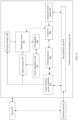
- FIG. 8 is a schematic diagram of a system architecture according to an embodiment of this application.
- the system architecture in this embodiment of this application may include a service system 810 and a vehicle-mounted system 820.
- the vehicle-mounted system 820 may collect battery-related data (including but not limited to a driving mileage, a current battery SOC, a battery temperature, a time, a discharge voltage, a discharge current, a battery model, and the like), and send the data to the service system over a specified protocol.
- the vehicle-mounted system 820 may include a data collection module, a data reporting module, a service request module, and a data display module.
- the service system 810 may include three layers.
- a first layer may include a data collection module, a data processing module, and a data storage module.
- a second layer may include a data analysis module, an algorithm module, and a failure model module.
- a third layer may include a battery failure detection application module.
- the service system 810 may have the following functions: After receiving the battery data, the service system parses a data packet, and then performs classified storage based on a vehicle identification number or another identifier. Based on the test battery data, the service system may generate a related failure model by using the algorithm module and based on the algorithm, and store the model in the failure model module.
- the service system may receive a detection request sent by a vehicle-mounted system, a terminal device, or another application, for example, a mobile phone application APP, and perform internal short circuit detection on a specified battery.
- the service system sends a detection result to a related vehicle-mounted system, terminal device (such as a mobile phone or a mobile APP), or another application service for data display.
- the data may be displayed by voice, text, or the like.
- the service system 810 may be disposed in a vehicle, or may be a remote service system independent of the vehicle. Disposing the service system in the remote service system independent of the vehicle can overcome a problem that a hardware requirement for the service system is relatively high.
- the battery failure detection application module may further include an information exchange module and an internal short circuit detection module.
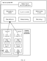
- FIG. 9 is a schematic diagram of interaction between modules according to an embodiment of this application.
- S910 The information exchange module receives a battery detection service request sent by a vehicle or a terminal device.
- S920 The internal short circuit detection module receives the service request.
- the internal short circuit detection module receives detection indication from the information exchange module, and invokes the data analysis module to obtain the battery data.
- the internal short circuit detection module may configure a battery discharge feature type that needs to be detected, for example, discharge voltage data, discharge current data, or charging temperature data.
- the data analysis module obtains a current battery status parameter.
- the service system may send a message to obtain latest battery data, or the service system may obtain stored battery status data from the storage module. It should be understood that the vehicle battery data stored in the storage module may include a plurality of types of data, but only several types of specific data may be required for internal short circuit detection.
- the data analysis module may extract a status parameter based on a battery status parameter type configured by the internal short circuit detection module, and extract only a status parameter required for battery detection.
- the service system may receive service requests of a plurality of objects.
- the data analysis module may first identify a vehicle that needs to be detected, and then obtain a battery status parameter of the battery of the vehicle.
- the data storage module may further obtain the battery internal resistance based on the obtained battery data, for example, at least one of the discharge voltage data, the discharge current data, and the discharge temperature data, by using the status estimation algorithm.
- the failure module receives the status parameter obtained by the data analysis module through processing.
- S950 The failure module performs detection based on the battery status parameter, obtains a battery failure degree in a current status, and returns the battery failure degree to the information exchange module.
- S960 The information exchange module returns the detection result to the vehicle, the terminal device, or the mobile phone APP.
- the information exchange module may further send an alarm message, where the alarm message may include a repair prompt, a deceleration prompt, a parking prompt, or the like.
- the information exchange module may further send the failure result to another related service for use, for example, a manufacturer service center.
- FIG. 10 is a schematic diagram of a battery detection apparatus according to an embodiment of this application.
- an apparatus 1000 includes a first obtaining module 1001, a first processing module 1002, and a first sending module 1003.
- the apparatus 1000 may be configured to implement a battery detection function in any one of the foregoing method embodiments.
- the apparatus 1000 may be a service system.
- the network element or network function may be a network element in a hardware device, may be a software function running on dedicated hardware, or may be a virtualized function instantiated on a platform (for example, a cloud platform).
- the apparatus 1000 may be used as a service system to detect a battery, and perform the steps performed by the service system in the foregoing method embodiments.
- the first receiving module 1001 and the first sending module 1003 may be configured to support the apparatus 1000 in performing communication, for example, performing sending/receiving actions in FIG. 5 and FIG. 6 as performed by the service system.
- the first processing module 1002 may be configured to support the apparatus 1000 in performing a processing action in the foregoing method, for example, performing a processing action in FIG. 5 or FIG. 6 as performed by the service system. Specifically, refer to the following descriptions.
- the first obtaining module 1001 is configured to obtain a first battery status parameter of a battery.
- the first processing module 1002 is configured to determine a first failure degree based on the first battery status parameter and a failure model, where the first failure degree is used to indicate a failure degree that is of the battery and that corresponds to the first battery status parameter, the failure model is obtained through training based on a second battery status parameter and a second failure degree, the second failure degree is a detected failure degree that is of a battery with a same specification and that corresponds to the second battery status parameter, and a battery status parameter includes at least one of the following parameters: a discharge voltage, a discharge current, and a charging temperature.
- the first sending module 1003 is configured to send a first message, where the first message includes the first failure degree.
- the processing module is specifically configured to: determine a battery internal resistance based on at least one parameter of the discharge voltage, the discharge current, and the charging temperature that are included in the first battery status parameter, where the battery internal resistance is used to determine the first failure degree.
- the first sending module is further configured to: send a second message when the first failure degree is greater than or equal to a preset first threshold, where the second message is used to indicate that the battery has a failure risk.
- the apparatus further includes a first receiving module, configured to receive a third message, where the third message is used to request to detect the battery.
- the first sending module is specifically configured to send the first message within a first preset time after the first battery status parameter is obtained.
- the first processing module is further configured to: input the second battery status parameter into an original model, to obtain a third failure degree; adjust a parameter of the original model, so that a deviation between the third failure degree and the second failure degree falls within a preset range; and use the original model that goes through the adjustment as the failure model.
- FIG. 11 is a schematic diagram of a battery detection apparatus according to an embodiment of this application.
- an apparatus 1100 includes a second sending module 1101 and a second receiving module 1102.
- the apparatus 1100 may be configured to implement a battery detection function in any one of the foregoing method embodiments.
- the apparatus 1100 may be used as a service system to detect a battery, and perform the steps performed by the vehicle-mounted device in the foregoing method embodiments.
- the second sending module 1101 and the second receiving module 1102 may be configured to support the apparatus 1100 in performing communication, for example, performing sending/receiving actions in FIG. 5 and FIG. 6 as performed by the vehicle-mounted device.
- the apparatus 1100 may further include a second processing module 1103.
- the processing module 1103 may be configured to support the apparatus 1100 in performing a processing action in the foregoing method, for example, performing a processing action in FIG. 2 and FIG. 6 as performed by the vehicle-mounted device. Specifically, refer to the following descriptions.
- the second sending module 1101 is configured to send a first message, where the first message is used to request the service system to detect a battery.
- the second receiving module 1102 is configured to receive a second message, where the second message includes a first failure degree, the first failure degree is used to indicate a failure degree that is of the battery and that corresponds to a first battery status parameter, a failure model is obtained through training based on a second battery status parameter and a second failure degree, the second failure degree is a detected failure degree that is of a battery with a same specification and that corresponds to the second battery status parameter, and a battery status parameter includes at least one of the following parameters: a discharge voltage, a discharge current, and a charging temperature.
- the second receiving module is further configured to receive a third message, where the third message is used to indicate that the battery has a failure risk, and the third message is sent by a service system or a terminal device when the first failure degree is greater than or equal to a first threshold.
- the apparatus further includes a second processing module, configured to take a coercive action based on the third message.
- the apparatus further includes a display module, configured to display the second message and/or the third message by using a display apparatus.
- the second sending module is further configured to send the first battery status parameter, where the first battery status parameter includes at least one of the following parameters: the discharge voltage, the discharge current, and the charging temperature.
- the disclosed system, apparatus, and method may be implemented in other manners.
- the foregoing apparatus embodiments are merely examples.
- division of the units is merely logical function division and may be other division during actual implementation.
- a plurality of units or components may be combined or integrated into another system, or some features may be ignored or not performed.
- the displayed or discussed mutual couplings or direct couplings or communication connections may be implemented by using some interfaces.
- the indirect couplings or communication connections between the apparatuses or units may be implemented in electronic, mechanical, or other forms.
- the units described as separate parts may or may not be physically separate, and parts displayed as units may or may not be physical units, may be located in one location, or may be distributed on a plurality of network units. Some or all of the units may be selected based on actual requirements to achieve the objective of the solutions of embodiments.
- the functions When the functions are implemented in a form of a software function unit and sold or used as an independent product, the functions may be stored in a computer-readable storage medium. Based on such an understanding, the technical solutions of this application essentially, or the part contributing to the conventional technology, or some of the technical solutions may be implemented in a form of a software product.
- the computer software product is stored in a storage medium, and includes several instructions for instructing a computer device (which may be a personal computer, a server, a network device, or the like) to perform all or some of the steps of the methods described in embodiments of this application.
- the foregoing storage medium includes any medium that can store program code, such as a USB flash drive, a removable hard disk, a read-only memory (read-only memory, ROM), a random access memory (random access memory, RAM), a magnetic disk, or a compact disc.
- program code such as a USB flash drive, a removable hard disk, a read-only memory (read-only memory, ROM), a random access memory (random access memory, RAM), a magnetic disk, or a compact disc.
Landscapes
- Physics & Mathematics (AREA)
- General Physics & Mathematics (AREA)
- Engineering & Computer Science (AREA)
- Power Engineering (AREA)
- Life Sciences & Earth Sciences (AREA)
- Sustainable Development (AREA)
- Sustainable Energy (AREA)
- Transportation (AREA)
- Mechanical Engineering (AREA)
- Secondary Cells (AREA)
- Charge And Discharge Circuits For Batteries Or The Like (AREA)
- Tests Of Electric Status Of Batteries (AREA)
Abstract
Description
- This application relates to the field of battery technologies, and more specifically, to a battery detection method and an apparatus, and a chip system.
- With a wide application of electric vehicles, safety accidents of lithium-ion power batteries occur frequently. Safety accidents of lithium-ion power batteries are usually characterized by sudden temperature rise, smoke, fire, and even explosion, with thermal runaway as the core. The safety accidents of lithium-ion power batteries on electric vehicles threaten the safety of people's lives and property, and seriously hinder the large-scale industrialization application of electric vehicles.
- The thermal runaway of power batteries is not an instant process, but a gradual process. If battery failures can be detected in an early stage, and preventive measures can be taken in advance or vehicle owners are warned to repair their vehicles as soon as possible, personal injuries and property losses caused by thermal runaway can be avoided. Therefore, how to accurately evaluate a battery failure degree and provide a countermeasure is an urgent problem to be resolved.
- This application provides a battery detection method and an apparatus. A status parameter of a battery is input into a service system that includes a failure model obtained through training, to obtain a failure degree, and the failure degree is sent to a vehicle-mounted device and/or a terminal device, so that a failure risk of the battery can be accurately evaluated, and a loss caused by a battery failure can be reduced.
- According to a first aspect, a battery detection method is provided. The method includes: obtaining a first battery status parameter of a battery; determining a first failure degree based on the first battery status parameter and a failure model, where the first failure degree is used to indicate a failure degree that is of the battery and that corresponds to the first battery status parameter, the failure model is obtained through training based on a second battery status parameter and a second failure degree, the second failure degree is a detected failure degree that is of a battery with a same specification and that corresponds to the second battery status parameter, and a battery status parameter includes at least one of the following parameters: a discharge voltage, a discharge current, and a charging temperature; and sending a first message, where the first message includes the first failure degree.
- The battery status parameter is input into a service system that includes the failure model obtained through training, to obtain the failure degree, and the failure degree is sent to a vehicle-mounted device and/or a terminal device, so that a failure risk of the battery can be accurately evaluated, and a loss caused by a battery failure can be reduced.
- With reference to the first aspect, in some implementations of the first aspect, the determining a first failure degree based on the first battery status parameter and a failure model specifically includes: determining a battery internal resistance based on at least one parameter of the discharge voltage, the discharge current, and the charging temperature that are included in the first battery status parameter, where the battery internal resistance is used to determine the first failure degree.
- A multi-dimensional battery status parameter including the battery internal resistance is input into the failure model, and the failure degree is obtained, so that accuracy of battery failure detection can be improved.
- With reference to the first aspect, in some implementations of the first aspect, when the first failure degree is greater than or equal to a preset first threshold, a second message is sent, where the second message is used to indicate that the battery has a failure risk.
- When a battery failure degree is greater than a preset threshold, a message is sent to remind a user that the battery has a failure risk, for example, to warn the user or to indicate a vehicle to take a coercive measure, so that personal injuries and property losses caused by the battery failure can be reduced.
- With reference to the first aspect, in some implementations of the first aspect, before the determining a first failure degree based on the first battery status parameter and a failure model, the method further includes: receiving a third message, where the third message is used to request to detect the battery.
- A request message is received and the battery is detected, so that user experience can be improved, and a requirement of the user for detecting the battery at any time can be met.
- With reference to the first aspect, in some implementations of the first aspect, the sending a first message specifically includes: sending the first message within a first preset time after the first battery status parameter is obtained.
- The battery is detected based on a preset time, for example, a specific time interval, and a detection result is sent, so that an effect of periodically detecting the battery can be achieved. This further improves user experience.
- With reference to the first aspect, in some implementations of the first aspect, the method further includes: inputting the second battery status parameter into an original model, to obtain a third failure degree; adjusting a parameter of the original model, so that a deviation between the third failure degree and the second failure degree falls within a preset range; and using the original model that goes through the adjustment as the failure model.
- Adjusting the failure model by using the original model can effectively improve accuracy of the failure model, and further improves accuracy of battery detection.
- According to a second aspect, a battery detection method is provided, where the method includes: sending a first message, where the first message is used to request to detect a battery; receiving a second message, where the second message includes a first failure degree, the first failure degree is used to indicate a failure degree that is of the battery and that corresponds to a first battery status parameter, a failure model is obtained through training based on a second battery status parameter and a second failure degree, the second failure degree is a detected failure degree that is of a battery with a same specification and that corresponds to the second battery status parameter, and a battery status parameter includes at least one of the following parameters: a discharge voltage, a discharge current, and a charging temperature.
- A request message used to request to detect the battery is sent to a service system, to obtain a failure degree based on the failure model, so that a battery failure risk can be accurately understood, and a loss caused by battery thermal runaway can be reduced. Optionally, the first message may be sent by a vehicle-mounted device, a terminal device, an application APP in the terminal device, or the like.
- With reference to the second aspect, in some implementations of the second aspect, a third message is received, where the third message is used to indicate that the battery has a failure risk, and the third message is sent by the service system or the terminal device when the first failure degree is greater than or equal to a first threshold.
- A warning message or an indication message that is sent when the battery failure degree exceeds a threshold is received, so that a measure, such as repair or replacement, can be taken on the battery in advance, and personal injuries and property losses caused by the battery failure can be reduced.
- With reference to the second aspect, in some implementations of the second aspect, the method further includes: taking a coercive action based on the third message.
- Taking a coercive measure, such as deceleration and parking, based on the message sent by the service system can effectively reduce personal injuries and property losses caused by the battery failure.
- With reference to the second aspect, in some implementations of the second aspect, the method further includes: displaying the second message and/or the third message by using a display apparatus.
- User experience can be improved by displaying the message sent by the service system.
- With reference to the second aspect, in some implementations of the second aspect, the method further includes: sending the first battery status parameter to the service system, where the first battery status parameter includes at least one of the following parameters: the discharge voltage, the discharge current, and the charging temperature.
- According to a third aspect, a battery detection apparatus is provided, where the apparatus includes: a first obtaining module, configured to obtain a first battery status parameter of a battery; a first processing module, configured to determine a first failure degree based on the first battery status parameter and a failure model, where the first failure degree is used to indicate a failure degree that is of the battery and that corresponds to the first battery status parameter, the failure model is obtained through training based on a second battery status parameter and a second failure degree, the second failure degree is a detected failure degree that is of a battery with a same specification and that corresponds to the second battery status parameter, and a battery status parameter includes at least one of the following parameters: a discharge voltage, a discharge current, and a charging temperature; and a first sending module, configured to send a first message, where the first message includes the first failure degree.
- With reference to the third aspect, in some implementations of the third aspect, the processing module is specifically configured to determine a battery internal resistance based on at least one parameter of the discharge voltage, the discharge current, and the charging temperature that are included in the first battery status parameter, where the battery internal resistance is used to determine the first failure degree.
- With reference to the third aspect, in some implementations of the third aspect, the first sending module is further configured to send a second message when the first failure degree is greater than or equal to a preset first threshold, where the second message is used to indicate that the battery has a failure risk.
- With reference to the third aspect, in some implementations of the third aspect, the apparatus further includes: a first receiving module, configured to receive a third message, where the third message is used to request to detect the battery.
- With reference to the third aspect, in some implementations of the third aspect, the first sending module is specifically configured to send the first message within a first preset time after the first battery status parameter is obtained.
- With reference to the third aspect, in some implementations of the third aspect, the first processing module is further configured to: input the second battery status parameter into an original model, to obtain a third failure degree; adjust a parameter of the original model, so that a deviation between the third failure degree and the second failure degree falls within a preset range; and use the original model that goes through the adjustment as the failure model.
- According to a fourth aspect, a battery detection apparatus is provided. The apparatus includes: a second sending module, configured to send a first message, where the first message is used to request to detect a battery; a second receiving module, configured to receive a second message, where the second message includes a first failure degree, the first failure degree is used to indicate a failure degree that is of the battery and that corresponds to a first battery status parameter, a failure model is obtained through training based on a second battery status parameter and a second failure degree, the second failure degree is a detected failure degree that is of a battery with a same specification and that corresponds to the second battery status parameter, and a battery status parameter includes at least one of the following parameters: a discharge voltage, a discharge current, and a charging temperature.
- With reference to the fourth aspect, in some implementations of the fourth aspect, the second receiving module is further configured to receive a third message, where the third message is used to indicate that the battery has a failure risk, and the third message is sent by a service system or a terminal device when the first failure degree is greater than or equal to a first threshold.
- With reference to the fourth aspect, in some implementations of the fourth aspect, the apparatus further includes: a second processing module, configured to take a coercion action based on the third message.
- With reference to the fourth aspect, in some implementations of the fourth aspect, the apparatus further includes: a display module, configured to display the second message and/or the third message by using a display apparatus.
- With reference to the fourth aspect, in some implementations of the fourth aspect, the second sending module is further configured to send the first battery status parameter, where the first battery status parameter includes at least one of the following parameters: the discharge voltage, the discharge current, and the charging temperature.
- According to a fifth aspect, a computer-readable storage medium is provided, including a computer program. When the computer program is run on a computer device, a processing unit in the computer device is enabled to perform the method in any one of the first aspect or the possible implementations of the first aspect.
- According to a sixth aspect, a computer-readable storage medium is provided, including a computer program. When the computer program is run on a computer device, a processing unit in the computer device is enabled to perform the method in any one of the second aspect or the possible implementations of the second aspect.
- According to a seventh aspect, a computer program product is provided, including a computer program. When the computer program is run on a computer device, a processing unit in the computer device is enabled to perform the method according to any one of the first aspect or the possible implementations of the first aspect.
- According to an eighth aspect, a computer program product is provided, including a computer program. When the computer program is run on a computer device, a processing unit in the computer device is enabled to perform the method according to any one of the second aspect or the possible implementations of the second aspect.
- According to a ninth aspect, a chip is provided, where the chip includes a processor and a memory, the memory is configured to store a computer program, and the processor is configured to invoke and run the computer program stored in the memory, to perform the method in any one of the first aspect or the possible implementations of the first aspect.
- According to a tenth aspect, a chip is provided, where the chip includes a processor and a memory, the memory is configured to store a computer program, and the processor is configured to invoke and run the computer program stored in the memory, to perform the method in any one of the second aspect or the possible implementations of the second aspect.
- According to an eleventh aspect, a chip system is provided. The chip system includes at least one processor, and when program instructions are executed in the at least one processor, the at least one processor is enabled to perform the battery detection method described above.
-
-
FIG. 1 is a schematic diagram of a battery detection method in the conventional technology; -
FIG. 2 is a schematic diagram of a structure of a system architecture according to an embodiment of this application; -
FIG. 3 is a schematic diagram of performing battery detection based on a convolutional neural network model according to an embodiment of this application; -
FIG. 4 is a schematic diagram of a hardware structure of a chip according to an embodiment of this application; -
FIG. 5 is a schematic diagram of a battery detection method according to an embodiment of this application; -
FIG. 6 is a schematic diagram of another battery detection method according to an embodiment of this application; -
FIG. 7 is a schematic diagram of a battery failure detection principle according to an embodiment of this application; -
FIG. 8 is a schematic diagram of a system architecture according to an embodiment of this application; -
FIG. 9 is a schematic diagram of interaction between modules according to an embodiment of this application; -
FIG. 10 is a schematic diagram of a battery detection apparatus according to an embodiment of this application; and -
FIG. 11 is a schematic diagram of another battery detection apparatus according to an embodiment of this application. - The following describes the technical solutions of this application with reference to the accompanying drawings.
- Embodiments of this application may be used for battery failure detection of an electric vehicle, or may be used for battery failure detection of various objects driven by a power battery, such as an electric bicycle.
- To determine a degree of an internal short circuit of a battery and reduce a loss caused by thermal runaway of the battery, the conventional technology provides a method for detecting an internal short circuit of the battery based on a voltage. As shown in
FIG. 1 , in the method, a battery management system (battery management system, BMS) collects a terminal voltage of each battery in a battery pack, and compares the terminal voltage with an average voltage. When a deviation between the terminal voltage and the average voltage is greater than a safety threshold, it is determined that the battery has a safety risk. In the method for detecting the battery by using the voltage in the conventional technology, a least square method is not required, and this reduces a requirement of the battery detection method for a hardware device. - However, in this method, the terminal voltage of the battery is not only related to the battery internal resistance, but also easily affected by other various factors. As a result, accuracy of this method is relatively low, and misjudgment easily occurs.
- This application provides a battery detection method. In this method, a status parameter of a battery is input into a service system that includes a failure model obtained through training, to obtain a failure degree, and the failure degree is sent to a vehicle-mounted device and/or a terminal device, so that a failure risk of the battery can be accurately evaluated, and a loss caused by a battery failure can be reduced.
- Because embodiments of this application relate to massive applications of a neural network, for ease of understanding, the following first describes terms and concepts related to the neural network that may be used in embodiments of this application.
- The neural network may include a neuron. The neuron may be an operation unit that uses xs and an intercept of 1 as input. Output of the operation unit may be as follows:

- Herein, s = 1, 2, ..., n, n is a natural number greater than 1, Ws represents a weight of xs, both W and x are vectors, b represents a bias of the neuron, and f indicates an activation function (activation function) of the neuron, where the activation function is used for introducing a non-linear characteristic into the neural network, to convert an input signal in the neuron into an output signal. The output signal of the activation function may be used as input to a next convolutional layer, and the activation function may be a sigmoid function. The neural network is a network constituted by connecting a plurality of single neurons together. To be specific, output of a neuron may be input to another neuron. Input to each neuron may be connected to a local receptive field of a previous layer to extract a feature of the local receptive field. The local receptive field may be a region including several neurons.
- The deep neural network (deep neural network, DNN) is also referred to as a multi-layer neural network, and may be understood as a neural network having a plurality of hidden layers. Based on locations of different layers, neural network layers inside the DNN may be classified into three types: an input layer, a hidden layer, and an output layer. Usually, the first layer is the input layer, the last layer is the output layer, and any layer between is the hidden layer. Layers are fully connected. To be specific, any neuron at an ith layer is necessarily connected to any neuron at an (i+1)th layer.
- Although the DNN seems complex, work at each layer of the DNN is actually not complex, and is simply represented as the following linear relationship expression:
y = α(W•x +b ), wherex is an input vector,y is an output vector,b is an offset vector, W is a weight matrix (also referred to as a coefficient), and α() is an activation function. At each layer, the output vectory is obtained by performing such a simple operation on the input vectorx . Because there are a large quantity of DNN layers, there are also a large quantity of coefficients W and offset vectorsb . Definitions of these parameters in the DNN are as follows: The coefficient W is used as an example. It is assumed that in a DNN having three layers, a linear coefficient from the fourth neuron at the second layer to the second neuron at the third layer is defined as
layer index 2 and an input second-layer index 4. - In conclusion, a coefficient from a kth neuron at an (L-1)th layer to a jth neuron at a Lth layer is defined as

- It should be noted that there is no parameter W at the input layer. In the deep neural network, more hidden layers make the network more capable of describing a complex case in the real world. Theoretically, a model with more parameters has higher complexity and a larger "capacity". It means that the model can complete a more complex learning task. Training of the deep neural network is a process of learning a weight matrix, and a final objective of the training is to obtain a weight matrix of all layers of a trained deep neural network (a weight matrix formed by vectors of many layers).
- The convolutional neural network (convolutional neural network, CNN) is a deep neural network with a convolutional structure. The convolutional neural network includes a feature extractor including a convolutional layer and a sub-sampling layer, and the feature extractor may be considered as a filter. The convolutional layer is a neuron layer that convolves an input signal in the convolutional neural network. At the convolutional layer of the convolutional neural network, one neuron may be connected to only a part of neurons at a neighboring layer. A convolutional layer usually includes several feature planes, and each feature plane may include some neurons arranged in a rectangle. Neurons of a same feature plane share a weight, and the shared weight herein is a convolution kernel. Sharing a weight may be understood as image information is not extracted by location. The convolution kernel may be initialized in a form of a matrix of a random size. In a training process of the convolutional neural network, an appropriate weight may be obtained for the convolution kernel through learning. In addition, sharing the weight has advantages that connections between layers of the convolutional neural network are reduced, and a risk of overfitting is reduced.
- The recurrent neural network (recurrent neural network, RNN) is used to process sequence data. In a conventional neural network model, from an input layer to a hidden layer and then to an output layer, the layers are fully connected, but nodes at each layer are not connected. This common neural network resolves many problems, but is still incompetent on many other problems. For example, to predict a next word in a sentence, a previous word usually needs to be used, because adjacent words in the sentence are not independent. A reason why the RNN, short for the recurrent neural network, is named as such is that a current output of a sequence is also related to a previous output of the sequence. A specific representation form is that the network memorizes previous information and applies the previous information to calculation of the current output. To be specific, nodes at the hidden layer are connected, and an input to the hidden layer not only includes an output of the input layer, but also includes an output of the hidden layer at a previous moment. Theoretically, the RNN can process sequence data of any length. Training of the RNN is the same as training of a conventional CNN or DNN.
- A reason why the recurrent neural network is required when there is the convolutional neural network is simple. In the convolutional neural network, there is a premise that elements are independent of each other, and input and output are also independent, such as a cat and a dog. However, many elements are interconnected in the real world. For example, stocks change over time. For another example, if a person says: "I like traveling, my most favorite place is Yunnan, and I will go to ... in the future if I have a chance." Herein, people should know that the ellipsis represents "Yunnan". This is because people can make an inference from a context, but how can a machine do this? The RNN emerges. The RNN is intended to make the machine capable of memorizing like a human. Therefore, an output of the RNN needs to depend on current input information and historical memorized information.
- In a process of training the deep neural network, to make output of the deep neural network as close as possible to what expects to be predicted, a predicted value of a current network and a target value as expected may be compared, and then a weight vector of each layer of the neural network is updated based on a difference between the predicted value and the target value (certainly, there is usually an initialization process before the first update, to be specific, parameters are preconfigured for all layers of the deep neural network). For example, if the predicted value of the network is large, the weight vector is adjusted to decrease the predicted value, and adjustment is continuously performed, until the deep neural network can predict the target value as expected or a value that is very close to the target value as expected. Therefore, "how to obtain, through comparison, the difference between the predicted value and the target value" needs to be predefined. This is a loss function (loss function) or an objective function (objective function). The loss function and the objective function are important equations used to measure the difference between the predicted value and the target value. The loss function is used as an example. A larger output value (loss) of the loss function indicates a larger difference. Therefore, training of the deep neural network is a process of minimizing the loss as much as possible.
- In a training process, a neural network may correct values of parameters in an initial neural network model by using an error back propagation (back propagation, BP) algorithm, so that a reconstruction error loss of the neural network model becomes increasingly smaller. Specifically, doing a forward pass from an input signal to an output generates an error loss, while the parameters of the neural network model are updated through back propagation of information about the error loss, to converge the error loss. The back propagation algorithm is a back propagation motion mainly dependent on the error loss, and is used for obtaining parameters of an optimal neural network model, for example, a weight matrix.
- Refer to
FIG. 2 . An embodiment of this application provides asystem architecture 200. InFIG. 2 , adata collection device 260 is configured to collect training data. For the battery detection method in embodiments of this application, the training data may include a battery status parameter and a failure degree corresponding to the battery status parameter. - After collecting the training data, the
data collection device 260 stores the training data in adatabase 230. Atraining device 220 obtains a target model/rule 201 through training of the training data maintained in thedatabase 230. - The following describes the target model/
rule 201 obtained by thetraining device 220 based on the training data. Thetraining device 220 processes an input battery status parameter and an original failure degree, and compares an output failure degree with the original failure degree until a difference between the failure degree output by thetraining device 220 and the original failure degree is less than a specific threshold. In this way, training of the target model/rule 101 is completed. - The target model/
rule 201 can be used to implement the battery detection method in embodiments of this application. In other words, after related preprocessing, the battery status parameter is input to the target model/rule 201, to obtain a result of the failure degree. The target model/rule 201 in embodiments of this application may be specifically a neural network. It should be noted that, during actual application, the training data maintained in thedatabase 230 is not necessarily all collected by thedata collection device 260, and may be received from another device. It should be further noted that thetraining device 220 may not necessarily train the target model/rule 201 completely based on the training data maintained in thedatabase 230, or may obtain training data from a cloud or another place to perform model training. The foregoing description should not be construed as a limitation on embodiments of this application. - The target model/
rule 201 obtained through training by thetraining device 220 may be used in different systems or devices, for example, anexecution device 210 shown inFIG. 2 . Theexecution device 210 may be a terminal, for example, a mobile phone terminal, a tablet computer, a laptop computer, an augmented reality (augmented reality, AR) AR/virtual reality (virtual reality, VR) terminal, or a vehicle-mounted terminal, or may be a server, a cloud, or the like. InFIG. 2 , theexecution device 210 is configured with an input/output (input/output, I/O)interface 212, to exchange data with an external device. A user may input data to the I/O interface 212 by using aclient device 240. In embodiments of this application, the input data may include a battery status parameter and a failure degree corresponding to the battery status parameter. - A
preprocessing module 213 and apreprocessing module 214 are configured to perform preprocessing based on input data (for example, a battery status parameter) received by the I/O interface 212. In embodiments of this application, there may be nopreprocessing module 213 or preprocessing module 214 (or there may be only one preprocessing module), and acalculation module 211 is directly used to process the input data. - In a process in which the
execution device 210 performs preprocessing on the input data or thecalculation module 211 of theexecution device 210 performs related processing such as calculation, theexecution device 210 may invoke data, code, and the like in adata storage system 250 for corresponding processing, and may also store data, instructions, and the like obtained through the corresponding processing into a data storage system 150. - Finally, the I/
O interface 212 returns a processing result, for example, the foregoing obtained failure degree, to theclient device 240, to provide the processing result for the user. - It should be noted that the
training device 220 may generate corresponding target models/rules 201 for different targets or different tasks based on different training data. The corresponding target models/rules 201 may be used to implement the targets or complete the tasks, to provide a required result for the user. - In a case shown in
FIG. 2 , the user may manually provide the input data and the user may provide the input data on the I/O interface 212. In another case, theclient device 240 may automatically send the input data to the I/O interface 212. If it is required that theclient device 240 needs to obtain authorization from the user to automatically send the input data, the user may set corresponding permission on theclient device 240. The user may view, on theclient device 240, a result output by theexecution device 210. Specifically, the result may be presented by display, sound, action, or the like. Theclient device 240 may also serve as a data collection end to collect, as new sample data, the input data into the I/O interface 212 and the output result from the I/O interface 212 that are shown in the figure, and store the new sample data into thedatabase 230. Certainly, the client device 140 may alternatively not perform collection, but the I/O interface 212 directly stores, as new sample data into thedatabase 230, the input data into the I/O interface 212 and the output result from the I/O interface 212 that are shown in the figure. - It should be noted that
FIG. 2 is merely a schematic diagram of a system architecture according to an embodiment of this application. A location relationship between devices, components, modules, and the like shown in the figure does not constitute any limitation. For example, inFIG. 2 , thedata storage system 250 is an external memory relative to theexecution device 210, and in another case, thedata storage system 250 may alternatively be disposed in theexecution device 210. - As shown in
FIG. 2 , the target model/rule 201 is obtained through training by thetraining device 220. The target model/rule 201 may be a neural network in embodiments of this application. Specifically, the neural network provided in embodiments of this application may be a CNN, a deep convolutional neural network (deep convolutional neural network, DCNN), a recurrent neural network (recurrent neural network, RNN), or the like. - Because the CNN is a very common neural network, a structure of the CNN is described below in detail with reference to
FIG. 3 . As described in the foregoing description of basic concepts, the convolutional neural network is a deep neural network with a convolutional structure, and is a deep learning (deep learning) architecture. The deep learning architecture is to perform multi-level learning at different abstract levels by using a machine learning algorithm. As a deep learning architecture, the CNN is a feed-forward (feed-forward) artificial neural network, and each neuron in the feed-forward artificial neural network can respond to an image input into the feed-forward artificial neural network. - As shown in
FIG. 3 , a convolutional neural network (CNN) 300 may include aninput layer 310, a convolutional layer/pooling layer 320 (the pooling layer is optional), and aneural network layer 330. The following describes the layers in detail. - As shown in
FIG. 3 , for example, the convolutional layer/pooling layer 320 may includelayers 321 to 326. For example, in an implementation, thelayer 321 is a convolutional layer, thelayer 322 is a pooling layer, thelayer 323 is a convolutional layer, thelayer 324 is a pooling layer, thelayer 325 is a convolutional layer, and thelayer 326 is a pooling layer. In another implementation, thelayer 321 and thelayer 322 are convolutional layers, thelayer 323 is a pooling layer, thelayer 324 and thelayer 325 are convolutional layers, and thelayer 326 is a pooling layer. To be specific, an output of a convolutional layer may be used as an input to a subsequent pooling layer, or may be used as an input to another convolutional layer to continue a convolution operation. - The following uses the
convolutional layer 321 as an example to describe an internal working principle of one convolutional layer. - The
convolutional layer 321 may include a plurality of convolution operators. The convolution operator is also referred to as a kernel. In battery detection, the convolution operator functions as a filter that extracts specific information from information such as an input battery status parameter. The convolution operator may essentially be a weight matrix, and the weight matrix is usually predefined. In a process of performing a convolution operation on a battery status parameter, the weight matrix usually processes data one by one in the input battery status parameter, to extract a specific feature from the battery status parameter. A size of the weight matrix should be related to a value of the battery status parameter. It should be noted that a depth dimension (depth dimension) of the weight matrix is the same as a depth dimension of the input battery status parameter. During a convolution operation, the weight matrix extends to an entire depth of the input battery status parameter. Therefore, a convolutional output of a single depth dimension is generated through convolution with a single weight matrix. However, in most cases, a single weight matrix is not used, but a plurality of weight matrices with a same size (rows × columns), namely, a plurality of matrices of same dimensions, are applied. Outputs of weight matrices are stacked to form a depth dimension of a convolutional battery status parameter. The dimension herein may be understood as being determined based on the foregoing "plurality". Different weight matrices may be used to extract different features from the battery status parameter. For example, one weight matrix is used to extract discharge voltage data, another weight matrix is used to extract discharge current data, and still another weight matrix is used to extract charging temperature data. - Weight values in these weight matrices need to be obtained through a lot of training during actual application. Each weight matrix formed by using the weight values obtained through training may be used to extract information from an input battery status parameter, to enable the convolutional
neural network 300 to perform correct prediction. - When the convolutional
neural network 300 has a plurality of convolutional layers, a relatively large quantity of general features are usually extracted at an initial convolutional layer (for example, 321). The general feature may also be referred to as a low-level feature. As the depth of the convolutionalneural network 300 increases, a feature extracted at a subsequent convolutional layer (for example, 326) becomes more complex, for example, a high-level semantic feature. A feature with higher semantics is more applicable to a to-be-resolved problem. - Because a quantity of training parameters usually needs to be reduced, a pooling layer usually needs to be periodically introduced after a convolutional layer. To be specific, for the
layers 321 to 326 in thelayer 320 shown inFIG. 3 , one convolutional layer may be followed by one pooling layer, or a plurality of convolutional layers may be followed by one or more pooling layers. In a battery detection process, a unique purpose of the pooling layer is to reduce a space size of the battery status parameter. - After processing performed at the convolutional layer/
pooling layer 320, the convolutionalneural network 300 is not ready to output required output information. As described above, at the convolutional layer/pooling layer 320, only features are extracted, and parameters resulting from an input status parameter are reduced. However, to generate final output information (required class information or other related information), the convolutionalneural network 300 needs to use theneural network layer 330 to generate an output of one required class or outputs of a group of required classes. Therefore, theneural network layer 330 may include a plurality of hidden layers (331 and 332 to 33n shown inFIG. 3 ) and anoutput layer 340. Parameters included in the plurality of hidden layers may be obtained through pre-training of related training data of a specific task type. - At the
neural network layer 330, the plurality of hidden layers are followed by theoutput layer 340, namely, the last layer of the entire convolutionalneural network 300. Theoutput layer 340 has a loss function similar to a categorical cross entropy, and the loss function is specifically used to calculate a prediction error. Once forward propagation (for example, propagation in a direction from 310 to 340 inFIG. 3 ) of the entire convolutionalneural network 300 is completed, back propagation (for example, propagation in a direction from 340 to 310 inFIG. 3 ) is started to update a weight value and a bias of each layer mentioned above, to reduce a loss of the convolutionalneural network 300 and an error between a result output by the convolutionalneural network 300 through the output layer and an ideal result. - It should be noted that the convolutional
neural network 300 shown inFIG. 3 is used only as an example of a convolutional neural network. In a specific application, the convolutional neural network may alternatively exist in a form of another network model. -
FIG. 4 shows a hardware structure of a chip according to an embodiment of this application, and the chip includes a neural-network processing unit 40. The chip may be disposed in theexecution device 210 shown inFIG. 2 , and is configured to complete calculation work of thecalculation module 211. The chip may alternatively be disposed in thetraining device 220 shown inFIG. 2 , and is configured to complete training work of thetraining device 220 and output the target model/rule 201. All algorithms of the layers in the convolutional neural network shown inFIG. 3 may be implemented in the chip shown inFIG. 4 . - The neural-network
processing unit NPU 40 serves as a coprocessor, and may be disposed on a host central processing unit (central processing unit, CPU) (host CPU). The host CPU assigns a task. A core part of the NPU is anoperation circuit 40, and acontroller 404 controls theoperation circuit 403 to extract data in a memory (a weight memory or an input memory) and perform an operation. - In some implementations, the
operation circuit 403 includes a plurality of process engines (process engines, PEs). In some implementations, theoperation circuit 403 is a two-dimensional systolic array. Theoperation circuit 403 may alternatively be a one-dimensional systolic array or another electronic circuit capable of performing mathematical operations such as multiplication and addition. In some implementations, theoperation circuit 403 is a general-purpose matrix processor. - For example, it is assumed that there is an input matrix A, a weight matrix B, and an output matrix C. The input matrix A in this embodiment of this application may be a matrix of battery status parameters, and the output matrix in this embodiment of this application may be a matrix of failure degrees. The operation circuit fetches corresponding data of the matrix B from a
weight memory 402, and buffers the data on each PE in the operation circuit. The operation circuit fetches data of the matrix A from aninput memory 401, to perform a matrix operation with the matrix B, and stores an obtained partial result or an obtained final result of the matrice into an accumulator (accumulator) 408. - A
vector calculation unit 407 may perform further processing on the output of the operation circuit, for example, vector multiplication, vector addition, exponential operation, logarithmic operation, and value comparison. For example, thevector calculation unit 407 may be configured to perform network calculation, such as pooling (pooling), batch normalization (batch normalization), or local response normalization (local response normalization) at a non-convolutional/non-FC layer in a neural network. - In some implementations, the
vector calculation unit 407 can store a processed output vector in aunified memory 406. For example, thevector calculation unit 407 may apply a non-linear function to the output of theoperation circuit 403, for example, a vector of an accumulated value, to generate an activation value. In some implementations, thevector calculation unit 407 generates a normalized value, a combined value, or both. In some implementations, the processed output vector can be used as an activation input to theoperation circuit 403, for example, for use in subsequent layers in the neural network. - The
unified memory 406 is configured to store input data and output data. - For weight data, a direct memory access controller (direct memory access controller, DMAC) 405 is used to transfer input data in an external memory to the
input memory 401 and/or theunified memory 406, store weight data in the external memory into theweight memory 402, and store the data in theunified memory 406 into the external memory. - A bus interface unit (bus interface unit, BIU) 410 is configured to implement interaction between the host CPU, the DMAC, and an instruction fetch
buffer 409 by using a bus. - The instruction fetch buffer (instruction fetch buffer) 409 connected to the
controller 404 is configured to store instructions used by thecontroller 404. - The
controller 404 is configured to invoke the instructions buffered in the instruction fetchbuffer 409, to control a working process of an operation accelerator. - Entry: Data herein may be described as description data according to an actual invention, for example, a detected vehicle speed, a distance to an obstacle, and the like.
- Usually, the
unified memory 406, theinput memory 401, theweight memory 402, and the instruction fetchbuffer 409 each are an on-chip (On-Chip) memory. The external memory is a memory outside the NPU. The external memory may be a double data rate synchronous dynamic random access memory (double data rate synchronous dynamic random access memory, DDR SDRAM), a high bandwidth memory (high bandwidth memory, HBM), or another readable and writable memory. - Operations at various layers in the convolutional neural network shown in
FIG. 3 may be performed by theoperation circuit 403 or thevector calculation unit 407. -
FIG. 5 is a schematic diagram of a battery detection method according to an embodiment of this application. As shown inFIG. 5 , the method includes steps S510 to S530. The following describes the three steps in detail. - S510: A service system obtains a first battery status parameter of a battery.
- Optionally, the service system may request, by sending a message to a vehicle-mounted system, the vehicle-mounted system to send the first battery status parameter of the battery, or the service system may invoke previously stored battery status data from a storage module.
- It should be understood that the vehicle-mounted system in this embodiment of this application may obtain a status parameter of a vehicle battery. The battery status parameter may include a driving mileage, a current battery SOC, a rechargeable battery temperature, a time, a discharge voltage, a discharge current, a battery model, and the like.
- S520: The service system determines a first failure degree based on the first battery status parameter and a failure model.
- It should be understood that, after obtaining the first failure degree, the service system may display a detection result on the device, where the display form may be voice, text, or the like.
- In an embodiment, the first failure degree indicates a failure degree of a current battery status, the failure model is obtained through training based on a second battery status parameter and a second failure degree, the second failure degree is a detected failure degree that is of a battery with a same specification and that corresponds to the second battery status parameter, and the battery status parameter includes at least one of the following parameters: a discharge voltage, a discharge current, and a charging temperature.
- It should be understood that a battery failure is a gradual process. For example, the battery failure may be divided into three phases: early internal short circuit, middle internal short circuit, and later internal short circuit (thermal runaway). In each phase, electrical features (such as voltage and current) and a thermal feature (temperature) of the battery are different. For example, in the later internal short circuit, the voltage is lost and heat is generated sharply. For lithium-ion batteries, the three phases can be divided based on whether there is obvious self-generated heat and whether a separator failure temperature is reached. The three phases correspond to different failure degrees (such as 30% and 80%). Division of the battery failure phases is not limited in this application.
- Optionally, the second battery status parameter may be obtained test data of a real battery of a same specification. In this case, based on battery failure degrees corresponding to different phases, the second failure degree may be a failure degree that corresponds to the second battery status parameter and that is actually recorded when the battery works normally, or may be a failure degree that is actually recorded when the battery fails. Alternatively, the test data may be test data obtained after a working condition simulation test is performed on a vehicle battery in a lab environment. For example, a discharge test is performed by setting a discharge temperature and a load of the battery, and test values such as a discharge voltage, a temperature, and an internal resistance of the battery are recorded. In this case, the second failure degree may be a failure degree recorded when the battery works normally in the simulation test, or may be failure degree data recorded when the battery fails in the simulation test.
- The failure degree of the battery is obtained by inputting the battery status parameter into the failure model, so that a battery failure risk can be accurately evaluated, to reduce personal injuries and property losses caused by thermal runaway of the battery.
- In an embodiment, the failure model is obtained through algorithm training, and the process includes: inputting the second battery status parameter into an original model to obtain a third failure degree; adjusting a parameter of the original model, so that a deviation between the third failure degree and the second failure degree falls within a preset range; and using the original model that goes through the adjustment as the failure model. Optionally, the foregoing failure model may be obtained from the system shown in
FIG. 2 . - It should be understood that, the third failure degree obtained by using the original model is compared with the second failure degree that is of the battery and that is obtained through a real test, and the deviation between the third failure degree and the second failure degree is controlled within the preset range, so that a failure model that is more consistent with a real situation can be obtained, and accuracy of battery failure detection can be improved.
- Optionally, the failure model in this embodiment of this application may be obtained by a remote service through training, or may be obtained from another device.
- Optionally, in addition to the parameters included in the first battery status parameter, the service system may further detect the failure degree of the battery based on the battery internal resistance. Specifically, the determining the first failure degree based on the first battery status parameter and the failure model specifically includes: determining the battery internal resistance based on at least one parameter of the discharge voltage, the discharge current, and the charging temperature that are included in the first battery status parameter, where the battery internal resistance is used to determine the first failure degree.
- It should be understood that the battery internal resistance may be obtained by using a filtering method. The method can be achieved by the conventional technology, and details are not described in this embodiment of this application.
- Optionally, the service system in this embodiment of this application may detect the battery after receiving the request message sent by a vehicle-mounted device and/or a terminal device. Specifically, before the determining the first failure degree based on the first battery status parameter and the failure model, the method further includes: receiving a third message, where the third message is used to request to detect the battery. Optionally, the service system may obtain the third message before obtaining the first battery status parameter, or may obtain the third message before the service system determines the failure degree based on the status parameter and the failure model.
- The battery is detected after the request message sent by the vehicle-mounted device and/or the terminal device is received, so that a requirement of a user for detecting the battery at any time can be met, and user experience can be improved.
- It should be understood that the service system in this embodiment of this application may be disposed inside the vehicle. Alternatively, when the vehicle or another object using a power battery cannot meet a hardware requirement, optionally, the service system in this embodiment of this application may be a remote service system independent of the vehicle or the another object.
- S530: The service system sends a first message, where the first message includes the first failure degree.
- In an embodiment, after obtaining the first failure degree, the service system may send the first failure degree. Optionally, the service system may send the first failure degree to the vehicle-mounted device of a vehicle to which the service system belongs, or may send the first failure degree to the terminal device (for example, a mobile phone or an application APP on the terminal device), or may send the message to a manufacturer service center, and share the message with another application module on a remote server.
- In an embodiment, the service system may further send a reminder message. Specifically, when the first failure degree is greater than or equal to a preset first threshold, the service system may send a second message, where the second message is used to indicate that the battery has a failure risk. Optionally, the second message may include a warning message, for example, reminding the user to repair or replace a battery, or include a message used to indicate the vehicle to take a coercive measure, for example, forcing the vehicle to decelerate or stop.
- The detection result is sent to the vehicle-mounted device, the terminal device, the mobile app, or the like, so that the user can determine a current battery failure status. The user can perform corresponding processing, for example, repair on the vehicle battery based on a requirement of the user. In addition, an alarm is sent when the failure degree exceeds a threshold, so that personal injuries and property safety of the user can be further ensured.
- Optionally, the service system may also perform internal short circuit detection on the battery based on a preset time. Specifically, the sending a first message specifically includes: sending the first message within a first preset time after the first battery status parameter is obtained.
- A preset time is set for the service system, so that the service system can send periodic battery detection information to the vehicle-mounted device or the terminal device, to improve user experience and reduce a loss caused by a battery failure.
-
FIG. 6 is a schematic diagram of another battery detection method according to an embodiment of this application. As shown inFIG. 6 , the method includes steps S610 and S620. The following describes the two steps in detail. - S610: Send a first message, where the first message is used to request to detect a battery.
- S620: Receive a second message, where the second message includes a first failure degree.
- In an embodiment, the first failure degree is used to indicate a failure degree that is of the battery and that corresponds to a first battery status parameter, the failure model is obtained through training based on a second battery status parameter and a second failure degree, the second failure degree is a detected failure degree that is of a battery with a same specification and that corresponds to the second battery status parameter, and a battery status parameter includes at least one of the following parameters: a discharge voltage, a discharge current, and a charging temperature.
- Optionally, the first message may be sent by a vehicle-mounted device, a terminal device, a mobile APP in the terminal device, or the like. This is not limited in this embodiment of this application.
- In an embodiment, the vehicle-mounted device or the terminal device or the application APP may receive a reminder message. Specifically, the vehicle-mounted device or the terminal device or the application APP receives a third message, where the third message is used to indicate that the battery has a failure risk, and the third message is sent by a service system or a terminal device when the first failure degree is greater than or equal to a first threshold.
- Optionally, when the first message is sent by the vehicle-mounted device, the third message may be used to indicate the vehicle-mounted device to take a coercive measure, like forced deceleration or forced parking, or the third message may be further used to remind the user to repair or replace the battery as soon as possible.
- Optionally, the vehicle-mounted device or the terminal device or the application APP may display the second message or the third message, for example, may display the second message or the third message on a display screen or by voice. Specifically, the second message and/or the third message are/is displayed by using a display apparatus.
- Optionally, before requesting the service system to perform battery detection, the vehicle-mounted device may send the battery status parameter to the service system. Specifically, the vehicle-mounted device sends the first battery status parameter, where the first battery status parameter includes at least one of the following parameters: the discharge voltage, the discharge current, and the charging temperature.
- Other steps are the same as those in
FIG. 5 , and details are not described again in this embodiment of this application. -
FIG. 7 is a schematic diagram of a battery failure detection principle according to an embodiment of this application. As shown inFIG. 7 , the schematic diagram mainly includes a battery status parameter obtaining part, a failure model part, and a result output part. - The battery status parameter obtaining part may include a battery status parameter and internal resistance estimation. A battery status parameter may include a discharge voltage, a discharge current, a current charging temperature, and another status parameter. The battery status parameter is sent by a vehicle-mounted system to a service system. The service system may obtain the status parameter by sending a request to the vehicle-mounted system, or optionally, the service system may invoke a stored battery status parameter from a storage module. The service system may input these status parameters to a failure model for battery detection. Optionally, the battery status parameter input into the failure model may further include a battery internal resistance. Specifically, the service system may obtain the current battery internal resistance according to a status estimation algorithm based on at least one of the foregoing battery status parameters. The status estimation algorithm may be a Kalman filtering, a Bayesian filtering, a hidden Markov model (hidden Markov model, HMM), or another algorithm to estimate the battery internal resistance. A method for obtaining a battery internal resistance value according to a status estimation algorithm can be achieved by the conventional technology, and details are not described in this application.
- The failure model part may include: obtaining test battery data. The test battery data herein may alternatively be the second battery status parameter in the foregoing embodiments of this application. The test battery data may be obtained test data of a real battery, or the test data may be test data obtained after a working condition simulation test is performed on a vehicle battery in a lab environment. For example, a discharge test is performed by setting a discharge temperature and a load of the battery, and test values such as the discharge voltage, the temperature, and the battery internal resistance are recorded. The failure model part may further include failure model estimation. Specifically, an algorithm module of the service system may build, based on the foregoing test data, a failure model about the battery discharging status parameter according to algorithms such as a neural network, a long short-term memory (long short-term memory, LSTM), a random forest, and an HMM. For example, the failure model may be obtained by using the neural network shown in
FIG. 2 orFIG. 3 , and a battery failure degree threshold is obtained. - Then, the service system may output a battery detection result based on the battery status parameter and the failure model. Further, an alarm message may be sent based on the failure degree threshold.
- A battery failure degree is obtained by using a plurality of real-time battery status parameters including the battery internal resistance value and based on the failure model obtained through training, so that a battery failure risk can be accurately evaluated, and a loss caused by a battery failure can be reduced.
-
FIG. 8 is a schematic diagram of a system architecture according to an embodiment of this application. As shown inFIG. 8 , the system architecture in this embodiment of this application may include aservice system 810 and a vehicle-mountedsystem 820. - The vehicle-mounted
system 820 may collect battery-related data (including but not limited to a driving mileage, a current battery SOC, a battery temperature, a time, a discharge voltage, a discharge current, a battery model, and the like), and send the data to the service system over a specified protocol. The vehicle-mountedsystem 820 may include a data collection module, a data reporting module, a service request module, and a data display module. - The
service system 810 may include three layers. A first layer may include a data collection module, a data processing module, and a data storage module. A second layer may include a data analysis module, an algorithm module, and a failure model module. A third layer may include a battery failure detection application module. - The
service system 810 may have the following functions: After receiving the battery data, the service system parses a data packet, and then performs classified storage based on a vehicle identification number or another identifier. Based on the test battery data, the service system may generate a related failure model by using the algorithm module and based on the algorithm, and store the model in the failure model module. The service system may receive a detection request sent by a vehicle-mounted system, a terminal device, or another application, for example, a mobile phone application APP, and perform internal short circuit detection on a specified battery. The service system sends a detection result to a related vehicle-mounted system, terminal device (such as a mobile phone or a mobile APP), or another application service for data display. Optionally, the data may be displayed by voice, text, or the like. Optionally, theservice system 810 may be disposed in a vehicle, or may be a remote service system independent of the vehicle. Disposing the service system in the remote service system independent of the vehicle can overcome a problem that a hardware requirement for the service system is relatively high. - The battery failure detection application module may further include an information exchange module and an internal short circuit detection module.
-
FIG. 9 is a schematic diagram of interaction between modules according to an embodiment of this application. As shown inFIG. 9 , S910: The information exchange module receives a battery detection service request sent by a vehicle or a terminal device. S920: The internal short circuit detection module receives the service request. - S930: The internal short circuit detection module receives detection indication from the information exchange module, and invokes the data analysis module to obtain the battery data. The internal short circuit detection module may configure a battery discharge feature type that needs to be detected, for example, discharge voltage data, discharge current data, or charging temperature data. The data analysis module obtains a current battery status parameter. Optionally, the service system may send a message to obtain latest battery data, or the service system may obtain stored battery status data from the storage module. It should be understood that the vehicle battery data stored in the storage module may include a plurality of types of data, but only several types of specific data may be required for internal short circuit detection. In this case, the data analysis module may extract a status parameter based on a battery status parameter type configured by the internal short circuit detection module, and extract only a status parameter required for battery detection. Optionally, when the service system is independent of the vehicle-mounted system, the service system may receive service requests of a plurality of objects. In this case, the data analysis module may first identify a vehicle that needs to be detected, and then obtain a battery status parameter of the battery of the vehicle. Optionally, when the detected battery data includes the battery internal resistance, the data storage module may further obtain the battery internal resistance based on the obtained battery data, for example, at least one of the discharge voltage data, the discharge current data, and the discharge temperature data, by using the status estimation algorithm.
- S940: The failure module receives the status parameter obtained by the data analysis module through processing. S950: The failure module performs detection based on the battery status parameter, obtains a battery failure degree in a current status, and returns the battery failure degree to the information exchange module. S960: The information exchange module returns the detection result to the vehicle, the terminal device, or the mobile phone APP. Optionally, when the failure degree in the detection result exceeds the degree threshold, the information exchange module may further send an alarm message, where the alarm message may include a repair prompt, a deceleration prompt, a parking prompt, or the like. Optionally, the information exchange module may further send the failure result to another related service for use, for example, a manufacturer service center.
-
FIG. 10 is a schematic diagram of a battery detection apparatus according to an embodiment of this application. As shown inFIG. 10 , an apparatus 1000 includes a first obtainingmodule 1001, afirst processing module 1002, and afirst sending module 1003. The apparatus 1000 may be configured to implement a battery detection function in any one of the foregoing method embodiments. For example, the apparatus 1000 may be a service system. The network element or network function may be a network element in a hardware device, may be a software function running on dedicated hardware, or may be a virtualized function instantiated on a platform (for example, a cloud platform). - The apparatus 1000 may be used as a service system to detect a battery, and perform the steps performed by the service system in the foregoing method embodiments. The
first receiving module 1001 and thefirst sending module 1003 may be configured to support the apparatus 1000 in performing communication, for example, performing sending/receiving actions inFIG. 5 and FIG. 6 as performed by the service system. Thefirst processing module 1002 may be configured to support the apparatus 1000 in performing a processing action in the foregoing method, for example, performing a processing action inFIG. 5 or FIG. 6 as performed by the service system. Specifically, refer to the following descriptions. - The first obtaining
module 1001 is configured to obtain a first battery status parameter of a battery. Thefirst processing module 1002 is configured to determine a first failure degree based on the first battery status parameter and a failure model, where the first failure degree is used to indicate a failure degree that is of the battery and that corresponds to the first battery status parameter, the failure model is obtained through training based on a second battery status parameter and a second failure degree, the second failure degree is a detected failure degree that is of a battery with a same specification and that corresponds to the second battery status parameter, and a battery status parameter includes at least one of the following parameters: a discharge voltage, a discharge current, and a charging temperature. Thefirst sending module 1003 is configured to send a first message, where the first message includes the first failure degree. - Optionally, the processing module is specifically configured to: determine a battery internal resistance based on at least one parameter of the discharge voltage, the discharge current, and the charging temperature that are included in the first battery status parameter, where the battery internal resistance is used to determine the first failure degree.
- Optionally, the first sending module is further configured to: send a second message when the first failure degree is greater than or equal to a preset first threshold, where the second message is used to indicate that the battery has a failure risk.
- Optionally, the apparatus further includes a first receiving module, configured to receive a third message, where the third message is used to request to detect the battery.
- Optionally, the first sending module is specifically configured to send the first message within a first preset time after the first battery status parameter is obtained.
- Optionally, the first processing module is further configured to: input the second battery status parameter into an original model, to obtain a third failure degree; adjust a parameter of the original model, so that a deviation between the third failure degree and the second failure degree falls within a preset range; and use the original model that goes through the adjustment as the failure model.
-
FIG. 11 is a schematic diagram of a battery detection apparatus according to an embodiment of this application. As shown inFIG. 11 , an apparatus 1100 includes asecond sending module 1101 and asecond receiving module 1102. The apparatus 1100 may be configured to implement a battery detection function in any one of the foregoing method embodiments. - The apparatus 1100 may be used as a service system to detect a battery, and perform the steps performed by the vehicle-mounted device in the foregoing method embodiments. The
second sending module 1101 and thesecond receiving module 1102 may be configured to support the apparatus 1100 in performing communication, for example, performing sending/receiving actions inFIG. 5 and FIG. 6 as performed by the vehicle-mounted device. Optionally, the apparatus 1100 may further include a second processing module 1103. The processing module 1103 may be configured to support the apparatus 1100 in performing a processing action in the foregoing method, for example, performing a processing action inFIG. 2 andFIG. 6 as performed by the vehicle-mounted device. Specifically, refer to the following descriptions. - The
second sending module 1101 is configured to send a first message, where the first message is used to request the service system to detect a battery. Thesecond receiving module 1102 is configured to receive a second message, where the second message includes a first failure degree, the first failure degree is used to indicate a failure degree that is of the battery and that corresponds to a first battery status parameter, a failure model is obtained through training based on a second battery status parameter and a second failure degree, the second failure degree is a detected failure degree that is of a battery with a same specification and that corresponds to the second battery status parameter, and a battery status parameter includes at least one of the following parameters: a discharge voltage, a discharge current, and a charging temperature. - Optionally, the second receiving module is further configured to receive a third message, where the third message is used to indicate that the battery has a failure risk, and the third message is sent by a service system or a terminal device when the first failure degree is greater than or equal to a first threshold.
- Optionally, the apparatus further includes a second processing module, configured to take a coercive action based on the third message.
- Optionally, the apparatus further includes a display module, configured to display the second message and/or the third message by using a display apparatus.
- Optionally, the second sending module is further configured to send the first battery status parameter, where the first battery status parameter includes at least one of the following parameters: the discharge voltage, the discharge current, and the charging temperature.
- A person of ordinary skill in the art may be aware that, the units and algorithm steps in the examples described with reference to embodiments disclosed in this specification may be implemented by electronic hardware or a combination of computer software and electronic hardware. Whether the functions are performed by hardware or software depends on particular applications and design constraint conditions of the technical solutions. A person skilled in the art may use different methods to implement the described functions for each particular application, but it should not be considered that the implementation goes beyond the scope of this application.
- It may be clearly understood by a person skilled in the art that, for the purpose of convenient and brief description, for a detailed working process of the foregoing system, apparatus, and unit, refer to a corresponding process in the foregoing method embodiments, and details are not described herein again.
- In the several embodiments provided in this application, it should be understood that the disclosed system, apparatus, and method may be implemented in other manners. For example, the foregoing apparatus embodiments are merely examples. For example, division of the units is merely logical function division and may be other division during actual implementation. For example, a plurality of units or components may be combined or integrated into another system, or some features may be ignored or not performed. In addition, the displayed or discussed mutual couplings or direct couplings or communication connections may be implemented by using some interfaces. The indirect couplings or communication connections between the apparatuses or units may be implemented in electronic, mechanical, or other forms.
- The units described as separate parts may or may not be physically separate, and parts displayed as units may or may not be physical units, may be located in one location, or may be distributed on a plurality of network units. Some or all of the units may be selected based on actual requirements to achieve the objective of the solutions of embodiments.
- In addition, functional units in embodiments of this application may be integrated into one processing unit, each of the units may exist alone physically, or two or more units are integrated into one unit.
- When the functions are implemented in a form of a software function unit and sold or used as an independent product, the functions may be stored in a computer-readable storage medium. Based on such an understanding, the technical solutions of this application essentially, or the part contributing to the conventional technology, or some of the technical solutions may be implemented in a form of a software product. The computer software product is stored in a storage medium, and includes several instructions for instructing a computer device (which may be a personal computer, a server, a network device, or the like) to perform all or some of the steps of the methods described in embodiments of this application. The foregoing storage medium includes any medium that can store program code, such as a USB flash drive, a removable hard disk, a read-only memory (read-only memory, ROM), a random access memory (random access memory, RAM), a magnetic disk, or a compact disc.
- The foregoing descriptions are merely specific implementations of this application, but are not intended to limit the protection scope of this application. Any variation or replacement readily figured out by a person skilled in the art within the technical scope disclosed in this application shall fall within the protection scope of this application. Therefore, the protection scope of this application shall be subject to the protection scope of the claims.
Claims (23)
- A battery detection method, wherein the method comprises:obtaining a first battery status parameter of a battery;determining a first failure degree based on the first battery status parameter and a failure model, wherein the first failure degree is used to indicate a failure degree that is of the battery and that corresponds to the first battery status parameter, the failure model is obtained through training based on a second battery status parameter and a second failure degree, the second failure degree is a detected failure degree that is of a battery with a same specification and that corresponds to the second battery status parameter, and a battery status parameter comprises at least one of the following parameters:a discharge voltage, a discharge current, and a charging temperature; andsending a first message, wherein the first message comprises the first failure degree.
- The method according to claim 1, wherein the determining a first failure degree based on the first battery status parameter and a failure model specifically comprises:
determining a battery internal resistance based on at least one parameter of the discharge voltage, the discharge current, and the charging temperature that are comprised in the first battery status parameter, wherein the battery internal resistance is used to determine the first failure degree. - The method according to claim 1 or 2, wherein the method further comprises:
sending a second message when the first failure degree is greater than or equal to a preset first threshold, wherein the second message is used to indicate that the battery has a failure risk. - The method according to any one of claims 1 to 3, wherein before the determining a first failure degree based on the first battery status parameter and a failure model, the method further comprises:
receiving a third message, wherein the third message is used to request to detect the battery. - The method according to any one of claims 1 to 4, wherein the sending a first message specifically comprises:
sending the first message within a first preset time after the first battery status parameter is obtained. - The method according to any one of claims 1 to 5, wherein the method further comprises:inputting the second battery status parameter into an original model, to obtain a third failure degree;adjusting a parameter of the original model, so that a deviation between the third failure degree and the second failure degree falls within a preset range; andusing the original model that goes through the adjustment as the failure model.
- A battery detection method, wherein the method comprises:sending a first message, wherein the first message is used to request to detect a battery; andreceiving a second message, wherein the second message comprises a first failure degree, the first failure degree is used to indicate a failure degree that is of the battery and that corresponds to a first battery status parameter, a failure model is obtained through training based on a second battery status parameter and a second failure degree, the second failure degree is a detected failure degree that is of a battery with a same specification and that corresponds to the second battery status parameter, and a battery status parameter comprises at least one of the following parameters:
a discharge voltage, a discharge current, and a charging temperature. - The method according to claim 7, wherein the method further comprises:
receiving a third message, wherein the third message is used to indicate that the battery has a failure risk, and the third message is sent by a service system or a terminal device when the first failure degree is greater than or equal to a first threshold. - The method according to claim 8, wherein the method further comprises: taking a coercive action based on the third message.
- The method according to claim 9, wherein the method further comprises:
displaying the second message and/or the third message by using a display apparatus. - The method according to any one of claims 7 to 10, wherein the method further comprises:
sending the first battery status parameter, wherein the first battery status parameter comprises at least one of the following parameters: the discharge voltage, the discharge current, and the charging temperature. - A battery detection apparatus, comprising:a first obtaining module, configured to obtain a first battery status parameter of a battery;a first processing module, configured to determine a first failure degree based on the first battery status parameter and a failure model, wherein the first failure degree is used to indicate a failure degree that is of the battery and that corresponds to the first battery status parameter, the failure model is obtained through training based on a second battery status parameter and a second failure degree, the second failure degree is a detected failure degree that is of a battery with a same specification and that corresponds to the second battery status parameter, and a battery status parameter comprises at least one of the following parameters:a discharge voltage, a discharge current, and a charging temperature; anda first sending module, configured to send a first message, wherein the first message comprises the first failure degree.
- The apparatus according to claim 12, wherein the processing module is specifically configured to:
determine a battery internal resistance based on at least one parameter of the discharge voltage, the discharge current, and the charging temperature that are comprised in the first battery status parameter, wherein the battery internal resistance is used to determine the first failure degree. - The apparatus according to claim 12 or 13, wherein the first sending module is further configured to:
send a second message when the first failure degree is greater than or equal to a preset first threshold, wherein the second message is used to indicate that the battery has a failure risk. - The apparatus according to any one of claims 12 to 14, wherein the apparatus further comprises:
a first receiving module, configured to receive a third message, wherein the third message is used to request to detect the battery. - The apparatus according to any one of claims 12 to 15, wherein the first sending module is specifically configured to:
send the first message within a first preset time after the first battery status parameter is obtained. - The apparatus according to any one of claims 12 to 16, wherein the first processing module is further configured to:input the second battery status parameter into an original model, to obtain a third failure degree;adjust a parameter of the original model, so that a deviation between the third failure degree and the second failure degree falls within a preset range; anduse the original model that goes through the adjustment as the failure model.
- A battery detection apparatus, comprising:a second sending module, configured to send a first message, wherein the first message is used to request to detect a battery; anda second receiving module, configured to receive a second message, wherein the second message comprises a first failure degree, the first failure degree is used to indicate a failure degree that is of the battery and that corresponds to a first battery status parameter, a failure model is obtained through training based on a second battery status parameter and a second failure degree, the second failure degree is a detected failure degree that is of a battery with a same specification and that corresponds to the second battery status parameter, and a battery status parameter comprises at least one of the following parameters:
a discharge voltage, a discharge current, and a charging temperature. - The apparatus according to claim 18, wherein the second receiving module is further configured to:
receive a third message, wherein the third message is used to indicate that the battery has a failure risk, and the third message is sent by a service system or a terminal device when the first failure degree is greater than or equal to a first threshold. - The apparatus according to claim 19, wherein the apparatus further comprises:
a second processing module, configured to take a coercive action based on the third message. - The apparatus according to claim 20, wherein the apparatus further comprises:
a display module, configured to display the second message and/or the third message by using a display apparatus. - The apparatus according to any one of claims 18 to 21, wherein the second sending module is further configured to:
send the first battery status parameter, wherein the first battery status parameter comprises at least one of the following parameters: the discharge voltage, the discharge current, and the charging temperature. - A chip system, wherein the chip system comprises at least one processor, and when program instructions are executed in the at least one processor, the at least one processor is enabled to perform the battery detection method according to any one of claims 1 to 11.
Applications Claiming Priority (1)
| Application Number | Priority Date | Filing Date | Title |
|---|---|---|---|
| PCT/CN2020/086781 WO2021212496A1 (en) | 2020-04-24 | 2020-04-24 | Battery detection method and apparatus |
Publications (3)
| Publication Number | Publication Date |
|---|---|
| EP4130766A1 true EP4130766A1 (en) | 2023-02-08 |
| EP4130766A4 EP4130766A4 (en) | 2023-06-07 |
| EP4130766B1 EP4130766B1 (en) | 2025-08-20 |
Family
ID=75291261
Family Applications (1)
| Application Number | Title | Priority Date | Filing Date |
|---|---|---|---|
| EP20932184.3A Active EP4130766B1 (en) | 2020-04-24 | 2020-04-24 | Battery detection method and apparatus |
Country Status (5)
| Country | Link |
|---|---|
| EP (1) | EP4130766B1 (en) |
| JP (1) | JP2023522468A (en) |
| KR (1) | KR102869261B1 (en) |
| CN (1) | CN112639495A (en) |
| WO (1) | WO2021212496A1 (en) |
Families Citing this family (26)
| Publication number | Priority date | Publication date | Assignee | Title |
|---|---|---|---|---|
| CN113343633B (en) * | 2021-06-10 | 2022-04-26 | 上海交通大学 | Thermal runaway fault classification and risk prediction method and system for power lithium battery |
| CN114417948B (en) * | 2021-06-18 | 2025-12-30 | 重庆长安汽车股份有限公司 | A method for predicting battery thermal runaway based on neural networks |
| CN113884924B (en) * | 2021-11-16 | 2024-07-30 | 中国科学院电工研究所 | Lithium ion battery internal short circuit diagnosis method and system based on convolutional neural network |
| CN114547966B (en) * | 2022-01-10 | 2024-09-24 | 浙江大学 | Fault vulnerability assessment method for neural network accelerator based on hardware feature information |
| CN114683964B (en) * | 2022-03-29 | 2024-04-26 | 北京芯虹科技有限责任公司 | A method for determining battery status information and charging device |
| CN114839556B (en) * | 2022-05-10 | 2024-10-11 | 中国第一汽车股份有限公司 | Power battery abnormality detection method and device, storage medium and electronic device |
| CN114970703B (en) * | 2022-05-18 | 2025-02-07 | 广东电网有限责任公司广州供电局 | A method for identifying voltage levels of power equipment with dynamic adjustment of neural network levels |
| CN115184808B (en) * | 2022-07-05 | 2024-06-18 | 东莞新能安科技有限公司 | Battery thermal runaway risk detection method, device, equipment and computer storage medium |
| CN115097315A (en) * | 2022-07-11 | 2022-09-23 | 易事特集团股份有限公司 | Lithium battery SOC prediction method |
| CN115320385B (en) * | 2022-07-28 | 2024-04-30 | 重庆金康赛力斯新能源汽车设计院有限公司 | Thermal runaway early warning method, device, equipment and storage medium for vehicle battery |
| CN115308629B (en) * | 2022-08-23 | 2024-08-13 | 中国第一汽车股份有限公司 | Method and device for testing battery performance, storage medium and electronic equipment |
| CN115372830B (en) * | 2022-08-29 | 2025-08-05 | 上海机动车检测认证技术研究中心有限公司 | A method for assessing thermal runaway risk of power batteries |
| CN115859579B (en) * | 2022-11-18 | 2025-10-21 | 宁德时代新能源科技股份有限公司 | Fault assessment method, device, storage medium and electrical device |
| CN115902646B (en) * | 2023-01-06 | 2023-06-13 | 中国电力科学研究院有限公司 | An energy storage battery fault identification method and system |
| CN116299038B (en) * | 2023-02-13 | 2024-04-05 | 上海玫克生储能科技有限公司 | Method, system, equipment and storage medium for detecting micro short circuit of battery cell |
| CN116520153B (en) * | 2023-04-26 | 2024-03-26 | 广东博龙能源科技有限公司 | Early warning protection method and system for thermal runaway of lithium battery |
| CN116714437B (en) * | 2023-06-01 | 2024-03-26 | 西华大学 | Hydrogen fuel cell vehicle safety monitoring system and monitoring method based on big data |
| KR102877564B1 (en) * | 2023-10-17 | 2025-10-28 | 삼성전자주식회사 | Method and apparatus for training short circuit detection model |
| CN117686916B (en) * | 2023-12-12 | 2024-08-30 | 中通维易科技服务有限公司 | Laboratory digital management system |
| KR102895371B1 (en) * | 2024-03-12 | 2025-12-04 | 주식회사 배러머신 | Method for managing battery even with limited data by using decoder |
| JPWO2025197105A1 (en) * | 2024-03-22 | 2025-09-25 | ||
| KR20250177227A (en) * | 2024-06-14 | 2025-12-23 | 주식회사 엘지에너지솔루션 | Apparatus for diagnosing battery and operating method thereof |
| KR102820060B1 (en) * | 2024-08-16 | 2025-06-12 | 주식회사 피엠그로우 | Method for providing battery pack safety service |
| CN120044426A (en) * | 2025-02-14 | 2025-05-27 | 苏州星德胜智能电气有限公司 | Battery pack fault analysis method and system |
| CN119821200B (en) * | 2025-03-18 | 2025-05-27 | 深圳市皇驰科技有限公司 | Charging safety detection method, device, computer equipment and storage medium |
| CN120577721B (en) * | 2025-08-05 | 2025-09-26 | 江苏电子信息职业学院 | Battery multi-physical-quantity performance test and intelligent diagnosis method, system, device and storage medium |
Family Cites Families (32)
| Publication number | Priority date | Publication date | Assignee | Title |
|---|---|---|---|---|
| JP4457781B2 (en) * | 2004-07-02 | 2010-04-28 | 新神戸電機株式会社 | Deterioration degree estimation method and deterioration degree estimation apparatus |
| KR20070051916A (en) * | 2004-08-25 | 2007-05-18 | 닛본 덴끼 가부시끼가이샤 | Internal impedance detection device, internal impedance detection method, deterioration detection device and deterioration detection method |
| JP2007216707A (en) * | 2006-02-14 | 2007-08-30 | Fujitsu Ten Ltd | Device and method for determining battery degradation |
| JP2008058278A (en) * | 2006-09-04 | 2008-03-13 | Toyota Motor Corp | Secondary battery internal state estimation device, secondary battery internal state estimation method, program, and recording medium |
| JP5633227B2 (en) * | 2009-10-14 | 2014-12-03 | ソニー株式会社 | Battery pack and battery pack deterioration detection method |
| JP5343168B2 (en) * | 2010-06-24 | 2013-11-13 | パナソニック株式会社 | Method and system for obtaining the degree of battery degradation |
| JP5558941B2 (en) * | 2010-06-30 | 2014-07-23 | 三洋電機株式会社 | How to detect battery internal resistance |
| JP5278508B2 (en) * | 2011-07-25 | 2013-09-04 | 横河電機株式会社 | Battery degradation determination apparatus and method |
| WO2014097490A1 (en) * | 2012-12-21 | 2014-06-26 | 株式会社日立製作所 | Lithium-ion secondary battery module, and device and method for assessing remaining life of same |
| US9846203B2 (en) * | 2013-04-30 | 2017-12-19 | Mitsubishi Electric Corporation | Storage battery state detection apparatus and storage battery state detection method |
| JP6370902B2 (en) * | 2014-06-24 | 2018-08-15 | 株式会社東芝 | Deterioration control apparatus and method for storage battery system |
| KR102357351B1 (en) * | 2015-01-07 | 2022-01-28 | 삼성전자주식회사 | Device and apparatus to estimate state of batter pakc including the plurality of battery cells |
| JP6593769B2 (en) * | 2015-03-09 | 2019-10-23 | 中国電力株式会社 | Storage battery remaining life estimation method, storage battery check date determination method, storage battery remaining life estimation device, and storage battery remaining life estimation system |
| CN104777431B (en) * | 2015-04-30 | 2018-07-17 | 大连楼兰科技股份有限公司 | Vehicle battery deterioration detection equipment and method based on OBD interface |
| CN204758795U (en) * | 2015-06-01 | 2015-11-11 | 上海市松江区青少年活动中心 | Rechargeable battery failure state detector |
| CN106680720B (en) * | 2015-11-11 | 2019-07-02 | 中国移动通信集团公司 | Vehicle battery failure warning system and method based on Internet of Vehicles |
| CN107329088B (en) * | 2016-04-29 | 2021-05-14 | 株式会社日立制作所 | Battery state of health diagnosis device and method |
| CN105866551B (en) * | 2016-06-27 | 2018-11-27 | 上海电气钠硫储能技术有限公司 | A kind of sodium-sulphur battery internal resistance detection method |
| KR102726191B1 (en) * | 2016-10-05 | 2024-11-06 | 삼성전자주식회사 | Device and method to estimate state of battery |
| CN106772099A (en) * | 2017-01-23 | 2017-05-31 | 合肥国轩高科动力能源有限公司 | A method for estimating the deterioration degree of power lithium battery |
| JP2019079629A (en) * | 2017-10-20 | 2019-05-23 | 本田技研工業株式会社 | Power source system |
| CN108562855B (en) * | 2017-12-18 | 2020-02-07 | 清华大学 | Method and device for detecting short circuit in battery and computer readable storage medium |
| TWI835767B (en) * | 2017-12-27 | 2024-03-21 | 日商F S R股份有限公司 | secondary battery |
| CN108258338A (en) * | 2017-12-29 | 2018-07-06 | 江苏博强新能源科技股份有限公司 | Battery management system and method |
| WO2019138286A1 (en) * | 2018-01-11 | 2019-07-18 | 株式会社半導体エネルギー研究所 | Abormality detection device for secondary battery, abnormality detection method, and program |
| WO2019181727A1 (en) * | 2018-03-20 | 2019-09-26 | 株式会社Gsユアサ | Abnormal factor determination device, deterioration determination device, computer program, deterioration determination method and abnormal factor determination method |
| CA3095272C (en) * | 2018-03-28 | 2021-11-30 | Toyo System Co., Ltd. | Degradation state determination device and degradation state determination method |
| JP7446990B2 (en) * | 2018-04-06 | 2024-03-11 | 株式会社半導体エネルギー研究所 | Method for estimating state of charge of power storage device and state of charge estimation system for power storage device |
| JPWO2020012720A1 (en) * | 2018-07-10 | 2021-08-12 | 住友電気工業株式会社 | Secondary battery parameter estimation device, secondary battery parameter estimation method and program |
| JP7085428B2 (en) * | 2018-07-10 | 2022-06-16 | 株式会社半導体エネルギー研究所 | Battery protection circuit, power storage device, and electrical equipment |
| JP7249155B2 (en) * | 2018-09-20 | 2023-03-30 | 積水化学工業株式会社 | Storage battery management device and storage battery management method |
| CN110861531A (en) * | 2019-11-27 | 2020-03-06 | 四川野马汽车股份有限公司 | Power battery failure early warning system and method |
-
2020
- 2020-04-24 EP EP20932184.3A patent/EP4130766B1/en active Active
- 2020-04-24 WO PCT/CN2020/086781 patent/WO2021212496A1/en not_active Ceased
- 2020-04-24 KR KR1020227040401A patent/KR102869261B1/en active Active
- 2020-04-24 JP JP2022564504A patent/JP2023522468A/en active Pending
- 2020-04-24 CN CN202080004896.4A patent/CN112639495A/en active Pending
Also Published As
| Publication number | Publication date |
|---|---|
| CN112639495A (en) | 2021-04-09 |
| JP2023522468A (en) | 2023-05-30 |
| KR102869261B1 (en) | 2025-10-14 |
| EP4130766A4 (en) | 2023-06-07 |
| EP4130766B1 (en) | 2025-08-20 |
| KR20230006855A (en) | 2023-01-11 |
| WO2021212496A1 (en) | 2021-10-28 |
Similar Documents
| Publication | Publication Date | Title |
|---|---|---|
| EP4130766B1 (en) | Battery detection method and apparatus | |
| Jiao et al. | A yolov3-based learning strategy for real-time uav-based forest fire detection | |
| EP4679327A1 (en) | Model training method, power prediction method, and device | |
| CN111797970B (en) | Method and device for training neural network | |
| WO2022143903A1 (en) | Safety evaluation method and system for vehicle battery, and device and readable storage medium | |
| CN113821875A (en) | A real-time prediction method and system for intelligent vehicle faults based on device-cloud collaboration | |
| CN118364432B (en) | Sensor data fusion method, device and storage medium based on graph neural network | |
| US20230385603A1 (en) | Neural architecture search system and search method | |
| US20240217388A1 (en) | Probabilistic modelling of electric vehicle charging and driving usage behavior with hidden markov model-based clustering | |
| CN117237349A (en) | Thermal runaway protection methods, devices, equipment and storage media for battery management systems | |
| CN112381015A (en) | Fatigue degree identification method, device and equipment | |
| WO2023184188A1 (en) | Method and apparatus for fault monitoring of neural network model in autonomous driving system | |
| CN115729796A (en) | Abnormal operation analysis method based on artificial intelligence and big data application system | |
| CN118331239A (en) | Cloud computing-based new energy automobile remote diagnosis method and system | |
| CN119418426A (en) | A flight information monitoring system and method for unmanned aerial vehicle | |
| Qu et al. | Towards efficient traffic crash detection based on macro and micro data fusion on expressways: A digital twin framework | |
| CN112132335A (en) | Method, device, device and storage medium for predicting traffic accident | |
| CN118296447A (en) | Vehicle danger early warning grading method, device and storage medium | |
| Yang et al. | Method of predicting braking intention using LSTM-CNN-Attention with hyperparameters optimized by genetic algorithm | |
| KR102676906B1 (en) | Method for monitoring wind power generator based on artificial intelligence using sound, vibration information and drond shooting photo | |
| CN116050480B (en) | Battery data processing methods, machine learning model training methods and equipment | |
| CN119212002A (en) | A method for pre-offloading computation in MEC vehicle networks based on trajectory prediction | |
| CN115514787A (en) | Intelligent unmanned aerial vehicle assisted decision-making planning method and device for Internet of Vehicles environment | |
| CN118823976B (en) | Alarm suppression method and device based on BMS battery management system | |
| CN121658207A (en) | A data processing method and device |
Legal Events
| Date | Code | Title | Description |
|---|---|---|---|
| STAA | Information on the status of an ep patent application or granted ep patent |
Free format text: STATUS: THE INTERNATIONAL PUBLICATION HAS BEEN MADE |
|
| PUAI | Public reference made under article 153(3) epc to a published international application that has entered the european phase |
Free format text: ORIGINAL CODE: 0009012 |
|
| STAA | Information on the status of an ep patent application or granted ep patent |
Free format text: STATUS: REQUEST FOR EXAMINATION WAS MADE |
|
| 17P | Request for examination filed |
Effective date: 20221103 |
|
| AK | Designated contracting states |
Kind code of ref document: A1 Designated state(s): AL AT BE BG CH CY CZ DE DK EE ES FI FR GB GR HR HU IE IS IT LI LT LU LV MC MK MT NL NO PL PT RO RS SE SI SK SM TR |
|
| A4 | Supplementary search report drawn up and despatched |
Effective date: 20230509 |
|
| RIC1 | Information provided on ipc code assigned before grant |
Ipc: G01R 31/392 20190101ALI20230502BHEP Ipc: G01R 31/367 20190101ALI20230502BHEP Ipc: G01R 31/36 20200101AFI20230502BHEP |
|
| DAV | Request for validation of the european patent (deleted) | ||
| DAX | Request for extension of the european patent (deleted) | ||
| RAP1 | Party data changed (applicant data changed or rights of an application transferred) |
Owner name: SHENZHEN YINWANG INTELLIGENTTECHNOLOGIES CO., LTD. |
|
| GRAP | Despatch of communication of intention to grant a patent |
Free format text: ORIGINAL CODE: EPIDOSNIGR1 |
|
| STAA | Information on the status of an ep patent application or granted ep patent |
Free format text: STATUS: GRANT OF PATENT IS INTENDED |
|
| RIC1 | Information provided on ipc code assigned before grant |
Ipc: B60L 58/16 20190101ALI20250318BHEP Ipc: B60L 58/10 20190101ALI20250318BHEP Ipc: B60L 3/00 20190101ALI20250318BHEP Ipc: G01R 31/392 20190101ALI20250318BHEP Ipc: G01R 31/367 20190101ALI20250318BHEP Ipc: G01R 31/36 20200101AFI20250318BHEP |
|
| INTG | Intention to grant announced |
Effective date: 20250327 |
|
| GRAS | Grant fee paid |
Free format text: ORIGINAL CODE: EPIDOSNIGR3 |
|
| GRAA | (expected) grant |
Free format text: ORIGINAL CODE: 0009210 |
|
| STAA | Information on the status of an ep patent application or granted ep patent |
Free format text: STATUS: THE PATENT HAS BEEN GRANTED |
|
| AK | Designated contracting states |
Kind code of ref document: B1 Designated state(s): AL AT BE BG CH CY CZ DE DK EE ES FI FR GB GR HR HU IE IS IT LI LT LU LV MC MK MT NL NO PL PT RO RS SE SI SK SM TR |
|
| REG | Reference to a national code |
Ref country code: GB Ref legal event code: FG4D |
|
| REG | Reference to a national code |
Ref country code: CH Ref legal event code: EP |
|
| REG | Reference to a national code |
Ref country code: IE Ref legal event code: FG4D |
|
| REG | Reference to a national code |
Ref country code: DE Ref legal event code: R096 Ref document number: 602020057213 Country of ref document: DE |
|
| REG | Reference to a national code |
Ref country code: NL Ref legal event code: MP Effective date: 20250820 |
|
| PG25 | Lapsed in a contracting state [announced via postgrant information from national office to epo] |
Ref country code: IS Free format text: LAPSE BECAUSE OF FAILURE TO SUBMIT A TRANSLATION OF THE DESCRIPTION OR TO PAY THE FEE WITHIN THE PRESCRIBED TIME-LIMIT Effective date: 20251220 |
|
| PG25 | Lapsed in a contracting state [announced via postgrant information from national office to epo] |
Ref country code: NO Free format text: LAPSE BECAUSE OF FAILURE TO SUBMIT A TRANSLATION OF THE DESCRIPTION OR TO PAY THE FEE WITHIN THE PRESCRIBED TIME-LIMIT Effective date: 20251120 |
|
| REG | Reference to a national code |
Ref country code: LT Ref legal event code: MG9D |
|
| PG25 | Lapsed in a contracting state [announced via postgrant information from national office to epo] |
Ref country code: PT Free format text: LAPSE BECAUSE OF FAILURE TO SUBMIT A TRANSLATION OF THE DESCRIPTION OR TO PAY THE FEE WITHIN THE PRESCRIBED TIME-LIMIT Effective date: 20251222 |
|
| PG25 | Lapsed in a contracting state [announced via postgrant information from national office to epo] |
Ref country code: FI Free format text: LAPSE BECAUSE OF FAILURE TO SUBMIT A TRANSLATION OF THE DESCRIPTION OR TO PAY THE FEE WITHIN THE PRESCRIBED TIME-LIMIT Effective date: 20250820 |
|
| PG25 | Lapsed in a contracting state [announced via postgrant information from national office to epo] |
Ref country code: HR Free format text: LAPSE BECAUSE OF FAILURE TO SUBMIT A TRANSLATION OF THE DESCRIPTION OR TO PAY THE FEE WITHIN THE PRESCRIBED TIME-LIMIT Effective date: 20250820 Ref country code: NL Free format text: LAPSE BECAUSE OF FAILURE TO SUBMIT A TRANSLATION OF THE DESCRIPTION OR TO PAY THE FEE WITHIN THE PRESCRIBED TIME-LIMIT Effective date: 20250820 |
|
| PG25 | Lapsed in a contracting state [announced via postgrant information from national office to epo] |
Ref country code: GR Free format text: LAPSE BECAUSE OF FAILURE TO SUBMIT A TRANSLATION OF THE DESCRIPTION OR TO PAY THE FEE WITHIN THE PRESCRIBED TIME-LIMIT Effective date: 20251121 |
|
| PG25 | Lapsed in a contracting state [announced via postgrant information from national office to epo] |
Ref country code: SE Free format text: LAPSE BECAUSE OF FAILURE TO SUBMIT A TRANSLATION OF THE DESCRIPTION OR TO PAY THE FEE WITHIN THE PRESCRIBED TIME-LIMIT Effective date: 20250820 |
|
| PG25 | Lapsed in a contracting state [announced via postgrant information from national office to epo] |
Ref country code: LV Free format text: LAPSE BECAUSE OF FAILURE TO SUBMIT A TRANSLATION OF THE DESCRIPTION OR TO PAY THE FEE WITHIN THE PRESCRIBED TIME-LIMIT Effective date: 20250820 |
|
| PG25 | Lapsed in a contracting state [announced via postgrant information from national office to epo] |
Ref country code: BG Free format text: LAPSE BECAUSE OF FAILURE TO SUBMIT A TRANSLATION OF THE DESCRIPTION OR TO PAY THE FEE WITHIN THE PRESCRIBED TIME-LIMIT Effective date: 20250820 Ref country code: PL Free format text: LAPSE BECAUSE OF FAILURE TO SUBMIT A TRANSLATION OF THE DESCRIPTION OR TO PAY THE FEE WITHIN THE PRESCRIBED TIME-LIMIT Effective date: 20250820 |
|
| PG25 | Lapsed in a contracting state [announced via postgrant information from national office to epo] |
Ref country code: RS Free format text: LAPSE BECAUSE OF FAILURE TO SUBMIT A TRANSLATION OF THE DESCRIPTION OR TO PAY THE FEE WITHIN THE PRESCRIBED TIME-LIMIT Effective date: 20251120 |
|
| PG25 | Lapsed in a contracting state [announced via postgrant information from national office to epo] |
Ref country code: ES Free format text: LAPSE BECAUSE OF FAILURE TO SUBMIT A TRANSLATION OF THE DESCRIPTION OR TO PAY THE FEE WITHIN THE PRESCRIBED TIME-LIMIT Effective date: 20250820 |
|
| REG | Reference to a national code |
Ref country code: AT Ref legal event code: MK05 Ref document number: 1827830 Country of ref document: AT Kind code of ref document: T Effective date: 20250820 |
|
| PG25 | Lapsed in a contracting state [announced via postgrant information from national office to epo] |
Ref country code: SM Free format text: LAPSE BECAUSE OF FAILURE TO SUBMIT A TRANSLATION OF THE DESCRIPTION OR TO PAY THE FEE WITHIN THE PRESCRIBED TIME-LIMIT Effective date: 20250820 |
|
| PG25 | Lapsed in a contracting state [announced via postgrant information from national office to epo] |
Ref country code: DK Free format text: LAPSE BECAUSE OF FAILURE TO SUBMIT A TRANSLATION OF THE DESCRIPTION OR TO PAY THE FEE WITHIN THE PRESCRIBED TIME-LIMIT Effective date: 20250820 |
|
| PG25 | Lapsed in a contracting state [announced via postgrant information from national office to epo] |
Ref country code: AT Free format text: LAPSE BECAUSE OF FAILURE TO SUBMIT A TRANSLATION OF THE DESCRIPTION OR TO PAY THE FEE WITHIN THE PRESCRIBED TIME-LIMIT Effective date: 20250820 |
|
| PGFP | Annual fee paid to national office [announced via postgrant information from national office to epo] |
Ref country code: IT Payment date: 20260320 Year of fee payment: 7 |
|
| PG25 | Lapsed in a contracting state [announced via postgrant information from national office to epo] |
Ref country code: CZ Free format text: LAPSE BECAUSE OF FAILURE TO SUBMIT A TRANSLATION OF THE DESCRIPTION OR TO PAY THE FEE WITHIN THE PRESCRIBED TIME-LIMIT Effective date: 20250820 |
|
| PG25 | Lapsed in a contracting state [announced via postgrant information from national office to epo] |
Ref country code: EE Free format text: LAPSE BECAUSE OF FAILURE TO SUBMIT A TRANSLATION OF THE DESCRIPTION OR TO PAY THE FEE WITHIN THE PRESCRIBED TIME-LIMIT Effective date: 20250820 Ref country code: SK Free format text: LAPSE BECAUSE OF FAILURE TO SUBMIT A TRANSLATION OF THE DESCRIPTION OR TO PAY THE FEE WITHIN THE PRESCRIBED TIME-LIMIT Effective date: 20250820 |