EP4130671A1 - Vehicular driving guidance method and electronic device - Google Patents
Vehicular driving guidance method and electronic device Download PDFInfo
- Publication number
- EP4130671A1 EP4130671A1 EP21779896.6A EP21779896A EP4130671A1 EP 4130671 A1 EP4130671 A1 EP 4130671A1 EP 21779896 A EP21779896 A EP 21779896A EP 4130671 A1 EP4130671 A1 EP 4130671A1
- Authority
- EP
- European Patent Office
- Prior art keywords
- driving
- electronic device
- traffic
- display
- driving route
- Prior art date
- Legal status (The legal status is an assumption and is not a legal conclusion. Google has not performed a legal analysis and makes no representation as to the accuracy of the status listed.)
- Granted
Links
Images


Classifications
-
- G—PHYSICS
- G01—MEASURING; TESTING
- G01C—MEASURING DISTANCES, LEVELS OR BEARINGS; SURVEYING; NAVIGATION; GYROSCOPIC INSTRUMENTS; PHOTOGRAMMETRY OR VIDEOGRAMMETRY
- G01C21/00—Navigation; Navigational instruments not provided for in groups G01C1/00 - G01C19/00
- G01C21/26—Navigation; Navigational instruments not provided for in groups G01C1/00 - G01C19/00 specially adapted for navigation in a road network
- G01C21/34—Route searching; Route guidance
- G01C21/3407—Route searching; Route guidance specially adapted for specific applications
- G01C21/3415—Dynamic re-routing, e.g. recalculating the route when the user deviates from calculated route or after detecting real-time traffic data or accidents
-
- G—PHYSICS
- G01—MEASURING; TESTING
- G01C—MEASURING DISTANCES, LEVELS OR BEARINGS; SURVEYING; NAVIGATION; GYROSCOPIC INSTRUMENTS; PHOTOGRAMMETRY OR VIDEOGRAMMETRY
- G01C21/00—Navigation; Navigational instruments not provided for in groups G01C1/00 - G01C19/00
- G01C21/26—Navigation; Navigational instruments not provided for in groups G01C1/00 - G01C19/00 specially adapted for navigation in a road network
- G01C21/34—Route searching; Route guidance
- G01C21/3453—Special cost functions, i.e. other than distance or default speed limit of road segments
- G01C21/3461—Preferred or disfavoured areas, e.g. dangerous zones, toll or emission zones, intersections, manoeuvre types or segments such as motorways, toll roads or ferries
-
- G—PHYSICS
- G01—MEASURING; TESTING
- G01C—MEASURING DISTANCES, LEVELS OR BEARINGS; SURVEYING; NAVIGATION; GYROSCOPIC INSTRUMENTS; PHOTOGRAMMETRY OR VIDEOGRAMMETRY
- G01C21/00—Navigation; Navigational instruments not provided for in groups G01C1/00 - G01C19/00
- G01C21/26—Navigation; Navigational instruments not provided for in groups G01C1/00 - G01C19/00 specially adapted for navigation in a road network
- G01C21/34—Route searching; Route guidance
- G01C21/3453—Special cost functions, i.e. other than distance or default speed limit of road segments
- G01C21/3492—Special cost functions, i.e. other than distance or default speed limit of road segments employing speed data or traffic data, e.g. real-time or historical
-
- G—PHYSICS
- G01—MEASURING; TESTING
- G01C—MEASURING DISTANCES, LEVELS OR BEARINGS; SURVEYING; NAVIGATION; GYROSCOPIC INSTRUMENTS; PHOTOGRAMMETRY OR VIDEOGRAMMETRY
- G01C21/00—Navigation; Navigational instruments not provided for in groups G01C1/00 - G01C19/00
- G01C21/26—Navigation; Navigational instruments not provided for in groups G01C1/00 - G01C19/00 specially adapted for navigation in a road network
- G01C21/34—Route searching; Route guidance
- G01C21/36—Input/output arrangements for on-board computers
- G01C21/3626—Details of the output of route guidance instructions
- G01C21/3632—Guidance using simplified or iconic instructions, e.g. using arrows
-
- G—PHYSICS
- G01—MEASURING; TESTING
- G01C—MEASURING DISTANCES, LEVELS OR BEARINGS; SURVEYING; NAVIGATION; GYROSCOPIC INSTRUMENTS; PHOTOGRAMMETRY OR VIDEOGRAMMETRY
- G01C21/00—Navigation; Navigational instruments not provided for in groups G01C1/00 - G01C19/00
- G01C21/26—Navigation; Navigational instruments not provided for in groups G01C1/00 - G01C19/00 specially adapted for navigation in a road network
- G01C21/34—Route searching; Route guidance
- G01C21/36—Input/output arrangements for on-board computers
- G01C21/3626—Details of the output of route guidance instructions
- G01C21/365—Guidance using head up displays or projectors, e.g. virtual vehicles or arrows projected on the windscreen or on the road itself
-
- G—PHYSICS
- G01—MEASURING; TESTING
- G01C—MEASURING DISTANCES, LEVELS OR BEARINGS; SURVEYING; NAVIGATION; GYROSCOPIC INSTRUMENTS; PHOTOGRAMMETRY OR VIDEOGRAMMETRY
- G01C21/00—Navigation; Navigational instruments not provided for in groups G01C1/00 - G01C19/00
- G01C21/26—Navigation; Navigational instruments not provided for in groups G01C1/00 - G01C19/00 specially adapted for navigation in a road network
- G01C21/34—Route searching; Route guidance
- G01C21/36—Input/output arrangements for on-board computers
- G01C21/3626—Details of the output of route guidance instructions
- G01C21/3658—Lane guidance
-
- G—PHYSICS
- G01—MEASURING; TESTING
- G01C—MEASURING DISTANCES, LEVELS OR BEARINGS; SURVEYING; NAVIGATION; GYROSCOPIC INSTRUMENTS; PHOTOGRAMMETRY OR VIDEOGRAMMETRY
- G01C21/00—Navigation; Navigational instruments not provided for in groups G01C1/00 - G01C19/00
- G01C21/26—Navigation; Navigational instruments not provided for in groups G01C1/00 - G01C19/00 specially adapted for navigation in a road network
- G01C21/34—Route searching; Route guidance
- G01C21/36—Input/output arrangements for on-board computers
- G01C21/3667—Display of a road map
- G01C21/367—Details, e.g. road map scale, orientation, zooming, illumination, level of detail, scrolling of road map or positioning of current position marker
-
- G—PHYSICS
- G01—MEASURING; TESTING
- G01C—MEASURING DISTANCES, LEVELS OR BEARINGS; SURVEYING; NAVIGATION; GYROSCOPIC INSTRUMENTS; PHOTOGRAMMETRY OR VIDEOGRAMMETRY
- G01C21/00—Navigation; Navigational instruments not provided for in groups G01C1/00 - G01C19/00
- G01C21/26—Navigation; Navigational instruments not provided for in groups G01C1/00 - G01C19/00 specially adapted for navigation in a road network
- G01C21/34—Route searching; Route guidance
- G01C21/36—Input/output arrangements for on-board computers
- G01C21/3691—Retrieval, searching and output of information related to real-time traffic, weather, or environmental conditions
-
- G—PHYSICS
- G01—MEASURING; TESTING
- G01C—MEASURING DISTANCES, LEVELS OR BEARINGS; SURVEYING; NAVIGATION; GYROSCOPIC INSTRUMENTS; PHOTOGRAMMETRY OR VIDEOGRAMMETRY
- G01C21/00—Navigation; Navigational instruments not provided for in groups G01C1/00 - G01C19/00
- G01C21/26—Navigation; Navigational instruments not provided for in groups G01C1/00 - G01C19/00 specially adapted for navigation in a road network
- G01C21/34—Route searching; Route guidance
- G01C21/36—Input/output arrangements for on-board computers
- G01C21/3697—Output of additional, non-guidance related information, e.g. low fuel level
Definitions
- Various embodiments of the present invention relate to a vehicular driving guidance method and an electronic device based on driving route traffic information.
- a navigation technology is used to guide a driving route and to shorten a driving time.
- the navigation technology which guides the vehicular driving route may display the driving route from a current location to a destination according to a preset standard, and calculate and display the driving time on a display.
- the vehicle navigation technology may receive traffic information in real time using a communication device, search for the current location of the vehicle using a global positioning system (GPS) device, search for the destination on a map, calculate the driving route from the current location of the vehicle to the destination, and guide the driving route and the required time through a display device (including a sound device).
- GPS global positioning system
- This navigation technology may be limited to recommending the driving route and guiding an estimated driving time on a previously set map.
- Conventional navigation technology may not guide an accident between vehicles occurring on the road, a vehicle breakdown, a road damage, driving information of other nearby vehicles, driving route change based on traffic device information, and traffic event occurrence information.
- Various embodiments of the present invention may provide a vehicular driving guidance method and an electronic device based on driving route traffic information for guiding driving line change, driving route change and traffic event information based on unexpected traffic event (an accident between vehicles, a vehicle breakdown, road damage) information on a road and driving information of other vehicles, and traffic device information.
- unexpected traffic event an accident between vehicles, a vehicle breakdown, road damage
- An electronic device may include a communication module, a processor operatively coupled to the communication module, and a memory operatively coupled to the processor.
- the memory may, when executed, control the processor to obtain driving route traffic information of a first driving route of a vehicle connected to the electronic device, analyze the first driving route traffic information and thus determine traffic event occurrence requiring to change a driving route or a driving lane of the vehicle connected to the electronic device, if the traffic event occurs, determine a severity level of the traffic event by considering a driving time increase and an accident risk, and display at least one of line change information, lane change information and a traffic sign corresponding to the severity level on a display device.
- the processor of the electronic device may, in driving on the first driving route, determine the severity to a first level if the driving time increases below a first increment or there is no accident risk, and in driving on the first driving route, determine the severity to a second level if the driving time increases over the first increment or an accident risk is expected.
- the processor of the electronic device may, acquire a current location of the vehicle connected to the electronic device, obtain a distance difference between the vehicle connected to the electronic device and an occurrence point of the traffic event, and control to display at least one of the line change information, the lane change information and the traffic sign on the display device based on the distance difference.
- the processor of the electronic device may, control to display at least one of first line change information, first lane change information and a first traffic sign corresponding to the severity of the first level on the display device.
- the processor of the electronic device may, control to display the first driving route corresponding to the severity of the first level and a second driving route newly recommended on the display device.
- the processor of the electronic device may, control the display device to display the first driving route and the second driving route differently.
- the processor of the electronic device may, control to display at least one of second line change information which forces to change the line, second lane change information which forces to change the lane and a second traffic sign on the display device in response to the severity of the second level.
- the processor of the electronic device may, control to display the first driving route as an impossible driving route, and to display the second driving route newly recommended on the display device in response to the severity of the second level.
- the processor of the electronic device may, control the display device to display the first traffic sign and the second traffic sign in different colors.
- the processor of the electronic device may, classify types of the traffic event into accident between vehicles, vehicle breakdown, road control, ambulance driving, fire truck driving, exit warning, entry warning, soil runoff, oil spill, flooding, icing, pot hole, road kill, falling object, road construction, and tunnel collapse, and control to display the traffic sign corresponding to the type of the traffic event on the display device.
- the processor of the electronic device may, display at least one of the line change information, the lane change information and the traffic sign corresponding to the severity level in at least one of a flat display manner, two dimension augmented reality (AR) head-up display (HUD) manner, a three dimension AR HUD manner, a virtual reality (VR) manner, and a hologram manner.
- a flat display manner two dimension augmented reality (AR) head-up display (HUD) manner
- HUD head-up display
- VR virtual reality
- hologram manner hologram
- the processor of the electronic device may, recognize driving routes of a plurality of companion vehicles for the same destination, and if a specific vehicle among the plurality of the companion vehicles having the same destination changes the driving route regardless of the destination travel route, control to display driving route changes of the specific vehicle on the display device.
- a vehicular driving guidance method may, collect driving route traffic information of a first driving route of a vehicle connected to an electronic device, analyze the first driving route traffic information and thus determining traffic event occurrence requiring to change a driving route or a driving lane of the vehicle connected to the electronic device, if the traffic event occurs, determine severity of the traffic event by considering a driving time increase and an accident risk, and control to display at least one of line change information, lane change information and a traffic sign corresponding to a level of the severity on a display device.
- the vehicular driving guidance method may, in determining the severity level, in driving on the first driving route, determine the severity to a first level if the driving time increases below a first increment or there is no accident risk, and in driving on the first driving route, determine the severity to a second level if the driving time increases over the first increment or an accident risk is expected.
- the vehicular driving guidance method may, acquire a current location of the vehicle connected to the electronic device, obtain a distance difference between the vehicle connected to the electronic device and an occurrence point of the traffic event, and control the display device to display at least one of the line change information, the lane change information and the traffic sign based on the distance difference.
- the vehicular driving guidance method may, control to display at least one of first line change information, first lane change information and a first traffic sign corresponding to the severity of the first level on the display device, and control to display the first driving route corresponding to the severity of the first level and a second driving route newly recommended on the display device.
- the vehicular driving guidance method may, control the display device to display the first driving route and the second driving route differently.
- the vehicular driving guidance method may, control to display at least one of second line change information which forces to change the line, second lane change information which forces to change the lane and a second traffic sign on the display device in response to the severity of the second level, and control to display the first driving route as an impossible driving route, and to display the second driving route newly recommended on the display device in response to the severity of the second level.
- the vehicular driving guidance method may, control the display device to display the first traffic sign and the second traffic sign in different colors.
- the vehicular driving guidance method may, recognize driving routes of a plurality of companion vehicles for the same destination, and if a specific vehicle among the plurality of the companion vehicles having the same destination changes the driving route regardless of the destination travel route, control to display driving route changes of the specific vehicle on the display device.
- a vehicular driving guidance method and an electronic device based on driving route traffic information for guiding driving line change, driving route change and traffic event information based on unexpected traffic event (an accident between vehicles, a vehicle breakdown, road damage) information on a road and driving information of other vehicles, and traffic device information.
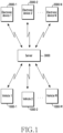
- FIG. 1 is a diagram illustrating a vehicular driving guidance system based on driving route traffic information according to various embodiments.
- the vehicular driving guidance system may include a plurality of vehicles 1000-1, 1000-2, and 1000-N, a plurality of electronic devices 2000-1, 2000-2, and 2000-N, and a server 3000.
- the plurality of the vehicles 1000-1, 1000-2, and 1000-N each may include an electronic device (e.g., an electronic device 100 of FIG. 3 , or an electronic device 100-1 of FIG. 4 ) for guiding to change a lane or a driving route based on the driving route traffic information.
- the electronic device disposed in the plurality of the vehicles 1000-1, 1000-2, and 1000-N may display information of the lane or driving route change.
- the electronic device e.g., the electronic device 100 of FIG. 3 , or the electronic device 100-1 of FIG. 4
- AR augmented reality
- HUD head-up display
- VR virtual reality
- hologram e.g., a hologram
- a flat display e.g., a liquid crystal display (LCD), an organic LED (OLED)
- the plurality of the electronic devices 2000-1, 2000-2, and 2000-N each may include a wired/wireless communication function, and transmit driving route traffic information (e.g., social data) including traffic information to the server 3000.
- driving route traffic information e.g., social data
- the social data including the traffic information may be defined as 'driving route traffic information'.
- Vehicle to vehicle (V2V) traffic information may include traffic data transmitted and received between vehicles.
- the driving route traffic information may indicate information obtained by extracting traffic related information from various social data transmitted and received between a plurality of users in addition to the V2V traffic information.
- the electronic device e.g., the electronic device 100 of FIG. 4A
- the server 3000 may extract traffic related data (e.g., Gangnam Station, Seolleung Station, road, damage, and vehicle congestion) from the message transmitted by the first user.
- the electronic device (e.g., the electronic device 100 of FIG. 4A ) and/or the server 3000 may transmit the driving route traffic information to a vehicle traveling on the same driving route.
- the plurality of the electronic devices 2000-1, 2000-2, and 2000-N each may be a communication device, a smartphone, a tablet personal computer (PC), a PC, a smart television (TV), a mobile phone, a personal digital assistant (PDA), a notebook computer, a laptop computer, a media player, a micro server, a global positioning system (GPS) device, an e-book terminal, a digital broadcasting terminal, a navigation device, and other computing device.
- the plurality of the electronic devices 2000-1, 2000-2, and 2000-N each may be a wearable device (e.g., a watch, glasses, a hair band, and a ring) including a display function and a data processing function.
- the plurality of the electronic devices 2000-1, 2000-2, and 2000-N each may be a traffic signal device (e.g., a traffic light, a traffic control device, a traffic information display device).
- the driving route traffic information may include data that users transmit traffic information such as a vehicle driving state, driving information, road information, traffic condition, accident occurrence situation, driving delay in the form of voice, a message, or a video using the plurality of the electronic devices 2000-1, 2000-2, and 2000-N and social network services (SNS).
- the driving route traffic information may include vehicle information, route information, lane information, and driving information from the plurality of the vehicles 1000-1, 1000-2, and 1000-N.
- the driving route traffic information may include data from a traffic signal device (e.g., a traffic light, a traffic control device, a traffic information display device). That is, the driving route traffic information may indicate broad traffic information related to the driving of the vehicle.
- the plurality of the vehicles 1000-1, 1000-2, and 1000-N may transmit and receive the driving information including the traffic condition using vehicle to pedestrian (V2P), V2V, and vehicle to everything (V2X) based on a 4th (4G) communication system or a 5th (5G) communication system.
- V2P vehicle to pedestrian
- V2V vehicle to everything
- 5G 5th
- the plurality of the electronic devices 2000-1, 2000-2, and 2000-N may transmit the driving route traffic information including the traffic condition to the server 3000 using V2P, V2X, and vehicle to infra (V2I) communications.
- V2P vehicle to infra
- the plurality of the electronic devices 2000-1, 2000-2, and 2000-N may receive the driving route traffic information including the traffic conditions of the plurality of the vehicles 1000-1, 1000-2, and 1000-N using V2P, V2X, and V2I communications.
- the plurality of the vehicles 1000-1, 1000-2, and 1000-N each may transmit its driving route traffic information including the traffic condition to the server 3000 using V2X and V2I communications.
- the plurality of the vehicles 1000-1, 1000-2, and 1000-N may receive the driving route traffic information including the traffic condition, driving information of other vehicles, and road condition information from the server 3000 using V2X and V2I communications.
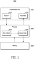
- FIG. 2 is a diagram illustrating a server 3000 shown in FIG. 1 .
- the server 3000 may include a communication unit 3100, a processor 3200, and a memory 3300.
- the communication unit 3100 may include a receiver 3110 for receiving a radio signal and a transmitter 3120 for outputting a radio signal.
- the server 3000 may transmit/receive driving route traffic information to/from the plurality of the vehicles 1000-1, 1000-2, and 1000-N and the plurality of the electronic devices 2000-1, 2000-2, and 2000-N through the communication unit 3100.
- the processor 3200 may include a data analyzer 3210 and a data arranger 3220.
- the data analyzer 3210 may analyze whether data received from the plurality of the vehicles 1000-1, 1000-2, and 1000-N and the plurality of the electronic devices 2000-1, 2000-2, and 2000-N includes traffic information.
- the data analyzer 3210 may classify each traffic information in the driving route traffic information, and provide the classification result of the driving route traffic information to the data arranger 3220.
- the data arranger 3220 may sort the received classification results of the driving route traffic information based on a preset criterion. As an embodiment, the data arranger 3220 may sort the driving route traffic information based on driving information (e.g., a location, a speed, a starting point, a target point, a driving direction, a driving route, a driving lane, etc.) of each vehicle. In addition, the data arranger 3220 may sort the driving route traffic information based on the road, and road conditions (e.g., soil runoff, oil spill, flooding, icing, pot hole, road kill, falling object, road construction, and tunnel collapse, etc.). Also, the data arranger 3220 may sort the driving route traffic information based on the traffic signal device (e.g., a traffic light, a traffic control device, a traffic information display device).
- driving information e.g., a location, a speed, a starting point, a target point, a driving direction, a driving route, a driving lane, etc.
- the data arranger 3220 may transmit the sorted driving route traffic information to the plurality of the vehicles 1000-1, 1000-2, and 1000-N through the transmitter 3120. As an embodiment, the data arranger 3220 may transmit every driving route traffic information the transmitter 3120 to the plurality of the vehicles 1000-1, 1000-2, and 1000-N in common. As an embodiment, the data arranger 3220 may distinguish vehicles of the same or similar driving routes among the plurality of the vehicles 1000-1, 1000-2, and 1000-N. Specific driving route traffic information among the entire driving route traffic information may be transmitted to the vehicles having the same or similar driving route. That is, the driving vehicle may receive the driving route traffic information corresponding to its traveling road, lane, and driving route from the server 3000.
- the memory 3300 may store the data (e.g., driving route traffic information) received from the plurality of the vehicles 1000-1, 1000-2, and 1000-N and the plurality of the electronic devices 2000-1, 2000-2, and 2000-N.
- the memory 3300 may store various data used by the processor 3200 of the server 3000.
- the data may include, for example, software (e.g., a program), and input data or output data of instructions related thereto.
- the memory 3300 may include a volatile memory and a non-volatile memory.
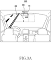
- FIG. 3A is a diagram illustrating an embodiment in which an electronic device 100 is applied to a vehicle 1000 according to various embodiments.
- the vehicle 1000 may include the electronic device 100 for displaying traffic guidance information 300 (e.g., line change information, lane change information, traffic sign and/or traffic event information) based on driving route traffic information.
- the electronic device 100 may display the traffic guidance information 300 (e.g., line change information, lane change information, traffic sign and/or traffic event information) on a window 200 of the vehicle 1000 in the AR HUD manner.
- the HUD manner may display the traffic guidance information 300 by projecting an image onto the front window 200 of the vehicle 1000. By displaying the information on the front window 200 of the vehicle 1000, the driver may recognize the traffic guidance information 300 while keeping his/her eyes on the road. It is not limited thereto, and the electronic device 100 may display the traffic guidance information 300 (e.g., line change information, lane change information, traffic sign and/or traffic event information) in a mirror display manner.
- the traffic guidance information 300 e.g., line change information, lane change information, traffic sign and/or traffic event information
- the electronic device 100 may display the traffic guidance information 300 (e.g., line change information, lane change information, traffic sign and/or traffic event information) on the window 200 of the vehicle 1000 in at least one of the two dimension three dimension AR HUD manner, the VR manner and the hologram manner.
- the electronic device 100 may display the traffic guidance information 300 (e.g., line change information, lane change information, traffic sign and/or traffic event information) in the flat display manner.
- the electronic device 100 may be a mobile or non-mobile electronic device which may be mounted on the vehicle 1000.
- the electronic device 100 may include an image sensor for acquiring a situation outside the vehicle as an image, and a GPS for acquiring location information of the vehicle 1000.
- the electronic device 100 may be operatively connected with a navigation device, a driving control device, an autonomous driving system and an advanced driver assistance system (ADAS) of the vehicle 1000, and thus share driving state, driving lane, driving route, starting point, target point information of the vehicle 1000, and/or a traffic event occurrence point.
- ADAS advanced driver assistance system
- FIG. 3B is a diagram illustrating an embodiment in which an electronic device 100-1 according to various embodiments is applied to the vehicle 1000.
- the vehicle 1000 may include the electronic device 100-1 for displaying the traffic guidance information 300 (e.g., line change information, lane change information, traffic sign and/or traffic event information) based on the driving route traffic information.
- the electronic device 100-1 may display the traffic guidance information 300 (e.g., line change information, lane change information, traffic sign and/or traffic event information) in the flat panel display (e.g., LCD, OLED) manner.
- the electronic device 100 of FIG. 3A or the electronic device 100-1 of FIG. 4A may recognize lanes on the road while driving and thus recognize the number of the lanes on the road.
- the electronic device 100 and 100-1 may recognize a currently traveling lane among the plurality of the lanes.
- the electronic device 100 and 100-1 may display the traffic guidance information 300 (e.g., line change information, lane change information, traffic sign and/or traffic event information) on a flat display 200-1 based on the traveling lane.
- the traffic guidance information 300 e.g., line change information, lane change information, traffic sign and/or traffic event information
- the electronic device 100 and 100-1 may include a sensor module 195, to increase accuracy of the line and lane determination.
- the sensor module 195 may include an image sensor, a radar sensor, and a LIDAR sensor.
- the electronic device 100 and 100-1 may recognize the line and the lane by using sensing information from the image sensor, the radar sensor, and the LIDAR sensor. It is not limited thereto, and it may be assumed that information related to the number of lanes and the lines for each road on which the vehicle 1000 is traveling is already included in map data of the navigation, or may be included in a separate database.
- the electronic device 100 may use the information related to the number of the lanes and the lines for each driving road included in the map data of the navigation, or the separate database.
- the electronic device 100 and 100-1 may display the traffic guidance information 300 (e.g., line change information, lane change information, traffic sign and/or traffic event information) in the two dimension AR HUD manner, the three dimension AR HUD manner, the VR manner, the hologram manner, or the flat display manner.
- the AR is a technology which displays a three-dimensional virtual object overlaid on the real world viewed by the driver with his/her eyes, and may be called mixed reality (MR), which shows one image by merging the virtual object having additional information and the real world in real time.
- MR mixed reality
- the electronic device 100 and 100-1 may determine it as traffic event (e.g., an accident between vehicles, vehicle breakdown, road control, ambulance driving, fire truck driving, exit warning, entry warning, and road conditions (soil runoff, oil spill, flooding, icing, pot hole, road kill, falling object, road construction, and tunnel collapse) occurrence, and display the traffic event information on the flat panel display 200-1.
- traffic event e.g., an accident between vehicles, vehicle breakdown, road control, ambulance driving, fire truck driving, exit warning, entry warning, and road conditions (soil runoff, oil spill, flooding, icing, pot hole, road kill, falling object, road construction, and tunnel collapse) occurrence, and display the traffic event information on the flat panel display 200-1.
- the traffic guidance information 300 displayed through the electronic device 100 and 100-1 may include not only the traffic event information, but also a driving speed of the vehicle 1000, a speed limit of the traveling road, and road control information according to weather conditions.
- the electronic device 100 and 100-1 is illustrated as the separate device from the vehicle 1000 in FIG. 3A and FIG. 3B , but it is not limited thereto.
- the electronic device the electronic device 100 and 100-1 may be integrated into the vehicle 1000 and implemented as some configuration included in the vehicle 1000.
- the electronic device 100 and 100-1 may include a processor (e.g., a processor 105 of FIG. 4A ) included in the vehicle 1000.
- the processor e.g., the processor 105 of FIG. 4A
- the vehicle 1000 may include a memory (e.g., a memory 185 of FIG. 4A ) for storing data required for the processor to operate and the driving route traffic information.
- the vehicle 1000 may include a communication module (e.g., a communication module 110 of FIG. 4A ) for communicating with external electronic devices, and other vehicles.
- FIG. 4A is a diagram illustrating an electronic device 100 according to various embodiments.
- the electronic device 100 may include a processor 105, a communication module 110, a display device 160, a sound output device 170, a battery 180, a memory 185, a power module 190, and a sensor module 195.
- the processor 105 may include a traffic information collector 120, a traffic information classifier 130, an event occurrence determiner 140, and a controller 150.
- FIG. 4B is a diagram illustrating the communication module 110 of the electronic device 100 shown in FIG. 4A .
- the communication module 110 may include a wireless communication module 112 (e.g., a cellular communication module, a short-range wireless communication module, or a global navigation satellite system (GNSS) communication module), a wired communication module 114, an antenna module 116, and a connection terminal 118.
- a wireless communication module 112 e.g., a cellular communication module, a short-range wireless communication module, or a global navigation satellite system (GNSS) communication module
- GNSS global navigation satellite system
- the communication module 110 may establish a direct (e.g., wired) communication channel or a wireless communication channel between the electronic device 100 and an external electronic device, another vehicle, and a server (e.g., the server 3000 of FIG. 1 ), and support communication over the established communication channel.
- the communication module 110 may include one or more communication processors which support the direct (e.g., wired) communication or the wireless communication.
- the communication module 110 may communicate with the external other electronic device, other vehicles, and the server (the server 3000 of FIG. 1 ) over a first network (e.g., a long distance communication network such as a cellular network, Internet, or a computer network (e.g., local area network (LAN) or wide area network (WAN)), or a second network (e.g., a short distance communication network such as Bluetooth, wireless fidelity (WiFi) direct or infrared data association (IrDA)).
- the wireless communication modules 112, and the wired communication modules 114 of various types may be integrated into one component (e.g., a single chip), or may be implemented as a plurality of separate components (e.g., a plurality of chips).
- the wireless communication module 112 may identify and authenticate the electronic device 100 within the communication network such as the first network or the second network using communication subscriber information (e.g., international mobile subscriber identifier (IMSI)).
- communication subscriber information e.g., international mobile subscriber identifier (IMSI)
- the antenna module 116 may transmit or receive a signal or power to outside (e.g., an external electronic device) from outside.
- the antenna module may include one antenna including a conductor formed on a substrate (e.g., a printed circuit board PCB)) or a radiator formed in a conductive pattern.
- the antenna module 116 may include a plurality of antennas. In this case, at least one antenna adequate for the communication manner used in the communication network such as the first network or the second network may be selected from the plurality of the antennas by, for example, the communication module 110.
- the signal or the power may be transmitted or received between the communication module 110 and the external electronic device, other vehicles, and the server (the server 3000 of FIG. 1 ) via the at least one selected antenna.
- RFIC radio frequency integrated circuit
- At least some of the components may be connected to each other in a communication manner between peripheral devices (e.g., a bus, general purpose input and output (GPIO), serial peripheral interface (SPI), or mobile industry processor interface (MIPI)) and exchange signals (e.g., commands or data).
- peripheral devices e.g., a bus, general purpose input and output (GPIO), serial peripheral interface (SPI), or mobile industry processor interface (MIPI)
- exchange signals e.g., commands or data
- a command or data may be transmitted or received between the electronic device 100 and the external electronic device, and other vehicles via the server (the server 3000 of FIG. 1 ) connected to the first network or the second network.
- connection terminal 118 may include a connector for electrically connecting the electronic device 100 to the external electronic device.
- the connection terminal 118 may include, for example, a high definition multimedia interface (HDMI) connector, a universal serial bus (USB) connector, a secure digital (SD) card connector, or an audio connector (e.g., a headphone connector).
- HDMI high definition multimedia interface
- USB universal serial bus
- SD secure digital
- audio connector e.g., a headphone connector
- the traffic information collector 120 of the processor 105 may receive the driving route traffic information from the server (e.g., the server 3000 of FIG. 1 ) through the communication module 110 in real time. It is not limited thereto, and the traffic information collector 120 may receive data from external electronic devices (e.g., the plurality of the electronic devices 2000-1, 2000-2, and 2000-N of FIG. 1 ), and other vehicles (e.g., the plurality of the vehicles 1000-1, 1000-2, and 1000-M of FIG. 1 ). The traffic information collector 120 may provide the driving route traffic information received in real time and the data to the traffic information classifier 130. The traffic information collector 120 may store the received driving route traffic information in the memory 185.
- the server e.g., the server 3000 of FIG. 1
- the traffic information collector 120 may receive data from external electronic devices (e.g., the plurality of the electronic devices 2000-1, 2000-2, and 2000-N of FIG. 1 ), and other vehicles (e.g., the plurality of the vehicles 1000-1, 1000-2, and
- the traffic information classifier 130 of the processor 105 may analyze the driving route traffic information received in real time, and classify specific driving route traffic information corresponding to the driving route, and the driving lane of the vehicle 1000.
- the traffic information classifying unit 130 may provide the specific driving route traffic information corresponding to the driving route, and the driving lane of the vehicle 1000 to the event occurrence determiner 140.
- the event occurrence determiner 140 of the processor 105 may analyze the received driving route traffic information and thus determine whether it is necessary to the driving route of the vehicle 1000, or to change the driving lane of the vehicle 1000. That is, the event generation determiner 140 may determine whether a traffic event has occurred to change the driving route of the vehicle 1000, or to change the driving lane of the vehicle 1000.
- the traffic event may include an accident between vehicles, vehicle breakdown, road control, ambulance driving, fire truck driving, exit warning, entry warning and road conditions (soil runoff, oil spill, flooding, icing, pot hole, road kill, falling object, road construction, and tunnel collapse.
- the event occurrence determiner 140 may generate traffic event information, if the traffic event occurs, and provide the generated traffic event information to the controller 150.
- the controller 160 of the processor 105 may include an event section detector 152, a lane change information generator 154, a traffic sign generator 156, and a severity determiner 158.
- the event section detector 152 may recognize a point where the traffic event occurs by analyzing the received traffic event information, and calculate a distance from a current location of the vehicle 1000 to the point where the traffic event occurs. In addition, the event section detector 152 may analyze the received traffic event information and thus determine a traffic event type (e.g., an accident between vehicles, vehicle breakdown, road control, ambulance driving, fire truck driving, exit warning, entry warning, and road conditions (soil runoff, oil spill, flooding, icing, pot hole, road kill, falling object, road construction, and tunnel collapse).
- a traffic event type e.g., an accident between vehicles, vehicle breakdown, road control, ambulance driving, fire truck driving, exit warning, entry warning, and road conditions (soil runoff, oil spill, flooding, icing, pot hole, road kill, falling object, road construction, and tunnel collapse).
- the event section detector 152 may generate event section information including information of how many meters (M) ahead (e.g., 500M ahead) (e.g., recognizing a distance difference between a driver's own vehicle (e.g., a vehicle connected with the electronic device) and the traffic event occurrence point) the traffic event requiring the molding route change or the lane change of the vehicle 1000 occurs based on the traffic event point and the distance to the traffic event occurrence point, and the traffic event type.
- the event section detector 152 may provide the generated event section information to the severity determiner 158. Also, the event section detector 152 may provide the event section information to the lane change information generator 154 and the traffic sign generator 156.
- the severity determiner 158 may determine severity of the generated event based on the received event section information.
- the severity determiner 158 may determine a severity level of the traffic event in consideration of a driving time increase due to the traffic event occurrence. Specifically, if an expected arrival time to the destination increases in driving along the previously guided driving route due to the traffic event occurrence, the severity determiner 158 may determine the severity level of the traffic event according to the increase of the expected arrival time. Also, the severity determination unit 158 may determine the severity level of the traffic event by considering an accident risk based on the traffic event occurrence. Specifically, if the accident risk is expected in driving along the previously guided driving route, the severity determiner 158 may determine the severity level of the traffic event in consideration of the accident risk.
- the severity determiner 158 may classify to severity low (e.g., severity of a first level) (e.g., a severity first level) having low severity of the occurred traffic event. Specifically, if the expected arrival time to the destination increases below a first increment (e.g., 20%) in driving along the previously guided driving route due to the occurrence of the traffic event, the severity determiner 158 may classify to the severity low (e.g., the severity first level). It is not limited thereto, and the severity determiner 158 may classify to the severity low (e.g., the severity first level), if the expected arrival time to the destination increases below a second increment (e.g., 30-50%).
- severity low e.g., severity of a first level
- a severity first level e.g., a severity first level
- the severity determiner 158 may classify to the severity low (e.g., the severity first level), if the severity determiner 158 does not expect the accident risk in driving along the previously guided driving route due to the traffic event occurrence.
- the severity determiner 158 may classify to the severity low (e.g., the severity first level) if it is necessary to change the current driving route or the current driving lane, but a traffic event allowing the driving occurs.
- the severity low e.g., the severity first level
- the severity determiner 158 may classify to the severity high (e.g., the severity second level) of the high severity level of the occurred event. Specifically, the severity determiner 158 may classify to the severity high (e.g., the severity second level), if the expected arrival time to the destination increases over the first increment (e.g., 20%) in driving along the previously guided driving route due to the traffic event occurrence. It is not limited thereto, and the severity determiner 158 may classify to the severity low (e.g., the severity first level), if the expected arrival time to the destination increases over the second increment (e.g., below 30-50%).
- the severity high e.g., the severity second level
- the severity low e.g., the severity first level
- the severity determiner 158 may classify to the severity high (e.g., the severity second level), if the severity determiner 158 expects the accident risk in driving along the previously guided driving route due to the traffic event occurrence.
- the severity determiner 158 may classify to the severity high (e.g., the severity second level), if a traffic event not allowing the driving on the current driving route or the current driving lane occurs.
- the severity determiner 158 may classify the severity of the event, and generate severity information.
- the severity determiner 158 may provide the severity information to the lane change information generator 154, and the traffic sign generator 156.
- the lane change information generator 154 may generate traffic guidance information 300 (e.g., traffic guidance information 300 shown in FIG. 3A , FIG. 3B ) for guiding the route change or the lane change based on the received event section information and severity information.
- the lane change information generator 154 may transmit the generated traffic guidance information 300 (e.g., the traffic guidance information 300 shown in FIG. 3A , FIG. 3B ) to the display device 160.
- the traffic sign generator 156 may generate a traffic sign (e.g., a traffic sign 400 of FIG. 5 ) including information of the occurred event, and traffic condition information based on the received event section information and severity information.
- the traffic sign generator 156 may transmit the generated traffic sign (e.g., the traffic sign 400 of FIG. 5 ) to the display device 160.
- the processor 105 may control to display at least one of the line change information, the lane change information and the traffic sign corresponding to the severity level on the display device.
- FIG. 4C is a diagram illustrating the display device 160 of the electronic device 100 shown in FIG. 4A .
- the display device 160 may include a display unit 10 for outputting an image, and a display driver IC (DDI) 30 for controlling it.
- a display driver IC DAI
- the display device 160 may display the received traffic guidance information 300 (e.g., the traffic guidance information 300 shown in FIG. 3A FIG. 3B ), and the traffic sign (e.g., the traffic sign 400 of FIG. 5 ) through the display unit 10.
- the received traffic guidance information 300 e.g., the traffic guidance information 300 shown in FIG. 3A FIG. 3B
- the traffic sign e.g., the traffic sign 400 of FIG. 5
- the display unit 10 may display the traffic guidance information 300 (e.g., the traffic guidance information 300 shown in FIG. 3A , FIG. 3B ), and the traffic sign (e.g., the traffic sign 400 of FIG. 5 ), by outputting image beams in the two dimension AR HUD manner, the three dimension AR HUD manner, the VR manner, or the hologram manner.
- the display unit 10 may display the traffic guidance information 300 (e.g., the traffic guidance information 300 shown in FIG. 3A , FIG. 3B ), and the traffic sign (e.g., the traffic sign 400 of FIG. 5 ) in the flat display (e.g., LCD, OLED) manner.
- the DDI 30 may include an interface module 31, a memory 33 (e.g., a buffer memory), an image processing module 35, or a mapping module 37.
- the DDI 30 may receive, for example, image information including image data, or an image control signal corresponding to a command for controlling the image data from other component of the electronic device 100 through the interface module 31.
- the image information may be received from the processor.
- the DDI 30 may communicate with a touch circuit 50 or a sensor module 76 through the interface module 31. Also, the DDI 30 may store at least part of the received image information in the memory 33, for example, on a frame basis.
- the image processing module 35 may preprocess or postprocess (e.g., adjust resolution, brightness, or size), for example, at least part of the image data based at least on characteristics of the image data or characteristics of the display unit 10.
- the mapping module 37 may generate a voltage value or a current value corresponding to the image data preprocessed or postprocessed by the image processing module 35.
- generation the voltage value or the current value may be performed based on, for example, properties of pixels of the image displayed through the display unit 10.
- the pixels of the image may be driven based on at least a part of the voltage value or the current value, to thus display visual information (e.g., a text, an image, or an icon) corresponding to the image data through the display unit 10.
- the display device 160 may further include the touch circuit 50.
- the touch circuit 50 may include a touch sensor 51 and a touch sensor IC 53 for controlling it.
- the touch sensor IC 53 may, for example, control the touch sensor 51 to detect a touch input or a hovering input to a specific position of the display unit 10.
- at least a part (e.g., the touch sensor IC 53) of the touch circuit 50 may be included as a part of the display driver IC 30, or the display unit, or a part of other component disposed outside the display device 160.
- the display device 160 may further include at least one sensor (e.g., a fingerprint sensor, an iris sensor, a pressure sensor or an illuminance sensor) of the sensor module 76, or a control circuit therefor.
- the at least one sensor or its control circuit may be embedded in a part of the display device 160 (e.g., the display unit 10 or the DDI 30) or a part of the touch circuit 50.
- the sound output device 170 may output a sound signal to the outside of the electronic device 100.
- the sound output device 170 may output information of a new recommended route 320 (e.g., a first lane) and a traffic sign 400 shown in FIG. 5 with a sound.
- the sound output device 170 may include, for example, a speaker or a receiver.
- the speaker may be used for general purposes such as multimedia playback or recording playback, and the receiver may be used to receive incoming calls. According to an embodiment, the receiver may be implemented separately from or as a part of the speaker.
- the battery 180 may supply power to at least one component of the electronic device 100.
- the battery 180 may include, for example, a non-rechargeable primary cell, a rechargeable secondary cell or a fuel cell.
- the power module 190 may manage the power supplied to the electronic device 100.
- the power module 190 may include a power connector for receiving alternating current (AC) power or direct current (DC) power.
- the power module 190 may be implemented as at least a part of a power management integrated circuit (PMIC).
- PMIC power management integrated circuit
- FIG. 5 is a diagram illustrating a method for displaying an existing route and a new recommended route using an electronic device according to various embodiments.
- FIG. 6A is a diagram illustrating a sign box displayed according to traffic event occurrence using an electronic device according to various embodiments.
- the electronic device 100 may display the new recommended driving route 320 (e.g., a second driving route) separately from an existing driving route 310 (e.g., a first driving route) based on traffic guidance information 300 (e.g., the traffic guidance information 300 shown in FIG. 3A , FIG. 3B ). If the vehicle 1000 traveling in the second lane which is the existing driving route 310 is subject to a driving risk due to event occurrence, or is expected to decrease the driving speed, the electronic device 100 may display the new recommended driving route 320 (e.g., the first lane).
- traffic guidance information 300 e.g., the traffic guidance information 300 shown in FIG. 3A , FIG. 3B .
- the electronic device 100 may display the existing driving route 310 (e.g., the second lane) and the new recommended driving route 320 (e.g., the first lane) in different colors.
- the electronic device 100 may display the existing driving route 310 in a first color, and display the new recommended driving route 320 (e.g., the first lane) in a second color. That is, it may control to display the existing driving route 310 and the new recommended driving route 320 in the different colors on the display device.
- the electronic device 100 may display the new recommended driving route 320 (e.g., the first lane) to overlap the existing driving route 310.
- the new recommended driving route 320 (e.g., the first lane) may include an image, and characters.
- the electronic device 100 may display the traffic sign 400 on a portion corresponding to an outer side of the road.
- the traffic sign 400 may display a distance (e.g., 300 m) from a current vehicle location to an event occurrence point and event details (e.g., accident between vehicles, vehicle breakdown, road control, ambulance driving, fire truck driving, exit warning, entry warning, and road conditions (soil runoff, oil spill, flooding, icing, pot hole, road kill, falling object, road construction, and tunnel collapse).
- event details e.g., accident between vehicles, vehicle breakdown, road control, ambulance driving, fire truck driving, exit warning, entry warning, and road conditions (soil runoff, oil spill, flooding, icing, pot hole, road kill, falling object, road construction, and tunnel collapse).
- the traffic sign 400 may include an event information display unit 410 and a severity display unit 420.
- the event information display unit 410 may display event information for displaying driving route traffic conditions.
- the severity display unit 420 may display the severity of the traffic event (e.g., the severity low (the severity first level) or the severity high (the severity second level)) in color. It is not limited thereto, and the severity display unit 420 may display the event severity using an image or a character.
- Such a traffic sign 400 may be displayed in the form of a circle sign board, a hexagonal sign box, or a polyhedral sign box.
- the traffic sign 400 may include an image, and characters.
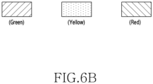
- FIG. 6B is a diagram illustrating that the color of the sign box is changed according to the severity of the traffic event occurrence.
- the severity display unit 420 of the traffic sign 400 may be displayed in a green color. If the severity of the event is low, the severity display unit 420 of the traffic sign 400 may be displayed in a yellow color. If the severity of the event is high, the severity display unit 420 of the traffic sign 400 may be displayed in a red color.
- FIG. 6C is a diagram illustrating a position where the sign box is generated.
- an event occurrence point is a specific distance (e.g., 1Km) or more away from the current location of the vehicle 1000
- event information may be displayed on an outer side of the road.
- the traffic sign 400 may be displayed by floating it over the road.
- the size of the traffic sign 400 may be gradually increased.
- the traffic sign 400 may blink at a constant speed to intuitively recognize the event occurrence.
- FIG. 7 is a diagram illustrating a method for guiding a lane change using an electronic device according to various embodiments.
- the electronic device 100 may display the new vehicle driving route 320 (e.g., the first lane), and guide to the forcible lane change. That is, it may display the impossible driving on the existing driving lane (e.g., the second lane), and information forcing to drive along the new recommended driving route 320 (e.g., the first lane) on the display device.
- the new vehicle driving route 320 e.g., the first lane
- the electronic device 100 may display the traffic sign 400 on the portion corresponding to the outer side of the road.
- the traffic sign 400 may display information of the distance to the point where the event occurs and the event. If the vehicle 1000 passes the event point, the electronic device 100 may guide the lane change to drive the vehicle 1000 along the existing lane (e.g., the second lane).
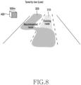
- FIG. 8 is a diagram illustrating a method for guiding a lane change, if severity of an event occurred is determined to be low (e.g., the severity first level).
- the electronic device 100 may determine the event severity as low if analyzing event information, and expecting that the vehicle 1000 which may travel along the existing driving route 310 is subject to a risk during driving, or is to decrease the speed. Specifically, the electronic device 100 may classify to the severity low (e.g., the severity first level), if the expected arrival time to the destination increases below the first increment (e.g., 20%) in driving along the previously guided existing driving route due to the traffic event occurrence.
- the severity low e.g., the severity first level
- the electronic device 100 may display the new recommended driving route 320 together with the existing driving route 310.
- the electronic device 100 may display the existing driving route 310 and the new recommended driving route 320 in different colors.
- the electronic device 100 may display the traffic sign 400 indicating the low severity on the portion corresponding to the outer side of the road.
- the traffic sign 400 may display information (a color, a character, or an image) of the low severity and event details (e.g., accident between vehicles, vehicle breakdown, road control, ambulance driving, fire truck driving, exit warning, entry warning, and road conditions (soil runoff, oil spill, flooding, icing, pot hole, road kill, falling object, road construction, and tunnel collapse).
- FIG. 9 is a diagram illustrating a method for guiding a lane change, if severity of an event occurred is determined to be high (e.g., the severity second level).
- the electronic device 100 may classify to the severity high (e.g., the severity second level) of the event occurred. Specifically, the electronic device 100 may classify to the severity high (e.g., the severity second level), if the expected arrival time to the destination increases over the first increment (e.g., 20%) in driving along the previously guided existing driving route due to the traffic event occurrence.
- the severity high e.g., the severity second level
- the electronic device 100 may determine the severity of the event as high if the vehicle 1000 may not travel on the existing driving route 310.
- the electronic device 100 may display a new essential driving route 330 together with the existing driving route 310.
- the electronic device 100 may display the existing driving route 310 and the new essential driving route 330 in different colors.
- the electronic device 100 may display the traffic sign 400 indicating the high severity on the portion corresponding to the outer side of the road.
- the traffic sign 400 may display the information (a color, a character, or an image) of the high severity and event details (e.g., accident between vehicles, vehicle breakdown, road control, ambulance driving, fire truck driving, exit warning, entry warning, and road conditions (soil runoff, oil spill, flooding, icing, pot hole, road kill, falling object, road construction, and tunnel collapse).
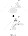
- FIG. 10 is a diagram illustrating a method for guiding a road exit based on event occurrence according to road exit unawareness and sudden lane changes of other vehicles.
- the electronic device 100 may display an exit guide 340 in advance. Also, the electronic device 100 may display the exit guide 340 if approaching a specific distance (e.g., 1Km) from the exit. Also, the electronic device 100 may display the traffic sign 400 including exit information.
- a specific distance e.g. 1Km
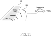
- FIG. 11 is a diagram illustrating a method for guiding a lane/route change according to lane/route deviation of a companion vehicle.
- a plurality of companion vehicles for the same destination may set the same driving route, and the companion vehicles may travel together.
- a specific vehicle among the companion vehicles may change its lane or driving route, or enter a rest area irrespective of the driving route to the destination.
- the electronic device 100 may display driving route information 360 of the companion vehicle together with the existing driving route 350.
- the electronic device 100 may display the driving route information 360 of the companion vehicle together with the existing driving route 350 on the display device if not only the companion vehicle travels ahead of the driver's own vehicle (e.g., the vehicle connected to the electronic device) but also the companion vehicle travels behind the driver's own vehicle.
- the driving route information 360 of the companion vehicle may be identically displayed in all of the companion vehicles.
- the companion vehicles may quickly and accurately recognize information that the specific vehicle of the companion vehicles deviates the driving route.
- An electronic device 100 may include a communication module 110, a processor 105 operatively coupled to the communication module 100, and a memory 185 operatively coupled to the processor 105.
- the memory 185 may, when executed, control the processor 105 to obtain driving route traffic information of a first driving route of a vehicle 1000 connected to the electronic device 100, analyze the first driving route traffic information and thus determine traffic event occurrence requiring to change a driving route or a driving lane of the vehicle 1000 connected to the electronic device 100, if the traffic event occurs, determine a severity level of the traffic event by considering a driving time increase and an accident risk, and display at least one of line change information, lane change information and a traffic sign corresponding to the severity level on a display device.
- the processor 105 of the electronic device 100 may, in driving on the first driving route, determine the severity to a first level if the driving time increases below a first increment or there is no accident risk, and in driving on the first driving route, determine the severity to a second level if the driving time increases over the first increment or an accident risk is expected.
- the processor 105 of the electronic device 100 may, acquire a current location of the vehicle 1000 connected to the electronic device 100, obtain a distance difference between the vehicle 1000 connected to the electronic device 100 and an occurrence point of the traffic event, and control to display at least one of the line change information, the lane change information and the traffic sign 400 on the display device 160 based on the distance difference.
- the processor 105 of the electronic device 100 may, control to display at least one of first line change information, first lane change information and a first traffic sign corresponding to the severity of the first level on the display device 160.
- the processor 105 of the electronic device 100 may, control to display the first driving route corresponding to the severity of the first level and a second driving route newly recommended on the display device 106.
- the processor 105 of the electronic device 100 may, control the display device 160 to display the first driving route and the second driving route differently.
- the processor 105 of the electronic device 100 may, control to display at least one of second line change information which forces to change the line, second lane change information which forces to change the lane and a second traffic sign on the display device 160 in response to the severity of the second level.
- the processor 105 of the electronic device 100 may, control to display the first driving route as an impossible driving route, and to display the second driving route newly recommended on the display device 160 in response to the severity of the second level.
- the processor 105 of the electronic device 100 may, control the display device 160 to display the first traffic sign and the second traffic sign in different colors.
- the processor 105 of the electronic device 100 may, classify types of the traffic event into accident between vehicles, vehicle breakdown, road control, ambulance driving, fire truck driving, exit warning, entry warning, soil runoff, oil spill, flooding, icing, pot hole, road kill, falling object, road construction, and tunnel collapse, and control to display the traffic sign 400 corresponding to the type of the traffic event on the display device 160.
- the processor 105 of the electronic device 100 may, display at least one of the line change information, the lane change information and the traffic sign corresponding to the severity level in at least one of a flat display manner, two dimension AR HUD manner, a three dimension AR HUD manner, a VR manner, and a hologram manner.
- the processor 105 of the electronic device 100 may, recognize driving routes of a plurality of companion vehicles for the same destination, and if a specific vehicle among the plurality of the companion vehicles having the same destination changes the driving route regardless of the destination travel route, control to display driving route changes of the specific vehicle on the display device 160.
- a vehicular driving guidance method may, collect driving route traffic information of a first driving route of a vehicle 1000 connected to an electronic device 100, analyze the first driving route traffic information and thus determining traffic event occurrence requiring to change a driving route or a driving lane of the vehicle 1000 connected to the electronic device 100, if the traffic event occurs, determine severity of the traffic event by considering a driving time increase and an accident risk, and control to display at least one of line change information, lane change information and a traffic sign corresponding to a level of the severity on a display device 160.
- the vehicular driving guidance method may, in determining the severity level, in driving on the first driving route, determine the severity to a first level if the driving time increases below a first increment or there is no accident risk, and in driving on the first driving route, determine the severity to a second level if the driving time increases over the first increment or an accident risk is expected.
- the vehicular driving guidance method may, acquire a current location of the vehicle 1000 connected to the electronic device 100, obtain a distance difference between the vehicle connected to the electronic device and an occurrence point of the traffic event, and control the display device 160 to display at least one of the line change information, the lane change information and the traffic sign based on the distance difference.
- the vehicular driving guidance method may, control to display at least one of first line change information, first lane change information and a first traffic sign corresponding to the severity of the first level on the display device 160, and control to display the first driving route corresponding to the severity of the first level and a second driving route newly recommended on the display device 160.
- the vehicular driving guidance method may, control the display device 160 to display the first driving route and the second driving route differently.
- the vehicular driving guidance method may, control to display at least one of second line change information which forces to change the line, second lane change information which forces to change the lane and a second traffic sign on the display device 160 in response to the severity of the second level, and control to display the first driving route as an impossible driving route, and to display the second driving route newly recommended on the display device 160 in response to the severity of the second level.
- the vehicular driving guidance method may, control the display device 160 to display the first traffic sign and the second traffic sign in different colors.
- the vehicular driving guidance method may, recognize driving routes of a plurality of companion vehicles for the same destination, and if a specific vehicle among the plurality of the companion vehicles having the same destination changes the driving route regardless of the destination travel route, control to display driving route changes of the specific vehicle on the display device 160.
- the electronic device may be one of various types of electronic devices.
- the electronic devices may include, for example, a portable communication device (e.g., a smartphone), a computer device, a portable multimedia device, a portable medical device, a camera, a wearable device, or a home appliance. According to an embodiment of the disclosure, the electronic devices are not limited to those described above.
- each of such phrases as “A or B,” “at least one of A and B,” “at least one of A or B,” “A, B, or C,” “at least one of A, B, and C,” and “at least one of A, B, or C,” may include any one of, or all possible combinations of the items enumerated together in a corresponding one of the phrases.
- such terms as “1st” and “2nd,” or “first” and “second” may be used to simply distinguish a corresponding component from another, and does not limit the components in other aspect (e.g., importance or order).
- an element e.g., a first element
- the element may be coupled with the other element directly (e.g., wiredly), wirelessly, or via a third element.
- module may include a unit implemented in hardware, software, or firmware, and may interchangeably be used with other terms, for example, “logic,” “logic block,” “part,” or “circuitry”.
- a module may be a single integral component, or a minimum unit or part thereof, adapted to perform one or more functions.
- the module may be implemented in a form of an application-specific integrated circuit (ASIC).
- ASIC application-specific integrated circuit
- Various embodiments as set forth herein may be implemented as software (e.g., the program) including one or more instructions that are stored in a storage medium (e.g., internal memory or external memory) that is readable by a machine (e.g., the electronic device).
- a processor e.g., the processor
- the machine e.g., the electronic device
- the one or more instructions may include a code generated by a complier or a code executable by an interpreter.
- the machine-readable storage medium may be provided in the form of a non-transitory storage medium.
- non-transitory simply means that the storage medium is a tangible device, and does not include a signal (e.g., an electromagnetic wave), but this term does not differentiate between where data is semi-permanently stored in the storage medium and where the data is temporarily stored in the storage medium.
- a method may be included and provided in a computer program product.
- the computer program product may be traded as a product between a seller and a buyer.
- the computer program product may be distributed in the form of a machine-readable storage medium (e.g., compact disc read only memory (CD-ROM)), or be distributed (e.g., downloaded or uploaded) online via an application store (e.g., PlayStore TM ), or between two user devices (e.g., smart phones) directly. If distributed online, at least part of the computer program product may be temporarily generated or at least temporarily stored in the machine-readable storage medium, such as memory of the manufacturer's server, a server of the application store, or a relay server.
- CD-ROM compact disc read only memory
- an application store e.g., PlayStore TM
- two user devices e.g., smart phones
- each component e.g., a module or a program of the above-described components may include a single entity or multiple entities, and some of the multiple entities may be separately disposed in different components. According to various embodiments, one or more of the above-described components may be omitted, or one or more other components may be added. Alternatively or additionally, a plurality of components (e.g., modules or programs) may be integrated into a single component. In such a case, according to various embodiments, the integrated component may still perform one or more functions of each of the plurality of components in the same or similar manner as they are performed by a corresponding one of the plurality of components before the integration.
- operations performed by the module, the program, or another component may be carried out sequentially, in parallel, repeatedly, or heuristically, or one or more of the operations may be executed in a different order or omitted, or one or more other operations may be added.
Landscapes
- Engineering & Computer Science (AREA)
- Radar, Positioning & Navigation (AREA)
- Remote Sensing (AREA)
- Automation & Control Theory (AREA)
- Physics & Mathematics (AREA)
- General Physics & Mathematics (AREA)
- Life Sciences & Earth Sciences (AREA)
- Atmospheric Sciences (AREA)
- Biodiversity & Conservation Biology (AREA)
- Ecology (AREA)
- Environmental & Geological Engineering (AREA)
- Environmental Sciences (AREA)
- Traffic Control Systems (AREA)
- Navigation (AREA)
Abstract
Description
- Various embodiments of the present invention relate to a vehicular driving guidance method and an electronic device based on driving route traffic information.
- A navigation technology is used to guide a driving route and to shorten a driving time. The navigation technology which guides the vehicular driving route may display the driving route from a current location to a destination according to a preset standard, and calculate and display the driving time on a display. The vehicle navigation technology may receive traffic information in real time using a communication device, search for the current location of the vehicle using a global positioning system (GPS) device, search for the destination on a map, calculate the driving route from the current location of the vehicle to the destination, and guide the driving route and the required time through a display device (including a sound device). This navigation technology may be limited to recommending the driving route and guiding an estimated driving time on a previously set map. Conventional navigation technology may not guide an accident between vehicles occurring on the road, a vehicle breakdown, a road damage, driving information of other nearby vehicles, driving route change based on traffic device information, and traffic event occurrence information.
- Various embodiments of the present invention may provide a vehicular driving guidance method and an electronic device based on driving route traffic information for guiding driving line change, driving route change and traffic event information based on unexpected traffic event (an accident between vehicles, a vehicle breakdown, road damage) information on a road and driving information of other vehicles, and traffic device information.
- An electronic device according to various embodiments of the present invention, may include a communication module, a processor operatively coupled to the communication module, and a memory operatively coupled to the processor. The memory may, when executed, control the processor to obtain driving route traffic information of a first driving route of a vehicle connected to the electronic device, analyze the first driving route traffic information and thus determine traffic event occurrence requiring to change a driving route or a driving lane of the vehicle connected to the electronic device, if the traffic event occurs, determine a severity level of the traffic event by considering a driving time increase and an accident risk, and display at least one of line change information, lane change information and a traffic sign corresponding to the severity level on a display device.
- The processor of the electronic device according to various embodiments of the present invention may, in driving on the first driving route, determine the severity to a first level if the driving time increases below a first increment or there is no accident risk, and in driving on the first driving route, determine the severity to a second level if the driving time increases over the first increment or an accident risk is expected.
- The processor of the electronic device according to various embodiments of the present invention may, acquire a current location of the vehicle connected to the electronic device, obtain a distance difference between the vehicle connected to the electronic device and an occurrence point of the traffic event, and control to display at least one of the line change information, the lane change information and the traffic sign on the display device based on the distance difference.
- The processor of the electronic device according to various embodiments of the present invention may, control to display at least one of first line change information, first lane change information and a first traffic sign corresponding to the severity of the first level on the display device.
- The processor of the electronic device according to various embodiments of the present invention may, control to display the first driving route corresponding to the severity of the first level and a second driving route newly recommended on the display device.
- The processor of the electronic device according to various embodiments of the present invention may, control the display device to display the first driving route and the second driving route differently.
- The processor of the electronic device according to various embodiments of the present invention may, control to display at least one of second line change information which forces to change the line, second lane change information which forces to change the lane and a second traffic sign on the display device in response to the severity of the second level.
- The processor of the electronic device according to various embodiments of the present invention may, control to display the first driving route as an impossible driving route, and to display the second driving route newly recommended on the display device in response to the severity of the second level.
- The processor of the electronic device according to various embodiments of the present invention may, control the display device to display the first traffic sign and the second traffic sign in different colors.
- The processor of the electronic device according to various embodiments of the present invention may, classify types of the traffic event into accident between vehicles, vehicle breakdown, road control, ambulance driving, fire truck driving, exit warning, entry warning, soil runoff, oil spill, flooding, icing, pot hole, road kill, falling object, road construction, and tunnel collapse, and control to display the traffic sign corresponding to the type of the traffic event on the display device.
- The processor of the electronic device according to various embodiments of the present invention may, display at least one of the line change information, the lane change information and the traffic sign corresponding to the severity level in at least one of a flat display manner, two dimension augmented reality (AR) head-up display (HUD) manner, a three dimension AR HUD manner, a virtual reality (VR) manner, and a hologram manner.
- The processor of the electronic device according to various embodiments of the present invention may, recognize driving routes of a plurality of companion vehicles for the same destination, and if a specific vehicle among the plurality of the companion vehicles having the same destination changes the driving route regardless of the destination travel route, control to display driving route changes of the specific vehicle on the display device.
- A vehicular driving guidance method according to various embodiments of the present invention may, collect driving route traffic information of a first driving route of a vehicle connected to an electronic device, analyze the first driving route traffic information and thus determining traffic event occurrence requiring to change a driving route or a driving lane of the vehicle connected to the electronic device, if the traffic event occurs, determine severity of the traffic event by considering a driving time increase and an accident risk, and control to display at least one of line change information, lane change information and a traffic sign corresponding to a level of the severity on a display device.
- The vehicular driving guidance method according to various embodiments of the present invention may, in determining the severity level, in driving on the first driving route, determine the severity to a first level if the driving time increases below a first increment or there is no accident risk, and in driving on the first driving route, determine the severity to a second level if the driving time increases over the first increment or an accident risk is expected.
- The vehicular driving guidance method according to various embodiments of the present invention may, acquire a current location of the vehicle connected to the electronic device, obtain a distance difference between the vehicle connected to the electronic device and an occurrence point of the traffic event, and control the display device to display at least one of the line change information, the lane change information and the traffic sign based on the distance difference.
- The vehicular driving guidance method according to various embodiments of the present invention may, control to display at least one of first line change information, first lane change information and a first traffic sign corresponding to the severity of the first level on the display device, and control to display the first driving route corresponding to the severity of the first level and a second driving route newly recommended on the display device.
- The vehicular driving guidance method according to various embodiments of the present invention may, control the display device to display the first driving route and the second driving route differently.
- The vehicular driving guidance method according to various embodiments of the present invention may, control to display at least one of second line change information which forces to change the line, second lane change information which forces to change the lane and a second traffic sign on the display device in response to the severity of the second level, and control to display the first driving route as an impossible driving route, and to display the second driving route newly recommended on the display device in response to the severity of the second level.
- The vehicular driving guidance method according to various embodiments of the present invention may, control the display device to display the first traffic sign and the second traffic sign in different colors.
- The vehicular driving guidance method according to various embodiments of the present invention may, recognize driving routes of a plurality of companion vehicles for the same destination, and if a specific vehicle among the plurality of the companion vehicles having the same destination changes the driving route regardless of the destination travel route, control to display driving route changes of the specific vehicle on the display device.
- According to various embodiments of the present invention, provided are a vehicular driving guidance method and an electronic device based on driving route traffic information for guiding driving line change, driving route change and traffic event information based on unexpected traffic event (an accident between vehicles, a vehicle breakdown, road damage) information on a road and driving information of other vehicles, and traffic device information.
- Besides, various effects directly or indirectly obtained through this document may be provided.
-
-
FIG. 1 is a diagram illustrating a vehicular driving guidance system based on driving route traffic information according to various embodiments. -
FIG. 2 is a diagram illustrating a server shown inFIG. 1 . -
FIG. 3A is a diagram illustrating an embodiment in which an electronic device is applied to a vehicle according to various embodiments. -
FIG. 3B is a diagram illustrating an embodiment in which an electronic device is applied to a vehicle according to various embodiments. -
FIG. 4A is a diagram illustrating an electronic device according to various embodiments. -
FIG. 4B is a diagram illustrating a communication module of an electronic device shown inFIG. 4A . -
FIG. 4C is a diagram illustrating a display device of an electronic device shown inFIG. 4A . -
FIG. 5 is a diagram illustrating a method for displaying an existing route and a new recommended route using an electronic device according to various embodiments. -
FIG. 6A is a diagram illustrating a sign box displayed according to traffic event occurrence using an electronic device according to various embodiments. -
FIG. 6B is a diagram illustrating that a color of a sign box is changed according to severity of traffic event occurrence. -
FIG. 6C is a diagram illustrating a position where a sign box is generated. -
FIG. 7 is a diagram illustrating a method for guiding a lane change using an electronic device according to various embodiments. -
FIG. 8 is a diagram illustrating a method for guiding a lane change, if a severity of a traffic event occurred is determined to be low. -
FIG. 9 is a diagram illustrating a method for guiding a lane change, if a severity of a traffic event occurred is determined to be high. -
FIG. 10 is a diagram illustrating a method for guiding a road exit based on traffic event occurrence according to road exit unawareness, and sudden lane changes of other vehicles. -
FIG. 11 is a diagram illustrating a method for guiding a lane/route change according to lane/route deviation of a companion vehicle. - With regard to the description of the drawings, the same or similar reference numerals may be used for the same or similar components.
- Hereinafter, various embodiments of the present invention will be described with reference to the accompanying drawings. Components shown in the drawings may be exaggerated or reduced in size for convenience of description, and the present invention is not necessarily limited to the illustrated ones.
-
FIG. 1 is a diagram illustrating a vehicular driving guidance system based on driving route traffic information according to various embodiments. - Referring to
FIG. 1 , the vehicular driving guidance system may include a plurality of vehicles 1000-1, 1000-2, and 1000-N, a plurality of electronic devices 2000-1, 2000-2, and 2000-N, and aserver 3000. The plurality of the vehicles 1000-1, 1000-2, and 1000-N each may include an electronic device (e.g., anelectronic device 100 ofFIG. 3 , or an electronic device 100-1 ofFIG. 4 ) for guiding to change a lane or a driving route based on the driving route traffic information. - The electronic device (e.g., the
electronic device 100 ofFIG. 3 or the electronic device 100-1 ofFIG. 4 ) disposed in the plurality of the vehicles 1000-1, 1000-2, and 1000-N may display information of the lane or driving route change. Herein, the electronic device (e.g., theelectronic device 100 ofFIG. 3 , or the electronic device 100-1 ofFIG. 4 ) may display the lane change information and/or the driving route change information in a two dimension augmented reality (AR) head-up display (HUD) manner, a three dimension AR HUD manner, a virtual reality (VR) manner, a hologram manner, or a flat display (e.g., a liquid crystal display (LCD), an organic LED (OLED)) manner. - The plurality of the electronic devices 2000-1, 2000-2, and 2000-N each may include a wired/wireless communication function, and transmit driving route traffic information (e.g., social data) including traffic information to the
server 3000. In this document, the social data including the traffic information may be defined as 'driving route traffic information'. - Vehicle to vehicle (V2V) traffic information may include traffic data transmitted and received between vehicles. The driving route traffic information may indicate information obtained by extracting traffic related information from various social data transmitted and received between a plurality of users in addition to the V2V traffic information. As an embodiment, if a first user transmits to a second user a message that 'I am moving from Gangnam Station to Seolleung Station, but vehicles are congested due to road damage', the electronic device (e.g., the
electronic device 100 ofFIG. 4A ) and/or theserver 3000 may extract traffic related data (e.g., Gangnam Station, Seolleung Station, road, damage, and vehicle congestion) from the message transmitted by the first user. The electronic device (e.g., theelectronic device 100 ofFIG. 4A ) and/or theserver 3000 may transmit the driving route traffic information to a vehicle traveling on the same driving route. - The plurality of the electronic devices 2000-1, 2000-2, and 2000-N each may be a communication device, a smartphone, a tablet personal computer (PC), a PC, a smart television (TV), a mobile phone, a personal digital assistant (PDA), a notebook computer, a laptop computer, a media player, a micro server, a global positioning system (GPS) device, an e-book terminal, a digital broadcasting terminal, a navigation device, and other computing device. Also, the plurality of the electronic devices 2000-1, 2000-2, and 2000-N each may be a wearable device (e.g., a watch, glasses, a hair band, and a ring) including a display function and a data processing function. In addition, the plurality of the electronic devices 2000-1, 2000-2, and 2000-N each may be a traffic signal device (e.g., a traffic light, a traffic control device, a traffic information display device).
- Herein, the driving route traffic information may include data that users transmit traffic information such as a vehicle driving state, driving information, road information, traffic condition, accident occurrence situation, driving delay in the form of voice, a message, or a video using the plurality of the electronic devices 2000-1, 2000-2, and 2000-N and social network services (SNS). Also, the driving route traffic information may include vehicle information, route information, lane information, and driving information from the plurality of the vehicles 1000-1, 1000-2, and 1000-N. In addition, the driving route traffic information may include data from a traffic signal device (e.g., a traffic light, a traffic control device, a traffic information display device). That is, the driving route traffic information may indicate broad traffic information related to the driving of the vehicle.
- The plurality of the vehicles 1000-1, 1000-2, and 1000-N may transmit and receive the driving information including the traffic condition using vehicle to pedestrian (V2P), V2V, and vehicle to everything (V2X) based on a 4th (4G) communication system or a 5th (5G) communication system.
- In addition, the plurality of the electronic devices 2000-1, 2000-2, and 2000-N may transmit the driving route traffic information including the traffic condition to the
server 3000 using V2P, V2X, and vehicle to infra (V2I) communications. - In addition, the plurality of the electronic devices 2000-1, 2000-2, and 2000-N may receive the driving route traffic information including the traffic conditions of the plurality of the vehicles 1000-1, 1000-2, and 1000-N using V2P, V2X, and V2I communications.
- In addition, the plurality of the vehicles 1000-1, 1000-2, and 1000-N each may transmit its driving route traffic information including the traffic condition to the
server 3000 using V2X and V2I communications. - In addition, the plurality of the vehicles 1000-1, 1000-2, and 1000-N may receive the driving route traffic information including the traffic condition, driving information of other vehicles, and road condition information from the
server 3000 using V2X and V2I communications. -
FIG. 2 is a diagram illustrating aserver 3000 shown inFIG. 1 . - Referring to
FIG. 2 , theserver 3000 may include acommunication unit 3100, aprocessor 3200, and amemory 3300. - The
communication unit 3100 may include areceiver 3110 for receiving a radio signal and atransmitter 3120 for outputting a radio signal. Theserver 3000 may transmit/receive driving route traffic information to/from the plurality of the vehicles 1000-1, 1000-2, and 1000-N and the plurality of the electronic devices 2000-1, 2000-2, and 2000-N through thecommunication unit 3100. - The
processor 3200 may include adata analyzer 3210 and adata arranger 3220. Thedata analyzer 3210 may analyze whether data received from the plurality of the vehicles 1000-1, 1000-2, and 1000-N and the plurality of the electronic devices 2000-1, 2000-2, and 2000-N includes traffic information. Thedata analyzer 3210 may classify each traffic information in the driving route traffic information, and provide the classification result of the driving route traffic information to thedata arranger 3220. - The
data arranger 3220 may sort the received classification results of the driving route traffic information based on a preset criterion. As an embodiment, thedata arranger 3220 may sort the driving route traffic information based on driving information (e.g., a location, a speed, a starting point, a target point, a driving direction, a driving route, a driving lane, etc.) of each vehicle. In addition, thedata arranger 3220 may sort the driving route traffic information based on the road, and road conditions (e.g., soil runoff, oil spill, flooding, icing, pot hole, road kill, falling object, road construction, and tunnel collapse, etc.). Also, thedata arranger 3220 may sort the driving route traffic information based on the traffic signal device (e.g., a traffic light, a traffic control device, a traffic information display device). - The
data arranger 3220 may transmit the sorted driving route traffic information to the plurality of the vehicles 1000-1, 1000-2, and 1000-N through thetransmitter 3120. As an embodiment, thedata arranger 3220 may transmit every driving route traffic information thetransmitter 3120 to the plurality of the vehicles 1000-1, 1000-2, and 1000-N in common. As an embodiment, thedata arranger 3220 may distinguish vehicles of the same or similar driving routes among the plurality of the vehicles 1000-1, 1000-2, and 1000-N. Specific driving route traffic information among the entire driving route traffic information may be transmitted to the vehicles having the same or similar driving route. That is, the driving vehicle may receive the driving route traffic information corresponding to its traveling road, lane, and driving route from theserver 3000. - The
memory 3300 may store the data (e.g., driving route traffic information) received from the plurality of the vehicles 1000-1, 1000-2, and 1000-N and the plurality of the electronic devices 2000-1, 2000-2, and 2000-N. Thememory 3300 may store various data used by theprocessor 3200 of theserver 3000. The data may include, for example, software (e.g., a program), and input data or output data of instructions related thereto. Thememory 3300 may include a volatile memory and a non-volatile memory. -
FIG. 3A is a diagram illustrating an embodiment in which anelectronic device 100 is applied to avehicle 1000 according to various embodiments. - Referring to
FIG. 3A , thevehicle 1000 may include theelectronic device 100 for displaying traffic guidance information 300 (e.g., line change information, lane change information, traffic sign and/or traffic event information) based on driving route traffic information. Theelectronic device 100 may display the traffic guidance information 300 (e.g., line change information, lane change information, traffic sign and/or traffic event information) on awindow 200 of thevehicle 1000 in the AR HUD manner. - The HUD manner may display the
traffic guidance information 300 by projecting an image onto thefront window 200 of thevehicle 1000. By displaying the information on thefront window 200 of thevehicle 1000, the driver may recognize thetraffic guidance information 300 while keeping his/her eyes on the road. It is not limited thereto, and theelectronic device 100 may display the traffic guidance information 300 (e.g., line change information, lane change information, traffic sign and/or traffic event information) in a mirror display manner. - As another embodiment, the
electronic device 100 may display the traffic guidance information 300 (e.g., line change information, lane change information, traffic sign and/or traffic event information) on thewindow 200 of thevehicle 1000 in at least one of the two dimension three dimension AR HUD manner, the VR manner and the hologram manner. As another example, theelectronic device 100 may display the traffic guidance information 300 (e.g., line change information, lane change information, traffic sign and/or traffic event information) in the flat display manner. - The
electronic device 100 may be a mobile or non-mobile electronic device which may be mounted on thevehicle 1000. Theelectronic device 100 may include an image sensor for acquiring a situation outside the vehicle as an image, and a GPS for acquiring location information of thevehicle 1000. Theelectronic device 100 may be operatively connected with a navigation device, a driving control device, an autonomous driving system and an advanced driver assistance system (ADAS) of thevehicle 1000, and thus share driving state, driving lane, driving route, starting point, target point information of thevehicle 1000, and/or a traffic event occurrence point. -
FIG. 3B is a diagram illustrating an embodiment in which an electronic device 100-1 according to various embodiments is applied to thevehicle 1000. - Referring to
FIG. 3B , thevehicle 1000 may include the electronic device 100-1 for displaying the traffic guidance information 300 (e.g., line change information, lane change information, traffic sign and/or traffic event information) based on the driving route traffic information. The electronic device 100-1 may display the traffic guidance information 300 (e.g., line change information, lane change information, traffic sign and/or traffic event information) in the flat panel display (e.g., LCD, OLED) manner. - The
electronic device 100 ofFIG. 3A or the electronic device 100-1 ofFIG. 4A may recognize lanes on the road while driving and thus recognize the number of the lanes on the road. Theelectronic device 100 and 100-1 may recognize a currently traveling lane among the plurality of the lanes. Theelectronic device 100 and 100-1 may display the traffic guidance information 300 (e.g., line change information, lane change information, traffic sign and/or traffic event information) on a flat display 200-1 based on the traveling lane. - The
electronic device 100 and 100-1 may include asensor module 195, to increase accuracy of the line and lane determination. Thesensor module 195 may include an image sensor, a radar sensor, and a LIDAR sensor. Theelectronic device 100 and 100-1 may recognize the line and the lane by using sensing information from the image sensor, the radar sensor, and the LIDAR sensor. It is not limited thereto, and it may be assumed that information related to the number of lanes and the lines for each road on which thevehicle 1000 is traveling is already included in map data of the navigation, or may be included in a separate database. Theelectronic device 100 may use the information related to the number of the lanes and the lines for each driving road included in the map data of the navigation, or the separate database. - The
electronic device 100 and 100-1 may display the traffic guidance information 300 (e.g., line change information, lane change information, traffic sign and/or traffic event information) in the two dimension AR HUD manner, the three dimension AR HUD manner, the VR manner, the hologram manner, or the flat display manner. As an embodiment, the AR is a technology which displays a three-dimensional virtual object overlaid on the real world viewed by the driver with his/her eyes, and may be called mixed reality (MR), which shows one image by merging the virtual object having additional information and the real world in real time. - If the
vehicle 1000 needs to change the driving lane, theelectronic device 100 and 100-1 may determine it as traffic event (e.g., an accident between vehicles, vehicle breakdown, road control, ambulance driving, fire truck driving, exit warning, entry warning, and road conditions (soil runoff, oil spill, flooding, icing, pot hole, road kill, falling object, road construction, and tunnel collapse) occurrence, and display the traffic event information on the flat panel display 200-1. - The
traffic guidance information 300 displayed through theelectronic device 100 and 100-1 may include not only the traffic event information, but also a driving speed of thevehicle 1000, a speed limit of the traveling road, and road control information according to weather conditions. - Although the
electronic device 100 and 100-1 is illustrated as the separate device from thevehicle 1000 inFIG. 3A andFIG. 3B , but it is not limited thereto. The electronic device theelectronic device 100 and 100-1 may be integrated into thevehicle 1000 and implemented as some configuration included in thevehicle 1000. For example, theelectronic device 100 and 100-1 may include a processor (e.g., aprocessor 105 ofFIG. 4A ) included in thevehicle 1000. For example, the processor (e.g., theprocessor 105 ofFIG. 4A ) may include a micro controller unit (MCU) included in thevehicle 1000. Also, thevehicle 1000 may include a memory (e.g., amemory 185 ofFIG. 4A ) for storing data required for the processor to operate and the driving route traffic information. In addition, thevehicle 1000 may include a communication module (e.g., acommunication module 110 ofFIG. 4A ) for communicating with external electronic devices, and other vehicles. -
FIG. 4A is a diagram illustrating anelectronic device 100 according to various embodiments. - Referring to
FIG. 4A , theelectronic device 100 may include aprocessor 105, acommunication module 110, adisplay device 160, asound output device 170, abattery 180, amemory 185, apower module 190, and asensor module 195. Theprocessor 105 may include atraffic information collector 120, atraffic information classifier 130, anevent occurrence determiner 140, and acontroller 150. -
FIG. 4B is a diagram illustrating thecommunication module 110 of theelectronic device 100 shown inFIG. 4A . - Referring to
FIG. 4B , thecommunication module 110 may include a wireless communication module 112 (e.g., a cellular communication module, a short-range wireless communication module, or a global navigation satellite system (GNSS) communication module), awired communication module 114, anantenna module 116, and aconnection terminal 118. - The
communication module 110 may establish a direct (e.g., wired) communication channel or a wireless communication channel between theelectronic device 100 and an external electronic device, another vehicle, and a server (e.g., theserver 3000 ofFIG. 1 ), and support communication over the established communication channel. Thecommunication module 110 may include one or more communication processors which support the direct (e.g., wired) communication or the wireless communication. - The
communication module 110 may communicate with the external other electronic device, other vehicles, and the server (theserver 3000 ofFIG. 1 ) over a first network (e.g., a long distance communication network such as a cellular network, Internet, or a computer network (e.g., local area network (LAN) or wide area network (WAN)), or a second network (e.g., a short distance communication network such as Bluetooth, wireless fidelity (WiFi) direct or infrared data association (IrDA)). Thewireless communication modules 112, and thewired communication modules 114 of various types may be integrated into one component (e.g., a single chip), or may be implemented as a plurality of separate components (e.g., a plurality of chips). - The
wireless communication module 112 may identify and authenticate theelectronic device 100 within the communication network such as the first network or the second network using communication subscriber information (e.g., international mobile subscriber identifier (IMSI)). - The
antenna module 116 may transmit or receive a signal or power to outside (e.g., an external electronic device) from outside. According to an embodiment, the antenna module may include one antenna including a conductor formed on a substrate (e.g., a printed circuit board PCB)) or a radiator formed in a conductive pattern. According to an embodiment, theantenna module 116 may include a plurality of antennas. In this case, at least one antenna adequate for the communication manner used in the communication network such as the first network or the second network may be selected from the plurality of the antennas by, for example, thecommunication module 110. The signal or the power may be transmitted or received between thecommunication module 110 and the external electronic device, other vehicles, and the server (theserver 3000 ofFIG. 1 ) via the at least one selected antenna. According to some embodiments, besides the radiator, other component (e.g., a radio frequency integrated circuit (RFIC)) may be additionally formed as a part of theantenna module 116. - At least some of the components may be connected to each other in a communication manner between peripheral devices (e.g., a bus, general purpose input and output (GPIO), serial peripheral interface (SPI), or mobile industry processor interface (MIPI)) and exchange signals (e.g., commands or data). According to an embodiment, a command or data may be transmitted or received between the
electronic device 100 and the external electronic device, and other vehicles via the server (theserver 3000 ofFIG. 1 ) connected to the first network or the second network. - The
connection terminal 118 may include a connector for electrically connecting theelectronic device 100 to the external electronic device. According to an embodiment, theconnection terminal 118 may include, for example, a high definition multimedia interface (HDMI) connector, a universal serial bus (USB) connector, a secure digital (SD) card connector, or an audio connector (e.g., a headphone connector). - Referring back to
FIG. 4A , thetraffic information collector 120 of theprocessor 105 may receive the driving route traffic information from the server (e.g., theserver 3000 ofFIG. 1 ) through thecommunication module 110 in real time. It is not limited thereto, and thetraffic information collector 120 may receive data from external electronic devices (e.g., the plurality of the electronic devices 2000-1, 2000-2, and 2000-N ofFIG. 1 ), and other vehicles (e.g., the plurality of the vehicles 1000-1, 1000-2, and 1000-M ofFIG. 1 ). Thetraffic information collector 120 may provide the driving route traffic information received in real time and the data to thetraffic information classifier 130. Thetraffic information collector 120 may store the received driving route traffic information in thememory 185. - The
traffic information classifier 130 of theprocessor 105 may analyze the driving route traffic information received in real time, and classify specific driving route traffic information corresponding to the driving route, and the driving lane of thevehicle 1000. The trafficinformation classifying unit 130 may provide the specific driving route traffic information corresponding to the driving route, and the driving lane of thevehicle 1000 to theevent occurrence determiner 140. - The
event occurrence determiner 140 of theprocessor 105 may analyze the received driving route traffic information and thus determine whether it is necessary to the driving route of thevehicle 1000, or to change the driving lane of thevehicle 1000. That is, theevent generation determiner 140 may determine whether a traffic event has occurred to change the driving route of thevehicle 1000, or to change the driving lane of thevehicle 1000. Herein, the traffic event may include an accident between vehicles, vehicle breakdown, road control, ambulance driving, fire truck driving, exit warning, entry warning and road conditions (soil runoff, oil spill, flooding, icing, pot hole, road kill, falling object, road construction, and tunnel collapse. Theevent occurrence determiner 140 may generate traffic event information, if the traffic event occurs, and provide the generated traffic event information to thecontroller 150. - The
controller 160 of theprocessor 105 may include anevent section detector 152, a lanechange information generator 154, atraffic sign generator 156, and aseverity determiner 158. - The
event section detector 152 may recognize a point where the traffic event occurs by analyzing the received traffic event information, and calculate a distance from a current location of thevehicle 1000 to the point where the traffic event occurs. In addition, theevent section detector 152 may analyze the received traffic event information and thus determine a traffic event type (e.g., an accident between vehicles, vehicle breakdown, road control, ambulance driving, fire truck driving, exit warning, entry warning, and road conditions (soil runoff, oil spill, flooding, icing, pot hole, road kill, falling object, road construction, and tunnel collapse). - The
event section detector 152 may generate event section information including information of how many meters (M) ahead (e.g., 500M ahead) (e.g., recognizing a distance difference between a driver's own vehicle (e.g., a vehicle connected with the electronic device) and the traffic event occurrence point) the traffic event requiring the molding route change or the lane change of thevehicle 1000 occurs based on the traffic event point and the distance to the traffic event occurrence point, and the traffic event type. Theevent section detector 152 may provide the generated event section information to theseverity determiner 158. Also, theevent section detector 152 may provide the event section information to the lanechange information generator 154 and thetraffic sign generator 156. - The
severity determiner 158 may determine severity of the generated event based on the received event section information. - The
severity determiner 158 may determine a severity level of the traffic event in consideration of a driving time increase due to the traffic event occurrence. Specifically, if an expected arrival time to the destination increases in driving along the previously guided driving route due to the traffic event occurrence, theseverity determiner 158 may determine the severity level of the traffic event according to the increase of the expected arrival time. Also, theseverity determination unit 158 may determine the severity level of the traffic event by considering an accident risk based on the traffic event occurrence. Specifically, if the accident risk is expected in driving along the previously guided driving route, theseverity determiner 158 may determine the severity level of the traffic event in consideration of the accident risk. - As an embodiment, the
severity determiner 158 may classify to severity low (e.g., severity of a first level) (e.g., a severity first level) having low severity of the occurred traffic event. Specifically, if the expected arrival time to the destination increases below a first increment (e.g., 20%) in driving along the previously guided driving route due to the occurrence of the traffic event, theseverity determiner 158 may classify to the severity low (e.g., the severity first level). It is not limited thereto, and theseverity determiner 158 may classify to the severity low (e.g., the severity first level), if the expected arrival time to the destination increases below a second increment (e.g., 30-50%). - As an embodiment, the
severity determiner 158 may classify to the severity low (e.g., the severity first level), if theseverity determiner 158 does not expect the accident risk in driving along the previously guided driving route due to the traffic event occurrence. - As an embodiment, the
severity determiner 158 may classify to the severity low (e.g., the severity first level) if it is necessary to change the current driving route or the current driving lane, but a traffic event allowing the driving occurs. - As an embodiment, the
severity determiner 158 may classify to the severity high (e.g., the severity second level) of the high severity level of the occurred event. Specifically, theseverity determiner 158 may classify to the severity high (e.g., the severity second level), if the expected arrival time to the destination increases over the first increment (e.g., 20%) in driving along the previously guided driving route due to the traffic event occurrence. It is not limited thereto, and theseverity determiner 158 may classify to the severity low (e.g., the severity first level), if the expected arrival time to the destination increases over the second increment (e.g., below 30-50%). - As an embodiment, the
severity determiner 158 may classify to the severity high (e.g., the severity second level), if theseverity determiner 158 expects the accident risk in driving along the previously guided driving route due to the traffic event occurrence. - As an embodiment, the
severity determiner 158 may classify to the severity high (e.g., the severity second level), if a traffic event not allowing the driving on the current driving route or the current driving lane occurs. - The
severity determiner 158 may classify the severity of the event, and generate severity information. Theseverity determiner 158 may provide the severity information to the lanechange information generator 154, and thetraffic sign generator 156. - The lane
change information generator 154 may generate traffic guidance information 300 (e.g.,traffic guidance information 300 shown inFIG. 3A ,FIG. 3B ) for guiding the route change or the lane change based on the received event section information and severity information. The lanechange information generator 154 may transmit the generated traffic guidance information 300 (e.g., thetraffic guidance information 300 shown inFIG. 3A ,FIG. 3B ) to thedisplay device 160. - The
traffic sign generator 156 may generate a traffic sign (e.g., atraffic sign 400 ofFIG. 5 ) including information of the occurred event, and traffic condition information based on the received event section information and severity information. Thetraffic sign generator 156 may transmit the generated traffic sign (e.g., thetraffic sign 400 ofFIG. 5 ) to thedisplay device 160. - As such, the
processor 105 may control to display at least one of the line change information, the lane change information and the traffic sign corresponding to the severity level on the display device. -
FIG. 4C is a diagram illustrating thedisplay device 160 of theelectronic device 100 shown inFIG. 4A . - Referring to
FIG. 4C , thedisplay device 160 may include adisplay unit 10 for outputting an image, and a display driver IC (DDI) 30 for controlling it. - The
display device 160 may display the received traffic guidance information 300 (e.g., thetraffic guidance information 300 shown inFIG. 3A FIG. 3B ), and the traffic sign (e.g., thetraffic sign 400 ofFIG. 5 ) through thedisplay unit 10. - As an embodiment, the
display unit 10 may display the traffic guidance information 300 (e.g., thetraffic guidance information 300 shown inFIG. 3A ,FIG. 3B ), and the traffic sign (e.g., thetraffic sign 400 ofFIG. 5 ), by outputting image beams in the two dimension AR HUD manner, the three dimension AR HUD manner, the VR manner, or the hologram manner. As an embodiment, thedisplay unit 10 may display the traffic guidance information 300 (e.g., thetraffic guidance information 300 shown inFIG. 3A ,FIG. 3B ), and the traffic sign (e.g., thetraffic sign 400 ofFIG. 5 ) in the flat display (e.g., LCD, OLED) manner. - The
DDI 30 may include aninterface module 31, a memory 33 (e.g., a buffer memory), animage processing module 35, or amapping module 37. TheDDI 30 may receive, for example, image information including image data, or an image control signal corresponding to a command for controlling the image data from other component of theelectronic device 100 through theinterface module 31. According to an embodiment, the image information may be received from the processor. TheDDI 30 may communicate with atouch circuit 50 or asensor module 76 through theinterface module 31. Also, theDDI 30 may store at least part of the received image information in thememory 33, for example, on a frame basis. Theimage processing module 35 may preprocess or postprocess (e.g., adjust resolution, brightness, or size), for example, at least part of the image data based at least on characteristics of the image data or characteristics of thedisplay unit 10. Themapping module 37 may generate a voltage value or a current value corresponding to the image data preprocessed or postprocessed by theimage processing module 35. - According to an embodiment, generation the voltage value or the current value may be performed based on, for example, properties of pixels of the image displayed through the
display unit 10. The pixels of the image may be driven based on at least a part of the voltage value or the current value, to thus display visual information (e.g., a text, an image, or an icon) corresponding to the image data through thedisplay unit 10. - According to an embodiment, the
display device 160 may further include thetouch circuit 50. Thetouch circuit 50 may include atouch sensor 51 and atouch sensor IC 53 for controlling it. Thetouch sensor IC 53 may, for example, control thetouch sensor 51 to detect a touch input or a hovering input to a specific position of thedisplay unit 10. According to an embodiment, at least a part (e.g., the touch sensor IC 53) of thetouch circuit 50 may be included as a part of thedisplay driver IC 30, or the display unit, or a part of other component disposed outside thedisplay device 160. - According to an embodiment, the
display device 160 may further include at least one sensor (e.g., a fingerprint sensor, an iris sensor, a pressure sensor or an illuminance sensor) of thesensor module 76, or a control circuit therefor. In this case, the at least one sensor or its control circuit may be embedded in a part of the display device 160 (e.g., thedisplay unit 10 or the DDI 30) or a part of thetouch circuit 50. - Referring back to
FIG. 4A , thesound output device 170 may output a sound signal to the outside of theelectronic device 100. Thesound output device 170 may output information of a new recommended route 320 (e.g., a first lane) and atraffic sign 400 shown inFIG. 5 with a sound. Thesound output device 170 may include, for example, a speaker or a receiver. The speaker may be used for general purposes such as multimedia playback or recording playback, and the receiver may be used to receive incoming calls. According to an embodiment, the receiver may be implemented separately from or as a part of the speaker. - The
battery 180 may supply power to at least one component of theelectronic device 100. According to an embodiment, thebattery 180 may include, for example, a non-rechargeable primary cell, a rechargeable secondary cell or a fuel cell. - The
power module 190 may manage the power supplied to theelectronic device 100. According to an embodiment, thepower module 190 may include a power connector for receiving alternating current (AC) power or direct current (DC) power. According to an embodiment, thepower module 190 may be implemented as at least a part of a power management integrated circuit (PMIC). -
FIG. 5 is a diagram illustrating a method for displaying an existing route and a new recommended route using an electronic device according to various embodiments.FIG. 6A is a diagram illustrating a sign box displayed according to traffic event occurrence using an electronic device according to various embodiments. - Referring to
FIG. 3A ,FIG. 4A ,FIG. 5 andFIG. 6A , theelectronic device 100 may display the new recommended driving route 320 (e.g., a second driving route) separately from an existing driving route 310 (e.g., a first driving route) based on traffic guidance information 300 (e.g., thetraffic guidance information 300 shown inFIG. 3A ,FIG. 3B ). If thevehicle 1000 traveling in the second lane which is the existingdriving route 310 is subject to a driving risk due to event occurrence, or is expected to decrease the driving speed, theelectronic device 100 may display the new recommended driving route 320 (e.g., the first lane). - The
electronic device 100 may display the existing driving route 310 (e.g., the second lane) and the new recommended driving route 320 (e.g., the first lane) in different colors. As an embodiment, theelectronic device 100 may display the existingdriving route 310 in a first color, and display the new recommended driving route 320 (e.g., the first lane) in a second color. That is, it may control to display the existingdriving route 310 and the new recommended drivingroute 320 in the different colors on the display device. - The
electronic device 100 may display the new recommended driving route 320 (e.g., the first lane) to overlap the existingdriving route 310. The new recommended driving route 320 (e.g., the first lane) may include an image, and characters. - The
electronic device 100 may display thetraffic sign 400 on a portion corresponding to an outer side of the road. Thetraffic sign 400 may display a distance (e.g., 300 m) from a current vehicle location to an event occurrence point and event details (e.g., accident between vehicles, vehicle breakdown, road control, ambulance driving, fire truck driving, exit warning, entry warning, and road conditions (soil runoff, oil spill, flooding, icing, pot hole, road kill, falling object, road construction, and tunnel collapse). - The
traffic sign 400 may include an eventinformation display unit 410 and aseverity display unit 420. The eventinformation display unit 410 may display event information for displaying driving route traffic conditions. Theseverity display unit 420 may display the severity of the traffic event (e.g., the severity low (the severity first level) or the severity high (the severity second level)) in color. It is not limited thereto, and theseverity display unit 420 may display the event severity using an image or a character. Such atraffic sign 400 may be displayed in the form of a circle sign board, a hexagonal sign box, or a polyhedral sign box. Thetraffic sign 400 may include an image, and characters. -
FIG. 6B is a diagram illustrating that the color of the sign box is changed according to the severity of the traffic event occurrence. - Referring to
FIG. 6B , if a traffic event does not occur and general traffic conditions are guided, theseverity display unit 420 of thetraffic sign 400 may be displayed in a green color. If the severity of the event is low, theseverity display unit 420 of thetraffic sign 400 may be displayed in a yellow color. If the severity of the event is high, theseverity display unit 420 of thetraffic sign 400 may be displayed in a red color. -
FIG. 6C is a diagram illustrating a position where the sign box is generated. - Referring to
FIG. 3A ,FIG. 4A , andFIG. 6C , if an event occurrence point is a specific distance (e.g., 1Km) or more away from the current location of thevehicle 1000, event information may be displayed on an outer side of the road. If the event occurrence point is less than the preset distance (e.g., 1Km) from the current location of thevehicle 1000, thetraffic sign 400 may be displayed by floating it over the road. As an embodiment, as thevehicle 1000 approaches the event occurrence point, the size of thetraffic sign 400 may be gradually increased. As an embodiment, thetraffic sign 400 may blink at a constant speed to intuitively recognize the event occurrence. -
FIG. 7 is a diagram illustrating a method for guiding a lane change using an electronic device according to various embodiments. - Referring to
FIG. 3A ,FIG. 4A , andFIG. 7 , if thevehicle 1000 may not travel in the existing driving lane (e.g., the second lane) due to a vehicle accident or a vehicle breakdown ahead, theelectronic device 100 may display the new vehicle driving route 320 (e.g., the first lane), and guide to the forcible lane change. That is, it may display the impossible driving on the existing driving lane (e.g., the second lane), and information forcing to drive along the new recommended driving route 320 (e.g., the first lane) on the display device. - Also, the
electronic device 100 may display thetraffic sign 400 on the portion corresponding to the outer side of the road. Thetraffic sign 400 may display information of the distance to the point where the event occurs and the event. If thevehicle 1000 passes the event point, theelectronic device 100 may guide the lane change to drive thevehicle 1000 along the existing lane (e.g., the second lane). -
FIG. 8 is a diagram illustrating a method for guiding a lane change, if severity of an event occurred is determined to be low (e.g., the severity first level). - Referring to
FIG. 3A ,FIG. 4A , andFIG. 8 , theelectronic device 100 may determine the event severity as low if analyzing event information, and expecting that thevehicle 1000 which may travel along the existingdriving route 310 is subject to a risk during driving, or is to decrease the speed. Specifically, theelectronic device 100 may classify to the severity low (e.g., the severity first level), if the expected arrival time to the destination increases below the first increment (e.g., 20%) in driving along the previously guided existing driving route due to the traffic event occurrence. - For the low severity, the
electronic device 100 may display the new recommended drivingroute 320 together with the existingdriving route 310. In this case, theelectronic device 100 may display the existingdriving route 310 and the new recommended drivingroute 320 in different colors. - The
electronic device 100 may display thetraffic sign 400 indicating the low severity on the portion corresponding to the outer side of the road. Thetraffic sign 400 may display information (a color, a character, or an image) of the low severity and event details (e.g., accident between vehicles, vehicle breakdown, road control, ambulance driving, fire truck driving, exit warning, entry warning, and road conditions (soil runoff, oil spill, flooding, icing, pot hole, road kill, falling object, road construction, and tunnel collapse). -
FIG. 9 is a diagram illustrating a method for guiding a lane change, if severity of an event occurred is determined to be high (e.g., the severity second level). - Referring to
FIG. 3A ,FIG. 4A , andFIG. 9 , by analyzing the event information, theelectronic device 100 may classify to the severity high (e.g., the severity second level) of the event occurred. Specifically, theelectronic device 100 may classify to the severity high (e.g., the severity second level), if the expected arrival time to the destination increases over the first increment (e.g., 20%) in driving along the previously guided existing driving route due to the traffic event occurrence. - By analyzing the event information, the
electronic device 100 may determine the severity of the event as high if thevehicle 1000 may not travel on the existingdriving route 310. - For the high severity, the
electronic device 100 may display a newessential driving route 330 together with the existingdriving route 310. In this case, theelectronic device 100 may display the existingdriving route 310 and the newessential driving route 330 in different colors. - The
electronic device 100 may display thetraffic sign 400 indicating the high severity on the portion corresponding to the outer side of the road. Thetraffic sign 400 may display the information (a color, a character, or an image) of the high severity and event details (e.g., accident between vehicles, vehicle breakdown, road control, ambulance driving, fire truck driving, exit warning, entry warning, and road conditions (soil runoff, oil spill, flooding, icing, pot hole, road kill, falling object, road construction, and tunnel collapse). -
FIG. 10 is a diagram illustrating a method for guiding a road exit based on event occurrence according to road exit unawareness and sudden lane changes of other vehicles. - Referring to
FIG. 3A ,FIG. 4A , andFIG. 10 , if sudden braking and sudden lane changes of other vehicles occur near the exit of the road, or other vehicles miss the exit and frequently deviate their driving route, theelectronic device 100 may display anexit guide 340 in advance. Also, theelectronic device 100 may display theexit guide 340 if approaching a specific distance (e.g., 1Km) from the exit. Also, theelectronic device 100 may display thetraffic sign 400 including exit information. -
FIG. 11 is a diagram illustrating a method for guiding a lane/route change according to lane/route deviation of a companion vehicle. - Referring to
FIG. 3A ,FIG. 4A , andFIG. 11 , a plurality of companion vehicles for the same destination may set the same driving route, and the companion vehicles may travel together. A specific vehicle among the companion vehicles may change its lane or driving route, or enter a rest area irrespective of the driving route to the destination. - If the specific vehicle among the companion vehicles changes the lane or the driving route, or enters the rest area route regardless of the driving route to the destination, the
electronic device 100 may display drivingroute information 360 of the companion vehicle together with the existingdriving route 350. Herein, theelectronic device 100 may display the drivingroute information 360 of the companion vehicle together with the existingdriving route 350 on the display device if not only the companion vehicle travels ahead of the driver's own vehicle (e.g., the vehicle connected to the electronic device) but also the companion vehicle travels behind the driver's own vehicle. The drivingroute information 360 of the companion vehicle may be identically displayed in all of the companion vehicles. Thus, the companion vehicles may quickly and accurately recognize information that the specific vehicle of the companion vehicles deviates the driving route. - An
electronic device 100 according to various embodiments of the present invention, may include acommunication module 110, aprocessor 105 operatively coupled to thecommunication module 100, and amemory 185 operatively coupled to theprocessor 105. Thememory 185 may, when executed, control theprocessor 105 to obtain driving route traffic information of a first driving route of avehicle 1000 connected to theelectronic device 100, analyze the first driving route traffic information and thus determine traffic event occurrence requiring to change a driving route or a driving lane of thevehicle 1000 connected to theelectronic device 100, if the traffic event occurs, determine a severity level of the traffic event by considering a driving time increase and an accident risk, and display at least one of line change information, lane change information and a traffic sign corresponding to the severity level on a display device. - The
processor 105 of theelectronic device 100 according to various embodiments of the present invention may, in driving on the first driving route, determine the severity to a first level if the driving time increases below a first increment or there is no accident risk, and in driving on the first driving route, determine the severity to a second level if the driving time increases over the first increment or an accident risk is expected. - The
processor 105 of theelectronic device 100 according to various embodiments of the present invention may, acquire a current location of thevehicle 1000 connected to theelectronic device 100, obtain a distance difference between thevehicle 1000 connected to theelectronic device 100 and an occurrence point of the traffic event, and control to display at least one of the line change information, the lane change information and thetraffic sign 400 on thedisplay device 160 based on the distance difference. - The
processor 105 of theelectronic device 100 according to various embodiments of the present invention may, control to display at least one of first line change information, first lane change information and a first traffic sign corresponding to the severity of the first level on thedisplay device 160. - The
processor 105 of theelectronic device 100 according to various embodiments of the present invention may, control to display the first driving route corresponding to the severity of the first level and a second driving route newly recommended on the display device 106. - The
processor 105 of theelectronic device 100 according to various embodiments of the present invention may, control thedisplay device 160 to display the first driving route and the second driving route differently. - The
processor 105 of theelectronic device 100 according to various embodiments of the present invention may, control to display at least one of second line change information which forces to change the line, second lane change information which forces to change the lane and a second traffic sign on thedisplay device 160 in response to the severity of the second level. - The
processor 105 of theelectronic device 100 according to various embodiments of the present invention may, control to display the first driving route as an impossible driving route, and to display the second driving route newly recommended on thedisplay device 160 in response to the severity of the second level. - The
processor 105 of theelectronic device 100 according to various embodiments of the present invention may, control thedisplay device 160 to display the first traffic sign and the second traffic sign in different colors. - The
processor 105 of theelectronic device 100 according to various embodiments of the present invention may, classify types of the traffic event into accident between vehicles, vehicle breakdown, road control, ambulance driving, fire truck driving, exit warning, entry warning, soil runoff, oil spill, flooding, icing, pot hole, road kill, falling object, road construction, and tunnel collapse, and control to display thetraffic sign 400 corresponding to the type of the traffic event on thedisplay device 160. - The
processor 105 of theelectronic device 100 according to various embodiments of the present invention may, display at least one of the line change information, the lane change information and the traffic sign corresponding to the severity level in at least one of a flat display manner, two dimension AR HUD manner, a three dimension AR HUD manner, a VR manner, and a hologram manner. - The
processor 105 of theelectronic device 100 according to various embodiments of the present invention may, recognize driving routes of a plurality of companion vehicles for the same destination, and if a specific vehicle among the plurality of the companion vehicles having the same destination changes the driving route regardless of the destination travel route, control to display driving route changes of the specific vehicle on thedisplay device 160. - A vehicular driving guidance method according to various embodiments of the present invention may, collect driving route traffic information of a first driving route of a
vehicle 1000 connected to anelectronic device 100, analyze the first driving route traffic information and thus determining traffic event occurrence requiring to change a driving route or a driving lane of thevehicle 1000 connected to theelectronic device 100, if the traffic event occurs, determine severity of the traffic event by considering a driving time increase and an accident risk, and control to display at least one of line change information, lane change information and a traffic sign corresponding to a level of the severity on adisplay device 160. - The vehicular driving guidance method according to various embodiments of the present invention may, in determining the severity level, in driving on the first driving route, determine the severity to a first level if the driving time increases below a first increment or there is no accident risk, and in driving on the first driving route, determine the severity to a second level if the driving time increases over the first increment or an accident risk is expected.
- The vehicular driving guidance method according to various embodiments of the present invention may, acquire a current location of the
vehicle 1000 connected to theelectronic device 100, obtain a distance difference between the vehicle connected to the electronic device and an occurrence point of the traffic event, and control thedisplay device 160 to display at least one of the line change information, the lane change information and the traffic sign based on the distance difference. - The vehicular driving guidance method according to various embodiments of the present invention may, control to display at least one of first line change information, first lane change information and a first traffic sign corresponding to the severity of the first level on the
display device 160, and control to display the first driving route corresponding to the severity of the first level and a second driving route newly recommended on thedisplay device 160. - The vehicular driving guidance method according to various embodiments of the present invention may, control the
display device 160 to display the first driving route and the second driving route differently. - The vehicular driving guidance method according to various embodiments of the present invention may, control to display at least one of second line change information which forces to change the line, second lane change information which forces to change the lane and a second traffic sign on the
display device 160 in response to the severity of the second level, and control to display the first driving route as an impossible driving route, and to display the second driving route newly recommended on thedisplay device 160 in response to the severity of the second level. - The vehicular driving guidance method according to various embodiments of the present invention may, control the
display device 160 to display the first traffic sign and the second traffic sign in different colors. - The vehicular driving guidance method according to various embodiments of the present invention may, recognize driving routes of a plurality of companion vehicles for the same destination, and if a specific vehicle among the plurality of the companion vehicles having the same destination changes the driving route regardless of the destination travel route, control to display driving route changes of the specific vehicle on the
display device 160. - The electronic device according to various embodiments may be one of various types of electronic devices. The electronic devices may include, for example, a portable communication device (e.g., a smartphone), a computer device, a portable multimedia device, a portable medical device, a camera, a wearable device, or a home appliance. According to an embodiment of the disclosure, the electronic devices are not limited to those described above.
- It should be appreciated that various embodiments of the present disclosure and the terms used therein are not intended to limit the technological features set forth herein to particular embodiments and include various changes, equivalents, or replacements for a corresponding embodiment. With regard to the description of the drawings, similar reference numerals may be used to refer to similar or related elements. It is to be understood that a singular form of a noun corresponding to an item may include one or more of the things, unless the relevant context clearly indicates otherwise. As used herein, each of such phrases as "A or B," "at least one of A and B," "at least one of A or B," "A, B, or C," "at least one of A, B, and C," and "at least one of A, B, or C," may include any one of, or all possible combinations of the items enumerated together in a corresponding one of the phrases. As used herein, such terms as "1st" and "2nd," or "first" and "second" may be used to simply distinguish a corresponding component from another, and does not limit the components in other aspect (e.g., importance or order). It is to be understood that if an element (e.g., a first element) is referred to, with or without the term "operatively" or "communicatively", as "coupled with," "coupled to," "connected with," or "connected to" another element (e.g., a second element), it means that the element may be coupled with the other element directly (e.g., wiredly), wirelessly, or via a third element.
- As used in connection with various embodiments of the disclosure, the term "module" may include a unit implemented in hardware, software, or firmware, and may interchangeably be used with other terms, for example, "logic," "logic block," "part," or "circuitry". A module may be a single integral component, or a minimum unit or part thereof, adapted to perform one or more functions. For example, according to an embodiment, the module may be implemented in a form of an application-specific integrated circuit (ASIC).
- Various embodiments as set forth herein may be implemented as software (e.g., the program) including one or more instructions that are stored in a storage medium (e.g., internal memory or external memory) that is readable by a machine (e.g., the electronic device). For example, a processor (e.g., the processor) of the machine (e.g., the electronic device) may invoke at least one of the one or more instructions stored in the storage medium, and execute it, with or without using one or more other components under the control of the processor. This allows the machine to be operated to perform at least one function according to the at least one instruction invoked. The one or more instructions may include a code generated by a complier or a code executable by an interpreter. The machine-readable storage medium may be provided in the form of a non-transitory storage medium. Wherein, the term "non-transitory" simply means that the storage medium is a tangible device, and does not include a signal (e.g., an electromagnetic wave), but this term does not differentiate between where data is semi-permanently stored in the storage medium and where the data is temporarily stored in the storage medium.
- According to an embodiment, a method according to various embodiments of the disclosure may be included and provided in a computer program product. The computer program product may be traded as a product between a seller and a buyer. The computer program product may be distributed in the form of a machine-readable storage medium (e.g., compact disc read only memory (CD-ROM)), or be distributed (e.g., downloaded or uploaded) online via an application store (e.g., PlayStore™), or between two user devices (e.g., smart phones) directly. If distributed online, at least part of the computer program product may be temporarily generated or at least temporarily stored in the machine-readable storage medium, such as memory of the manufacturer's server, a server of the application store, or a relay server.
- According to various embodiments, each component (e.g., a module or a program) of the above-described components may include a single entity or multiple entities, and some of the multiple entities may be separately disposed in different components. According to various embodiments, one or more of the above-described components may be omitted, or one or more other components may be added. Alternatively or additionally, a plurality of components (e.g., modules or programs) may be integrated into a single component. In such a case, according to various embodiments, the integrated component may still perform one or more functions of each of the plurality of components in the same or similar manner as they are performed by a corresponding one of the plurality of components before the integration. According to various embodiments, operations performed by the module, the program, or another component may be carried out sequentially, in parallel, repeatedly, or heuristically, or one or more of the operations may be executed in a different order or omitted, or one or more other operations may be added.
Claims (15)
- An electronic device comprising:a communication module;a processor operatively coupled to the communication module; anda memory operatively coupled to the processor;wherein the memory, when executed, controls the processor to,obtain driving route traffic information of a first driving route of a vehicle connected to the electronic device,analyze the first driving route traffic information and thus determine traffic event occurrence requiring to change a driving route or a driving lane of the vehicle connected to the electronic device,if the traffic event occurs, determine a severity level of the traffic event by considering a driving time increase and an accident risk, anddisplay at least one of line change information, lane change information and a traffic sign corresponding to the severity level on a display device.
- The electronic device of claim 1, wherein the processor,in driving on the first driving route, determines the severity to a first level if the driving time increases below a first increment or there is no accident risk, andin driving on the first driving route, determines the severity to a second level if the driving time increases over the first increment or an accident risk is expected.
- The electronic device of claim 2, wherein the processor,acquires a current location of the vehicle connected to the electronic device,obtains a distance difference between the vehicle connected to the electronic device and an occurrence point of the traffic event, andcontrols to display at least one of the line change information, the lane change information and the traffic sign on the display device based on the distance difference.
- The electronic device of claim 2, wherein the processor,
controls to display at least one of first line change information, first lane change information and a first traffic sign corresponding to the severity of the first level on the display device. - The electronic device of claim 4, wherein the processor,
controls to display the first driving route corresponding to the severity of the first level and a second driving route newly recommended on the display device. - The electronic device of claim 5, wherein the processor,
controls the display device to display the first driving route and the second driving route differently. - The electronic device of claim 4, wherein the processor,
controls to display at least one of second line change information which forces to change the line, second lane change information which forces to change the lane and a second traffic sign on the display device in response to the severity of the second level. - The electronic device of claim 7, wherein the processor,
controls to display the first driving route as an impossible driving route, and to display the second driving route newly recommended on the display device in response to the severity of the second level. - The electronic device of claim 7, wherein the processor,
controls the display device to display the first traffic sign and the second traffic sign in different colors. - The electronic device of claim 1, wherein the processor,classifies types of the traffic event into accident between vehicles, vehicle breakdown, road control, ambulance driving, fire truck driving, exit warning, entry warning, soil runoff, oil spill, flooding, icing, pot hole, road kill, falling object, road construction, and tunnel collapse, andcontrols to display the traffic sign corresponding to the type of the traffic event on the display device.
- The electronic device of claim 1, wherein the processor,
displays at least one of the line change information, the lane change information and the traffic sign corresponding to the severity level in at least one of a flat display manner, two dimension augmented reality (AR) head-up display (HUD) manner, a three dimension AR HUD manner, a virtual reality (VR) manner, and a hologram manner. - The electronic device of claim 1, wherein the processor,recognizes driving routes of a plurality of companion vehicles for the same destination, andif a specific vehicle among the plurality of the companion vehicles having the same destination changes the driving route regardless of the destination travel route, controls to display driving route changes of the specific vehicle on the display device.
- A vehicular driving guidance method comprising:collecting driving route traffic information of a first driving route of a vehicle connected to an electronic device;analyzing the first driving route traffic information and thus determining traffic event occurrence requiring to change a driving route or a driving lane of the vehicle connected to the electronic device;if the traffic event occurs, determining severity of the traffic event by considering a driving time increase and an accident risk; andcontrolling to display at least one of line change information, lane change information and a traffic sign corresponding to a level of the severity on a display device.
- The vehicular driving guidance method of claim 1, wherein determining the severity level,in driving on the first driving route, determines the severity to a first level if the driving time increases below a first increment or there is no accident risk, andin driving on the first driving route, determines the severity to a second level if the driving time increases over the first increment or an accident risk is expected.
- The vehicular driving guidance method of claim 14, wherein a current location of the vehicle connected to the electronic device is acquired,a distance difference between the vehicle connected to the electronic device and an occurrence point of the traffic event is obtained, andthe display device is controlled to display at least one of the line change information, the lane change information and the traffic sign based on the distance difference.
Applications Claiming Priority (2)
| Application Number | Priority Date | Filing Date | Title |
|---|---|---|---|
| KR1020200039811A KR20210122535A (en) | 2020-04-01 | 2020-04-01 | Method And Electronic Device of Driving Guidance For Vechicle |
| PCT/KR2021/001947 WO2021201425A1 (en) | 2020-04-01 | 2021-02-16 | Vehicular driving guidance method and electronic device |
Publications (3)
| Publication Number | Publication Date |
|---|---|
| EP4130671A1 true EP4130671A1 (en) | 2023-02-08 |
| EP4130671A4 EP4130671A4 (en) | 2023-09-27 |
| EP4130671B1 EP4130671B1 (en) | 2025-06-11 |
Family
ID=77929079
Family Applications (1)
| Application Number | Title | Priority Date | Filing Date |
|---|---|---|---|
| EP21779896.6A Active EP4130671B1 (en) | 2020-04-01 | 2021-02-16 | Vehicular driving guidance method and electronic device |
Country Status (5)
| Country | Link |
|---|---|
| US (1) | US12320664B2 (en) |
| EP (1) | EP4130671B1 (en) |
| KR (1) | KR20210122535A (en) |
| CN (1) | CN115427761B (en) |
| WO (1) | WO2021201425A1 (en) |
Families Citing this family (4)
| Publication number | Priority date | Publication date | Assignee | Title |
|---|---|---|---|---|
| WO2024035048A1 (en) * | 2022-08-08 | 2024-02-15 | 주식회사 아이나비시스템즈 | Route guidance service apparatus |
| CN116222599B (en) * | 2023-02-08 | 2026-03-20 | 阿里巴巴(中国)有限公司 | Navigation prompts methods, devices, equipment, and procedures during cruise mode |
| CN117565817B (en) * | 2023-12-18 | 2025-10-10 | 芜湖汽车前瞻技术研究院有限公司 | Intelligent vehicle control method, device, electronic device and storage medium |
| US20250239155A1 (en) * | 2024-01-24 | 2025-07-24 | GM Global Technology Operations LLC | Method and system for efficient passage of emergency vehicles through a roadway |
Family Cites Families (18)
| Publication number | Priority date | Publication date | Assignee | Title |
|---|---|---|---|---|
| JP2004132897A (en) * | 2002-10-11 | 2004-04-30 | Mitsubishi Electric Corp | Car navigation system |
| US20070010941A1 (en) * | 2005-07-07 | 2007-01-11 | Marsh David C | Land navigation system |
| KR100975828B1 (en) | 2008-08-11 | 2010-08-13 | 서강대학교산학협력단 | Navigation service method and system and terminal according thereto |
| KR100957137B1 (en) * | 2009-02-26 | 2010-05-11 | 한국과학기술원 | System and method for controlling group driving |
| GB201218681D0 (en) * | 2012-10-17 | 2012-11-28 | Tomtom Int Bv | Methods and systems of providing information using a navigation apparatus |
| GB2524512A (en) * | 2014-03-25 | 2015-09-30 | Jaguar Land Rover Ltd | Navigation system and method |
| JP6642972B2 (en) * | 2015-03-26 | 2020-02-12 | 修一 田山 | Vehicle image display system and method |
| KR102188637B1 (en) | 2015-04-01 | 2020-12-08 | 한국전자통신연구원 | Lane change information system |
| KR101750876B1 (en) * | 2015-05-28 | 2017-06-26 | 엘지전자 주식회사 | Display apparatus for vehicle and Vehicle |
| US10453337B2 (en) * | 2015-06-25 | 2019-10-22 | Here Global B.V. | Method and apparatus for providing safety levels estimate for a travel link based on signage information |
| KR101750159B1 (en) * | 2015-07-01 | 2017-06-22 | 엘지전자 주식회사 | Assistance Apparatus for Driving of a Vehicle, Method thereof, and Vehicle having the same |
| US10503168B1 (en) * | 2016-01-22 | 2019-12-10 | State Farm Mutual Automotive Insurance Company | Autonomous vehicle retrieval |
| KR102471072B1 (en) * | 2016-12-21 | 2022-11-25 | 삼성전자주식회사 | Electronic apparatus and operating method for the same |
| KR20180112949A (en) | 2017-04-05 | 2018-10-15 | 현대자동차주식회사 | Autonomous Travelling Control Ststem And Control Metheod Using It |
| US10451436B2 (en) * | 2017-04-12 | 2019-10-22 | Microsoft Technology Licensing, Llc | Generating routes using events |
| JP6922425B2 (en) | 2017-05-29 | 2021-08-18 | 株式会社デンソー | Vehicle display control device and display control program |
| US11597403B2 (en) * | 2018-04-11 | 2023-03-07 | Hyundai Motor Company | Apparatus for displaying driving state of vehicle, system including the same and method thereof |
| KR102727108B1 (en) | 2018-09-14 | 2024-11-06 | 현대자동차주식회사 | Traffic guidance system and method |
-
2020
- 2020-04-01 KR KR1020200039811A patent/KR20210122535A/en active Pending
-
2021
- 2021-02-16 CN CN202180026589.0A patent/CN115427761B/en active Active
- 2021-02-16 WO PCT/KR2021/001947 patent/WO2021201425A1/en not_active Ceased
- 2021-02-16 EP EP21779896.6A patent/EP4130671B1/en active Active
-
2022
- 2022-09-30 US US17/958,128 patent/US12320664B2/en active Active
Also Published As
| Publication number | Publication date |
|---|---|
| WO2021201425A1 (en) | 2021-10-07 |
| KR20210122535A (en) | 2021-10-12 |
| US12320664B2 (en) | 2025-06-03 |
| EP4130671A4 (en) | 2023-09-27 |
| CN115427761A (en) | 2022-12-02 |
| US20230024275A1 (en) | 2023-01-26 |
| CN115427761B (en) | 2025-07-29 |
| EP4130671B1 (en) | 2025-06-11 |
Similar Documents
| Publication | Publication Date | Title |
|---|---|---|
| US12320664B2 (en) | Vehicular driving guidance method and electronic device | |
| CN111284487B (en) | Lane line display method and electronic device for executing same | |
| US12272155B2 (en) | Method for detecting vehicle and device for executing the same | |
| US11049327B2 (en) | Electronic apparatus, control method thereof, computer program, and computer-readable recording medium | |
| EP3282228B1 (en) | Dynamic-map constructing method, dynamic-map constructing system and moving terminal | |
| US10147001B2 (en) | Electronic apparatus and control method thereof | |
| US20110098916A1 (en) | Navigation method of mobile terminal and apparatus thereof | |
| KR102233391B1 (en) | Electronic apparatus, control method of electronic apparatus and computer readable recording medium | |
| CN110567475A (en) | Navigation method, navigation device, computer readable storage medium and electronic equipment | |
| KR20130053137A (en) | Mobile terminal and menthod for controlling of the same | |
| JP2024052900A (en) | Communication device and communication method | |
| KR20210056632A (en) | Method for image processing based on message and electronic device implementing the same | |
| KR20160028140A (en) | System for providing signal waiting time for vehicle and control method thereof | |
| EP3896968A1 (en) | Image processing device, image processing method, and image processing system | |
| KR20200070101A (en) | Method for displaying lane information and apparatus for executing the method | |
| KR102611775B1 (en) | Method and electronic device for transmitting group message | |
| KR102406490B1 (en) | Electronic apparatus, control method of electronic apparatus, computer program and computer readable recording medium | |
| KR20200070100A (en) | A method for detecting vehicle and device for executing the method | |
| KR102299500B1 (en) | Electronic apparatus and control method thereof | |
| KR20150033428A (en) | Electronic device and control method for the electronic device | |
| KR20230030706A (en) | Vehicle and control method for the same | |
| US20250265925A1 (en) | Roadside device | |
| KR102058620B1 (en) | Electronic device and driving related guidance maethod for moving body | |
| KR20210038495A (en) | Electronic apparatus, control method of electronic apparatus and computer readable recording medium | |
| KR20210005818A (en) | Electronic apparatus and control method thereof |
Legal Events
| Date | Code | Title | Description |
|---|---|---|---|
| STAA | Information on the status of an ep patent application or granted ep patent |
Free format text: STATUS: THE INTERNATIONAL PUBLICATION HAS BEEN MADE |
|
| PUAI | Public reference made under article 153(3) epc to a published international application that has entered the european phase |
Free format text: ORIGINAL CODE: 0009012 |
|
| STAA | Information on the status of an ep patent application or granted ep patent |
Free format text: STATUS: REQUEST FOR EXAMINATION WAS MADE |
|
| 17P | Request for examination filed |
Effective date: 20221026 |
|
| AK | Designated contracting states |
Kind code of ref document: A1 Designated state(s): AL AT BE BG CH CY CZ DE DK EE ES FI FR GB GR HR HU IE IS IT LI LT LU LV MC MK MT NL NO PL PT RO RS SE SI SK SM TR |
|
| DAV | Request for validation of the european patent (deleted) | ||
| DAX | Request for extension of the european patent (deleted) | ||
| A4 | Supplementary search report drawn up and despatched |
Effective date: 20230829 |
|
| RIC1 | Information provided on ipc code assigned before grant |
Ipc: G01C 21/36 20060101ALI20230823BHEP Ipc: G01C 21/34 20060101AFI20230823BHEP |
|
| GRAP | Despatch of communication of intention to grant a patent |
Free format text: ORIGINAL CODE: EPIDOSNIGR1 |
|
| STAA | Information on the status of an ep patent application or granted ep patent |
Free format text: STATUS: GRANT OF PATENT IS INTENDED |
|
| GRAS | Grant fee paid |
Free format text: ORIGINAL CODE: EPIDOSNIGR3 |
|
| INTG | Intention to grant announced |
Effective date: 20250408 |
|
| GRAA | (expected) grant |
Free format text: ORIGINAL CODE: 0009210 |
|
| STAA | Information on the status of an ep patent application or granted ep patent |
Free format text: STATUS: THE PATENT HAS BEEN GRANTED |
|
| AK | Designated contracting states |
Kind code of ref document: B1 Designated state(s): AL AT BE BG CH CY CZ DE DK EE ES FI FR GB GR HR HU IE IS IT LI LT LU LV MC MK MT NL NO PL PT RO RS SE SI SK SM TR |
|
| REG | Reference to a national code |
Ref country code: GB Ref legal event code: FG4D Free format text: NOT ENGLISH |
|
| REG | Reference to a national code |
Ref country code: CH Ref legal event code: EP |
|
| REG | Reference to a national code |
Ref country code: IE Ref legal event code: FG4D |
|
| REG | Reference to a national code |
Ref country code: DE Ref legal event code: R096 Ref document number: 602021032185 Country of ref document: DE |
|
| PG25 | Lapsed in a contracting state [announced via postgrant information from national office to epo] |
Ref country code: FI Free format text: LAPSE BECAUSE OF FAILURE TO SUBMIT A TRANSLATION OF THE DESCRIPTION OR TO PAY THE FEE WITHIN THE PRESCRIBED TIME-LIMIT Effective date: 20250611 Ref country code: ES Free format text: LAPSE BECAUSE OF FAILURE TO SUBMIT A TRANSLATION OF THE DESCRIPTION OR TO PAY THE FEE WITHIN THE PRESCRIBED TIME-LIMIT Effective date: 20250611 |
|
| REG | Reference to a national code |
Ref country code: LT Ref legal event code: MG9D |
|
| PG25 | Lapsed in a contracting state [announced via postgrant information from national office to epo] |
Ref country code: NO Free format text: LAPSE BECAUSE OF FAILURE TO SUBMIT A TRANSLATION OF THE DESCRIPTION OR TO PAY THE FEE WITHIN THE PRESCRIBED TIME-LIMIT Effective date: 20250911 Ref country code: GR Free format text: LAPSE BECAUSE OF FAILURE TO SUBMIT A TRANSLATION OF THE DESCRIPTION OR TO PAY THE FEE WITHIN THE PRESCRIBED TIME-LIMIT Effective date: 20250912 |
|
| REG | Reference to a national code |
Ref country code: NL Ref legal event code: MP Effective date: 20250611 |
|
| PG25 | Lapsed in a contracting state [announced via postgrant information from national office to epo] |
Ref country code: BG Free format text: LAPSE BECAUSE OF FAILURE TO SUBMIT A TRANSLATION OF THE DESCRIPTION OR TO PAY THE FEE WITHIN THE PRESCRIBED TIME-LIMIT Effective date: 20250611 |
|
| PG25 | Lapsed in a contracting state [announced via postgrant information from national office to epo] |
Ref country code: HR Free format text: LAPSE BECAUSE OF FAILURE TO SUBMIT A TRANSLATION OF THE DESCRIPTION OR TO PAY THE FEE WITHIN THE PRESCRIBED TIME-LIMIT Effective date: 20250611 |
|
| PG25 | Lapsed in a contracting state [announced via postgrant information from national office to epo] |
Ref country code: RS Free format text: LAPSE BECAUSE OF FAILURE TO SUBMIT A TRANSLATION OF THE DESCRIPTION OR TO PAY THE FEE WITHIN THE PRESCRIBED TIME-LIMIT Effective date: 20250911 |
|
| PG25 | Lapsed in a contracting state [announced via postgrant information from national office to epo] |
Ref country code: LV Free format text: LAPSE BECAUSE OF FAILURE TO SUBMIT A TRANSLATION OF THE DESCRIPTION OR TO PAY THE FEE WITHIN THE PRESCRIBED TIME-LIMIT Effective date: 20250611 |
|
| PG25 | Lapsed in a contracting state [announced via postgrant information from national office to epo] |
Ref country code: NL Free format text: LAPSE BECAUSE OF FAILURE TO SUBMIT A TRANSLATION OF THE DESCRIPTION OR TO PAY THE FEE WITHIN THE PRESCRIBED TIME-LIMIT Effective date: 20250611 |
|
| PG25 | Lapsed in a contracting state [announced via postgrant information from national office to epo] |
Ref country code: PT Free format text: LAPSE BECAUSE OF FAILURE TO SUBMIT A TRANSLATION OF THE DESCRIPTION OR TO PAY THE FEE WITHIN THE PRESCRIBED TIME-LIMIT Effective date: 20251013 |
|
| REG | Reference to a national code |
Ref country code: AT Ref legal event code: MK05 Ref document number: 1802583 Country of ref document: AT Kind code of ref document: T Effective date: 20250611 |
|
| PG25 | Lapsed in a contracting state [announced via postgrant information from national office to epo] |
Ref country code: IS Free format text: LAPSE BECAUSE OF FAILURE TO SUBMIT A TRANSLATION OF THE DESCRIPTION OR TO PAY THE FEE WITHIN THE PRESCRIBED TIME-LIMIT Effective date: 20251011 |
|
| PG25 | Lapsed in a contracting state [announced via postgrant information from national office to epo] |
Ref country code: AT Free format text: LAPSE BECAUSE OF FAILURE TO SUBMIT A TRANSLATION OF THE DESCRIPTION OR TO PAY THE FEE WITHIN THE PRESCRIBED TIME-LIMIT Effective date: 20250611 Ref country code: SM Free format text: LAPSE BECAUSE OF FAILURE TO SUBMIT A TRANSLATION OF THE DESCRIPTION OR TO PAY THE FEE WITHIN THE PRESCRIBED TIME-LIMIT Effective date: 20250611 |
|
| PG25 | Lapsed in a contracting state [announced via postgrant information from national office to epo] |
Ref country code: CZ Free format text: LAPSE BECAUSE OF FAILURE TO SUBMIT A TRANSLATION OF THE DESCRIPTION OR TO PAY THE FEE WITHIN THE PRESCRIBED TIME-LIMIT Effective date: 20250611 |
|
| PG25 | Lapsed in a contracting state [announced via postgrant information from national office to epo] |
Ref country code: PL Free format text: LAPSE BECAUSE OF FAILURE TO SUBMIT A TRANSLATION OF THE DESCRIPTION OR TO PAY THE FEE WITHIN THE PRESCRIBED TIME-LIMIT Effective date: 20250611 |
|
| PG25 | Lapsed in a contracting state [announced via postgrant information from national office to epo] |
Ref country code: EE Free format text: LAPSE BECAUSE OF FAILURE TO SUBMIT A TRANSLATION OF THE DESCRIPTION OR TO PAY THE FEE WITHIN THE PRESCRIBED TIME-LIMIT Effective date: 20250611 |
|
| PG25 | Lapsed in a contracting state [announced via postgrant information from national office to epo] |
Ref country code: SK Free format text: LAPSE BECAUSE OF FAILURE TO SUBMIT A TRANSLATION OF THE DESCRIPTION OR TO PAY THE FEE WITHIN THE PRESCRIBED TIME-LIMIT Effective date: 20250611 |
|
| REG | Reference to a national code |
Ref country code: DE Ref legal event code: R097 Ref document number: 602021032185 Country of ref document: DE |
|
| PG25 | Lapsed in a contracting state [announced via postgrant information from national office to epo] |
Ref country code: DK Free format text: LAPSE BECAUSE OF FAILURE TO SUBMIT A TRANSLATION OF THE DESCRIPTION OR TO PAY THE FEE WITHIN THE PRESCRIBED TIME-LIMIT Effective date: 20250611 |
|
| PGFP | Annual fee paid to national office [announced via postgrant information from national office to epo] |
Ref country code: DE Payment date: 20260120 Year of fee payment: 6 |
|
| PG25 | Lapsed in a contracting state [announced via postgrant information from national office to epo] |
Ref country code: IT Free format text: LAPSE BECAUSE OF FAILURE TO SUBMIT A TRANSLATION OF THE DESCRIPTION OR TO PAY THE FEE WITHIN THE PRESCRIBED TIME-LIMIT Effective date: 20250611 |
|
| PLBE | No opposition filed within time limit |
Free format text: ORIGINAL CODE: 0009261 |
|
| STAA | Information on the status of an ep patent application or granted ep patent |
Free format text: STATUS: NO OPPOSITION FILED WITHIN TIME LIMIT |
|
| REG | Reference to a national code |
Ref country code: CH Ref legal event code: L10 Free format text: ST27 STATUS EVENT CODE: U-0-0-L10-L00 (AS PROVIDED BY THE NATIONAL OFFICE) Effective date: 20260423 |