EP4130627A1 - Heat exchange system, and fin structure of heat exchanger - Google Patents
Heat exchange system, and fin structure of heat exchanger Download PDFInfo
- Publication number
- EP4130627A1 EP4130627A1 EP21781079.5A EP21781079A EP4130627A1 EP 4130627 A1 EP4130627 A1 EP 4130627A1 EP 21781079 A EP21781079 A EP 21781079A EP 4130627 A1 EP4130627 A1 EP 4130627A1
- Authority
- EP
- European Patent Office
- Prior art keywords
- heat exchange
- flow path
- fin portions
- mode
- heat exchanger
- Prior art date
- Legal status (The legal status is an assumption and is not a legal conclusion. Google has not performed a legal analysis and makes no representation as to the accuracy of the status listed.)
- Granted
Links
Images






Classifications
-
- F—MECHANICAL ENGINEERING; LIGHTING; HEATING; WEAPONS; BLASTING
- F28—HEAT EXCHANGE IN GENERAL
- F28D—HEAT-EXCHANGE APPARATUS, NOT PROVIDED FOR IN ANOTHER SUBCLASS, IN WHICH THE HEAT-EXCHANGE MEDIA DO NOT COME INTO DIRECT CONTACT
- F28D9/00—Heat-exchange apparatus having stationary plate-like or laminated conduit assemblies for both heat-exchange media, the media being in contact with different sides of a conduit wall
- F28D9/0062—Heat-exchange apparatus having stationary plate-like or laminated conduit assemblies for both heat-exchange media, the media being in contact with different sides of a conduit wall the conduits for one heat-exchange medium being formed by spaced plates with inserted elements
-
- F—MECHANICAL ENGINEERING; LIGHTING; HEATING; WEAPONS; BLASTING
- F28—HEAT EXCHANGE IN GENERAL
- F28D—HEAT-EXCHANGE APPARATUS, NOT PROVIDED FOR IN ANOTHER SUBCLASS, IN WHICH THE HEAT-EXCHANGE MEDIA DO NOT COME INTO DIRECT CONTACT
- F28D1/00—Heat-exchange apparatus having stationary conduit assemblies for one heat-exchange medium only, the media being in contact with different sides of the conduit wall, in which the other heat-exchange medium is a large body of fluid, e.g. domestic or motor car radiators
- F28D1/02—Heat-exchange apparatus having stationary conduit assemblies for one heat-exchange medium only, the media being in contact with different sides of the conduit wall, in which the other heat-exchange medium is a large body of fluid, e.g. domestic or motor car radiators with heat-exchange conduits immersed in the body of fluid
- F28D1/0233—Heat-exchange apparatus having stationary conduit assemblies for one heat-exchange medium only, the media being in contact with different sides of the conduit wall, in which the other heat-exchange medium is a large body of fluid, e.g. domestic or motor car radiators with heat-exchange conduits immersed in the body of fluid with air flow channels
- F28D1/024—Heat-exchange apparatus having stationary conduit assemblies for one heat-exchange medium only, the media being in contact with different sides of the conduit wall, in which the other heat-exchange medium is a large body of fluid, e.g. domestic or motor car radiators with heat-exchange conduits immersed in the body of fluid with air flow channels with an air driving element
-
- F—MECHANICAL ENGINEERING; LIGHTING; HEATING; WEAPONS; BLASTING
- F28—HEAT EXCHANGE IN GENERAL
- F28F—DETAILS OF HEAT-EXCHANGE AND HEAT-TRANSFER APPARATUS, OF GENERAL APPLICATION
- F28F27/00—Control arrangements or safety devices specially adapted for heat-exchange or heat-transfer apparatus
-
- F—MECHANICAL ENGINEERING; LIGHTING; HEATING; WEAPONS; BLASTING
- F28—HEAT EXCHANGE IN GENERAL
- F28F—DETAILS OF HEAT-EXCHANGE AND HEAT-TRANSFER APPARATUS, OF GENERAL APPLICATION
- F28F3/00—Plate-like or laminated elements; Assemblies of plate-like or laminated elements
- F28F3/02—Elements or assemblies thereof with means for increasing heat-transfer area, e.g. with fins, with recesses, with corrugations
- F28F3/025—Elements or assemblies thereof with means for increasing heat-transfer area, e.g. with fins, with recesses, with corrugations the means being corrugated, plate-like elements
-
- F—MECHANICAL ENGINEERING; LIGHTING; HEATING; WEAPONS; BLASTING
- F28—HEAT EXCHANGE IN GENERAL
- F28F—DETAILS OF HEAT-EXCHANGE AND HEAT-TRANSFER APPARATUS, OF GENERAL APPLICATION
- F28F2215/00—Fins
- F28F2215/10—Secondary fins, e.g. projections or recesses on main fins
-
- F—MECHANICAL ENGINEERING; LIGHTING; HEATING; WEAPONS; BLASTING
- F28—HEAT EXCHANGE IN GENERAL
- F28F—DETAILS OF HEAT-EXCHANGE AND HEAT-TRANSFER APPARATUS, OF GENERAL APPLICATION
- F28F2250/00—Arrangements for modifying the flow of the heat exchange media, e.g. flow guiding means; Particular flow patterns
- F28F2250/08—Fluid driving means, e.g. pumps, fans
Definitions
- the present invention relates to a heat exchange system and a fin structure of a heat exchanger, and in particular, to a heat exchange system and a fin structure of a heat exchanger that perform heat exchange by natural convection and heat exchange by forcing air to flow in.
- a heat exchange system and a fin structure of a heat exchanger that perform heat exchange by natural convection and heat exchange by forcing air to flow in are known.
- Such a heat exchange system is disclosed in, for example, JP-S61-197416U .
- JP-S61-197416U discloses a heat exchanger including a plurality of conduits, a connecting pipe having a U shape that connects the conduits, a plurality of fins, and a motor fan.
- the plurality of conduits are disposed in parallel and have end portions connected by the connecting pipe having a U shape.
- the plurality of fins are disposed to form a forced convection part with a narrowed pitch (disposition interval) and natural convection parts.
- the forced convection part is provided in a central portion of the plurality of fins, and the natural convection parts are provided on right and left sides of the forced convection part.
- the motor fan is provided in the forced convection part.
- the heat exchanger disclosed in JP-S61-197416U is configured to switch between natural convection and forced convection as needed to perform cooling (heat exchange).
- the forced convection part disclosed in JP-S61-197416U since the forced convection part disclosed in JP-S61-197416U has the disposition interval of the fins narrower (smaller) than in the natural convection parts, the forced convection part increases in flow path resistance. In such a configuration, though not clearly stated in JP-S61-197416U , the forced convection part cannot be used in heat exchange by natural convection. For this reason, in the configuration disclosed in JP-S61-197416U , heat exchange by natural convection is performed only in the natural convection parts, and heat exchange by forcing air to flow in is performed only in the forced convection part.
- the plurality of fins are divided into fins used only in heat exchange by natural convection and fins used only in heat exchange by forcing air to flow in. That is, since a part of the plurality of fins is used only in heat exchange by natural convection, and the remaining fins are used only in heat exchange by forcing air to flow in, the number of fins used in heat exchange by natural convection and the number of fins used in heat exchange by forcing air to flow in decrease compared to a configuration in which heat exchange is performed using all fins. For this reason, in a case of switching between performing heat exchange by natural convection and heat exchange by forcing air to flow in, there is a problem in that heat exchange efficiency of respective heat exchange is degraded.
- the invention has been accomplished to solve the problem described above, and an object of the invention is to provide a heat exchange system and a fin structure of a heat exchanger capable of, in a case of switching between performing heat exchange by natural convection and heat exchange by forcing air to flow in, suppressing degradation of heat exchange efficiency of respective heat exchange.
- the present inventors have conducted intensive studies and have found that a plurality of fin portions in a first flow path of a heat exchanger undulate to be usable in both heat exchange by natural convection and heat exchange by forcing air to flow into the first flow path.
- a heat exchange system includes a heat exchanger including a base portion that comes into contact with a heat exchange target, and a first flow path which is divided by a plurality of fin portions extending upward from the base portion and through which air flows, a fan that makes air flow into the first flow path, and a control unit that performs control for switching between a first mode where heat exchange of the heat exchange target is performed by forcing air to flow into the first flow path with the fan and a second mode where the heat exchange of the heat exchange target is performed by natural convection, in which the plurality of fin portions are disposed in parallel at predetermined intervals in a width direction of the first flow path, the plurality of fin portions are formed to have an undulating shape from one end toward the other end of the first flow path in the width direction of the first flow path, and the first flow path is configured to be used in both the first mode and the second mode.
- the plurality of fin portions are disposed in parallel at the predetermined intervals in the width direction of the first flow path through which air flows, and are formed to have the undulating shape from one end toward the other end of the first flow path in the width direction of the first flow path, and the first flow path is configured to be used in both the first mode where the heat exchange is performed by forcing air to flow in and the second mode where the heat exchange is performed by the natural convection.
- the first flow path is used in both the first mode and the second mode, it is possible to suppress a decrease in the number of fin portions used in each heat exchange mode, compared to a configuration in which fin portions including both fin portions used only in the first mode and fin portions used only in the second mode are provided in the first flow path.
- the plurality of fin portions have the undulating shape in the width direction of the first flow path, it is possible to promote heat transfer with turbulence of flown-in air, compared to a configuration in which the plurality of fin portions do not have an undulating shape. It is possible to increase a heat transfer area without narrowing the disposition interval of the fin portions. As a result, in a case of switching between performing heat exchange by natural convection and heat exchange by forcing air to flow in, it is possible to suppress degradation of heat exchange efficiency of respective heat exchange.
- the plurality of fin portions are provided continuously from the one end to the other end of the first flow path and undulate periodically such that the other end of the first flow path is visible as viewed from the one end of the first flow path.
- a through flow path is formed in the first flow path. Accordingly, it is possible to suppress an increase in pressure loss of air flowing in the first flow path, compared to a configuration in which a through flow path is not formed in the first flow path with the plurality of fin portions.
- the plurality of fin portions have the undulating shape, it is possible to secure heat exchange efficiency in the second mode where heat exchange is performed by natural convection.
- the plurality of fin portions are provided continuously from the one end to the other end of the first flow path and undulate periodically such that the other end of the first flow path is visible as viewed from the one end of the first flow path, preferably, the plurality of fin portions undulate such that an undulating pattern of the same waveform is repeated at a fixed undulation width in the width direction of the first flow path, and the undulation width is at least a size less than a half of a disposition interval of the plurality of fin portions.
- the plurality of fin portions undulate such that the undulating pattern of the same waveform is repeated at the fixed undulation width in the width direction of the first flow path, it is possible to simplify the structure (shape) of the plurality of fin portions, compared to a configuration in which the undulation width and/or the undulating pattern of the plurality of fin portions is different halfway. Since the undulation width of the plurality of fin portions is at least the size less than a half of the disposition interval of the plurality of fin portions, it is possible to make a configuration in which the other end of the first flow path is visible as viewed from the one end of the first flow path, and to secure heat exchange efficiency in the second mode. As a result, it is possible to achieve both the simplification of the structure (shape) of the plurality of fin portions and securing of heat exchange efficiency in the second mode.
- the plurality of fin portions undulate such that an undulating pattern of the same waveform is repeated at a fixed undulation width in the width direction of the first flow path, the undulating pattern includes a crest portion that protrudes to one side, a trough portion that protrudes to the other side, and a connecting portion that connects the crest portion and the trough portion, in the width direction of the first flow path, and a maximum inclination angle of the connecting portion with respect to a direction from one end side to the other end side of the first flow path is within an angle range of equal to or greater than 10 degrees and equal to or less than 30 degrees.
- a disposition interval of the plurality of fin portions is within a range of equal to or greater than 5 mm and equal to or less than 10 mm.
- the plurality of fin portions are disposed at equal intervals over a whole width in the width direction of the first flow path.
- the control unit is configured to switch between the first mode and the second mode based on a temperature of the heat exchange target.
- the heat exchange target includes a heat exchange target fluid
- the heat exchanger further includes a second flow path through which the heat exchange target fluid flows in a state of being in contact with the base portion where a plurality of fin portions are provided.
- a fin structure of a heat exchanger includes a base portion that comes into contact with a heat exchange target, and a plurality of fin portions provided to extend upward from the base portion, in which the plurality of fin portions form a first flow path through which air flows, have an undulating shape from one end toward the other end of the formed first flow path in a width direction of the first flow path, are disposed at equal intervals over a whole width in the width direction of the first flow path, are provided continuously from the one end to the other end of the first flow path, and, undulate periodically such that the other end of the first flow path is visible as viewed from the one end of the first flow path, and in performing heat exchange of the heat exchange target, the first flow path is configured to be used in both forced heat exchange where the heat exchange of the heat exchange target is performed by forcing air to flow into the first flow path and natural heat exchange where the heat exchange of the heat exchange target is performed by natural convection.
- the plurality of fin portions are disposed in parallel at the predetermined intervals in the width direction of the first flow path, and have the undulating shape from one end toward the other end of the first flow path in the width direction of the first flow path.
- the plurality of fin portions are disposed at the equal intervals over the whole width in the width direction of the first flow path, it is possible to perform heat exchange by the first mode and heat exchange by the second mode using the whole first flow path, unlike a configuration in which a part where heat exchange is performed by the first mode and a part where heat exchange is performed by the second mode are formed by changing the disposition interval of the plurality of fin portions halfway of the first flow path. As a result, it is possible to suppress degradation of heat exchange efficiency of each heat exchange mode.
- the plurality of fin portions are provided continuously from one end to the other end of the first flow path, and undulate periodically such that the other end of the first flow path is visible as viewed from one end of the first flow path.
- a through flow path is formed in the first flow path. Accordingly, it is possible to suppress an increase in pressure loss of air flowing in the first flow path, compared to a configuration in which a through flow path is not formed in the first flow path with the plurality of fin portions.
- the plurality of fin portions have the undulating shape, it is possible to secure heat exchange efficiency in the second mode where heat exchange is performed by natural convection.
- a heat exchange system 100 includes a heat exchanger 1, a fan 2, a control unit 3, a first temperature sensor 4, and a second temperature sensor 5.
- an up-down direction is represented as a Z direction
- an up direction is represented as a Z1 direction
- a down direction is represented as a Z2 direction.
- Two directions perpendicular to each other within a plane perpendicular to the Z direction are represented as an X direction and a Y direction.
- the X direction one side is represented as an X1 direction
- the other side is represented as an X2 direction.
- the Y direction one side is represented as a Y1 direction
- the other side is represented as a Y2 direction.
- the heat exchanger 1 has an opening that is an inlet or an outlet of a fluid and is configured to make the fluid flow to perform heat exchange.
- Fig. 1 shows an example where the heat exchanger 1 is a plate fin type heat exchanger.
- the plate fin type heat exchanger 1 has a rectangular parallelepiped shape including a surface (side surface) where the opening is formed.
- the heat exchanger 1 has a flow path for making the fluid flow inside and is configured to perform heat exchange in a process of making the fluid flow.
- the heat exchange that is performed by the heat exchanger 1 includes cooling and heating. In the present embodiment, a case where the heat exchanger 1 performs cooling of a heat exchange target will be described.
- the heat exchanger 1 has a structure in which separate plates 10, first corrugated fins 13, and second corrugated fins 14 are laminated.
- First side bars 15 are disposed on in outer peripheral portions of each first corrugated fin 13.
- Second side bars 16 are disposed in outer peripheral portions of each second corrugated fin 14.
- the first corrugated fins 13, the second corrugated fins 14, the separate plates 10, the first side bars 15, and the second side bars 16 are bonded by brazing, whereby the heat exchanger 1 is configured.
- Each separate plate 10 is an example of a "base portion" in the claims.
- a first flow path 11 is divided by the separate plate 10, the first side bar 15, and the separate plate 10, and is configured with each layer where the first corrugated fin 13 is disposed inside. Air as the fluid flows in the first flow path 11.
- the first flow path 11 is formed to extend in the up-down direction (Z direction).
- the Y direction is a width direction of the first flow path 11.
- the X direction is a height direction of the first flow path 11.
- a second flow path 12 is divided by the separate plate 10, the second side bar 16, and the separate plate 10, and is configured with each layer where the second corrugated fin 14 is disposed inside.
- a heat exchange target fluid flows in the second flow path 12 in a state of being in contact with the separate plate 10.
- the heat exchanger 1 performs heat exchange between air and the heat exchange target fluid flowing in the first flow path 11 and the second flow path 12, respectively.
- air flows into the first flow path 11 from a Z2 direction side and flows out from a Z1 direction side.
- the heat exchange target fluid flows into the second flow path 12 from a Y1 direction side and flows out from a Y2 direction side.
- the separate plate 10 has a rectangular shape.
- the separate plate 10 is configured to come into contact with the heat exchange target.
- the heat exchange target includes the heat exchange target fluid.
- the heat exchange target fluid includes, for example, oil or a refrigerant.
- the heat exchanger 1 has a structure in which the first flow path 11 and the second flow path 12 are alternately laminated such that the first flow path 11 and the second flow path 12 are perpendicular to each other.
- the first flow path 11 and the second flow path 12 are laminated in the X direction.
- the heat exchanger 1 includes surfaces 1a where an opening 11a of the first flow path 11 is formed and surfaces 1b where an opening 12a of the second flow path 12 is formed.
- the opening 11a of the first flow path 11 is formed in both surfaces 1a in the Z direction and the opening 12a of the second flow path 12 is formed in both surfaces 1b on a Y direction side perpendicular to the surface 1a.
- the opening 11a is formed in a portion of the surface 1a excluding the second flow path 12.
- the opening 12a is formed in a portion of the surface 1b excluding the first flow path 11.
- the fan 2 is configured to make air flow into the first flow path 11 under the control of the control unit 3.
- the fan 2 is configured to make air flow into the first flow path 11 from the opening 11a on the Z2 direction side.
- the fan 2 is provided in a state of being in contact with the surface 1a on the Z2 direction side to close the opening 11a on the Z2 direction side.
- the fan 2 includes, for example, a blower that blows air into the first flow path 11.
- the control unit 3 is configured to perform control for switching between a first mode where the heat exchange of the heat exchange target is performed by forcing air to flow into the first flow path 11 with the fan 2 and a second mode where the heat exchange of the heat exchange target is performed by natural convection.
- the control unit 3 is configured to acquire a temperature difference between air and the heat exchange target based on a temperature of air acquired by the first temperature sensor 4 and a temperature of the heat exchange target acquired by the second temperature sensor 5.
- the first flow path 11 is configured to be used in both the first mode and the second mode.
- the control unit 3 includes, for example, a central processing unit (CPU), a read only memory (ROM), and a random access memory (RAM).
- the first temperature sensor 4 is configured to acquire the temperature of air.
- the first temperature sensor 4 is provided in the vicinity of the opening 11a on the Z2 direction side and acquires the temperature of air flowing into the first flow path 11.
- the first temperature sensor 4 is configured to output the acquired temperature of air to the control unit 3.
- the second temperature sensor 5 is configured to acquire the temperature of the heat exchange target.
- the second temperature sensor 5 is provided in the vicinity of the opening 12a on the Y1 direction side and acquires the temperature of the heat exchange target flowing into the second flow path 12.
- the second temperature sensor 5 is configured to output the acquired temperature of the heat exchange target to the control unit 3.
- the first flow path 11 is formed by the separate plate 10 and one first corrugated fin 13.
- the separate plate 10 on an X1 direction side is not shown.
- the first corrugated fin 13 includes a plurality of fin portions 13a, a first connecting portion 13b, and a second connecting portion 13c.
- the plurality of fin portions 13a are provided to extend upward from the separate plate 10.
- the plurality of fin portions 13a are provided to extend upward from the separate plate 10 from an X2 direction side toward the X1 direction side.
- the plurality of fin portions 13a are connected by the first connecting portion 13b on the X1 direction side.
- the plurality of fin portions 13a are connected by the second connecting portion 13c on the X2 direction side.
- the first connecting portion 13b and the second connecting portion 13c are alternately provided in the Y direction.
- the first flow path 11 is divided by the plurality of fin portions 13a provided to extend upward from the separate plate 10.
- the plurality of fin portions 13a are disposed in parallel at predetermined intervals p1 in the width direction (Y direction) of the first flow path 11.
- the plurality of fin portions 13a are formed to have an undulating shape from one end 11b toward the other end 11c of the first flow path 11 in the width direction (Y direction) of the first flow path 11.
- the plurality of fin portions 13a are disposed at the intervals p1 and at equal intervals over the whole width in the width direction (Y direction) of the first flow path 11.
- the interval p1 of the plurality of fin portions 13a is a distance of a gap portion of the fin portions 13a excluding a plate thickness.
- the undulating shape is a shape in which a crest portion 11d and a trough portion 11e are alternately repeated in a direction (Z direction) from one end 11b toward the other end 11c of the first flow path 11.
- the plurality of fin portions 13a undulate in a period p2.
- the period p2 is a distance between the crest portions 11d on the Y1 direction side of the fin portion 13a in the Z direction.
- the plurality of fin portions 13a undulate such that an undulating pattern of the same waveform is repeated at a fixed undulation width W in the width direction (Y direction) of the first flow path 11.
- the undulation width W is a distance between the crest portion 11d on the Y1 direction side of the fin portion 13a and the trough portion 11e on the Y1 direction side of the fin portion 13a.
- the undulating pattern means a unit of repetition in the Z direction in a case where the plurality of fin portions 13a undulate.
- the distance between a trough portion 11g on the Y2 direction side of the fin portion 13a and a crest portion 11f on the Y2 direction side of the fin portion 13a is equal to the distance between the crest portion 11d on the Y1 direction side of the fin portion 13a and the trough portion 11e on the Y1 direction side of the fin portion 13a.
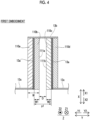
- Fig. 4 is a schematic view as the first flow path 11 is viewed from the Z1 direction side.
- Fig. 4 shows the fin portions 13a, the first connecting portion 13b, the second connecting portions 13c, a surface 110a in the crest portion 11d (see Fig. 3 ) of the fin portion 13a that is visible from the Z2 direction side, a surface 110b in the trough portion 11e (see Fig. 3 ) of the fin portion 13a that is visible from the Z2 direction side, a surface 110c in the crest portion 11f (see Fig. 3 ) of the fin portion 13a that is visible from the Z2 direction side, and a surface 110d in the trough portion 11g (see Fig.
- Fig. 4 is not a sectional view, and the separate plate 10, the fin portions 13a, the first connecting portion 13b, the second connecting portions 13c, and the surface 110a to the surface 110d are hatched differently for ease of identification.
- the plurality of fin portions 13a undulate periodically such that the other end 11c of the first flow path 11 is visible as viewed from one end 11b of the first flow path 11.
- the undulation width W is at least a size less than a half of the interval p1 of the plurality of fin portions 13a.
- the plurality of fin portions 13a undulate such that a distance D between an end portion 111a on the Y2 direction side of the surface 110b and an end portion 111b on the Y1 direction side of the surface 110c is not 0 (zero).
- the plurality of fin portions 13a undulate such that a size obtained by adding a width W1 in the Y direction of the surface 110b and a width W2 in the Y direction of the surface 110c of each of the plurality of fin portions 13a is smaller than the interval p1 of the plurality of fin portions 13a.
- the interval p1 of the plurality of fin portions 13a is within a range of equal to or greater than 5 mm and equal to or less than 10 mm.
- the interval p1 of the plurality of fin portions 13a is, for example, about 8 mm.
- a thickness of the first fin portion is about 0.25 mm.
- the first flow path 11 in performing the heat exchange of the heat exchange target, is used in both forced heat exchange where the heat exchange of the heat exchange target is performed by forcing air to flow into the first flow path 11 and natural heat exchange where the heat exchange of the heat exchange target is performed by natural convection.
- the heat exchanger 1 according to the present embodiment can be used in both forced heat exchange and natural heat exchange by performing a simulation using the heat exchanger 1 according to the present embodiment and the comparative example.
- a simulation result described below is obtained by cooling the heat exchange target using the heat exchanger 1 according to the embodiment and a comparative example.
- a graph G1 shown in Fig. 5 shows change in heat exchange amount in changing a front face wind velocity using the heat exchanger 1 in the present embodiment and a heat exchanger according to the comparative example.
- the graph G1 takes a heat exchange amount (kW: kilowatt) as the vertical axis and takes a front face wind velocity (m/s: millimeters per second) as the horizontal axis.
- the front face wind velocity is a wind velocity of air in the opening 11a in flowing into the heat exchanger 1, and is not a wind velocity of air that flows among the plurality of fin portions 13a.
- the simulation result shown in the graph G1 is a result obtained by performing a simulation in a state where a temperature of air in the opening 11a in flowing into the first flow path 11 is fixed at 30 degrees, and a temperature of the heat exchange target fluid that flows in the second flow path 12 is fixed at 85 degrees.
- a heat exchanger in which fins having a thickness of about 0.25 mm are disposed at disposition intervals of about 8 mm is used.
- a heat exchanger for natural heat exchange that includes fins disposed suitably for natural heat exchange and a heat exchanger for forced heat exchange that includes fins suitable for forced heat exchange are used.
- the heat exchanger for natural heat exchange is, for example, a heat exchanger in which fins having a thickness of about 0.25 mm are disposed at disposition intervals of about 8 mm.
- the heat exchanger for forced heat exchange is, for example, a heat exchanger in which fins having a thickness of about 0.25 mm are disposed at disposition intervals of about 3.4 mm.
- Both the fins of the heat exchanger for natural heat exchange and the fins of the heat exchanger for forced heat exchange do not have an undulating shape from one end toward the other end of the first flow path in the Y direction.
- the fins of the heat exchanger for natural heat exchange and the fins of the heat exchanger for forced heat exchange are configured with plain type corrugated fins.
- a simulation result of the heat exchanger 1 according to the present embodiment is shown by a solid line 20.
- a simulation result of the heat exchanger for natural heat exchange is shown by a broken line 21.
- a simulation result of the heat exchanger for forced heat exchange is shown by a one-dot chain line 22.
- a value of a simulation result by natural heat exchange is shown at a position where the front face wind velocity is 0 (zero).
- a result shows that the heat exchange amount of the heat exchanger for natural heat exchange is the greatest, and the heat exchange amount of the heat exchanger 1 according to the present embodiment is the second greatest, and the heat exchange amount of the heat exchanger for forced heat exchange is the smallest.
- a case where the front face wind velocity is 0 (zero) is heat exchange by natural convection. That is, a case where the front face wind velocity is 0 (zero) is heat exchange by the second mode.
- a case where the front face wind velocity is equal to or higher than 0 (zero) is heat exchange by the first mode.
- the heat exchange amount of the heat exchanger for forced heat exchange is the greatest, and the heat exchange amount of the heat exchanger for natural heat exchange is the smallest.
- the heat exchange amount of the heat exchanger for forced heat exchange is the greatest, and the heat exchange amount of the heat exchanger for natural heat exchange is the smallest.
- the heat exchange amount of the heat exchanger 1 according to the present embodiment is the greatest, and the heat exchange amount of the heat exchanger for natural heat exchange is the smallest.
- a ratio of the heat exchange amount of the heat exchanger 1 according to the present embodiment to the heat exchange amount of the heat exchanger for forced heat exchange is about 96%.
- a ratio of the heat exchange amount of the heat exchanger for natural heat exchange to the heat exchange amount of the heat exchanger for forced heat exchange is about 39%.
- a ratio of the heat exchange amount of the heat exchanger 1 according to the present embodiment to the heat exchange amount of the heat exchanger for forced heat exchange is about 112%.
- a ratio of the heat exchange amount of the heat exchanger for natural heat exchange to the heat exchange amount of the heat exchanger for forced heat exchange is about 40%. That is, it has been confirmed that the heat exchanger 1 according to the present embodiment has heat exchange efficiency equal to or higher than the heat exchanger for forced heat exchange in the heat exchange by the first mode.
- a ratio of the heat exchange amount of the heat exchanger 1 according to the present embodiment to the heat exchange amount of the heat exchanger for natural heat exchange is about 93%.
- a ratio of the heat exchange amount of the heat exchanger for forced heat exchange to the heat exchange amount of the heat exchanger for natural heat exchange is about 39%. That is, it has been confirmed that the heat exchanger 1 according to the present embodiment has heat exchange efficiency equal to the heat exchanger for natural heat exchange in the heat exchange by the second mode. With this, it has been confirmed that the heat exchanger 1 according to the present embodiment can be used in both the first mode and the second mode.
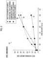
- a graph G2 shown in Fig. 6 shows change in pressure loss in changing the front face wind velocity using the heat exchanger 1 in the present embodiment and the heat exchanger according to the comparative example.
- the graph G2 takes a pressure loss (Pa: pascal) as the vertical axis and takes a front face wind velocity (m/s: millimeters per second) as the horizontal axis.
- a simulation is performed using the heat exchanger 1 according to the present embodiment, the heat exchanger for natural heat exchange, and the heat exchanger for forced heat exchange.
- a simulation result of the heat exchanger 1 according to the present embodiment is shown by a solid line 23.
- a simulation result of the heat exchanger for natural heat exchange is shown by a broken line 24.
- a simulation result of the heat exchanger for forced heat exchange is shown by a one-dot chain line 25.
- a value of the simulation result by natural heat exchange is shown at a position where the front face wind velocity is 0 (zero).
- the pressure loss is 0 (zero).
- a result shows that the pressure loss of the heat exchanger for forced heat exchange is the greatest, and the pressure loss of the heat exchanger for natural heat exchange is the smallest.
- a result shows that the pressure loss of the heat exchanger 1 according to the present embodiment is the greatest, and the heat exchange amount of the heat exchanger for natural heat exchange is the smallest.
- the heat exchanger 1 according to the present embodiment can be used in the heat exchange by the first mode.
- the disposition interval of the fins is greater than the fins of the heat exchanger for forced heat exchange, it is considered that the pressure loss greater than the fins of the heat exchanger for forced heat exchange is generated in the vicinity of 1.5 (m/s) since forming of turbulence with an increase in wind velocity is promoted by the undulating shape of the first fin portion.
- the heat exchanger 1 according to the present embodiment can be used in the heat exchange by the second mode. With this, it has been confirmed that the heat exchanger 1 according to the present embodiment can be used in both the first mode and the second mode.
- control unit 3 is configured to switch between the first mode and the second mode based on the temperature of the heat exchange target. Specifically, the control unit 3 forces air to flow into the first flow path 11 with the fan 2 such that the temperature of the heat exchange target fluid flowing into the second flow path 12 acquired by the second temperature sensor 5 is equal to or lower than a predetermined temperature. In the present embodiment, the control unit 3 acquires a difference between the temperature of air flowing into the first flow path 11 acquired by the first temperature sensor 4 and the temperature of the heat exchange target fluid flowing into the second flow path 12 acquired by the second temperature sensor 5. The control unit 3 adjusts an inflow amount of air by the fan 2 based on the acquired temperature difference between air flowing into the first flow path 11 and the heat exchange target fluid flowing into the second flow path 12.
- control unit 3 increases the inflow amount of air by the fan 2. In a case where the temperature difference between air and the heat exchange target is large, the control unit 3 decreases the inflow amount of air by the fan 2.
- the control unit 3 stops the operation of the fan 2 in a case where the acquired temperature difference between air flowing into the first flow path 11 and the heat exchange target fluid flowing into the second flow path 12 is large, and the needed heat exchange amount is decreased. That is, the control unit 3 performs control for performing heat exchange in the second mode. In performing heat exchange in the second mode, the fan 2 is stopped. Accordingly, air passes through the gap of the fan 2 by natural convection, and flows into the first flow path 11 from the opening 11a on the Z2 direction side.
- Step S1 the control unit 3 determines whether or not an operation input to start automatic switching between natural heat exchange and forced heat exchange is performed. In a case where the operation input to start automatic switching is performed, the process proceeds to Step S2. In a case where the operation input to start automatic switching is not performed, the processing of Step S1 is repeated.
- Step S2 the control unit 3 acquires the temperature of the heat exchange target fluid flowing into the second flow path 12. Specifically, the control unit 3 acquires the temperature of the heat exchange target fluid flowing into the second flow path 12 with the second temperature sensor 5 (see Fig. 1 ).
- Step S3 the control unit 3 determines whether or not the temperature of the heat exchange target fluid is equal to or higher than the predetermined temperature. In a case where the temperature of the heat exchange target fluid is equal to or higher than the predetermined temperature, the process proceeds to Step S4. In a case where the temperature of the heat exchange target fluid is lower than the predetermined temperature, the process proceeds to Step S5.
- Step S4 the control unit 3 performs switching to the second mode. Specifically, the control unit 3 performs switching to the second mode by stopping the fan 2. In a case where the fan 2 is stopped, the processing of Step S4 is omitted. That is, in a case where the operation is performed in the second mode, the processing of Step S4 is omitted.
- Step S5 the control unit 3 performs switching to the first mode. Specifically, the control unit 3 performs switching to the first mode by operating the fan 2.
- the control unit 3 may control the amount of air flowing into the first flow path 11 with the fan 2 based on the temperature of air acquired by the first temperature sensor 4. In a case where the fan 2 is being operated, the processing of Step S5 is omitted.
- Step S6 the control unit 3 determines whether or not an operation input to end automatic switching is performed. In a case where the operation input to end automatic switching is not performed, the process proceeds to Step S2. In a case where the operation input to end automatic switching is performed, the process ends.
- the plurality of fin portions 13a are disposed in parallel at the predetermined intervals p1 in the width direction (Y direction) of the first flow path 11 through which air flows, and are formed to have the undulating shape from one end 11b toward the other end 11c of the first flow path 11 in the width direction of the first flow path 11, the first flow path 11 is configured to be used in both the first mode where heat exchange is performed by forcing air to flow in and the second mode where heat exchange is performed by natural convection.
- the first flow path 11 is used in both the first mode and the second mode, it is possible to restrain the structure of the heat exchanger 1 from being complicated, compared to a configuration in which both flow paths of a flow path for a first mode and a flow path for a second mode are provided.
- the plurality of fin portions 13a have the undulating shape in the width direction (Y direction) of the first flow path 11, it is possible to promote heat transfer with turbulence of flown-in air, compared to a configuration in which the plurality of fin portions 13a do not have the undulating shape. It is also possible to increase a heat transfer area. As a result, it is possible to switch between performing heat exchange by natural convection and heat exchange by forcing air to flow in, and to restrain the structure of the heat exchanger 1 from being complicated.
- the plurality of fin portions 13a are provided continuously from one end 11b to the other end 11c of the first flow path 11, and undulate periodically such that the other end of the first flow path 11 is visible as viewed from one end 11b of the first flow path 11, a through flow path is formed in the first flow path 11. Accordingly, it is possible to suppress an increase in pressure loss of air flowing in the first flow path 11, compared to a configuration in which a through flow path is not formed in the first flow path 11 with the plurality of fin portions 13a. As a result, even in a case where the plurality of fin portions 13a have the undulating shape, it is possible to secure heat exchange efficiency in the second mode where heat exchange is performed by natural convection.
- the plurality of fin portions 13a undulate such that the undulating pattern having the same waveform is repeated at the fixed undulation width W in the width direction (Y direction) of the first flow path 11, and the undulation width W is at least a size less than a half of the interval p1 of the plurality of fin portions 13a.
- the plurality of fin portions 13a undulate such that the undulating pattern having the same waveform is repeated at the fixed undulation width W in the width direction (Y direction) of the first flow path 11. For this reason, it is possible to simplify the structure (shape) of the plurality of fin portions 13a, compared to a configuration in which the undulation width W and/or the undulating pattern of the plurality of fin portions 13a is different halfway.
- the undulation width W of the plurality of fin portions 13a is at least the size less than a half of the disposition interval p1 of the plurality of fin portions 13a.
- the interval p1 of the plurality of fin portions 13a is within a range of equal to or greater than 5 mm and equal to or less than 10 mm, it is possible to dispose the plurality of fin portions 13a at intervals suitable for the second mode where heat exchange is performed by natural convection.
- the disposition interval of the plurality of fin portions 13a is set within the range, while high performance is obtained in the second mode where heat exchange is performed by natural convection of air, the disposition interval is large for the first mode where heat exchange is performed by forcing air to flow in.
- the plurality of fin portions 13a are disposed at the equal intervals over the whole width in the width direction (Y direction) of the first flow path 11.
- control unit 3 Since the control unit 3 is configured to switch between the first mode and the second mode based on the temperature of the heat exchange target, the first mode and the second mode are switched based on the temperature of the heat exchange target. Accordingly, it is possible to suppress an increase in power consumption, for example, compared to a configuration in which heat exchange is constantly performed by the first mode. It is also possible to efficiently perform the heat exchange of the heat exchange target, for example, compared to a configuration in which heat exchange is constantly performed by the second heat exchange mode. As a result, it is possible to efficiently perform the heat exchange of the heat exchange target while suppressing an increase in power consumption.
- the heat exchange target includes the heat exchange target fluid
- the heat exchanger 1 further includes the second flow path 12 through which the heat exchange target fluid flows in a state of being in contact with the separate plate 10 on which the plurality of fin portions 13a are provided.
- the plurality of fin portions 13a are disposed in parallel at the predetermined intervals p1 in the width direction (Y direction) of the first flow path 11 through which air flows, and are formed to have the undulating shape from one end 11b toward the other end 11c of the first flow path 11 in the width direction of the first flow path 11, and in performing the heat exchange of the heat exchange target, the first flow path 11 is configured to be used in both forced heat exchange where the heat exchange of the heat exchange target is performed by forcing air to flow into the first flow path 11 and natural heat exchange where the heat exchange of the heat exchange target is performed by natural convection.
- the fin structure of the heat exchanger 1 capable of switching between performing heat exchange by natural convection and heat exchange by forcing air to flow in, and restraining the structure of the heat exchanger 1 from being complicated, like the above-described heat exchange system 100.
- the plurality of fin portions 13a are disposed at the equal intervals over the whole width in the width direction (Y direction) of the first flow path 11.
- the plurality of fin portions 13a are provided continuously from one end 11b to the other end 11c of the first flow path 11, and undulate periodically such that the other end of the first flow path 11 is visible as viewed from one end 11b of the first flow path 11, a through flow path is formed in the first flow path 11. Accordingly, it is possible to suppress an increase in pressure loss of air flowing in the first flow path 11, compared to a configuration in which a through flow path is not formed in the first flow path 11 with the plurality of fin portions 13a. As a result, even in a case where the plurality of fin portions 13a have the undulating shape, it is possible to secure heat exchange efficiency in the second mode where heat exchange is performed by natural convection.
- the plurality of fin portions 131 according to the second embodiment have the same configuration as the plurality of fin portions 13a according to the above-described first embodiment, except for a case where the maximum inclination angle ⁇ is different.
- the plurality of fin portions 131 undulate such that an undulating pattern having the same waveform is repeated at a fixed undulation width W in the width direction (Y direction) of the first flow path 11.
- the undulating pattern includes a crest portion 11d that protrudes to one side (Y1 direction side) in the width direction of the first flow path 11, a trough portion 11e that protrudes to the other side (Y2 direction side), and a connecting portion 11h that connects the crest portion 11d and the trough portion 11e.
- the maximum inclination angle ⁇ of the connecting portion 11h with respect to a direction (Z direction) from one end 11b side toward the other end 11c side of the first flow path 11 falls within an angle range of equal to or greater than 10 degrees and equal to or less than 30 degrees.
- An example shown in Fig. 8 is a case where the maximum inclination angle ⁇ is 20 degrees.
- each of the crest portion 11d and the trough portion 11e has a shape extending along a direction (Z direction) in which the first flow path 11 extends
- the crest portion 11d and the trough portion 11e may not extend along the direction (Z direction) in which the first flow path 11 extends. That is, the connecting portions 11h may be continuously connected to form an undulating pattern.
- a contact that protrudes to one side (Y1 direction side) may be referred to as a crest portion
- a contact that protrudes to the other side (Y2 direction side) may be referred to as a trough portion.
- a period p2 of undulation is determined by the disposition interval p1 of the fin portions 131 and the maximum inclination angle ⁇ of the connecting portion 11h.
- the heat exchanger 1 is used in both the first mode and the second mode. Accordingly, the period p2 of undulation is set to a range based on a range of the disposition interval p1 of the fin portions 131, a range of the maximum inclination angle ⁇ of the connecting portion 11h, and a heat discharge amount capable of using both the first mode and the second mode.
- a lower limit value of the period p2 of undulation is 0.5 times of the disposition interval p1 of the fin portions 131.
- An upper limit value of the period p2 of undulation is a value in a case where the first flow path 11 is configured such that the other end 11c of the first flow path 11 is visible as viewed from one end 11b of the first flow path 11 in a case where the disposition interval p1 of the fin portions 131 is set to a range of equal to or greater than 5 mm and equal to or less than 10 mm, and the maximum inclination angle ⁇ of the connecting portion 11h is set to be equal to or greater than 10 degrees and equal to or less than 30 degrees.
- Simulation results of a heat exchange amount and a pressure loss in a case where the maximum inclination angle ⁇ of the connecting portion 11h and the period p2 of undulation are changed will be described with reference to Figs. 9 to 11 .
- Simulation results described below are results using a first corrugated fin 130 in which the maximum inclination angle ⁇ of the connecting portion 11h in the heat exchanger 1 is set to 20 degrees, 10 degrees, and 30 degrees, the first corrugated fin 130 in which the maximum inclination angle ⁇ of the connecting portion 11h is 20 degrees, and a period p3 of undulation is a half of the period p2 of undulation, and a first corrugated fin 130 in which a period p4 of undulation is two times of the period p2 of undulation, as shown in Fig.
- the simulation results described below also include a result using a first corrugated fin 140 in which the maximum inclination angle ⁇ of the connecting portion 11h is 0 degrees (a so-called plain fin), as a comparative example.
- the first corrugated fin 140 according to the comparative example has a shape with no undulation in a fin portion.
- connecting portion 11h is disposed such that the maximum inclination angle ⁇ of the connecting portion 11h is 20 degrees.
- the connecting portion 11h is disposed such that the maximum inclination angle ⁇ of the connecting portion 11h is 10 degrees.
- the connecting portion 11h is disposed such that the maximum inclination angle ⁇ of the connecting portion 11h is 30 degrees.
- the period of undulation of the first corrugated fin 130a to the first corrugated fin 130c is the period p2.
- a first corrugated fin 130d is configured such that the maximum inclination angle ⁇ of the connecting portion 11h is 20 degrees, and the period p4 of undulation is a half of the period p2 of undulation.
- a first corrugated fin 130e is configured such that the maximum inclination angle ⁇ of the connecting portion 11h is 20 degrees, and the period p4 of undulation is two times of the period p2 of undulation.
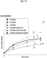
- a graph G3 shown in Fig. 10 takes a heat exchange amount as the vertical axis and takes a front face wind velocity as the horizontal axis.
- a simulation result in a case where the maximum inclination angle ⁇ of the connecting portion 11h is 10 degrees is shown by a one-dot chain line 30.
- a simulation result in a case where the maximum inclination angle ⁇ of the connecting portion 11h is 20 degrees is shown by a solid line 31.
- a simulation result in a case where the maximum inclination angle ⁇ of the connecting portion 11h is 30 degrees is shown by a broken line 32.
- a simulation result in a case where the maximum inclination angle ⁇ of the connecting portion 11h is 20 degrees, and the period p3 of undulation is a half of the period p2 of undulation is shown by a two-dot chain line 33.
- a simulation result in a case where the maximum inclination angle ⁇ of the connecting portion 11h is 20 degrees, and the period p4 of undulation is two times of the period p2 of undulation is shown by a bold line 34.
- a simulation result according to the comparative example is shown by a bold dotted line 35.
- a case where the front face wind velocity is 0 (zero) means heat exchange by the second mode.
- a case where the front face wind velocity is equal to or higher than 0 (zero) means heat exchange by the first mode.
- the simulation result in a case where the maximum inclination angle ⁇ of the connecting portion 11h is 10 degrees shows that the heat exchange amount is increased with respect to the simulation result according to the comparative example.
- the simulation result in a case where the maximum inclination angle ⁇ of the connecting portion 11h is 10 degrees shows that the heat exchange amount is about 1.4 times on average with respect to the simulation result according to the comparative example.
- the simulation result in a case where the maximum inclination angle ⁇ of the connecting portion 11h is 20 degrees shows that, in a case of the first mode, the heat exchange amount is about 1.7 times on average with respect to the simulation result according to the comparative example.
- the simulation result in a case where the maximum inclination angle ⁇ of the connecting portion 11h is 30 degrees shows that, in a case of the first mode, the heat exchange amount is about 2.0 times on average with respect to the simulation result according to the comparative example.
- both the simulation result in a case where the maximum inclination angle ⁇ of the connecting portion 11h is 20 degrees, and the period p3 of undulation is a half of the period p2 of undulation and the simulation result in a case where the maximum inclination angle ⁇ of the connecting portion 11h is 20 degrees, and the period p3 of undulation is a half of the period p2 of undulation show the substantially same heat exchange amount as the simulation result according to the comparative example.
- the simulation result in a case where the period p3 of undulation is a half of the period p2 of undulation show that the heat exchange amount is increased with respect to the simulation result according to the comparative example.
- the simulation result in a case where the period p3 of undulation is a half of the period p2 of undulation shows that, in a case of the first mode, the heat exchange amount is about 1.4 times on average compared to the simulation result according to the comparative example.
- the simulation result in a case where the period p4 of undulation is two times of the period p2 of undulation shows that the heat exchange amount is increased compared to the simulation result according to the comparative example.
- the simulation result in a case where the period p4 of undulation is two times of the period p2 of undulation shows that, in a case of the first mode, the heat exchange amount is about 1.7 times on average compared to the simulation result according to the comparative example.
- the simulation result of the period p4 of undulation shows the heat exchange amount equal to or greater than the simulation result of the period p3 of undulation.
- the heat exchange amount is large compared to the comparative example. It has been confirmed that, in a range of the maximum inclination angle ⁇ of the connecting portion 11h of 10 degrees to 30 degrees, as the angle is increased, the heat exchange amount is increased. It has been confirmed that an influence of the period p2 of undulation on the heat exchange amount is less than an influence of the maximum inclination angle ⁇ of the connecting portion 11h on the heat exchange amount.
- a graph G4 shown in Fig. 11 takes a pressure loss as the vertical axis and takes a front face wind velocity as the horizontal axis.
- a simulation result in a case where the maximum inclination angle ⁇ of the connecting portion 11h is 10 degrees is shown by a one-dot chain line 36.
- a simulation result in a case where the maximum inclination angle ⁇ of the connecting portion 11h is 20 degrees is shown by a solid line 37.
- a simulation result in a case where the maximum inclination angle ⁇ of the connecting portion 11h is 30 degrees is shown by a broken line 38.
- a simulation result in a case where the maximum inclination angle ⁇ of the connecting portion 11h is 20 degrees, and the period p3 of undulation is a half of the period p2 of undulation is shown by a two-dot chain line 39.
- a simulation result in a case where the maximum inclination angle ⁇ of the connecting portion 11h is 20 degrees, and the period p4 of undulation is two times of the period p2 of undulation is shown by a bold line 40.
- a simulation result according to the comparative example is shown by a bold dotted line 41.
- a case where the front face wind velocity is 0 (zero) means heat exchange by the second mode.
- a case where the front face wind velocity is equal to or higher than 0 (zero) means heat exchange by the first mode.
- the simulation result in a case where the maximum inclination angle ⁇ of the connecting portion 11h is 20 degrees shows that, in a case of the first mode, the pressure loss is about 2.8 times on average with respect to the simulation result according to the comparative example.
- the simulation result in a case where the maximum inclination angle ⁇ of the connecting portion 11h is 30 degrees shows that, in a case of the first mode, the pressure loss is about 6.3 times on average with respect to the simulation result according to the comparative example.
- the simulation result in a case where the period p3 of undulation is a half of the period p2 of undulation shows that the pressure loss is increased compared to the simulation result according to the comparative example.
- the simulation result in a case where the period p3 of undulation is a half of the period p2 of undulation shows that, in a case of the first mode, the pressure loss is about 2.2 times compared to the simulation result according to the comparative example.
- the simulation result in a case where the period p4 of undulation is two times of the period p2 of undulation shows that the pressure loss is increased compared to the simulation result according to the comparative example.
- the simulation result in a case where the period p4 of undulation is two times of the period p2 of undulation shows that, in a case of the first mode, the pressure loss is about 2.2 times on average compared to the simulation result according to the comparative example.
- the pressure loss in a case of the first mode is the substantially same in the simulation result of the period p4 of undulation and the simulation result of the period p3 of undulation.
- the maximum inclination angle ⁇ of the connecting portion 11h falls within a range of equal to or greater than 10 degrees and equal to or less than 30 degrees. In a case where the maximum inclination angle ⁇ of the connecting portion 11h is 20 degrees, it has been confirmed that the angle can achieve both a heat discharge amount and heat exchange efficiency. Evaluation of the increasing rate of the heat exchange amount and evaluation of the efficiency of heat exchange are performed based on an amount of change in heat exchange amount and an amount of change in pressure loss with respect to a plane fin in a case where the maximum inclination angle ⁇ of the connecting portion 11h is changed.
- the efficiency of heat exchange is a value that is calculated by dividing the heat exchange amount by the pressure loss.
- the plurality of fin portions 131 undulate such that the undulating pattern having the same waveform is repeated at the fixed undulation width W in the width direction (Y direction) of the first flow path 11.
- the undulating pattern includes the crest portion 11d that protrudes to one side (Y1 direction side) in the width direction of the first flow path 11, the trough portion 11e that protrudes to the other side (Y2 direction side), and the connecting portion 11h that connects the crest portion 11d and the trough portion 11e.
- the maximum inclination angle ⁇ of the connecting portion 11h with respect to the direction (Z direction) from one end 11b side toward the other end 11c side of the first flow path 11 falls within the angle range of equal to or greater than 10 degrees and equal to or less than 30 degrees.
- the present inventors have conducted studies by a simulation and have confirmed that, in a case where the maximum inclination angle ⁇ of the connecting portion 11h falls within the angle range of equal to or greater than 10 degrees and equal to or less than 30 degrees, it is possible to secure high performance in both heat exchange in the first mode and heat exchange in the second mode. In a case where the maximum inclination angle ⁇ of the connecting portion 11h is 20 degrees, it has been confirmed that the angle can achieve both a heat discharge amount and heat exchange efficiency.
- the first flow path 11 may be formed to extend in an oblique direction.
- the heat exchanger 1 may be a fin and tube type heat exchanger other than a plate fin.
- the invention may be applied to a heat sink.
- a plurality of fin portions 61a are provided to extend upward from a base portion 60.
- the base portion 60 is, for example, a metal member having a plate shape.
- a space between a plurality of fin portions 61a forms a first flow path 61.
- the heat sink 6 for example, a semiconductor element or the like is a heat exchange target, and the heat exchange of the semiconductor element or the like is performed by bringing the semiconductor element or the like into contact with the base portion 60.
- the plurality of fin portions 61a are formed to have an undulating shape from one end 11b toward the other end 11c of the first flow path 11 in the width direction (Y direction) of the first flow path 11 of the plurality of fin portions 61a. That is, the first flow path 11 may be divided by a plurality of fins in which an individual first fin portion is provided individually, not by a corrugated fin.
- the first flow path 11 may be formed to extend in the up-down direction (Z direction), the first flow path 11 may be formed to extend in an oblique direction.
- first and second embodiments although an example of a configuration in which the first flow path 11 and the second flow path 12 are perpendicular to each other has been shown, the invention is not limited thereto.
- first flow path 11 and the second flow path 12 may be configured to face each other or the first flow path 11 and the second flow path 12 may be configured to be in parallel with each other.
- first and second embodiments although an example of a configuration in which the first flow path 11 and the second flow path 12 are alternately laminated in the X direction has been shown, the invention is not limited thereto.
- the first flow path 11 and the second flow path 12 may not be alternately laminated.
- the first flow path 11, the first flow path 11, the second flow path 12, the first flow path 11, the first flow path 11, the second flow path 12, and the like may be laminated in this order.
- the invention is not limited thereto.
- the plurality of fin portions 13a may not be disposed at equal intervals over the whole width in the Y direction.
- the plurality of fin portions 13a are not disposed at equal intervals over the whole width in the Y direction, since the structure of the heat exchanger 1 is complicated, it is preferable that the plurality of fin portions 13a (the plurality of fin portions 131) are disposed at equal intervals over the whole width in the Y direction.
- the invention is not limited thereto.
- the undulation width W the plurality of fin portions 13a (the plurality of fin portions 131) may not be fixed. Note that, in a case where the undulation width W of the plurality of fin portions 13a (the plurality of fin portions 131) is not fixed, since the structure of the heat exchanger 1 is complicated, it is preferable that the undulation width W of the plurality of fin portions 13a (the plurality of fin portions 131) is fixed.
- the plurality of fin portions 13a may have an undulating shape in which undulating patterns having different waveforms are combined.
- the plurality of fin portions 13a (the plurality of fin portions 131) have an undulating shape in which undulating patterns having different waveforms are combined, since the structure of the heat exchanger 1 is complicated, it is preferable that the plurality of fin portions 13a (the plurality of fin portions 131) undulate such that the pattern having the same waveform is repeated.
- the interval p1 of the plurality of fin portions 13a (the plurality of fin portions 131) is about 8 mm
- the interval p1 of the plurality of fin portions 13a may be, for example, about 6 mm or may be about 9 mm.
- the interval p1 of the plurality of fin portions 13a is within a range of equal to or greater than 5 mm and equal to or less than 10 mm, the interval p1 of the plurality of fin portions 13a (the plurality of fin portions 131) may have any value.
- the invention is not limited thereto.
- the crest portion 11d and the trough portion 11e may be connected by a connecting portion in which the angle changes continuously.
- the first flow path 11 may be a so-called sine curve shape in top view. In a case where the first flow path 11 has a sine curve shape, a maximum angle of the connecting portion in which the angle continuously changes may fall within an angle range of equal to or greater than 10 degrees and equal to or less than 30 degrees.
- control unit 3 switches between the first mode and the second mode based on the temperature difference between air and the heat exchange target
- the invention is not limited thereto.
- an input reception unit that receives an input of a user may be provided, and the control unit 3 may be configured to switch between the first mode and the second mode based on an input signal of the user.
- the fan 2 may be provided in the opening 11a on the Z1 direction side. That is, in the first mode, heat exchange may be performed by forcing air to flow in from the Z1 direction side with the fan 2, and in the second mode, heat exchange may be performed by making air flow in from the Z2 direction side by natural convection.
- the position where the fan 2 is provided may be any of the opening 11a on the Z1 direction side and the opening 11a on the Z2 direction side.
- the fan 2 may be configured to make air flow into the first flow path 11 by sucking air.
- the fan 2 may not be configured to cover the opening 11a.
- the fan 2 may be connected by a duct, a casing, or the like and may be provided at a remote position.
- the heat exchanger 1 may b configured to perform heating of the heat exchange target.
Landscapes
- Engineering & Computer Science (AREA)
- Physics & Mathematics (AREA)
- Thermal Sciences (AREA)
- Mechanical Engineering (AREA)
- General Engineering & Computer Science (AREA)
- Heat-Exchange Devices With Radiators And Conduit Assemblies (AREA)
Abstract
Description
- The present invention relates to a heat exchange system and a fin structure of a heat exchanger, and in particular, to a heat exchange system and a fin structure of a heat exchanger that perform heat exchange by natural convection and heat exchange by forcing air to flow in.
- In the related art, a heat exchange system and a fin structure of a heat exchanger that perform heat exchange by natural convection and heat exchange by forcing air to flow in are known. Such a heat exchange system is disclosed in, for example,
JP-S61-197416U -
JP-S61-197416U JP-S61-197416U JP-S61-197416U - [PTL 1]
JP-S61-197416U - Here, since the forced convection part disclosed in
JP-S61-197416U JP-S61-197416U JP-S61-197416U - Note that, in a case where the natural convection parts and the forced convection part are formed using a plurality of fins, the plurality of fins are divided into fins used only in heat exchange by natural convection and fins used only in heat exchange by forcing air to flow in. That is, since a part of the plurality of fins is used only in heat exchange by natural convection, and the remaining fins are used only in heat exchange by forcing air to flow in, the number of fins used in heat exchange by natural convection and the number of fins used in heat exchange by forcing air to flow in decrease compared to a configuration in which heat exchange is performed using all fins. For this reason, in a case of switching between performing heat exchange by natural convection and heat exchange by forcing air to flow in, there is a problem in that heat exchange efficiency of respective heat exchange is degraded.
- The invention has been accomplished to solve the problem described above, and an object of the invention is to provide a heat exchange system and a fin structure of a heat exchanger capable of, in a case of switching between performing heat exchange by natural convection and heat exchange by forcing air to flow in, suppressing degradation of heat exchange efficiency of respective heat exchange.
- To achieve the above-described object, the present inventors have conducted intensive studies and have found that a plurality of fin portions in a first flow path of a heat exchanger undulate to be usable in both heat exchange by natural convection and heat exchange by forcing air to flow into the first flow path. Based on the knowledge, a heat exchange system according to a first invention includes a heat exchanger including a base portion that comes into contact with a heat exchange target, and a first flow path which is divided by a plurality of fin portions extending upward from the base portion and through which air flows, a fan that makes air flow into the first flow path, and a control unit that performs control for switching between a first mode where heat exchange of the heat exchange target is performed by forcing air to flow into the first flow path with the fan and a second mode where the heat exchange of the heat exchange target is performed by natural convection, in which the plurality of fin portions are disposed in parallel at predetermined intervals in a width direction of the first flow path, the plurality of fin portions are formed to have an undulating shape from one end toward the other end of the first flow path in the width direction of the first flow path, and the first flow path is configured to be used in both the first mode and the second mode.
- In the heat exchanger according to the invention, as described above, the plurality of fin portions are disposed in parallel at the predetermined intervals in the width direction of the first flow path through which air flows, and are formed to have the undulating shape from one end toward the other end of the first flow path in the width direction of the first flow path, and the first flow path is configured to be used in both the first mode where the heat exchange is performed by forcing air to flow in and the second mode where the heat exchange is performed by the natural convection. With this, since the first flow path is used in both the first mode and the second mode, it is possible to suppress a decrease in the number of fin portions used in each heat exchange mode, compared to a configuration in which fin portions including both fin portions used only in the first mode and fin portions used only in the second mode are provided in the first flow path. Since the plurality of fin portions have the undulating shape in the width direction of the first flow path, it is possible to promote heat transfer with turbulence of flown-in air, compared to a configuration in which the plurality of fin portions do not have an undulating shape. It is possible to increase a heat transfer area without narrowing the disposition interval of the fin portions. As a result, in a case of switching between performing heat exchange by natural convection and heat exchange by forcing air to flow in, it is possible to suppress degradation of heat exchange efficiency of respective heat exchange.
- In this case, preferably, the plurality of fin portions are provided continuously from the one end to the other end of the first flow path and undulate periodically such that the other end of the first flow path is visible as viewed from the one end of the first flow path. With this configuration, a through flow path is formed in the first flow path. Accordingly, it is possible to suppress an increase in pressure loss of air flowing in the first flow path, compared to a configuration in which a through flow path is not formed in the first flow path with the plurality of fin portions. As a result, even in a case where the plurality of fin portions have the undulating shape, it is possible to secure heat exchange efficiency in the second mode where heat exchange is performed by natural convection.
- In the above-described configuration in which the plurality of fin portions are provided continuously from the one end to the other end of the first flow path and undulate periodically such that the other end of the first flow path is visible as viewed from the one end of the first flow path, preferably, the plurality of fin portions undulate such that an undulating pattern of the same waveform is repeated at a fixed undulation width in the width direction of the first flow path, and the undulation width is at least a size less than a half of a disposition interval of the plurality of fin portions. With this configuration, since the plurality of fin portions undulate such that the undulating pattern of the same waveform is repeated at the fixed undulation width in the width direction of the first flow path, it is possible to simplify the structure (shape) of the plurality of fin portions, compared to a configuration in which the undulation width and/or the undulating pattern of the plurality of fin portions is different halfway. Since the undulation width of the plurality of fin portions is at least the size less than a half of the disposition interval of the plurality of fin portions, it is possible to make a configuration in which the other end of the first flow path is visible as viewed from the one end of the first flow path, and to secure heat exchange efficiency in the second mode. As a result, it is possible to achieve both the simplification of the structure (shape) of the plurality of fin portions and securing of heat exchange efficiency in the second mode.
- In the above-described configuration in which the plurality of fin portions are provided continuously from the one end to the other end of the first flow path and undulate periodically such that the other end of the first flow path is visible as viewed from the one end of the first flow path, preferably, the plurality of fin portions undulate such that an undulating pattern of the same waveform is repeated at a fixed undulation width in the width direction of the first flow path, the undulating pattern includes a crest portion that protrudes to one side, a trough portion that protrudes to the other side, and a connecting portion that connects the crest portion and the trough portion, in the width direction of the first flow path, and a maximum inclination angle of the connecting portion with respect to a direction from one end side to the other end side of the first flow path is within an angle range of equal to or greater than 10 degrees and equal to or less than 30 degrees.
- Here, in a case where a period of undulation of the first flow path is fixed, as the maximum inclination angle of the connecting portion is greater, the effect of turbulence in the first flow path is increased, and it is possible to further increase a heat transfer area. As the heat transfer area of the first flow path is increased, it is possible to improve heat exchange performance by the first mode where air is forced to flow in. Note that, in a case where the maximum inclination angle of the connecting portion is large, since a pressure loss in the first flow path increases, heat exchange efficiency in the second mode where heat exchange is performed by natural convection of air is degraded. In a case where the period of undulation of the first flow path is fixed, as the maximum inclination angle of the connecting portion is smaller, since the effect of turbulence of the first flow path is decreased, and the heat transfer area is decreased, heat exchange performance by the first mode is degraded. Note that, in a case where the maximum inclination angle of the connecting portion is small, since the pressure loss of the first flow path decreases, heat exchange efficiency in the second mode is improved. Accordingly, the present inventors have conducted studies and have confirmed that, in a case where the maximum inclination angle of the connecting portion falls within an angle range of equal to or greater than 10 degrees and equal to or less than 30 degrees, it is possible to secure high performance in any of the heat exchange in the first mode and the heat exchange in the second mode.
- In the heat exchange system according to the first invention described above, preferably, a disposition interval of the plurality of fin portions is within a range of equal to or greater than 5 mm and equal to or less than 10 mm. With this configuration, it is possible to dispose the plurality of fin portions at intervals suitable for the second mode where heat exchange is performed by natural convection. In a case where the disposition interval of the plurality of fin portions is set within this range, while high performance is obtained in the second mode where heat exchange is performed by natural convection of air, the disposition interval is large for the first mode where heat exchange is performed by forcing air to flow in. That is, in a case where the plurality of fin portions are disposed at the disposition intervals within the range of equal to or greater than 5 mm and equal to or less than 10 mm, heat exchange performance by the first mode is degraded. Accordingly, the present inventors have conducted studies and have confirmed that the plurality of fin portions have the undulating shape, such that it is also possible to secure high performance in heat exchange by the first mode even in a case where the plurality of fin portions are disposed at the disposition intervals within the range of equal to or greater than 5 mm and equal to or less than 10 mm.
- In the heat exchanger according to the invention described above, preferably, the plurality of fin portions are disposed at equal intervals over a whole width in the width direction of the first flow path. With this configuration, since the plurality of fin portions are disposed at the equal intervals over the whole width in the width direction of the first flow path, it is possible to perform heat exchange by the first mode and heat exchange by the second mode using the whole first flow path, unlike a configuration in which a part where heat exchange is performed by the first mode and a part where heat exchange is performed by the second mode are formed by changing the disposition interval of the plurality of fin portions. As a result, it is possible to suppress degradation of heat exchange efficiency of each heat exchange mode.
- In the heat exchange system according to the first invention described above, preferably, the control unit is configured to switch between the first mode and the second mode based on a temperature of the heat exchange target. With this configuration, since the first mode and the second mode are switched based on the temperature of the heat exchange target, it is possible to suppress an increase in power consumption, for example, compared to a configuration in which heat exchange is constantly by the first mode. It is possible to efficiently perform the heat exchange of the heat exchange target, for example, compared to a configuration in which heat exchange is constantly performed by the second mode. As a result, it is possible to efficiently perform the heat exchange of the heat exchange target while suppressing an increase in power consumption.
- In the heat exchange system according to the first invention described above, preferably, the heat exchange target includes a heat exchange target fluid, and the heat exchanger further includes a second flow path through which the heat exchange target fluid flows in a state of being in contact with the base portion where a plurality of fin portions are provided. With this configuration, it is possible to easily bring the base portion in which the plurality of fin portions are provided, and the heat exchange target fluid into contact with each other by making the heat exchange target fluid flow into the second flow path, and to easily perform the heat exchange of the heat exchange target fluid.
- A fin structure of a heat exchanger according to a second invention includes a base portion that comes into contact with a heat exchange target, and a plurality of fin portions provided to extend upward from the base portion, in which the plurality of fin portions form a first flow path through which air flows, have an undulating shape from one end toward the other end of the formed first flow path in a width direction of the first flow path, are disposed at equal intervals over a whole width in the width direction of the first flow path, are provided continuously from the one end to the other end of the first flow path, and, undulate periodically such that the other end of the first flow path is visible as viewed from the one end of the first flow path, and in performing heat exchange of the heat exchange target, the first flow path is configured to be used in both forced heat exchange where the heat exchange of the heat exchange target is performed by forcing air to flow into the first flow path and natural heat exchange where the heat exchange of the heat exchange target is performed by natural convection.
- In the fin structure of a heat exchanger according to the second invention, as described above, the plurality of fin portions are disposed in parallel at the predetermined intervals in the width direction of the first flow path, and have the undulating shape from one end toward the other end of the first flow path in the width direction of the first flow path. With this, like the heat exchange system according to the first invention described above, in a case of switching between performing heat exchange by natural convection and heat exchange by forcing air to flow in, it is possible to provide the fin structure of the heat exchanger capable of suppressing degradation of heat exchange efficiency of respective heat exchange. In the fin structure of the heat exchanger according to the second invention, the plurality of fin portions are disposed at the equal intervals over the whole width in the width direction of the first flow path. With this, since the plurality of fin portions are disposed at the equal intervals over the whole width in the width direction of the first flow path, it is possible to perform heat exchange by the first mode and heat exchange by the second mode using the whole first flow path, unlike a configuration in which a part where heat exchange is performed by the first mode and a part where heat exchange is performed by the second mode are formed by changing the disposition interval of the plurality of fin portions halfway of the first flow path. As a result, it is possible to suppress degradation of heat exchange efficiency of each heat exchange mode.
- In the fin structure of the heat exchanger according to the second invention, the plurality of fin portions are provided continuously from one end to the other end of the first flow path, and undulate periodically such that the other end of the first flow path is visible as viewed from one end of the first flow path. With this, a through flow path is formed in the first flow path. Accordingly, it is possible to suppress an increase in pressure loss of air flowing in the first flow path, compared to a configuration in which a through flow path is not formed in the first flow path with the plurality of fin portions. As a result, even in a case where the plurality of fin portions have the undulating shape, it is possible to secure heat exchange efficiency in the second mode where heat exchange is performed by natural convection.
- According to the invention, as described above, in a case of switching between performing heat exchange by natural convection and heat exchange by forcing air to flow in, it is possible to suppress degradation of heat exchange efficiency of respective heat exchange.
-
-
Fig. 1 is a perspective view showing a heat exchange system according to a first embodiment. -
Fig. 2 is a perspective view showing a base portion and a plurality of fin portions of a heat exchanger according to the first embodiment. -
Fig. 3 is a schematic view as a first flow path according to the first embodiment is viewed from an X1 direction. -
Fig. 4 is a schematic view as the first flow path according to the first embodiment is viewed from a Z1 direction. -
Fig. 5 is a simulation result showing change in heat exchange amount in changing a front face wind velocity using the heat exchanger according to the first embodiment and a heat exchanger according to a comparative example. -
Fig. 6 is a simulation result showing change in pressure loss in changing the front face wind velocity using the heat exchanger according to the first embodiment and the heat exchanger according to the comparative example. -
Fig. 7 is a flowchart illustrating processing in which the heat exchange system according to the first embodiment switches between a first mode and a second mode. -
Fig. 8 is a schematic view illustrating a maximum inclination angle of a connecting portion according to a second embodiment. -
Fig. 9 is a schematic view (A) to a schematic view (F) illustrating a heat exchanger used in a simulation according to the second embodiment and a heat exchanger of a comparative example. -
Fig. 10 is a simulation result showing change in heat exchange amount in changing a front face wind velocity in the heat exchanger according to the second embodiment in which an angle of a connecting portion of a first flow path and a period are made different. -
Fig. 11 is a simulation result showing change in pressure loss in changing the front face wind velocity in the heat exchanger according to the second embodiment in which the angle of the connecting portion of the first flow path and the period are made different. -
Fig. 12 is a perspective view showing a base portion and a plurality of fin portions of a heat exchanger according to a modification example. - Hereinafter, embodiments of the invention will be described based on the drawings.
- First, an overall configuration of a
heat exchange system 100 according to the present embodiment will be described with reference toFigs. 1 to 4 . - As shown in
Fig. 1 , aheat exchange system 100 includes aheat exchanger 1, afan 2, acontrol unit 3, afirst temperature sensor 4, and asecond temperature sensor 5. In the present specification, an up-down direction is represented as a Z direction, an up direction is represented as a Z1 direction, and a down direction is represented as a Z2 direction. Two directions perpendicular to each other within a plane perpendicular to the Z direction are represented as an X direction and a Y direction. In the X direction, one side is represented as an X1 direction, and the other side is represented as an X2 direction. In the Y direction, one side is represented as a Y1 direction, and the other side is represented as a Y2 direction. - The
heat exchanger 1 has an opening that is an inlet or an outlet of a fluid and is configured to make the fluid flow to perform heat exchange.Fig. 1 shows an example where theheat exchanger 1 is a plate fin type heat exchanger. The plate fintype heat exchanger 1 has a rectangular parallelepiped shape including a surface (side surface) where the opening is formed. Theheat exchanger 1 has a flow path for making the fluid flow inside and is configured to perform heat exchange in a process of making the fluid flow. The heat exchange that is performed by theheat exchanger 1 includes cooling and heating. In the present embodiment, a case where theheat exchanger 1 performs cooling of a heat exchange target will be described. - The
heat exchanger 1 has a structure in whichseparate plates 10, firstcorrugated fins 13, and secondcorrugated fins 14 are laminated. First side bars 15 are disposed on in outer peripheral portions of each firstcorrugated fin 13. Second side bars 16 are disposed in outer peripheral portions of each secondcorrugated fin 14. The firstcorrugated fins 13, the secondcorrugated fins 14, theseparate plates 10, the first side bars 15, and the second side bars 16 are bonded by brazing, whereby theheat exchanger 1 is configured. Eachseparate plate 10 is an example of a "base portion" in the claims. - A
first flow path 11 is divided by theseparate plate 10, thefirst side bar 15, and theseparate plate 10, and is configured with each layer where the firstcorrugated fin 13 is disposed inside. Air as the fluid flows in thefirst flow path 11. In the present embodiment, thefirst flow path 11 is formed to extend in the up-down direction (Z direction). In the example shown inFig. 1 , the Y direction is a width direction of thefirst flow path 11. The X direction is a height direction of thefirst flow path 11. - A second flow path 12 is divided by the
separate plate 10, thesecond side bar 16, and theseparate plate 10, and is configured with each layer where the secondcorrugated fin 14 is disposed inside. A heat exchange target fluid flows in the second flow path 12 in a state of being in contact with theseparate plate 10. - In the present embodiment, the
heat exchanger 1 performs heat exchange between air and the heat exchange target fluid flowing in thefirst flow path 11 and the second flow path 12, respectively. In the example shown inFig. 1 , air flows into thefirst flow path 11 from a Z2 direction side and flows out from a Z1 direction side. The heat exchange target fluid flows into the second flow path 12 from a Y1 direction side and flows out from a Y2 direction side. - The
separate plate 10 has a rectangular shape. Theseparate plate 10 is configured to come into contact with the heat exchange target. The heat exchange target includes the heat exchange target fluid. The heat exchange target fluid includes, for example, oil or a refrigerant. - The
heat exchanger 1 has a structure in which thefirst flow path 11 and the second flow path 12 are alternately laminated such that thefirst flow path 11 and the second flow path 12 are perpendicular to each other. Thefirst flow path 11 and the second flow path 12 are laminated in the X direction. - In the example of
Fig. 1 , theheat exchanger 1 includessurfaces 1a where anopening 11a of thefirst flow path 11 is formed andsurfaces 1b where anopening 12a of the second flow path 12 is formed. Theopening 11a of thefirst flow path 11 is formed in bothsurfaces 1a in the Z direction and theopening 12a of the second flow path 12 is formed in bothsurfaces 1b on a Y direction side perpendicular to thesurface 1a. Theopening 11a is formed in a portion of thesurface 1a excluding the second flow path 12. Theopening 12a is formed in a portion of thesurface 1b excluding thefirst flow path 11. - The
fan 2 is configured to make air flow into thefirst flow path 11 under the control of thecontrol unit 3. Thefan 2 is configured to make air flow into thefirst flow path 11 from theopening 11a on the Z2 direction side. Thefan 2 is provided in a state of being in contact with thesurface 1a on the Z2 direction side to close theopening 11a on the Z2 direction side. Thefan 2 includes, for example, a blower that blows air into thefirst flow path 11. - The
control unit 3 is configured to perform control for switching between a first mode where the heat exchange of the heat exchange target is performed by forcing air to flow into thefirst flow path 11 with thefan 2 and a second mode where the heat exchange of the heat exchange target is performed by natural convection. Thecontrol unit 3 is configured to acquire a temperature difference between air and the heat exchange target based on a temperature of air acquired by thefirst temperature sensor 4 and a temperature of the heat exchange target acquired by thesecond temperature sensor 5. In the present embodiment, thefirst flow path 11 is configured to be used in both the first mode and the second mode. Thecontrol unit 3 includes, for example, a central processing unit (CPU), a read only memory (ROM), and a random access memory (RAM). - The
first temperature sensor 4 is configured to acquire the temperature of air. Thefirst temperature sensor 4 is provided in the vicinity of theopening 11a on the Z2 direction side and acquires the temperature of air flowing into thefirst flow path 11. Thefirst temperature sensor 4 is configured to output the acquired temperature of air to thecontrol unit 3. - The
second temperature sensor 5 is configured to acquire the temperature of the heat exchange target. Thesecond temperature sensor 5 is provided in the vicinity of theopening 12a on the Y1 direction side and acquires the temperature of the heat exchange target flowing into the second flow path 12. Thesecond temperature sensor 5 is configured to output the acquired temperature of the heat exchange target to thecontrol unit 3. - Next, the configuration of the
first flow path 11 will be described with reference toFig. 2 . As shown inFig. 2 , thefirst flow path 11 is formed by theseparate plate 10 and one firstcorrugated fin 13. In an example ofFig. 2 , for convenience, theseparate plate 10 on an X1 direction side is not shown. - As shown in
Fig. 2 , theseparate plate 10 extends along a YZ plane. In the example shown inFig. 2 , theseparate plate 10 has long sides disposed in an orientation along the Z direction. The firstcorrugated fin 13 includes a plurality offin portions 13a, a first connectingportion 13b, and a second connectingportion 13c. The plurality offin portions 13a are provided to extend upward from theseparate plate 10. The plurality offin portions 13a are provided to extend upward from theseparate plate 10 from an X2 direction side toward the X1 direction side. The plurality offin portions 13a are connected by the first connectingportion 13b on the X1 direction side. The plurality offin portions 13a are connected by the second connectingportion 13c on the X2 direction side. The first connectingportion 13b and the second connectingportion 13c are alternately provided in the Y direction. Thefirst flow path 11 is divided by the plurality offin portions 13a provided to extend upward from theseparate plate 10. - As shown in
Fig. 2 , the plurality offin portions 13a are disposed in parallel at predetermined intervals p1 in the width direction (Y direction) of thefirst flow path 11. The plurality offin portions 13a are formed to have an undulating shape from oneend 11b toward theother end 11c of thefirst flow path 11 in the width direction (Y direction) of thefirst flow path 11. Specifically, the plurality offin portions 13a are disposed at the intervals p1 and at equal intervals over the whole width in the width direction (Y direction) of thefirst flow path 11. The interval p1 of the plurality offin portions 13a is a distance of a gap portion of thefin portions 13a excluding a plate thickness. The undulating shape is a shape in which acrest portion 11d and atrough portion 11e are alternately repeated in a direction (Z direction) from oneend 11b toward theother end 11c of thefirst flow path 11. - In the present embodiment, the plurality of
fin portions 13a undulate in a period p2. The period p2 is a distance between thecrest portions 11d on the Y1 direction side of thefin portion 13a in the Z direction. - As shown in
Fig. 3 , the plurality offin portions 13a undulate such that an undulating pattern of the same waveform is repeated at a fixed undulation width W in the width direction (Y direction) of thefirst flow path 11. The undulation width W is a distance between thecrest portion 11d on the Y1 direction side of thefin portion 13a and thetrough portion 11e on the Y1 direction side of thefin portion 13a. The undulating pattern means a unit of repetition in the Z direction in a case where the plurality offin portions 13a undulate. - In the present embodiment, since the undulation width W is fixed, the distance between a
trough portion 11g on the Y2 direction side of thefin portion 13a and acrest portion 11f on the Y2 direction side of thefin portion 13a is equal to the distance between thecrest portion 11d on the Y1 direction side of thefin portion 13a and thetrough portion 11e on the Y1 direction side of thefin portion 13a. -
Fig. 4 is a schematic view as thefirst flow path 11 is viewed from the Z1 direction side.Fig. 4 shows thefin portions 13a, the first connectingportion 13b, the second connectingportions 13c, asurface 110a in thecrest portion 11d (seeFig. 3 ) of thefin portion 13a that is visible from the Z2 direction side, asurface 110b in thetrough portion 11e (seeFig. 3 ) of thefin portion 13a that is visible from the Z2 direction side, asurface 110c in thecrest portion 11f (seeFig. 3 ) of thefin portion 13a that is visible from the Z2 direction side, and asurface 110d in thetrough portion 11g (seeFig. 3 ) of thefin portion 13a that is visible from the Z2 direction side.Fig. 4 is not a sectional view, and theseparate plate 10, thefin portions 13a, the first connectingportion 13b, the second connectingportions 13c, and thesurface 110a to thesurface 110d are hatched differently for ease of identification. - As shown in
Fig. 4 , the plurality offin portions 13a undulate periodically such that theother end 11c of thefirst flow path 11 is visible as viewed from oneend 11b of thefirst flow path 11. Specifically, the undulation width W is at least a size less than a half of the interval p1 of the plurality offin portions 13a. In other words, the plurality offin portions 13a undulate such that a distance D between anend portion 111a on the Y2 direction side of thesurface 110b and anend portion 111b on the Y1 direction side of thesurface 110c is not 0 (zero). That is, the plurality offin portions 13a undulate such that a size obtained by adding a width W1 in the Y direction of thesurface 110b and a width W2 in the Y direction of thesurface 110c of each of the plurality offin portions 13a is smaller than the interval p1 of the plurality offin portions 13a. In the present embodiment, the interval p1 of the plurality offin portions 13a is within a range of equal to or greater than 5 mm and equal to or less than 10 mm. In the present embodiment, the interval p1 of the plurality offin portions 13a is, for example, about 8 mm. In the present embodiment, a thickness of the first fin portion is about 0.25 mm. - In the present embodiment, in performing the heat exchange of the heat exchange target, the
first flow path 11 is used in both forced heat exchange where the heat exchange of the heat exchange target is performed by forcing air to flow into thefirst flow path 11 and natural heat exchange where the heat exchange of the heat exchange target is performed by natural convection. Hereinafter, it has been confirmed that theheat exchanger 1 according to the present embodiment can be used in both forced heat exchange and natural heat exchange by performing a simulation using theheat exchanger 1 according to the present embodiment and the comparative example. A simulation result described below is obtained by cooling the heat exchange target using theheat exchanger 1 according to the embodiment and a comparative example. - A graph G1 shown in
Fig. 5 shows change in heat exchange amount in changing a front face wind velocity using theheat exchanger 1 in the present embodiment and a heat exchanger according to the comparative example. The graph G1 takes a heat exchange amount (kW: kilowatt) as the vertical axis and takes a front face wind velocity (m/s: millimeters per second) as the horizontal axis. The front face wind velocity is a wind velocity of air in theopening 11a in flowing into theheat exchanger 1, and is not a wind velocity of air that flows among the plurality offin portions 13a. The simulation result shown in the graph G1 is a result obtained by performing a simulation in a state where a temperature of air in theopening 11a in flowing into thefirst flow path 11 is fixed at 30 degrees, and a temperature of the heat exchange target fluid that flows in the second flow path 12 is fixed at 85 degrees. - In the graph G1, as an example, a heat exchanger in which fins having a thickness of about 0.25 mm are disposed at disposition intervals of about 8 mm is used. As a comparative example, a heat exchanger for natural heat exchange that includes fins disposed suitably for natural heat exchange and a heat exchanger for forced heat exchange that includes fins suitable for forced heat exchange are used. The heat exchanger for natural heat exchange is, for example, a heat exchanger in which fins having a thickness of about 0.25 mm are disposed at disposition intervals of about 8 mm. The heat exchanger for forced heat exchange is, for example, a heat exchanger in which fins having a thickness of about 0.25 mm are disposed at disposition intervals of about 3.4 mm. Both the fins of the heat exchanger for natural heat exchange and the fins of the heat exchanger for forced heat exchange do not have an undulating shape from one end toward the other end of the first flow path in the Y direction. The fins of the heat exchanger for natural heat exchange and the fins of the heat exchanger for forced heat exchange are configured with plain type corrugated fins.
- In the graph G1, a simulation result of the
heat exchanger 1 according to the present embodiment is shown by asolid line 20. A simulation result of the heat exchanger for natural heat exchange is shown by abroken line 21. A simulation result of the heat exchanger for forced heat exchange is shown by a one-dot chain line 22. In the graph G1, for convenience, a value of a simulation result by natural heat exchange is shown at a position where the front face wind velocity is 0 (zero). - As shown in the graph G1, in a case where the front face wind velocity is 0 (zero), a result shows that the heat exchange amount of the heat exchanger for natural heat exchange is the greatest, and the heat exchange amount of the
heat exchanger 1 according to the present embodiment is the second greatest, and the heat exchange amount of the heat exchanger for forced heat exchange is the smallest. A case where the front face wind velocity is 0 (zero) is heat exchange by natural convection. That is, a case where the front face wind velocity is 0 (zero) is heat exchange by the second mode. A case where the front face wind velocity is equal to or higher than 0 (zero) is heat exchange by the first mode. - As shown in the graph G1, in a case where the front face wind velocity increases to 0.5 (m/s), the heat exchange amount of the heat exchanger for forced heat exchange is the greatest, and the heat exchange amount of the heat exchanger for natural heat exchange is the smallest. In a range of the front face wind velocity of 0.5 (m/s) to 2.0 (m/s), the heat exchange amount of the heat exchanger for forced heat exchange is the greatest, and the heat exchange amount of the heat exchanger for natural heat exchange is the smallest. In a case where the front face wind velocity increases higher than 2.0 (m/s), the heat exchange amount of the
heat exchanger 1 according to the present embodiment is the greatest, and the heat exchange amount of the heat exchanger for natural heat exchange is the smallest. Specifically, in a case where the front face wind velocity is 2.0 (m/s), a ratio of the heat exchange amount of theheat exchanger 1 according to the present embodiment to the heat exchange amount of the heat exchanger for forced heat exchange is about 96%. A ratio of the heat exchange amount of the heat exchanger for natural heat exchange to the heat exchange amount of the heat exchanger for forced heat exchange is about 39%. In a case where the front face wind velocity is 3.0 (m/s), a ratio of the heat exchange amount of theheat exchanger 1 according to the present embodiment to the heat exchange amount of the heat exchanger for forced heat exchange is about 112%. A ratio of the heat exchange amount of the heat exchanger for natural heat exchange to the heat exchange amount of the heat exchanger for forced heat exchange is about 40%. That is, it has been confirmed that theheat exchanger 1 according to the present embodiment has heat exchange efficiency equal to or higher than the heat exchanger for forced heat exchange in the heat exchange by the first mode. - With the
heat exchanger 1 according to the present embodiment, in the heat exchange by the second mode, a ratio of the heat exchange amount of theheat exchanger 1 according to the present embodiment to the heat exchange amount of the heat exchanger for natural heat exchange is about 93%. A ratio of the heat exchange amount of the heat exchanger for forced heat exchange to the heat exchange amount of the heat exchanger for natural heat exchange is about 39%. That is, it has been confirmed that theheat exchanger 1 according to the present embodiment has heat exchange efficiency equal to the heat exchanger for natural heat exchange in the heat exchange by the second mode. With this, it has been confirmed that theheat exchanger 1 according to the present embodiment can be used in both the first mode and the second mode. - A graph G2 shown in
Fig. 6 shows change in pressure loss in changing the front face wind velocity using theheat exchanger 1 in the present embodiment and the heat exchanger according to the comparative example. The graph G2 takes a pressure loss (Pa: pascal) as the vertical axis and takes a front face wind velocity (m/s: millimeters per second) as the horizontal axis. In the graph G2, a simulation is performed using theheat exchanger 1 according to the present embodiment, the heat exchanger for natural heat exchange, and the heat exchanger for forced heat exchange. - In the graph G2, a simulation result of the
heat exchanger 1 according to the present embodiment is shown by asolid line 23. A simulation result of the heat exchanger for natural heat exchange is shown by abroken line 24. A simulation result of the heat exchanger for forced heat exchange is shown by a one-dot chain line 25. In the graph G2, for convenience, a value of the simulation result by natural heat exchange is shown at a position where the front face wind velocity is 0 (zero). - As shown in the graph G2, in a case where the front face wind velocity is 0 (zero), in all heat exchangers, the pressure loss is 0 (zero). In a range of the front face wind velocity to 1.5 (m/s), a result shows that the pressure loss of the heat exchanger for forced heat exchange is the greatest, and the pressure loss of the heat exchanger for natural heat exchange is the smallest. In a range of the front face wind velocity higher than 1.5 (m/s), a result shows that the pressure loss of the
heat exchanger 1 according to the present embodiment is the greatest, and the heat exchange amount of the heat exchanger for natural heat exchange is the smallest. From the results, it has been confirmed that, in a case where the front face wind velocity is high, since the pressure loss is increased, and the heat exchange efficiency is also increased, theheat exchanger 1 according to the present embodiment can be used in the heat exchange by the first mode. In theheat exchanger 1 according to the present embodiment, although the disposition interval of the fins is greater than the fins of the heat exchanger for forced heat exchange, it is considered that the pressure loss greater than the fins of the heat exchanger for forced heat exchange is generated in the vicinity of 1.5 (m/s) since forming of turbulence with an increase in wind velocity is promoted by the undulating shape of the first fin portion. It has been confirmed that, in a case where the front face wind velocity is low, since the pressure loss is small like the heat exchanger for natural heat exchange, theheat exchanger 1 according to the present embodiment can be used in the heat exchange by the second mode. With this, it has been confirmed that theheat exchanger 1 according to the present embodiment can be used in both the first mode and the second mode. - In the present embodiment, the
control unit 3 is configured to switch between the first mode and the second mode based on the temperature of the heat exchange target. Specifically, thecontrol unit 3 forces air to flow into thefirst flow path 11 with thefan 2 such that the temperature of the heat exchange target fluid flowing into the second flow path 12 acquired by thesecond temperature sensor 5 is equal to or lower than a predetermined temperature. In the present embodiment, thecontrol unit 3 acquires a difference between the temperature of air flowing into thefirst flow path 11 acquired by thefirst temperature sensor 4 and the temperature of the heat exchange target fluid flowing into the second flow path 12 acquired by thesecond temperature sensor 5. Thecontrol unit 3 adjusts an inflow amount of air by thefan 2 based on the acquired temperature difference between air flowing into thefirst flow path 11 and the heat exchange target fluid flowing into the second flow path 12. That is, in a case where the temperature difference between air and the heat exchange target is small, thecontrol unit 3 increases the inflow amount of air by thefan 2. In a case where the temperature difference between air and the heat exchange target is large, thecontrol unit 3 decreases the inflow amount of air by thefan 2. - The
control unit 3 stops the operation of thefan 2 in a case where the acquired temperature difference between air flowing into thefirst flow path 11 and the heat exchange target fluid flowing into the second flow path 12 is large, and the needed heat exchange amount is decreased. That is, thecontrol unit 3 performs control for performing heat exchange in the second mode. In performing heat exchange in the second mode, thefan 2 is stopped. Accordingly, air passes through the gap of thefan 2 by natural convection, and flows into thefirst flow path 11 from theopening 11a on the Z2 direction side. - Next, processing in which the
control unit 3 according to the present embodiment switches between the first mode and the second mode will be described with reference toFig. 7 . - In Step S1, the
control unit 3 determines whether or not an operation input to start automatic switching between natural heat exchange and forced heat exchange is performed. In a case where the operation input to start automatic switching is performed, the process proceeds to Step S2. In a case where the operation input to start automatic switching is not performed, the processing of Step S1 is repeated. - In Step S2, the
control unit 3 acquires the temperature of the heat exchange target fluid flowing into the second flow path 12. Specifically, thecontrol unit 3 acquires the temperature of the heat exchange target fluid flowing into the second flow path 12 with the second temperature sensor 5 (seeFig. 1 ). - In Step S3, the
control unit 3 determines whether or not the temperature of the heat exchange target fluid is equal to or higher than the predetermined temperature. In a case where the temperature of the heat exchange target fluid is equal to or higher than the predetermined temperature, the process proceeds to Step S4. In a case where the temperature of the heat exchange target fluid is lower than the predetermined temperature, the process proceeds to Step S5. - In Step S4, the
control unit 3 performs switching to the second mode. Specifically, thecontrol unit 3 performs switching to the second mode by stopping thefan 2. In a case where thefan 2 is stopped, the processing of Step S4 is omitted. That is, in a case where the operation is performed in the second mode, the processing of Step S4 is omitted. - In a case where the process proceeds from Step S3 to Step S5, in Step S5, the
control unit 3 performs switching to the first mode. Specifically, thecontrol unit 3 performs switching to the first mode by operating thefan 2. Thecontrol unit 3 may control the amount of air flowing into thefirst flow path 11 with thefan 2 based on the temperature of air acquired by thefirst temperature sensor 4. In a case where thefan 2 is being operated, the processing of Step S5 is omitted. - In Step S6, the
control unit 3 determines whether or not an operation input to end automatic switching is performed. In a case where the operation input to end automatic switching is not performed, the process proceeds to Step S2. In a case where the operation input to end automatic switching is performed, the process ends. - In the first embodiment, the following effects can be obtained.
- In the first embodiment, as described above, the plurality of
fin portions 13a are disposed in parallel at the predetermined intervals p1 in the width direction (Y direction) of thefirst flow path 11 through which air flows, and are formed to have the undulating shape from oneend 11b toward theother end 11c of thefirst flow path 11 in the width direction of thefirst flow path 11, thefirst flow path 11 is configured to be used in both the first mode where heat exchange is performed by forcing air to flow in and the second mode where heat exchange is performed by natural convection. Thus, since thefirst flow path 11 is used in both the first mode and the second mode, it is possible to restrain the structure of theheat exchanger 1 from being complicated, compared to a configuration in which both flow paths of a flow path for a first mode and a flow path for a second mode are provided. Since the plurality offin portions 13a have the undulating shape in the width direction (Y direction) of thefirst flow path 11, it is possible to promote heat transfer with turbulence of flown-in air, compared to a configuration in which the plurality offin portions 13a do not have the undulating shape. It is also possible to increase a heat transfer area. As a result, it is possible to switch between performing heat exchange by natural convection and heat exchange by forcing air to flow in, and to restrain the structure of theheat exchanger 1 from being complicated. - Since the plurality of
fin portions 13a are provided continuously from oneend 11b to theother end 11c of thefirst flow path 11, and undulate periodically such that the other end of thefirst flow path 11 is visible as viewed from oneend 11b of thefirst flow path 11, a through flow path is formed in thefirst flow path 11. Accordingly, it is possible to suppress an increase in pressure loss of air flowing in thefirst flow path 11, compared to a configuration in which a through flow path is not formed in thefirst flow path 11 with the plurality offin portions 13a. As a result, even in a case where the plurality offin portions 13a have the undulating shape, it is possible to secure heat exchange efficiency in the second mode where heat exchange is performed by natural convection. - The plurality of
fin portions 13a undulate such that the undulating pattern having the same waveform is repeated at the fixed undulation width W in the width direction (Y direction) of thefirst flow path 11, and the undulation width W is at least a size less than a half of the interval p1 of the plurality offin portions 13a. Thus, the plurality offin portions 13a undulate such that the undulating pattern having the same waveform is repeated at the fixed undulation width W in the width direction (Y direction) of thefirst flow path 11. For this reason, it is possible to simplify the structure (shape) of the plurality offin portions 13a, compared to a configuration in which the undulation width W and/or the undulating pattern of the plurality offin portions 13a is different halfway. The undulation width W of the plurality offin portions 13a is at least the size less than a half of the disposition interval p1 of the plurality offin portions 13a. Thus, it is possible to make a configuration in which theother end 11c of thefirst flow path 11 is visible as viewed from oneend 11b of thefirst flow path 11, and to secure heat exchange efficiency in the second mode. As a result, it is possible to achieve simplification of the structure (shape) of the plurality offin portions 13a and securing of heat exchange efficiency in the second mode. - Since the interval p1 of the plurality of
fin portions 13a is within a range of equal to or greater than 5 mm and equal to or less than 10 mm, it is possible to dispose the plurality offin portions 13a at intervals suitable for the second mode where heat exchange is performed by natural convection. In a case where the disposition interval of the plurality offin portions 13a is set within the range, while high performance is obtained in the second mode where heat exchange is performed by natural convection of air, the disposition interval is large for the first mode where heat exchange is performed by forcing air to flow in. That is, in a case where the plurality offin portions 13a are disposed at the disposition interval within the range of equal to or greater than 5 mm and equal to or less than 10 mm, heat exchange performance by the first mode is degraded. Accordingly, as shown in the above-described example, it has been confirmed that the plurality offin portions 13a have the undulating shape, whereby it is possible to secure high performance even in heat exchange by the first mode even in a case where the plurality offin portions 13a are disposed at the disposition interval within the range of equal to or greater than 5 mm and equal to or less than 10 mm. - The plurality of
fin portions 13a are disposed at the equal intervals over the whole width in the width direction (Y direction) of thefirst flow path 11. Thus, it is possible to perform heat exchange by the first mode and heat exchange by the second mode using the wholefirst flow path 11, unlike a configuration in which a part where heat exchange is performed by the first mode and a part where heat exchange is performed by the second mode are formed by changing the interval p1 of the plurality offin portions 13a halfway of thefirst flow path 11. As a result, it is possible to suppress degradation of heat exchange efficiency of each heat exchange mode. - Since the
control unit 3 is configured to switch between the first mode and the second mode based on the temperature of the heat exchange target, the first mode and the second mode are switched based on the temperature of the heat exchange target. Accordingly, it is possible to suppress an increase in power consumption, for example, compared to a configuration in which heat exchange is constantly performed by the first mode. It is also possible to efficiently perform the heat exchange of the heat exchange target, for example, compared to a configuration in which heat exchange is constantly performed by the second heat exchange mode. As a result, it is possible to efficiently perform the heat exchange of the heat exchange target while suppressing an increase in power consumption. - The heat exchange target includes the heat exchange target fluid, and the
heat exchanger 1 further includes the second flow path 12 through which the heat exchange target fluid flows in a state of being in contact with theseparate plate 10 on which the plurality offin portions 13a are provided. Thus, it is possible to easily bring theseparate plate 10 on which the plurality offin portions 13a are provided, and the heat exchange target fluid into contact with each other by making the heat exchange target fluid flow into the second flow path 12, and to easily perform the heat exchange of the heat exchange target fluid. - In a fin structure of the
heat exchanger 1, the plurality offin portions 13a are disposed in parallel at the predetermined intervals p1 in the width direction (Y direction) of thefirst flow path 11 through which air flows, and are formed to have the undulating shape from oneend 11b toward theother end 11c of thefirst flow path 11 in the width direction of thefirst flow path 11, and in performing the heat exchange of the heat exchange target, thefirst flow path 11 is configured to be used in both forced heat exchange where the heat exchange of the heat exchange target is performed by forcing air to flow into thefirst flow path 11 and natural heat exchange where the heat exchange of the heat exchange target is performed by natural convection. Thus, it is possible to provide the fin structure of theheat exchanger 1 capable of switching between performing heat exchange by natural convection and heat exchange by forcing air to flow in, and restraining the structure of theheat exchanger 1 from being complicated, like the above-describedheat exchange system 100. In the fin structure of theheat exchanger 1, the plurality offin portions 13a are disposed at the equal intervals over the whole width in the width direction (Y direction) of thefirst flow path 11. Thus, it is possible to perform heat exchange by the first mode and heat exchange by the second mode using the wholefirst flow path 11, unlike a configuration in which a part where heat exchange is performed by the first mode and a part where heat exchange is performed by the second mode are formed by changing the disposition interval p1 of the plurality offin portions 13a halfway of thefirst flow path 11. As a result, it is possible to suppress degradation of heat exchange efficiency of each heat exchange mode. - In the fin structure of the
heat exchanger 1, since the plurality offin portions 13a are provided continuously from oneend 11b to theother end 11c of thefirst flow path 11, and undulate periodically such that the other end of thefirst flow path 11 is visible as viewed from oneend 11b of thefirst flow path 11, a through flow path is formed in thefirst flow path 11. Accordingly, it is possible to suppress an increase in pressure loss of air flowing in thefirst flow path 11, compared to a configuration in which a through flow path is not formed in thefirst flow path 11 with the plurality offin portions 13a. As a result, even in a case where the plurality offin portions 13a have the undulating shape, it is possible to secure heat exchange efficiency in the second mode where heat exchange is performed by natural convection. - Next, an angle range of a maximum inclination angle θ (see
Fig. 8 ) of a connectingportion 11h (seeFig. 8 ) of each of a plurality of fin portions 131 (seeFig. 8 ) of a first corrugated fin 130 (seeFig. 8 ) according to a second embodiment will be described with reference toFigs. 8 to 11 . The same configurations as in the above-described first embodiment are represented by the same reference signs, and detailed description thereof will not be repeated. - The plurality of
fin portions 131 according to the second embodiment have the same configuration as the plurality offin portions 13a according to the above-described first embodiment, except for a case where the maximum inclination angle θ is different. As shown inFig. 8 , the plurality offin portions 131 undulate such that an undulating pattern having the same waveform is repeated at a fixed undulation width W in the width direction (Y direction) of thefirst flow path 11. The undulating pattern includes acrest portion 11d that protrudes to one side (Y1 direction side) in the width direction of thefirst flow path 11, atrough portion 11e that protrudes to the other side (Y2 direction side), and a connectingportion 11h that connects thecrest portion 11d and thetrough portion 11e. In the present embodiment, the maximum inclination angle θ of the connectingportion 11h with respect to a direction (Z direction) from oneend 11b side toward theother end 11c side of thefirst flow path 11 falls within an angle range of equal to or greater than 10 degrees and equal to or less than 30 degrees. An example shown inFig. 8 is a case where the maximum inclination angle θ is 20 degrees. - In the example shown in
Fig. 8 , although each of thecrest portion 11d and thetrough portion 11e has a shape extending along a direction (Z direction) in which thefirst flow path 11 extends, thecrest portion 11d and thetrough portion 11e may not extend along the direction (Z direction) in which thefirst flow path 11 extends. That is, the connectingportions 11h may be continuously connected to form an undulating pattern. In this case, out of contacts between the connectingportions 11h, a contact that protrudes to one side (Y1 direction side) may be referred to as a crest portion, and a contact that protrudes to the other side (Y2 direction side) may be referred to as a trough portion. - A period p2 of undulation is determined by the disposition interval p1 of the
fin portions 131 and the maximum inclination angle θ of the connectingportion 11h. In the second embodiment, theheat exchanger 1 is used in both the first mode and the second mode. Accordingly, the period p2 of undulation is set to a range based on a range of the disposition interval p1 of thefin portions 131, a range of the maximum inclination angle θ of the connectingportion 11h, and a heat discharge amount capable of using both the first mode and the second mode. Specifically, a lower limit value of the period p2 of undulation is 0.5 times of the disposition interval p1 of thefin portions 131. An upper limit value of the period p2 of undulation is a value in a case where thefirst flow path 11 is configured such that theother end 11c of thefirst flow path 11 is visible as viewed from oneend 11b of thefirst flow path 11 in a case where the disposition interval p1 of thefin portions 131 is set to a range of equal to or greater than 5 mm and equal to or less than 10 mm, and the maximum inclination angle θ of the connectingportion 11h is set to be equal to or greater than 10 degrees and equal to or less than 30 degrees. - Next, simulation results of a heat exchange amount and a pressure loss in a case where the maximum inclination angle θ of the connecting
portion 11h and the period p2 of undulation are changed will be described with reference toFigs. 9 to 11 . Simulation results described below are results using a firstcorrugated fin 130 in which the maximum inclination angle θ of the connectingportion 11h in theheat exchanger 1 is set to 20 degrees, 10 degrees, and 30 degrees, the firstcorrugated fin 130 in which the maximum inclination angle θ of the connectingportion 11h is 20 degrees, and a period p3 of undulation is a half of the period p2 of undulation, and a firstcorrugated fin 130 in which a period p4 of undulation is two times of the period p2 of undulation, as shown inFig. 9 . The simulation results described below also include a result using a firstcorrugated fin 140 in which the maximum inclination angle θ of the connectingportion 11h is 0 degrees (a so-called plain fin), as a comparative example. As shown inFig. 9(F) , the firstcorrugated fin 140 according to the comparative example has a shape with no undulation in a fin portion. - As shown in
Fig. 9(A) , in a firstcorrugated fin 130a, connectingportion 11h is disposed such that the maximum inclination angle θ of the connectingportion 11h is 20 degrees. As shown inFig. 9(B) , in a firstcorrugated fin 130b, the connectingportion 11h is disposed such that the maximum inclination angle θ of the connectingportion 11h is 10 degrees. As shown inFig. 9(C) , in a firstcorrugated fin 130c, the connectingportion 11h is disposed such that the maximum inclination angle θ of the connectingportion 11h is 30 degrees. As shown inFigs. 9(A) to 9(C) , the period of undulation of the firstcorrugated fin 130a to the firstcorrugated fin 130c is the period p2. - As shown in
Fig. 9(D) , a firstcorrugated fin 130d is configured such that the maximum inclination angle θ of the connectingportion 11h is 20 degrees, and the period p4 of undulation is a half of the period p2 of undulation. As shown inFig. 9(E) , a firstcorrugated fin 130e is configured such that the maximum inclination angle θ of the connectingportion 11h is 20 degrees, and the period p4 of undulation is two times of the period p2 of undulation. - A graph G3 shown in
Fig. 10 takes a heat exchange amount as the vertical axis and takes a front face wind velocity as the horizontal axis. In the graph G3, a simulation result in a case where the maximum inclination angle θ of the connectingportion 11h is 10 degrees is shown by a one-dot chain line 30. In the graph G3, a simulation result in a case where the maximum inclination angle θ of the connectingportion 11h is 20 degrees is shown by asolid line 31. In the graph G3, a simulation result in a case where the maximum inclination angle θ of the connectingportion 11h is 30 degrees is shown by abroken line 32. In the graph G3, a simulation result in a case where the maximum inclination angle θ of the connectingportion 11h is 20 degrees, and the period p3 of undulation is a half of the period p2 of undulation is shown by a two-dot chain line 33. In the graph G3, a simulation result in a case where the maximum inclination angle θ of the connectingportion 11h is 20 degrees, and the period p4 of undulation is two times of the period p2 of undulation is shown by abold line 34. In the graph G3, a simulation result according to the comparative example is shown by a bold dottedline 35. In the graph G3, a case where the front face wind velocity is 0 (zero) means heat exchange by the second mode. In the graph G3, a case where the front face wind velocity is equal to or higher than 0 (zero) means heat exchange by the first mode. - As shown in the graph G3, in a case of the second mode, all simulation results in a case where the maximum inclination angle θ of the connecting
portion 11h is 10 degrees, 20 degrees, and 30 degrees show the substantially same heat exchange amount as the simulation result according to the comparative example. - As shown in the graph G3, in a case of heat exchange by the first mode, the simulation result in a case where the maximum inclination angle θ of the connecting
portion 11h is 10 degrees shows that the heat exchange amount is increased with respect to the simulation result according to the comparative example. Specifically, in the first mode, the simulation result in a case where the maximum inclination angle θ of the connectingportion 11h is 10 degrees shows that the heat exchange amount is about 1.4 times on average with respect to the simulation result according to the comparative example. - As shown in the graph G3, the simulation result in a case where the maximum inclination angle θ of the connecting
portion 11h is 20 degrees shows that, in a case of the first mode, the heat exchange amount is about 1.7 times on average with respect to the simulation result according to the comparative example. - As shown in the graph G3, the simulation result in a case where the maximum inclination angle θ of the connecting
portion 11h is 30 degrees shows that, in a case of the first mode, the heat exchange amount is about 2.0 times on average with respect to the simulation result according to the comparative example. - As shown in the graph G3, in a case of the first mode, it has been confirmed that, as the maximum inclination angle θ of the connecting
portion 11h is increased, the heat exchange amount is increased. - As shown in the graph G3, in a case of the second mode, both the simulation result in a case where the maximum inclination angle θ of the connecting
portion 11h is 20 degrees, and the period p3 of undulation is a half of the period p2 of undulation and the simulation result in a case where the maximum inclination angle θ of the connectingportion 11h is 20 degrees, and the period p3 of undulation is a half of the period p2 of undulation show the substantially same heat exchange amount as the simulation result according to the comparative example. - As shown in the graph G3, in a case of the first mode, the simulation result in a case where the period p3 of undulation is a half of the period p2 of undulation show that the heat exchange amount is increased with respect to the simulation result according to the comparative example. Specifically, the simulation result in a case where the period p3 of undulation is a half of the period p2 of undulation shows that, in a case of the first mode, the heat exchange amount is about 1.4 times on average compared to the simulation result according to the comparative example.
- As shown in the graph G3, in a case of the first mode, the simulation result in a case where the period p4 of undulation is two times of the period p2 of undulation shows that the heat exchange amount is increased compared to the simulation result according to the comparative example. Specifically, the simulation result in a case where the period p4 of undulation is two times of the period p2 of undulation shows that, in a case of the first mode, the heat exchange amount is about 1.7 times on average compared to the simulation result according to the comparative example.
- As shown in the graph G3, in comparing the simulation result of the period p4 of undulation with the simulation result of the period p3 of undulation, in regard to the heat exchange amount in a case of the first mode, the simulation result of the period p4 of undulation shows the heat exchange amount equal to or greater than the simulation result of the period p3 of undulation.
- With the above, it has been confirmed that, in a case where the maximum inclination angle θ of the connecting
portion 11h is equal to or greater than 10 degrees and equal to or less than 30 degrees, the heat exchange amount is large compared to the comparative example. It has been confirmed that, in a range of the maximum inclination angle θ of the connectingportion 11h of 10 degrees to 30 degrees, as the angle is increased, the heat exchange amount is increased. It has been confirmed that an influence of the period p2 of undulation on the heat exchange amount is less than an influence of the maximum inclination angle θ of the connectingportion 11h on the heat exchange amount. - A graph G4 shown in
Fig. 11 takes a pressure loss as the vertical axis and takes a front face wind velocity as the horizontal axis. In the graph G4, a simulation result in a case where the maximum inclination angle θ of the connectingportion 11h is 10 degrees is shown by a one-dot chain line 36. In the graph G4, a simulation result in a case where the maximum inclination angle θ of the connectingportion 11h is 20 degrees is shown by asolid line 37. In the graph G4, a simulation result in a case where the maximum inclination angle θ of the connectingportion 11h is 30 degrees is shown by abroken line 38. In the graph G4, a simulation result in a case where the maximum inclination angle θ of the connectingportion 11h is 20 degrees, and the period p3 of undulation is a half of the period p2 of undulation is shown by a two-dot chain line 39. In the graph G4, a simulation result in a case where the maximum inclination angle θ of the connectingportion 11h is 20 degrees, and the period p4 of undulation is two times of the period p2 of undulation is shown by abold line 40. In the graph G4, a simulation result according to the comparative example is shown by a bold dottedline 41. In the graph G4, a case where the front face wind velocity is 0 (zero) means heat exchange by the second mode. In the graph G4, a case where the front face wind velocity is equal to or higher than 0 (zero) means heat exchange by the first mode. - As shown in the graph G4, in a case of the second mode, all simulation results in a case where the maximum inclination angle θ of the connecting
portion 11h is 10 degrees, 20 degrees, and 30 degrees show the substantially same pressure loss as the simulation result according to the comparative example. - As shown in the graph G4, in a case of the first mode, the simulation result in a case where the maximum inclination angle θ of the connecting
portion 11h is 10 degrees shows the pressure loss is increased compared to the simulation result according to the comparative example. Specifically, the simulation result in a case where the maximum inclination angle θ of the connectingportion 11h is 10 degrees shows that, in a case of the first mode, the pressure loss is about 1.6 times on average with respect to the simulation result according to the comparative example. - As shown in the graph G4, the simulation result in a case where the maximum inclination angle θ of the connecting
portion 11h is 20 degrees shows that, in a case of the first mode, the pressure loss is about 2.8 times on average with respect to the simulation result according to the comparative example. - As shown in the graph G4, the simulation result in a case where the maximum inclination angle θ of the connecting
portion 11h is 30 degrees shows that, in a case of the first mode, the pressure loss is about 6.3 times on average with respect to the simulation result according to the comparative example. - As shown in the graph G4, in a case of the first mode, it has been confirmed that, as the maximum inclination angle θ of the connecting
portion 11h is increased, the pressure loss is increased. - As shown in the graph G4, in a case of the first mode, the simulation result in a case where the period p3 of undulation is a half of the period p2 of undulation shows that the pressure loss is increased compared to the simulation result according to the comparative example. Specifically, the simulation result in a case where the period p3 of undulation is a half of the period p2 of undulation shows that, in a case of the first mode, the pressure loss is about 2.2 times compared to the simulation result according to the comparative example.
- As shown in the graph G4, in a case of the first mode, the simulation result in a case where the period p4 of undulation is two times of the period p2 of undulation shows that the pressure loss is increased compared to the simulation result according to the comparative example. Specifically, the simulation result in a case where the period p4 of undulation is two times of the period p2 of undulation shows that, in a case of the first mode, the pressure loss is about 2.2 times on average compared to the simulation result according to the comparative example.
- As shown in the graph G4, in comparing the simulation result of the period p4 of undulation with the simulation result of the period p3 of undulation, the pressure loss in a case of the first mode is the substantially same in the simulation result of the period p4 of undulation and the simulation result of the period p3 of undulation.
- With the above, it has been confirmed that, in a case where the maximum inclination angle θ of the connecting
portion 11h is equal to or greater than 10 degrees and equal to or less than 30 degrees, the pressure loss is large compared to the comparative example. In a range of the maximum inclination angle θ of the connectingportion 11h of 10 degrees to 30 degrees, it has been confirmed that, as the angle is increased, the pressure loss is increased. It has been confirmed that an influence of the period p2 of undulation on the pressure loss is less than an influence of the maximum inclination angle θ of the connectingportion 11h on the pressure loss. - From the graphs G3 and G4, it has been confirmed that, in a case where the maximum inclination angle θ of the connecting
portion 11h is 10 degrees, while an increasing rate of the heat exchange amount is not large, the efficiency of heat exchange is high, compared to a case where the maximum inclination angle θ of the connectingportion 11h is 20 degrees and 30 degrees. In a case where the maximum inclination angle θ of the connectingportion 11h is 30 degrees, it has been confirmed that, while the efficiency of heat exchange is not high, the increasing rate of the heat exchange amount is large, compared to a case where the maximum inclination angle θ of the connectingportion 11h is 10 degrees and 20 degrees. That is, it has been confirmed that, preferably, the maximum inclination angle θ of the connectingportion 11h falls within a range of equal to or greater than 10 degrees and equal to or less than 30 degrees. In a case where the maximum inclination angle θ of the connectingportion 11h is 20 degrees, it has been confirmed that the angle can achieve both a heat discharge amount and heat exchange efficiency. Evaluation of the increasing rate of the heat exchange amount and evaluation of the efficiency of heat exchange are performed based on an amount of change in heat exchange amount and an amount of change in pressure loss with respect to a plane fin in a case where the maximum inclination angle θ of the connectingportion 11h is changed. The efficiency of heat exchange is a value that is calculated by dividing the heat exchange amount by the pressure loss. - In the second embodiment, the following effects can be obtained.
- In the second embodiment, as described above, the plurality of
fin portions 131 undulate such that the undulating pattern having the same waveform is repeated at the fixed undulation width W in the width direction (Y direction) of thefirst flow path 11. The undulating pattern includes thecrest portion 11d that protrudes to one side (Y1 direction side) in the width direction of thefirst flow path 11, thetrough portion 11e that protrudes to the other side (Y2 direction side), and the connectingportion 11h that connects thecrest portion 11d and thetrough portion 11e. The maximum inclination angle θ of the connectingportion 11h with respect to the direction (Z direction) from oneend 11b side toward theother end 11c side of thefirst flow path 11 falls within the angle range of equal to or greater than 10 degrees and equal to or less than 30 degrees. - Here, in a case where the period p2 of undulation of the
first flow path 11 is fixed, as the maximum inclination angle θ of the connectingportion 11h is greater, an effect of turbulence in thefirst flow path 11 is increased, and a heat transfer area can be increased. In a case where the heat transfer area of thefirst flow path 11 is increased, as shown inFig. 10 , it is possible to improve heat exchange performance by the first mode where air is forced to flow in. Note that, in a case where the maximum inclination angle θ of the connectingportion 11h is large, as shown inFig. 11 , the pressure loss in thefirst flow path 11 increases. As shown inFig. 10 , in a case where the period p2 of undulation of thefirst flow path 11 is fixed, as the maximum inclination angle θ of the connectingportion 11h is smaller, the effect of turbulence of thefirst flow path 11 is decreased, and the heat transfer area is decreased. Thus, heat exchange performance by the first mode is degraded. Note that, in a case where the maximum inclination angle θ of the connectingportion 11h is small, as shown inFig. 11 , the pressure loss of thefirst flow path 11 decreases. Accordingly, the present inventors have conducted studies by a simulation and have confirmed that, in a case where the maximum inclination angle θ of the connectingportion 11h falls within the angle range of equal to or greater than 10 degrees and equal to or less than 30 degrees, it is possible to secure high performance in both heat exchange in the first mode and heat exchange in the second mode. In a case where the maximum inclination angle θ of the connectingportion 11h is 20 degrees, it has been confirmed that the angle can achieve both a heat discharge amount and heat exchange efficiency. - Other effects of the second embodiment are the same effects as the effects of the above-described first embodiment.
- The embodiment disclosed herein is to be considered merely illustrative and not restrictive in all respects. The scope of the invention is defined not by the description of the above-described embodiments, but by the claims, and is intended to include all changes (modification examples) within the meaning and range equivalent to the claims.
- For example, in the above-described first and second embodiments, although an example of a configuration in which the
first flow path 11 is formed to extend in the up-down direction (Z direction) has been shown, the invention is not limited thereto. For example, thefirst flow path 11 may be formed to extend in an oblique direction. - In the above-described first and second embodiments, although an example of a configuration in which the
heat exchanger 1 is a plate fin type heat exchanger has been shown, the invention is not limited thereto. For example, theheat exchanger 1 may be a fin and tube type heat exchanger other than a plate fin. Like aheat sink 6 according to a modification example shown inFig. 12 , the invention may be applied to a heat sink. In theheat sink 6 shown inFig. 12 , a plurality offin portions 61a are provided to extend upward from abase portion 60. Thebase portion 60 is, for example, a metal member having a plate shape. In theheat sink 6, a space between a plurality offin portions 61a forms afirst flow path 61. In theheat sink 6, for example, a semiconductor element or the like is a heat exchange target, and the heat exchange of the semiconductor element or the like is performed by bringing the semiconductor element or the like into contact with thebase portion 60. Even in theheat sink 6 according to the modification example, the plurality offin portions 61a are formed to have an undulating shape from oneend 11b toward theother end 11c of thefirst flow path 11 in the width direction (Y direction) of thefirst flow path 11 of the plurality offin portions 61a. That is, thefirst flow path 11 may be divided by a plurality of fins in which an individual first fin portion is provided individually, not by a corrugated fin. In an example shown inFig. 12 , although thefirst flow path 11 is formed to extend in the up-down direction (Z direction), thefirst flow path 11 may be formed to extend in an oblique direction. - In the above-described first and second embodiments, although an example of a configuration in which the
first flow path 11 and the second flow path 12 are perpendicular to each other has been shown, the invention is not limited thereto. For example, thefirst flow path 11 and the second flow path 12 may be configured to face each other or thefirst flow path 11 and the second flow path 12 may be configured to be in parallel with each other. - In the above-described first and second embodiments, although an example of a configuration in which the
first flow path 11 and the second flow path 12 are alternately laminated in the X direction has been shown, the invention is not limited thereto. Thefirst flow path 11 and the second flow path 12 may not be alternately laminated. For example, thefirst flow path 11, thefirst flow path 11, the second flow path 12, thefirst flow path 11, thefirst flow path 11, the second flow path 12, and the like may be laminated in this order. - In the above-described first and second embodiments, although an example of a configuration in which the plurality of
fin portions 13a (a plurality of fin portions 131) are disposed at the equal intervals over the whole width in the width direction (Y direction) of thefirst flow path 11 has been shown, the invention is not limited thereto. For example, the plurality offin portions 13a (the plurality of fin portions 131) may not be disposed at equal intervals over the whole width in the Y direction. Note that, in a case where the plurality offin portions 13a (the plurality of fin portions 131) are not disposed at equal intervals over the whole width in the Y direction, since the structure of theheat exchanger 1 is complicated, it is preferable that the plurality offin portions 13a (the plurality of fin portions 131) are disposed at equal intervals over the whole width in the Y direction. - In the above-described first and second embodiments, although an example of a configuration in which the plurality of
fin portions 13a (the plurality of fin portions 131) undulate at the fixed undulation width W in the width direction (Y direction) of thefirst flow path 11 has been shown, the invention is not limited thereto. For example, the undulation width W the plurality offin portions 13a (the plurality of fin portions 131) may not be fixed. Note that, in a case where the undulation width W of the plurality offin portions 13a (the plurality of fin portions 131) is not fixed, since the structure of theheat exchanger 1 is complicated, it is preferable that the undulation width W of the plurality offin portions 13a (the plurality of fin portions 131) is fixed. - In the above-described first and second embodiments, although an example of a configuration in which the plurality of
fin portions 13a (the plurality of fin portions 131) undulated such that the undulating pattern having the same waveform is repeated has been shown, the invention is not limited thereto. For example, the plurality offin portions 13a (the plurality of fin portions 131) may have an undulating shape in which undulating patterns having different waveforms are combined. Note that, in a case where the plurality offin portions 13a (the plurality of fin portions 131) have an undulating shape in which undulating patterns having different waveforms are combined, since the structure of theheat exchanger 1 is complicated, it is preferable that the plurality offin portions 13a (the plurality of fin portions 131) undulate such that the pattern having the same waveform is repeated. - In the above-described first and second embodiments, although an example of a configuration in which the interval p1 of the plurality of
fin portions 13a (the plurality of fin portions 131) is about 8 mm has been shown, the invention is not limited thereto. The interval p1 of the plurality offin portions 13a (the plurality of fin portions 131) may be, for example, about 6 mm or may be about 9 mm. As long as the interval p1 of the plurality offin portions 13a is within a range of equal to or greater than 5 mm and equal to or less than 10 mm, the interval p1 of the plurality offin portions 13a (the plurality of fin portions 131) may have any value. - In the above-described second embodiment, although an example of a configuration in which the
fin portion 13a is configured such that thecrest portion 11d and thetrough portion 11e are connected by the connectingportion 11h inclined at a fixed angle has been shown, the invention is not limited thereto. For example, thecrest portion 11d and thetrough portion 11e may be connected by a connecting portion in which the angle changes continuously. As an example, thefirst flow path 11 may be a so-called sine curve shape in top view. In a case where thefirst flow path 11 has a sine curve shape, a maximum angle of the connecting portion in which the angle continuously changes may fall within an angle range of equal to or greater than 10 degrees and equal to or less than 30 degrees. - In the above-described first and second embodiments, although an example of a configuration in which the
control unit 3 switches between the first mode and the second mode based on the temperature difference between air and the heat exchange target has been shown, the invention is not limited thereto. For example, an input reception unit that receives an input of a user may be provided, and thecontrol unit 3 may be configured to switch between the first mode and the second mode based on an input signal of the user. - In the above-described first and second embodiments, although an example of a configuration in which the
fan 2 is provided in theopening 11a on the Z2 direction side has been shown, the invention is not limited thereto. For example, thefan 2 may be provided in theopening 11a on the Z1 direction side. That is, in the first mode, heat exchange may be performed by forcing air to flow in from the Z1 direction side with thefan 2, and in the second mode, heat exchange may be performed by making air flow in from the Z2 direction side by natural convection. The position where thefan 2 is provided may be any of theopening 11a on the Z1 direction side and theopening 11a on the Z2 direction side. - In the above-described first and second embodiments, although an example of a configuration in which the
fan 2 sends air to thefirst flow path 11 has been shown, the invention is not limited thereto. For example, thefan 2 may be configured to make air flow into thefirst flow path 11 by sucking air. - In the above-described first and second embodiments, although an example of a configuration in which the
fan 2 is provided in a state of being in contact with thesurface 1a on the Z2 direction side to cover theopening 11a on the Z2 direction side has been shown, the invention is not limited thereto. For example, thefan 2 may not be configured to cover theopening 11a. In a case where thefan 2 is not configured to cover theopening 11a, thefan 2 may be connected by a duct, a casing, or the like and may be provided at a remote position. - In the above-described first and second embodiments, although an example of a configuration in which cooling of the heat exchange target is performed has been shown, the present application is not limited thereto. For example, the
heat exchanger 1 may b configured to perform heating of the heat exchange target. -
- 1, 6: heat exchanger
- 2: fan
- 3: control unit
- 10: separate plate (base portion)
- 11, 41: first flow path
- 11d: crest portion
- 11e: trough portion
- 11h: connecting portion
- 12: second flow path
- 13a, 61a, 131: a plurality of fin portions
- 60: base portion
- 100: heat exchange system
- p1: disposition interval (disposition interval of a plurality of fin portions)
- W: undulation width
- θ: maximum inclination angle
Claims (9)
- A heat exchange system comprising:a heat exchanger including a base portion that comes into contact with a heat exchange target, and first flow path which is divided by a plurality of fin portions provided to extend upward from the base portion and through which air flows;a fan that makes air flow into the first flow path; anda control unit that performs control for switching between a first mode where heat exchange of the heat exchange target is performed by forcing air to flow into the first flow path with the fan and a second mode where the heat exchange of the heat exchange target is performed by natural convection,wherein the plurality of fin portions are disposed in parallel at predetermined intervals in a width direction of the first flow path,the plurality of fin portions are formed to have an undulating shape from one end toward the other end of the first flow path in the width direction of the first flow path, andthe first flow path is configured to be used in both the first mode and the second mode.
- The heat exchange system according to claim 1,
wherein the plurality of fin portions are provided continuously from the one end to the other end of the first flow path and undulate periodically such that the other end of the first flow path is visible as viewed from the one end of the first flow path. - The heat exchange system according to claim 2,wherein the plurality of fin portions undulate such that an undulating pattern of the same waveform is repeated at a fixed undulation width in the width direction of the first flow path, andthe undulation width is at least a size less than a half of a disposition interval of the plurality of fin portions.
- The heat exchange system according to claim 2,wherein the plurality of fin portions undulate such that an undulating pattern of the same waveform is repeated at a fixed undulation width in the width direction of the first flow path,the undulating pattern includes a crest portion that protrudes to one side, a trough portion that protrudes to the other side, and a connecting portion that connects the crest portion and the trough portion, in the width direction of the first flow path, anda maximum inclination angle of the connecting portion with respect to a direction from one end side to the other end side of the first flow path is within an angle range of equal to or greater than 10 degrees and equal to or less than 30 degrees.
- The heat exchange system according to any one of claims 1 to 4,
wherein a disposition interval of the plurality of fin portions is within a range of equal to or greater than 5 mm and equal to or less than 10 mm. - The heat exchange system according to any one of claims 1 to 5,
wherein the plurality of fin portions are disposed at equal intervals over a whole width in the width direction of the first flow path. - The heat exchange system according to any one of claims 1 to 6,
wherein the control unit is configured to switch between the first mode and the second mode based on a temperature of the heat exchange target. - The heat exchange system according to any one of claims 1 to 7,wherein the heat exchange target includes a heat exchange target fluid, andthe heat exchanger further includes a second flow path through which the heat exchange target fluid flows in a state of being in contact with the base portion.
- A fin structure of a heat exchanger comprising:a base portion that comes into contact with a heat exchange target; anda plurality of fin portions provided to extend upward from the base portion,wherein the plurality of fin portionsform a first flow path through which air flows,have an undulating shape from one end toward the other end of the formed first flow path in a width direction of the first flow path,are disposed at equal intervals over a whole width in the width direction of the first flow path,are provided continuously from the one end to the other end of the first flow path, andundulate periodically such that the other end of the first flow path is visible as viewed from the one end of the first flow path, andin performing heat exchange of the heat exchange target, the first flow path is configured to be used in both forced heat exchange where the heat exchange of the heat exchange target is performed by forcing air to flow into the first flow path and natural heat exchange where the heat exchange of the heat exchange target is performed by natural convection.
Applications Claiming Priority (2)
| Application Number | Priority Date | Filing Date | Title |
|---|---|---|---|
| JP2020062488 | 2020-03-31 | ||
| PCT/JP2021/013615 WO2021200992A1 (en) | 2020-03-31 | 2021-03-30 | Heat exchange system, and fin structure of heat exchanger |
Publications (4)
| Publication Number | Publication Date |
|---|---|
| EP4130627A1 true EP4130627A1 (en) | 2023-02-08 |
| EP4130627A4 EP4130627A4 (en) | 2023-09-13 |
| EP4130627B1 EP4130627B1 (en) | 2025-09-03 |
| EP4130627C0 EP4130627C0 (en) | 2025-09-03 |
Family
ID=77928541
Family Applications (1)
| Application Number | Title | Priority Date | Filing Date |
|---|---|---|---|
| EP21781079.5A Active EP4130627B1 (en) | 2020-03-31 | 2021-03-30 | Heat exchange system, and fin structure of heat exchanger |
Country Status (4)
| Country | Link |
|---|---|
| US (1) | US12259187B2 (en) |
| EP (1) | EP4130627B1 (en) |
| JP (1) | JP7408779B2 (en) |
| WO (1) | WO2021200992A1 (en) |
Cited By (1)
| Publication number | Priority date | Publication date | Assignee | Title |
|---|---|---|---|---|
| EP4556839A1 (en) | 2023-11-17 | 2025-05-21 | Aic Spólka Akcyjna | Heat exchanger |
Families Citing this family (2)
| Publication number | Priority date | Publication date | Assignee | Title |
|---|---|---|---|---|
| EP4343263B1 (en) * | 2022-09-20 | 2024-12-25 | Alfa Laval Vicarb | Heat exchanger module |
| JP7727226B1 (en) * | 2024-03-18 | 2025-08-21 | ダイキン工業株式会社 | Heat exchangers and refrigeration equipment |
Family Cites Families (18)
| Publication number | Priority date | Publication date | Assignee | Title |
|---|---|---|---|---|
| GB1304207A (en) | 1970-11-17 | 1973-01-24 | ||
| JPS522444U (en) * | 1975-06-24 | 1977-01-08 | ||
| US4272462A (en) * | 1980-09-11 | 1981-06-09 | The Trane Company | Liquid wetted gas cooled heat exchanger |
| JPH0129467Y2 (en) | 1985-05-31 | 1989-09-07 | ||
| JPH0538985U (en) | 1991-10-21 | 1993-05-25 | ヤマハ株式会社 | Amplifier cooling system |
| JPH10200278A (en) * | 1997-01-13 | 1998-07-31 | Yaskawa Electric Corp | Cooling system |
| JP2002141451A (en) | 2000-11-02 | 2002-05-17 | Nippon Columbia Co Ltd | Cooler of electronic equipment |
| BE1015427A3 (en) * | 2003-03-24 | 2005-03-01 | Jaga Nv | Improved radiator. |
| DE202005009948U1 (en) * | 2005-06-23 | 2006-11-16 | Autokühler GmbH & Co. KG | Heat exchange element and thus produced heat exchanger |
| WO2007063355A1 (en) * | 2005-12-02 | 2007-06-07 | Galletti Spa | Terminal unit of heating or cooling system |
| JP2008292110A (en) * | 2007-05-28 | 2008-12-04 | Calsonic Kansei Corp | Heat radiation fin and heat exchanger including the same |
| KR101299072B1 (en) * | 2011-11-29 | 2013-08-27 | 주식회사 코렌스 | Wave pin |
| CN107078115B (en) | 2015-04-01 | 2019-11-08 | 富士电机株式会社 | semiconductor module |
| KR101706263B1 (en) | 2015-04-16 | 2017-02-15 | 서울시립대학교 산학협력단 | Wavy fin, heat exchanger having the same, apparatus for manufacturing the same, method for manufacturing the same and computer recordable medium storing the method |
| JP2019158215A (en) * | 2018-03-12 | 2019-09-19 | 日立ジョンソンコントロールズ空調株式会社 | Air conditioner and heat exchanger |
| US20190368819A1 (en) * | 2018-05-30 | 2019-12-05 | Johnson Controls Technology Company | Heat exchanger for hvac unit |
| CN209609064U (en) | 2018-10-10 | 2019-11-08 | 兰州交通大学 | A kind of high-efficiency radiator of electric elements |
| US20200182560A1 (en) * | 2018-12-05 | 2020-06-11 | Johnson Controls Technology Company | Microchannel heat exchanger |
-
2021
- 2021-03-30 WO PCT/JP2021/013615 patent/WO2021200992A1/en not_active Ceased
- 2021-03-30 JP JP2022512566A patent/JP7408779B2/en active Active
- 2021-03-30 EP EP21781079.5A patent/EP4130627B1/en active Active
- 2021-03-30 US US17/912,120 patent/US12259187B2/en active Active
Cited By (1)
| Publication number | Priority date | Publication date | Assignee | Title |
|---|---|---|---|---|
| EP4556839A1 (en) | 2023-11-17 | 2025-05-21 | Aic Spólka Akcyjna | Heat exchanger |
Also Published As
| Publication number | Publication date |
|---|---|
| JP7408779B2 (en) | 2024-01-05 |
| EP4130627B1 (en) | 2025-09-03 |
| WO2021200992A1 (en) | 2021-10-07 |
| JPWO2021200992A1 (en) | 2021-10-07 |
| US12259187B2 (en) | 2025-03-25 |
| EP4130627C0 (en) | 2025-09-03 |
| EP4130627A4 (en) | 2023-09-13 |
| US20230160637A1 (en) | 2023-05-25 |
Similar Documents
| Publication | Publication Date | Title |
|---|---|---|
| EP4130627B1 (en) | Heat exchange system, and fin structure of heat exchanger | |
| EP3037773B1 (en) | Heat exchanger, air conditioner, refrigeration cycle device, and method for producing heat exchanger | |
| US10309701B2 (en) | Heat exchanger and air conditioner | |
| EP2674717B1 (en) | Heat exchanger for air conditioner | |
| US6349761B1 (en) | Fin-tube heat exchanger with vortex generator | |
| JP2010203694A (en) | Liquid cooling system | |
| EP2853843A1 (en) | Coolant distributor, and heat exchanger equipped with coolant distributor | |
| EP2345862A2 (en) | Fin for heat exchanger and heat exchanger having the same | |
| JPH1062091A (en) | Two row flat tube type heat exchanger | |
| JP2005077083A (en) | Heat exchanger | |
| EP2770289A1 (en) | Heat exchange apparatus | |
| WO2007139137A1 (en) | Heat exchanger | |
| JP2011040554A (en) | Liquid cooling type cooling device | |
| JPH10259931A (en) | Heat exchanger unit and water cooler unit for air conditioning | |
| US7303004B2 (en) | Heat exchanger | |
| US5642777A (en) | Fin tube heat exchanger | |
| IL300315B2 (en) | Compact heat exchanger | |
| JP2002081797A (en) | Condenser | |
| JP7001917B2 (en) | Heat exchanger with heat transfer tube unit | |
| JP7068574B2 (en) | Heat exchanger with heat transfer tube unit | |
| JP7452672B2 (en) | fin tube heat exchanger | |
| JP2810361B2 (en) | Fin-tube heat exchanger | |
| KR200272504Y1 (en) | Laminated evaporator plate of airconditioner | |
| JP2002195774A (en) | Air heat exchanger | |
| JP7848476B2 (en) | Heat exchanger and air conditioner equipped therewith |
Legal Events
| Date | Code | Title | Description |
|---|---|---|---|
| STAA | Information on the status of an ep patent application or granted ep patent |
Free format text: STATUS: THE INTERNATIONAL PUBLICATION HAS BEEN MADE |
|
| PUAI | Public reference made under article 153(3) epc to a published international application that has entered the european phase |
Free format text: ORIGINAL CODE: 0009012 |
|
| STAA | Information on the status of an ep patent application or granted ep patent |
Free format text: STATUS: REQUEST FOR EXAMINATION WAS MADE |
|
| 17P | Request for examination filed |
Effective date: 20220914 |
|
| AK | Designated contracting states |
Kind code of ref document: A1 Designated state(s): AL AT BE BG CH CY CZ DE DK EE ES FI FR GB GR HR HU IE IS IT LI LT LU LV MC MK MT NL NO PL PT RO RS SE SI SK SM TR |
|
| DAV | Request for validation of the european patent (deleted) | ||
| DAX | Request for extension of the european patent (deleted) | ||
| A4 | Supplementary search report drawn up and despatched |
Effective date: 20230817 |
|
| RIC1 | Information provided on ipc code assigned before grant |
Ipc: F24F 1/0067 20190101ALI20230810BHEP Ipc: F28F 1/32 20060101ALI20230810BHEP Ipc: F28D 1/047 20060101AFI20230810BHEP |
|
| GRAP | Despatch of communication of intention to grant a patent |
Free format text: ORIGINAL CODE: EPIDOSNIGR1 |
|
| STAA | Information on the status of an ep patent application or granted ep patent |
Free format text: STATUS: GRANT OF PATENT IS INTENDED |
|
| INTG | Intention to grant announced |
Effective date: 20250325 |
|
| GRAS | Grant fee paid |
Free format text: ORIGINAL CODE: EPIDOSNIGR3 |
|
| GRAA | (expected) grant |
Free format text: ORIGINAL CODE: 0009210 |
|
| STAA | Information on the status of an ep patent application or granted ep patent |
Free format text: STATUS: THE PATENT HAS BEEN GRANTED |
|
| AK | Designated contracting states |
Kind code of ref document: B1 Designated state(s): AL AT BE BG CH CY CZ DE DK EE ES FI FR GB GR HR HU IE IS IT LI LT LU LV MC MK MT NL NO PL PT RO RS SE SI SK SM TR |
|
| REG | Reference to a national code |
Ref country code: CH Ref legal event code: EP |
|
| REG | Reference to a national code |
Ref country code: DE Ref legal event code: R096 Ref document number: 602021037849 Country of ref document: DE |
|
| REG | Reference to a national code |
Ref country code: IE Ref legal event code: FG4D |
|
| U01 | Request for unitary effect filed |
Effective date: 20250908 |
|
| U07 | Unitary effect registered |
Designated state(s): AT BE BG DE DK EE FI FR IT LT LU LV MT NL PT RO SE SI Effective date: 20250912 |
|
| PG25 | Lapsed in a contracting state [announced via postgrant information from national office to epo] |
Ref country code: NO Free format text: LAPSE BECAUSE OF FAILURE TO SUBMIT A TRANSLATION OF THE DESCRIPTION OR TO PAY THE FEE WITHIN THE PRESCRIBED TIME-LIMIT Effective date: 20251203 |
|
| PG25 | Lapsed in a contracting state [announced via postgrant information from national office to epo] |
Ref country code: HR Free format text: LAPSE BECAUSE OF FAILURE TO SUBMIT A TRANSLATION OF THE DESCRIPTION OR TO PAY THE FEE WITHIN THE PRESCRIBED TIME-LIMIT Effective date: 20250903 |
|
| PG25 | Lapsed in a contracting state [announced via postgrant information from national office to epo] |
Ref country code: GR Free format text: LAPSE BECAUSE OF FAILURE TO SUBMIT A TRANSLATION OF THE DESCRIPTION OR TO PAY THE FEE WITHIN THE PRESCRIBED TIME-LIMIT Effective date: 20251204 |
|
| PG25 | Lapsed in a contracting state [announced via postgrant information from national office to epo] |
Ref country code: PL Free format text: LAPSE BECAUSE OF FAILURE TO SUBMIT A TRANSLATION OF THE DESCRIPTION OR TO PAY THE FEE WITHIN THE PRESCRIBED TIME-LIMIT Effective date: 20250903 |
|
| PG25 | Lapsed in a contracting state [announced via postgrant information from national office to epo] |
Ref country code: RS Free format text: LAPSE BECAUSE OF FAILURE TO SUBMIT A TRANSLATION OF THE DESCRIPTION OR TO PAY THE FEE WITHIN THE PRESCRIBED TIME-LIMIT Effective date: 20251203 |
|
| PG25 | Lapsed in a contracting state [announced via postgrant information from national office to epo] |
Ref country code: ES Free format text: LAPSE BECAUSE OF FAILURE TO SUBMIT A TRANSLATION OF THE DESCRIPTION OR TO PAY THE FEE WITHIN THE PRESCRIBED TIME-LIMIT Effective date: 20250903 |
|
| PG25 | Lapsed in a contracting state [announced via postgrant information from national office to epo] |
Ref country code: SM Free format text: LAPSE BECAUSE OF FAILURE TO SUBMIT A TRANSLATION OF THE DESCRIPTION OR TO PAY THE FEE WITHIN THE PRESCRIBED TIME-LIMIT Effective date: 20250903 |
|
| PG25 | Lapsed in a contracting state [announced via postgrant information from national office to epo] |
Ref country code: IS Free format text: LAPSE BECAUSE OF FAILURE TO SUBMIT A TRANSLATION OF THE DESCRIPTION OR TO PAY THE FEE WITHIN THE PRESCRIBED TIME-LIMIT Effective date: 20260103 |
|
| PG25 | Lapsed in a contracting state [announced via postgrant information from national office to epo] |
Ref country code: CZ Free format text: LAPSE BECAUSE OF FAILURE TO SUBMIT A TRANSLATION OF THE DESCRIPTION OR TO PAY THE FEE WITHIN THE PRESCRIBED TIME-LIMIT Effective date: 20250903 |
|
| PG25 | Lapsed in a contracting state [announced via postgrant information from national office to epo] |
Ref country code: SK Free format text: LAPSE BECAUSE OF FAILURE TO SUBMIT A TRANSLATION OF THE DESCRIPTION OR TO PAY THE FEE WITHIN THE PRESCRIBED TIME-LIMIT Effective date: 20250903 |
|
| U20 | Renewal fee for the european patent with unitary effect paid |
Year of fee payment: 6 Effective date: 20260326 |