EP4130612A1 - Heat exchanger, heat exchanger unit, and refrigeration cycle device - Google Patents
Heat exchanger, heat exchanger unit, and refrigeration cycle device Download PDFInfo
- Publication number
- EP4130612A1 EP4130612A1 EP20927408.3A EP20927408A EP4130612A1 EP 4130612 A1 EP4130612 A1 EP 4130612A1 EP 20927408 A EP20927408 A EP 20927408A EP 4130612 A1 EP4130612 A1 EP 4130612A1
- Authority
- EP
- European Patent Office
- Prior art keywords
- gas
- refrigerant
- heat exchanger
- liquid
- chamber
- Prior art date
- Legal status (The legal status is an assumption and is not a legal conclusion. Google has not performed a legal analysis and makes no representation as to the accuracy of the status listed.)
- Withdrawn
Links
Images






Classifications
-
- F—MECHANICAL ENGINEERING; LIGHTING; HEATING; WEAPONS; BLASTING
- F28—HEAT EXCHANGE IN GENERAL
- F28F—DETAILS OF HEAT-EXCHANGE AND HEAT-TRANSFER APPARATUS, OF GENERAL APPLICATION
- F28F9/00—Casings; Header boxes; Auxiliary supports for elements; Auxiliary members within casings
- F28F9/02—Header boxes; End plates
- F28F9/0202—Header boxes having their inner space divided by partitions
- F28F9/0204—Header boxes having their inner space divided by partitions for elongated header box, e.g. with transversal and longitudinal partitions
- F28F9/0214—Header boxes having their inner space divided by partitions for elongated header box, e.g. with transversal and longitudinal partitions having only longitudinal partitions
-
- F—MECHANICAL ENGINEERING; LIGHTING; HEATING; WEAPONS; BLASTING
- F25—REFRIGERATION OR COOLING; COMBINED HEATING AND REFRIGERATION SYSTEMS; HEAT PUMP SYSTEMS; MANUFACTURE OR STORAGE OF ICE; LIQUEFACTION SOLIDIFICATION OF GASES
- F25B—REFRIGERATION MACHINES, PLANTS OR SYSTEMS; COMBINED HEATING AND REFRIGERATION SYSTEMS; HEAT PUMP SYSTEMS
- F25B39/00—Evaporators; Condensers
- F25B39/02—Evaporators
-
- F—MECHANICAL ENGINEERING; LIGHTING; HEATING; WEAPONS; BLASTING
- F25—REFRIGERATION OR COOLING; COMBINED HEATING AND REFRIGERATION SYSTEMS; HEAT PUMP SYSTEMS; MANUFACTURE OR STORAGE OF ICE; LIQUEFACTION SOLIDIFICATION OF GASES
- F25B—REFRIGERATION MACHINES, PLANTS OR SYSTEMS; COMBINED HEATING AND REFRIGERATION SYSTEMS; HEAT PUMP SYSTEMS
- F25B39/00—Evaporators; Condensers
- F25B39/02—Evaporators
- F25B39/028—Evaporators having distributing means
-
- F—MECHANICAL ENGINEERING; LIGHTING; HEATING; WEAPONS; BLASTING
- F28—HEAT EXCHANGE IN GENERAL
- F28F—DETAILS OF HEAT-EXCHANGE AND HEAT-TRANSFER APPARATUS, OF GENERAL APPLICATION
- F28F9/00—Casings; Header boxes; Auxiliary supports for elements; Auxiliary members within casings
- F28F9/02—Header boxes; End plates
- F28F9/0202—Header boxes having their inner space divided by partitions
- F28F9/0204—Header boxes having their inner space divided by partitions for elongated header box, e.g. with transversal and longitudinal partitions
- F28F9/0207—Header boxes having their inner space divided by partitions for elongated header box, e.g. with transversal and longitudinal partitions the longitudinal or transversal partitions being separate elements attached to header boxes
-
- F—MECHANICAL ENGINEERING; LIGHTING; HEATING; WEAPONS; BLASTING
- F28—HEAT EXCHANGE IN GENERAL
- F28F—DETAILS OF HEAT-EXCHANGE AND HEAT-TRANSFER APPARATUS, OF GENERAL APPLICATION
- F28F9/00—Casings; Header boxes; Auxiliary supports for elements; Auxiliary members within casings
- F28F9/02—Header boxes; End plates
- F28F9/0219—Arrangements for sealing end plates into casing or header box; Header box sub-elements
- F28F9/0221—Header boxes or end plates formed by stacked elements
-
- F—MECHANICAL ENGINEERING; LIGHTING; HEATING; WEAPONS; BLASTING
- F28—HEAT EXCHANGE IN GENERAL
- F28F—DETAILS OF HEAT-EXCHANGE AND HEAT-TRANSFER APPARATUS, OF GENERAL APPLICATION
- F28F9/00—Casings; Header boxes; Auxiliary supports for elements; Auxiliary members within casings
- F28F9/02—Header boxes; End plates
- F28F9/0243—Header boxes having a circular cross-section
-
- F—MECHANICAL ENGINEERING; LIGHTING; HEATING; WEAPONS; BLASTING
- F28—HEAT EXCHANGE IN GENERAL
- F28F—DETAILS OF HEAT-EXCHANGE AND HEAT-TRANSFER APPARATUS, OF GENERAL APPLICATION
- F28F9/00—Casings; Header boxes; Auxiliary supports for elements; Auxiliary members within casings
- F28F9/02—Header boxes; End plates
- F28F9/026—Header boxes; End plates with static flow control means, e.g. with means for uniformly distributing heat exchange media into conduits
- F28F9/027—Header boxes; End plates with static flow control means, e.g. with means for uniformly distributing heat exchange media into conduits in the form of distribution pipes
-
- F—MECHANICAL ENGINEERING; LIGHTING; HEATING; WEAPONS; BLASTING
- F28—HEAT EXCHANGE IN GENERAL
- F28F—DETAILS OF HEAT-EXCHANGE AND HEAT-TRANSFER APPARATUS, OF GENERAL APPLICATION
- F28F9/00—Casings; Header boxes; Auxiliary supports for elements; Auxiliary members within casings
- F28F9/02—Header boxes; End plates
- F28F9/026—Header boxes; End plates with static flow control means, e.g. with means for uniformly distributing heat exchange media into conduits
- F28F9/0278—Header boxes; End plates with static flow control means, e.g. with means for uniformly distributing heat exchange media into conduits in the form of stacked distribution plates or perforated plates arranged over end plates
-
- F—MECHANICAL ENGINEERING; LIGHTING; HEATING; WEAPONS; BLASTING
- F25—REFRIGERATION OR COOLING; COMBINED HEATING AND REFRIGERATION SYSTEMS; HEAT PUMP SYSTEMS; MANUFACTURE OR STORAGE OF ICE; LIQUEFACTION SOLIDIFICATION OF GASES
- F25B—REFRIGERATION MACHINES, PLANTS OR SYSTEMS; COMBINED HEATING AND REFRIGERATION SYSTEMS; HEAT PUMP SYSTEMS
- F25B13/00—Compression machines, plants or systems, with reversible cycle
-
- F—MECHANICAL ENGINEERING; LIGHTING; HEATING; WEAPONS; BLASTING
- F25—REFRIGERATION OR COOLING; COMBINED HEATING AND REFRIGERATION SYSTEMS; HEAT PUMP SYSTEMS; MANUFACTURE OR STORAGE OF ICE; LIQUEFACTION SOLIDIFICATION OF GASES
- F25B—REFRIGERATION MACHINES, PLANTS OR SYSTEMS; COMBINED HEATING AND REFRIGERATION SYSTEMS; HEAT PUMP SYSTEMS
- F25B2400/00—Component parts or details not otherwise provided for in this subclass
- F25B2400/04—Refrigeration circuit bypassing means
- F25B2400/0409—Refrigeration circuit bypassing means for evaporators
-
- F—MECHANICAL ENGINEERING; LIGHTING; HEATING; WEAPONS; BLASTING
- F25—REFRIGERATION OR COOLING; COMBINED HEATING AND REFRIGERATION SYSTEMS; HEAT PUMP SYSTEMS; MANUFACTURE OR STORAGE OF ICE; LIQUEFACTION SOLIDIFICATION OF GASES
- F25B—REFRIGERATION MACHINES, PLANTS OR SYSTEMS; COMBINED HEATING AND REFRIGERATION SYSTEMS; HEAT PUMP SYSTEMS
- F25B2400/00—Component parts or details not otherwise provided for in this subclass
- F25B2400/23—Separators
-
- F—MECHANICAL ENGINEERING; LIGHTING; HEATING; WEAPONS; BLASTING
- F25—REFRIGERATION OR COOLING; COMBINED HEATING AND REFRIGERATION SYSTEMS; HEAT PUMP SYSTEMS; MANUFACTURE OR STORAGE OF ICE; LIQUEFACTION SOLIDIFICATION OF GASES
- F25B—REFRIGERATION MACHINES, PLANTS OR SYSTEMS; COMBINED HEATING AND REFRIGERATION SYSTEMS; HEAT PUMP SYSTEMS
- F25B2600/00—Control issues
- F25B2600/25—Control of valves
- F25B2600/2501—Bypass valves
-
- F—MECHANICAL ENGINEERING; LIGHTING; HEATING; WEAPONS; BLASTING
- F25—REFRIGERATION OR COOLING; COMBINED HEATING AND REFRIGERATION SYSTEMS; HEAT PUMP SYSTEMS; MANUFACTURE OR STORAGE OF ICE; LIQUEFACTION SOLIDIFICATION OF GASES
- F25B—REFRIGERATION MACHINES, PLANTS OR SYSTEMS; COMBINED HEATING AND REFRIGERATION SYSTEMS; HEAT PUMP SYSTEMS
- F25B49/00—Arrangement or mounting of control or safety devices
- F25B49/02—Arrangement or mounting of control or safety devices for compression type machines, plants or systems
-
- F—MECHANICAL ENGINEERING; LIGHTING; HEATING; WEAPONS; BLASTING
- F28—HEAT EXCHANGE IN GENERAL
- F28D—HEAT-EXCHANGE APPARATUS, NOT PROVIDED FOR IN ANOTHER SUBCLASS, IN WHICH THE HEAT-EXCHANGE MEDIA DO NOT COME INTO DIRECT CONTACT
- F28D1/00—Heat-exchange apparatus having stationary conduit assemblies for one heat-exchange medium only, the media being in contact with different sides of the conduit wall, in which the other heat-exchange medium is a large body of fluid, e.g. domestic or motor car radiators
- F28D1/02—Heat-exchange apparatus having stationary conduit assemblies for one heat-exchange medium only, the media being in contact with different sides of the conduit wall, in which the other heat-exchange medium is a large body of fluid, e.g. domestic or motor car radiators with heat-exchange conduits immersed in the body of fluid
- F28D1/04—Heat-exchange apparatus having stationary conduit assemblies for one heat-exchange medium only, the media being in contact with different sides of the conduit wall, in which the other heat-exchange medium is a large body of fluid, e.g. domestic or motor car radiators with heat-exchange conduits immersed in the body of fluid with tubular conduits
- F28D1/053—Heat-exchange apparatus having stationary conduit assemblies for one heat-exchange medium only, the media being in contact with different sides of the conduit wall, in which the other heat-exchange medium is a large body of fluid, e.g. domestic or motor car radiators with heat-exchange conduits immersed in the body of fluid with tubular conduits the conduits being straight
- F28D1/0535—Heat-exchange apparatus having stationary conduit assemblies for one heat-exchange medium only, the media being in contact with different sides of the conduit wall, in which the other heat-exchange medium is a large body of fluid, e.g. domestic or motor car radiators with heat-exchange conduits immersed in the body of fluid with tubular conduits the conduits being straight the conduits having a non-circular cross-section
- F28D1/05366—Assemblies of conduits connected to common headers, e.g. core type radiators
-
- F—MECHANICAL ENGINEERING; LIGHTING; HEATING; WEAPONS; BLASTING
- F28—HEAT EXCHANGE IN GENERAL
- F28D—HEAT-EXCHANGE APPARATUS, NOT PROVIDED FOR IN ANOTHER SUBCLASS, IN WHICH THE HEAT-EXCHANGE MEDIA DO NOT COME INTO DIRECT CONTACT
- F28D21/00—Heat-exchange apparatus not covered by any of the groups F28D1/00 - F28D20/00
- F28D2021/0019—Other heat exchangers for particular applications; Heat exchange systems not otherwise provided for
- F28D2021/0068—Other heat exchangers for particular applications; Heat exchange systems not otherwise provided for for refrigerant cycles
Definitions
- the present disclosure relates to a heat exchanger, a heat exchanger unit, and a refrigeration cycle apparatus, and in particular, to a structure for distributing refrigerant to a plurality of heat transfer tubes.
- a heat exchanger which includes a plurality of heat transfer tubes disposed apart from each other in the direction of gravity and a header connected to an end portion of each of the heat transfer tubes, and which causes heat exchange to be performed between air and refrigerant that flows in the heat transfer tubes.
- the heat exchanger is provided in a refrigeration cycle apparatus such as an air-conditioning apparatus, and included in a refrigeration cycle circuit.
- air-conditioning apparatuses in order to reduce the amount of refrigerant in a refrigerant circuit and to improve a heat exchanger performance, heat transfer tubes in a heat exchanger have been made smaller. In order that heat transfer tubes be made smaller, it is necessary to reduce an increase in pressure loss of refrigerant that passes through the heat transfer tubes.
- a refrigerant distributor (header) of the heat exchanger is required to equally distribute two-phase gas-liquid refrigerant that flows thereinto to the plurality of heat transfer tubes.
- Patent Literature 1 Japanese Patent No. 6369650
- liquid refrigerant may not be raised to the uppermost part of the header due to the effect of gravity under the condition that the flow velocity of refrigerant is low, for example, in a low-load operation of a refrigeration cycle apparatus.
- the heat exchanger has a problem in which a large amount of liquid refrigerant flows into heat transfer tubes located under the header, thus deteriorating the heat exchange performance.
- the present disclosure is applied to solve the above problem, and relates to a heat exchanger, a heat exchanger unit, and a refrigeration cycle apparatus that are capable of reducing an imbalance between the amounts of liquid refrigerant and gas refrigerant that flow in a plurality of heat transfer tubes even in a low-load operation of the refrigeration cycle apparatus.
- a heat exchanger includes: a plurality of heat transfer tubes arranged in a first direction and extending in a second direction perpendicular to the first direction; a refrigerant distributor connected to one end portion of each of the plurality of heat transfer tubes; and a refrigerant inflow pipe connected to the refrigerant distributor.
- the refrigerant distributor is formed to extend in the first direction, and includes: a gas-liquid separation chamber in which refrigerant that flows from the refrigerant inflow pipe into the gas-liquid separation chamber is separated into gas refrigerant and liquid refrigerant; a distribution chamber connected to the end portion of each of the plurality of heat transfer tubes; a liquid passage hole through which the liquid refrigerant flows, and through which the gas-liquid separation chamber and the distribution chamber communicate with each other; and a gas passage hole through which the gas refrigerant flows, and which is provided offset from the liquid passage hole in the first direction.
- a heat exchanger unit includes the heat exchanger and a fan that sends air to the heat exchanger.
- a refrigeration cycle apparatus includes the heat exchanger unit.
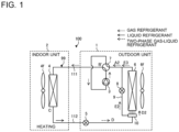
- Fig. 1 is a refrigerant circuit diagram illustrating a configuration of a refrigeration cycle apparatus 100 including a heat exchanger 6 according to Embodiment 1.
- the refrigeration cycle apparatus 100 including a refrigerant distributor 10 will be described with reference to Fig. 1 .
- arrows indicate the flows of refrigerant in a refrigerant circuit 99 of the refrigeration cycle apparatus 100 during a heating operation.
- Solid arrows indicate the flow of liquid refrigerant; dotted arrows indicate the flow of gas refrigerant; and a dashed arrow indicates the flow of two-phase gas-liquid refrigerant.
- an air-conditioning apparatus will be described.
- the refrigeration cycle apparatus 100 is used in refrigeration or air conditioning in, for example, a refrigerator, a freezer, a vending machine, an air-conditioning apparatus, a refrigeration apparatus, or a hot-water supply apparatus.
- the refrigeration cycle apparatus 100 includes the refrigerant circuit 99, in which a compressor 3, a flow switching device 7, an indoor heat exchanger 4, a pressure reducing device 5, and an outdoor heat exchanger 6 are sequentially connected by refrigerant pipes.
- the refrigeration cycle apparatus 100 includes an outdoor unit 1 and an indoor unit 2.
- the outdoor unit 1 includes the compressor 3, the flow switching device 7, the outdoor heat exchanger 6, the refrigerant distributor 10, and the pressure reducing device 5.
- the outdoor unit 1 accommodates an outdoor fan 6f that is provided close to the outdoor heat exchanger 6 to supply outdoor air.
- the indoor unit 2 accommodates the indoor heat exchanger 4 and an indoor fan 4f that supplies air to the indoor heat exchanger 4.
- the outdoor unit 1 and the indoor unit 2 are connected by two extension pipes 111 and 112 that are part of the refrigerant pipes.
- the outdoor fan 6f and the indoor fan 4f may each be generically referred to as a fan.
- a unit including a heat exchanger therein, such as the outdoor unit 1 or the indoor unit 2 may be referred to as a heat exchanger unit.
- the compressor 3 is a fluid machine that compresses and discharges sucked refrigerant.
- the flow switching device 7 is, for example, a four-way valve and is a device that switches a refrigerant passage for refrigerant between a refrigerant passage for a cooling operation and that for the heating operation under control by a controller (not illustrated).
- the indoor heat exchanger 4 is a heat exchanger that causes heat exchange to be performed between refrigerant flowing therein and indoor air supplied by the indoor fan 4f.
- the indoor heat exchanger 4 operates as a condenser in the heating operation and operates as an evaporator in the cooling operation.
- the pressure reducing device 5 is, for example, an expansion valve and is a device that decompresses refrigerant.
- the outdoor heat exchanger 6 is a heat exchanger that causes heat exchange to be performed between refrigerant flowing therein and air supplied by the outdoor fan 6f.
- the outdoor heat exchanger 6 operates as an evaporator in the heating operation and operates as a condenser in the cooling operation.
- the refrigerant circuit 99 of the refrigeration cycle apparatus 100 according to Embodiment 1 includes a bypass passage 9 that extends from the refrigerant distributor 10 of the outdoor heat exchanger 6 and bypasses a plurality of heat transfer tubes 30 (see Fig. 2 ).
- a flow control valve 8 is provided in the bypass passage 9. The opening degree of the flow control valve 8 is adjusted by the controller.
- Fig. 2 is an exploded perspective view illustrating a configuration of the heat exchanger 6 according to Embodiment 1.
- Fig. 3 is a diagram of a sectional configuration of the refrigerant distributor 10 of the heat exchanger 6 according to Embodiment 1.
- the outdoor heat exchanger 6 in the heating operation of the refrigeration cycle apparatus 100 will be described.
- the outdoor heat exchanger 6 may be simply referred to as the heat exchanger 6.
- Fig. 2 indicates an x axis, a y axis, and a z axis that are orthogonal to each other and that correspond to those in each of the figures.
- the heat exchanger 6 includes the heat transfer tubes 30 and the refrigerant distributor 10, which is connected to one end portion of each of the heat transfer tubes 30.
- the heat transfer tubes 30 are arranged in the z direction such that the tube axes thereof are parallel to each other.
- the heat transfer tubes 30 are disposed such that the tube axes extend in the x direction.
- the refrigerant distributor 10 is connected to the end portion of each of the heat transfer tubes 30 in the x direction. As indicated by arrows AF in Fig. 3 , air flows from the fan 6f in the y direction and passes through the spaces between the heat transfer tubes 30.
- the z direction may be referred to as a first direction
- the x direction may be referred to as a second direction
- the y direction may be referred to as a third direction.
- the z direction is in the opposite direction to the direction of gravity.
- the z direction is not limited to the direction parallel to the direction of gravity.
- the z direction may be inclined relative to the direction of gravity. It suffices that the z direction be at least set such that an imaginary line along the Z direction extends from a lower side toward an upper side.
- the inside of the refrigerant distributor 10 is partitioned into two spaces.
- the refrigerant distributor 10 has a cylindrical portion 60 whose inside is partitioned by a partition plate 11 into two spaces arranged in the x direction.
- a space located closer to the heat transfer tubes 30 will be referred to as a distribution chamber 21, and a space located farther from the heat transfer tubes 30 will be referred to as a gas-liquid separation chamber 20.
- a space located closer to the heat transfer tubes 30 will be referred to as a distribution chamber 21, and a space located farther from the heat transfer tubes 30 will be referred to as a gas-liquid separation chamber 20.
- a refrigerant inflow pipe 14 is connected to the gas-liquid separation chamber 20, a refrigerant inflow pipe 14 is connected. In the heating operation, two-phase gas-liquid refrigerant flows from the outside of the heat exchanger 6 into the gas-liquid separation chamber 20 through the refrigerant inflow pipe 14.
- the cylindrical portion 60 is a combination of outer shell components 12 and 13.
- the outer shell components 12 and 13 are made of plate materials. That is, the plate materials are bent into a semicylindrical shape, thereby forming the outer shell components 12 and 13.
- the outer shell component 12 is located farther from the heat transfer tubes 30, and has a gas passage hole 15 which is formed in an end portion of the outer shell component 12 in the z direction, and with which a gas passage pipe 15a is connected.
- the refrigerant inflow pipe 14 is connected to a central portion of the outer shell component 12 in the z direction.
- the outer shell component 13 is located closer to the heat transfer tubes 30, and has a plurality of slits into which the end portion 31 of each of the heat transfer tubes 30 is inserted. Both end portions of the cylindrical portion 60 in the z direction are closed by end-portion components 25 and 26 each of which is a plate-like component having a semicircular shape.
- the shape of the refrigerant distributor 10 is a cylindrical shape as illustrated in Figs. 2 and 3 , but is not limited to this shape.
- the refrigerant distributor 10 may be formed in the shape of a rectangular box.
- the partition plate 11 has a liquid passage hole 16 at an end portion of the partition plate 11 on the opposite side of a side, in the z direction, where the gas passage hole is provided.
- the liquid passage hole 16 causes a lower region of the gas-liquid separation chamber 20 and a lower region of the distribution chamber 21 to communicate with each other.
- the gas passage hole 15 is provided in upper part of the gas-liquid separation chamber 20.
- the gas passage pipe 15a which leads to the outside of the heat exchanger 6, is connected with the gas passage hole 15.
- the gas passage pipe 15a is also connected with the bypass passage 9 as illustrated in Fig. 1 .
- Fig. 4 is a sectional view illustrating a section of the gas-liquid separation chamber 20 that is taken along line A-A in Fig. 3 . Circles as illustrated in Fig. 4 schematically indicate respective positions of the refrigerant inflow pipe 14, the gas passage hole 15, and the liquid passage hole 16, which are connected to the gas-liquid separation chamber 20. In the heating operation, two-phase gas-liquid refrigerant flows from the refrigerant inflow pipe 14 into the gas-liquid separation chamber 20.
- liquid refrigerant 92 has a high density, and collects unevenly, that is, collects in the lower region of the gas-liquid separation chamber 20 because of the effect of gravity; and gas refrigerant 91 has a low density, and moves to an upper region of the gas-liquid separation chamber 20.
- gas refrigerant 91 accumulates in the upper region, and the liquid refrigerant 92 accumulates in the lower region, whereby the two-phase gas-liquid refrigerant is separated into the gas refrigerant 91 and the liquid refrigerant 92.
- the gas refrigerant 91 flows into the bypass passage 9 of the refrigerant circuit 99 via the gas passage hole 15 and the gas passage pipe 15a.
- the gas refrigerant 91 which is part of the two-phase gas-liquid refrigerant that has flowed into the refrigerant distributor 10, flows in the bypass passage 9.
- the liquid passage hole 16 which communicates with the distribution chamber 21
- the liquid refrigerant 92 flows into the distribution chamber 21 via the liquid passage hole 16.
- the liquid refrigerant 92 flows into the distribution chamber 21.
- the two-phase gas-liquid refrigerant can flow in the distribution chamber 21.
- Embodiment 1 Only the liquid refrigerant 92 flows into the distribution chamber 21. Thus, in Embodiment 1, only the liquid refrigerant 92 flows in the heat transfer tubes 30. Therefore, where the heat transfer tubes 30 are classified into heat transfer tubes 30 located on an upper side and heat transfer tubes 30 located on a lower side in the direction of gravity, the liquid refrigerant 92 flows equally in the heat transfer tubes 30 located on the upper side and the heat transfer tubes 30 located on the lower side. Thus, when the heat exchanger 6 operates as an evaporator, gas refrigerant, which does not contribute to evaporation of refrigerant, does not flow in the heat transfer tubes 30.
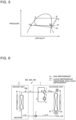
- Fig. 5 is a Mollier diagram of the refrigeration cycle apparatus 100 according to Embodiment 1.
- a solid line indicates a refrigeration cycle apparatus of a comparative example in the case where two-phase gas-liquid refrigerant directly passes through an evaporator; and a dash line is a Mollier diagram for refrigerant that circulates in the refrigeration cycle apparatus 100 according to Embodiment 1.
- the two-phase gas-liquid refrigerant that has been decompressed by the pressure reducing device 5 to be in a state indicated by a point D in Figs. 1 and 5 flows into the heat exchanger 6 and is separated in the gas-liquid separation chamber 20.
- the liquid refrigerant 92 that has been separated in the gas-liquid separation chamber 20 and has flowed into the distribution chamber 21 is in a state indicated by a point D2. Then, the liquid refrigerant 92 flows into the heat transfer tubes 30 and is evaporated to be in a state indicated by a point A2.
- the state of the refrigerant is changed from the state indicated by the point D to a state indicated by a point A.
- two-phase gas-liquid refrigerant passes through the heat transfer tubes 30 to change into gas refrigerant, and its pressure lowers because of a pressure loss that occurs when the refrigerant passes through the heat transfer tubes 30.
- refrigerant passing through the heat transfer tubes 30 is the liquid refrigerant 92 indicated by the point D2 in Fig. 5 .
- the gas refrigerant 91 passes through the bypass passage 9 and joins gas refrigerant that has passed through the heat exchanger 6 operating as an evaporator. That is, the gas refrigerant 91 that has passed through the bypass passage 9 and that is in a state indicated by a point E2 in Fig.
- a refrigeration cycle apparatus 200 according to Embodiment 2 the bypass passage 9 is removed from the refrigerant circuit 99 of the refrigeration cycle apparatus 100 according to Embodiment 1 and the configuration of the heat exchanger 6 is changed.
- the refrigeration cycle apparatus 200 according to Embodiment 2 will be described by referring mainly to the differences between Embodiments 1 and 2.
- components that have the same functions as those in Embodiment 1 are denoted by the same reference signs.
- Fig. 6 is a refrigerant circuit diagram illustrating a configuration of the refrigeration cycle apparatus 200, which includes a heat exchanger 206 according to Embodiment 2.
- a refrigerant circuit 299 of the refrigeration cycle apparatus 200 according to Embodiment 2 does not include the bypass passage 9 which extends from the refrigerant distributor 10 of the outdoor heat exchanger 6 of the outdoor unit 1 to the flow switching device 7 and which bypasses the heat transfer tubes 30.
- the refrigerant circuit 299 is different from the refrigerant circuit 99 according to Embodiment 1.
- Fig. 7 is an exploded perspective view illustrating a configuration of the heat exchanger 206 according to Embodiment 2.
- Fig. 8 is a diagram illustrating a sectional configuration of a refrigerant distributor 210 of the heat exchanger 206 according to Embodiment 2.
- the heat exchanger 206 according to Embodiment 2 does not include a gas passage hole 15 and a gas passage pipe 15a that extend from the gas-liquid separation chamber 20 of the refrigerant distributor 210 toward the outside of the heat exchanger 206. Instead, in upper part of the gas-liquid separation chamber 20 in the z direction, a gas passage hole 215 is provided to communicate with the distribution chamber 21. In addition, in lower part of the gas-liquid separation chamber 20 in the z direction, the liquid passage hole 16 is provided to communicate with the distribution chamber 21 as in Embodiment 1.
- the distribution chamber 21 is partitioned by a division plate 217 into two spaces arranged in the y direction. That is, the distribution chamber 21 includes a first distribution chamber 221 located on the windward side and a second distribution chamber 222 located on the leeward side. It should be noted that referring to Fig. 8 , the fan 6f is configured to send air in the y direction.
- the first distribution chamber 221 and the second distribution chamber 222 are partitioned off by the division plate 217, which has a comb-like shape to coincide with the arrangement of the heat transfer tubes 30.
- the first distribution chamber 221 communicates with the gas-liquid separation chamber 20 via the liquid passage hole 16.
- the liquid passage hole 16 is formed in the lower part of the gas-liquid separation chamber 20 in the direction of gravity.
- the liquid refrigerant 92 that accumulates in the lower region of the gas-liquid separation chamber 20 flows into the first distribution chamber 221.
- the second distribution chamber 222 communicates with the gas-liquid separation chamber 20 via the gas passage hole 215.
- the gas passage hole 215 is formed in the upper part of the gas-liquid separation chamber 20 in the direction of gravity.
- the gas refrigerant 91 that accumulates in the upper region of the gas-liquid separation chamber 20 flows into the second distribution chamber 222.
- Fig. 9 is a sectional view of the gas-liquid separation chamber 20.
- the section illustrated in Fig. 9 is perpendicular to the x axis and is taken along line A-A in Fig. 8 .
- the two-phase gas-liquid refrigerant that has flowed from the refrigerant inflow pipe 14 into the gas-liquid separation chamber 20 is separated due to the effect of gravity, as in Embodiment 1.
- the gas passage hole 215 is provided in the upper part of the gas-liquid separation chamber 20.
- the gas refrigerant 91 flows into the second distribution chamber 222 of the distribution chamber 21 through the gas passage hole 215. Therefore, only the gas refrigerant 91 exists in the second distribution chamber 222.
- the liquid passage hole 16 which communicates with the distribution chamber 21, is provided in the lower part of the gas-liquid separation chamber 20.
- the liquid refrigerant 92 flows into the first distribution chamber 221 of the distribution chamber 21 via the liquid passage hole 16. Therefore, only the liquid refrigerant 92 exists in the first distribution chamber 221.
- the liquid passage hole 16 and the gas passage hole 215 are each designed to have an appropriate size depending on an estimated flow rate of refrigerant.
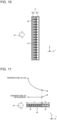
- Fig. 10 is a sectional view of the distribution chamber 21.
- the section as illustrated in Fig. 10 is perpendicular to the x axis and taken along line B-B in Fig. 8 .
- the heat transfer tubes 30 are inserted in both the first distribution chamber 221 and the second distribution chamber 222 of the distribution chamber 21.
- At an end face 33 (see Fig. 11 ) some of refrigerant passage portions 32 (see Fig. 11 ) in each of the heat transfer tubes 30 communicate with the first distribution chamber 221, and others of the refrigerant passage portions 32 communicate with the second distribution chamber 222.
- Fig. 11 is a diagram illustrating a temperature distribution and regions of each of the heat transfer tubes 30 as illustrated in Fig. 10 , in which liquid refrigerant and gas refrigerant flow.
- liquid refrigerant flows in refrigerant passage portions 32 located in a region L of the heat transfer tube 30 that is located on the windward side thereof; and gas refrigerant flows in refrigerant passage portions 32 located in a region G of the heat transfer tube 30 that is located on the leeward side thereof.
- the region L into which liquid refrigerant flows be made larger than the region G into which gas refrigerant flows.
- the temperature of the liquid refrigerant in the region L on the windward side is substantially constant.
- the temperature of the air is reduced by the latent heat of the liquid refrigerant.
- the liquid refrigerant that passes through the region L is evaporated by sensible heat from the air to change into gas refrigerant.
- the greater the distance between the position of the gas refrigerant that flows in the region L and the position of the region L in which liquid refrigerant flows the higher the temperature of the gas refrigerant.
- liquid refrigerant flows in the region L of the heat transfer tube 30, which is located on the windward side thereof, whereby it is possible to easily ensure a sufficient difference in temperature between air and the refrigerant, thus improving the heat transfer performance of the heat exchanger 206.
- the heat exchanger 206 separates two-phase gas-liquid refrigerant into liquid refrigerant in the first distribution chamber 221 and gas refrigerant in the second distribution chamber 222, and then causes the liquid refrigerant and the gas refrigerant to flow in the different regions of the heat transfer tube 30. It is therefore possible to reduce variation between the ratios between the gas refrigerant and the liquid refrigerant of refrigerant that flows in the heat transfer tubes 30. Thus, the heat exchanger 206 is capable of achieving a desired heat exchange performance.
- a refrigeration cycle apparatus 300 according to Embodiment 3 the first distribution chamber 221 and the second distribution chamber 222 of the heat exchanger 206 according to Embodiment 2 are interchanged in position.
- the refrigeration cycle apparatus 300 according to Embodiment 3 will be described by referring mainly to the differences between Embodiments 2 and 3.
- components that have the same functions as those in those in Embodiment 1 and/or Embodiment 2 are denoted by the same reference signs.
- Fig. 12 is a diagram of a sectional configuration of a refrigerant distributor 310 of a heat exchanger 306 according to Embodiment 3.
- the first distribution chamber 221 and the second distribution chamber 222 are interchanged in position in the y direction. That is, in the heat exchanger 306, the second distribution chamber 222 is located on the windward side, and the first distribution chamber 221 is located on the leeward side.
- Fig. 13 is a diagram illustrating a temperature distribution and regions of each of the heat transfer tubes 30 in Fig. 12 , in which liquid refrigerant and gas refrigerant flow.
- the region G in which gas refrigerant flows is located on the windward side of the heat transfer tubes 30, and the region L in which liquid refrigerant flows is located on the leeward side of the heat transfer tube 30.
- the heat exchanger 306 can achieve a desired heat exchange performance.
- the heat exchanger 306 can achieve a desired heat exchange performance.
- a refrigeration cycle apparatus 400 according to Embodiment 4 is different from that according to Embodiment 2 in configuration of the heat exchanger; that is, the configuration of the heat exchanger according to Embodiment 4 is different from that of the heat exchanger 206 according to Embodiment 2.
- the refrigeration cycle apparatus 400 according to Embodiment 4 will be described by referring mainly to the differences between Embodiments 2 and 4.
- components that have the same functions as those in any of Embodiments 1 to 3 are denoted by the same reference signs.
- Fig. 14 is an exploded perspective view illustrating a configuration of a heat exchanger 406 according to Embodiment 4.
- Fig. 15 is a diagram of a sectional configuration of a refrigerant distributor 410 of the heat exchanger 406 according to Embodiment 4, two-phase gas-liquid refrigerant that has flowed from the refrigerant inflow pipe 14 into the gas-liquid separation chamber 20 is separated into gas refrigerant and liquid refrigerant in the gas-liquid separation chamber 20.
- the heat exchanger 406 according to Embodiment 4 is the same as the heat exchangers 6, 206, and 306 in Embodiments 1 to 3.
- a distribution chamber 421 connected to the heat transfer tubes 30 is partitioned by partition components 42 into a plurality of spaces arranged in the z direction.
- the refrigerant distributor 410 includes, between the gas-liquid separation chamber 20 and the distribution chamber 421, a liquid chamber 427 into which only liquid refrigerant flows and a gas chamber 428 into which only gas refrigerant flows.
- a gas passage hole 415a is provided in upper part of the gas-liquid separation chamber 20, that is, upper part of a partition plate 411, and a liquid passage hole 416a is provided in lower part of the gas-liquid separation chamber 20, that is, lower part of the partition plate 411.
- the gas chamber 428 communicates with the gas-liquid separation chamber 20 through the gas passage hole 415a.
- the liquid chamber 427 communicates with the gas-liquid separation chamber 20 through the liquid passage hole 416a.
- only liquid refrigerant flows into the liquid chamber 427.
- the liquid chamber 427 and the gas chamber 428 are partitioned off by a division plate 417 and are independent spaces.
- the distribution chamber 421 and each of the liquid chamber 427 and the gas chamber 428 are partitioned off by a partition plate 418.
- the liquid chamber 427 has liquid passage holes 416b that are provided in the partition plate 418 and that communicate with the distribution chamber 421.
- the gas chamber 428 has gas passage holes 415b that are provided in the partition plate 418 and that communicate with the distribution chamber 421.
- the distribution chamber 421, in which the heat transfer tubes 30 are inserted is partitioned into a plurality of joining regions 421a, 421b, 421c, and 421d arranged in the z direction. For each of the joining regions 421a, 421b, 421c, and 421d, an associated one of the liquid passage holes 416b and an associated one of the gas passage holes 415b are provided.
- liquid refrigerant in the liquid chamber 427 and gas refrigerant in the gas chamber 428 evenly flow into the joining regions 421a, 421b, 421c, and 421d.
- the gas refrigerant and the liquid refrigerant that have flowed into each of the joining regions 421a, 421b, 421c, and 421d are mixed, and refrigerant resulting from this mixture flows into the heat transfer tubes 30.
- gas refrigerant and liquid refrigerant, which are separated from each other, flow into each of the joining regions 421a, 421b, 421c, and 421d through different paths.
- the heat transfer tubes 30 are flat multi-hole tubes, when gas refrigerant and liquid refrigerant flow separately in refrigerant passages, a temperature difference is made between the gas refrigerant and the liquid refrigerant.
- the gas refrigerant and the liquid refrigerant exchange heat with each other, as a result of which the amount of heat exchange between air and refrigerant that passes through a heat exchanger may be lowered.
- Embodiment 4 when gas refrigerant and liquid refrigerant flow into the joining regions 421a, 421b, 421c, and 421d and then join each other therein, the ratios between the gas refrigerant and the liquid refrigerant that flow into the joining regions 421a, 421b, 421c, and 421d are substantially the same as each other. It is therefore possible to cause a mixture of the gas refrigerant and the liquid refrigerant to flow in each of the heat transfer tubes 30, thus reducing heat exchange between gas refrigerant and liquid refrigerant and promoting heat exchange between air and refrigerant.
- the heat exchanger 406 separates two-phase gas-liquid refrigerant into gas refrigerant and liquid refrigerant and thereafter causes the gas refrigerant and the liquid refrigerant to join each other in the joining regions 421a, 421b, 421c, and 421d, which are partitioned off.
- the heat exchanger 406 it is possible to reduce variation between the ratios between the gas refrigerant and the liquid refrigerant that flow into the joining regions 421a, 421b, 421c, and 421d, and also reduces variation between the ratios between the gas refrigerant and the liquid refrigerant flow in the heat transfer tubes 30.
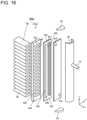
- Fig. 16 is an exploded perspective view illustrating a configuration of a heat exchanger 406a that is a modification of the heat exchanger 406 according to Embodiment 4.
- the refrigerant distributor 410 is partitioned, by the two partition plates 411 and 418, into three spaces arranged in the x direction. The spaces are used as spaces in which refrigerant is separated or joins.
- plate materials 451 and 454 are stacked, and holes or elongate holes such as a gas passage hole 415 and a liquid passage hole 416 are provided in the plate materials, thereby providing spaces in which refrigerant is separated or joins.
- two elongate holes 452 whose major axes extend in the z direction, are provided in the plate material 451 such that the elongate holes 452 are arranged in the y direction, thereby providing a liquid chamber 427 and a gas chamber 428.
- One of the two elongate holes 452 communicates with the gas-liquid separation chamber 20 through the gas passage hole 415.
- the other of the two elongate holes 452 communicates with the gas-liquid separation chamber 20 through the liquid passage hole 416.
- Each of the elongate holes 455 is formed in association with an associated one of the heat transfer tubes 30.
- Each of the elongate holes 455 communicates with both the elongate hole 452 serving as the liquid chamber 427 and the elongate hole 452 serving as the gas chamber 428.
- each of the elongate holes 455 is formed in association with an associated one of the heat transfer tubes 30, but it is not limiting.
- each of the distribution chambers 421 may be connected to associated two or more of the heat transfer tubes 30.
- a refrigerant distributor 410a of the heat exchanger 406a of the modification example is formed by the following simple way: holes are formed in components such as the plate materials 451 and 454, and the components are then stacked together.
- the heat exchanger 406a can be manufactured with a small number of components at a low cost.
- the thickness of the refrigerant distributor 410a in the x direction is reduced. Accordingly, it is possible to increase the area for a heat transfer section in which the heat transfer tubes 30 are provided.
- a refrigeration cycle apparatus 500 according to Embodiment 5 is different from that according to Embodiment 2 in configuration of the heat exchanger; that is, the configuration of the heat exchanger according to Embodiment 5 is different from that of the heat exchanger 206 according to Embodiment 2.
- the refrigeration cycle apparatus 500 according to Embodiment 5 will be described by referring mainly to the differences between Embodiments 2 and 5.
- components that have the same function as those in any of Embodiments 1 to 4 are denoted by the same reference signs.
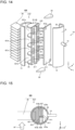
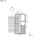
- Fig. 17 is a diagram of a sectional configuration of a heat exchanger 506 according to Embodiment 5.
- Fig. 17 illustrates a section along the x and z axes.
- a refrigerant distributor 510 of the heat exchanger 506 according to Embodiment 5 includes a liquid refrigerant catch structure 570 in the gas-liquid separation chamber 20.
- the liquid refrigerant catch structure 570 is a mesh filter whose mesh size and material can be set as appropriate.
- the liquid refrigerant catch structure 570 is located between a refrigerant inflow pipe 514 and the gas passage hole 15 in the z direction, and is provided in such a manner as to partition the gas-liquid separation chamber 20 into spaces arranged in the z direction.
- the refrigerant inflow pipe 514 is inserted in the gas-liquid separation chamber 20 such that the refrigerant inflow pipe 514 is inclined in the opposite direction to the z direction.
- two-phase gas-liquid refrigerant that has flowed from the refrigerant inflow pipe 514 into the gas-liquid separation chamber 20 moves in the opposite direction to the z direction.
- the two-phase gas-liquid refrigerant is unevenly present in the gas-liquid separation chamber 20 such that liquid refrigerant accumulates in the lower region of the gas-liquid separation chamber 20 because of the effect of gravity, and gas refrigerant and liquid refrigerant that is in the form of fine particles are present in the upper region of the gas-liquid separation chamber 20.
- the gas passage hole 15 is set in the upper part of the gas-liquid separation chamber 20, and the separated gas refrigerant thus flows into the second distribution chamber 222 of the distribution chamber 21 via the gas passage hole 15.
- the liquid refrigerant that floats in the form of fine particles may flow into the second distribution chamber 222.
- the refrigerant distributor 510 of the heat exchanger 506 according to Embodiment 5, as well as the refrigerant distributor 210 of the heat exchanger 206 according to Embodiment 2 includes the distribution chamber 21 which includes the first distribution chamber 221 and the second distribution chamber 222.
- the liquid refrigerant catch structure 570 is a structure that allows gas refrigerant to pass therethrough. Because of provision of the liquid refrigerant catch structure 570, the heat exchanger 506 can obtain the following advantage: liquid refrigerant which moves together with gas refrigerant, toward the upper region of the gas-liquid separation chamber 20 adheres to the liquid refrigerant catch structure 570, becomes liquid droplets, and drips down in the direction of gravity. Thus, in the heat exchanger 506 according to Embodiment 5, separation of gas refrigerant and liquid refrigerant is promoted.
- a refrigeration cycle apparatus 600 according to Embodiment 6 is different from that according to Embodiment 2 in configuration of the heat exchanger; that is, the configuration of the heat exchanger according to Embodiment 5 is different from that of the heat exchanger 206 according to Embodiment 2.
- the refrigeration cycle apparatus 600 according to Embodiment 6 will be described by referring mainly to the differences between Embodiments 2 and 6.
- components of the refrigeration cycle apparatus 600 according to Embodiment 6 in each of related figures, components that have the same functions as those in any of Embodiments 1 to 5 are denoted by the same reference signs.
- Fig. 18 is a diagram of a sectional configuration of a heat exchanger 606 according to Embodiment 6.
- Fig. 18 illustrates a section along the x and z axes.
- a refrigerant distributor 610 of the heat exchanger 606 according to Embodiment 6 includes a baffle plate 670 in the gas-liquid separation chamber 20.
- the baffle plate 670 is provided below a location where a refrigerant inflow pipe 614 is inserted.
- the baffle plate 670 extends from a wall surface in which the refrigerant inflow pipe 614 is set, toward the partition plate 11.
- the baffle plate 670 has a communication hole 671 that is close to the partition plate 11 and that causes the upper region and the lower region of the gas-liquid separation chamber 20 to communicate with each other.
- the baffle plate 670 is inclined in the opposite direction to the z direction toward the partition plate 11.
- the baffle plate 670 is formed to cause two-phase gas-liquid refrigerant flowing from the refrigerant inflow pipe 614, which is also inclined in the opposite direction to the z direction, to flow along the baffle plate 670.
- the baffle plate 670 and the refrigerant inflow pipe 614 are provided parallel to each other, but their configuration is not limited to this configuration.
- the refrigerant inflow pipe 614 may be more greatly inclined in the opposite direction to the z direction than the baffle plate 670 such that two-phase gas-liquid refrigerant that has flowed from the refrigerant inflow pipe 614 comes into contact with the baffle plate 670.
- two-phase gas-liquid refrigerant comes into contact with the baffle plate 670
- liquid refrigerant contained in the two-phase gas-liquid refrigerant adheres to a surface of the baffle plate 670 and flows down through the communication hole 671. Therefore, in the gas-liquid separation chamber 20, separation of gas refrigerant and liquid refrigerant in the gas-liquid separation chamber 20 is promoted.
- the gas-liquid separation chamber 20 is partitioned by the baffle plate 670, into two spaces arranged in the z direction.
- a lower space and an upper space relative to the baffle plate 670 will be referred to as a first space 620a and a second space 620b, respectively.
- a gas passage pipe 615a is connected to a gas passage hole 615 provided in the second space 620b, which is the upper space in the gas-liquid separation chamber 20.
- An end portion 615b of the gas passage pipe 615a is located in the second space 620b, which is the lower space relative to the baffle plate 670.
- the gas passage pipe 615a is configured to enable gas refrigerant to be sent from upper part of the lower space relative to the baffle plate 670 to the second distribution chamber 222.
- liquid refrigerant adheres to the baffle plate 670 and the partition plate 11 and flows down. Therefore, gas refrigerant flows into the gas passage pipe 615a. As a result, the gas refrigerant and the liquid refrigerant are efficiently separated in the gas-liquid separation chamber 20.
- each of the heat exchangers 6, 206, 306, 406, 506, and 606 plate materials may be stacked as in the heat exchanger 406a.
- the heat exchangers 6, 206, 306, 406, 506, and 606 are applied to the outdoor unit 1, they may be applied not only to the outdoor unit 1, but also to the indoor unit 2.
- the embodiments may be combined.
- the liquid refrigerant catch structure 570 in Embodiment 5 may be applied to Embodiment 1, 3, 4, or 6.
- the configuration of the baffle plate 670 in Embodiment 6 may be applied to Embodiment 1, 3, 4, or 5.
Landscapes
- Engineering & Computer Science (AREA)
- Physics & Mathematics (AREA)
- Thermal Sciences (AREA)
- Mechanical Engineering (AREA)
- General Engineering & Computer Science (AREA)
- Heat-Exchange Devices With Radiators And Conduit Assemblies (AREA)
- Details Of Heat-Exchange And Heat-Transfer (AREA)
Abstract
Description
- The present disclosure relates to a heat exchanger, a heat exchanger unit, and a refrigeration cycle apparatus, and in particular, to a structure for distributing refrigerant to a plurality of heat transfer tubes.
- As an existing heat exchanger, a heat exchanger is known which includes a plurality of heat transfer tubes disposed apart from each other in the direction of gravity and a header connected to an end portion of each of the heat transfer tubes, and which causes heat exchange to be performed between air and refrigerant that flows in the heat transfer tubes. The heat exchanger is provided in a refrigeration cycle apparatus such as an air-conditioning apparatus, and included in a refrigeration cycle circuit. In air-conditioning apparatuses, in order to reduce the amount of refrigerant in a refrigerant circuit and to improve a heat exchanger performance, heat transfer tubes in a heat exchanger have been made smaller. In order that heat transfer tubes be made smaller, it is necessary to reduce an increase in pressure loss of refrigerant that passes through the heat transfer tubes. Thus, the number of paths (branches) in a heat exchanger is increased. Accordingly, in the heat exchanger, refrigerant branches a larger number of times. Thus, when the heat operates as an evaporator, a refrigerant distributor (header) of the heat exchanger is required to equally distribute two-phase gas-liquid refrigerant that flows thereinto to the plurality of heat transfer tubes.
- For example, there is proposed a heat exchanger in which refrigerant that flows into a header is circulated in the header, whereby even when the refrigerant is two-phase gas-liquid refrigerant, the amounts of liquid refrigerant and gas refrigerant that flows into heat transfer tubes arranged in the direction of gravity, that is, an up-down direction, are equalized (see, for example, Patent Literature 1).
- Patent Literature 1:
Japanese Patent No. 6369650 - However, in the heat exchanger disclosed in Patent Literature 1, liquid refrigerant may not be raised to the uppermost part of the header due to the effect of gravity under the condition that the flow velocity of refrigerant is low, for example, in a low-load operation of a refrigeration cycle apparatus. In this case, the heat exchanger has a problem in which a large amount of liquid refrigerant flows into heat transfer tubes located under the header, thus deteriorating the heat exchange performance.
- The present disclosure is applied to solve the above problem, and relates to a heat exchanger, a heat exchanger unit, and a refrigeration cycle apparatus that are capable of reducing an imbalance between the amounts of liquid refrigerant and gas refrigerant that flow in a plurality of heat transfer tubes even in a low-load operation of the refrigeration cycle apparatus.
- A heat exchanger according to an embodiment of the present disclosure includes: a plurality of heat transfer tubes arranged in a first direction and extending in a second direction perpendicular to the first direction; a refrigerant distributor connected to one end portion of each of the plurality of heat transfer tubes; and a refrigerant inflow pipe connected to the refrigerant distributor. The refrigerant distributor is formed to extend in the first direction, and includes: a gas-liquid separation chamber in which refrigerant that flows from the refrigerant inflow pipe into the gas-liquid separation chamber is separated into gas refrigerant and liquid refrigerant; a distribution chamber connected to the end portion of each of the plurality of heat transfer tubes; a liquid passage hole through which the liquid refrigerant flows, and through which the gas-liquid separation chamber and the distribution chamber communicate with each other; and a gas passage hole through which the gas refrigerant flows, and which is provided offset from the liquid passage hole in the first direction.
- A heat exchanger unit according to another embodiment of the present disclosure includes the heat exchanger and a fan that sends air to the heat exchanger.
- A refrigeration cycle apparatus according to still another embodiment of the present disclosure includes the heat exchanger unit.
- According to the embodiments of the present disclosure, by virtue of the above configurations, it is possible to separate two-phase gas-liquid refrigerant that flows into the heat exchanger, into gas refrigerant and liquid refrigerant, and then distribute the gas refrigerant and the liquid refrigerant to the plurality of heat transfer tubes. Thus, it is possible to reduce variation between the ratios between gas refrigerant and liquid refrigerant that flow in the heat transfer tubes, even under the condition in which the flow velocity of refrigerant is low.
-
- [
Fig. 1] Fig. 1 is a refrigerant circuit diagram illustrating a configuration of arefrigeration cycle apparatus 100 including aheat exchanger 6 according to Embodiment 1. - [
Fig. 2] Fig. 2 is an exploded perspective view illustrating a configuration of theheat exchanger 6 according to Embodiment 1. - [
Fig. 3] Fig. 3 is a diagram of a sectional configuration of arefrigerant distributor 10 of theheat exchanger 6 according to Embodiment 1. - [
Fig. 4] Fig. 4 is a sectional view of a gas-liquid separation chamber 20. - [
Fig. 5] Fig. 5 is a Mollier diagram of therefrigeration cycle apparatus 100 according to Embodiment 1. - [
Fig. 6] Fig. 6 is a refrigerant circuit diagram illustrating a configuration of a refrigeration cycle apparatus 200 including aheat exchanger 206 according toEmbodiment 2. - [
Fig. 7] Fig. 7 is an exploded perspective view illustrating a configuration of theheat exchanger 206 according toEmbodiment 2. - [
Fig. 8] Fig. 8 is a diagram of a sectional configuration of arefrigerant distributor 210 of theheat exchanger 206 according toEmbodiment 2. - [
Fig. 9] Fig. 9 is a sectional view of a gas-liquid separation chamber 20. - [
Fig. 10] Fig. 10 is a sectional view of adistribution chamber 21. - [
Fig. 11] Fig. 11 is a diagram illustrating a temperature distribution and regions of each of a plurality ofheat transfer tubes 30 as illustrated inFig. 10 , in which liquid refrigerant and gas refrigerant flow. - [
Fig. 12] Fig. 12 is a diagram of a sectional configuration of a refrigerant distributor 310 of aheat exchanger 306 according toEmbodiment 3. - [
Fig. 13] Fig. 13 is a diagram illustrating a temperature distribution and regions of each of a plurality ofheat transfer tubes 30 as illustrated inFig. 12 , in which liquid refrigerant and gas refrigerant flow. - [
Fig. 14] Fig. 14 is an exploded perspective view illustrating a configuration of aheat exchanger 406 according toEmbodiment 4. - [
Fig. 15] Fig. 15 is a diagram of a sectional configuration of arefrigerant distributor 410 of theheat exchanger 406 according toEmbodiment 4. - [
Fig. 16] Fig. 16 is an exploded perspective view illustrating a configuration of aheat exchanger 406a, which is a modification of theheat exchanger 406 according toEmbodiment 4. - [
Fig. 17] Fig. 17 is a diagram of a sectional configuration of aheat exchanger 506 according to Embodiment 5. - [
Fig. 18] Fig. 18 is a diagram of a sectional configuration of aheat exchanger 606 according toEmbodiment 6. - Heat exchangers, heat exchanger units, and refrigeration cycle apparatuses according to embodiments will be described. The configurations as illustrated in the figures are examples, and their illustrations are not limiting. In each of the figures, components that are the same as or equivalent to those in a previous figures or previous figures are denoted by the same reference signs, and the same is true of the entire text of the specification. In order that the embodiments be more easily understood, terms related to directions (for example, "up", "down", "right", "left", "forward", and "backward") are used as appropriate. However, these terms are merely used as a matter of convenience for explanation and do not limit the locations or orientations of apparatuses or components. In addition, relationships in size between the components in the figures may differ from those of actual ones.
-
Fig. 1 is a refrigerant circuit diagram illustrating a configuration of arefrigeration cycle apparatus 100 including aheat exchanger 6 according to Embodiment 1. First of all, therefrigeration cycle apparatus 100 including arefrigerant distributor 10 will be described with reference toFig. 1 . InFig. 1 , arrows indicate the flows of refrigerant in arefrigerant circuit 99 of therefrigeration cycle apparatus 100 during a heating operation. Solid arrows indicate the flow of liquid refrigerant; dotted arrows indicate the flow of gas refrigerant; and a dashed arrow indicates the flow of two-phase gas-liquid refrigerant. Regarding Embodiment 1, as an example of therefrigeration cycle apparatus 100, an air-conditioning apparatus will be described. However, therefrigeration cycle apparatus 100 is used in refrigeration or air conditioning in, for example, a refrigerator, a freezer, a vending machine, an air-conditioning apparatus, a refrigeration apparatus, or a hot-water supply apparatus. - The
refrigeration cycle apparatus 100 includes therefrigerant circuit 99, in which acompressor 3, aflow switching device 7, anindoor heat exchanger 4, a pressure reducing device 5, and anoutdoor heat exchanger 6 are sequentially connected by refrigerant pipes. Therefrigeration cycle apparatus 100 includes an outdoor unit 1 and anindoor unit 2. The outdoor unit 1 includes thecompressor 3, theflow switching device 7, theoutdoor heat exchanger 6, therefrigerant distributor 10, and the pressure reducing device 5. The outdoor unit 1 accommodates anoutdoor fan 6f that is provided close to theoutdoor heat exchanger 6 to supply outdoor air. Theindoor unit 2 accommodates theindoor heat exchanger 4 and anindoor fan 4f that supplies air to theindoor heat exchanger 4. The outdoor unit 1 and theindoor unit 2 are connected by twoextension pipes 111 and 112 that are part of the refrigerant pipes. It should be noted that theoutdoor fan 6f and theindoor fan 4f may each be generically referred to as a fan. In addition, a unit including a heat exchanger therein, such as the outdoor unit 1 or theindoor unit 2, may be referred to as a heat exchanger unit. - The
compressor 3 is a fluid machine that compresses and discharges sucked refrigerant. Theflow switching device 7 is, for example, a four-way valve and is a device that switches a refrigerant passage for refrigerant between a refrigerant passage for a cooling operation and that for the heating operation under control by a controller (not illustrated). Theindoor heat exchanger 4 is a heat exchanger that causes heat exchange to be performed between refrigerant flowing therein and indoor air supplied by theindoor fan 4f. Theindoor heat exchanger 4 operates as a condenser in the heating operation and operates as an evaporator in the cooling operation. The pressure reducing device 5 is, for example, an expansion valve and is a device that decompresses refrigerant. An electronic expansion valve whose opening degree is adjusted under control by the controller can be used as the pressure reducing device 5. Theoutdoor heat exchanger 6 is a heat exchanger that causes heat exchange to be performed between refrigerant flowing therein and air supplied by theoutdoor fan 6f. Theoutdoor heat exchanger 6 operates as an evaporator in the heating operation and operates as a condenser in the cooling operation. - The
refrigerant circuit 99 of therefrigeration cycle apparatus 100 according to Embodiment 1 includes a bypass passage 9 that extends from therefrigerant distributor 10 of theoutdoor heat exchanger 6 and bypasses a plurality of heat transfer tubes 30 (seeFig. 2 ). In the bypass passage 9, a flow control valve 8 is provided. The opening degree of the flow control valve 8 is adjusted by the controller. -
Fig. 2 is an exploded perspective view illustrating a configuration of theheat exchanger 6 according to Embodiment 1.Fig. 3 is a diagram of a sectional configuration of therefrigerant distributor 10 of theheat exchanger 6 according to Embodiment 1. Regarding Embodiment 1, theoutdoor heat exchanger 6 in the heating operation of therefrigeration cycle apparatus 100 will be described. In the following description, theoutdoor heat exchanger 6 may be simply referred to as theheat exchanger 6.Fig. 2 indicates an x axis, a y axis, and a z axis that are orthogonal to each other and that correspond to those in each of the figures. - The
heat exchanger 6 includes theheat transfer tubes 30 and therefrigerant distributor 10, which is connected to one end portion of each of theheat transfer tubes 30. Theheat transfer tubes 30 are arranged in the z direction such that the tube axes thereof are parallel to each other. Theheat transfer tubes 30 are disposed such that the tube axes extend in the x direction. Therefrigerant distributor 10 is connected to the end portion of each of theheat transfer tubes 30 in the x direction. As indicated by arrows AF inFig. 3 , air flows from thefan 6f in the y direction and passes through the spaces between theheat transfer tubes 30. It should be noted that the z direction may be referred to as a first direction, the x direction may be referred to as a second direction, and the y direction may be referred to as a third direction. In Embodiment 1, the z direction is in the opposite direction to the direction of gravity. However, the z direction is not limited to the direction parallel to the direction of gravity. The z direction may be inclined relative to the direction of gravity. It suffices that the z direction be at least set such that an imaginary line along the Z direction extends from a lower side toward an upper side. - As illustrated in
Fig. 3 , in a section perpendicular to the z axis, the inside of therefrigerant distributor 10 is partitioned into two spaces. Therefrigerant distributor 10 has acylindrical portion 60 whose inside is partitioned by apartition plate 11 into two spaces arranged in the x direction. Of the two spaces, a space located closer to theheat transfer tubes 30 will be referred to as adistribution chamber 21, and a space located farther from theheat transfer tubes 30 will be referred to as a gas-liquid separation chamber 20. In thedistribution chamber 21, oneend portion 31 of each of theheat transfer tubes 30 is inserted. To the gas-liquid separation chamber 20, arefrigerant inflow pipe 14 is connected. In the heating operation, two-phase gas-liquid refrigerant flows from the outside of theheat exchanger 6 into the gas-liquid separation chamber 20 through therefrigerant inflow pipe 14. - The
cylindrical portion 60 is a combination ofouter shell components outer shell components outer shell components outer shell component 12 is located farther from theheat transfer tubes 30, and has agas passage hole 15 which is formed in an end portion of theouter shell component 12 in the z direction, and with which agas passage pipe 15a is connected. In addition, to a central portion of theouter shell component 12 in the z direction, therefrigerant inflow pipe 14 is connected. Of the outer shell components, theouter shell component 13 is located closer to theheat transfer tubes 30, and has a plurality of slits into which theend portion 31 of each of theheat transfer tubes 30 is inserted. Both end portions of thecylindrical portion 60 in the z direction are closed by end-portion components refrigerant distributor 10 is a cylindrical shape as illustrated inFigs. 2 and3 , but is not limited to this shape. For example, therefrigerant distributor 10 may be formed in the shape of a rectangular box. - The
partition plate 11 has aliquid passage hole 16 at an end portion of thepartition plate 11 on the opposite side of a side, in the z direction, where the gas passage hole is provided. Theliquid passage hole 16 causes a lower region of the gas-liquid separation chamber 20 and a lower region of thedistribution chamber 21 to communicate with each other. Thegas passage hole 15 is provided in upper part of the gas-liquid separation chamber 20. Thegas passage pipe 15a, which leads to the outside of theheat exchanger 6, is connected with thegas passage hole 15. Thegas passage pipe 15a is also connected with the bypass passage 9 as illustrated inFig. 1 . -
Fig. 4 is a sectional view illustrating a section of the gas-liquid separation chamber 20 that is taken along line A-A inFig. 3 . Circles as illustrated inFig. 4 schematically indicate respective positions of therefrigerant inflow pipe 14, thegas passage hole 15, and theliquid passage hole 16, which are connected to the gas-liquid separation chamber 20. In the heating operation, two-phase gas-liquid refrigerant flows from therefrigerant inflow pipe 14 into the gas-liquid separation chamber 20. In the two-phase gas-liquid refrigerant,liquid refrigerant 92 has a high density, and collects unevenly, that is, collects in the lower region of the gas-liquid separation chamber 20 because of the effect of gravity; andgas refrigerant 91 has a low density, and moves to an upper region of the gas-liquid separation chamber 20. As a result, as illustrated inFig. 4 , thegas refrigerant 91 accumulates in the upper region, and theliquid refrigerant 92 accumulates in the lower region, whereby the two-phase gas-liquid refrigerant is separated into thegas refrigerant 91 and theliquid refrigerant 92. - Since the
gas passage hole 15 is provided in the upper part of the gas-liquid separation chamber 20, thegas refrigerant 91 flows into the bypass passage 9 of therefrigerant circuit 99 via thegas passage hole 15 and thegas passage pipe 15a. Thus, thegas refrigerant 91, which is part of the two-phase gas-liquid refrigerant that has flowed into therefrigerant distributor 10, flows in the bypass passage 9. - By contrast, since the
liquid passage hole 16, which communicates with thedistribution chamber 21, is provided in the lower region of the gas-liquid separation chamber 20, the liquid refrigerant 92 flows into thedistribution chamber 21 via theliquid passage hole 16. Thus, the liquid refrigerant 92 flows into thedistribution chamber 21. However, for example, at the beginning of the heating operation of therefrigeration cycle apparatus 100, the two-phase gas-liquid refrigerant can flow in thedistribution chamber 21. - Only the liquid refrigerant 92 flows into the
distribution chamber 21. Thus, in Embodiment 1, only the liquid refrigerant 92 flows in theheat transfer tubes 30. Therefore, where theheat transfer tubes 30 are classified intoheat transfer tubes 30 located on an upper side andheat transfer tubes 30 located on a lower side in the direction of gravity, the liquid refrigerant 92 flows equally in theheat transfer tubes 30 located on the upper side and theheat transfer tubes 30 located on the lower side. Thus, when theheat exchanger 6 operates as an evaporator, gas refrigerant, which does not contribute to evaporation of refrigerant, does not flow in theheat transfer tubes 30. -
Fig. 5 is a Mollier diagram of therefrigeration cycle apparatus 100 according to Embodiment 1. InFig. 5 , a solid line indicates a refrigeration cycle apparatus of a comparative example in the case where two-phase gas-liquid refrigerant directly passes through an evaporator; and a dash line is a Mollier diagram for refrigerant that circulates in therefrigeration cycle apparatus 100 according to Embodiment 1. In therefrigeration cycle apparatus 100 according to Embodiment 1, the two-phase gas-liquid refrigerant that has been decompressed by the pressure reducing device 5 to be in a state indicated by a point D inFigs. 1 and5 flows into theheat exchanger 6 and is separated in the gas-liquid separation chamber 20. The liquid refrigerant 92 that has been separated in the gas-liquid separation chamber 20 and has flowed into thedistribution chamber 21 is in a state indicated by a point D2. Then, the liquid refrigerant 92 flows into theheat transfer tubes 30 and is evaporated to be in a state indicated by a point A2. In the refrigeration cycle apparatus of the comparative example that is indicated by the solid line inFig. 5 , when refrigerant passes through the evaporator, the state of the refrigerant is changed from the state indicated by the point D to a state indicated by a point A. In this case, two-phase gas-liquid refrigerant passes through theheat transfer tubes 30 to change into gas refrigerant, and its pressure lowers because of a pressure loss that occurs when the refrigerant passes through theheat transfer tubes 30. By contrast, in therefrigeration cycle apparatus 100 according to Embodiment 1, refrigerant passing through theheat transfer tubes 30 is the liquid refrigerant 92 indicated by the point D2 inFig. 5 . The gas refrigerant 91 passes through the bypass passage 9 and joins gas refrigerant that has passed through theheat exchanger 6 operating as an evaporator. That is, thegas refrigerant 91 that has passed through the bypass passage 9 and that is in a state indicated by a point E2 inFig. 5 and the gas refrigerant that has passed through theheat transfer tubes 30 to evaporate and that is in a state indicated by a point E3 inFig. 5 join each other, change to be in the state indicated by the point A2 inFig. 5 and are sucked into thecompressor 3. In therefrigeration cycle apparatus 100 according to Embodiment 1, in therefrigerant distributor 10 of theheat exchanger 6 operating as an evaporator, refrigerant is separated into gas refrigerant and liquid refrigerant, only the liquid refrigerant is caused to flow in theheat transfer tubes 30 of theheat exchanger 6, and the gas refrigerant is caused to bypass theheat transfer tubes 30 and flow in the bypass passage 9, whereby it is possible to reduce a pressure loss of the refrigerant. In addition, since only the liquid refrigerant flows in theheat transfer tubes 30, it is possible to easily ensure a sufficient difference in temperature between air and the liquid refrigerant. Accordingly, the latent heat of the liquid refrigerant can be efficiently used, thus improving the heat exchange performance of theheat exchanger 6. - In a refrigeration cycle apparatus 200 according to
Embodiment 2, the bypass passage 9 is removed from therefrigerant circuit 99 of therefrigeration cycle apparatus 100 according to Embodiment 1 and the configuration of theheat exchanger 6 is changed. The refrigeration cycle apparatus 200 according toEmbodiment 2 will be described by referring mainly to the differences betweenEmbodiments 1 and 2. Regarding the refrigeration cycle apparatus 200 according toEmbodiment 2, in each of related figure, components that have the same functions as those in Embodiment 1 are denoted by the same reference signs. -
Fig. 6 is a refrigerant circuit diagram illustrating a configuration of the refrigeration cycle apparatus 200, which includes aheat exchanger 206 according toEmbodiment 2. Arefrigerant circuit 299 of the refrigeration cycle apparatus 200 according toEmbodiment 2 does not include the bypass passage 9 which extends from therefrigerant distributor 10 of theoutdoor heat exchanger 6 of the outdoor unit 1 to theflow switching device 7 and which bypasses theheat transfer tubes 30. In this regard, therefrigerant circuit 299 is different from therefrigerant circuit 99 according to Embodiment 1. -
Fig. 7 is an exploded perspective view illustrating a configuration of theheat exchanger 206 according toEmbodiment 2.Fig. 8 is a diagram illustrating a sectional configuration of arefrigerant distributor 210 of theheat exchanger 206 according toEmbodiment 2. Theheat exchanger 206 according toEmbodiment 2 does not include agas passage hole 15 and agas passage pipe 15a that extend from the gas-liquid separation chamber 20 of therefrigerant distributor 210 toward the outside of theheat exchanger 206. Instead, in upper part of the gas-liquid separation chamber 20 in the z direction, agas passage hole 215 is provided to communicate with thedistribution chamber 21. In addition, in lower part of the gas-liquid separation chamber 20 in the z direction, theliquid passage hole 16 is provided to communicate with thedistribution chamber 21 as in Embodiment 1. - As illustrated in
Fig. 8 , thedistribution chamber 21 according toEmbodiment 2 is partitioned by adivision plate 217 into two spaces arranged in the y direction. That is, thedistribution chamber 21 includes afirst distribution chamber 221 located on the windward side and asecond distribution chamber 222 located on the leeward side. It should be noted that referring toFig. 8 , thefan 6f is configured to send air in the y direction. Thefirst distribution chamber 221 and thesecond distribution chamber 222 are partitioned off by thedivision plate 217, which has a comb-like shape to coincide with the arrangement of theheat transfer tubes 30. - The
first distribution chamber 221 communicates with the gas-liquid separation chamber 20 via theliquid passage hole 16. Theliquid passage hole 16 is formed in the lower part of the gas-liquid separation chamber 20 in the direction of gravity. Thus, the liquid refrigerant 92 that accumulates in the lower region of the gas-liquid separation chamber 20 flows into thefirst distribution chamber 221. - The
second distribution chamber 222 communicates with the gas-liquid separation chamber 20 via thegas passage hole 215. Thegas passage hole 215 is formed in the upper part of the gas-liquid separation chamber 20 in the direction of gravity. Thus, thegas refrigerant 91 that accumulates in the upper region of the gas-liquid separation chamber 20 flows into thesecond distribution chamber 222. -
Fig. 9 is a sectional view of the gas-liquid separation chamber 20. The section illustrated inFig. 9 is perpendicular to the x axis and is taken along line A-A inFig. 8 . In the gas-liquid separation chamber 20, the two-phase gas-liquid refrigerant that has flowed from therefrigerant inflow pipe 14 into the gas-liquid separation chamber 20 is separated due to the effect of gravity, as in Embodiment 1. - The
gas passage hole 215 is provided in the upper part of the gas-liquid separation chamber 20. Thus, thegas refrigerant 91 flows into thesecond distribution chamber 222 of thedistribution chamber 21 through thegas passage hole 215. Therefore, only thegas refrigerant 91 exists in thesecond distribution chamber 222. - On the other hand, the
liquid passage hole 16, which communicates with thedistribution chamber 21, is provided in the lower part of the gas-liquid separation chamber 20. Thus, the liquid refrigerant 92 flows into thefirst distribution chamber 221 of thedistribution chamber 21 via theliquid passage hole 16. Therefore, only theliquid refrigerant 92 exists in thefirst distribution chamber 221. Thus, in theheat exchanger 206 according toEmbodiment 2, two-phase gas-liquid refrigerant is separated in the above manner. Theliquid passage hole 16 and thegas passage hole 215 are each designed to have an appropriate size depending on an estimated flow rate of refrigerant. -
Fig. 10 is a sectional view of thedistribution chamber 21. The section as illustrated inFig. 10 is perpendicular to the x axis and taken along line B-B inFig. 8 . As illustrated inFig. 10 , theheat transfer tubes 30 are inserted in both thefirst distribution chamber 221 and thesecond distribution chamber 222 of thedistribution chamber 21. At an end face 33 (seeFig. 11 ), some of refrigerant passage portions 32 (seeFig. 11 ) in each of theheat transfer tubes 30 communicate with thefirst distribution chamber 221, and others of therefrigerant passage portions 32 communicate with thesecond distribution chamber 222. -
Fig. 11 is a diagram illustrating a temperature distribution and regions of each of theheat transfer tubes 30 as illustrated inFig. 10 , in which liquid refrigerant and gas refrigerant flow. In eachheat transfer tube 30 of theheat exchanger 206 according toEmbodiment 2, liquid refrigerant flows inrefrigerant passage portions 32 located in a region L of theheat transfer tube 30 that is located on the windward side thereof; and gas refrigerant flows inrefrigerant passage portions 32 located in a region G of theheat transfer tube 30 that is located on the leeward side thereof. InEmbodiment 2, it is preferable that in theheat transfer tube 30, the region L into which liquid refrigerant flows be made larger than the region G into which gas refrigerant flows. - When air flows into the spaces between the
heat transfer tubes 30 of theheat exchanger 206 operating as an evaporator, the temperature of the liquid refrigerant in the region L on the windward side is substantially constant. On the other hand, regarding air that exchanges heat with refrigerant, when the air passes through the region L, the temperature of the air is reduced by the latent heat of the liquid refrigerant. The liquid refrigerant that passes through the region L is evaporated by sensible heat from the air to change into gas refrigerant. Furthermore, in the region on the leeward side, the greater the distance between the position of the gas refrigerant that flows in the region L and the position of the region L in which liquid refrigerant flows, the higher the temperature of the gas refrigerant. This is because in a region away from the region L, the temperature of refrigerant is raised by sensible heat from air that passes through the region G, and in a region close to the region L, the temperature of the refrigerant is effected by the latent heat of the liquid refrigerant in the region L. - In the
heat exchanger 206 according toEmbodiment 2, liquid refrigerant flows in the region L of theheat transfer tube 30, which is located on the windward side thereof, whereby it is possible to easily ensure a sufficient difference in temperature between air and the refrigerant, thus improving the heat transfer performance of theheat exchanger 206. - The
heat exchanger 206 according toEmbodiment 2 separates two-phase gas-liquid refrigerant into liquid refrigerant in thefirst distribution chamber 221 and gas refrigerant in thesecond distribution chamber 222, and then causes the liquid refrigerant and the gas refrigerant to flow in the different regions of theheat transfer tube 30. It is therefore possible to reduce variation between the ratios between the gas refrigerant and the liquid refrigerant of refrigerant that flows in theheat transfer tubes 30. Thus, theheat exchanger 206 is capable of achieving a desired heat exchange performance. - In a refrigeration cycle apparatus 300 according to
Embodiment 3, thefirst distribution chamber 221 and thesecond distribution chamber 222 of theheat exchanger 206 according toEmbodiment 2 are interchanged in position. The refrigeration cycle apparatus 300 according toEmbodiment 3 will be described by referring mainly to the differences betweenEmbodiments Embodiment 3, in each of related figures, components that have the same functions as those in those in Embodiment 1 and/orEmbodiment 2 are denoted by the same reference signs. -
Fig. 12 is a diagram of a sectional configuration of a refrigerant distributor 310 of aheat exchanger 306 according toEmbodiment 3. In the refrigerant distributor 310 of theheat exchanger 306, thefirst distribution chamber 221 and thesecond distribution chamber 222 are interchanged in position in the y direction. That is, in theheat exchanger 306, thesecond distribution chamber 222 is located on the windward side, and thefirst distribution chamber 221 is located on the leeward side. -
Fig. 13 is a diagram illustrating a temperature distribution and regions of each of theheat transfer tubes 30 inFig. 12 , in which liquid refrigerant and gas refrigerant flow. In eachheat transfer tube 30 of theheat exchanger 306 according toEmbodiment 3, the region G in which gas refrigerant flows is located on the windward side of theheat transfer tubes 30, and the region L in which liquid refrigerant flows is located on the leeward side of theheat transfer tube 30. Also, inEmbodiment 3, it is preferable that the region L be made larger than the region G. - When air flows into the spaces between the
heat transfer tubes 30 of theheat exchanger 306 operating as an evaporator, the greater the distance between the position of the region L and the position of refrigerant in the region G on the windward side, the higher the temperature of the refrigerant. This is because gas refrigerant that flows in the region G receives sensible heat from air that passes through the region G and has a high temperature, in heat exchange between the gas refrigerant and the air. Therefore, the temperature in the region G is relatively high. Thus, when a heating operation is performed at a condition in which an outside air temperature is low, it is possible to reduce the probability that frost will be formed at a region of theheat transfer tube 30 on the windward side, where frost is mostly easily formed. As a result, the flow of air in theheat exchanger 306 is not obstructed by frost. Accordingly, theheat exchanger 306 can achieve a desired heat exchange performance. In addition, it is possible to reduce variation between the ratios between gas refrigerant and liquid refrigerant that flow in theheat transfer tubes 30. Thus, theheat exchanger 306 can achieve a desired heat exchange performance. - A refrigeration cycle apparatus 400 according to
Embodiment 4 is different from that according toEmbodiment 2 in configuration of the heat exchanger; that is, the configuration of the heat exchanger according toEmbodiment 4 is different from that of theheat exchanger 206 according toEmbodiment 2. The refrigeration cycle apparatus 400 according toEmbodiment 4 will be described by referring mainly to the differences betweenEmbodiments Embodiment 4, in each of relate figures, components that have the same functions as those in any of Embodiments 1 to 3 are denoted by the same reference signs. -
Fig. 14 is an exploded perspective view illustrating a configuration of aheat exchanger 406 according toEmbodiment 4.Fig. 15 is a diagram of a sectional configuration of arefrigerant distributor 410 of theheat exchanger 406 according toEmbodiment 4, two-phase gas-liquid refrigerant that has flowed from therefrigerant inflow pipe 14 into the gas-liquid separation chamber 20 is separated into gas refrigerant and liquid refrigerant in the gas-liquid separation chamber 20. In this regard, theheat exchanger 406 according toEmbodiment 4 is the same as theheat exchangers refrigerant distributor 410 of theheat exchanger 406 according toEmbodiment 4, adistribution chamber 421 connected to theheat transfer tubes 30 is partitioned bypartition components 42 into a plurality of spaces arranged in the z direction. In addition, therefrigerant distributor 410 includes, between the gas-liquid separation chamber 20 and thedistribution chamber 421, aliquid chamber 427 into which only liquid refrigerant flows and agas chamber 428 into which only gas refrigerant flows. - As illustrated in
Fig. 14 , agas passage hole 415a is provided in upper part of the gas-liquid separation chamber 20, that is, upper part of apartition plate 411, and aliquid passage hole 416a is provided in lower part of the gas-liquid separation chamber 20, that is, lower part of thepartition plate 411. Thegas chamber 428 communicates with the gas-liquid separation chamber 20 through thegas passage hole 415a. Thus, only gas refrigerant flows into thegas chamber 428. Theliquid chamber 427 communicates with the gas-liquid separation chamber 20 through theliquid passage hole 416a. Thus, only liquid refrigerant flows into theliquid chamber 427. Theliquid chamber 427 and thegas chamber 428 are partitioned off by adivision plate 417 and are independent spaces. In addition, thedistribution chamber 421 and each of theliquid chamber 427 and thegas chamber 428 are partitioned off by apartition plate 418. - The
liquid chamber 427 has liquid passage holes 416b that are provided in thepartition plate 418 and that communicate with thedistribution chamber 421. In addition, thegas chamber 428 has gas passage holes 415b that are provided in thepartition plate 418 and that communicate with thedistribution chamber 421. InEmbodiment 4, thedistribution chamber 421, in which theheat transfer tubes 30 are inserted, is partitioned into a plurality of joiningregions regions liquid chamber 427 and gas refrigerant in thegas chamber 428 evenly flow into the joiningregions regions heat transfer tubes 30. It should be noted that gas refrigerant and liquid refrigerant, which are separated from each other, flow into each of the joiningregions regions - In the case where the
heat transfer tubes 30 are flat multi-hole tubes, when gas refrigerant and liquid refrigerant flow separately in refrigerant passages, a temperature difference is made between the gas refrigerant and the liquid refrigerant. Thus, the gas refrigerant and the liquid refrigerant exchange heat with each other, as a result of which the amount of heat exchange between air and refrigerant that passes through a heat exchanger may be lowered. InEmbodiment 4, when gas refrigerant and liquid refrigerant flow into the joiningregions regions heat transfer tubes 30, thus reducing heat exchange between gas refrigerant and liquid refrigerant and promoting heat exchange between air and refrigerant. In addition, as in Embodiments 1 to 3, theheat exchanger 406 separates two-phase gas-liquid refrigerant into gas refrigerant and liquid refrigerant and thereafter causes the gas refrigerant and the liquid refrigerant to join each other in the joiningregions regions heat transfer tubes 30. -
Fig. 16 is an exploded perspective view illustrating a configuration of aheat exchanger 406a that is a modification of theheat exchanger 406 according toEmbodiment 4. In theheat exchanger 406, therefrigerant distributor 410 is partitioned, by the twopartition plates heat exchanger 406a of the modification,plate materials gas passage hole 415 and aliquid passage hole 416 are provided in the plate materials, thereby providing spaces in which refrigerant is separated or joins. - Specifically, two
elongate holes 452, whose major axes extend in the z direction, are provided in theplate material 451 such that theelongate holes 452 are arranged in the y direction, thereby providing aliquid chamber 427 and agas chamber 428. Acentral portion 453 of theplate material 451, which is located between the twoelongate holes 452, corresponds to thedivision plate 417. One of the twoelongate holes 452 communicates with the gas-liquid separation chamber 20 through thegas passage hole 415. The other of the twoelongate holes 452 communicates with the gas-liquid separation chamber 20 through theliquid passage hole 416. - A plurality of
elongate holes 455, whose major axes extend in the y direction, are formed in theplate material 454 such that theelongate holes 455 are arranged in the z direction, thereby providing a plurality ofdistribution chambers 421 of theheat exchanger 406a of the modification. Each of theelongate holes 455 is formed in association with an associated one of theheat transfer tubes 30. Each of theelongate holes 455 communicates with both theelongate hole 452 serving as theliquid chamber 427 and theelongate hole 452 serving as thegas chamber 428. Thus, liquid refrigerant that flows from theliquid chamber 427 and gas refrigerant that flows from thegas chamber 428 join each other in each of theelongate holes 455 serving as thedistribution chambers 421. It should be noted that although it is described above that each of theelongate holes 455 is formed in association with an associated one of theheat transfer tubes 30, but it is not limiting. For example, each of thedistribution chambers 421 may be connected to associated two or more of theheat transfer tubes 30. - A
refrigerant distributor 410a of theheat exchanger 406a of the modification example is formed by the following simple way: holes are formed in components such as theplate materials heat exchanger 406a can be manufactured with a small number of components at a low cost. In addition, in therefrigerant distributor 410a of theheat exchanger 406a, since components such as theplate materials refrigerant distributor 410a in the x direction is reduced. Accordingly, it is possible to increase the area for a heat transfer section in which theheat transfer tubes 30 are provided. - A refrigeration cycle apparatus 500 according to Embodiment 5 is different from that according to
Embodiment 2 in configuration of the heat exchanger; that is, the configuration of the heat exchanger according to Embodiment 5 is different from that of theheat exchanger 206 according toEmbodiment 2. The refrigeration cycle apparatus 500 according to Embodiment 5 will be described by referring mainly to the differences betweenEmbodiments 2 and 5. Regarding the refrigeration cycle apparatus 500 according to Embodiment 5, in each of related figures, components that have the same function as those in any of Embodiments 1 to 4 are denoted by the same reference signs. -
Fig. 17 is a diagram of a sectional configuration of aheat exchanger 506 according to Embodiment 5.Fig. 17 illustrates a section along the x and z axes. Arefrigerant distributor 510 of theheat exchanger 506 according to Embodiment 5 includes a liquidrefrigerant catch structure 570 in the gas-liquid separation chamber 20. For example, the liquidrefrigerant catch structure 570 is a mesh filter whose mesh size and material can be set as appropriate. The liquidrefrigerant catch structure 570 is located between arefrigerant inflow pipe 514 and thegas passage hole 15 in the z direction, and is provided in such a manner as to partition the gas-liquid separation chamber 20 into spaces arranged in the z direction. - The
refrigerant inflow pipe 514 is inserted in the gas-liquid separation chamber 20 such that therefrigerant inflow pipe 514 is inclined in the opposite direction to the z direction. Thus, two-phase gas-liquid refrigerant that has flowed from therefrigerant inflow pipe 514 into the gas-liquid separation chamber 20 moves in the opposite direction to the z direction. In this process, the two-phase gas-liquid refrigerant is unevenly present in the gas-liquid separation chamber 20 such that liquid refrigerant accumulates in the lower region of the gas-liquid separation chamber 20 because of the effect of gravity, and gas refrigerant and liquid refrigerant that is in the form of fine particles are present in the upper region of the gas-liquid separation chamber 20. Thegas passage hole 15 is set in the upper part of the gas-liquid separation chamber 20, and the separated gas refrigerant thus flows into thesecond distribution chamber 222 of thedistribution chamber 21 via thegas passage hole 15. In this case, together with the gas refrigerant, the liquid refrigerant that floats in the form of fine particles may flow into thesecond distribution chamber 222. Therefrigerant distributor 510 of theheat exchanger 506 according to Embodiment 5, as well as therefrigerant distributor 210 of theheat exchanger 206 according toEmbodiment 2, includes thedistribution chamber 21 which includes thefirst distribution chamber 221 and thesecond distribution chamber 222. - The liquid
refrigerant catch structure 570 is a structure that allows gas refrigerant to pass therethrough. Because of provision of the liquidrefrigerant catch structure 570, theheat exchanger 506 can obtain the following advantage: liquid refrigerant which moves together with gas refrigerant, toward the upper region of the gas-liquid separation chamber 20 adheres to the liquidrefrigerant catch structure 570, becomes liquid droplets, and drips down in the direction of gravity. Thus, in theheat exchanger 506 according to Embodiment 5, separation of gas refrigerant and liquid refrigerant is promoted. - A refrigeration cycle apparatus 600 according to
Embodiment 6 is different from that according toEmbodiment 2 in configuration of the heat exchanger; that is, the configuration of the heat exchanger according to Embodiment 5 is different from that of theheat exchanger 206 according toEmbodiment 2. The refrigeration cycle apparatus 600 according toEmbodiment 6 will be described by referring mainly to the differences betweenEmbodiments Embodiment 6, in each of related figures, components that have the same functions as those in any of Embodiments 1 to 5 are denoted by the same reference signs. -
Fig. 18 is a diagram of a sectional configuration of aheat exchanger 606 according toEmbodiment 6.Fig. 18 illustrates a section along the x and z axes. Arefrigerant distributor 610 of theheat exchanger 606 according toEmbodiment 6 includes abaffle plate 670 in the gas-liquid separation chamber 20. Thebaffle plate 670 is provided below a location where arefrigerant inflow pipe 614 is inserted. Thebaffle plate 670 extends from a wall surface in which therefrigerant inflow pipe 614 is set, toward thepartition plate 11. Thebaffle plate 670 has acommunication hole 671 that is close to thepartition plate 11 and that causes the upper region and the lower region of the gas-liquid separation chamber 20 to communicate with each other. Thebaffle plate 670 is inclined in the opposite direction to the z direction toward thepartition plate 11. Also, thebaffle plate 670 is formed to cause two-phase gas-liquid refrigerant flowing from therefrigerant inflow pipe 614, which is also inclined in the opposite direction to the z direction, to flow along thebaffle plate 670. InEmbodiment 6, thebaffle plate 670 and therefrigerant inflow pipe 614 are provided parallel to each other, but their configuration is not limited to this configuration. For example, therefrigerant inflow pipe 614 may be more greatly inclined in the opposite direction to the z direction than thebaffle plate 670 such that two-phase gas-liquid refrigerant that has flowed from therefrigerant inflow pipe 614 comes into contact with thebaffle plate 670. When two-phase gas-liquid refrigerant comes into contact with thebaffle plate 670, liquid refrigerant contained in the two-phase gas-liquid refrigerant adheres to a surface of thebaffle plate 670 and flows down through thecommunication hole 671. Therefore, in the gas-liquid separation chamber 20, separation of gas refrigerant and liquid refrigerant in the gas-liquid separation chamber 20 is promoted. - The gas-
liquid separation chamber 20 is partitioned by thebaffle plate 670, into two spaces arranged in the z direction. Referring toFig. 18 , a lower space and an upper space relative to thebaffle plate 670 will be referred to as afirst space 620a and asecond space 620b, respectively. Agas passage pipe 615a is connected to agas passage hole 615 provided in thesecond space 620b, which is the upper space in the gas-liquid separation chamber 20. Anend portion 615b of thegas passage pipe 615a is located in thesecond space 620b, which is the lower space relative to thebaffle plate 670. Thegas passage pipe 615a is configured to enable gas refrigerant to be sent from upper part of the lower space relative to thebaffle plate 670 to thesecond distribution chamber 222. By virtue of this configuration, liquid refrigerant adheres to thebaffle plate 670 and thepartition plate 11 and flows down. Therefore, gas refrigerant flows into thegas passage pipe 615a. As a result, the gas refrigerant and the liquid refrigerant are efficiently separated in the gas-liquid separation chamber 20. - Regarding the present disclosure, the descriptions concerning the above configurations are not limiting. For example, in part of the configuration of each of the
heat exchangers heat exchanger 406a. Although theheat exchangers indoor unit 2. In addition, regarding the present disclosure, the embodiments may be combined. For example, the liquidrefrigerant catch structure 570 in Embodiment 5 may be applied toEmbodiment baffle plate 670 inEmbodiment 6 may be applied toEmbodiment - 1: outdoor unit, 2: indoor unit, 3: compressor, 4: indoor heat exchanger, 4f: indoor fan, 5: pressure reducing device, 6: (outdoor) heat exchanger, 6f: outdoor fan, 7: flow switching device, 8: flow control valve, 9: bypass passage, 10: refrigerant distributor, 11: partition plate, 12: outer shell component, 13: outer shell component, 14: refrigerant inflow pipe, 15: gas passage hole, 15a: gas passage pipe, 16: liquid passage hole, 20: gas-liquid separation chamber, 21: distribution chamber, 25: end-portion component, 30: heat transfer tube, 31: end portion, 32: refrigerant passage portion, 33: end face, 42: partition component, 60: cylindrical portion, 91: gas refrigerant, 92: liquid refrigerant, 99: refrigerant circuit, 100: refrigeration cycle apparatus, 111: extension pipe, 112: extension pipe, 200: refrigeration cycle apparatus, 206: heat exchanger, 210: refrigerant distributor, 215: gas passage hole, 217: division plate, 221: first distribution chamber, 222: second distribution chamber, 299: refrigerant circuit, 300: refrigeration cycle apparatus, 306: heat exchanger, 310: refrigerant distributor, 400: refrigeration cycle apparatus, 406: heat exchanger, 406a: heat exchanger, 410: refrigerant distributor, 410a: refrigerant distributor, 411: partition plate, 415: gas passage hole, 415a: gas passage hole, 415b: gas passage hole, 416: liquid passage hole, 416a: liquid passage hole, 416b: liquid passage hole, 417: division plate, 421: distribution chamber, 421a: joining region, 421b: joining region, 421c: joining region, 427: liquid chamber, 428: gas chamber, 451: plate material, 452: elongate hole, 453: central portion, 454: plate material, 455: elongate hole, 500: refrigeration cycle apparatus, 506: heat exchanger, 510: refrigerant distributor, 514: refrigerant inflow pipe, 570: liquid refrigerant catch structure, 600: refrigeration cycle apparatus, 606: heat exchanger, 610: refrigerant distributor, 614: refrigerant inflow pipe, 615: gas passage hole, 615a: gas passage pipe, 615b: end portion, 620a: first space, 620b: second space, 670: baffle plate, 671: communication hole, AF: arrow, G: region, L: region
Claims (15)
- A heat exchanger comprising:a plurality of heat transfer tubes arranged in a first direction and extending in a second direction perpendicular to the first direction;a refrigerant distributor connected to one end portion of each of the plurality of heat transfer tubes; anda refrigerant inflow pipe connected to the refrigerant distributor,wherein the refrigerant distributor is formed to extend in the first direction, and includesa gas-liquid separation chamber in which refrigerant that flows from the refrigerant inflow pipe into the gas-liquid separation chamber is separated into gas refrigerant and liquid refrigerant,a distribution chamber connected to the end portion of each of the plurality of heat transfer tubes,a liquid passage hole through which the liquid refrigerant flows, and through which the gas-liquid separation chamber and the distribution chamber communicate with each other, anda gas passage hole through which the gas refrigerant flows, and which is provided offset from the liquid passage hole in the first direction.
- The heat exchanger of claim 1, wherein the refrigerant inflow pipe is located between the gas passage hole and the liquid passage hole in the first direction.
- The heat exchanger of claim 2, wherein the gas-liquid separation chamber includes, between the gas passage hole and the refrigerant inflow pipe, a liquid refrigerant catch structure configured to catch liquid refrigerant.
- The heat exchanger of claim 2, whereinthe refrigerant distributor includes a partition plate that partitions an internal space of the refrigerant distributor into the gas-liquid separation chamber and a space other than the gas-liquid separation chamber,the gas-liquid separation chamber includesa baffle plate between the refrigerant inflow pipe and the liquid passage hole, the baffle plate extending from a wall surface in which the refrigerant inflow pipe is provided, toward the partition plate, anda gas passage pipe through which the gas passage hole and a first space communicate with each other, the first space being a space in which the liquid passage hole is provided and which is partitioned off by the baffle plate, the gas passage pipe extending from the gas passage hole, andthe baffle plate has a communication hole through which the first space and a second space communicate with each other, the second space being a space in which the gas passage hole is provided.
- The heat exchanger of any one of claims 1 to 4, wherein the gas passage hole is provided as a hole through which the gas-liquid separation chamber and the distribution chamber communicate with each other.
- The heat exchanger of claim 5, whereinthe distribution chamber includes a first distribution chamber and a second distribution chamber, the first distribution chamber and the second distribution chamber being partitioned off and arranged in a third direction perpendicular to a plane parallel to the first direction and the second direction,the first distribution chamber communicates with the gas-liquid separation chamber through the liquid passage hole, andthe second distribution chamber communicates with the gas-liquid separation chamber through the gas passage hole.
- The heat exchanger of any one of claims 1 to 5, further comprising a gas chamber and a liquid chamber which are provided between the distribution chamber and the gas-liquid separation chamber,wherein the gas chamber communicates with the gas-liquid separation chamber through the gas passage hole,the liquid chamber communicates with the gas-liquid separation chamber through the liquid passage hole, andthe gas chamber and the liquid chamber communicate with the distribution chamber.
- The heat exchanger of claim 7, wherein the distribution chamber is partitioned into a plurality of joining regions arranged in the first direction.
- The heat exchanger of any one of claims 1 to 3, further comprising a gas passage pipe extending from the refrigerant distributor to an outside thereof, and connected to the gas passage hole.
- The heat exchanger of any one of claims 1 to 9, wherein the refrigerant distributor includes a plurality of plate-like components that are stacked together.
- A heat exchanger unit comprising:the heat exchanger of any one of claims 1 to 10; anda fan configured to send air to the heat exchanger.
- The heat exchanger unit of claim 11, wherein the heat exchanger is provided to extend in the first direction and the first direction is a direction of gravity.
- A heat exchanger unit comprising:the heat exchanger of claim 7 or 8; anda fan configured to send air to the heat exchanger,wherein the gas chamber is located on a windward side relative to the liquid chamber.
- A heat exchanger unit comprising:the heat exchanger of claim 7 or 8; anda fan configured to send air to the heat exchanger,wherein the gas chamber is located on a leeward side relative to the liquid chamber.
- A refrigeration cycle apparatus comprising the heat exchanger unit of any one of claims 11 to 14.
Applications Claiming Priority (1)
| Application Number | Priority Date | Filing Date | Title |
|---|---|---|---|
| PCT/JP2020/013890 WO2021192192A1 (en) | 2020-03-27 | 2020-03-27 | Heat exchanger, heat exchanger unit, and refrigeration cycle device |
Publications (2)
| Publication Number | Publication Date |
|---|---|
| EP4130612A1 true EP4130612A1 (en) | 2023-02-08 |
| EP4130612A4 EP4130612A4 (en) | 2023-04-26 |
Family
ID=77891115
Family Applications (1)
| Application Number | Title | Priority Date | Filing Date |
|---|---|---|---|
| EP20927408.3A Withdrawn EP4130612A4 (en) | 2020-03-27 | 2020-03-27 | HEAT EXCHANGER, HEAT EXCHANGER UNIT AND REFRIGERATION CYCLE DEVICE |
Country Status (3)
| Country | Link |
|---|---|
| EP (1) | EP4130612A4 (en) |
| JP (1) | JP7493585B2 (en) |
| WO (1) | WO2021192192A1 (en) |
Families Citing this family (1)
| Publication number | Priority date | Publication date | Assignee | Title |
|---|---|---|---|---|
| CN118548613B (en) * | 2024-05-30 | 2024-12-27 | 安徽笃舜智能装备有限公司 | Heat exchanger device for refrigeration equipment |
Family Cites Families (9)
| Publication number | Priority date | Publication date | Assignee | Title |
|---|---|---|---|---|
| JPH06341736A (en) * | 1993-06-01 | 1994-12-13 | Nippondenso Co Ltd | Refrigerant condenser |
| JP3122578B2 (en) * | 1994-06-23 | 2001-01-09 | シャープ株式会社 | Heat exchanger |
| WO2008064219A1 (en) * | 2006-11-22 | 2008-05-29 | Johnson Controls Technology Company | Multichannel evaporator with flow mixing manifold |
| JP2011094946A (en) * | 2009-09-30 | 2011-05-12 | Daikin Industries Ltd | Gas refrigerant separator, gas refrigerant separator-cum-refrigerant flow divider, expansion valve, and refrigeration device |
| DE102012019512A1 (en) * | 2012-10-05 | 2014-04-10 | Hochschule Coburg -Hochschule für angewandte Wissenschaften- | Refrigerant circuit and separator and evaporator for a refrigerant circuit |
| JP6202451B2 (en) * | 2016-02-29 | 2017-09-27 | 三菱重工業株式会社 | Heat exchanger and air conditioner |
| JP6723354B2 (en) * | 2016-06-27 | 2020-07-15 | 三菱電機株式会社 | Refrigeration cycle equipment |
| JP2018100800A (en) * | 2016-12-20 | 2018-06-28 | 三菱重工サーマルシステムズ株式会社 | Heat exchanger and air conditioner |
| JP6369648B1 (en) | 2017-03-27 | 2018-08-08 | ダイキン工業株式会社 | Heat exchanger and air conditioner |
-
2020
- 2020-03-27 JP JP2022510301A patent/JP7493585B2/en active Active
- 2020-03-27 WO PCT/JP2020/013890 patent/WO2021192192A1/en not_active Ceased
- 2020-03-27 EP EP20927408.3A patent/EP4130612A4/en not_active Withdrawn
Also Published As
| Publication number | Publication date |
|---|---|
| EP4130612A4 (en) | 2023-04-26 |
| JP7493585B2 (en) | 2024-05-31 |
| WO2021192192A1 (en) | 2021-09-30 |
| JPWO2021192192A1 (en) | 2021-09-30 |
Similar Documents
| Publication | Publication Date | Title |
|---|---|---|
| JP6352401B2 (en) | Air conditioner | |
| KR101462176B1 (en) | Heat exchanger | |
| JP7036166B2 (en) | Heat exchanger | |
| US20100206535A1 (en) | Heat exchangers having baffled manifolds | |
| JP6927352B1 (en) | Heat exchanger | |
| EP4095476B1 (en) | Heat exchanger and refrigeration cycle apparatus | |
| JP6927353B1 (en) | Heat exchanger | |
| US7163052B2 (en) | Parallel flow evaporator with non-uniform characteristics | |
| CN112567193B (en) | Heat exchanger and air conditioner | |
| JPH0886591A (en) | Heat exchanger and refrigerant evaporator | |
| EP1426714A1 (en) | Refrigerating system and condenser for decompression tube system | |
| US6698236B2 (en) | Refrigerant cycle system and condenser | |
| EP4130612A1 (en) | Heat exchanger, heat exchanger unit, and refrigeration cycle device | |
| US12359853B2 (en) | Heat exchanger | |
| JPWO2021074950A1 (en) | Air conditioner equipped with heat exchanger and heat exchanger | |
| JP6590957B2 (en) | Refrigeration equipment | |
| US6684662B2 (en) | Refrigeration system, and condenser for use in decompressing-tube system | |
| JPH0875311A (en) | Refrigerating machine | |
| JP7726323B1 (en) | Heat exchangers and outdoor units of air conditioners | |
| JP7851511B1 (en) | Heat exchanger, outdoor unit of refrigeration cycle system, and refrigeration cycle system | |
| WO2025224869A1 (en) | Refrigeration cycle device | |
| CN118176402A (en) | Distributors, heat exchangers and heat pumps | |
| CN119013527A (en) | Heat exchanger and air conditioner | |
| HK1147798B (en) | Heat exchangers having baffled manifolds |
Legal Events
| Date | Code | Title | Description |
|---|---|---|---|
| STAA | Information on the status of an ep patent application or granted ep patent |
Free format text: STATUS: THE INTERNATIONAL PUBLICATION HAS BEEN MADE |
|
| PUAI | Public reference made under article 153(3) epc to a published international application that has entered the european phase |
Free format text: ORIGINAL CODE: 0009012 |
|
| STAA | Information on the status of an ep patent application or granted ep patent |
Free format text: STATUS: REQUEST FOR EXAMINATION WAS MADE |
|
| 17P | Request for examination filed |
Effective date: 20220830 |
|
| AK | Designated contracting states |
Kind code of ref document: A1 Designated state(s): AL AT BE BG CH CY CZ DE DK EE ES FI FR GB GR HR HU IE IS IT LI LT LU LV MC MK MT NL NO PL PT RO RS SE SI SK SM TR |
|
| A4 | Supplementary search report drawn up and despatched |
Effective date: 20230327 |
|
| RIC1 | Information provided on ipc code assigned before grant |
Ipc: F28F 9/22 20060101ALI20230321BHEP Ipc: F28F 9/02 20060101ALI20230321BHEP Ipc: F25B 39/02 20060101AFI20230321BHEP |
|
| DAV | Request for validation of the european patent (deleted) | ||
| DAX | Request for extension of the european patent (deleted) | ||
| STAA | Information on the status of an ep patent application or granted ep patent |
Free format text: STATUS: THE APPLICATION HAS BEEN WITHDRAWN |
|
| 18W | Application withdrawn |
Effective date: 20240822 |