EP4130606A1 - Heat pump - Google Patents
Heat pump Download PDFInfo
- Publication number
- EP4130606A1 EP4130606A1 EP21775276.5A EP21775276A EP4130606A1 EP 4130606 A1 EP4130606 A1 EP 4130606A1 EP 21775276 A EP21775276 A EP 21775276A EP 4130606 A1 EP4130606 A1 EP 4130606A1
- Authority
- EP
- European Patent Office
- Prior art keywords
- oil
- heat pump
- suction path
- compressor
- piping
- Prior art date
- Legal status (The legal status is an assumption and is not a legal conclusion. Google has not performed a legal analysis and makes no representation as to the accuracy of the status listed.)
- Granted
Links
Images



Classifications
-
- F—MECHANICAL ENGINEERING; LIGHTING; HEATING; WEAPONS; BLASTING
- F25—REFRIGERATION OR COOLING; COMBINED HEATING AND REFRIGERATION SYSTEMS; HEAT PUMP SYSTEMS; MANUFACTURE OR STORAGE OF ICE; LIQUEFACTION SOLIDIFICATION OF GASES
- F25B—REFRIGERATION MACHINES, PLANTS OR SYSTEMS; COMBINED HEATING AND REFRIGERATION SYSTEMS; HEAT PUMP SYSTEMS
- F25B31/00—Compressor arrangements
- F25B31/002—Lubrication
- F25B31/004—Lubrication oil recirculating arrangements
-
- F—MECHANICAL ENGINEERING; LIGHTING; HEATING; WEAPONS; BLASTING
- F25—REFRIGERATION OR COOLING; COMBINED HEATING AND REFRIGERATION SYSTEMS; HEAT PUMP SYSTEMS; MANUFACTURE OR STORAGE OF ICE; LIQUEFACTION SOLIDIFICATION OF GASES
- F25B—REFRIGERATION MACHINES, PLANTS OR SYSTEMS; COMBINED HEATING AND REFRIGERATION SYSTEMS; HEAT PUMP SYSTEMS
- F25B13/00—Compression machines, plants or systems, with reversible cycle
-
- F—MECHANICAL ENGINEERING; LIGHTING; HEATING; WEAPONS; BLASTING
- F25—REFRIGERATION OR COOLING; COMBINED HEATING AND REFRIGERATION SYSTEMS; HEAT PUMP SYSTEMS; MANUFACTURE OR STORAGE OF ICE; LIQUEFACTION SOLIDIFICATION OF GASES
- F25B—REFRIGERATION MACHINES, PLANTS OR SYSTEMS; COMBINED HEATING AND REFRIGERATION SYSTEMS; HEAT PUMP SYSTEMS
- F25B27/00—Machines, plants or systems, using particular sources of energy
-
- F—MECHANICAL ENGINEERING; LIGHTING; HEATING; WEAPONS; BLASTING
- F25—REFRIGERATION OR COOLING; COMBINED HEATING AND REFRIGERATION SYSTEMS; HEAT PUMP SYSTEMS; MANUFACTURE OR STORAGE OF ICE; LIQUEFACTION SOLIDIFICATION OF GASES
- F25B—REFRIGERATION MACHINES, PLANTS OR SYSTEMS; COMBINED HEATING AND REFRIGERATION SYSTEMS; HEAT PUMP SYSTEMS
- F25B30/00—Heat pumps
- F25B30/02—Heat pumps of the compression type
-
- F—MECHANICAL ENGINEERING; LIGHTING; HEATING; WEAPONS; BLASTING
- F25—REFRIGERATION OR COOLING; COMBINED HEATING AND REFRIGERATION SYSTEMS; HEAT PUMP SYSTEMS; MANUFACTURE OR STORAGE OF ICE; LIQUEFACTION SOLIDIFICATION OF GASES
- F25B—REFRIGERATION MACHINES, PLANTS OR SYSTEMS; COMBINED HEATING AND REFRIGERATION SYSTEMS; HEAT PUMP SYSTEMS
- F25B41/00—Fluid-circulation arrangements
- F25B41/20—Disposition of valves, e.g. of on-off valves or flow control valves
-
- F—MECHANICAL ENGINEERING; LIGHTING; HEATING; WEAPONS; BLASTING
- F25—REFRIGERATION OR COOLING; COMBINED HEATING AND REFRIGERATION SYSTEMS; HEAT PUMP SYSTEMS; MANUFACTURE OR STORAGE OF ICE; LIQUEFACTION SOLIDIFICATION OF GASES
- F25B—REFRIGERATION MACHINES, PLANTS OR SYSTEMS; COMBINED HEATING AND REFRIGERATION SYSTEMS; HEAT PUMP SYSTEMS
- F25B41/00—Fluid-circulation arrangements
- F25B41/40—Fluid line arrangements
-
- F—MECHANICAL ENGINEERING; LIGHTING; HEATING; WEAPONS; BLASTING
- F25—REFRIGERATION OR COOLING; COMBINED HEATING AND REFRIGERATION SYSTEMS; HEAT PUMP SYSTEMS; MANUFACTURE OR STORAGE OF ICE; LIQUEFACTION SOLIDIFICATION OF GASES
- F25B—REFRIGERATION MACHINES, PLANTS OR SYSTEMS; COMBINED HEATING AND REFRIGERATION SYSTEMS; HEAT PUMP SYSTEMS
- F25B43/00—Arrangements for separating or purifying gases or liquids; Arrangements for vaporising the residuum of liquid refrigerant, e.g. by heat
- F25B43/006—Accumulators
-
- F—MECHANICAL ENGINEERING; LIGHTING; HEATING; WEAPONS; BLASTING
- F25—REFRIGERATION OR COOLING; COMBINED HEATING AND REFRIGERATION SYSTEMS; HEAT PUMP SYSTEMS; MANUFACTURE OR STORAGE OF ICE; LIQUEFACTION SOLIDIFICATION OF GASES
- F25B—REFRIGERATION MACHINES, PLANTS OR SYSTEMS; COMBINED HEATING AND REFRIGERATION SYSTEMS; HEAT PUMP SYSTEMS
- F25B43/00—Arrangements for separating or purifying gases or liquids; Arrangements for vaporising the residuum of liquid refrigerant, e.g. by heat
- F25B43/02—Arrangements for separating or purifying gases or liquids; Arrangements for vaporising the residuum of liquid refrigerant, e.g. by heat for separating lubricants from the refrigerant
-
- F—MECHANICAL ENGINEERING; LIGHTING; HEATING; WEAPONS; BLASTING
- F25—REFRIGERATION OR COOLING; COMBINED HEATING AND REFRIGERATION SYSTEMS; HEAT PUMP SYSTEMS; MANUFACTURE OR STORAGE OF ICE; LIQUEFACTION SOLIDIFICATION OF GASES
- F25B—REFRIGERATION MACHINES, PLANTS OR SYSTEMS; COMBINED HEATING AND REFRIGERATION SYSTEMS; HEAT PUMP SYSTEMS
- F25B2327/00—Compressor driving means
- F25B2327/10—Compressor driving means using engines
- F25B2327/12—Compressor driving means using engines using internal combustion engines
-
- F—MECHANICAL ENGINEERING; LIGHTING; HEATING; WEAPONS; BLASTING
- F25—REFRIGERATION OR COOLING; COMBINED HEATING AND REFRIGERATION SYSTEMS; HEAT PUMP SYSTEMS; MANUFACTURE OR STORAGE OF ICE; LIQUEFACTION SOLIDIFICATION OF GASES
- F25B—REFRIGERATION MACHINES, PLANTS OR SYSTEMS; COMBINED HEATING AND REFRIGERATION SYSTEMS; HEAT PUMP SYSTEMS
- F25B2400/00—Component parts or details not otherwise provided for in this subclass
- F25B2400/04—Refrigeration circuit bypassing means
- F25B2400/0401—Refrigeration circuit bypassing means for compressors
-
- F—MECHANICAL ENGINEERING; LIGHTING; HEATING; WEAPONS; BLASTING
- F25—REFRIGERATION OR COOLING; COMBINED HEATING AND REFRIGERATION SYSTEMS; HEAT PUMP SYSTEMS; MANUFACTURE OR STORAGE OF ICE; LIQUEFACTION SOLIDIFICATION OF GASES
- F25B—REFRIGERATION MACHINES, PLANTS OR SYSTEMS; COMBINED HEATING AND REFRIGERATION SYSTEMS; HEAT PUMP SYSTEMS
- F25B2400/00—Component parts or details not otherwise provided for in this subclass
- F25B2400/07—Details of compressors or related parts
- F25B2400/075—Details of compressors or related parts with parallel compressors
-
- F—MECHANICAL ENGINEERING; LIGHTING; HEATING; WEAPONS; BLASTING
- F25—REFRIGERATION OR COOLING; COMBINED HEATING AND REFRIGERATION SYSTEMS; HEAT PUMP SYSTEMS; MANUFACTURE OR STORAGE OF ICE; LIQUEFACTION SOLIDIFICATION OF GASES
- F25B—REFRIGERATION MACHINES, PLANTS OR SYSTEMS; COMBINED HEATING AND REFRIGERATION SYSTEMS; HEAT PUMP SYSTEMS
- F25B2500/00—Problems to be solved
- F25B2500/06—Damage
-
- F—MECHANICAL ENGINEERING; LIGHTING; HEATING; WEAPONS; BLASTING
- F25—REFRIGERATION OR COOLING; COMBINED HEATING AND REFRIGERATION SYSTEMS; HEAT PUMP SYSTEMS; MANUFACTURE OR STORAGE OF ICE; LIQUEFACTION SOLIDIFICATION OF GASES
- F25B—REFRIGERATION MACHINES, PLANTS OR SYSTEMS; COMBINED HEATING AND REFRIGERATION SYSTEMS; HEAT PUMP SYSTEMS
- F25B2500/00—Problems to be solved
- F25B2500/16—Lubrication
-
- F—MECHANICAL ENGINEERING; LIGHTING; HEATING; WEAPONS; BLASTING
- F25—REFRIGERATION OR COOLING; COMBINED HEATING AND REFRIGERATION SYSTEMS; HEAT PUMP SYSTEMS; MANUFACTURE OR STORAGE OF ICE; LIQUEFACTION SOLIDIFICATION OF GASES
- F25B—REFRIGERATION MACHINES, PLANTS OR SYSTEMS; COMBINED HEATING AND REFRIGERATION SYSTEMS; HEAT PUMP SYSTEMS
- F25B2500/00—Problems to be solved
- F25B2500/26—Problems to be solved characterised by the startup of the refrigeration cycle
-
- F—MECHANICAL ENGINEERING; LIGHTING; HEATING; WEAPONS; BLASTING
- F25—REFRIGERATION OR COOLING; COMBINED HEATING AND REFRIGERATION SYSTEMS; HEAT PUMP SYSTEMS; MANUFACTURE OR STORAGE OF ICE; LIQUEFACTION SOLIDIFICATION OF GASES
- F25B—REFRIGERATION MACHINES, PLANTS OR SYSTEMS; COMBINED HEATING AND REFRIGERATION SYSTEMS; HEAT PUMP SYSTEMS
- F25B2500/00—Problems to be solved
- F25B2500/31—Low ambient temperatures
-
- F—MECHANICAL ENGINEERING; LIGHTING; HEATING; WEAPONS; BLASTING
- F25—REFRIGERATION OR COOLING; COMBINED HEATING AND REFRIGERATION SYSTEMS; HEAT PUMP SYSTEMS; MANUFACTURE OR STORAGE OF ICE; LIQUEFACTION SOLIDIFICATION OF GASES
- F25B—REFRIGERATION MACHINES, PLANTS OR SYSTEMS; COMBINED HEATING AND REFRIGERATION SYSTEMS; HEAT PUMP SYSTEMS
- F25B2600/00—Control issues
- F25B2600/02—Compressor control
- F25B2600/026—Compressor control by controlling unloaders
- F25B2600/0261—Compressor control by controlling unloaders external to the compressor
-
- F—MECHANICAL ENGINEERING; LIGHTING; HEATING; WEAPONS; BLASTING
- F25—REFRIGERATION OR COOLING; COMBINED HEATING AND REFRIGERATION SYSTEMS; HEAT PUMP SYSTEMS; MANUFACTURE OR STORAGE OF ICE; LIQUEFACTION SOLIDIFICATION OF GASES
- F25B—REFRIGERATION MACHINES, PLANTS OR SYSTEMS; COMBINED HEATING AND REFRIGERATION SYSTEMS; HEAT PUMP SYSTEMS
- F25B2600/00—Control issues
- F25B2600/25—Control of valves
- F25B2600/2501—Bypass valves
-
- F—MECHANICAL ENGINEERING; LIGHTING; HEATING; WEAPONS; BLASTING
- F25—REFRIGERATION OR COOLING; COMBINED HEATING AND REFRIGERATION SYSTEMS; HEAT PUMP SYSTEMS; MANUFACTURE OR STORAGE OF ICE; LIQUEFACTION SOLIDIFICATION OF GASES
- F25B—REFRIGERATION MACHINES, PLANTS OR SYSTEMS; COMBINED HEATING AND REFRIGERATION SYSTEMS; HEAT PUMP SYSTEMS
- F25B2600/00—Control issues
- F25B2600/25—Control of valves
- F25B2600/2519—On-off valves
Definitions
- the present invention relates to a heat pump including an accumulator connected to a compressor.
- Patent Literature 1 Japanese Patent Laid-Open Publication No. 2016-173201
- the heat pump disclosed in Patent Literature 1 is provided with a compressor and a heater for the compressor, and an alarm is notified when an energization duration period of the heater for the compressor elapses a predetermined time.
- an accumulator is provided in a suction path of the compressor.
- oil in the accumulator accumulates in a piping connecting the compressor and the accumulator via an orifice. In such an event, there is a problem that if turning on the heat pump, the oil accumulated in the piping flows into the compressor as an oil lump, so that it causes the compressor to be damaged.
- the present invention is made to solve the problem mentioned above, and an object of the invention is to provide a heat pump capable of preventing a compressor from being damaged by delivering hot gas together with a refrigerant when turning on the system.
- a heat pump includes: a compressor; an oil separator provided in a discharge path of the compressor; and an accumulator connected to the compressor via a suction path, wherein a bypass circuit to deliver a gaseous refrigerant separated with the oil separator is provided, and the bypass circuit is connected to the suction path.
- the heat pump according to the present invention may be configured such that a valve is provided in the bypass circuit, and the valve is controlled so that a degree of opening of the valve is decreased over time after the heat pump is started.
- the heat pump according to the present invention may be configured such that a first piping to deliver oil separated with the oil separator to the compressor is provided, and the first piping is connected to the suction path above the accumulator in a vertical direction.
- the heat pump according to the present invention may be configured such that the suction path has an upward extending part extending upward, a downward extending part extending downward, and a connection part to connect the upward extending part and the downward extending part, the upward extending part, the connection part, and the downward extending part are provided in the suction path in a stated order from an upstream side along a delivery direction of a refrigerant, and the first piping is connected to the upward extending part.
- the heat pump according to the present invention may be configured such that the suction path has a plurality of paths and a branch part that connects to the plurality of paths, a second piping to return oil to the accumulator is connected to the branch part, and the second piping is connected to the suction path below the first piping in the vertical direction.
- the heat pump according to the present invention may be configured such that a filter is housed in the branch part.
- the heat pump according to the present invention may be configured such that an oil path through which oil delivered from the oil separator flows and an oil sensor to detect an amount of oil flowing through the oil path are provided, and the oil path is connected to the bypass circuit.
- Figure 1 is a simplified circuit diagram illustrating a refrigerant circuit of a heat pump according to an embodiment of the present invention.
- the heat pump 1 has an outdoor unit to perform heat exchange with outdoor air and an indoor unit to perform heat exchange with indoor air.
- the outdoor unit includes compressors 2 (a first compressor 2a, a second compressor 2b, and a third compressor 2c), an oil separator 3, a four-way valve 4, an outdoor heat exchanger 5, an accumulator 7, and an outdoor expansion valve 11.
- the indoor unit has an indoor heat exchanger 6 and an indoor expansion valve 12.
- the first compressor 2a, the second compressor 2b, and the third compressor 2c is driven with a driving source such as a gas engine, for example.
- the three compressors 2 are configured to be driven with a single gas engine via a belt or a flywheel, or each of them may be selectively driven by providing a clutch.
- the compressors 2 are not limited thereto, and they may be electric compressors which can be driven electrically.
- a discharge path of the first compressor 2a (first discharge path 41), a discharge path of the second compressor 2b (second discharge path 42), and a discharge path of the third compressor 2c (third discharge path 43) are integrated with a fluid merging part 44 into a single gas path 40.
- High temperature and high pressure gaseous refrigerant discharged from the compressors 2 are directed to the outdoor heat exchanger 5 or the indoor heat exchanger 6 with the four-way valve 4.
- the four-way valve 4 delivers the gaseous refrigerant to the indoor heat exchanger 6, and during cooling operation (one-dot chain line) the four-way valve 4 delivers the gaseous refrigerant to the outdoor heat exchanger 5.
- the indoor heat exchanger 6 transfers heat from the refrigerant to the indoor air and causes the gaseous refrigerant to change into a liquid state with low temperature and high pressure. Then, the refrigerant is delivered to the outdoor heat exchanger 5 via the indoor expansion valve 12 and the outdoor expansion valve 11. A degree of opening of each of the indoor expansion valve 12 and the outdoor expansion valve 11 is controlled by a controller or the like where appropriate.
- the outdoor expansion valve 11 expands the liquid refrigerant and causes the liquid refrigerant to change into a liquid state (fog state) with low temperature and low pressure. Then, the outdoor heat exchanger 5 transfers heat from the outdoor air to the refrigerant and causes the refrigerant to change into a gaseous state with low temperature and low pressure. After passing through the outdoor heat exchanger 5, the refrigerant passes through the four-way valve 4 and is delivered to a suction path 50 of the compressors 2.
- the accumulator 7 is provided in a path between the four-way valve 4 and the compressors 2.
- the accumulator 7 temporarily stores the gaseous refrigerant.
- the gaseous refrigerant contains a small amount of a liquid refrigerant. These are separated in the accumulator 7, and the liquid refrigerant is accumulated in the accumulator 7.
- the suction path 50 connecting the accumulator 7 and the compressors 2 has the branch part 51 connected to a plurality of paths and is branched into three paths (a first suction path 71, a second suction path 72, and a third suction path 73) via the branch part 51.
- the first suction path 71, the second suction path 72, and the third suction path 73 are connected to the first compressor 2a, the second compressor 2b, and the third compressor 2c, respectively.
- the structure in the vicinity of the suction path 50 will be described in detail with reference to Figure 2 later.
- a filter 52 is housed in the branch part 51 to adsorb a foreign matter contained in the refrigerant.
- the filter 52 dirt from the refrigerant and oil can be removed as well as the refrigerant and the oil can be kept clean.
- a branch part 51 from which the path branches can handle multiple paths at a single location, this makes it possible to prevent extra filters 52 from being provided.
- the high temperature and high pressure gaseous refrigerant discharged from the compressors 2 are delivered via the four-way valve 4 to the outdoor heat exchanger 5 which performs heat exchange with the outdoor air to bring the refrigerant into a low temperature and high pressure liquid state.
- the refrigerant having passed through the outdoor heat exchanger 5 is brought into a low temperature and low pressure liquid state (fog state) by passing through the indoor expansion valve 12.
- the refrigerant is delivered to the indoor heat exchanger 6 which performs heat exchange with the indoor air to bring the refrigerant into a low temperature and low pressure gaseous state.
- the refrigerant delivered from the indoor heat exchanger 6 is then delivered to the suction path 50 of the compressors 2 after passing through the four-way valve 4 and the accumulator 7.
- the oil separator 3 is provided between a discharge path of the compressors 2 and the four-way valve 4.
- the oil separator 3 separates oil contained in the refrigerant.
- the oil separator 3 is connected to an oil return piping 20 (as an example of a first piping) for supplying the separated oil to the compressors 2.
- the oil return piping 20 is branched into three pipings, a first oil return piping 21, a second oil return piping 22, and a third oil return piping 23, which correspond to the first suction path 71, the second suction path 72, and the third suction path 73, respectively.
- first oil return piping 21, the second oil return piping 22, and the third oil return piping 23 are connected to the first suction path 71, the second suction path 72, and the third suction path 73, respectively.
- the first oil return piping 21, the second oil return piping 22, and the third oil return piping 23 may be each provided with a solenoid valve or the like to control a supply of oil separately.
- the oil separator 3 is also connected to a bypass circuit 30 thorough which the separated gas refrigerant (hot gas) is delivered.
- the bypass circuit 30 is connected in the suction path 50 between the accumulator 7 and the branch part 51.
- a bypass valve 13 (as an example of a valve), which controls the degree of valve opening and adjusts the flow rate of the gaseous refrigerant to be delivered, is provided in the bypass circuit 30.
- an oil path 60 independent of the oil return piping 20, through which oil passes, is connected to the oil separator 3.
- the oil path 60 is connected to the bypass circuit 30, and by causing oil to pass through the oil path 60, oil can be delivered to the filter 52 housed in the branch part 51. By delivering an adequate amount of oil, performance of adsorbing debris of the filter 52 can be improved.
- An oil sensor 15 to detect the amount of oil passing through the oil path 60 and an oil valve 14 to control the delivery of oil are provided in the oil path 60. By providing the oil path 60, while the amount of oil can be detected by the oil sensor 15, oil can be delivered to the filter through the bypass circuit 30.
- a second piping 53 which returns oil to the accumulator 7, is connected to the branch part 51. Oil stored in the branch part 51 is delivered through the second piping 53 and accumulated in the accumulator 7.
- the suction path 50 reaching the compressors 2 is connected to the bypass circuit 30. Even if oil is stored in a piping of the accumulator 7 when getting started, since the gaseous refrigerant flowing in from the bypass circuit 30 is mixed with oil, this makes it possible to prevent oil from rushing into the compressors 2 and damaging the same.
- Figure 2 is a schematically perspective view illustrating a structure in the vicinity of the accumulator and the suction path
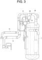
- Figure 3 is a schematically side view illustrating a structure in the vicinity of the accumulator and the suction path.
- Figure 3 shows the accumulator 7 in a transparent manner for the convenience of viewing.
- the accumulator 7 encloses a U-shaped tube, and the refrigerant flowing into the accumulator 7 passes through the inside of the U-shaped tube. Oil delivered through the second piping 53 is once stored outside the U-shaped tube. An orifice (small hole) is provided on the lower side of the U-shaped tube, so that the refrigerant and oil stored outside the U-shaped tube are gradually drawn into the inside of the U-shaped tube through the orifice. A discharge port of the U-shaped tube is connected to the suction path 50 upside the accumulator 7.
- the suction path 50 to deliver the refrigerant to the compressors 2 leads from the accumulator 7.
- the suction path 50 has the branch part 51 located above the accumulator 7 in the vertical direction.
- the first suction path 71 leading from the branch part 51 has a first upward extending part 71a extending upward, a first downward extending part 71c extending downward, and a first connection part 71b connecting between the first upward extending part 71a and the first downward extending part 71c.
- the first oil return piping 21 is connected to the first upward extending part 71a.
- a shape of the first connection part 71b is not limited and may be variable to some extent in the vertical direction.
- the first suction path 71 has the first upward extending part 71a, the first connection part 71b, and the first downward extending part 71c in the stated order along the refrigerant delivery direction between the upstream side where the branch part 51 is located and the downstream side where the first compressor 2a is located.
- the refrigerant flows along the delivery direction, but while the system is turned off, the refrigerant moves down by gravity. Namely, the refrigerant returns upstream at the first upward extending part 71a, it does not move significantly at the first connection part 71b, as well as it moves downstream at the first downward extending part 71c.
- the second piping 53 is connected to the branch part 51 located below the oil return piping 20 (the first oil return piping 21) in the vertical direction. Accordingly, in a state where the compressors 2 are stopped, oil flowing in through the oil return piping 20 returns to the accumulator 7 through the branch part 51 and the second piping 53. Namely, this makes it possible to be such a structure through which oil naturally returns without providing an additional power source.
- Each of the second suction path 72 and the third suction path 73 has a shape substantially similar to the first suction path 71, and the second suction path and the third suction path respectively have the second upward extending part 72a and the third upward extending part 73a, which correspond to the first upward extending part 71a, and the second connection part 72b and the third connection part 73b, which correspond to the first connection part 71b, as well as the second downward extending part 72c and the third downward extending part 73c, which correspond to the first downward extending part 71c.
- Figure 4 is an explanatory diagram illustrating variations of the degree of opening of the bypass valve and a rotation speed of a compressor over time.
- Figure 4 shows a degree of valve opening change characteristic line K1, which indicates a time-change in the degree of valve opening of the bypass valve 13, and a rotation speed change characteristic line R1, which indicates a time-change in the rotation speed of the compressors 2, and the horizontal axis represents a lapse of time.
- the degree of valve opening change characteristic line K1 the higher the vertical axis goes, the greater the degree of opening becomes, as well as with respect to the rotation speed change characteristic line R1, the higher the vertical axis goes, the greater the rotation speed becomes.
- the rotation speed of the compressors 2 may be a rough value, and thus a slight error is allowed.
- a time when the system gets started is shown as "0".
- the bypass valve 13 is set to an upper limit degree of valve opening (upper limit degree of valve opening Km), and the rotation speed of the compressors is set to zero.
- the rotation speed of the compressors 2 increases over time, and it reaches a stable rotation speed (stable rotation speed Rr) at time “T1.”
- the stable rotation speed Rr is maintained thereafter.
- the bypass valve 13 is set to the upper limit degree of valve opening Km until the time "T1", and after the time "T1", the valve is gradually closed (the degree of valve opening is reduced).
- the bypass valve 13 is controlled so that the degree of valve opening thereof is reduced over time after the heat pump 1 is started. While the bypass valve 13 is opened, as the gaseous refrigerant is delivered to the suction path 50 through the bypass circuit 30, it is possible to prevent excessive oil from flowing into. After the lump of oil is diminished by flowing oil gradually, by decreasing the delivery amount of the gaseous refrigerant to control so that the proper amount of oil is delivered, a normal operating environment of the system can be returned.
- Figure 4 shows a part of an operation transition when the system gets started, and the rotation speed of the compressors 2 may be controlled to exceed the stable rotation speed Rr as appropriate thereafter.
- the bypass valve 13, in which the degree of valve opening is linearly decreased is illustrated as an example, it is not limited thereto, and the degree of valve opening may be decreased in a step by step manner or the like if only the bypass valve 13 is closed finally.
Landscapes
- Engineering & Computer Science (AREA)
- Physics & Mathematics (AREA)
- Mechanical Engineering (AREA)
- Thermal Sciences (AREA)
- General Engineering & Computer Science (AREA)
- Chemical & Material Sciences (AREA)
- Analytical Chemistry (AREA)
- Power Engineering (AREA)
- Compressor (AREA)
- Compression-Type Refrigeration Machines With Reversible Cycles (AREA)
Abstract
Description
- The present invention relates to a heat pump including an accumulator connected to a compressor.
- Conventionally, it is known in a heat pump that if there is a liquid refrigerant around a compressor when the compressor gets started, it is concerned that the compressor is damaged by the liquid refrigerant. To suppress such a problem, a method of providing a heater on the compressor to warm up the compressor has been proposed (see, for example, Patent Literature 1).
- Patent Literature 1:
Japanese Patent Laid-Open Publication No. 2016-173201 - The heat pump disclosed in
Patent Literature 1 is provided with a compressor and a heater for the compressor, and an alarm is notified when an energization duration period of the heater for the compressor elapses a predetermined time. In addition, an accumulator is provided in a suction path of the compressor. In the heat pump mentioned above, it is often the case where while a system is turned off, oil in the accumulator accumulates in a piping connecting the compressor and the accumulator via an orifice. In such an event, there is a problem that if turning on the heat pump, the oil accumulated in the piping flows into the compressor as an oil lump, so that it causes the compressor to be damaged. - The present invention is made to solve the problem mentioned above, and an object of the invention is to provide a heat pump capable of preventing a compressor from being damaged by delivering hot gas together with a refrigerant when turning on the system.
- A heat pump according to the present invention includes: a compressor; an oil separator provided in a discharge path of the compressor; and an accumulator connected to the compressor via a suction path, wherein a bypass circuit to deliver a gaseous refrigerant separated with the oil separator is provided, and the bypass circuit is connected to the suction path.
- The heat pump according to the present invention may be configured such that a valve is provided in the bypass circuit, and the valve is controlled so that a degree of opening of the valve is decreased over time after the heat pump is started.
- The heat pump according to the present invention may be configured such that a first piping to deliver oil separated with the oil separator to the compressor is provided, and the first piping is connected to the suction path above the accumulator in a vertical direction.
- The heat pump according to the present invention may be configured such that the suction path has an upward extending part extending upward, a downward extending part extending downward, and a connection part to connect the upward extending part and the downward extending part, the upward extending part, the connection part, and the downward extending part are provided in the suction path in a stated order from an upstream side along a delivery direction of a refrigerant, and the first piping is connected to the upward extending part.
- The heat pump according to the present invention may be configured such that the suction path has a plurality of paths and a branch part that connects to the plurality of paths, a second piping to return oil to the accumulator is connected to the branch part, and the second piping is connected to the suction path below the first piping in the vertical direction.
- The heat pump according to the present invention may be configured such that a filter is housed in the branch part.
- The heat pump according to the present invention may be configured such that an oil path through which oil delivered from the oil separator flows and an oil sensor to detect an amount of oil flowing through the oil path are provided, and the oil path is connected to the bypass circuit.
- According to the present invention, even if oil is stored in a piping of the accumulator when getting started, since the gaseous refrigerant flowing in from the bypass circuit is mixed with oil, this makes it possible to prevent oil from rushing into the compressor and damaging the same.
-
- [
Figure 1] Figure 1 shows a simplified circuit diagram of a refrigerant circuit of a heat pump according to an embodiment of the present invention. - [
Figure 2] Figure 2 shows a schematically perspective view illustrating a structure in the vicinity of an accumulator and a suction path. - [
Figure 3] Figure 3 shows a schematically side view illustrating a structure in the vicinity of the accumulator and the suction path. - [
Figure 4] Figure 4 shows an explanatory diagram illustrating variations of a degree of opening of a bypass valve and a rotation speed of a compressor over time. - Now, a heat pump according to an embodiment of the present invention will be described below with reference to the drawings.
-
Figure 1 is a simplified circuit diagram illustrating a refrigerant circuit of a heat pump according to an embodiment of the present invention. - The
heat pump 1 has an outdoor unit to perform heat exchange with outdoor air and an indoor unit to perform heat exchange with indoor air. The outdoor unit includes compressors 2 (afirst compressor 2a, asecond compressor 2b, and athird compressor 2c), an oil separator 3, a four-way valve 4, an outdoor heat exchanger 5, anaccumulator 7, and anoutdoor expansion valve 11. The indoor unit has an indoor heat exchanger 6 and anindoor expansion valve 12. - The
first compressor 2a, thesecond compressor 2b, and thethird compressor 2c is driven with a driving source such as a gas engine, for example. The threecompressors 2 are configured to be driven with a single gas engine via a belt or a flywheel, or each of them may be selectively driven by providing a clutch. Thecompressors 2 are not limited thereto, and they may be electric compressors which can be driven electrically. A discharge path of thefirst compressor 2a (first discharge path 41), a discharge path of thesecond compressor 2b (second discharge path 42), and a discharge path of thethird compressor 2c (third discharge path 43) are integrated with afluid merging part 44 into asingle gas path 40. - High temperature and high pressure gaseous refrigerant discharged from the
compressors 2 are directed to the outdoor heat exchanger 5 or the indoor heat exchanger 6 with the four-way valve 4. During a heating operation (solid line) the four-way valve 4 delivers the gaseous refrigerant to the indoor heat exchanger 6, and during cooling operation (one-dot chain line) the four-way valve 4 delivers the gaseous refrigerant to the outdoor heat exchanger 5. - During the heating operation, the indoor heat exchanger 6 transfers heat from the refrigerant to the indoor air and causes the gaseous refrigerant to change into a liquid state with low temperature and high pressure. Then, the refrigerant is delivered to the outdoor heat exchanger 5 via the
indoor expansion valve 12 and theoutdoor expansion valve 11. A degree of opening of each of theindoor expansion valve 12 and theoutdoor expansion valve 11 is controlled by a controller or the like where appropriate. - During the heating operation, the
outdoor expansion valve 11 expands the liquid refrigerant and causes the liquid refrigerant to change into a liquid state (fog state) with low temperature and low pressure. Then, the outdoor heat exchanger 5 transfers heat from the outdoor air to the refrigerant and causes the refrigerant to change into a gaseous state with low temperature and low pressure. After passing through the outdoor heat exchanger 5, the refrigerant passes through the four-way valve 4 and is delivered to asuction path 50 of thecompressors 2. - The
accumulator 7 is provided in a path between the four-way valve 4 and thecompressors 2. Theaccumulator 7 temporarily stores the gaseous refrigerant. The gaseous refrigerant contains a small amount of a liquid refrigerant. These are separated in theaccumulator 7, and the liquid refrigerant is accumulated in theaccumulator 7. - The
suction path 50 connecting theaccumulator 7 and thecompressors 2 has thebranch part 51 connected to a plurality of paths and is branched into three paths (afirst suction path 71, asecond suction path 72, and a third suction path 73) via thebranch part 51. Thefirst suction path 71, thesecond suction path 72, and thethird suction path 73 are connected to thefirst compressor 2a, thesecond compressor 2b, and thethird compressor 2c, respectively. The structure in the vicinity of thesuction path 50 will be described in detail with reference toFigure 2 later. - A
filter 52 is housed in thebranch part 51 to adsorb a foreign matter contained in the refrigerant. By providing thefilter 52, dirt from the refrigerant and oil can be removed as well as the refrigerant and the oil can be kept clean. In addition, abranch part 51 from which the path branches can handle multiple paths at a single location, this makes it possible to preventextra filters 52 from being provided. - On the other hand, during a cooling operation, the high temperature and high pressure gaseous refrigerant discharged from the
compressors 2 are delivered via the four-way valve 4 to the outdoor heat exchanger 5 which performs heat exchange with the outdoor air to bring the refrigerant into a low temperature and high pressure liquid state. The refrigerant having passed through the outdoor heat exchanger 5 is brought into a low temperature and low pressure liquid state (fog state) by passing through theindoor expansion valve 12. Then, the refrigerant is delivered to the indoor heat exchanger 6 which performs heat exchange with the indoor air to bring the refrigerant into a low temperature and low pressure gaseous state. The refrigerant delivered from the indoor heat exchanger 6 is then delivered to thesuction path 50 of thecompressors 2 after passing through the four-way valve 4 and theaccumulator 7. - The oil separator 3 is provided between a discharge path of the
compressors 2 and the four-way valve 4. The oil separator 3 separates oil contained in the refrigerant. The oil separator 3 is connected to an oil return piping 20 (as an example of a first piping) for supplying the separated oil to thecompressors 2. Theoil return piping 20 is branched into three pipings, a firstoil return piping 21, a second oil return piping 22, and a thirdoil return piping 23, which correspond to thefirst suction path 71, thesecond suction path 72, and thethird suction path 73, respectively. Specifically, the firstoil return piping 21, the second oil return piping 22, and the thirdoil return piping 23 are connected to thefirst suction path 71, thesecond suction path 72, and thethird suction path 73, respectively. The first oil return piping 21, the second oil return piping 22, and the third oil return piping 23 may be each provided with a solenoid valve or the like to control a supply of oil separately. - The oil separator 3 is also connected to a
bypass circuit 30 thorough which the separated gas refrigerant (hot gas) is delivered. Thebypass circuit 30 is connected in thesuction path 50 between theaccumulator 7 and thebranch part 51. A bypass valve 13 (as an example of a valve), which controls the degree of valve opening and adjusts the flow rate of the gaseous refrigerant to be delivered, is provided in thebypass circuit 30. - In addition, an
oil path 60 independent of the oil return piping 20, through which oil passes, is connected to the oil separator 3. Theoil path 60 is connected to thebypass circuit 30, and by causing oil to pass through theoil path 60, oil can be delivered to thefilter 52 housed in thebranch part 51. By delivering an adequate amount of oil, performance of adsorbing debris of thefilter 52 can be improved. Anoil sensor 15 to detect the amount of oil passing through theoil path 60 and anoil valve 14 to control the delivery of oil are provided in theoil path 60. By providing theoil path 60, while the amount of oil can be detected by theoil sensor 15, oil can be delivered to the filter through thebypass circuit 30. - A
second piping 53, which returns oil to theaccumulator 7, is connected to thebranch part 51. Oil stored in thebranch part 51 is delivered through thesecond piping 53 and accumulated in theaccumulator 7. - In the
heat pump 1, there is a case where oil is stored in theaccumulator 7 while a system is turned off. According to this embodiment, thesuction path 50 reaching thecompressors 2 is connected to thebypass circuit 30. Even if oil is stored in a piping of theaccumulator 7 when getting started, since the gaseous refrigerant flowing in from thebypass circuit 30 is mixed with oil, this makes it possible to prevent oil from rushing into thecompressors 2 and damaging the same. -
Figure 2 is a schematically perspective view illustrating a structure in the vicinity of the accumulator and the suction path, andFigure 3 is a schematically side view illustrating a structure in the vicinity of the accumulator and the suction path.Figure 3 shows theaccumulator 7 in a transparent manner for the convenience of viewing. - The
accumulator 7 encloses a U-shaped tube, and the refrigerant flowing into theaccumulator 7 passes through the inside of the U-shaped tube. Oil delivered through thesecond piping 53 is once stored outside the U-shaped tube. An orifice (small hole) is provided on the lower side of the U-shaped tube, so that the refrigerant and oil stored outside the U-shaped tube are gradually drawn into the inside of the U-shaped tube through the orifice. A discharge port of the U-shaped tube is connected to thesuction path 50 upside theaccumulator 7. - As mentioned above, the
suction path 50 to deliver the refrigerant to thecompressors 2 leads from theaccumulator 7. Thesuction path 50 has thebranch part 51 located above theaccumulator 7 in the vertical direction. Thefirst suction path 71 leading from thebranch part 51 has a first upward extendingpart 71a extending upward, a first downward extendingpart 71c extending downward, and afirst connection part 71b connecting between the first upward extendingpart 71a and the first downward extendingpart 71c. The first oil return piping 21 is connected to the first upward extendingpart 71a. A shape of thefirst connection part 71b is not limited and may be variable to some extent in the vertical direction. - The
first suction path 71 has the first upward extendingpart 71a, thefirst connection part 71b, and the first downward extendingpart 71c in the stated order along the refrigerant delivery direction between the upstream side where thebranch part 51 is located and the downstream side where thefirst compressor 2a is located. Upon the system gets started, although the refrigerant (oil) flows along the delivery direction, but while the system is turned off, the refrigerant moves down by gravity. Namely, the refrigerant returns upstream at the first upward extendingpart 71a, it does not move significantly at thefirst connection part 71b, as well as it moves downstream at the first downward extendingpart 71c. Therefore, while thecompressors 2 are stopped, oil flowing into the first upward extendingpart 71a returns to theaccumulator 7, and thus it is possible to prevent oil from flowing into thecompressors 2. Furthermore, since oil flowing in through the first oil return piping 21 naturally flows downward, it is possible to prevent from producing an oil lump. - Furthermore, the
second piping 53 is connected to thebranch part 51 located below the oil return piping 20 (the first oil return piping 21) in the vertical direction. Accordingly, in a state where thecompressors 2 are stopped, oil flowing in through the oil return piping 20 returns to theaccumulator 7 through thebranch part 51 and thesecond piping 53. Namely, this makes it possible to be such a structure through which oil naturally returns without providing an additional power source. - Each of the
second suction path 72 and thethird suction path 73 has a shape substantially similar to thefirst suction path 71, and the second suction path and the third suction path respectively have the second upward extendingpart 72a and the third upward extendingpart 73a, which correspond to the first upward extendingpart 71a, and thesecond connection part 72b and thethird connection part 73b, which correspond to thefirst connection part 71b, as well as the second downward extendingpart 72c and the third downward extendingpart 73c, which correspond to the first downward extendingpart 71c. Since the flow of the refrigerant in thesecond suction path 72 and thethird suction path 73 is the same as in thefirst suction path 71, a detail explanation thereof is omitted except that they are configured so that oil can return to theaccumulator 7 while thecompressors 2 are stopped. - Next, the control of the degree of opening of the
bypass valve 13 when the system gets started will be explained below with reference toFigure 4 . -
Figure 4 is an explanatory diagram illustrating variations of the degree of opening of the bypass valve and a rotation speed of a compressor over time. -
Figure 4 shows a degree of valve opening change characteristic line K1, which indicates a time-change in the degree of valve opening of thebypass valve 13, and a rotation speed change characteristic line R1, which indicates a time-change in the rotation speed of thecompressors 2, and the horizontal axis represents a lapse of time. With respect to the degree of valve opening change characteristic line K1, the higher the vertical axis goes, the greater the degree of opening becomes, as well as with respect to the rotation speed change characteristic line R1, the higher the vertical axis goes, the greater the rotation speed becomes. Taking into account of variation to some extent, the rotation speed of thecompressors 2 may be a rough value, and thus a slight error is allowed. - In
Figure 4 , a time when the system gets started is shown as "0". At time "0", thebypass valve 13 is set to an upper limit degree of valve opening (upper limit degree of valve opening Km), and the rotation speed of the compressors is set to zero. The rotation speed of thecompressors 2 increases over time, and it reaches a stable rotation speed (stable rotation speed Rr) at time "T1." The stable rotation speed Rr is maintained thereafter. Thebypass valve 13 is set to the upper limit degree of valve opening Km until the time "T1", and after the time "T1", the valve is gradually closed (the degree of valve opening is reduced). - Namely, the
bypass valve 13 is controlled so that the degree of valve opening thereof is reduced over time after theheat pump 1 is started. While thebypass valve 13 is opened, as the gaseous refrigerant is delivered to thesuction path 50 through thebypass circuit 30, it is possible to prevent excessive oil from flowing into. After the lump of oil is diminished by flowing oil gradually, by decreasing the delivery amount of the gaseous refrigerant to control so that the proper amount of oil is delivered, a normal operating environment of the system can be returned. -
Figure 4 shows a part of an operation transition when the system gets started, and the rotation speed of thecompressors 2 may be controlled to exceed the stable rotation speed Rr as appropriate thereafter. Furthermore, although thebypass valve 13, in which the degree of valve opening is linearly decreased, is illustrated as an example, it is not limited thereto, and the degree of valve opening may be decreased in a step by step manner or the like if only thebypass valve 13 is closed finally. - It should be noted that embodiments disclosed above are exemplary in all respects, and the invention is not limitedly construed on a basis thereof. Therefore, the technical scope of the present invention should not be construed based on only above described embodiments but be defined based on the statement of the claims. Furthermore, any changes and modifications within the meaning and range equivalent to the claims fall within the scope of the invention.
- This application claims the benefit of priority to
Japanese Patent Application No. 2020-053960 filed as of March 25, 2020 -
- 1 Heat pump
- 2 Compressor
- 3 Oil separator
- 4 Four-way valve
- 5 Outdoor heat exchanger
- 6 Indoor heat exchanger
- 7 Accumulator
- 11 Outdoor expansion valve
- 12 Indoor expansion valve
- 13 Bypass valve (an example of a valve)
- 14 Oil valve
- 15 Oil sensor
- 20 Oil return piping (an example of a first piping)
- 30 Bypass circuit
- 40 Gas path
- 44 Fluid merging part
- 50 Suction path
- 51 Branch part
- 52 Filter
- 53 Second piping
- 60 Oil path
- 71 First suction path
- 71a First upward extending part (an example of an upward extending part)
- 71b First connection part (an example of a connection part)
- 71c First downward extending part (an example of a downward extending part)
- 72 Second suction path
- 72a Second upward extending part (an example of an upward extending part)
- 72b Second connection part (an example of a connection part)
- 72c Second downward extending part (an example of a downward extending part)
- 73 Third suction path
- 73a Third upward extending part (an example of an upward extending part)
- 73b Third connection part (an example of a connection part)
- 73c Third downward extending part (an example of a downward extending part)
Claims (7)
- A heat pump comprising:a compressor;an oil separator provided in a discharge path of the compressor; andan accumulator connected to the compressor via a suction path,wherein the heat pump comprises a bypass circuit to deliver a gaseous refrigerant separated with the oil separator, andthe bypass circuit is connected to the suction path.
- The heat pump according to claim 1, whereina valve is provided in the bypass circuit, andthe valve is controlled so that a degree of opening of the valve is decreased over time after the heat pump is started.
- The heat pump according to claim 1 or 2 further comprisinga first piping to deliver oil separated with the oil separator to the compressor,wherein the first piping is connected to the suction path above the accumulator in a vertical direction.
- The heat pump according to claim 3, whereinthe suction path has an upward extending part extending upward, a downward extending part extending downward, and a connection part to connect the upward extending part and the downward extending part,the upward extending part, the connection part, and the downward extending part are provided in the suction path in a stated order from an upstream side along a delivery direction of a refrigerant, andthe first piping is connected to the upward extending part.
- The heat pump according to claim 4, whereinthe suction path has a plurality of paths and a branch part that connects to the plurality of paths,a second piping to return oil to the accumulator is connected to the branch part, andthe second piping is connected to the suction path below the first piping in the vertical direction.
- The heat pump according to claim 5, wherein
a filter is housed in the branch part. - The heat pump according to claim 6 further comprising:an oil path through which oil delivered from the oil separator flows; andan oil sensor to detect an amount of oil flowing through the oil path,wherein the oil path is connected to the bypass circuit.
Applications Claiming Priority (2)
| Application Number | Priority Date | Filing Date | Title |
|---|---|---|---|
| JP2020053960A JP7360349B2 (en) | 2020-03-25 | 2020-03-25 | heat pump |
| PCT/JP2021/008359 WO2021192884A1 (en) | 2020-03-25 | 2021-03-04 | Heat pump |
Publications (3)
| Publication Number | Publication Date |
|---|---|
| EP4130606A1 true EP4130606A1 (en) | 2023-02-08 |
| EP4130606A4 EP4130606A4 (en) | 2024-04-17 |
| EP4130606B1 EP4130606B1 (en) | 2025-09-17 |
Family
ID=77891271
Family Applications (1)
| Application Number | Title | Priority Date | Filing Date |
|---|---|---|---|
| EP21775276.5A Active EP4130606B1 (en) | 2020-03-25 | 2021-03-04 | Heat pump |
Country Status (6)
| Country | Link |
|---|---|
| US (1) | US12228315B2 (en) |
| EP (1) | EP4130606B1 (en) |
| JP (1) | JP7360349B2 (en) |
| KR (1) | KR20220157926A (en) |
| CN (1) | CN115244343A (en) |
| WO (1) | WO2021192884A1 (en) |
Families Citing this family (1)
| Publication number | Priority date | Publication date | Assignee | Title |
|---|---|---|---|---|
| DE112022004625T5 (en) | 2021-09-27 | 2024-08-29 | Hitachi Astemo, Ltd. | Vehicle control device and vehicle control system |
Family Cites Families (10)
| Publication number | Priority date | Publication date | Assignee | Title |
|---|---|---|---|---|
| US5369958A (en) * | 1992-10-15 | 1994-12-06 | Mitsubishi Denki Kabushiki Kaisha | Air conditioner |
| JPH09287834A (en) * | 1996-04-24 | 1997-11-04 | Mitsubishi Electric Corp | Operating method of air conditioner and air conditioner |
| JP3887587B2 (en) | 2002-08-26 | 2007-02-28 | ヤンマー株式会社 | air conditioner |
| KR100548281B1 (en) * | 2003-10-22 | 2006-02-02 | 엘지전자 주식회사 | Outdoor unit of air conditioner with a plurality of low pressure compressors |
| JP2006112668A (en) | 2004-10-12 | 2006-04-27 | Fujitsu General Ltd | Multi-room air conditioner outdoor unit |
| CN103038585B (en) | 2010-07-01 | 2016-08-03 | 东芝开利株式会社 | Cooling cycle system |
| JP5881282B2 (en) * | 2010-09-30 | 2016-03-09 | 三菱重工業株式会社 | Turbo refrigeration apparatus, control apparatus and control method thereof |
| JP6356083B2 (en) | 2015-03-17 | 2018-07-11 | ヤンマー株式会社 | heat pump |
| CN106969524B (en) * | 2016-12-29 | 2020-06-26 | 广东美的暖通设备有限公司 | Air-conditioning differential pressure balancing system and method for balancing air-conditioning differential pressure |
| JP7442989B2 (en) | 2018-09-19 | 2024-03-05 | キヤノン株式会社 | Imaging device, control method for the imaging device, and program |
-
2020
- 2020-03-25 JP JP2020053960A patent/JP7360349B2/en active Active
-
2021
- 2021-03-04 EP EP21775276.5A patent/EP4130606B1/en active Active
- 2021-03-04 CN CN202180005974.7A patent/CN115244343A/en active Pending
- 2021-03-04 WO PCT/JP2021/008359 patent/WO2021192884A1/en not_active Ceased
- 2021-03-04 US US17/913,999 patent/US12228315B2/en active Active
- 2021-03-04 KR KR1020227004614A patent/KR20220157926A/en active Pending
Also Published As
| Publication number | Publication date |
|---|---|
| EP4130606A4 (en) | 2024-04-17 |
| WO2021192884A1 (en) | 2021-09-30 |
| US20230135687A1 (en) | 2023-05-04 |
| KR20220157926A (en) | 2022-11-29 |
| JP7360349B2 (en) | 2023-10-12 |
| EP4130606B1 (en) | 2025-09-17 |
| US12228315B2 (en) | 2025-02-18 |
| JP2021156440A (en) | 2021-10-07 |
| CN115244343A (en) | 2022-10-25 |
Similar Documents
| Publication | Publication Date | Title |
|---|---|---|
| AU2003235228B2 (en) | Oil equalizing circuit for compression mechanisms, heat source unit for freezing device, and freezing device having the same | |
| US7143594B2 (en) | Control method for operating a refrigeration system | |
| KR101585948B1 (en) | Air conditioner | |
| EP1692439A1 (en) | Refrigerant system with controlled refrigerant charge amount | |
| US11739994B2 (en) | Apparatus and method for lubricant management in an electric vehicle | |
| EP3040635A1 (en) | Air conditioner | |
| EP1039250A2 (en) | Refrigerating cycle with a by-pass line | |
| CN109638377B (en) | Battery cooling system, vehicle battery swapping system, and battery cooling control method | |
| CN112088099B (en) | Refrigeration system for vehicles with refrigerant circuit with heat pump function | |
| US5182919A (en) | Oil recovery system for closed type centrifugal refrigerating machine | |
| EP4130606B1 (en) | Heat pump | |
| CN114198922A (en) | Liquid supply system of compressor | |
| JP2016173201A (en) | Heat pump | |
| US9163862B2 (en) | Receiver fill valve and control method | |
| KR100592953B1 (en) | Air conditioner | |
| CN114508433A (en) | Control method of fuel supply system | |
| US12442572B2 (en) | Heat pump | |
| CN109307385B (en) | Air conditioning system, compression oil supply device and control method thereof | |
| KR100565465B1 (en) | How to balance oil pressure and control air conditioner | |
| EP3604973B1 (en) | Air conditioner | |
| CN120112738A (en) | Equipment for hydraulic systems, hydraulic systems, power modules for motor vehicles | |
| JP2000038905A (en) | Hydraulic controller | |
| JP2004176933A (en) | Oil equalizing circuit of compression mechanism, heat source unit of air conditioner, and air conditioner provided with the same | |
| JPH0641751B2 (en) | Twin type compression device | |
| CN119374256A (en) | Air conditioner and control method thereof, controller, air conditioning system and storage medium |
Legal Events
| Date | Code | Title | Description |
|---|---|---|---|
| STAA | Information on the status of an ep patent application or granted ep patent |
Free format text: STATUS: THE INTERNATIONAL PUBLICATION HAS BEEN MADE |
|
| PUAI | Public reference made under article 153(3) epc to a published international application that has entered the european phase |
Free format text: ORIGINAL CODE: 0009012 |
|
| STAA | Information on the status of an ep patent application or granted ep patent |
Free format text: STATUS: REQUEST FOR EXAMINATION WAS MADE |
|
| 17P | Request for examination filed |
Effective date: 20221011 |
|
| AK | Designated contracting states |
Kind code of ref document: A1 Designated state(s): AL AT BE BG CH CY CZ DE DK EE ES FI FR GB GR HR HU IE IS IT LI LT LU LV MC MK MT NL NO PL PT RO RS SE SI SK SM TR |
|
| DAV | Request for validation of the european patent (deleted) | ||
| DAX | Request for extension of the european patent (deleted) | ||
| A4 | Supplementary search report drawn up and despatched |
Effective date: 20240319 |
|
| RIC1 | Information provided on ipc code assigned before grant |
Ipc: F25B 43/02 20060101ALI20240313BHEP Ipc: F25B 43/00 20060101ALI20240313BHEP Ipc: F25B 41/20 20210101ALI20240313BHEP Ipc: F25B 1/00 20060101AFI20240313BHEP |
|
| GRAP | Despatch of communication of intention to grant a patent |
Free format text: ORIGINAL CODE: EPIDOSNIGR1 |
|
| STAA | Information on the status of an ep patent application or granted ep patent |
Free format text: STATUS: GRANT OF PATENT IS INTENDED |
|
| INTG | Intention to grant announced |
Effective date: 20250428 |
|
| GRAS | Grant fee paid |
Free format text: ORIGINAL CODE: EPIDOSNIGR3 |
|
| GRAA | (expected) grant |
Free format text: ORIGINAL CODE: 0009210 |
|
| STAA | Information on the status of an ep patent application or granted ep patent |
Free format text: STATUS: THE PATENT HAS BEEN GRANTED |
|
| AK | Designated contracting states |
Kind code of ref document: B1 Designated state(s): AL AT BE BG CH CY CZ DE DK EE ES FI FR GB GR HR HU IE IS IT LI LT LU LV MC MK MT NL NO PL PT RO RS SE SI SK SM TR |
|
| REG | Reference to a national code |
Ref country code: GB Ref legal event code: FG4D |
|
| REG | Reference to a national code |
Ref country code: CH Ref legal event code: EP |
|
| REG | Reference to a national code |
Ref country code: IE Ref legal event code: FG4D |
|
| REG | Reference to a national code |
Ref country code: DE Ref legal event code: R096 Ref document number: 602021038820 Country of ref document: DE |
|
| PG25 | Lapsed in a contracting state [announced via postgrant information from national office to epo] |
Ref country code: NO Free format text: LAPSE BECAUSE OF FAILURE TO SUBMIT A TRANSLATION OF THE DESCRIPTION OR TO PAY THE FEE WITHIN THE PRESCRIBED TIME-LIMIT Effective date: 20251217 |
|
| REG | Reference to a national code |
Ref country code: LT Ref legal event code: MG9D |
|
| PG25 | Lapsed in a contracting state [announced via postgrant information from national office to epo] |
Ref country code: FI Free format text: LAPSE BECAUSE OF FAILURE TO SUBMIT A TRANSLATION OF THE DESCRIPTION OR TO PAY THE FEE WITHIN THE PRESCRIBED TIME-LIMIT Effective date: 20250917 |
|
| PG25 | Lapsed in a contracting state [announced via postgrant information from national office to epo] |
Ref country code: HR Free format text: LAPSE BECAUSE OF FAILURE TO SUBMIT A TRANSLATION OF THE DESCRIPTION OR TO PAY THE FEE WITHIN THE PRESCRIBED TIME-LIMIT Effective date: 20250917 |
|
| PG25 | Lapsed in a contracting state [announced via postgrant information from national office to epo] |
Ref country code: GR Free format text: LAPSE BECAUSE OF FAILURE TO SUBMIT A TRANSLATION OF THE DESCRIPTION OR TO PAY THE FEE WITHIN THE PRESCRIBED TIME-LIMIT Effective date: 20251218 |
|
| PG25 | Lapsed in a contracting state [announced via postgrant information from national office to epo] |
Ref country code: SE Free format text: LAPSE BECAUSE OF FAILURE TO SUBMIT A TRANSLATION OF THE DESCRIPTION OR TO PAY THE FEE WITHIN THE PRESCRIBED TIME-LIMIT Effective date: 20250917 |
|
| REG | Reference to a national code |
Ref country code: NL Ref legal event code: MP Effective date: 20250917 |
|
| PG25 | Lapsed in a contracting state [announced via postgrant information from national office to epo] |
Ref country code: LV Free format text: LAPSE BECAUSE OF FAILURE TO SUBMIT A TRANSLATION OF THE DESCRIPTION OR TO PAY THE FEE WITHIN THE PRESCRIBED TIME-LIMIT Effective date: 20250917 |
|
| PG25 | Lapsed in a contracting state [announced via postgrant information from national office to epo] |
Ref country code: BG Free format text: LAPSE BECAUSE OF FAILURE TO SUBMIT A TRANSLATION OF THE DESCRIPTION OR TO PAY THE FEE WITHIN THE PRESCRIBED TIME-LIMIT Effective date: 20250917 |
|
| PG25 | Lapsed in a contracting state [announced via postgrant information from national office to epo] |
Ref country code: RS Free format text: LAPSE BECAUSE OF FAILURE TO SUBMIT A TRANSLATION OF THE DESCRIPTION OR TO PAY THE FEE WITHIN THE PRESCRIBED TIME-LIMIT Effective date: 20251217 |
|
| PG25 | Lapsed in a contracting state [announced via postgrant information from national office to epo] |
Ref country code: NL Free format text: LAPSE BECAUSE OF FAILURE TO SUBMIT A TRANSLATION OF THE DESCRIPTION OR TO PAY THE FEE WITHIN THE PRESCRIBED TIME-LIMIT Effective date: 20250917 |
|
| REG | Reference to a national code |
Ref country code: AT Ref legal event code: MK05 Ref document number: 1838589 Country of ref document: AT Kind code of ref document: T Effective date: 20250917 |
|
| PG25 | Lapsed in a contracting state [announced via postgrant information from national office to epo] |
Ref country code: SM Free format text: LAPSE BECAUSE OF FAILURE TO SUBMIT A TRANSLATION OF THE DESCRIPTION OR TO PAY THE FEE WITHIN THE PRESCRIBED TIME-LIMIT Effective date: 20250917 |
|
| PGFP | Annual fee paid to national office [announced via postgrant information from national office to epo] |
Ref country code: GB Payment date: 20260324 Year of fee payment: 6 |
|
| PG25 | Lapsed in a contracting state [announced via postgrant information from national office to epo] |
Ref country code: ES Free format text: LAPSE BECAUSE OF FAILURE TO SUBMIT A TRANSLATION OF THE DESCRIPTION OR TO PAY THE FEE WITHIN THE PRESCRIBED TIME-LIMIT Effective date: 20250917 |
|
| PGFP | Annual fee paid to national office [announced via postgrant information from national office to epo] |
Ref country code: DE Payment date: 20260319 Year of fee payment: 6 |
|
| PG25 | Lapsed in a contracting state [announced via postgrant information from national office to epo] |
Ref country code: AT Free format text: LAPSE BECAUSE OF FAILURE TO SUBMIT A TRANSLATION OF THE DESCRIPTION OR TO PAY THE FEE WITHIN THE PRESCRIBED TIME-LIMIT Effective date: 20250917 |
|
| PGFP | Annual fee paid to national office [announced via postgrant information from national office to epo] |
Ref country code: IT Payment date: 20260324 Year of fee payment: 6 |
|
| PG25 | Lapsed in a contracting state [announced via postgrant information from national office to epo] |
Ref country code: IS Free format text: LAPSE BECAUSE OF FAILURE TO SUBMIT A TRANSLATION OF THE DESCRIPTION OR TO PAY THE FEE WITHIN THE PRESCRIBED TIME-LIMIT Effective date: 20260117 |
|
| PG25 | Lapsed in a contracting state [announced via postgrant information from national office to epo] |
Ref country code: CZ Free format text: LAPSE BECAUSE OF FAILURE TO SUBMIT A TRANSLATION OF THE DESCRIPTION OR TO PAY THE FEE WITHIN THE PRESCRIBED TIME-LIMIT Effective date: 20250917 Ref country code: PT Free format text: LAPSE BECAUSE OF FAILURE TO SUBMIT A TRANSLATION OF THE DESCRIPTION OR TO PAY THE FEE WITHIN THE PRESCRIBED TIME-LIMIT Effective date: 20260119 |
|
| PG25 | Lapsed in a contracting state [announced via postgrant information from national office to epo] |
Ref country code: PL Free format text: LAPSE BECAUSE OF FAILURE TO SUBMIT A TRANSLATION OF THE DESCRIPTION OR TO PAY THE FEE WITHIN THE PRESCRIBED TIME-LIMIT Effective date: 20250917 |
|
| PG25 | Lapsed in a contracting state [announced via postgrant information from national office to epo] |
Ref country code: EE Free format text: LAPSE BECAUSE OF FAILURE TO SUBMIT A TRANSLATION OF THE DESCRIPTION OR TO PAY THE FEE WITHIN THE PRESCRIBED TIME-LIMIT Effective date: 20250917 Ref country code: SK Free format text: LAPSE BECAUSE OF FAILURE TO SUBMIT A TRANSLATION OF THE DESCRIPTION OR TO PAY THE FEE WITHIN THE PRESCRIBED TIME-LIMIT Effective date: 20250917 |