EP4130594A1 - Temperature adjustment device, control method therefor, control apparatus thereof, and storage medium - Google Patents
Temperature adjustment device, control method therefor, control apparatus thereof, and storage medium Download PDFInfo
- Publication number
- EP4130594A1 EP4130594A1 EP21902185.4A EP21902185A EP4130594A1 EP 4130594 A1 EP4130594 A1 EP 4130594A1 EP 21902185 A EP21902185 A EP 21902185A EP 4130594 A1 EP4130594 A1 EP 4130594A1
- Authority
- EP
- European Patent Office
- Prior art keywords
- temperature
- conditioning apparatus
- current
- operating parameter
- temperature conditioning
- Prior art date
- Legal status (The legal status is an assumption and is not a legal conclusion. Google has not performed a legal analysis and makes no representation as to the accuracy of the status listed.)
- Pending
Links
Images


Classifications
-
- F—MECHANICAL ENGINEERING; LIGHTING; HEATING; WEAPONS; BLASTING
- F24—HEATING; RANGES; VENTILATING
- F24F—AIR-CONDITIONING; AIR-HUMIDIFICATION; VENTILATION; USE OF AIR CURRENTS FOR SCREENING
- F24F11/00—Control or safety arrangements
- F24F11/62—Control or safety arrangements characterised by the type of control or by internal processing, e.g. using fuzzy logic, adaptive control or estimation of values
- F24F11/63—Electronic processing
-
- F—MECHANICAL ENGINEERING; LIGHTING; HEATING; WEAPONS; BLASTING
- F24—HEATING; RANGES; VENTILATING
- F24F—AIR-CONDITIONING; AIR-HUMIDIFICATION; VENTILATION; USE OF AIR CURRENTS FOR SCREENING
- F24F11/00—Control or safety arrangements
- F24F11/30—Control or safety arrangements for purposes related to the operation of the system, e.g. for safety or monitoring
- F24F11/46—Improving electric energy efficiency or saving
-
- F—MECHANICAL ENGINEERING; LIGHTING; HEATING; WEAPONS; BLASTING
- F24—HEATING; RANGES; VENTILATING
- F24F—AIR-CONDITIONING; AIR-HUMIDIFICATION; VENTILATION; USE OF AIR CURRENTS FOR SCREENING
- F24F11/00—Control or safety arrangements
- F24F11/70—Control systems characterised by their outputs; Constructional details thereof
- F24F11/72—Control systems characterised by their outputs; Constructional details thereof for controlling the supply of treated air, e.g. its pressure
- F24F11/74—Control systems characterised by their outputs; Constructional details thereof for controlling the supply of treated air, e.g. its pressure for controlling air flow rate or air velocity
- F24F11/77—Control systems characterised by their outputs; Constructional details thereof for controlling the supply of treated air, e.g. its pressure for controlling air flow rate or air velocity by controlling the speed of ventilators
-
- F—MECHANICAL ENGINEERING; LIGHTING; HEATING; WEAPONS; BLASTING
- F24—HEATING; RANGES; VENTILATING
- F24F—AIR-CONDITIONING; AIR-HUMIDIFICATION; VENTILATION; USE OF AIR CURRENTS FOR SCREENING
- F24F11/00—Control or safety arrangements
- F24F11/70—Control systems characterised by their outputs; Constructional details thereof
- F24F11/80—Control systems characterised by their outputs; Constructional details thereof for controlling the temperature of the supplied air
-
- F—MECHANICAL ENGINEERING; LIGHTING; HEATING; WEAPONS; BLASTING
- F24—HEATING; RANGES; VENTILATING
- F24F—AIR-CONDITIONING; AIR-HUMIDIFICATION; VENTILATION; USE OF AIR CURRENTS FOR SCREENING
- F24F11/00—Control or safety arrangements
- F24F11/70—Control systems characterised by their outputs; Constructional details thereof
- F24F11/80—Control systems characterised by their outputs; Constructional details thereof for controlling the temperature of the supplied air
- F24F11/83—Control systems characterised by their outputs; Constructional details thereof for controlling the temperature of the supplied air by controlling the supply of heat-exchange fluids to heat-exchangers
-
- F—MECHANICAL ENGINEERING; LIGHTING; HEATING; WEAPONS; BLASTING
- F24—HEATING; RANGES; VENTILATING
- F24F—AIR-CONDITIONING; AIR-HUMIDIFICATION; VENTILATION; USE OF AIR CURRENTS FOR SCREENING
- F24F2110/00—Control inputs relating to air properties
- F24F2110/10—Temperature
-
- F—MECHANICAL ENGINEERING; LIGHTING; HEATING; WEAPONS; BLASTING
- F24—HEATING; RANGES; VENTILATING
- F24F—AIR-CONDITIONING; AIR-HUMIDIFICATION; VENTILATION; USE OF AIR CURRENTS FOR SCREENING
- F24F2140/00—Control inputs relating to system states
- F24F2140/50—Load
-
- G—PHYSICS
- G05—CONTROLLING; REGULATING
- G05B—CONTROL OR REGULATING SYSTEMS IN GENERAL; FUNCTIONAL ELEMENTS OF SUCH SYSTEMS; MONITORING OR TESTING ARRANGEMENTS FOR SUCH SYSTEMS OR ELEMENTS
- G05B2219/00—Program-control systems
- G05B2219/20—Pc systems
- G05B2219/26—Pc applications
- G05B2219/2614—HVAC, heating, ventillation, climate control
-
- Y—GENERAL TAGGING OF NEW TECHNOLOGICAL DEVELOPMENTS; GENERAL TAGGING OF CROSS-SECTIONAL TECHNOLOGIES SPANNING OVER SEVERAL SECTIONS OF THE IPC; TECHNICAL SUBJECTS COVERED BY FORMER USPC CROSS-REFERENCE ART COLLECTIONS [XRACs] AND DIGESTS
- Y02—TECHNOLOGIES OR APPLICATIONS FOR MITIGATION OR ADAPTATION AGAINST CLIMATE CHANGE
- Y02B—CLIMATE CHANGE MITIGATION TECHNOLOGIES RELATED TO BUILDINGS, e.g. HOUSING, HOUSE APPLIANCES OR RELATED END-USER APPLICATIONS
- Y02B30/00—Energy efficient heating, ventilation or air conditioning [HVAC]
- Y02B30/70—Efficient control or regulation technologies, e.g. for control of refrigerant flow, motor or heating
Definitions
- the present disclosure relates to the technical field of temperature control, specifically to a temperature conditioning apparatus and a control method and control device therefor and a storage medium.
- the temperature conditioning apparatus especially an air conditioner, generally starts and stops frequently due to a mismatch between the output and a load for a building, where a ratio of a shutdown more than once per hour accounts for more than half therebetween. A frequent start-stop leads to higher energy consumption by the apparatus, thereby resulting in an energy loss.
- the present disclosure aims to solve at least one of the technical problems in the related art to a certain degree.
- a first object of the present disclosure is to provide a method for controlling a temperature conditioning apparatus.
- the method adjusts an operating status of the temperature conditioning apparatus according to a current demand load of a co-cooling/co-heating area and an operating parameter, realizing a detection for the demand load of the co-cooling/co-heating area, and a control for the temperature conditioning apparatus according to the detected demand load, thus reducing the number of start-stops of the temperature conditioning apparatus and avoiding a frequent start-stop, thereby making the temperature conditioning apparatus operate in energy saving.
- a second object of the present disclosure is to provide a device for controlling a temperature conditioning apparatus.
- a third object of the present disclosure is to provide a computer-readable storage medium.
- a fourth object of the present disclosure is to provide a temperature conditioning apparatus.
- the present disclosure provides in embodiments a method for controlling a temperature conditioning apparatus, including: acquiring a current demand load of a co-cooling/co-heating area where the temperature conditioning apparatus is located; acquiring a current operating parameter of the temperature conditioning apparatus; determining a target operating parameter of the temperature conditioning apparatus according to the current operating parameter and the current demand load; and adjusting an operating status of the temperature conditioning apparatus according to the target operating parameter.
- the present disclosure provides in embodiments a device for controlling a temperature conditioning apparatus, including: a first acquiring module, configured to acquire a current demand load of a co-cooling/co-heating area where the temperature conditioning apparatus is located; a second acquiring module, configured to acquire a current operating parameter of the temperature conditioning apparatus; a first determining module, configured to determine a target operating parameter of the temperature conditioning apparatus according to the current operating parameter and the current demand load; and a first adjusting module, configured to adjust an operating status of the temperature conditioning apparatus according to the target operating parameter.
- the present disclosure provides in embodiments a computer-readable storage medium having stored therein a computer program that, when executed by a processor, achieves a method for controlling a temperature conditioning apparatus according to the embodiments of the present disclosure in the first aspect.
- the present disclosure provides in embodiments a temperature conditioning apparatus, including a device for controlling a temperature conditioning apparatus according to the above embodiments of the present disclosure.
- a current demand load of a co-cooling/co-heating area where a temperature conditioning apparatus is located is acquired; a current operating parameter of the temperature conditioning apparatus is acquired; a target operating parameter of the temperature conditioning apparatus is determined according to the current operating parameter and the current demand load; and an operating status of the temperature conditioning apparatus is adjusted according to the target operating parameter.
- the operating status of the temperature conditioning apparatus is adjusted according to the current demand load of the co-cooling/co-heating area and the operating parameter, realizing a detection for the demand load of the co-cooling/co-heating area and a control for the temperature conditioning apparatus according to the detected demand load, thus reducing the number of the start-stops of the temperature conditioning apparatus and avoiding a frequent start-stop, thereby making the temperature conditioning apparatus operate in energy saving.
- the air conditioner generally starts and stops frequently due to a mismatch between a system output and a load for a building, where a ratio of a shutdown more than once per hour accounts for more than half therebetween. A frequent start-stop leads to higher energy consumption by the apparatus.
- an excessive output of the air conditioner is caused by an excessively high condensing temperature under a heating state or an excessively low evaporating temperature under a cooling state, at which the system does not operate at an optimal energy efficiency point based on meeting the load.
- the current temperature conditioning apparatus still fails to utilize the capability of a frequency conversion apparatus to achieve a more efficient operation.
- a main problem to be solved for the above is to acquire a demand load for a building and how to control the system to realize a high-efficient operation that matches the load, after the load is acquired.
- a demand energy of indoors is generally calculated, with a temperature difference between an intaking air temperature and a current set temperature, but this temperature difference does not reflect a load when the indoors reaches the set temperature; or with a load simulation through a complex simulation.
- the present disclosure provides in examples a method for controlling a temperature conditioning apparatus, which realizes a detection for the demand load of the co-cooling/co-heating area, and controls the temperature conditioning apparatus according to the detected demand load, thus avoiding a frequent start-stop of the temperature conditioning apparatus, thereby benefiting the temperature conditioning apparatus to operate at the optimal energy efficiency.
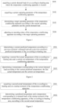
- Figure 1 is a flow chart showing a method for controlling a temperature conditioning apparatus according to examples of the present disclosure.
- the method includes the following steps S101-S104.
- the co-cooling/co-heating area refers to an area where the temperature conditioning apparatus is located that requires cooling and/or heating.
- the current demand load refers to a load which is required currently, i.e. a target load.
- the temperature conditioning apparatus may detect the demand load of the co-cooling/co-heating area in real time, thus realizing a real-time trace for the demand load.
- the current operating parameter is a parameter indicating an actual operating status of the temperature conditioning apparatus, such as a current environment temperature, a temperature of a heat exchanger, a rotate speed of an indoor fan and the like.
- the temperature conditioning apparatus may detect the current operating parameter of the temperature conditioning apparatus in real time, or may detect the current operating parameter of the temperature conditioning apparatus while detecting the demand load in real time, thus realizing a real-time trace for the operating parameter.
- a target operating parameter of the temperature conditioning apparatus is determined according to the current operating parameter and the current demand load.
- the target operating parameter of the temperature conditioning apparatus is determined according to the current operating parameter and the current demand load, such as a target temperature of the heat exchanger, a target rotate speed of the indoor fan and the like.
- an operating status of the temperature conditioning apparatus is adjusted according to the target operating parameter.
- the operating status of the temperature conditioning apparatus is adjusted to make an operating parameter of the temperature conditioning apparatus reach the target operating parameter, thus making the operating parameter of the temperature conditioning apparatus match the demand load of the co-cooling/co-heating area at the current moment, and avoiding the temperature conditioning apparatus from a frequent start-stop due to a mismatch between the operating parameter and the demand load, thereby benefiting the temperature conditioning apparatus to operate at the optimal energy efficiency based on the current demand load.
- the method adjusts the operating status of the temperature conditioning apparatus according to the current demand load of the co-cooling/co-heating area and the operating parameter, realizing a detection for the demand load of the co-cooling/co-heating area, and a control for the temperature conditioning apparatus according to the detected demand load, thus reducing the number of the start-stops of the temperature conditioning apparatus and avoiding a frequent start-stop, thereby making the temperature conditioning apparatus operate in energy saving.
- the current demand load may be acquired with a previous status parameter and a current status parameter.
- the current demand load may be acquired according to a previous operating parameter of the temperature conditioning apparatus, a previous demand load of the co-cooling/co-heating area, a current set temperature of the temperature conditioning apparatus and a current actual temperature of the co-cooling/co-heating area.
- the previous demand load may be a previous moment's demand load during the demand load is acquired.
- step S101 may include the following steps S201-S203.
- a current predicted temperature is determined according to a previous moment's demand load and a previous moment's predicted temperature of the co-cooling/co-heating area.
- the previous moment's demand load and the previous moment's predicted temperature of the co-cooling/co-heating area where the temperature conditioning apparatus is located may be acquired by calling the previous status parameter of the temperature conditioning apparatus, and the current predicted temperature is calculated according to the previous moment's demand load and the previous moment's predicted temperature.
- a current first actual temperature of the co-cooling/co-heating area and a current set temperature of the temperature conditioning apparatus are acquired.
- the current first actual temperature T 1 (n) of the co-cooling/co-heating area may be detected with a temperature sensor, and the current set temperature T set (n) of the temperature conditioning apparatus may be acquired by viewing a monitor of the temperature conditioning apparatus, where n represents the current moment.
- the temperature conditioning apparatus operates according to its set temperature T set (n), while influenced by other factors such as the environment temperature, the current first actual temperature of the co-cooling/co-heating area is T 1 (n), rather than T set (n).
- a temperature corresponding to the current demand load is determined according to the current predicted temperature, the first actual temperature and the current set temperature.
- T load,r (n) is the temperature corresponding to the current demand load, and a, b and c are pre-set known coefficients.
- the temperature corresponding to the current demand load of the co-cooling/co-heating area is calculated according to the previous moment's demand load and the previous moment's predicted temperature of the co-cooling/co-heating area, and the current first actual temperature of the co-cooling/co-heating area and the current set temperature of the temperature conditioning apparatus, thereby ensuring the reliability of acquiring the temperature corresponding to the demand load.
- the temperature corresponding to the current demand load is acquired according to a previous moment's operating status parameter and a current moment's operating status parameter.
- the predicted temperature of the co-cooling/co-heating area and the temperature corresponding to the demand load are both equal to the actual temperature of the co-cooling/co-heating area, such as an actual indoor temperature.
- the method for controlling the temperature conditioning apparatus may further include the following steps S301-S302.
- the temperature conditioning apparatus may be monitored for its open state in real time, and when the temperature conditioning apparatus is monitored to be started, the second actual temperature of the co-cooling/co-heating area may be acquired with the temperature sensor in time.
- the predicted temperature and the temperature corresponding to the demand load, at the startup moment of the temperature conditioning apparatus, of the co-cooling/co-heating area is determined according to the second actual temperature.
- the predicted temperature of the co-cooling/co-heating area and the temperature corresponding to the demand load are both equal to the second actual temperature
- the predicted temperature of the co-cooling/co-heating area and the temperature corresponding to the demand load, at the startup moment may be determined according to the second actual temperature, for a subsequent adjustment for the temperature conditioning apparatus.
- the predicted temperature and the temperature corresponding to the demand load, at the startup moment, of the co-cooling/co-heating area are determined by acquiring the actual temperature of the co-cooling/co-heating area, so as to adjust the temperature conditioning apparatus according to the temperature corresponding to the demand load.
- the trace for the demand load are not only performed during the operation of the temperature conditioning apparatus, but also performed at the startup moment of the temperature conditioning apparatus, thus realizing the real-time trace for the demand load, and the status parameter of the temperature conditioning apparatus is adjusted according to the demand load, thus ensuring the reliability of the acquired demand load, and effectively avoiding the temperature conditioning apparatus from the frequent start-stop, thereby benefiting the temperature conditioning apparatus to operate at the optimal energy efficiency.
- step S103 may include the following steps S401-S402.
- a current output energy of the temperature conditioning apparatus is determined according to the current operating parameter.
- the current output energy refers to a temperature variation value caused by an energy input for the temperature conditioning apparatus.
- the target operating parameter of the temperature conditioning apparatus is determined according to a matched-degree between the output energy and the demand load.
- the temperature variation value caused by the energy input for the temperature conditioning apparatus may be matched to a temperature variation value corresponding to the demand load, to obtain the matched-degree between the two, and according to the matched-degree, to determine the target operating parameter of the temperature conditioning apparatus, thus making the current output energy of the temperature conditioning apparatus match the current demand load of the co-cooling/co-heating area, i.e. make them equal, thereby avoiding the temperature conditioning apparatus from the frequent start-stop due to the mismatch between the two.
- step S402 may include the following steps S501-S502.
- a current third actual temperature of a heat exchanger and a current first rotate speed of an indoor fan of the temperature conditioning apparatus are determined.
- the current third actual temperature Z(n) of the heat exchanger may be detected with the temperature sensor, and the current first rotate speed vf(n) of the indoor fan may be detected with a speed sensor.
- a target rotate speed of the indoor fan and a target temperature of the heat exchanger of the temperature conditioning apparatus are determined, according to the third actual temperature, the first rotate speed, the first actual temperature, the current demand load and a pre-set temperature variation coefficient.
- a current temperature variation coefficient ⁇ is calculated with the current third actual temperature Z(n) and the current first rotate speed vf(n), and then the temperature variation value caused by the energy input for the temperature conditioning apparatus is calculated with the first actual temperature T 1 (n), the third actual temperature Z(n) and the current temperature variation coefficient ⁇ ; and the temperature variation value caused by the demand load is calculated with the first actual temperature T 1 (n), the temperature corresponding to the current demand load T load,r (n) and the pre-set temperature variation coefficient ⁇ , where ⁇ is a constant.
- the temperature variation value caused by the energy input is compared to the temperature variation value caused by the demand load, and according to the compared result, the target rotate speed vf of the indoor fan and the target temperature Z of the heat exchanger of the temperature conditioning apparatus are determined.
- the first rotate speed vf(n) is adjusted according to the target rotate speed vf, to make the current rotate speed of the indoor fan reach the target rotate speed vf; and the third actual temperature Z(n) is adjusted according to the target temperature Z of the heat exchanger, to make the current temperature of the heat exchanger reach the target temperature Z.
- a corresponding adjustment according to the compared result of the temperature variation value caused by the energy input and the temperature variation value caused by the demand load is as follows.
- the rotate speed vf(n) of the indoor fan and the current third actual temperature Z(n) of the heat exchanger are reduced, to make the current rotate speed of the indoor fan reach the target rotate speed vf and make the current temperature of the heat exchanger reach the target temperature Z.
- the rotate speed vf(n) of the indoor fan and the current third actual temperature Z(n) of the heat exchanger are increased, to make the current rotate speed of the indoor fan reach the target rotate speed vf and make the current temperature of the heat exchanger reach the target temperature Z.
- the rotate speed vf(n) of the indoor fan and the current third actual temperature Z(n) of the heat exchanger are maintained.
- T 1 (n) is the current first actual temperature of the co-cooling/co-heating area
- Z(n) is the current third actual temperature of the heat exchanger
- ⁇ is the current temperature variation coefficient
- Z is the target temperature of the heat exchanger
- vf is the target rotate speed of the indoor fan
- ⁇ is the pre-set temperature variation coefficient
- T load,r (n) is the temperature corresponding to the current demand load.
- the indoor fan and the heat exchanger are adjusted according to the calculated target rotate speed required by the indoor fan and the calculated target temperature required by the heat exchanger, to make the indoor fan and the heat exchanger meet the required target values respectively, thus ensuring the temperature conditioning apparatus operating at the optimal energy efficiency thereby realizing an energy-saving operation.
- control method in examples of the present disclosure is applicable not only to the temperature conditioning apparatus that includes one indoor unit and one outdoor unit, but also to the temperature conditioning apparatus that includes a plurality of indoor units and one outdoor unit, i.e. a variable refrigerant volume (VRV) system.
- VRV variable refrigerant volume
- the operating status of the temperature conditioning apparatus may be adjusted according to the target rotate speed of the indoor fan and the target temperature of the heat exchanger.
- an air volume of the indoor fan may be adjusted according to the target rotate speed of the indoor fan
- a rotate speed of a compressor of the outdoor unit may be adjusted according to a temperature variation value of the heat exchanger, i.e. a difference value between the target temperature of the heat exchanger and the third temperature, thus ensuring the temperature conditioning apparatus operating at the optimal energy efficiency, thereby realizing an energy-saving operation.
- the adjustment for the temperature conditioning apparatus is performed as the following examples.
- the temperature conditioning apparatus includes a plurality of the indoor units and one outdoor unit. As shown in Figure 6 , the above step S104 may include the following steps S601-S603.
- an operating status of each indoor unit is adjusted according to a target operating parameter of each indoor unit of the temperature conditioning apparatus.
- the operating status of each indoor unit may be the target rotate speed of the indoor fan.
- each indoor unit of the temperature conditioning apparatus may be adjusted according to the target rotate speed of individual indoor units.
- a target air volume of each indoor fan may be determined according to the target rotate speed of individual indoor fans, and further the air volume of each indoor fan may be adjusted according to the target air volume of individual indoor fans, thus making the frequency of the indoor unit relatively stable, thereby avoiding the frequent start-stop.
- an operating parameter of the outdoor unit is determined according to a plurality of the target operating parameters of the plurality of the indoor units respectively.
- the operating parameter of the outdoor unit when the operating parameter of the outdoor unit is determined according to the plurality of the target operating parameters of the plurality of the indoor units respectively, the operating parameter of the outdoor unit may be determined according to a spatial comfort level of the co-cooling/co-heating area; or may be determined according to the temperature of the heat exchanger. Illustrations will be made with reference to two examples as shown in Figure 7 and Figure 8 respectively.
- step S602 may include the following steps S701-S702.
- the spatial comfort level of the co-cooling/co-heating area, to which each indoor unit corresponds is determined according to a current operating parameter of each indoor unit and an environmental parameter of the co-cooling/co-heating area to which each indoor unit corresponds.
- the current operating parameter of the indoor unit includes a current air speed of the indoor unit
- the environmental parameter of the co-cooling/co-heating area may be any one or any combination of a temperature of the co-cooling/co-heating area, a humidity of the co-cooling/co-heating area, i.e. an indoor temperature and an indoor humidity respectively, a mean radiant temperature, an amount of clothes a user wears and a metabolic rate of the user.
- the current air speed of the indoor unit may be converted through an air-outputting level of the air conditioner; and the temperature and humidity of the co-cooling/co-heating area may be directly detected with the sensors; the mean radiant temperature may be calculated with the indoor temperature and an outdoor temperature; the amount of clothes the user wears may be deduced based on the outdoor temperatures of the last 3 days; and the metabolic rate of the user may be distinguished by a building type, such as the metabolic rates of the user in office building, residence and school may be 1.2 met, and the metabolic rates of the user in shopping mall and laboratory may be 1.6 met, where met refers to metabolic equivalent.
- predicted mean vote is an indicator for quantifying the (heat) comfort level
- M is a body energy metabolic rate
- W is a mechanical work done by the body
- P a is a partial pressure of water vapor around the body
- t a is an air temperature around the body
- t r is the mean radiant temperature
- ⁇ cl is a clothing area factor
- h cl is a convective heat transfer factor
- t cl is a temperature of an outer surface of a clothing
- I cl is a clothing factor
- ⁇ a is the air speed of the indoor unit.
- the operating parameter of the outdoor unit is determined according to the target operating parameters of individual indoor units of which the spatial comfort level is less than a threshold.
- the threshold may be determined according to the building type, and different building types correspond to different thresholds of the comfort level. Alternatively, different areas the building locates may also correspond to different thresholds.
- the comfort level less than the threshold is an indicator that the comfort level does not meet a requirement and thus needs to be adjusted.
- a comparison between each comfort level and the threshold in terms of numeric value may be performed to determine individual indoor units of which the comfort level is less than the threshold, and according to the target operating parameters of these individual indoor units, the operating parameter of the outdoor unit is determined.
- a range of the threshold for the comfort level may be -0.5 - 0.5.
- the operating parameter of the outdoor unit will be determined according to the target operating parameters of the indoor unit. After that, an operating status of the outdoor unit is adjusted according to the operating parameter of the outdoor unit.
- all indoor units may be divided into comfort space indoor units and non-comfort space indoor units according to the threshold, where individual indoor units of which the comfort level is less than the threshold, i.e., an indoor unit 1, an indoor unit 2, ..., and an indoor unit m, form the non-comfort space indoor units; and individual indoor units of which the comfort level is equal to or higher than the threshold, i.e., an indoor unit m+1, ..., and an indoor unit n, form the comfort space indoor units.
- the temperature variation value of the heat exchanger of the indoor unit 1 is ⁇ Z1; the temperature variation value of the heat exchanger of the indoor unit 2 is ⁇ Z2; and the temperature variation value of the heat exchanger of the indoor unit m is ⁇ Zm, and the operating parameter of the outdoor unit is determined according to ⁇ Z1, ⁇ Z2, whil, and ⁇ Zm.
- the operating parameter of the outdoor unit may include the rotate speed of the compressor of the outdoor unit. That is, according to ⁇ Z1, ⁇ Z2, whil, and ⁇ Zm, the rotate speed of the compressor of the outdoor unit is determined, and according to the rotate speed, the compressor of the outdoor unit is adjusted.
- step S602 may include the following steps S801-S802.
- a maximum demand operating parameter among the plurality of the target operating parameters is determined.
- the maximum demand operating parameter refers to the temperature variation value of the heat exchanger to which the indoor unit with a maximum demand energy among all of the indoor units corresponds, where the temperature variation value of the heat exchanger is the difference value ⁇ Z between the target temperature of the heat exchanger and the third temperature.
- the above step S801 may include: based on the temperature conditioning apparatus operating under the cooling state, taking a minimum value min( ⁇ Zn) among the plurality of the target operating parameters as the maximum demand operating parameter; based on the temperature conditioning apparatus operating under the heating state, taking a maximum value max( ⁇ Zn) among the plurality of the target operating parameters as the maximum demand operating parameter.
- the minimum value among a plurality of the temperature variation values is taken as the maximum demand operating parameter, i.e., min( ⁇ Z1, ⁇ Z2, Hence, ⁇ Zn);
- the temperature variation value of the heat exchanger of the indoor unit 1 being ⁇ Z1, the temperature variation value of the heat exchanger of the indoor unit 2 being ⁇ Z2 and the temperature variation value of the heat exchanger of the indoor unit n being ⁇ Zn
- the maximum value among a plurality of the temperature variation values is taken as the maximum demand operating parameter, i.e., max( ⁇ Z1, ⁇ Z2, Hence, ⁇ Zn).
- the operating parameter of the outdoor unit is determined according to the maximum demand operating parameter.
- the operating parameter of the outdoor unit may include the rotate speed of the compressor of the outdoor unit. That is, according to the maximum demand operating parameter, the rotate speed of the compressor of the outdoor unit is determined, and according to the rotate speed, the compressor of the outdoor unit is adjusted.
- the operating status of the outdoor unit is adjusted according to the operating parameter of the outdoor unit.
- the rotate speed of the compressor of the outdoor unit is adjusted according to the spatial comfort level or the maximum demand operating parameter, thus making the temperature conditioning apparatus operate at the optimal energy efficiency point based on meeting the demand load, and greatly reducing the number of the start-stops of the system, thereby realizing a real energy-saving operation for the air conditioner.
- the present disclosure further provides in examples a computer-readable storage medium having stored therein a computer program that, when executed by a processor, achieves a method for controlling a temperature conditioning apparatus as described above.
- the computer program when the computer program stored therein is executed by the processor, the computer program can adjust an operating status of the temperature conditioning apparatus according to a current demand load of a co-cooling/co-heating area and an operating parameter, realizing a detection for the demand load of the co-cooling/co-heating area, and a control for the temperature conditioning apparatus according to the detected demand load, thus reducing the number of start-stops of the temperature conditioning apparatus and avoiding a frequent start-stop, thereby making the temperature conditioning apparatus operate in energy saving.
- the present disclosure further provides in examples a device for controlling a temperature conditioning apparatus.
- Figure 10 is a block diagram showing a device for controlling a temperature conditioning apparatus according to examples of the present disclosure.
- the device 100 for controlling a temperature conditioning apparatus includes a first acquiring module 110, a second acquiring module 120, a first determining module 130 and a first adjusting module 140.
- the first acquiring module 110 is configured to acquire a current demand load of a co-cooling/co-heating area where the temperature conditioning apparatus is located; the second acquiring module 120 is configured to acquire a current operating parameter of the temperature conditioning apparatus; the first determining module 130 is configured to determine a target operating parameter of the temperature conditioning apparatus according to the current operating parameter and the current demand load; and the first adjusting module 140 is configured to adjust an operating status of the temperature conditioning apparatus according to the target operating parameter.
- the first acquiring module 110 may include: a first determining unit, configured to determine a current predicted temperature according to a previous moment's demand load and a previous moment's predicted temperature of the co-cooling/co-heating area; a first acquiring unit, configured to acquire a current first actual temperature of the co-cooling/co-heating area and a current set temperature of the temperature conditioning apparatus; and a second determining unit, configured to determine a temperature corresponding to the current demand load according to the current predicted temperature, the first actual temperature and the current set temperature.
- the device 100 for controlling a temperature conditioning apparatus may further include: a third acquiring module, configured to acquire a second actual temperature of the co-cooling/co-heating area at a startup moment of the temperature conditioning apparatus; and a second determining module, configured to determine a predicted temperature and a temperature corresponding to a demand load, at the startup moment of the temperature conditioning apparatus, of the co-cooling/co-heating area, according to the second actual temperature.
- a third acquiring module configured to acquire a second actual temperature of the co-cooling/co-heating area at a startup moment of the temperature conditioning apparatus
- a second determining module configured to determine a predicted temperature and a temperature corresponding to a demand load, at the startup moment of the temperature conditioning apparatus, of the co-cooling/co-heating area, according to the second actual temperature.
- the first determining module 130 may include: a third determining unit, configured to determine a current output energy of the temperature conditioning apparatus according to the current operating parameter; and a fourth determining unit, configured to determine the target operating parameter of the temperature conditioning apparatus according to a matched-degree between the current output energy and the current demand load.
- the fourth determining unit is specifically configured to: determine a current third actual temperature of a heat exchanger and a current first rotate speed of an indoor fan of the temperature conditioning apparatus; and determine a target rotate speed of the indoor fan and a target temperature of the heat exchanger of the temperature conditioning apparatus, according to the third actual temperature, the first rotate speed, the first actual temperature, the current demand load and a pre-set temperature variation coefficient.
- the temperature conditioning apparatus comprises a plurality of indoor units and one outdoor unit
- the first adjusting module 140 may include: a first adjusting unit, configured to adjust an operating status of each indoor unit according to a target operating parameter of each indoor unit of the temperature conditioning apparatus; a fifth determining unit, configured to determine an operating parameter of the outdoor unit according to a plurality of the target operating parameters of said plurality of indoor units respectively; and a second adjusting unit, configured to adjust an operating status of the outdoor unit according to the operating parameter of the outdoor unit.
- the fifth determining unit is specifically configured to: determine a spatial comfort level of the co-cooling/co-heating area, to which each indoor unit corresponds, according to a current operating parameter of each indoor unit and an environmental parameter of the co-cooling/co-heating area to which each indoor unit corresponds; and determine the operating parameter of the outdoor unit according to the target operating parameters of individual indoor units of which the spatial comfort level is less than a threshold.
- the fifth determining unit is specifically configured to: determine a maximum demand operating parameter among said plurality of the target operating parameters; and determine the operating parameter of the outdoor unit according to the maximum demand operating parameter.
- the fifth determining unit is specifically configured to: based on the temperature conditioning apparatus operating under a cooling state, take a minimum value among said plurality of the target operating parameters as the maximum demand operating parameter; and based on the temperature conditioning apparatus operating under a heating state, take a maximum value among said plurality of the target operating parameters as the maximum demand operating parameter.
- the device for controlling a temperature conditioning apparatus adjusts an operating status of the temperature conditioning apparatus according to a current demand load of a co-cooling/co-heating area and an operating parameter, realizing a detection for the demand load of the co-cooling/co-heating area, and a control for the temperature conditioning apparatus according to the detected demand load, thus reducing the number of start-stops of the temperature conditioning apparatus and avoiding a frequent start-stop, thereby making the temperature conditioning apparatus operate in energy saving.
- FIG 11 is a block diagram showing a temperature conditioning apparatus according to examples of the present disclosure.
- the temperature conditioning apparatus 1000 includes the device for controlling a temperature conditioning apparatus as described in the above examples.
- the temperature conditioning apparatus provided in examples of the present disclosure, through the device for controlling the temperature conditioning apparatus in examples of the present disclosure, adjusts an operating status of the temperature conditioning apparatus according to a current demand load of a co-cooling/co-heating area and an operating parameter, realizing a detection for the demand load of the co-cooling/co-heating area, and a control for the temperature conditioning apparatus according to the detected demand load, thus reducing the number of start-stops of the temperature conditioning apparatus and avoiding a frequent start-stop, thereby making the temperature conditioning apparatus operate in energy saving.
- first and second are used herein for purposes of description and are not intended to indicate or imply relative importance or significance or impliedly indicate quantity of the technical feature referred to.
- the feature defined with “first” and “second” may comprise one or more this features.
- a plurality of means two or more than two this features, unless specified otherwise.
- Any procedure or method described in the flow charts or described in any other way herein may be understood to comprise one or more modules, portions or parts for storing executable codes that realize particular logic functions or procedures.
- advantageous embodiments of the present disclosure comprises other implementations in which the order of execution is different from that which is depicted or discussed, including executing functions in a substantially simultaneous manner or in an opposite order according to the related functions. This should be understood by those skilled in the art to which embodiments of the present disclosure belong.
- the logic and/or step described in other manners herein or shown in the flow chart, for example, a particular sequence table of executable instructions for realizing the logical function may be specifically achieved in any computer readable medium to be used by the instruction execution system, device or equipment (such as the system based on computers, the system comprising processors or other systems capable of obtaining the instruction from the instruction execution system, device and equipment and executing the instruction), or to be used in combination with the instruction execution system, device and equipment.
- the computer readable medium may be any device adaptive for including, storing, communicating, propagating or transferring programs to be used by or in combination with the instruction execution system, device or equipment.
- the computer readable medium comprise but are not limited to: an electronic connection (an electronic device) with one or more wires, a portable computer enclosure (a magnetic device), a random access memory (RAM), a read only memory (ROM), an erasable programmable read-only memory (EPROM or a flash memory), an optical fiber device and a portable compact disk read-only memory (CDROM).
- the computer readable medium may even be a paper or other appropriate medium capable of printing programs thereon, this is because, for example, the paper or other appropriate medium may be optically scanned and then edited, decrypted or processed with other appropriate methods when necessary to obtain the programs in an electric manner, and then the programs may be stored in the computer memories.
- each part of the present disclosure may be realized by the hardware, software, firmware or their combination.
- a plurality of steps or methods may be realized by the software or firmware stored in the memory and executed by the appropriate instruction execution system.
- the steps or methods may be realized by one or a combination of the following techniques known in the art: a discrete logic circuit having a logic gate circuit for realizing a logic function of a data signal, an application-specific integrated circuit having an appropriate combination logic gate circuit, a programmable gate array (PGA), a field programmable gate array (FPGA), etc.
- each function cell of the embodiments of the present disclosure may be integrated in a processing module, or these cells may be separate physical existence, or two or more cells are integrated in a processing module.
- the integrated module may be realized in a form of hardware or in a form of software function modules. When the integrated module is realized in a form of software function module and is sold or used as a standalone product, the integrated module may be stored in a computer readable storage medium.
- the storage medium mentioned above may be read-only memories, magnetic disks, CD, etc.
Landscapes
- Engineering & Computer Science (AREA)
- Chemical & Material Sciences (AREA)
- Combustion & Propulsion (AREA)
- Mechanical Engineering (AREA)
- General Engineering & Computer Science (AREA)
- Signal Processing (AREA)
- Physics & Mathematics (AREA)
- Fuzzy Systems (AREA)
- Mathematical Physics (AREA)
- Fluid Mechanics (AREA)
- Air Conditioning Control Device (AREA)
- Control Of Positive-Displacement Pumps (AREA)
- General Physics & Mathematics (AREA)
- Automation & Control Theory (AREA)
Abstract
Description
- This application claims priority to and benefit of the
Chinese Patent Application No. "202011445825.6" submitted by GD MIDEA HEATING & VENTILATING EQUIPMENT CO., LTD. and MIDEA GROUP CO., LTD. with the title of "TEMPERATURE ADJUSTMENT DEVICE, CONTROL METHOD THEREFOR, CONTROL APPARATUS THEREOF, AND STORAGE MEDIUM" filed on December 08, 2020 Chinese Patent Application No. "202011443905.8" submitted by GD MIDEA HEATING & VENTILATING EQUIPMENT CO., LTD. and MIDEA GROUP CO., LTD. with the title of "TEMPERATURE ADJUSTMENT DEVICE, CONTROL METHOD THEREFOR, CONTROL APPARATUS THEREOF, AND STORAGE MEDIUM" filed on December 08, 2020 - The present disclosure relates to the technical field of temperature control, specifically to a temperature conditioning apparatus and a control method and control device therefor and a storage medium.
- At present, many temperature conditioning apparatuses achieve an operation with variable frequency output. According to statistics, the temperature conditioning apparatus, especially an air conditioner, generally starts and stops frequently due to a mismatch between the output and a load for a building, where a ratio of a shutdown more than once per hour accounts for more than half therebetween. A frequent start-stop leads to higher energy consumption by the apparatus, thereby resulting in an energy loss.
- The present disclosure aims to solve at least one of the technical problems in the related art to a certain degree.
- For this, a first object of the present disclosure is to provide a method for controlling a temperature conditioning apparatus. The method adjusts an operating status of the temperature conditioning apparatus according to a current demand load of a co-cooling/co-heating area and an operating parameter, realizing a detection for the demand load of the co-cooling/co-heating area, and a control for the temperature conditioning apparatus according to the detected demand load, thus reducing the number of start-stops of the temperature conditioning apparatus and avoiding a frequent start-stop, thereby making the temperature conditioning apparatus operate in energy saving.
- A second object of the present disclosure is to provide a device for controlling a temperature conditioning apparatus.
- A third object of the present disclosure is to provide a computer-readable storage medium.
- A fourth object of the present disclosure is to provide a temperature conditioning apparatus.
- For the above objects, in a first aspect, the present disclosure provides in embodiments a method for controlling a temperature conditioning apparatus, including: acquiring a current demand load of a co-cooling/co-heating area where the temperature conditioning apparatus is located; acquiring a current operating parameter of the temperature conditioning apparatus; determining a target operating parameter of the temperature conditioning apparatus according to the current operating parameter and the current demand load; and adjusting an operating status of the temperature conditioning apparatus according to the target operating parameter.
- For the above objects, in a second aspect, the present disclosure provides in embodiments a device for controlling a temperature conditioning apparatus, including: a first acquiring module, configured to acquire a current demand load of a co-cooling/co-heating area where the temperature conditioning apparatus is located; a second acquiring module, configured to acquire a current operating parameter of the temperature conditioning apparatus; a first determining module, configured to determine a target operating parameter of the temperature conditioning apparatus according to the current operating parameter and the current demand load; and a first adjusting module, configured to adjust an operating status of the temperature conditioning apparatus according to the target operating parameter.
- For the above objects, in a third aspect, the present disclosure provides in embodiments a computer-readable storage medium having stored therein a computer program that, when executed by a processor, achieves a method for controlling a temperature conditioning apparatus according to the embodiments of the present disclosure in the first aspect.
- For the above objects, in a fourth aspect, the present disclosure provides in embodiments a temperature conditioning apparatus, including a device for controlling a temperature conditioning apparatus according to the above embodiments of the present disclosure.
- According to the technical solutions of the embodiments of the present disclosure, a current demand load of a co-cooling/co-heating area where a temperature conditioning apparatus is located is acquired; a current operating parameter of the temperature conditioning apparatus is acquired; a target operating parameter of the temperature conditioning apparatus is determined according to the current operating parameter and the current demand load; and an operating status of the temperature conditioning apparatus is adjusted according to the target operating parameter. Accordingly, the operating status of the temperature conditioning apparatus is adjusted according to the current demand load of the co-cooling/co-heating area and the operating parameter, realizing a detection for the demand load of the co-cooling/co-heating area and a control for the temperature conditioning apparatus according to the detected demand load, thus reducing the number of the start-stops of the temperature conditioning apparatus and avoiding a frequent start-stop, thereby making the temperature conditioning apparatus operate in energy saving.
-
-
Figure 1 is a flow chart showing a method for controlling a temperature conditioning apparatus according to embodiments of the present disclosure; -
Figure 2 is a flow chart showing an acquisition for a current demand load according to embodiments of the present disclosure; -
Figure 3 is a flow chart showing an acquisition for a current demand load at a startup moment according to examples of the present disclosure; -
Figure 4 is a flow chart showing a determination of a target operating parameter of a temperature conditioning apparatus according to embodiments of the present disclosure; -
Figure 5 is a flow chart showing a determination of a target operating parameter of a temperature conditioning apparatus based on a matched-degree according to examples of the present disclosure; -
Figure 6 is a flow chart showing an adjustment for an operating status of a temperature conditioning apparatus according to embodiments of the present disclosure; -
Figure 7 is a flow chart showing a determination of an operating parameter of an outdoor unit according to an example of the present disclosure; -
Figure 8 is a flow chart showing a determination of an operating parameter of an outdoor unit according to another example of the present disclosure; -
Figure 9 is a schematic diagram showing a temperature conditioning apparatus according to examples of the present disclosure; -
Figure 10 is a block diagram showing a device for controlling a temperature conditioning apparatus according to embodiments of the present disclosure; -
Figure 11 is a block diagram showing a temperature conditioning apparatus according to embodiments of the present disclosure. - Reference will be made in detail to embodiments of the present disclosure. The same or similar elements and the elements having same or similar functions are denoted by like reference numerals throughout the descriptions. The embodiments described herein with reference to drawings are illustrative, and used to generally understand the present disclosure. The embodiments shall not be construed to limit the present disclosure.
- At present, lots of temperature conditioning apparatuses such as an air conditioner achieves an operation with variable frequency output. According to statistics, the air conditioner generally starts and stops frequently due to a mismatch between a system output and a load for a building, where a ratio of a shutdown more than once per hour accounts for more than half therebetween. A frequent start-stop leads to higher energy consumption by the apparatus. In addition, an excessive output of the air conditioner is caused by an excessively high condensing temperature under a heating state or an excessively low evaporating temperature under a cooling state, at which the system does not operate at an optimal energy efficiency point based on meeting the load. Thus, the current temperature conditioning apparatus still fails to utilize the capability of a frequency conversion apparatus to achieve a more efficient operation.
- The inventor found that, a main problem to be solved for the above is to acquire a demand load for a building and how to control the system to realize a high-efficient operation that matches the load, after the load is acquired. In the related art, a demand energy of indoors is generally calculated, with a temperature difference between an intaking air temperature and a current set temperature, but this temperature difference does not reflect a load when the indoors reaches the set temperature; or with a load simulation through a complex simulation. These methods, on the one hand, cannot detect the load for the building in real time, and are also difficult to apply in practical engineering for the hard calculation and model building, on the other hand.
- Thus, it is not realized in the related art to trace the demand load for a building in real time, and then to control the temperature conditioning apparatus according to the real-time traced load, to make the temperature conditioning apparatus operate at the optimal energy efficiency.
- For this, the present disclosure provides in examples a method for controlling a temperature conditioning apparatus, which realizes a detection for the demand load of the co-cooling/co-heating area, and controls the temperature conditioning apparatus according to the detected demand load, thus avoiding a frequent start-stop of the temperature conditioning apparatus, thereby benefiting the temperature conditioning apparatus to operate at the optimal energy efficiency.
- The temperature conditioning apparatus and the control method and control device therefor and the storage medium in examples of the present disclosure are described below with reference to the drawings.
-
Figure 1 is a flow chart showing a method for controlling a temperature conditioning apparatus according to examples of the present disclosure. - As shown in
Figure 1 , the method includes the following steps S101-S104. - At S 101, a current demand load of a co-cooling/co-heating area where a temperature conditioning apparatus is located is acquired.
- The co-cooling/co-heating area refers to an area where the temperature conditioning apparatus is located that requires cooling and/or heating. The current demand load refers to a load which is required currently, i.e. a target load.
- Specifically, when operating, the temperature conditioning apparatus may detect the demand load of the co-cooling/co-heating area in real time, thus realizing a real-time trace for the demand load.
- At S102, a current operating parameter of the temperature conditioning apparatus is acquired.
- The current operating parameter is a parameter indicating an actual operating status of the temperature conditioning apparatus, such as a current environment temperature, a temperature of a heat exchanger, a rotate speed of an indoor fan and the like.
- Specifically, when operating, the temperature conditioning apparatus may detect the current operating parameter of the temperature conditioning apparatus in real time, or may detect the current operating parameter of the temperature conditioning apparatus while detecting the demand load in real time, thus realizing a real-time trace for the operating parameter.
- At S103, a target operating parameter of the temperature conditioning apparatus is determined according to the current operating parameter and the current demand load.
- Specifically, with acquisitions of the current demand load of the co-cooling/co-heating area and the current operating parameter of the temperature conditioning apparatus, the target operating parameter of the temperature conditioning apparatus is determined according to the current operating parameter and the current demand load, such as a target temperature of the heat exchanger, a target rotate speed of the indoor fan and the like.
- At S104, an operating status of the temperature conditioning apparatus is adjusted according to the target operating parameter.
- Specifically, with a determination of the target operating parameter of the temperature conditioning apparatus, the operating status of the temperature conditioning apparatus is adjusted to make an operating parameter of the temperature conditioning apparatus reach the target operating parameter, thus making the operating parameter of the temperature conditioning apparatus match the demand load of the co-cooling/co-heating area at the current moment, and avoiding the temperature conditioning apparatus from a frequent start-stop due to a mismatch between the operating parameter and the demand load, thereby benefiting the temperature conditioning apparatus to operate at the optimal energy efficiency based on the current demand load.
- Accordingly, the method adjusts the operating status of the temperature conditioning apparatus according to the current demand load of the co-cooling/co-heating area and the operating parameter, realizing a detection for the demand load of the co-cooling/co-heating area, and a control for the temperature conditioning apparatus according to the detected demand load, thus reducing the number of the start-stops of the temperature conditioning apparatus and avoiding a frequent start-stop, thereby making the temperature conditioning apparatus operate in energy saving.
- It should be noted that in the above step S101, for improving the reliability of acquiring the demand load, the current demand load may be acquired with a previous status parameter and a current status parameter. For example, the current demand load may be acquired according to a previous operating parameter of the temperature conditioning apparatus, a previous demand load of the co-cooling/co-heating area, a current set temperature of the temperature conditioning apparatus and a current actual temperature of the co-cooling/co-heating area. For improving the reliability of acquiring the demand load further, the previous demand load may be a previous moment's demand load during the demand load is acquired.
- In an example of the present disclosure, as shown in
Figure 2 , the above step S101 may include the following steps S201-S203. - At S201, a current predicted temperature is determined according to a previous moment's demand load and a previous moment's predicted temperature of the co-cooling/co-heating area.
- Specifically, the previous moment's demand load and the previous moment's predicted temperature of the co-cooling/co-heating area where the temperature conditioning apparatus is located may be acquired by calling the previous status parameter of the temperature conditioning apparatus, and the current predicted temperature is calculated according to the previous moment's demand load and the previous moment's predicted temperature.
- A Formula (1) for calculating the current predicted temperature may be:

- In the Formula (1), n represents a current moment; n-1 represents a previous moment; Ts,ob(n) is a current predicted temperature; Ts,ob(n-1) is a previous moment's predicted temperature of a co-cooling/co-heating area; Tload,r(n-1) is a previous moment's demand load of the co-cooling/co-heating area; and ε is a linear coefficient and a value range of ε may be 0 < ε < 1.
- At the step S202, a current first actual temperature of the co-cooling/co-heating area and a current set temperature of the temperature conditioning apparatus are acquired.
- Specifically, the current first actual temperature T1(n) of the co-cooling/co-heating area may be detected with a temperature sensor, and the current set temperature Tset(n) of the temperature conditioning apparatus may be acquired by viewing a monitor of the temperature conditioning apparatus, where n represents the current moment.
- It should be noted that, the temperature conditioning apparatus operates according to its set temperature Tset(n), while influenced by other factors such as the environment temperature, the current first actual temperature of the co-cooling/co-heating area is T1(n), rather than Tset(n).
- At S203, a temperature corresponding to the current demand load is determined according to the current predicted temperature, the first actual temperature and the current set temperature.
- Specifically, after the current predicted temperature Ts,ob(n), the current first actual temperature T1(n) of the co-cooling/co-heating area and the current set temperature Tset(n) of the temperature conditioning apparatus are acquired, the temperature corresponding to the current demand load may be determined according to Ts,ob(n), T1(n) and Tset(n), where a calculating Formula may be:

- In the Formula (2), Tload,r(n) is the temperature corresponding to the current demand load, and a, b and c are pre-set known coefficients.
- That is, in the case that the temperature conditioning apparatus has been operated at the previous moment, the temperature corresponding to the current demand load of the co-cooling/co-heating area is calculated according to the previous moment's demand load and the previous moment's predicted temperature of the co-cooling/co-heating area, and the current first actual temperature of the co-cooling/co-heating area and the current set temperature of the temperature conditioning apparatus, thereby ensuring the reliability of acquiring the temperature corresponding to the demand load.
- As described above, in the case that the temperature conditioning apparatus has been operated at the previous moment, i.e. the temperature conditioning apparatus has been operated for a while, the temperature corresponding to the current demand load is acquired according to a previous moment's operating status parameter and a current moment's operating status parameter. It should be noted that, at an initial moment, i.e. at a startup moment of the temperature conditioning apparatus, it is also required to acquire a temperature corresponding to the demand load for a subsequent temperature adjustment. At this moment, the predicted temperature of the co-cooling/co-heating area and the temperature corresponding to the demand load are both equal to the actual temperature of the co-cooling/co-heating area, such as an actual indoor temperature. Based on this, at the startup moment of the temperature conditioning apparatus, the acquisition for the temperature corresponding to the demand load are performed as the following examples.
- In an example, as shown in
Figure 3 , the method for controlling the temperature conditioning apparatus may further include the following steps S301-S302. - At S301, a second actual temperature of the co-cooling/co-heating area at the startup moment of the temperature conditioning apparatus is acquired.
- Specifically, the temperature conditioning apparatus may be monitored for its open state in real time, and when the temperature conditioning apparatus is monitored to be started, the second actual temperature of the co-cooling/co-heating area may be acquired with the temperature sensor in time.
- At S302, the predicted temperature and the temperature corresponding to the demand load, at the startup moment of the temperature conditioning apparatus, of the co-cooling/co-heating area, is determined according to the second actual temperature.
- Specifically, after the second actual temperature of the co-cooling/co-heating area at the startup moment of the temperature conditioning apparatus is acquired, as at the startup moment, the predicted temperature of the co-cooling/co-heating area and the temperature corresponding to the demand load are both equal to the second actual temperature, the predicted temperature of the co-cooling/co-heating area and the temperature corresponding to the demand load, at the startup moment, may be determined according to the second actual temperature, for a subsequent adjustment for the temperature conditioning apparatus.
- That is, at the initial moment, the predicted temperature and the temperature corresponding to the demand load, at the startup moment, of the co-cooling/co-heating area, are determined by acquiring the actual temperature of the co-cooling/co-heating area, so as to adjust the temperature conditioning apparatus according to the temperature corresponding to the demand load.
- Thus, the trace for the demand load are not only performed during the operation of the temperature conditioning apparatus, but also performed at the startup moment of the temperature conditioning apparatus, thus realizing the real-time trace for the demand load, and the status parameter of the temperature conditioning apparatus is adjusted according to the demand load, thus ensuring the reliability of the acquired demand load, and effectively avoiding the temperature conditioning apparatus from the frequent start-stop, thereby benefiting the temperature conditioning apparatus to operate at the optimal energy efficiency.
- In an example, as shown in
Figure 4 , the above step S103 may include the following steps S401-S402. - At step S401, a current output energy of the temperature conditioning apparatus is determined according to the current operating parameter.
- The current output energy refers to a temperature variation value caused by an energy input for the temperature conditioning apparatus.
- At S402, the target operating parameter of the temperature conditioning apparatus is determined according to a matched-degree between the output energy and the demand load.
- Specifically, after the current output energy of the temperature conditioning apparatus and the current demand load of the co-cooling/co-heating area are acquired, the temperature variation value caused by the energy input for the temperature conditioning apparatus may be matched to a temperature variation value corresponding to the demand load, to obtain the matched-degree between the two, and according to the matched-degree, to determine the target operating parameter of the temperature conditioning apparatus, thus making the current output energy of the temperature conditioning apparatus match the current demand load of the co-cooling/co-heating area, i.e. make them equal, thereby avoiding the temperature conditioning apparatus from the frequent start-stop due to the mismatch between the two.
- In an example, as shown in
Figure 5 , the above step S402 may include the following steps S501-S502. - At S501, a current third actual temperature of a heat exchanger and a current first rotate speed of an indoor fan of the temperature conditioning apparatus are determined.
- The current third actual temperature Z(n) of the heat exchanger may be detected with the temperature sensor, and the current first rotate speed vf(n) of the indoor fan may be detected with a speed sensor.
- At S502, a target rotate speed of the indoor fan and a target temperature of the heat exchanger of the temperature conditioning apparatus are determined, according to the third actual temperature, the first rotate speed, the first actual temperature, the current demand load and a pre-set temperature variation coefficient.
- Specifically, a current temperature variation coefficient α is calculated with the current third actual temperature Z(n) and the current first rotate speed vf(n), and then the temperature variation value caused by the energy input for the temperature conditioning apparatus is calculated with the first actual temperature T1(n), the third actual temperature Z(n) and the current temperature variation coefficient α; and the temperature variation value caused by the demand load is calculated with the first actual temperature T1(n), the temperature corresponding to the current demand load Tload,r(n) and the pre-set temperature variation coefficient β, where β is a constant.
- The temperature variation value caused by the energy input is compared to the temperature variation value caused by the demand load, and according to the compared result, the target rotate speed vf of the indoor fan and the target temperature Z of the heat exchanger of the temperature conditioning apparatus are determined. The first rotate speed vf(n) is adjusted according to the target rotate speed vf, to make the current rotate speed of the indoor fan reach the target rotate speed vf; and the third actual temperature Z(n) is adjusted according to the target temperature Z of the heat exchanger, to make the current temperature of the heat exchanger reach the target temperature Z.
- Specifically, a corresponding adjustment according to the compared result of the temperature variation value caused by the energy input and the temperature variation value caused by the demand load is as follows.
- Based on the temperature variation value caused by the energy input being higher than the temperature variation value caused by the demand load, the rotate speed vf(n) of the indoor fan and the current third actual temperature Z(n) of the heat exchanger are reduced, to make the current rotate speed of the indoor fan reach the target rotate speed vf and make the current temperature of the heat exchanger reach the target temperature Z.
- Based on the temperature variation value caused by the energy input being lower than the temperature variation value caused by the demand load, the rotate speed vf(n) of the indoor fan and the current third actual temperature Z(n) of the heat exchanger are increased, to make the current rotate speed of the indoor fan reach the target rotate speed vf and make the current temperature of the heat exchanger reach the target temperature Z.
- Based on the temperature variation value caused by the energy input being equal to the temperature variation value caused by the demand load, the rotate speed vf(n) of the indoor fan and the current third actual temperature Z(n) of the heat exchanger are maintained.
- With the above adjustments, the temperature variation value caused by the energy input matches the temperature variation value caused by the demand load, i.e. meeting a matching Formula as follows:

- In Formula (3), T1(n) is the current first actual temperature of the co-cooling/co-heating area; Z(n) is the current third actual temperature of the heat exchanger; α is the current temperature variation coefficient; Z is the target temperature of the heat exchanger; vf is the target rotate speed of the indoor fan; β is the pre-set temperature variation coefficient; and Tload,r(n) is the temperature corresponding to the current demand load.
- Thus, the indoor fan and the heat exchanger are adjusted according to the calculated target rotate speed required by the indoor fan and the calculated target temperature required by the heat exchanger, to make the indoor fan and the heat exchanger meet the required target values respectively, thus ensuring the temperature conditioning apparatus operating at the optimal energy efficiency thereby realizing an energy-saving operation.
- It should be noted that, the control method in examples of the present disclosure is applicable not only to the temperature conditioning apparatus that includes one indoor unit and one outdoor unit, but also to the temperature conditioning apparatus that includes a plurality of indoor units and one outdoor unit, i.e. a variable refrigerant volume (VRV) system.
- Based on the temperature conditioning apparatus including one indoor unit and one outdoor unit, after the target rotate speed required by the indoor fan and the target temperature required by the heat exchanger are calculated, the operating status of the temperature conditioning apparatus may be adjusted according to the target rotate speed of the indoor fan and the target temperature of the heat exchanger. For example, an air volume of the indoor fan may be adjusted according to the target rotate speed of the indoor fan, and a rotate speed of a compressor of the outdoor unit may be adjusted according to a temperature variation value of the heat exchanger, i.e. a difference value between the target temperature of the heat exchanger and the third temperature, thus ensuring the temperature conditioning apparatus operating at the optimal energy efficiency, thereby realizing an energy-saving operation.
- Based on the temperature conditioning apparatus including a plurality of the indoor units and one outdoor unit, the adjustment for the temperature conditioning apparatus is performed as the following examples.
- In an example of the present disclosure, the temperature conditioning apparatus includes a plurality of the indoor units and one outdoor unit. As shown in
Figure 6 , the above step S104 may include the following steps S601-S603. - At S601, an operating status of each indoor unit is adjusted according to a target operating parameter of each indoor unit of the temperature conditioning apparatus.
- The operating status of each indoor unit may be the target rotate speed of the indoor fan.
- In this example, the operating status of each indoor unit of the temperature conditioning apparatus may be adjusted according to the target rotate speed of individual indoor units. For example, a target air volume of each indoor fan may be determined according to the target rotate speed of individual indoor fans, and further the air volume of each indoor fan may be adjusted according to the target air volume of individual indoor fans, thus making the frequency of the indoor unit relatively stable, thereby avoiding the frequent start-stop.
- At S602, an operating parameter of the outdoor unit is determined according to a plurality of the target operating parameters of the plurality of the indoor units respectively.
- It should be noted that, when the operating parameter of the outdoor unit is determined according to the plurality of the target operating parameters of the plurality of the indoor units respectively, the operating parameter of the outdoor unit may be determined according to a spatial comfort level of the co-cooling/co-heating area; or may be determined according to the temperature of the heat exchanger. Illustrations will be made with reference to two examples as shown in
Figure 7 and Figure 8 respectively. - In an example, as shown in
Figure 7 , the above step S602 may include the following steps S701-S702. - At S701, the spatial comfort level of the co-cooling/co-heating area, to which each indoor unit corresponds, is determined according to a current operating parameter of each indoor unit and an environmental parameter of the co-cooling/co-heating area to which each indoor unit corresponds.
- The current operating parameter of the indoor unit includes a current air speed of the indoor unit, and the environmental parameter of the co-cooling/co-heating area may be any one or any combination of a temperature of the co-cooling/co-heating area, a humidity of the co-cooling/co-heating area, i.e. an indoor temperature and an indoor humidity respectively, a mean radiant temperature, an amount of clothes a user wears and a metabolic rate of the user.
- The current air speed of the indoor unit may be converted through an air-outputting level of the air conditioner; and the temperature and humidity of the co-cooling/co-heating area may be directly detected with the sensors; the mean radiant temperature may be calculated with the indoor temperature and an outdoor temperature; the amount of clothes the user wears may be deduced based on the outdoor temperatures of the last 3 days; and the metabolic rate of the user may be distinguished by a building type, such as the metabolic rates of the user in office building, residence and school may be 1.2 met, and the metabolic rates of the user in shopping mall and laboratory may be 1.6 met, where met refers to metabolic equivalent.
- Specifically, with determinations of the above values, the spatial comfort level of the co-cooling/co-heating area where each indoor unit is located, may be calculated according to equations of the comfort level which are as follows,


- In the above equations, predicted mean vote (PMV) is an indicator for quantifying the (heat) comfort level; M is a body energy metabolic rate; W is a mechanical work done by the body; Pa is a partial pressure of water vapor around the body; ta is an air temperature around the body; tr is the mean radiant temperature; ƒcl is a clothing area factor; hcl is a convective heat transfer factor; tcl is a temperature of an outer surface of a clothing; Icl is a clothing factor; and νa is the air speed of the indoor unit.
- At S702, the operating parameter of the outdoor unit is determined according to the target operating parameters of individual indoor units of which the spatial comfort level is less than a threshold.
- The threshold may be determined according to the building type, and different building types correspond to different thresholds of the comfort level. Alternatively, different areas the building locates may also correspond to different thresholds.
- It should be noted that, the comfort level less than the threshold is an indicator that the comfort level does not meet a requirement and thus needs to be adjusted. Specifically, after the spatial comfort level of the co-cooling/co-heating area where each indoor unit is located is calculated, a comparison between each comfort level and the threshold in terms of numeric value may be performed to determine individual indoor units of which the comfort level is less than the threshold, and according to the target operating parameters of these individual indoor units, the operating parameter of the outdoor unit is determined.
- In this example, a range of the threshold for the comfort level may be -0.5 - 0.5. For example, if the spatial comfort level of the indoor unit is not in the range of -0.5 - 0.5, the operating parameter of the outdoor unit will be determined according to the target operating parameters of the indoor unit. After that, an operating status of the outdoor unit is adjusted according to the operating parameter of the outdoor unit.
- That is, as shown in
Figure 9 , all indoor units may be divided into comfort space indoor units and non-comfort space indoor units according to the threshold, where individual indoor units of which the comfort level is less than the threshold, i.e., anindoor unit 1, anindoor unit 2, ..., and an indoor unit m, form the non-comfort space indoor units; and individual indoor units of which the comfort level is equal to or higher than the threshold, i.e., an indoor unit m+1, ..., and an indoor unit n, form the comfort space indoor units. The temperature variation value of the heat exchanger of theindoor unit 1 is ΔZ1; the temperature variation value of the heat exchanger of theindoor unit 2 is ΔZ2; and the temperature variation value of the heat exchanger of the indoor unit m is ΔZm, and the operating parameter of the outdoor unit is determined according to ΔZ1, ΔZ2, ......, and ΔZm. - The operating parameter of the outdoor unit may include the rotate speed of the compressor of the outdoor unit. That is, according to ΔZ1, ΔZ2, ......, and ΔZm, the rotate speed of the compressor of the outdoor unit is determined, and according to the rotate speed, the compressor of the outdoor unit is adjusted.
- In another example, as shown in
Figure 8 , the above step S602 may include the following steps S801-S802. - At S801, a maximum demand operating parameter among the plurality of the target operating parameters is determined.
- The maximum demand operating parameter refers to the temperature variation value of the heat exchanger to which the indoor unit with a maximum demand energy among all of the indoor units corresponds, where the temperature variation value of the heat exchanger is the difference value ΔZ between the target temperature of the heat exchanger and the third temperature.
- It would be understood that, during the determination of the demand energy of the indoor unit, it should be considered whether the temperature conditioning apparatus is under the heating state or under the cooling state, for improving the accuracy.
- Accordingly, in this example, the above step S801 may include: based on the temperature conditioning apparatus operating under the cooling state, taking a minimum value min(ΔZn) among the plurality of the target operating parameters as the maximum demand operating parameter; based on the temperature conditioning apparatus operating under the heating state, taking a maximum value max(ΔZn) among the plurality of the target operating parameters as the maximum demand operating parameter.
- That is, based on the temperature conditioning apparatus operating under the cooling state, the temperature variation value of the heat exchanger of the
indoor unit 1 being ΔZ1, the temperature variation value of the heat exchanger of theindoor unit 2 being ΔZ2 and the temperature variation value of the heat exchanger of the indoor unit n being ΔZn, the minimum value among a plurality of the temperature variation values is taken as the maximum demand operating parameter, i.e., min(ΔZ1, ΔZ2, ......, ΔZn); based on the temperature conditioning apparatus operating under the heating state, the temperature variation value of the heat exchanger of theindoor unit 1 being ΔZ1, the temperature variation value of the heat exchanger of theindoor unit 2 being ΔZ2 and the temperature variation value of the heat exchanger of the indoor unit n being ΔZn, the maximum value among a plurality of the temperature variation values is taken as the maximum demand operating parameter, i.e., max(ΔZ1, ΔZ2, ......, ΔZn). - At S802, the operating parameter of the outdoor unit is determined according to the maximum demand operating parameter.
- The operating parameter of the outdoor unit may include the rotate speed of the compressor of the outdoor unit. That is, according to the maximum demand operating parameter, the rotate speed of the compressor of the outdoor unit is determined, and according to the rotate speed, the compressor of the outdoor unit is adjusted.
- At S603, the operating status of the outdoor unit is adjusted according to the operating parameter of the outdoor unit.
- Thus, the rotate speed of the compressor of the outdoor unit is adjusted according to the spatial comfort level or the maximum demand operating parameter, thus making the temperature conditioning apparatus operate at the optimal energy efficiency point based on meeting the demand load, and greatly reducing the number of the start-stops of the system, thereby realizing a real energy-saving operation for the air conditioner.
- The present disclosure further provides in examples a computer-readable storage medium having stored therein a computer program that, when executed by a processor, achieves a method for controlling a temperature conditioning apparatus as described above.
- According to the computer-readable storage medium, when the computer program stored therein is executed by the processor, the computer program can adjust an operating status of the temperature conditioning apparatus according to a current demand load of a co-cooling/co-heating area and an operating parameter, realizing a detection for the demand load of the co-cooling/co-heating area, and a control for the temperature conditioning apparatus according to the detected demand load, thus reducing the number of start-stops of the temperature conditioning apparatus and avoiding a frequent start-stop, thereby making the temperature conditioning apparatus operate in energy saving.
- The present disclosure further provides in examples a device for controlling a temperature conditioning apparatus.
Figure 10 is a block diagram showing a device for controlling a temperature conditioning apparatus according to examples of the present disclosure. - As shown in
Figure 10 , the device 100 for controlling a temperature conditioning apparatus includes a first acquiring module 110, a second acquiringmodule 120, a first determiningmodule 130 and a first adjusting module 140. - The first acquiring module 110 is configured to acquire a current demand load of a co-cooling/co-heating area where the temperature conditioning apparatus is located; the second acquiring
module 120 is configured to acquire a current operating parameter of the temperature conditioning apparatus; the first determiningmodule 130 is configured to determine a target operating parameter of the temperature conditioning apparatus according to the current operating parameter and the current demand load; and the first adjusting module 140 is configured to adjust an operating status of the temperature conditioning apparatus according to the target operating parameter. - In an example, the first acquiring module 110 may include: a first determining unit, configured to determine a current predicted temperature according to a previous moment's demand load and a previous moment's predicted temperature of the co-cooling/co-heating area; a first acquiring unit, configured to acquire a current first actual temperature of the co-cooling/co-heating area and a current set temperature of the temperature conditioning apparatus; and a second determining unit, configured to determine a temperature corresponding to the current demand load according to the current predicted temperature, the first actual temperature and the current set temperature.
- In an example, the device 100 for controlling a temperature conditioning apparatus may further include: a third acquiring module, configured to acquire a second actual temperature of the co-cooling/co-heating area at a startup moment of the temperature conditioning apparatus; and a second determining module, configured to determine a predicted temperature and a temperature corresponding to a demand load, at the startup moment of the temperature conditioning apparatus, of the co-cooling/co-heating area, according to the second actual temperature.
- In an example, the first determining
module 130 may include: a third determining unit, configured to determine a current output energy of the temperature conditioning apparatus according to the current operating parameter; and a fourth determining unit, configured to determine the target operating parameter of the temperature conditioning apparatus according to a matched-degree between the current output energy and the current demand load. - In an example, the fourth determining unit is specifically configured to: determine a current third actual temperature of a heat exchanger and a current first rotate speed of an indoor fan of the temperature conditioning apparatus; and determine a target rotate speed of the indoor fan and a target temperature of the heat exchanger of the temperature conditioning apparatus, according to the third actual temperature, the first rotate speed, the first actual temperature, the current demand load and a pre-set temperature variation coefficient.
- In an example, the temperature conditioning apparatus comprises a plurality of indoor units and one outdoor unit, and the first adjusting module 140 may include: a first adjusting unit, configured to adjust an operating status of each indoor unit according to a target operating parameter of each indoor unit of the temperature conditioning apparatus; a fifth determining unit, configured to determine an operating parameter of the outdoor unit according to a plurality of the target operating parameters of said plurality of indoor units respectively; and a second adjusting unit, configured to adjust an operating status of the outdoor unit according to the operating parameter of the outdoor unit.
- In an example, the fifth determining unit is specifically configured to: determine a spatial comfort level of the co-cooling/co-heating area, to which each indoor unit corresponds, according to a current operating parameter of each indoor unit and an environmental parameter of the co-cooling/co-heating area to which each indoor unit corresponds; and determine the operating parameter of the outdoor unit according to the target operating parameters of individual indoor units of which the spatial comfort level is less than a threshold.
- In an example, the fifth determining unit is specifically configured to: determine a maximum demand operating parameter among said plurality of the target operating parameters; and determine the operating parameter of the outdoor unit according to the maximum demand operating parameter.
- In an example, the fifth determining unit is specifically configured to: based on the temperature conditioning apparatus operating under a cooling state, take a minimum value among said plurality of the target operating parameters as the maximum demand operating parameter; and based on the temperature conditioning apparatus operating under a heating state, take a maximum value among said plurality of the target operating parameters as the maximum demand operating parameter.
- It should be noted that, other detailed descriptions of the device for controlling a temperature conditioning apparatus may refer to the detailed descriptions of the method for controlling a temperature conditioning apparatus as described in the above examples, which are not repeated here for conciseness.
- The device for controlling a temperature conditioning apparatus provided in examples of the present disclosure, adjusts an operating status of the temperature conditioning apparatus according to a current demand load of a co-cooling/co-heating area and an operating parameter, realizing a detection for the demand load of the co-cooling/co-heating area, and a control for the temperature conditioning apparatus according to the detected demand load, thus reducing the number of start-stops of the temperature conditioning apparatus and avoiding a frequent start-stop, thereby making the temperature conditioning apparatus operate in energy saving.
-
Figure 11 is a block diagram showing a temperature conditioning apparatus according to examples of the present disclosure. As shown inFigure 11 , the temperature conditioning apparatus 1000 includes the device for controlling a temperature conditioning apparatus as described in the above examples. - The temperature conditioning apparatus provided in examples of the present disclosure, through the device for controlling the temperature conditioning apparatus in examples of the present disclosure, adjusts an operating status of the temperature conditioning apparatus according to a current demand load of a co-cooling/co-heating area and an operating parameter, realizing a detection for the demand load of the co-cooling/co-heating area, and a control for the temperature conditioning apparatus according to the detected demand load, thus reducing the number of start-stops of the temperature conditioning apparatus and avoiding a frequent start-stop, thereby making the temperature conditioning apparatus operate in energy saving.
- Reference throughout this specification to "an embodiment", "some embodiments", "an example", "a specific example" or "some examples" means that a particular feature, structure, material, or characteristic described in connection with the embodiment or example is included in at least one embodiment or example of the present disclosure. Thus, the appearances of the phrases such as "in some embodiments", "in one embodiment", "in an embodiment", "in another example", "in an example", "in a specific example" or "in some examples", in various places throughout this specification are not necessarily referring to the same embodiment or example of the present disclosure. Furthermore, the particular features, structures, materials, or characteristics may be combined in any suitable manner in one or more embodiments or examples. In addition, those skilled in the art can combine different embodiments or examples and features in different embodiments or examples without contradicting each other.
- In addition, terms such as "first" and "second" are used herein for purposes of description and are not intended to indicate or imply relative importance or significance or impliedly indicate quantity of the technical feature referred to. Thus, the feature defined with "first" and "second" may comprise one or more this features. In the description of the present disclosure, "a plurality of" means two or more than two this features, unless specified otherwise.
- Any procedure or method described in the flow charts or described in any other way herein may be understood to comprise one or more modules, portions or parts for storing executable codes that realize particular logic functions or procedures. Moreover, advantageous embodiments of the present disclosure comprises other implementations in which the order of execution is different from that which is depicted or discussed, including executing functions in a substantially simultaneous manner or in an opposite order according to the related functions. This should be understood by those skilled in the art to which embodiments of the present disclosure belong.
- The logic and/or step described in other manners herein or shown in the flow chart, for example, a particular sequence table of executable instructions for realizing the logical function, may be specifically achieved in any computer readable medium to be used by the instruction execution system, device or equipment (such as the system based on computers, the system comprising processors or other systems capable of obtaining the instruction from the instruction execution system, device and equipment and executing the instruction), or to be used in combination with the instruction execution system, device and equipment. As to the specification, "the computer readable medium" may be any device adaptive for including, storing, communicating, propagating or transferring programs to be used by or in combination with the instruction execution system, device or equipment. More specific examples of the computer readable medium comprise but are not limited to: an electronic connection (an electronic device) with one or more wires, a portable computer enclosure (a magnetic device), a random access memory (RAM), a read only memory (ROM), an erasable programmable read-only memory (EPROM or a flash memory), an optical fiber device and a portable compact disk read-only memory (CDROM). In addition, the computer readable medium may even be a paper or other appropriate medium capable of printing programs thereon, this is because, for example, the paper or other appropriate medium may be optically scanned and then edited, decrypted or processed with other appropriate methods when necessary to obtain the programs in an electric manner, and then the programs may be stored in the computer memories.
- It should be understood that each part of the present disclosure may be realized by the hardware, software, firmware or their combination. In the above embodiments, a plurality of steps or methods may be realized by the software or firmware stored in the memory and executed by the appropriate instruction execution system. For example, if it is realized by the hardware, likewise in another embodiment, the steps or methods may be realized by one or a combination of the following techniques known in the art: a discrete logic circuit having a logic gate circuit for realizing a logic function of a data signal, an application-specific integrated circuit having an appropriate combination logic gate circuit, a programmable gate array (PGA), a field programmable gate array (FPGA), etc.
- Those skilled in the art shall understand that all or parts of the steps in the above exemplifying method of the present disclosure may be achieved by commanding the related hardware with programs. The programs may be stored in a computer readable storage medium, and the programs comprise one or a combination of the steps in the method embodiments of the present disclosure when run on a computer.
- In addition, each function cell of the embodiments of the present disclosure may be integrated in a processing module, or these cells may be separate physical existence, or two or more cells are integrated in a processing module. The integrated module may be realized in a form of hardware or in a form of software function modules. When the integrated module is realized in a form of software function module and is sold or used as a standalone product, the integrated module may be stored in a computer readable storage medium.
- The storage medium mentioned above may be read-only memories, magnetic disks, CD, etc. Although explanatory embodiments have been shown and described, it would be appreciated by those skilled in the art that the above embodiments cannot be construed to limit the present disclosure, and changes, alternatives, and modifications can be made in the embodiments in the scope of the present disclosure.
- Although explanatory embodiments have been shown and described, it would be appreciated by those skilled in the art that the above embodiments cannot be construed to limit the present disclosure, and changes, alternatives, and modifications can be made in the embodiments in the scope of the present disclosure.
Claims (20)
- A method for controlling a temperature conditioning apparatus, comprising:acquiring a current demand load of a co-cooling/co-heating area where the temperature conditioning apparatus is located;acquiring a current operating parameter of the temperature conditioning apparatus;determining a target operating parameter of the temperature conditioning apparatus according to the current operating parameter and the current demand load; andadjusting an operating status of the temperature conditioning apparatus according to the target operating parameter.
- The method according to claim 1, wherein acquiring a current demand load of a co-cooling/co-heating area where the temperature conditioning apparatus is located comprises:determining a current predicted temperature according to a previous moment's demand load and a previous moment's predicted temperature of the co-cooling/co-heating area;acquiring a current first actual temperature of the co-cooling/co-heating area and a current set temperature of the temperature conditioning apparatus; anddetermining a temperature corresponding to the current demand load according to the current predicted temperature, the first actual temperature and the current set temperature.
- The method according to claim 2, further comprising:acquiring a second actual temperature of the co-cooling/co-heating area at a startup moment of the temperature conditioning apparatus; anddetermining a predicted temperature and a temperature corresponding to a demand load, at the startup moment of the temperature conditioning apparatus, of the co-cooling/co-heating area, according to the second actual temperature.
- The method according to claim 2, wherein determining a target operating parameter of the temperature conditioning apparatus according to the current operating parameter and the current demand load comprises:determining a current output energy of the temperature conditioning apparatus according to the current operating parameter; anddetermining the target operating parameter of the temperature conditioning apparatus according to a matched-degree between the current output energy and the current demand load.
- The method according to claim 4, wherein determining the target operating parameter of the temperature conditioning apparatus according to a matched-degree between the current output energy and the current demand load comprises:determining a current third actual temperature of a heat exchanger and a current first rotate speed of an indoor fan of the temperature conditioning apparatus; anddetermining a target rotate speed of the indoor fan and a target temperature of the heat exchanger of the temperature conditioning apparatus, according to the third actual temperature, the first rotate speed, the first actual temperature, the current demand load and a pre-set temperature variation coefficient.
- The method according to any one of claims 1 to 5, wherein the temperature conditioning apparatus comprises a plurality of indoor units and one outdoor unit, and adjusting an operating status of the temperature conditioning apparatus according to the target operating parameter comprises:adjusting an operating status of each indoor unit according to a target operating parameter of each indoor unit of the temperature conditioning apparatus;determining an operating parameter of the outdoor unit according to a plurality of the target operating parameters of said plurality of indoor units respectively; andadjusting an operating status of the outdoor unit according to the operating parameter of the outdoor unit.
- The method according to claim 6, wherein determining an operating parameter of the outdoor unit according to a plurality of the target operating parameters of said plurality of indoor units respectively comprises:determining a spatial comfort level of the co-cooling/co-heating area, to which each indoor unit corresponds, according to a current operating parameter of each indoor unit and an environmental parameter of the co-cooling/co-heating area to which each indoor unit corresponds; anddetermining the operating parameter of the outdoor unit according to the target operating parameters of individual indoor units of which the spatial comfort level is less than a threshold.
- The method according to claim 6, wherein determining an operating parameter of the outdoor unit according to a plurality of the target operating parameters of said plurality of indoor units respectively comprises:determining a maximum demand operating parameter among said plurality of the target operating parameters; anddetermining the operating parameter of the outdoor unit according to the maximum demand operating parameter.
- The method according to claim 8, wherein determining a maximum demand operating parameter among said plurality of the target operating parameters comprises:based on the temperature conditioning apparatus operating under a cooling state, taking a minimum value among said plurality of the target operating parameters as the maximum demand operating parameter; andbased on the temperature conditioning apparatus operating under a heating state, taking a maximum value among said plurality of the target operating parameters as the maximum demand operating parameter.
- A device for controlling a temperature conditioning apparatus, comprising:a first acquiring module, configured to acquire a current demand load of a co-cooling/co-heating area where the temperature conditioning apparatus is located;a second acquiring module, configured to acquire a current operating parameter of the temperature conditioning apparatus;a first determining module, configured to determine a target operating parameter of the temperature conditioning apparatus according to the current operating parameter and the current demand load; anda first adjusting module, configured to adjust an operating status of the temperature conditioning apparatus according to the target operating parameter.
- The device according to claim 10, wherein the first acquiring module comprises:a first determining unit, configured to determine a current predicted temperature according to a previous moment's demand load and a previous moment's predicted temperature of the co-cooling/co-heating area;a first acquiring unit, configured to acquire a current first actual temperature of the co-cooling/co-heating area and a current set temperature of the temperature conditioning apparatus; anda second determining unit, configured to determine a temperature corresponding to the current demand load according to the current predicted temperature, the first actual temperature and the current set temperature.
- The device according to claim 11, further comprising:a third acquiring module, configured to acquire a second actual temperature of the co-cooling/co-heating area at a startup moment of the temperature conditioning apparatus; anda second determining module, configured to determine a predicted temperature and a temperature corresponding to a demand load, at the startup moment of the temperature conditioning apparatus, of the co-cooling/co-heating area, according to the second actual temperature.
- The device according to claim 11, wherein the first determining module comprises:a third determining unit, configured to determine a current output energy of the temperature conditioning apparatus according to the current operating parameter; anda fourth determining unit, configured to determine the target operating parameter of the temperature conditioning apparatus according to a matched-degree between the current output energy and the current demand load.
- The device according to claim 13, wherein the fourth determining unit is specifically configured to:determine a current third actual temperature of a heat exchanger and a current first rotate speed of an indoor fan of the temperature conditioning apparatus; anddetermine a target rotate speed of the indoor fan and a target temperature of the heat exchanger of the temperature conditioning apparatus, according to the third actual temperature, the first rotate speed, the first actual temperature, the current demand load and a pre-set temperature variation coefficient.
- The device according to any one of claims 10 to 14, wherein the temperature conditioning apparatus comprises a plurality of indoor units and one outdoor unit, and the first adjusting module comprises:a first adjusting unit, configured to adjust an operating status of each indoor unit according to a target operating parameter of each indoor unit of the temperature conditioning apparatus;a fifth determining unit, configured to determine an operating parameter of the outdoor unit according to a plurality of the target operating parameters of said plurality of indoor units respectively; anda second adjusting unit, configured to adjust an operating status of the outdoor unit according to the operating parameter of the outdoor unit.
- The device according to claim 15, wherein the fifth determining unit is specifically configured to:determine a spatial comfort level of the co-cooling/co-heating area, to which each indoor unit corresponds, according to a current operating parameter of each indoor unit and an environmental parameter of the co-cooling/co-heating area to which each indoor unit corresponds; anddetermine the operating parameter of the outdoor unit according to the target operating parameters of individual indoor units of which the spatial comfort level is less than a threshold.
- The device according to claim 15, wherein the fifth determining unit is specifically configured to:determine a maximum demand operating parameter among said plurality of the target operating parameters; anddetermine the operating parameter of the outdoor unit according to the maximum demand operating parameter.
- The device according to claim 17, wherein the fifth determining unit is specifically configured to:based on the temperature conditioning apparatus operating under a cooling state, take a minimum value among said plurality of the target operating parameters as the maximum demand operating parameter; andbased on the temperature conditioning apparatus operating under a heating state, take a maximum value among said plurality of the target operating parameters as the maximum demand operating parameter.
- A computer-readable storage medium having stored therein a computer program that, when executed by a processor, achieves a method for controlling a temperature conditioning apparatus according to any one of claims 1 to 9.
- A temperature conditioning apparatus, comprising a device for controlling a temperature conditioning apparatus according to any one of claims 10 to 18.
Applications Claiming Priority (3)
| Application Number | Priority Date | Filing Date | Title |
|---|---|---|---|
| CN202011445825.6A CN114608147B (en) | 2020-12-08 | 2020-12-08 | Temperature regulating device, control method thereof, control device and storage medium |
| CN202011443905.8A CN114526535B (en) | 2020-12-08 | 2020-12-08 | Temperature regulating device and control method thereof, control device and storage medium |
| PCT/CN2021/122364 WO2022121477A1 (en) | 2020-12-08 | 2021-09-30 | Temperature adjustment device, control method therefor, control apparatus thereof, and storage medium |
Publications (2)
| Publication Number | Publication Date |
|---|---|
| EP4130594A1 true EP4130594A1 (en) | 2023-02-08 |
| EP4130594A4 EP4130594A4 (en) | 2023-12-13 |
Family
ID=81974048
Family Applications (1)
| Application Number | Title | Priority Date | Filing Date |
|---|---|---|---|
| EP21902185.4A Pending EP4130594A4 (en) | 2020-12-08 | 2021-09-30 | TEMPERATURE ADJUSTMENT DEVICE, CONTROL METHOD THEREOF, CONTROL DEVICE THEREOF AND STORAGE MEDIUM |
Country Status (3)
| Country | Link |
|---|---|
| US (1) | US12467651B2 (en) |
| EP (1) | EP4130594A4 (en) |
| WO (1) | WO2022121477A1 (en) |
Family Cites Families (17)
| Publication number | Priority date | Publication date | Assignee | Title |
|---|---|---|---|---|
| ES2762238T3 (en) * | 2010-07-01 | 2020-05-22 | Carrier Corp | Defrost on demand with evaporator refrigerant saturation |
| US9879874B2 (en) * | 2013-04-15 | 2018-01-30 | Mitsubishi Electric Corporation | Air-conditioning system control apparatus |
| CN104567162B (en) * | 2014-12-26 | 2017-01-11 | 珠海格力电器股份有限公司 | Standby restart control method for centrifugal water chilling unit |
| CN107062515A (en) * | 2016-11-30 | 2017-08-18 | 青岛海尔空调电子有限公司 | A kind of water chilling unit control method |
| US10605477B2 (en) * | 2017-01-20 | 2020-03-31 | Johnson Controls Technology Company | HVAC system with free cooling optimization based on coolant flowrate |
| JP6414354B1 (en) * | 2017-03-31 | 2018-10-31 | ダイキン工業株式会社 | Air conditioning system |
| CN107131117B (en) * | 2017-04-27 | 2018-10-26 | 深圳思步工业科技有限公司 | A kind of compressed air system and control method |
| CN107192097A (en) * | 2017-06-06 | 2017-09-22 | 珠海格力电器股份有限公司 | Control method and device for air-conditioning chilled water system |
| AU2017422574B2 (en) * | 2017-07-05 | 2020-11-05 | Mitsubishi Electric Corporation | Operation control device, air conditioning system, operation control method, and operation control program |
| CN109654003B (en) * | 2017-10-11 | 2021-05-11 | 復盛股份有限公司 | Compressor oil adjustment method |
| CN109190799B (en) * | 2018-08-07 | 2021-01-26 | 广东电网有限责任公司 | A collaborative optimal control method and device for industrial and commercial temperature control loads |
| CN109323398B (en) | 2018-09-30 | 2020-10-30 | 广东美的制冷设备有限公司 | Air conditioner control method, device and air conditioner |
| CN109764586B (en) * | 2018-12-04 | 2020-04-28 | 珠海格力电器股份有限公司 | Unit starting control method and device adaptive to variable flow |
| CN110925942B (en) | 2019-11-20 | 2021-11-23 | 珠海格力电器股份有限公司 | Air conditioner control method and device |
| CN110716141B (en) | 2019-11-27 | 2022-02-08 | 四川长虹电器股份有限公司 | Battery state of charge estimation method based on extended Kalman filtering |
| CN111520883B (en) | 2020-04-29 | 2022-03-04 | 宁波溪棠信息科技有限公司 | Air conditioner control method and system based on target room load prediction |
| CN111865267B (en) | 2020-07-03 | 2024-04-05 | 武汉依迅北斗时空技术股份有限公司 | Temperature measurement data prediction method and device |
-
2021
- 2021-09-30 WO PCT/CN2021/122364 patent/WO2022121477A1/en not_active Ceased
- 2021-09-30 EP EP21902185.4A patent/EP4130594A4/en active Pending
-
2022
- 2022-11-22 US US17/992,803 patent/US12467651B2/en active Active
Also Published As
| Publication number | Publication date |
|---|---|
| EP4130594A4 (en) | 2023-12-13 |
| WO2022121477A1 (en) | 2022-06-16 |
| US20230085102A1 (en) | 2023-03-16 |
| US12467651B2 (en) | 2025-11-11 |
Similar Documents
| Publication | Publication Date | Title |
|---|---|---|
| CN106288197B (en) | A kind of air conditioning control method and its system based on pid algorithm | |
| CN109323398B (en) | Air conditioner control method, device and air conditioner | |
| CN105352109B (en) | VAV box temperature control system and method based on weather compensation | |
| US9879893B2 (en) | Air conditioning system, method for controlling air conditioning system, and outdoor apparatus of air conditioning system | |
| US8615327B2 (en) | Device and method for humidity estimation | |
| CN111637598B (en) | Temperature measuring remote controller and method for automatic on-site calibration and precise control of air-conditioned room temperature | |
| CN102444957B (en) | Air conditioner and control method thereof | |
| CN110513816A (en) | Constant-temperature dehumidification control method, air conditioner and storage medium | |
| CN107621048A (en) | A kind of control method and device of air-conditioning | |
| EP3757469A1 (en) | Air conditioning system control method and device and air conditioning system | |
| EP4053668B1 (en) | Water temperature control method for swimming pool heat pump system, apparatus, device, and storage medium | |
| CN105276768B (en) | A kind of air-conditioner defrosting control method, control system and air-conditioning | |
| WO2018188521A1 (en) | Air conditioner heating operation control method | |
| CN106196474A (en) | air conditioner intelligent control method | |
| CN119374221B (en) | Control optimization method and system based on regional central air conditioning system | |
| CN112594770A (en) | Variable-frequency waterless floor heating control method, controller, heating system and dual supply system | |
| WO2018188520A1 (en) | Online detection method for refrigeration energy efficiency ratio and refrigeration capacity of air conditioner | |
| CN112378055A (en) | Air conditioner control method and device, air conditioner indoor unit, air conditioner system and storage medium | |
| CN114963467B (en) | Air conditioner heating control method and device, electronic equipment and storage medium | |
| CN112325457A (en) | A control method and control system for combined operation of multi-connection and composite fresh air | |
| CN108224695A (en) | The vav terminal system and control method that a kind of operating condition automatically switches | |
| CN108562013A (en) | A kind of anti-condensation air conditioning control method and device | |
| JPH0593539A (en) | Air conditioning system controller | |
| CN115406072B (en) | Control method and related products of multi-split air conditioning system | |
| CN108562015A (en) | A kind of anti-condensation air conditioning control method and device |
Legal Events
| Date | Code | Title | Description |
|---|---|---|---|
| STAA | Information on the status of an ep patent application or granted ep patent |
Free format text: STATUS: THE INTERNATIONAL PUBLICATION HAS BEEN MADE |
|
| PUAI | Public reference made under article 153(3) epc to a published international application that has entered the european phase |
Free format text: ORIGINAL CODE: 0009012 |
|
| STAA | Information on the status of an ep patent application or granted ep patent |
Free format text: STATUS: REQUEST FOR EXAMINATION WAS MADE |
|
| 17P | Request for examination filed |
Effective date: 20221104 |
|
| AK | Designated contracting states |
Kind code of ref document: A1 Designated state(s): AL AT BE BG CH CY CZ DE DK EE ES FI FR GB GR HR HU IE IS IT LI LT LU LV MC MK MT NL NO PL PT RO RS SE SI SK SM TR |
|
| A4 | Supplementary search report drawn up and despatched |
Effective date: 20231109 |
|
| RIC1 | Information provided on ipc code assigned before grant |
Ipc: F24F 110/10 20180101ALI20231103BHEP Ipc: F24F 11/83 20180101ALI20231103BHEP Ipc: F24F 11/74 20180101ALI20231103BHEP Ipc: F24F 11/65 20180101ALI20231103BHEP Ipc: F24F 11/30 20180101ALI20231103BHEP Ipc: F24F 11/88 20180101ALI20231103BHEP Ipc: F24F 11/80 20180101ALI20231103BHEP Ipc: F24F 11/77 20180101ALI20231103BHEP Ipc: F24F 11/64 20180101ALI20231103BHEP Ipc: F24F 11/46 20180101AFI20231103BHEP |
|
| DAV | Request for validation of the european patent (deleted) | ||
| DAX | Request for extension of the european patent (deleted) | ||
| STAA | Information on the status of an ep patent application or granted ep patent |
Free format text: STATUS: EXAMINATION IS IN PROGRESS |
|
| 17Q | First examination report despatched |
Effective date: 20250813 |