EP4130593A1 - Air conditioning system - Google Patents
Air conditioning system Download PDFInfo
- Publication number
- EP4130593A1 EP4130593A1 EP21781714.7A EP21781714A EP4130593A1 EP 4130593 A1 EP4130593 A1 EP 4130593A1 EP 21781714 A EP21781714 A EP 21781714A EP 4130593 A1 EP4130593 A1 EP 4130593A1
- Authority
- EP
- European Patent Office
- Prior art keywords
- control
- outside air
- shift
- air processor
- indoor units
- Prior art date
- Legal status (The legal status is an assumption and is not a legal conclusion. Google has not performed a legal analysis and makes no representation as to the accuracy of the status listed.)
- Granted
Links
Images



Classifications
-
- F—MECHANICAL ENGINEERING; LIGHTING; HEATING; WEAPONS; BLASTING
- F24—HEATING; RANGES; VENTILATING
- F24F—AIR-CONDITIONING; AIR-HUMIDIFICATION; VENTILATION; USE OF AIR CURRENTS FOR SCREENING
- F24F11/00—Control or safety arrangements
- F24F11/30—Control or safety arrangements for purposes related to the operation of the system, e.g. for safety or monitoring
- F24F11/46—Improving electric energy efficiency or saving
-
- F—MECHANICAL ENGINEERING; LIGHTING; HEATING; WEAPONS; BLASTING
- F24—HEATING; RANGES; VENTILATING
- F24F—AIR-CONDITIONING; AIR-HUMIDIFICATION; VENTILATION; USE OF AIR CURRENTS FOR SCREENING
- F24F11/00—Control or safety arrangements
- F24F11/62—Control or safety arrangements characterised by the type of control or by internal processing, e.g. using fuzzy logic, adaptive control or estimation of values
- F24F11/63—Electronic processing
-
- F—MECHANICAL ENGINEERING; LIGHTING; HEATING; WEAPONS; BLASTING
- F24—HEATING; RANGES; VENTILATING
- F24F—AIR-CONDITIONING; AIR-HUMIDIFICATION; VENTILATION; USE OF AIR CURRENTS FOR SCREENING
- F24F1/00—Room units for air-conditioning, e.g. separate or self-contained units or units receiving primary air from a central station
- F24F1/0007—Indoor units, e.g. fan coil units
- F24F1/0035—Indoor units, e.g. fan coil units characterised by introduction of outside air to the room
-
- F—MECHANICAL ENGINEERING; LIGHTING; HEATING; WEAPONS; BLASTING
- F24—HEATING; RANGES; VENTILATING
- F24F—AIR-CONDITIONING; AIR-HUMIDIFICATION; VENTILATION; USE OF AIR CURRENTS FOR SCREENING
- F24F1/00—Room units for air-conditioning, e.g. separate or self-contained units or units receiving primary air from a central station
- F24F1/0007—Indoor units, e.g. fan coil units
- F24F1/0087—Indoor units, e.g. fan coil units with humidification means
-
- F—MECHANICAL ENGINEERING; LIGHTING; HEATING; WEAPONS; BLASTING
- F24—HEATING; RANGES; VENTILATING
- F24F—AIR-CONDITIONING; AIR-HUMIDIFICATION; VENTILATION; USE OF AIR CURRENTS FOR SCREENING
- F24F11/00—Control or safety arrangements
- F24F11/0001—Control or safety arrangements for ventilation
-
- F—MECHANICAL ENGINEERING; LIGHTING; HEATING; WEAPONS; BLASTING
- F24—HEATING; RANGES; VENTILATING
- F24F—AIR-CONDITIONING; AIR-HUMIDIFICATION; VENTILATION; USE OF AIR CURRENTS FOR SCREENING
- F24F11/00—Control or safety arrangements
- F24F11/50—Control or safety arrangements characterised by user interfaces or communication
- F24F11/54—Control or safety arrangements characterised by user interfaces or communication using one central controller connected to several sub-controllers
-
- F—MECHANICAL ENGINEERING; LIGHTING; HEATING; WEAPONS; BLASTING
- F24—HEATING; RANGES; VENTILATING
- F24F—AIR-CONDITIONING; AIR-HUMIDIFICATION; VENTILATION; USE OF AIR CURRENTS FOR SCREENING
- F24F11/00—Control or safety arrangements
- F24F11/62—Control or safety arrangements characterised by the type of control or by internal processing, e.g. using fuzzy logic, adaptive control or estimation of values
- F24F11/63—Electronic processing
- F24F11/65—Electronic processing for selecting an operating mode
-
- F—MECHANICAL ENGINEERING; LIGHTING; HEATING; WEAPONS; BLASTING
- F24—HEATING; RANGES; VENTILATING
- F24F—AIR-CONDITIONING; AIR-HUMIDIFICATION; VENTILATION; USE OF AIR CURRENTS FOR SCREENING
- F24F11/00—Control or safety arrangements
- F24F11/70—Control systems characterised by their outputs; Constructional details thereof
- F24F11/80—Control systems characterised by their outputs; Constructional details thereof for controlling the temperature of the supplied air
- F24F11/86—Control systems characterised by their outputs; Constructional details thereof for controlling the temperature of the supplied air by controlling compressors within refrigeration or heat pump circuits
Definitions
- the present disclosure relates to an air conditioning system.
- Patent Literature 1 discloses an air conditioning system including an air conditioner and an outside air processor.
- the air conditioner includes an outdoor unit and an indoor unit that are connected to each other with a refrigerant circuit.
- the indoor unit takes in air in a room, adjusts a temperature of the air, and blows out the air into the room.
- the outside air processor takes in air outside the room, adjusts a temperature and a humidity of the air, and blows out the air into the room.
- PATENT LITERATURE 1 Japanese Laid-Open Patent Publication No. 2010-121912
- the outside air processor is typically installed in, for example, an attic which is an inconspicuous place, and is connected to a blow-out port formed in, for example, a ceiling, through a duct. Therefore, some users do not know the presence of the outside air processor and therefore stop only the operation of the air conditioning apparatus while keeping the outside air processor operating even after the use of the room, which may result in wasteful power consumption.
- An object of the present disclosure is to reduce power consumption by an operation of an outside air processor.
- the indoor unit is capable of performing ordinary operation control to adjust a temperature of air in a room, the air being taken in the indoor unit, and supply the air into the room, and output restriction control under which an output is restricted as compared with an output under the ordinary operation control.
- the outside air processor is capable of performing ordinary operation control to adjust at least one of a temperature and a humidity of air outside the room, the air being taken in the outside air processor, and supply the air into the room, and output restriction control under which an output is restricted as compared with an output under the ordinary operation control.
- the control device causes the outside air processor to shift from the ordinary operation control to the output restriction control on condition that the indoor unit shifts from the ordinary operation control to the output restriction control.
- the air conditioning system having the configuration described above is capable of restricting the output of the outside air processor in association with the restriction to the output of the indoor unit.
- the air conditioning system is therefore capable of reducing power consumption owing to an operation of the outside air processor.
- the air conditioning system as recited in (1) preferably includes a plurality of the indoor units.
- control device causes the outside air processor to shift to the output restriction control on condition that all the indoor units shift to the output restriction control.
- the air conditioning system is capable of suppressing the output of the outside air processor in association with the shift of all of the plurality of the indoor units to the output restriction control.
- the air conditioning system is capable of stopping the outside air processor in association with the stop of the indoor units.
- the air conditioning system is capable of suppressing the output of the outside air processor in association with the suppression of the outputs of all the indoor units under the stop control.
- the air conditioning system is capable of suppressing the output of the outside air processor in association with the suppression of the outputs of all the indoor units under the suppression control or the stop control.
- the outside air processor is maintained at the stop control on condition that the outside air processor shifts to the stop control in association with a shift of all the indoor units to the stop control, and then at least one of the indoor units shifts to the ordinary operation control.
- the air conditioning system is capable of suppressing an unnecessary operation of the outside air processor, by maintaining the outside air processor at the stop control regardless of the shift.
- the control device causes the outside air processor to shift to the ordinary operation control on condition that the outside air processor shifts to the suppression control in association with a shift of all the indoor units to the stop control, and then any of the indoor units shifts to the ordinary operation control.
- the control device causes the outside air processor to shift to the ordinary operation control on condition that the outside air processor shifts to the suppression control in association with a shift of all the indoor units to the output restriction control, and then any of the indoor units shifts to the ordinary operation control.
- the air conditioning system is capable of causing the outside air processor to perform the suppression control, by stopping the compressor of the outdoor unit.
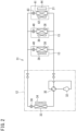
- FIG. 1 is a diagram illustrating an exemplary configuration of an air conditioning system according to an embodiment of the present disclosure.
- the air conditioning system 10 adjusts a temperature and a humidity inside a room R (i.e., a target space S).
- the air conditioning system 10 includes an air conditioner 11 and an outside air processor 21.
- the air conditioner 11 includes an outdoor unit 12 installed outside the room R, and an indoor unit 13 installed inside the room R. In this embodiment, the indoor unit 13 is installed on a ceiling R1 or in an attic.
- the outside air processor 21 is installed in the attic of the room R.
- the outside air processor 21 is connected to the outside through a duct 21C and is connected to the target space S through a duct 21D.
- the outdoor unit 12 includes a first control device 12A.
- the indoor unit 13 includes a second control device 13A.
- the second control device 13A of the indoor unit 13 is communicably connected to the first control device 12A of the outdoor unit 12, with a communication line.
- a remote controller 13B is connected to the second control device 13A of the indoor unit 13. The remote controller 13B allows a user to operate the air conditioner 11.
- the air conditioner 11 includes one outdoor unit 12 and a plurality of indoor units 13 each connected to the outdoor unit 12.
- Each of the second control devices 13A of the indoor units 13 is communicably connected to the first control device 12A of the outdoor unit 12.
- the first control device 12A of the outdoor unit 12 receives identification codes from the second control devices 13A of the respective indoor units 13, thereby distinguishing the indoor units 13 from one another.
- a plurality of remote controllers 13B may be provided for the respective indoor units 13 or a single remote controller 13B may be provided for the plurality of indoor units 13.
- the outside air processor 21 includes a third control device 21A.
- the third control device 21A of the outside air processor 21 is communicably connected to the first control device 12A of the outdoor unit 12, with a communication line.
- a remote controller 21B is connected to the third control device 21A of the outside air processor 21.
- the remote controller 21B allows the user to operate the outside air processor 21.
- the first control device 12A of the outdoor unit 12 receives an identification code from the third control device 13A of the outside air processor 21, thereby distinguishing the outside air processor 21 from each indoor unit 13.
- Each of the first, second, and third control devices 12A, 13A, and 21A is practicable using a computer including a processor, a memory, and the like.
- Each of the first, second, and third control devices 12A, 13A, and 21A exerts various functions in such a way that the processor executes a control program stored in the memory.
- FIG. 2 is a diagram illustrating an exemplary refrigerant circuit in the air conditioning system 10.
- the outdoor unit 12, the indoor units 13, and the outside air processor 21 are connected to each other with a single-route refrigerant circuit 31.
- the outdoor unit 12 includes, for example, a compressor 32, an outdoor heat exchanger 33, a fan 34, a four-way switching valve 35, and an expansion mechanism 36.
- the compressor 32 causes a refrigerant to circulate through the refrigerant circuit.
- the outdoor heat exchanger 33 causes the refrigerant to exchange heat with air to increase or decrease a temperature of the air.
- the fan 34 generates a flow of air and provides the air to the outdoor heat exchanger 33.
- the four-way switching valve 35 switches between a way to cause the refrigerant discharged from the compressor 32 to flow toward the outdoor heat exchanger 33 and a way to cause the refrigerant to flow toward indoor heat exchangers 38 and 41 which will be described later.
- the expansion mechanism 36 includes, for example, an electric expansion valve and adjusts a flow rate of the refrigerant flowing through the outdoor heat exchanger 33.
- the first control device 12A controls operations of the compressor 32, fan 34, four-way switching valve 35, and expansion mechanism 36.
- Each indoor unit 13 includes, for example, the indoor heat exchanger 38, a fan 39, and an expansion mechanism 40.
- the indoor heat exchanger 38 causes the refrigerant to exchange heat with air to increase or decrease a temperature of the air.
- the fan 39 generates a flow of air and provides the air to the indoor heat exchanger 38.
- the expansion mechanism 40 includes, for example, an electric expansion valve and adjusts a flow rate of the refrigerant flowing through the indoor heat exchanger 38.
- the second control device 13A controls operations of the fan 39 and expansion mechanism 40.
- the outside air processor 21 includes, for example, the indoor heat exchanger 41, a fan 42, an expansion mechanism 43, and a humidifier 44.
- the indoor heat exchanger 41 causes the refrigerant to exchange heat with air to increase or decrease a temperature of the air.
- the fan 42 generates a flow of air and provides the air to each of the indoor heat exchanger 41 and the humidifier 44.
- the expansion mechanism 43 includes, for example, an electric expansion valve and adjusts a flow rate of the refrigerant flowing through the indoor heat exchanger 41.
- the humidifier 44 includes, for example, an element capable of retaining moisture, and humidifies air that passes through the element.
- the third control device 21A controls operations of the fan 42 and expansion mechanism 43.
- the outdoor unit 12, the indoor units 13, and the outside air processors 21 are each capable of performing a known vapor compression refrigeration cycle operation, thereby conditioning the air in the target space S.
- each indoor unit 13 performs air conditioning by taking in the air in the target space S, causing the indoor heat exchanger 38 to adjust the temperature of the air, and blowing out the air into the target space S.
- an output of each indoor unit 13 refers to a capability of the indoor unit 13 to increase or decrease the temperature of the air in the target space S.
- the outside air processor 21 performs air conditioning by taking in outside air, adjusting a temperature and a humidity of the outside air, and blowing out the outside air into the target space S.
- the outside air processor 21 specifically, the fan 42 takes in outside air, the indoor heat exchanger 41 adjusts a temperature of the outside air, and the humidifier 44 adjusts a humidity of the outside air.
- an output of the outside air processor 21 refers to a capability of the outside air processor 21 to increase or decrease the temperature and humidity of the air in the target space S.
- the outside air processor 21 may alternatively be configured to adjust one of a temperature and a humidity of the target space S.
- the second control device 13A performs ordinary operation control and output restriction control under which the output is restricted as compared with the output under the ordinary operation control.
- the ordinary operation control is control to adjust an opening degree of the expansion mechanism 40 and a number of rotations of the fan 39, thereby adjusting the temperature of the target space S to a predetermined target temperature.
- the output restriction control includes suppression control to suppress the output and control to stop the operation (stop control).
- the suppression control may be, for example, control to close the expansion mechanism 40 while driving the fan 39, thereby stopping a flow of the refrigerant to the indoor heat exchanger 38.
- the stop control may be control to close the expansion mechanism 40 and stop the fan 39 when the user stops the operation with the remote controller 13B.
- the third control device 21A performs ordinary operation control and output restriction control under which the output is restricted as compared with the output under the ordinary operation control.
- the ordinary operation control is control to adjust an opening degree of the expansion mechanism 43 and a number of rotations of the fan 42, thereby adjusting the temperature and humidity of the target space S to predetermined target values.
- the output restriction control includes suppression control to suppress the output and control to stop the operation (stop control).
- the suppression control may be, for example, control to close the expansion mechanism 43 while driving the fan 42, thereby stopping a flow of the refrigerant to the indoor heat exchanger 41.
- the stop control may be control to close the expansion mechanism 43 and stop the fan 42 when the user stops the operation with the remote controller 21B.
- the first control device 12A of the outdoor unit 12 communicates with the second control device 13A of each indoor unit 13 and the third control device 21A of the outside air processor 21 to receive control states from the second control device 13A and third control device 21A. Therefore, the first control device 12A of the outdoor unit 12 is capable of recognizing a present state of each of the indoor unit 13 and the outside air processor 21 performing the ordinary operation control or the output restriction control.
- the first control device 12A of the outdoor unit 12 performs "association control" to cause the outside air processor 21 to shift to the output restriction control in association with a shift of each indoor unit 13 to the output restriction control.
- association control a specific description will be given of the "association control”.
- FIG. 3 is a table illustrating a correspondence relationship between the output restriction control by each indoor unit 13 and the output restriction control by the outside air processor 21 under the association control.
- This table shows a correspondence between a state of each indoor unit 13 performing the output restriction control and a state of the outside air processor 21 performing the output restriction control, the outside air processor 21 being shifted to this state by the first control device 12A of the outdoor unit 12.
- the first control device 12A of the outdoor unit 12 performs control to cause the outside air processor 21 to shift to one of states (A) to (D) in FIG. 3 .
- the state (A) indicates that when all the indoor units 13 shift to the output restriction control and at least one of the indoor units 13 shifts to the suppression control, in other words, when all the indoor units 13 shift to the suppression control or when some of the indoor units 13 shift to the suppression control while some of the indoor units 13 shift to the stop control, the first control device 12A of the outdoor unit 12 performs control to cause the outside air processor 21 to shift to the suppression control.
- the state (B) indicates that when all the indoor units 13 shift to the stop control, the first control device 12A of the outdoor unit 12 performs control to cause the outside air processor 21 to shift to the suppression control.
- the state (C) indicates that when one of the indoor units 13 in the state (A) shifts to the ordinary operation control, the first control device 12A of the outdoor unit 12 performs control to cause the outside air processor 21 to shift from the suppression control to the ordinary operation control.
- the state (D) indicates that when one of the indoor units 13 in the state (B) shifts to the ordinary operation control, the first control device 12A of the outdoor unit 12 performs control to cause the outside air processor 21 to shift from the suppression control to the ordinary operation control.
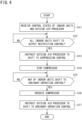
- FIG. 4 is a flowchart illustrating an exemplary processing procedure in the first control device 12A of the outdoor unit 12 from a shift of each indoor unit 13 to the output restriction control to a return to the ordinary operation control.
- the first control device 12A of the outdoor unit 12 receives control states of the indoor units 13 from the second control devices 13A and receives a control state of the outside air processor 21 from the third control device 21A.
- step S 12 the first control device 12A determines whether all the indoor units 13 shift to the output restriction control, in other words, whether all the indoor units 13 shift to the suppression control (the state (A) in FIG. 3 ) or the stop control (the state (B) in FIG. 3 ).
- the first control device 12A makes a positive determination (YES) in step S12, then, in step S 13, the first control device 12A transmits a signal instructing a shift to the suppression control to the third control device 21A of the outside air processor 21.
- the third control device 21A of the outside air processor 21 performs the suppression control, based on the instruction signal from the first control device 12A.
- step S14 next, the first control device 12Aperforms control to stop the compressor 32 of the outdoor unit 12. Since all the indoor units 13 shift to the suppression control or the stop control and the outside air processor 21 shifts to the suppression control before the processing proceeds to step S13, no problem occurs even when the compressor 32 is stopped. Stopping the compressor 32 enables a reduction in operating time and a reduction in power consumption.
- the shift of the outside air processor 21 to the suppression control may alternatively be achieved when the first control device 12A performs control to stop the compressor 32. For example, when the compressor 32 is stopped, the refrigerant does not flow into the indoor heat exchanger 41 of the outside air processor 21; therefore, the outside air processor 21 substantially shifts to the suppression control.
- step S15 when the first control device 12A of the outdoor unit 12 receives a signal indicating a shift to the ordinary operation control from the second control device 13A of any of the indoor units 13, then, in step S16, the first control device 12A of the outdoor unit 12 restarts the operation of the compressor 32.
- step S17 the first control device 12A transmits a signal instructing a shift to the ordinary operation control to the third control device 21A of the outside air processor 21.
- the third control device 21A of the outside air processor 21 performs the ordinary operation control, based on the instruction signal from the first control device 12A.
- the first control device 12A of the outdoor unit 12 is thus capable of causing the outside air processor 21 to shift to the output restriction control in association with the output restriction control by the indoor units 13.
- This configuration thus eliminates continuation of an unnecessary operation of the outside air processor 21 while the indoor units 13 perform the suppression control or stop, and therefore enables a reduction in power consumption owing to the wasteful operation of the outside air processor 21.
- FIG. 5 is a table illustrating a correspondence relationship between the output restriction control by each indoor unit 13 and the output restriction control by the outside air processor 21 under the association control according to a modification.
- the first control device 12A of the outdoor unit 12 performs control to cause the outside air processor 21 to shift to one of states (E) to (H) in FIG. 5 .
- the state (E) indicates that when all the indoor units 13 shift to the output restriction control and at least one of the indoor units 13 shifts to the suppression control, in other words, when all the indoor units 13 shift to the suppression control or when some of the indoor units 13 shift to the suppression control while some of the indoor units 13 shift to the stop control, the first control device 12A of the outdoor unit 12 performs control to cause the outside air processor 21 to shift to the suppression control.
- the state (F) indicates that when all the indoor units 13 shift to the stop control, the first control device 12A of the outdoor unit 12 performs control to cause the outside air processor 21 to shift to the stop control.
- the state (G) indicates that when one of the indoor units 13 in the control state (E) shifts to the ordinary operation control, the first control device 12A of the outdoor unit 12 performs control to cause the outside air processor 21 to shift from the suppression control to the ordinary operation control.
- the state (H) indicates that when one of the indoor units 13 in the control state (F) shifts to the ordinary operation control, the outdoor unit 12 is maintained in a stopped state.
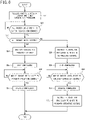
- FIG. 6 is a flowchart illustrating an exemplary processing procedure in the first control device 12A of the outdoor unit 12 from a shift of each indoor unit 13 to the output restriction control to a return to the ordinary operation control.
- the first control device 12A of the outdoor unit 12 receives control states of the indoor units 13 from the second control devices 13A and receives a control state of the outside air processor 21 from the third control device 21A.
- step S22 the first control device 12A determines whether all the indoor units 13 shift to the output restriction control.
- the first control device 12A makes a positive determination (YES) in step S22
- step S23 the first control device 12A determines whether all the indoor units 13 shift to the stop control.
- a positive determination (YES) in step S23 made by the first control device 12A indicates that all the indoor units 13 shift to the stop control (the state (F) in FIG. 5 ).
- a negative determination (NO) made by the first control device 12A indicates that all the indoor units 13 shift to the output restriction control and at least one of the indoor units 13 shifts to the suppression control (the state (E) in FIG. 5 ).
- step S24 the first control device 12A of the outdoor unit 12 transmits a signal instructing a shift to the stop control to the third control device 21A of the outside air processor 21.
- the third control device 21A of the outside air processor 21 performs the stop control, based on the instruction signal from the first control device 12A.
- step S25 the first control device 12A of the outdoor unit 12 performs control to stop the compressor 32 of the outdoor unit 12. Since all the indoor units 13 and the outside air processor 21 shift to the stop control before the processing proceeds to step S23, no problem occurs even when the compressor 32 is stopped. This configuration thus reduces an operating time of the compressor 32, leading to a reduction in power consumption.
- step S26 when the first control device 12A of the outdoor unit 12 receives a signal indicating a shift to the ordinary operation control from the second control device 13A of any of the indoor units 13, then, in step S27, the first control device 12A of the outdoor unit 12 restarts the operation of the compressor 32.
- the first control device 12A maintains the outside air processor 21 in the stopped state without transmitting a signal instructing a shift to the ordinary operation control to the third control device 21A of the outside air processor 21.
- step S28 the first control device 12A of the outdoor unit 12 transmits a signal instructing a shift to the suppression control to the third control device 21A of the outside air processor 21.
- the third control device 21A of the outside air processor 21 performs the suppression control, based on the instruction signal from the first control device 12A.
- step S29 next, the first control device 12A performs control to stop the compressor 32 of the outdoor unit 12. Since all the indoor units 13 shift to the suppression control or the stop control and the outside air processor 21 shifts to the suppression control before the processing proceeds to step S28, no problem occurs even when the compressor 32 is stopped. This configuration thus reduces an operating time of the compressor 32, leading to a reduction in power consumption.
- the shift of the outside air processor 21 to the suppression control may alternatively be achieved when the first control device 12A performs control to stop the compressor 32.
- step S30 when the first control device 12A of the outdoor unit 12 receives a signal indicating a shift to the ordinary operation control from the second control device 13A of any of the indoor units 13, then, in step S31, the first control device 12A of the outdoor unit 12 restarts the operation of the compressor 32.
- the first control device 12A transmits a signal instructing a shift to the ordinary operation control to the third control device 21A of the outside air processor 21.
- the third control device 21A of the outside air processor 21 performs the ordinary operation control, based on the instruction signal from the first control device 12A.
- the first control device 12A of the outdoor unit 12 is thus capable of causing the outside air processor 21 to shift to the output restriction control in association with the output restriction control by the indoor units 13.
- This configuration thus eliminates continuation of an unnecessary operation of the outside air processor 21 while the indoor units 13 perform the suppression control or stop, and therefore enables a reduction in power consumption owing to the wasteful operation of the outside air processor 21.
- the first control device 12A of the outdoor unit 12 may receive selection of one of the way of the association control illustrated in FIGs. 3 and 4 and the way of the association control illustrated in FIGs. 5 and 6 and perform the association control in the selected way.
- a control board on which the computer of the first control device 12A is mounted is provided with a selector, such as a DIP switch, for selecting the way of the association control.
- the way of the association control can be selected through settings by a service engineer.
- the air conditioning system 10 includes the plurality of indoor units 13.
- the air conditioning system 10 may alternatively include one indoor unit 13.
- the air conditioning system 10 includes one outside air processor 21.
- the air conditioning system 10 may alternatively include a plurality of outside air processors 21.
- the air conditioning system 10 includes one outdoor unit 12.
- the air conditioning system 10 may alternatively include a plurality of outdoor units 12. In this case, the association control can be performed by the first control device 12A of one outdoor unit (master) 12 of the plurality of outdoor units 12.
- the suppression control by each of the indoor units 13 and the suppression control by the outside air processor 21 described in the foregoing embodiment may alternatively be control to make the number of rotations of each of the fans 39 and 42 equal to that under the ordinary operation control and make the opening degree of each of the expansion mechanisms 40 and 43 smaller than that under the ordinary operation control.
- the suppression control may be control to decrease the number of rotations of each of the fans 39 and 42 so as to be smaller than that under the ordinary operation control, in order to achieve power saving by a reduction in amount of heat to be exchanged by each of the indoor heat exchangers 38 and 41.
- the compressor 32 is not necessarily stopped in step S14 of FIG. 4 and in step S29 of FIG. 6 .
Landscapes
- Engineering & Computer Science (AREA)
- Chemical & Material Sciences (AREA)
- Combustion & Propulsion (AREA)
- Mechanical Engineering (AREA)
- General Engineering & Computer Science (AREA)
- Signal Processing (AREA)
- Physics & Mathematics (AREA)
- Fuzzy Systems (AREA)
- Mathematical Physics (AREA)
- Thermal Sciences (AREA)
- Human Computer Interaction (AREA)
- Air Conditioning Control Device (AREA)
Abstract
Description
- The present disclosure relates to an air conditioning system.
- Patent Literature 1 discloses an air conditioning system including an air conditioner and an outside air processor. The air conditioner includes an outdoor unit and an indoor unit that are connected to each other with a refrigerant circuit. The indoor unit takes in air in a room, adjusts a temperature of the air, and blows out the air into the room. The outside air processor takes in air outside the room, adjusts a temperature and a humidity of the air, and blows out the air into the room.
- PATENT LITERATURE 1:
Japanese Laid-Open Patent Publication No. 2010-121912 - The outside air processor is typically installed in, for example, an attic which is an inconspicuous place, and is connected to a blow-out port formed in, for example, a ceiling, through a duct. Therefore, some users do not know the presence of the outside air processor and therefore stop only the operation of the air conditioning apparatus while keeping the outside air processor operating even after the use of the room, which may result in wasteful power consumption.
- An object of the present disclosure is to reduce power consumption by an operation of an outside air processor.
-
- (1) An air conditioning system according to the present disclosure includes: an outdoor unit including a control device; an indoor unit communicably connected to the control device; and an outside air processor communicably connected to the control device.
- In the air conditioning system, the indoor unit is capable of performing ordinary operation control to adjust a temperature of air in a room, the air being taken in the indoor unit, and supply the air into the room, and output restriction control under which an output is restricted as compared with an output under the ordinary operation control.
- The outside air processor is capable of performing ordinary operation control to adjust at least one of a temperature and a humidity of air outside the room, the air being taken in the outside air processor, and supply the air into the room, and output restriction control under which an output is restricted as compared with an output under the ordinary operation control.
- The control device causes the outside air processor to shift from the ordinary operation control to the output restriction control on condition that the indoor unit shifts from the ordinary operation control to the output restriction control.
- The air conditioning system having the configuration described above is capable of restricting the output of the outside air processor in association with the restriction to the output of the indoor unit. The air conditioning system is therefore capable of reducing power consumption owing to an operation of the outside air processor.
- (2) The air conditioning system as recited in (1) preferably includes a plurality of the indoor units.
- In the air conditioning system, preferably, the control device causes the outside air processor to shift to the output restriction control on condition that all the indoor units shift to the output restriction control.
- In a case where the air conditioning system includes the plurality of indoor units, the air conditioning system is capable of suppressing the output of the outside air processor in association with the shift of all of the plurality of the indoor units to the output restriction control.
- (3) In the air conditioning system as recited in (2), preferably,
- the output restriction control by each of the indoor units and the output restriction control by the outside air processor each include stop control to stop the output, and
- the control device causes the outside air processor to shift to the stop control on condition that all the indoor units shift to the stop control.
- With this configuration, for example, when a user finishes using the room, the air conditioning system is capable of stopping the outside air processor in association with the stop of the indoor units.
- (4) In the air conditioning system as recited in (2), preferably,
- the output restriction control by each of the indoor units includes stop control to stop the output,
- the output restriction control by the outside air processor includes suppression control to suppress the output, and
- the control device causes the outside air processor to shift to the suppression control on condition that all the indoor units shift to the stop control.
- In this case, the air conditioning system is capable of suppressing the output of the outside air processor in association with the suppression of the outputs of all the indoor units under the stop control.
- (5) In the air conditioning system as recited in any of (2) to (4), preferably,
- the output restriction control by each of the indoor units includes stop control to stop the output and suppression control to suppress the output,
- the output restriction control by the outside air processor includes suppression control to suppress the output, and
- the control device causes the outside air processor to shift to the suppression control on condition that all the indoor units shift to the output restriction control and at least one of the indoor units shifts to the suppression control.
- In this case, the air conditioning system is capable of suppressing the output of the outside air processor in association with the suppression of the outputs of all the indoor units under the suppression control or the stop control.
- (6) In the air conditioning system as recited in (3), preferably,
the outside air processor is maintained at the stop control on condition that the outside air processor shifts to the stop control in association with a shift of all the indoor units to the stop control, and then at least one of the indoor units shifts to the ordinary operation control. - With this configuration, even when any of the indoor units shifts from the stop control to the ordinary operation control, the air conditioning system is capable of suppressing an unnecessary operation of the outside air processor, by maintaining the outside air processor at the stop control regardless of the shift.
- (7) In the air conditioning system as recited in (4), preferably,
the control device causes the outside air processor to shift to the ordinary operation control on condition that the outside air processor shifts to the suppression control in association with a shift of all the indoor units to the stop control, and then any of the indoor units shifts to the ordinary operation control. - (8) In the air conditioning system as recited in (5), preferably,
the control device causes the outside air processor to shift to the ordinary operation control on condition that the outside air processor shifts to the suppression control in association with a shift of all the indoor units to the output restriction control, and then any of the indoor units shifts to the ordinary operation control. - (9) In the air conditioning system as recited in (4), (5), (7), or (8), preferably,
- the outdoor unit includes a compressor,
- the outdoor unit, the indoor units, and the outside air processor are connected to each other with a refrigerant circuit through which a refrigerant circulates by the compressor, and
- the suppression control by the outside air processor involves a stop of the compressor.
- With this configuration, the air conditioning system is capable of causing the outside air processor to perform the suppression control, by stopping the compressor of the outdoor unit.
-
-
FIG. 1 is a diagram illustrating an exemplary configuration of an air conditioning system according to an embodiment of the present disclosure. -
FIG. 2 is a diagram illustrating an exemplary refrigerant circuit in the air conditioning system. -
FIG. 3 is a table illustrating a correspondence relationship between output restriction control by an indoor unit and output restriction control by an outside air processor under association control. -
FIG. 4 is a flowchart illustrating an exemplary processing procedure in a first control device of an outdoor unit from a shift of the indoor unit to the output restriction control to a return to ordinary operation control. -
FIG. 5 is a table illustrating a correspondence relationship between the output restriction control by the indoor unit and the output restriction control by the outside air processor under the association control according to a modification. -
FIG. 6 is a flowchart illustrating an exemplary processing procedure in the first control device of the outdoor unit from a shift of the indoor unit to the output restriction control to a return to the ordinary operation control. -
FIG. 1 is a diagram illustrating an exemplary configuration of an air conditioning system according to an embodiment of the present disclosure. Theair conditioning system 10 adjusts a temperature and a humidity inside a room R (i.e., a target space S). Theair conditioning system 10 includes anair conditioner 11 and anoutside air processor 21. Theair conditioner 11 includes anoutdoor unit 12 installed outside the room R, and anindoor unit 13 installed inside the room R. In this embodiment, theindoor unit 13 is installed on a ceiling R1 or in an attic. Theoutside air processor 21 is installed in the attic of the room R. Theoutside air processor 21 is connected to the outside through aduct 21C and is connected to the target space S through aduct 21D. - The
outdoor unit 12 includes afirst control device 12A. Theindoor unit 13 includes asecond control device 13A. Thesecond control device 13A of theindoor unit 13 is communicably connected to thefirst control device 12A of theoutdoor unit 12, with a communication line. Aremote controller 13B is connected to thesecond control device 13A of theindoor unit 13. Theremote controller 13B allows a user to operate theair conditioner 11. - In this embodiment, the
air conditioner 11 includes oneoutdoor unit 12 and a plurality ofindoor units 13 each connected to theoutdoor unit 12. Each of thesecond control devices 13A of theindoor units 13 is communicably connected to thefirst control device 12A of theoutdoor unit 12. Thefirst control device 12A of theoutdoor unit 12 receives identification codes from thesecond control devices 13A of the respectiveindoor units 13, thereby distinguishing theindoor units 13 from one another. A plurality ofremote controllers 13B may be provided for the respectiveindoor units 13 or a singleremote controller 13B may be provided for the plurality ofindoor units 13. - The
outside air processor 21 includes athird control device 21A. Thethird control device 21A of theoutside air processor 21 is communicably connected to thefirst control device 12A of theoutdoor unit 12, with a communication line. Aremote controller 21B is connected to thethird control device 21A of theoutside air processor 21. Theremote controller 21B allows the user to operate theoutside air processor 21. Thefirst control device 12A of theoutdoor unit 12 receives an identification code from thethird control device 13A of theoutside air processor 21, thereby distinguishing theoutside air processor 21 from eachindoor unit 13. - Each of the first, second, and
third control devices third control devices -
FIG. 2 is a diagram illustrating an exemplary refrigerant circuit in theair conditioning system 10. - The
outdoor unit 12, theindoor units 13, and theoutside air processor 21 are connected to each other with a single-route refrigerant circuit 31. Theoutdoor unit 12 includes, for example, acompressor 32, anoutdoor heat exchanger 33, afan 34, a four-way switching valve 35, and anexpansion mechanism 36. Thecompressor 32 causes a refrigerant to circulate through the refrigerant circuit. Theoutdoor heat exchanger 33 causes the refrigerant to exchange heat with air to increase or decrease a temperature of the air. Thefan 34 generates a flow of air and provides the air to theoutdoor heat exchanger 33. The four-way switching valve 35 switches between a way to cause the refrigerant discharged from thecompressor 32 to flow toward theoutdoor heat exchanger 33 and a way to cause the refrigerant to flow towardindoor heat exchangers expansion mechanism 36 includes, for example, an electric expansion valve and adjusts a flow rate of the refrigerant flowing through theoutdoor heat exchanger 33. In theoutdoor unit 12, thefirst control device 12A(seeFIG. 1 ) controls operations of thecompressor 32,fan 34, four-way switching valve 35, andexpansion mechanism 36. - Each
indoor unit 13 includes, for example, theindoor heat exchanger 38, afan 39, and anexpansion mechanism 40. Theindoor heat exchanger 38 causes the refrigerant to exchange heat with air to increase or decrease a temperature of the air. Thefan 39 generates a flow of air and provides the air to theindoor heat exchanger 38. Theexpansion mechanism 40 includes, for example, an electric expansion valve and adjusts a flow rate of the refrigerant flowing through theindoor heat exchanger 38. In theindoor unit 13, thesecond control device 13A (seeFIG. 1 ) controls operations of thefan 39 andexpansion mechanism 40. - The
outside air processor 21 includes, for example, theindoor heat exchanger 41, afan 42, anexpansion mechanism 43, and ahumidifier 44. Theindoor heat exchanger 41 causes the refrigerant to exchange heat with air to increase or decrease a temperature of the air. Thefan 42 generates a flow of air and provides the air to each of theindoor heat exchanger 41 and thehumidifier 44. Theexpansion mechanism 43 includes, for example, an electric expansion valve and adjusts a flow rate of the refrigerant flowing through theindoor heat exchanger 41. Thehumidifier 44 includes, for example, an element capable of retaining moisture, and humidifies air that passes through the element. In theoutside air processor 21, thethird control device 21A controls operations of thefan 42 andexpansion mechanism 43. - The
outdoor unit 12, theindoor units 13, and theoutside air processors 21 are each capable of performing a known vapor compression refrigeration cycle operation, thereby conditioning the air in the target space S. According to this refrigeration cycle operation, eachindoor unit 13 performs air conditioning by taking in the air in the target space S, causing theindoor heat exchanger 38 to adjust the temperature of the air, and blowing out the air into the target space S. In this description, an output of eachindoor unit 13 refers to a capability of theindoor unit 13 to increase or decrease the temperature of the air in the target space S. - The
outside air processor 21 performs air conditioning by taking in outside air, adjusting a temperature and a humidity of the outside air, and blowing out the outside air into the target space S. In theoutside air processor 21, specifically, thefan 42 takes in outside air, theindoor heat exchanger 41 adjusts a temperature of the outside air, and thehumidifier 44 adjusts a humidity of the outside air. In this description, an output of theoutside air processor 21 refers to a capability of theoutside air processor 21 to increase or decrease the temperature and humidity of the air in the target space S. Theoutside air processor 21 may alternatively be configured to adjust one of a temperature and a humidity of the target space S. - In each
indoor unit 13, thesecond control device 13A performs ordinary operation control and output restriction control under which the output is restricted as compared with the output under the ordinary operation control. The ordinary operation control is control to adjust an opening degree of theexpansion mechanism 40 and a number of rotations of thefan 39, thereby adjusting the temperature of the target space S to a predetermined target temperature. The output restriction control includes suppression control to suppress the output and control to stop the operation (stop control). The suppression control may be, for example, control to close theexpansion mechanism 40 while driving thefan 39, thereby stopping a flow of the refrigerant to theindoor heat exchanger 38. The stop control may be control to close theexpansion mechanism 40 and stop thefan 39 when the user stops the operation with theremote controller 13B. - Also in the
outside air processor 21, thethird control device 21A performs ordinary operation control and output restriction control under which the output is restricted as compared with the output under the ordinary operation control. The ordinary operation control is control to adjust an opening degree of theexpansion mechanism 43 and a number of rotations of thefan 42, thereby adjusting the temperature and humidity of the target space S to predetermined target values. The output restriction control includes suppression control to suppress the output and control to stop the operation (stop control). The suppression control may be, for example, control to close theexpansion mechanism 43 while driving thefan 42, thereby stopping a flow of the refrigerant to theindoor heat exchanger 41. The stop control may be control to close theexpansion mechanism 43 and stop thefan 42 when the user stops the operation with theremote controller 21B. - The
first control device 12A of theoutdoor unit 12 communicates with thesecond control device 13A of eachindoor unit 13 and thethird control device 21A of theoutside air processor 21 to receive control states from thesecond control device 13A andthird control device 21A. Therefore, thefirst control device 12A of theoutdoor unit 12 is capable of recognizing a present state of each of theindoor unit 13 and theoutside air processor 21 performing the ordinary operation control or the output restriction control. - According to this embodiment, the
first control device 12A of theoutdoor unit 12 performs "association control" to cause theoutside air processor 21 to shift to the output restriction control in association with a shift of eachindoor unit 13 to the output restriction control. Next, a specific description will be given of the "association control". -
FIG. 3 is a table illustrating a correspondence relationship between the output restriction control by eachindoor unit 13 and the output restriction control by theoutside air processor 21 under the association control. This table shows a correspondence between a state of eachindoor unit 13 performing the output restriction control and a state of theoutside air processor 21 performing the output restriction control, theoutside air processor 21 being shifted to this state by thefirst control device 12A of theoutdoor unit 12. Thefirst control device 12A of theoutdoor unit 12 performs control to cause theoutside air processor 21 to shift to one of states (A) to (D) inFIG. 3 . - In
FIG. 3 , the state (A) indicates that when all theindoor units 13 shift to the output restriction control and at least one of theindoor units 13 shifts to the suppression control, in other words, when all theindoor units 13 shift to the suppression control or when some of theindoor units 13 shift to the suppression control while some of theindoor units 13 shift to the stop control, thefirst control device 12A of theoutdoor unit 12 performs control to cause theoutside air processor 21 to shift to the suppression control. - In
FIG. 3 , the state (B) indicates that when all theindoor units 13 shift to the stop control, thefirst control device 12A of theoutdoor unit 12 performs control to cause theoutside air processor 21 to shift to the suppression control. - In
FIG. 3 , the state (C) indicates that when one of theindoor units 13 in the state (A) shifts to the ordinary operation control, thefirst control device 12A of theoutdoor unit 12 performs control to cause theoutside air processor 21 to shift from the suppression control to the ordinary operation control. - In
FIG. 3 , the state (D) indicates that when one of theindoor units 13 in the state (B) shifts to the ordinary operation control, thefirst control device 12A of theoutdoor unit 12 performs control to cause theoutside air processor 21 to shift from the suppression control to the ordinary operation control. - Next, a description will be given of a specific processing procedure in the
first control device 12A under the association control. -
FIG. 4 is a flowchart illustrating an exemplary processing procedure in thefirst control device 12A of theoutdoor unit 12 from a shift of eachindoor unit 13 to the output restriction control to a return to the ordinary operation control. - As illustrated in
FIG. 4 , in step S11, thefirst control device 12A of theoutdoor unit 12 receives control states of theindoor units 13 from thesecond control devices 13A and receives a control state of theoutside air processor 21 from thethird control device 21A. - In
step S 12, thefirst control device 12A determines whether all theindoor units 13 shift to the output restriction control, in other words, whether all theindoor units 13 shift to the suppression control (the state (A) inFIG. 3 ) or the stop control (the state (B) inFIG. 3 ). When thefirst control device 12A makes a positive determination (YES) in step S12, then, instep S 13, thefirst control device 12A transmits a signal instructing a shift to the suppression control to thethird control device 21A of theoutside air processor 21. Thethird control device 21A of theoutside air processor 21 performs the suppression control, based on the instruction signal from thefirst control device 12A. - In step S14, next, the first control device 12Aperforms control to stop the
compressor 32 of theoutdoor unit 12. Since all theindoor units 13 shift to the suppression control or the stop control and theoutside air processor 21 shifts to the suppression control before the processing proceeds to step S13, no problem occurs even when thecompressor 32 is stopped. Stopping thecompressor 32 enables a reduction in operating time and a reduction in power consumption. The shift of theoutside air processor 21 to the suppression control may alternatively be achieved when thefirst control device 12A performs control to stop thecompressor 32. For example, when thecompressor 32 is stopped, the refrigerant does not flow into theindoor heat exchanger 41 of theoutside air processor 21; therefore, theoutside air processor 21 substantially shifts to the suppression control. - In step S15, when the
first control device 12A of theoutdoor unit 12 receives a signal indicating a shift to the ordinary operation control from thesecond control device 13A of any of theindoor units 13, then, in step S16, thefirst control device 12A of theoutdoor unit 12 restarts the operation of thecompressor 32. Next, in step S17, thefirst control device 12A transmits a signal instructing a shift to the ordinary operation control to thethird control device 21A of theoutside air processor 21. Thethird control device 21A of theoutside air processor 21 performs the ordinary operation control, based on the instruction signal from thefirst control device 12A. - The
first control device 12A of theoutdoor unit 12 is thus capable of causing theoutside air processor 21 to shift to the output restriction control in association with the output restriction control by theindoor units 13. This configuration thus eliminates continuation of an unnecessary operation of theoutside air processor 21 while theindoor units 13 perform the suppression control or stop, and therefore enables a reduction in power consumption owing to the wasteful operation of theoutside air processor 21. -
FIG. 5 is a table illustrating a correspondence relationship between the output restriction control by eachindoor unit 13 and the output restriction control by theoutside air processor 21 under the association control according to a modification. Thefirst control device 12A of theoutdoor unit 12 performs control to cause theoutside air processor 21 to shift to one of states (E) to (H) inFIG. 5 . - In
FIG. 5 , the state (E) indicates that when all theindoor units 13 shift to the output restriction control and at least one of theindoor units 13 shifts to the suppression control, in other words, when all theindoor units 13 shift to the suppression control or when some of theindoor units 13 shift to the suppression control while some of theindoor units 13 shift to the stop control, thefirst control device 12A of theoutdoor unit 12 performs control to cause theoutside air processor 21 to shift to the suppression control. - In
FIG. 5 , the state (F) indicates that when all theindoor units 13 shift to the stop control, thefirst control device 12A of theoutdoor unit 12 performs control to cause theoutside air processor 21 to shift to the stop control. - In
FIG. 5 , the state (G) indicates that when one of theindoor units 13 in the control state (E) shifts to the ordinary operation control, thefirst control device 12A of theoutdoor unit 12 performs control to cause theoutside air processor 21 to shift from the suppression control to the ordinary operation control. - In
FIG. 5 , the state (H) indicates that when one of theindoor units 13 in the control state (F) shifts to the ordinary operation control, theoutdoor unit 12 is maintained in a stopped state. - Next, a description will be given of a specific processing procedure in the
first control device 12A under the association control according to the modification. -
FIG. 6 is a flowchart illustrating an exemplary processing procedure in thefirst control device 12A of theoutdoor unit 12 from a shift of eachindoor unit 13 to the output restriction control to a return to the ordinary operation control. - As illustrated in
FIG. 6 , in step S21, thefirst control device 12A of theoutdoor unit 12 receives control states of theindoor units 13 from thesecond control devices 13A and receives a control state of theoutside air processor 21 from thethird control device 21A. - In step S22, the
first control device 12A determines whether all theindoor units 13 shift to the output restriction control. When thefirst control device 12A makes a positive determination (YES) in step S22, then, in step S23, thefirst control device 12A determines whether all theindoor units 13 shift to the stop control. A positive determination (YES) in step S23 made by thefirst control device 12A indicates that all theindoor units 13 shift to the stop control (the state (F) inFIG. 5 ). A negative determination (NO) made by thefirst control device 12A indicates that all theindoor units 13 shift to the output restriction control and at least one of theindoor units 13 shifts to the suppression control (the state (E) inFIG. 5 ). - When the
first control device 12A of theoutdoor unit 12 makes the positive determination (YES) in step S23, then, in step S24, thefirst control device 12A of theoutdoor unit 12 transmits a signal instructing a shift to the stop control to thethird control device 21A of theoutside air processor 21. Thethird control device 21A of theoutside air processor 21 performs the stop control, based on the instruction signal from thefirst control device 12A. - In step S25, the
first control device 12A of theoutdoor unit 12 performs control to stop thecompressor 32 of theoutdoor unit 12. Since all theindoor units 13 and theoutside air processor 21 shift to the stop control before the processing proceeds to step S23, no problem occurs even when thecompressor 32 is stopped. This configuration thus reduces an operating time of thecompressor 32, leading to a reduction in power consumption. - In step S26, when the
first control device 12A of theoutdoor unit 12 receives a signal indicating a shift to the ordinary operation control from thesecond control device 13A of any of theindoor units 13, then, in step S27, thefirst control device 12A of theoutdoor unit 12 restarts the operation of thecompressor 32. This configuration thus enables the ordinary operation control by any of theindoor units 13. Thereafter, thefirst control device 12A maintains theoutside air processor 21 in the stopped state without transmitting a signal instructing a shift to the ordinary operation control to thethird control device 21A of theoutside air processor 21. - On the other hand, when the
first control device 12A of theoutdoor unit 12 makes the negative determination (NO) in step S23, then, in step S28, thefirst control device 12A of theoutdoor unit 12 transmits a signal instructing a shift to the suppression control to thethird control device 21A of theoutside air processor 21. Thethird control device 21A of theoutside air processor 21 performs the suppression control, based on the instruction signal from thefirst control device 12A. - In step S29, next, the
first control device 12A performs control to stop thecompressor 32 of theoutdoor unit 12. Since all theindoor units 13 shift to the suppression control or the stop control and theoutside air processor 21 shifts to the suppression control before the processing proceeds to step S28, no problem occurs even when thecompressor 32 is stopped. This configuration thus reduces an operating time of thecompressor 32, leading to a reduction in power consumption. The shift of theoutside air processor 21 to the suppression control may alternatively be achieved when thefirst control device 12A performs control to stop thecompressor 32. - In step S30, when the
first control device 12A of theoutdoor unit 12 receives a signal indicating a shift to the ordinary operation control from thesecond control device 13A of any of theindoor units 13, then, in step S31, thefirst control device 12A of theoutdoor unit 12 restarts the operation of thecompressor 32. This configuration thus enables the ordinary operation control by any of theindoor units 13. Next, in step S32, thefirst control device 12A transmits a signal instructing a shift to the ordinary operation control to thethird control device 21A of theoutside air processor 21. Thethird control device 21A of theoutside air processor 21 performs the ordinary operation control, based on the instruction signal from thefirst control device 12A. - Also in the foregoing modification, the
first control device 12A of theoutdoor unit 12 is thus capable of causing theoutside air processor 21 to shift to the output restriction control in association with the output restriction control by theindoor units 13. This configuration thus eliminates continuation of an unnecessary operation of theoutside air processor 21 while theindoor units 13 perform the suppression control or stop, and therefore enables a reduction in power consumption owing to the wasteful operation of theoutside air processor 21. - The
first control device 12A of theoutdoor unit 12 may receive selection of one of the way of the association control illustrated inFIGs. 3 and4 and the way of the association control illustrated inFIGs. 5 and6 and perform the association control in the selected way. In this case, for example, a control board on which the computer of thefirst control device 12A is mounted is provided with a selector, such as a DIP switch, for selecting the way of the association control. In installing theair conditioner 11 and theoutside air processor 21, the way of the association control can be selected through settings by a service engineer. - In the foregoing embodiment, the
air conditioning system 10 includes the plurality ofindoor units 13. Theair conditioning system 10 may alternatively include oneindoor unit 13. In the foregoing embodiment, theair conditioning system 10 includes oneoutside air processor 21. Theair conditioning system 10 may alternatively include a plurality ofoutside air processors 21. In the foregoing embodiment, theair conditioning system 10 includes oneoutdoor unit 12. Theair conditioning system 10 may alternatively include a plurality ofoutdoor units 12. In this case, the association control can be performed by thefirst control device 12A of one outdoor unit (master) 12 of the plurality ofoutdoor units 12. - The suppression control by each of the
indoor units 13 and the suppression control by theoutside air processor 21 described in the foregoing embodiment may alternatively be control to make the number of rotations of each of thefans expansion mechanisms fans indoor heat exchangers compressor 32 is not necessarily stopped in step S14 ofFIG. 4 and in step S29 ofFIG. 6 . -
- (1) According to the foregoing embodiment, an
air conditioning system 10 includes anoutdoor unit 12 including afirst control device 12A, anindoor unit 13 communicably connected to thefirst control device 12A, and anoutside air processor 21 communicably connected to thefirst control device 12A. Theindoor unit 13 is capable of performing ordinary operation control to adjust a temperature of air in a room, the air being taken in theindoor unit 13, and supply the air into the room, and output restriction control under which an output is restricted as compared with an output under the ordinary operation control. Theoutside air processor 21 is capable of performing ordinary operation control to adjust at least one of a temperature and a humidity of air outside the room, the air being taken in theoutside air processor 21, and supply the air into the room, and output restriction control under which an output is restricted as compared with an output under the ordinary operation control. Thefirst control device 12A causes theoutside air processor 21 to shift from the ordinary operation control to the output restriction control on condition that theindoor unit 13 shifts from the ordinary operation control to the output restriction control. Theair conditioning system 10 is therefore capable of restricting the output of theoutside air processor 21 in association with the restriction to the output of theindoor unit 13 occurring, for example, in a case where theindoor unit 13 shifts to suppression control since a temperature of a target space S reaches a predetermined target temperature or in a case where the operation of theindoor unit 13 stops. Theair conditioning system 10 is thus capable of reducing power consumption owing to the operation of theoutside air processor 21.
Theair conditioning system 10 according to the foregoing embodiment does not include a known centralized controller for collectively controlling theoutdoor unit 12, theindoor unit 13, and theoutside air processor 21. However, thefirst control device 12A of theoutdoor unit 12 is capable of recognizing the control state of theindoor unit 13 and the control state of theoutside air processor 21. In addition, thefirst control device 12A instructs theoutside air processor 21 to shift to the output restriction control or the ordinary operation control. Theair conditioning system 10 is thus capable of achieving association control on theindoor unit 13 and theoutside air processor 21. Therefore, even the relatively small-scaleair conditioning system 10 including no centralized controller is capable of collectively controlling a plurality of theindoor units 13 and theoutside air processor 21. - (2) According to the foregoing embodiment, the
air conditioning system 10 includes the plurality ofindoor units 13, and thefirst control device 12A causes theoutside air processor 21 to shift to the output restriction control on condition that all theindoor units 13 shift to the output restriction control. In the case where theair conditioning system 10 includes the plurality ofindoor units 13, theair conditioning system 10 is capable of suppressing the output of theoutside air processor 21 in association with the shift of all theindoor units 13 to the output restriction control. - (3) According to the foregoing embodiment, the output restriction control by each of the
indoor units 13 and the output restriction control by theoutside air processor 21 each include stop control to stop the output. In the example illustrated inFIGs. 5 and6 , thefirst control device 12A causes theoutside air processor 21 to shift to the stop control on condition that all theindoor units 13 shift to the stop control. The user who uses the room R is less likely to notice the presence of theoutside air processor 21 installed in the attic and therefore sometimes stops only theindoor units 13 and forgets to stop theoutside air processor 21 even after the use of the room R. Even in this case, theair conditioning system 10 according to the foregoing embodiment is capable of automatically stopping theoutside air processor 21 in association with the stop of theindoor units 13, and is therefore capable of reducing wasteful power consumption. - (4) According to the foregoing embodiment, the output restriction control by each of the
indoor units 13 includes stop control to stop the output, and the output restriction control by theoutside air processor 21 includes suppression control to suppress the output. In the example illustrated inFIGs. 3 and4 , thefirst control device 12A causes theoutside air processor 21 to shift to the suppression control on condition that all theindoor units 13 shift to the stop control. Theair conditioning system 10 is therefore capable of suppressing the output of theoutside air processor 21 in association with the suppression of outputs of all theindoor units 13 under the stop control. - (5) According to the foregoing embodiment, the output restriction control by each of the
indoor units 13 includes stop control to stop the output and suppression control to suppress the output, and the output restriction control by theoutside air processor 21 includes suppression control to suppress the output. According to the foregoing embodiment, thefirst control device 12A causes theoutside air processor 21 to shift to the suppression control on condition that all theindoor units 13 shift to the output restriction control and at least one of theindoor units 13 shifts to the suppression control. Theair conditioning system 10 is therefore capable of suppressing the output of theoutside air processor 21 in association with the suppression of outputs of all theindoor units 13 under the suppression control or the stop control. - (6) According to the foregoing embodiment, in the example illustrated in
FIGs. 5 and6 , theoutside air processor 21 is maintained at the stop control on condition that theoutside air processor 21 shifts to the stop control in association with a shift of all theindoor units 13 to the stop control, and then at least one of theindoor units 13 shifts to the ordinary operation control. Therefore, even when any of theindoor units 13 shifts from the stop control to the ordinary operation control, theair conditioning system 10 is capable of suppressing an unnecessary operation of theoutside air processor 21, by maintaining theoutside air processor 21 at the stop control regardless of the shift. - (7) According to the foregoing embodiment, in the example illustrated in
FIGs. 3 and4 , thefirst control device 12A causes theoutside air processor 21 to shift to the ordinary operation control on condition that theoutside air processor 21 shifts to the suppression control in association with a shift of all theindoor units 13 to the stop control, and then any of theindoor units 13 shifts to the ordinary operation control. Theair conditioning system 10 is therefore capable of causing theoutside air processor 21 to shift to the ordinary operation control in association with the shift of any of theindoor units 13 to the ordinary operation control, without a user's operation. - (8) According to the foregoing embodiment, the
first control device 12A causes theoutside air processor 21 to shift to the ordinary operation control on condition that theoutside air processor 21 shifts to the suppression control in association with a shift of all theindoor units 13 to the suppression control or a shift of all theindoor units 13 to the stop control and the suppression control, and then any of theindoor units 13 shifts to the ordinary operation control. Theair conditioning system 10 is therefore capable of causing theoutside air processor 21 to shift to the ordinary operation control in association with the shift of any of theindoor units 13 to the ordinary operation control, without a user's operation. - (9) According to the foregoing embodiment, the
outdoor unit 12 includes acompressor 32, and theoutdoor unit 12, theindoor units 13, and theoutside air processor 21 are connected to each other with arefrigerant circuit 31 through which a refrigerant circulates by thecompressor 32. The suppression control by theoutside air processor 21 involves a stop of thecompressor 32. Theair conditioning system 10 is therefore capable of causing theoutside air processor 21 to perform the suppression control, by stopping thecompressor 32 of theoutdoor unit 12. - While various embodiments have been described herein above, it is to be appreciated that various changes in form and detail may be made without departing from the spirit and scope presently or hereafter claimed.
-
- 10 air conditioning system
- 12 outdoor unit
- 12A first control device
- 13 indoor unit
- 21 outside air processor
- 31 refrigerant circuit
- 32 compressor
Claims (9)
- An air conditioning system comprising:an outdoor unit (12) including a control device (12A);an indoor unit (13) communicably connected to the control device (12A); andan outside air processor (21) communicably connected to the control device (12A), whereinthe indoor unit (13) is capable of performingordinary operation control to adjust a temperature of air in a room, the air being taken in the indoor unit (13), and supply the air into the room, andoutput restriction control under which an output is restricted as compared with an output under the ordinary operation control,the outside air processor (21) is capable of performingordinary operation control to adjust at least one of a temperature and a humidity of air outside the room, the air being taken in the outside air processor (21), and supply the air into the room, andoutput restriction control under which an output is restricted as compared with an output under the ordinary operation control, andthe control device (12A) causes the outside air processor (21) to shift from the ordinary operation control to the output restriction control on condition that the indoor unit (13) shifts from the ordinary operation control to the output restriction control.
- The air conditioning system according to claim 1, comprisinga plurality of the indoor units (13),
whereinthe control device (12A) causes the outside air processor (21) to shift to the output restriction control on condition that all the indoor units (13) shift to the output restriction control. - The air conditioning system according to claim 2, whereinthe output restriction control by each of the indoor units (13) and the output restriction control by the outside air processor (21) each include stop control to stop the output, andthe control device (12A) causes the outside air processor (21) to shift to the stop control on condition that all the indoor units (13) shift to the stop control.
- The air conditioning system according to claim 2, whereinthe output restriction control by each of the indoor units (13) includes stop control to stop the output,the output restriction control by the outside air processor (21) includes suppression control to suppress the output, andthe control device (12A) causes the outside air processor (21) to shift to the suppression control on condition that all the indoor units (13) shift to the stop control.
- The air conditioning system according to any one of claims 2 to 4, whereinthe output restriction control by each of the indoor units (13) includes stop control to stop the output and suppression control to suppress the output,the output restriction control by the outside air processor (21) includes suppression control to suppress the output, andthe control device (12A) causes the outside air processor (21) to shift to the suppression control on condition that all the indoor units (13) shift to the output restriction control and at least one of the indoor units (13) shifts to the suppression control.
- The air conditioning system according to claim 3, wherein
the outside air processor (21) is maintained at the stop control on condition that the outside air processor (21) shifts to the stop control in association with a shift of all the indoor units (13) to the stop control, and then at least one of the indoor units (13) shifts to the ordinary operation control. - The air conditioning system according to claim 4, wherein
the control device (12A) causes the outside air processor (21) to shift to the ordinary operation control on condition that the outside air processor (21) shifts to the suppression control in association with a shift of all the indoor units (13) to the stop control, and then any of the indoor units (13) shifts to the ordinary operation control. - The air conditioning system according to claim 5, wherein
the control device (12A) causes the outside air processor (21) to shift to the ordinary operation control on condition that the outside air processor (21) shifts to the suppression control in association with a shift of all the indoor units (13) to the output restriction control, and then any of the indoor units (13) shifts to the ordinary operation control. - The air conditioning system according to claim 4, 5, 7, or 8, whereinthe outdoor unit (12) includes a compressor (32),the outdoor unit (12), the indoor units (13), and the outside air processor (21) are connected to each other with a refrigerant circuit (31) through which a refrigerant circulates by the compressor (32), andthe suppression control by the outside air processor (21) involves a stop of the compressor (32).
Applications Claiming Priority (2)
| Application Number | Priority Date | Filing Date | Title |
|---|---|---|---|
| JP2020066857A JP6997396B2 (en) | 2020-04-02 | 2020-04-02 | Air conditioning system |
| PCT/JP2021/011091 WO2021200221A1 (en) | 2020-04-02 | 2021-03-18 | Air conditioning system |
Publications (3)
| Publication Number | Publication Date |
|---|---|
| EP4130593A1 true EP4130593A1 (en) | 2023-02-08 |
| EP4130593A4 EP4130593A4 (en) | 2023-09-06 |
| EP4130593B1 EP4130593B1 (en) | 2024-10-09 |
Family
ID=77927941
Family Applications (1)
| Application Number | Title | Priority Date | Filing Date |
|---|---|---|---|
| EP21781714.7A Active EP4130593B1 (en) | 2020-04-02 | 2021-03-18 | Air conditioning system |
Country Status (6)
| Country | Link |
|---|---|
| US (1) | US12331948B2 (en) |
| EP (1) | EP4130593B1 (en) |
| JP (1) | JP6997396B2 (en) |
| CN (1) | CN115362336B (en) |
| ES (1) | ES2998761T3 (en) |
| WO (1) | WO2021200221A1 (en) |
Family Cites Families (16)
| Publication number | Priority date | Publication date | Assignee | Title |
|---|---|---|---|---|
| JP2674359B2 (en) * | 1991-06-14 | 1997-11-12 | ダイキン工業株式会社 | Air conditioner |
| JP2674361B2 (en) * | 1991-06-18 | 1997-11-12 | ダイキン工業株式会社 | Air conditioner |
| JPH07318150A (en) * | 1994-05-20 | 1995-12-08 | Daikin Ind Ltd | Air conditioning system and heat exchange ventilator used therefor |
| JPH08178396A (en) * | 1994-12-28 | 1996-07-12 | Daikin Ind Ltd | Air conditioner |
| JP3074595B2 (en) * | 1995-08-02 | 2000-08-07 | 株式会社山武 | Hotel air conditioning control system |
| JP5487600B2 (en) | 2008-11-21 | 2014-05-07 | ダイキン工業株式会社 | Air conditioning system |
| JP5772157B2 (en) | 2011-04-04 | 2015-09-02 | ダイキン工業株式会社 | Air conditioning system |
| JP5532153B1 (en) * | 2013-01-10 | 2014-06-25 | ダイキン工業株式会社 | Air conditioning system |
| EP3067635B1 (en) * | 2013-11-08 | 2019-12-25 | Mitsubishi Electric Corporation | Air conditioning device |
| CN105473946B (en) * | 2014-07-28 | 2018-04-06 | 江森自控日立空调技术(香港)有限公司 | Air conditioning apparatus |
| JP6419497B2 (en) | 2014-09-12 | 2018-11-07 | 株式会社東芝 | Air conditioning control device, air conditioning control method, and program |
| JP5910719B1 (en) * | 2014-12-15 | 2016-04-27 | ダイキン工業株式会社 | Air conditioner |
| JP6414354B1 (en) * | 2017-03-31 | 2018-10-31 | ダイキン工業株式会社 | Air conditioning system |
| JP6477773B2 (en) * | 2017-04-18 | 2019-03-06 | ダイキン工業株式会社 | Air conditioning system |
| JP6460150B2 (en) | 2017-05-15 | 2019-01-30 | 三菱電機ビルテクノサービス株式会社 | Ventilation system |
| US11221615B2 (en) * | 2018-11-06 | 2022-01-11 | Trane International Inc. | Modifying an environment control setting to facilitate awareness of a fault condition |
-
2020
- 2020-04-02 JP JP2020066857A patent/JP6997396B2/en active Active
-
2021
- 2021-03-18 EP EP21781714.7A patent/EP4130593B1/en active Active
- 2021-03-18 CN CN202180026259.1A patent/CN115362336B/en active Active
- 2021-03-18 ES ES21781714T patent/ES2998761T3/en active Active
- 2021-03-18 WO PCT/JP2021/011091 patent/WO2021200221A1/en not_active Ceased
-
2022
- 2022-08-17 US US17/890,069 patent/US12331948B2/en active Active
Also Published As
| Publication number | Publication date |
|---|---|
| CN115362336A (en) | 2022-11-18 |
| CN115362336B (en) | 2025-12-02 |
| ES2998761T3 (en) | 2025-02-21 |
| JP2021162267A (en) | 2021-10-11 |
| EP4130593A4 (en) | 2023-09-06 |
| JP6997396B2 (en) | 2022-01-17 |
| EP4130593B1 (en) | 2024-10-09 |
| US12331948B2 (en) | 2025-06-17 |
| US20220390136A1 (en) | 2022-12-08 |
| WO2021200221A1 (en) | 2021-10-07 |
Similar Documents
| Publication | Publication Date | Title |
|---|---|---|
| US10989429B2 (en) | Air conditioning system | |
| EP3792565B1 (en) | Air conditioning system | |
| US11402118B2 (en) | Air-conditioning system | |
| EP1980796B1 (en) | Air-conditioning system | |
| KR20110138670A (en) | Air Conditioner and Control Method | |
| JP2021004702A (en) | Outside air treatment device and air conditioning system | |
| US20190353388A1 (en) | Heating, ventilation, and/or air conditioning system with zone control circuitry and master control circuitry | |
| CN1333212C (en) | Air Conditioning System | |
| EP4130593B1 (en) | Air conditioning system | |
| KR20040067980A (en) | Air conditioning apparatus and control method thereof | |
| US20220042702A1 (en) | Air-conditioning system | |
| EP4056914A1 (en) | Air conditioning system | |
| KR20140134872A (en) | An air conditioner and a system thereof | |
| JP4282499B2 (en) | Air conditioner | |
| KR20240113277A (en) | Air conditioner which performs noise suppression control, and method for controlling the same | |
| JP2004333044A (en) | Air conditioning system | |
| JP2025059824A (en) | Air Conditioning System | |
| WO2022210746A1 (en) | Air-conditioning system, control method for air-conditioning system, and control program for air-conditioning system | |
| KR20030031429A (en) | Air Conditioner and Address Switching Method Of The Same | |
| KR100502937B1 (en) | Air conditioner and control method thereof | |
| KR101427273B1 (en) | Power control method of multi air conditioning system | |
| JP2021046998A (en) | Cooling / heating switching type air conditioning system and program | |
| KR20120090274A (en) | Air conditioner and control method thereof | |
| WO2021053748A1 (en) | Outdoor unit, air conditioning system, and program | |
| JPS63302240A (en) | Air conditioner |
Legal Events
| Date | Code | Title | Description |
|---|---|---|---|
| STAA | Information on the status of an ep patent application or granted ep patent |
Free format text: STATUS: THE INTERNATIONAL PUBLICATION HAS BEEN MADE |
|
| PUAI | Public reference made under article 153(3) epc to a published international application that has entered the european phase |
Free format text: ORIGINAL CODE: 0009012 |
|
| STAA | Information on the status of an ep patent application or granted ep patent |
Free format text: STATUS: REQUEST FOR EXAMINATION WAS MADE |
|
| 17P | Request for examination filed |
Effective date: 20220928 |
|
| AK | Designated contracting states |
Kind code of ref document: A1 Designated state(s): AL AT BE BG CH CY CZ DE DK EE ES FI FR GB GR HR HU IE IS IT LI LT LU LV MC MK MT NL NO PL PT RO RS SE SI SK SM TR |
|
| P01 | Opt-out of the competence of the unified patent court (upc) registered |
Effective date: 20230525 |
|
| DAV | Request for validation of the european patent (deleted) | ||
| DAX | Request for extension of the european patent (deleted) | ||
| A4 | Supplementary search report drawn up and despatched |
Effective date: 20230808 |
|
| RIC1 | Information provided on ipc code assigned before grant |
Ipc: F24F 1/0087 20190101ALI20230803BHEP Ipc: F24F 1/0035 20190101ALI20230803BHEP Ipc: F24F 11/86 20180101ALI20230803BHEP Ipc: F24F 11/00 20180101ALI20230803BHEP Ipc: F24F 11/65 20180101ALI20230803BHEP Ipc: F24F 11/54 20180101ALI20230803BHEP Ipc: F24F 11/46 20180101AFI20230803BHEP |
|
| GRAP | Despatch of communication of intention to grant a patent |
Free format text: ORIGINAL CODE: EPIDOSNIGR1 |
|
| STAA | Information on the status of an ep patent application or granted ep patent |
Free format text: STATUS: GRANT OF PATENT IS INTENDED |
|
| RIC1 | Information provided on ipc code assigned before grant |
Ipc: F24F 1/0087 20190101ALI20240415BHEP Ipc: F24F 1/0035 20190101ALI20240415BHEP Ipc: F24F 11/86 20180101ALI20240415BHEP Ipc: F24F 11/00 20180101ALI20240415BHEP Ipc: F24F 11/65 20180101ALI20240415BHEP Ipc: F24F 11/54 20180101ALI20240415BHEP Ipc: F24F 11/46 20180101AFI20240415BHEP |
|
| INTG | Intention to grant announced |
Effective date: 20240508 |
|
| GRAS | Grant fee paid |
Free format text: ORIGINAL CODE: EPIDOSNIGR3 |
|
| GRAA | (expected) grant |
Free format text: ORIGINAL CODE: 0009210 |
|
| STAA | Information on the status of an ep patent application or granted ep patent |
Free format text: STATUS: THE PATENT HAS BEEN GRANTED |
|
| AK | Designated contracting states |
Kind code of ref document: B1 Designated state(s): AL AT BE BG CH CY CZ DE DK EE ES FI FR GB GR HR HU IE IS IT LI LT LU LV MC MK MT NL NO PL PT RO RS SE SI SK SM TR |
|
| REG | Reference to a national code |
Ref country code: CH Ref legal event code: EP |
|
| REG | Reference to a national code |
Ref country code: DE Ref legal event code: R096 Ref document number: 602021020043 Country of ref document: DE |
|
| REG | Reference to a national code |
Ref country code: IE Ref legal event code: FG4D |
|
| REG | Reference to a national code |
Ref country code: LT Ref legal event code: MG9D |
|
| REG | Reference to a national code |
Ref country code: NL Ref legal event code: MP Effective date: 20241009 |
|
| REG | Reference to a national code |
Ref country code: ES Ref legal event code: FG2A Ref document number: 2998761 Country of ref document: ES Kind code of ref document: T3 Effective date: 20250221 |
|
| REG | Reference to a national code |
Ref country code: AT Ref legal event code: MK05 Ref document number: 1730971 Country of ref document: AT Kind code of ref document: T Effective date: 20241009 |
|
| PG25 | Lapsed in a contracting state [announced via postgrant information from national office to epo] |
Ref country code: NL Free format text: LAPSE BECAUSE OF FAILURE TO SUBMIT A TRANSLATION OF THE DESCRIPTION OR TO PAY THE FEE WITHIN THE PRESCRIBED TIME-LIMIT Effective date: 20241009 |
|
| PG25 | Lapsed in a contracting state [announced via postgrant information from national office to epo] |
Ref country code: NL Free format text: LAPSE BECAUSE OF FAILURE TO SUBMIT A TRANSLATION OF THE DESCRIPTION OR TO PAY THE FEE WITHIN THE PRESCRIBED TIME-LIMIT Effective date: 20241009 |
|
| PG25 | Lapsed in a contracting state [announced via postgrant information from national office to epo] |
Ref country code: PT Free format text: LAPSE BECAUSE OF FAILURE TO SUBMIT A TRANSLATION OF THE DESCRIPTION OR TO PAY THE FEE WITHIN THE PRESCRIBED TIME-LIMIT Effective date: 20250210 Ref country code: IS Free format text: LAPSE BECAUSE OF FAILURE TO SUBMIT A TRANSLATION OF THE DESCRIPTION OR TO PAY THE FEE WITHIN THE PRESCRIBED TIME-LIMIT Effective date: 20250209 Ref country code: HR Free format text: LAPSE BECAUSE OF FAILURE TO SUBMIT A TRANSLATION OF THE DESCRIPTION OR TO PAY THE FEE WITHIN THE PRESCRIBED TIME-LIMIT Effective date: 20241009 |
|
| PG25 | Lapsed in a contracting state [announced via postgrant information from national office to epo] |
Ref country code: FI Free format text: LAPSE BECAUSE OF FAILURE TO SUBMIT A TRANSLATION OF THE DESCRIPTION OR TO PAY THE FEE WITHIN THE PRESCRIBED TIME-LIMIT Effective date: 20241009 |
|
| PG25 | Lapsed in a contracting state [announced via postgrant information from national office to epo] |
Ref country code: BG Free format text: LAPSE BECAUSE OF FAILURE TO SUBMIT A TRANSLATION OF THE DESCRIPTION OR TO PAY THE FEE WITHIN THE PRESCRIBED TIME-LIMIT Effective date: 20241009 |
|
| PG25 | Lapsed in a contracting state [announced via postgrant information from national office to epo] |
Ref country code: NO Free format text: LAPSE BECAUSE OF FAILURE TO SUBMIT A TRANSLATION OF THE DESCRIPTION OR TO PAY THE FEE WITHIN THE PRESCRIBED TIME-LIMIT Effective date: 20250109 |
|
| PG25 | Lapsed in a contracting state [announced via postgrant information from national office to epo] |
Ref country code: LV Free format text: LAPSE BECAUSE OF FAILURE TO SUBMIT A TRANSLATION OF THE DESCRIPTION OR TO PAY THE FEE WITHIN THE PRESCRIBED TIME-LIMIT Effective date: 20241009 Ref country code: GR Free format text: LAPSE BECAUSE OF FAILURE TO SUBMIT A TRANSLATION OF THE DESCRIPTION OR TO PAY THE FEE WITHIN THE PRESCRIBED TIME-LIMIT Effective date: 20250110 Ref country code: AT Free format text: LAPSE BECAUSE OF FAILURE TO SUBMIT A TRANSLATION OF THE DESCRIPTION OR TO PAY THE FEE WITHIN THE PRESCRIBED TIME-LIMIT Effective date: 20241009 |
|
| PG25 | Lapsed in a contracting state [announced via postgrant information from national office to epo] |
Ref country code: PL Free format text: LAPSE BECAUSE OF FAILURE TO SUBMIT A TRANSLATION OF THE DESCRIPTION OR TO PAY THE FEE WITHIN THE PRESCRIBED TIME-LIMIT Effective date: 20241009 |
|
| PG25 | Lapsed in a contracting state [announced via postgrant information from national office to epo] |
Ref country code: RS Free format text: LAPSE BECAUSE OF FAILURE TO SUBMIT A TRANSLATION OF THE DESCRIPTION OR TO PAY THE FEE WITHIN THE PRESCRIBED TIME-LIMIT Effective date: 20250109 |
|
| PG25 | Lapsed in a contracting state [announced via postgrant information from national office to epo] |
Ref country code: SM Free format text: LAPSE BECAUSE OF FAILURE TO SUBMIT A TRANSLATION OF THE DESCRIPTION OR TO PAY THE FEE WITHIN THE PRESCRIBED TIME-LIMIT Effective date: 20241009 |
|
| PG25 | Lapsed in a contracting state [announced via postgrant information from national office to epo] |
Ref country code: DK Free format text: LAPSE BECAUSE OF FAILURE TO SUBMIT A TRANSLATION OF THE DESCRIPTION OR TO PAY THE FEE WITHIN THE PRESCRIBED TIME-LIMIT Effective date: 20241009 |
|
| PGFP | Annual fee paid to national office [announced via postgrant information from national office to epo] |
Ref country code: ES Payment date: 20250429 Year of fee payment: 5 |
|
| REG | Reference to a national code |
Ref country code: DE Ref legal event code: R097 Ref document number: 602021020043 Country of ref document: DE |
|
| PG25 | Lapsed in a contracting state [announced via postgrant information from national office to epo] |
Ref country code: EE Free format text: LAPSE BECAUSE OF FAILURE TO SUBMIT A TRANSLATION OF THE DESCRIPTION OR TO PAY THE FEE WITHIN THE PRESCRIBED TIME-LIMIT Effective date: 20241009 |
|
| PG25 | Lapsed in a contracting state [announced via postgrant information from national office to epo] |
Ref country code: RO Free format text: LAPSE BECAUSE OF FAILURE TO SUBMIT A TRANSLATION OF THE DESCRIPTION OR TO PAY THE FEE WITHIN THE PRESCRIBED TIME-LIMIT Effective date: 20241009 |
|
| PG25 | Lapsed in a contracting state [announced via postgrant information from national office to epo] |
Ref country code: SK Free format text: LAPSE BECAUSE OF FAILURE TO SUBMIT A TRANSLATION OF THE DESCRIPTION OR TO PAY THE FEE WITHIN THE PRESCRIBED TIME-LIMIT Effective date: 20241009 |
|
| PG25 | Lapsed in a contracting state [announced via postgrant information from national office to epo] |
Ref country code: CZ Free format text: LAPSE BECAUSE OF FAILURE TO SUBMIT A TRANSLATION OF THE DESCRIPTION OR TO PAY THE FEE WITHIN THE PRESCRIBED TIME-LIMIT Effective date: 20241009 |
|
| PLBE | No opposition filed within time limit |
Free format text: ORIGINAL CODE: 0009261 |
|
| STAA | Information on the status of an ep patent application or granted ep patent |
Free format text: STATUS: NO OPPOSITION FILED WITHIN TIME LIMIT |
|
| PG25 | Lapsed in a contracting state [announced via postgrant information from national office to epo] |
Ref country code: SE Free format text: LAPSE BECAUSE OF FAILURE TO SUBMIT A TRANSLATION OF THE DESCRIPTION OR TO PAY THE FEE WITHIN THE PRESCRIBED TIME-LIMIT Effective date: 20241009 |
|
| 26N | No opposition filed |
Effective date: 20250710 |
|
| PG25 | Lapsed in a contracting state [announced via postgrant information from national office to epo] |
Ref country code: MC Free format text: LAPSE BECAUSE OF FAILURE TO SUBMIT A TRANSLATION OF THE DESCRIPTION OR TO PAY THE FEE WITHIN THE PRESCRIBED TIME-LIMIT Effective date: 20241009 |
|
| REG | Reference to a national code |
Ref country code: CH Ref legal event code: H13 Free format text: ST27 STATUS EVENT CODE: U-0-0-H10-H13 (AS PROVIDED BY THE NATIONAL OFFICE) Effective date: 20251023 |
|
| PG25 | Lapsed in a contracting state [announced via postgrant information from national office to epo] |
Ref country code: LU Free format text: LAPSE BECAUSE OF NON-PAYMENT OF DUE FEES Effective date: 20250318 |
|
| REG | Reference to a national code |
Ref country code: BE Ref legal event code: MM Effective date: 20250331 |
|
| PG25 | Lapsed in a contracting state [announced via postgrant information from national office to epo] |
Ref country code: BE Free format text: LAPSE BECAUSE OF NON-PAYMENT OF DUE FEES Effective date: 20250331 |
|
| PG25 | Lapsed in a contracting state [announced via postgrant information from national office to epo] |
Ref country code: CH Free format text: LAPSE BECAUSE OF NON-PAYMENT OF DUE FEES Effective date: 20250331 |
|
| PG25 | Lapsed in a contracting state [announced via postgrant information from national office to epo] |
Ref country code: IE Free format text: LAPSE BECAUSE OF NON-PAYMENT OF DUE FEES Effective date: 20250318 |
|
| PGFP | Annual fee paid to national office [announced via postgrant information from national office to epo] |
Ref country code: GB Payment date: 20260324 Year of fee payment: 6 |
|
| PGFP | Annual fee paid to national office [announced via postgrant information from national office to epo] |
Ref country code: DE Payment date: 20260319 Year of fee payment: 6 |
|
| PGFP | Annual fee paid to national office [announced via postgrant information from national office to epo] |
Ref country code: IT Payment date: 20260324 Year of fee payment: 6 |
|
| PGFP | Annual fee paid to national office [announced via postgrant information from national office to epo] |
Ref country code: FR Payment date: 20260323 Year of fee payment: 6 |