EP4130582A1 - A system and method for achieving stratification in a hot water tank - Google Patents
A system and method for achieving stratification in a hot water tank Download PDFInfo
- Publication number
- EP4130582A1 EP4130582A1 EP22187941.4A EP22187941A EP4130582A1 EP 4130582 A1 EP4130582 A1 EP 4130582A1 EP 22187941 A EP22187941 A EP 22187941A EP 4130582 A1 EP4130582 A1 EP 4130582A1
- Authority
- EP
- European Patent Office
- Prior art keywords
- water
- tank
- inlet
- outlet
- diffuser
- Prior art date
- Legal status (The legal status is an assumption and is not a legal conclusion. Google has not performed a legal analysis and makes no representation as to the accuracy of the status listed.)
- Granted
Links
Images

Classifications
-
- F—MECHANICAL ENGINEERING; LIGHTING; HEATING; WEAPONS; BLASTING
- F24—HEATING; RANGES; VENTILATING
- F24D—DOMESTIC- OR SPACE-HEATING SYSTEMS, e.g. CENTRAL HEATING SYSTEMS; DOMESTIC HOT-WATER SUPPLY SYSTEMS; ELEMENTS OR COMPONENTS THEREFOR
- F24D3/00—Hot-water central heating systems
- F24D3/08—Hot-water central heating systems in combination with systems for domestic hot-water supply
- F24D3/082—Hot water storage tanks specially adapted therefor
-
- F—MECHANICAL ENGINEERING; LIGHTING; HEATING; WEAPONS; BLASTING
- F28—HEAT EXCHANGE IN GENERAL
- F28D—HEAT-EXCHANGE APPARATUS, NOT PROVIDED FOR IN ANOTHER SUBCLASS, IN WHICH THE HEAT-EXCHANGE MEDIA DO NOT COME INTO DIRECT CONTACT
- F28D20/00—Heat storage plants or apparatus in general; Regenerative heat-exchange apparatus not covered by groups F28D17/00 or F28D19/00
- F28D20/0034—Heat storage plants or apparatus in general; Regenerative heat-exchange apparatus not covered by groups F28D17/00 or F28D19/00 using liquid heat storage material
- F28D20/0039—Heat storage plants or apparatus in general; Regenerative heat-exchange apparatus not covered by groups F28D17/00 or F28D19/00 using liquid heat storage material with stratification of the heat storage material
-
- F—MECHANICAL ENGINEERING; LIGHTING; HEATING; WEAPONS; BLASTING
- F24—HEATING; RANGES; VENTILATING
- F24D—DOMESTIC- OR SPACE-HEATING SYSTEMS, e.g. CENTRAL HEATING SYSTEMS; DOMESTIC HOT-WATER SUPPLY SYSTEMS; ELEMENTS OR COMPONENTS THEREFOR
- F24D2220/00—Components of central heating installations excluding heat sources
- F24D2220/08—Storage tanks
-
- Y—GENERAL TAGGING OF NEW TECHNOLOGICAL DEVELOPMENTS; GENERAL TAGGING OF CROSS-SECTIONAL TECHNOLOGIES SPANNING OVER SEVERAL SECTIONS OF THE IPC; TECHNICAL SUBJECTS COVERED BY FORMER USPC CROSS-REFERENCE ART COLLECTIONS [XRACs] AND DIGESTS
- Y02—TECHNOLOGIES OR APPLICATIONS FOR MITIGATION OR ADAPTATION AGAINST CLIMATE CHANGE
- Y02E—REDUCTION OF GREENHOUSE GAS [GHG] EMISSIONS, RELATED TO ENERGY GENERATION, TRANSMISSION OR DISTRIBUTION
- Y02E60/00—Enabling technologies; Technologies with a potential or indirect contribution to GHG emissions mitigation
- Y02E60/14—Thermal energy storage
Definitions
- the present invention relates to systems and methods of filling hot water tanks.
- the present invention relates to a system and method of filling a hot water tank having multiple water strata with different temperatures.
- Hot water tanks are broadly used in domestic applications as thermal and energy storage systems. To achieve high performance during the use of domestic hot water, and better energy and thermal storage capacity, it is necessary to have a highly stratified tank. Hot-water stratified storage tanks are widely known. They serve as far as possible to prevent mixing of hotter and colder water components when loading the storage tank. In this way, heat energy is maintained at the highest possible temperature and thus can be used efficiently.
- stratification is understood as the occurrence and maintenance of adjacent, vertically distributed masses of water of different temperature and density.
- a cold layer of water is present at the bottom of the tank by virtue of its higher density.
- a hot water layer is present at the top of the water column due to its lower density.
- thermocline medium temperature middle layer commonly referred to as thermocline.
- a domestic water tank is subject to introduction and extraction of water.
- This water can range from cold to hot. It is particularly advantageous if warm water can be directly introduced within the warm water layer already present within the water tank. This permits, though not limited to, a faster availability of hot water. In a similar way, it is advantageous to introduce cold water within the cold water layer inside the water tank.
- Japanese patent application JPS5986847A discloses a conventional hot water storage tank with a means for storing hot water with little turbulence, which comprises two bowl-shaped means arranged in opposite directions and one inside the other. This will expand the hot water flow.
- Known stratified charge storage tanks or stratified storage tanks which are known for example from DE8310135U1 , have a storage tank filled with water, in which, due to the different density, a stratification is created between the warm water located in the upper area of the storage tank and the cold water located in the lower area.
- a charging circuit with a circulation pump is provided, the cooler water being conveyed from the lower area of the stratified storage tank to a heat exchanger, where it is heated and the heated water is fed back into the upper area of the storage tank.
- the warm water is taken from the storage tank in the upper area as process water and replaced by cold water supplied below.
- Other examples can be found in US2017023263 , WO2020196654 .
- US '263 discloses a hot water supply system including a liquid heater for heating a liquid, a liquid-water heat exchanger, a water-heating circuit in which the liquid is circulated between the liquid heater and the liquid-water heat exchanger.
- WO '654 discloses a hot water storage state in which a low-temperature layer, a medium-temperature layer, and a high-temperature layer are formed in a tank, a first hot water supply operation is executed in which water in the medium-temperature layer is heated to a first temperature by a heating unit and supplied to a hot water destination through a hot water supply flow path.
- a stratified storage tank with a storage tank with a hot water supply in the upper section and a cold water supply and cold water extraction point in the bottom area is already known.
- the hot water supply has a flow guide device in the form of a guide tube, which brings the supplied hot water of the loading circuit into the depth of the storage tank by means of an elongated entry zone.
- a water connection piece is provided with a cup-shaped flow braking device.
- the aim of these measures is to ensure that there are largely only laminar and turbulence-free flows within the storage tank and that the flow speeds remain limited so that the flow does not develop an injector effect through which colder water can be carried away into the upper storage volume area or, conversely, hot water in the lower storage volume area could be promoted.
- JP2011127856 discloses a storage type hot water supply device including a reboiling control means which decides a boiling-up target temperature in re-boiling by a heating means in time zones except a late-night time zone and causes re-boiling operation to be performed in the time zones except the late-night time zone.
- a reboiling control means which decides a boiling-up target temperature in re-boiling by a heating means in time zones except a late-night time zone and causes re-boiling operation to be performed in the time zones except the late-night time zone.
- EP2698584 discloses a pressure less accumulator for district heating systems, comprising a tank connected to at least one heat emitting system and at least one heat absorbing system.
- the tank comprises a lid, a bottom section and a top section.
- the bottom section comprises at least one first bottom inlet/outlet.
- the tank further comprises a partition wall arranged between the bottom section and the top section for the purpose of dividing the tank in a first compartment arranged above the partition wall and a second compartment arranged beneath the partition wall.
- the first compartment and the second compartment are in fluid communication with each other by at least one conduit.
- the first compartment comprises a first heat transfer medium and the second compartment comprises a second heat transfer medium.
- the second compartment further comprises a first top inlet/outlet arranged in the top of the second compartment.
- EP0928940A2 discloses a water heater baffle comprising an inlet and an outlet for the passage of water there through, wherein that the baffle arrangement forces the water entering the baffle through a labyrinth before exiting the baffle in a direction substantially 90° to its general flow of entry into the baffle.
- the aforementioned concepts and embodiments present a number of approaches to achieve stratification inside a water tank.
- the devices and methods of achieving stratification disclosed in these documents are directed at dispensing only hot water.
- the abovementioned devices and methods do not consider if the temperature of the water introduced into the tank is sufficiently high such that effective stratification can be attained/preserved. This aspect greatly limits the scope of use of the concerned devices.
- the present invention aims to resolve at least some of the problems and disadvantages mentioned above.
- the present invention and embodiments thereof serve to provide a solution to one or more of the above-mentioned disadvantages.
- the present invention relates to a system, which comprises a tank having multiple water strata with different temperatures according to claim 1.
- Said tank being further configured to be connected to a domestic water network.
- said method permits a plurality of approaches to achieving improved stratification. in a far more efficient use of energy in order to attain said stratification.
- a system is made available, which system comprises a tank, a heat exchanger and a heating circuit encompassing said first two elements.
- the tank has a plurality of inlets and outlets.
- the system is connected to the heating circuit configured to provide a fluid connection between an outlet of the heat exchanger and any one of the inlets and configured to provide a fluid connection between an inlet of the heat exchanger and any one of the outlets.
- the system is configured to be connected to a domestic water network via a plurality of outlets positioned along the height of the water tank. This permits, advantageously, direct access to different water layers within the tank, each of said water layers having a different temperature.
- a method of achieving stratification is made available. Said method permitting multiple approaches to yielding superior stratification results and much enhanced efficiency.
- the present invention concerns a method of filling a hot water tank having multiple water strata with different temperatures.
- a compartment refers to one or more than one compartment.
- the terms "one or more” or “at least one”, such as one or more or at least one member(s) of a group of members, is clear per se, by means of further exemplification, the term encompasses inter alia a reference to any one of said members, or to any two or more of said members, such as, e.g., any ⁇ 3, ⁇ 4, ⁇ 5, ⁇ 6 or ⁇ 7 etc. of said members, and up to all said members.
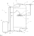
- the invention relates to a vastly improved system (1) suitable for receiving, storing and supplying water as illustrated in Fig. 1 to Fig. 4 , said system (1) comprising: a tank (2) having a first and a second outlets (10, 7) to supply water in the tank (2) to a heat exchanger (12), and a first and a second inlets (7, 5) to return water heated by the heat exchanger (12) to the tank (2), and a third inlet (3) to introduce tap water to the tank (2), and a third outlet and fourth outlet (9, 11) to supply domestic hot water, and configured to hold water for domestic use, said tank (2) comprising a bottom section, a top section and a middle section, and configured to the first outlet (10) and third inlet (3) to be located in the bottom section, the first inlet (7), second outlet (7) and fourth outlet (11) to be located in the middle section, and the second inlet (5) and the third outlet (9) to be located in the top section, and a heat exchanger (12) equipped with an inlet configured to receive
- the presence of multiple inlets at different heights permits, advantageously, the injection of water having a temperature, which temperature is different than that of the water already present inside the tank (2).
- the temperature of specific volumes of water inside the tank can be modified by injecting water having a specific temperature.
- the capability of modifying the temperature of predetermined volumes of water inside the tank (2) permits, advantageously, the stratification of the water volume contained in said tank (2).
- the terms “stratification” and “stratified” define, respectively, the action and state of separation of a water column into different layers having different temperatures. Each of said layers having a substantially uniform temperature.
- turbulent is defined as a fluid motion characterized by chaotic changes in pressure and flow velocity. Vortices are a major component of a turbulent flow.
- vortex or “vortices” are defined as regions of a fluid in which the flow revolves around an axial line, which line can be either straight or curved.
- outlet is understood as any connection which permits water to be extracted from the tank.
- inlet is understood as any connection which permits water to be injected into the tank.
- the heating circuit further comprising a first 3-way valve (20), second 3-way valve (19) and a bypass pipe (22), wherein the first 3-way (20) valve is fluidly connected to the first outlet (10), the inlet of the heat exchanger (12) and one of the end of the bypass pipe (22), and, the second 3-way valve (19) is fluidly connected to the second inlet (5), the outlet of the heat exchanger (12) and the other end of the bypass pipe (22), and, the second outlet (7) and the first inlet (7) is fluidly connected to the middle of the pipe.
- the first and second 3-way valves (20, 19) permit, advantageously, the extraction of water from the second outlet (7) and first outlet (7) of the tank, which water can then be heated and reintroduced into the tank (2).
- Said 3-way valves (19, 20) permits also, advantageously, the reintroduction of said water after heating and into the tank (2) via either the first inlet (7) or the second inlet (5).
- the system (1) further includes a controller, said controller controls the first 3-way valve (20) and the second 3-way valve (19).
- Said controller permits, advantageously, the clear definition of heating cycles and their management. This permits, very advantageously, to optimize the heating cycles according to consumption patterns, state of the water inside the tank (2), and such that energy used to heat the water in the tank is more efficiently used.
- the first inlet (7) is further equipped with a diffuser.
- a diffuser is disposed in to the third inlet (3). In this way, introduction of vortices in the middle section of the tank (2) is advantageously avoided, thus preventing destruction of any existing stratification.
- a diffuser is disposed to at least the first inlet (7), the second inlet (5) and third inlet (3).
- said diffusers are disposed to each of the first inlet (7), the second inlet and third inlet (3).
- diffuser is to be understood as a device mounted and/or extending from a pipe section, and configured to reduce the speed of water admitted into said diffuser, with said water then being discharged from the said diffuser.
- a plurality of diffusers comprising a first bowl shape diffuser (4) and a second bowl shape diffuser (6)
- the first bowl shape diffuser (4) is located close to the bottom of the tank (2) and so that an open side of the bowl shape is downwards and the axial direction of the first bowl shape diffuser (4) is vertical
- the second bowl shape diffuser (6) is located close to an upper wall of the tank (2) and so that an open side of the bowl shape is upwards and the axial direction of the second bowl shape diffuser (6) is vertical.
- the first bowl shape diffuser (4) is disposed to the third inlet (3) and the second bowl shape diffuser (6) is disposed in the second inlet (5).
- the water injected into the tank (2) through any of the bowl shaped diffusers (5, 6) has a lower velocity and which water is uniformly distributed around said diffusers and along the inner surface of the tank (2).
- the water injected into the tank (2) flows in a substantially horizontal direction, thereby avoiding disturbing the limits of the water layers where it is injected.
- the first bowl shape diffuser (4) and the second bowl shape diffuser (6) are disposed to both the third inlet (3) and the second inlet (5), respectively, is described.
- the first bowl shape diffuser (4) or the second bowl shape diffuser (6) may be disposed to either the third inlet (3) or the second inlet (5).
- the present embodiment makes available a system which permits, compared to similar devices in prior art, a much improved stratification of water contained in the water tank.
- the diffusers further comprising a third diffuser (8), and the third diffuser (8) is located in the middle section of the tank, said third diffuser (8) being preferably disposed to the first inlet.
- Said third diffuser (8) comprises a first disk equipped with an center inlet and a second similar sized, preferably equal sized disk to be placed parallel to the first disk, said disks being spaced apart by a plurality of struts extending towards said disks, and a substantially cylindrical space defined by said parallel arranged disks into which water admitted through the central inlet of the first disk flows and from which said water is radially discharged through the radial outlet between the two disks; characterized in that, a plurality of parallel arranged deflection elements vertically extending from one or both disks, said deflection elements being contained within the cylindrical space between the disks.
- the water injected into the tank (2) through the third diffuser (8) has a lower velocity and which water is uniformly distributed around said diffuser in a substantially horizontal direction. This permits, advantageously, to introduce water into the tank (2) with minimal disturbance to the limits of the water layers where said water is injected.
- the second outlet (7) and the first inlet (7) are the same. In this way, assembly of the system is greatly simplified, thereby decreasing unit costs. Furthermore, by combining the second outlet (7) and the first inlet (7), fewer cuts in the insulation of the tank (2) are necessary, thereby allowing for better preservation of the energy contained within the tank (2). Also, since the second outlet (7) and the first inlet (7) are the same, to dispose the third diffuser at the first inlet means to dispose the third diffuser at the second outlet. That is, the third diffuser can be said to have both the functions of an inlet of water flowing into the tank (2) and an outlet of water flowing out of the tank (2). The third diffuser functions as a water inlet or water outlet.
- the third diffuser is a water inlet, the water flows into a substantially cylindrical space defined by said parallel arranged disks from the central inlet of the first disc, and the water is discharged through the radial outlet between the two discs. If the third diffuser is a water outlet, the water flows into a substantially cylindrical space defined by said parallel arranged disks from the radial inlet between the two discs, and the water is discharged from the central outlet of the first disc.
- the first bowl shape diffuser (4) and the second bowl shape diffuser (6) are respectively disposed to both the third inlet (3) and the second inlet (5) is described.
- the third diffuser may be configured to be disposed at the first inlet/second outlet.
- a system makes available a system which permits, compared to similar devices in prior art, a much improved stratification of water contained in the water tank.
- the third diffuser may be disposed to the first inlet/second outlet.
- a system makes available a system which permits, compared to similar devices in prior art, an improved stratification of water contained in the water tank.
- the system is provided with a third 3-way valve (21), wherein the third 3-way valve is fluidly connected to the third outlet (9), the fourth outlet (11) and the end of a supply pipe for DHW, and is configured to mix the water from the third outlet (9) with the water from the fourth outlet (11) if needed.
- DHW Domestic Hot Water
- the third 3-way valve permits, advantageously, modulation of the flow of the water extracted from the third outlet (9) and the water from the fourth outlet (11). In this way, a broad range of temperatures is made available for consumption. Furthermore, by providing access to water coming from the fourth outlet (11), water having a medium temperature is made available without depleting the hot water layer (15). In this way, the energy contained in the system is, advantageously, better preserved.
- each inlet and outlet located in each section are located at the same height. In this way, it is possible to access water at substantially the same temperature at which said water is injected into the tank.
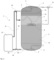
- the present invention is also reached by method for achieving stratification inside a water tank (2), said method comprising a first heating cycle as illustrated in Fig. 2 .
- a heating cycle cold water is extracted from a cold water layer (13), through the first outlet (10).
- Said cold water flow (16) is further directed by means of the first 3-way valve (20) towards the inlet of the heat exchanger (12).
- Said cold water flow (16) is heated inside the heat exchanger (12), from which said water is dispensed as a hot water flow (17).
- Said water flow is further directed by means of the second 3-way valve (19) towards the second outlet/first inlet (7), through the third diffuser (8) and into tank (2) where it is allowed to mix with cold water at the top of cold water layer (13).
- a medium temperature water layer (14) is formed and/or augmented.
- Said methods also include two alternative second heating cycles, one illustrated in Fig. 3 and the other in Fig.4 . Either one of these second heating cycles includes the extraction of medium temperature water from the tank (2), heating said medium temperature water and introducing said heated water into the top section of the tank, thereby creating a layer of hot water (15).
- the medium temperature layer created by using the aforementioned method advantageously provides a buffer between any bottom cold water layer (13) and any top hot water layer. Furthermore, the introduction of hot water near the top of the tank (2) during the second heating cycle advantageously permits the immediate creation and/or increase of a top hot water layer (15). The introduction of hot water always on top of colder layers advantageously avoids the creation buoyancy forces resulting from injecting a lower density fluid into or below a higher density fluid. This advantageously permits a faster stratification of the water inside the tank (2).
- the first heating cycle is maintained until no more cold water remains at the bottom of the tank (2), resulting in the situation illustrated in Fig. 3 .
- This permits the extraction of medium temperature water (18) through either the first outlet (10) or second outlet (7) during the second heating cycle.
- a cold water layer (13) may still be preserved at the bottom of the tank (2).
- Water having a medium temperature is extracted from the medium temperature water layer (14) through the third diffuser (8) and subsequently through second outlet/first inlet (7).
- the medium temperature water flow (18) leaving the tank (2) through the second outlet/first inlet (7) is then blocked by the second 3-way valve (19) and directed by the first 3-way valve (20) towards and into the inlet of the heat exchanger (12).
- medium temperature water flow (18) is heated and dispensed through the outlet of heat exchanger (12) as a hot water flow (17). Said hot water flow is subsequently directed by the second 3-way valve (19) towards the second inlet (5).
- Said hot water flow (17) then enters the tank (2), where it creates and/or enlarges a hot water layer (15). In this way, at least three layers of water (13, 14, 15) are preserved in the tank (2), which permit, advantageously, immediate access to cold, hot and medium temperature water.
Landscapes
- Engineering & Computer Science (AREA)
- Physics & Mathematics (AREA)
- Thermal Sciences (AREA)
- Mechanical Engineering (AREA)
- General Engineering & Computer Science (AREA)
- Water Supply & Treatment (AREA)
- Chemical & Material Sciences (AREA)
- Combustion & Propulsion (AREA)
- Heat-Pump Type And Storage Water Heaters (AREA)
Abstract
Description
- The present invention relates to systems and methods of filling hot water tanks. In particular, the present invention relates to a system and method of filling a hot water tank having multiple water strata with different temperatures.
- Hot water tanks are broadly used in domestic applications as thermal and energy storage systems. To achieve high performance during the use of domestic hot water, and better energy and thermal storage capacity, it is necessary to have a highly stratified tank. Hot-water stratified storage tanks are widely known. They serve as far as possible to prevent mixing of hotter and colder water components when loading the storage tank. In this way, heat energy is maintained at the highest possible temperature and thus can be used efficiently.
- In this context, stratification is understood as the occurrence and maintenance of adjacent, vertically distributed masses of water of different temperature and density. In a stratified tank, a cold layer of water is present at the bottom of the tank by virtue of its higher density. In the same stratified tank, a hot water layer is present at the top of the water column due to its lower density. These two water layers are separated by a medium temperature middle layer commonly referred to as thermocline.
- As is typical of its function, a domestic water tank is subject to introduction and extraction of water. This water, either supplied or extracted, can range from cold to hot. It is particularly advantageous if warm water can be directly introduced within the warm water layer already present within the water tank. This permits, though not limited to, a faster availability of hot water. In a similar way, it is advantageous to introduce cold water within the cold water layer inside the water tank.
- Japanese patent application JPS5986847A discloses a conventional hot water storage tank with a means for storing hot water with little turbulence, which comprises two bowl-shaped means arranged in opposite directions and one inside the other. This will expand the hot water flow.
- Since in a stratified storage tank the water introduced in the vicinity of the layer corresponding to the inlet temperature rises or descends due to temperature-dependent density differences and thus reaches the layer at the same temperature, particularly high requirements are placed on storage free of turbulence in stratified storage tanks.
- Known stratified charge storage tanks or stratified storage tanks, which are known for example from
DE8310135U1 , have a storage tank filled with water, in which, due to the different density, a stratification is created between the warm water located in the upper area of the storage tank and the cold water located in the lower area. To charge the stratified storage tank, a charging circuit with a circulation pump is provided, the cooler water being conveyed from the lower area of the stratified storage tank to a heat exchanger, where it is heated and the heated water is fed back into the upper area of the storage tank. For consumption, the warm water is taken from the storage tank in the upper area as process water and replaced by cold water supplied below. Other examples can be found inUS2017023263 ,WO2020196654 . US '263 discloses a hot water supply system including a liquid heater for heating a liquid, a liquid-water heat exchanger, a water-heating circuit in which the liquid is circulated between the liquid heater and the liquid-water heat exchanger. A lower outward path for leads water from a lower part of a hot water storage tank to the liquid-water heat exchanger, the upper return path for leading the water from the liquid-water heat exchanger to an upper part of the hot water storage tank, a middle outward path for leading the water from a middle part of the hot water storage tank to the liquid-water heat exchanger, a middle return path for leading the water from the liquid-water heat exchanger to a middle part of the hot water storage tank. WO '654 discloses a hot water storage state in which a low-temperature layer, a medium-temperature layer, and a high-temperature layer are formed in a tank, a first hot water supply operation is executed in which water in the medium-temperature layer is heated to a first temperature by a heating unit and supplied to a hot water destination through a hot water supply flow path. - From
DE 3835096C1 a stratified storage tank with a storage tank with a hot water supply in the upper section and a cold water supply and cold water extraction point in the bottom area is already known. The hot water supply has a flow guide device in the form of a guide tube, which brings the supplied hot water of the loading circuit into the depth of the storage tank by means of an elongated entry zone. At the cold water tap or cold water supply line In the bottom area of the storage tank, a water connection piece is provided with a cup-shaped flow braking device. The aim of these measures is to ensure that there are largely only laminar and turbulence-free flows within the storage tank and that the flow speeds remain limited so that the flow does not develop an injector effect through which colder water can be carried away into the upper storage volume area or, conversely, hot water in the lower storage volume area could be promoted. - Neither the guide device at the hot water inlet by means of the guide pipe nor the flow brake at the cold water inlet or at the cold water extraction point ensure that a radial component of the flow distributes the water supplied evenly over the entire circumference.
-
JP2011127856 -
EP2698584 discloses a pressure less accumulator for district heating systems, comprising a tank connected to at least one heat emitting system and at least one heat absorbing system. The tank comprises a lid, a bottom section and a top section. The bottom section comprises at least one first bottom inlet/outlet. The tank further comprises a partition wall arranged between the bottom section and the top section for the purpose of dividing the tank in a first compartment arranged above the partition wall and a second compartment arranged beneath the partition wall. The first compartment and the second compartment are in fluid communication with each other by at least one conduit. The first compartment comprises a first heat transfer medium and the second compartment comprises a second heat transfer medium. The second compartment further comprises a first top inlet/outlet arranged in the top of the second compartment. -
EP0928940A2 discloses a water heater baffle comprising an inlet and an outlet for the passage of water there through, wherein that the baffle arrangement forces the water entering the baffle through a labyrinth before exiting the baffle in a direction substantially 90° to its general flow of entry into the baffle. - The aforementioned concepts and embodiments present a number of approaches to achieve stratification inside a water tank. However, the devices and methods of achieving stratification disclosed in these documents are directed at dispensing only hot water. Furthermore, the abovementioned devices and methods do not consider if the temperature of the water introduced into the tank is sufficiently high such that effective stratification can be attained/preserved. This aspect greatly limits the scope of use of the concerned devices.
- The way in which hot water is produced to load the tank and differences in domestic water consumption between households make it particularly necessary to be able to control the volume of each water layer included in the stratified water column within a water tank. It is therefore an important aspect of the performance of a water storage tank to be able to create, store and provide adequate volumes of water at different temperatures, and to do so in an energetically efficient way.
- The present invention aims to resolve at least some of the problems and disadvantages mentioned above.
- The present invention and embodiments thereof serve to provide a solution to one or more of the above-mentioned disadvantages. To this end, the present invention relates to a system, which comprises a tank having multiple water strata with different temperatures according to
claim 1. - It is an object of the present invention to make available a system which permits, compared to similar devices in prior art, a much improved stratification of water contained in a water tank. Said tank being further configured to be connected to a domestic water network.
- It is a particular object of the invention to make available a system which more than superior stratification, permits a much advantageous and superior control over the stratification process. In particular, it is possible to adjust the volume of the water layers included in the stratified water column contained in the water tank.
- It is a further object of the invention to make available a method of achieving a much superior stratification, which method makes use of the superior stratification capabilities and enhanced control enabled by the aforementioned system. In particular, said method permits a plurality of approaches to achieving improved stratification. in a far more efficient use of energy in order to attain said stratification.
- According to an aspect of the invention, a system is made available, which system comprises a tank, a heat exchanger and a heating circuit encompassing said first two elements. Also, the tank has a plurality of inlets and outlets. In particular, the system is connected to the heating circuit configured to provide a fluid connection between an outlet of the heat exchanger and any one of the inlets and configured to provide a fluid connection between an inlet of the heat exchanger and any one of the outlets. Furthermore, the system is configured to be connected to a domestic water network via a plurality of outlets positioned along the height of the water tank. This permits, advantageously, direct access to different water layers within the tank, each of said water layers having a different temperature.
- According to a second aspect of the invention, a method of achieving stratification is made available. Said method permitting multiple approaches to yielding superior stratification results and much enhanced efficiency.
-
-
Figure 1 illustrates an embodiment of the tank-type system and all the elements of said system. -
Figure 2 illustrates an embodiment the first heating cycle. -
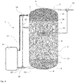
Figure 3 illustrates an embodiment of a second heating cycle. -
Figure 4 illustrates an embodiment of an alternative second heating cycle. - The present invention concerns a method of filling a hot water tank having multiple water strata with different temperatures.
- Unless otherwise defined, all terms used in disclosing the invention, including technical and scientific terms, have the meaning as commonly understood by one of ordinary skill in the art to which this invention belongs. By means of further guidance, term definitions are included to better appreciate the teaching of the present invention.
- As used herein, the following terms have the following meanings:
"A", "an", and "the" as used herein refers to both singular and plural referents unless the context clearly dictates otherwise. By way of example, "a compartment" refers to one or more than one compartment. - "Comprise", "comprising", and "comprises" and "comprised of" as used herein are synonymous with "include", "including", "includes" or "contain", "containing", "contains" and are inclusive or open-ended terms that specifies the presence of what follows e.g. component and do not exclude or preclude the presence of additional, non-recited components, features, element, members, steps, known in the art or disclosed therein.
- Furthermore, the terms first, second, third and the like in the description and in the claims, are used for distinguishing between similar elements and not necessarily for describing a sequential or chronological order, unless specified. It is to be understood that the terms so used are interchangeable under appropriate circumstances and that the embodiments of the invention described herein are capable of operation in other sequences than described or illustrated herein.
- The recitation of numerical ranges by endpoints includes all numbers and fractions subsumed within that range, as well as the recited endpoints.
- Whereas the terms "one or more" or "at least one", such as one or more or at least one member(s) of a group of members, is clear per se, by means of further exemplification, the term encompasses inter alia a reference to any one of said members, or to any two or more of said members, such as, e.g., any ≥3, ≥4, ≥5, ≥6 or ≥7 etc. of said members, and up to all said members.
- In a first aspect, the invention relates to a vastly improved system (1) suitable for receiving, storing and supplying water as illustrated in
Fig. 1 to Fig. 4 , said system (1) comprising:
a tank (2) having a first and a second outlets (10, 7) to supply water in the tank (2) to a heat exchanger (12), and a first and a second inlets (7, 5) to return water heated by the heat exchanger (12) to the tank (2), and a third inlet (3) to introduce tap water to the tank (2), and a third outlet and fourth outlet (9, 11) to supply domestic hot water, and configured to hold water for domestic use, said tank (2) comprising a bottom section, a top section and a middle section, and configured to the first outlet (10) and third inlet (3) to be located in the bottom section, the first inlet (7), second outlet (7) and fourth outlet (11) to be located in the middle section, and the second inlet (5) and the third outlet (9) to be located in the top section, and a heat exchanger (12) equipped with an inlet configured to receive water in the tank (2) and an outlet configured to supply said water to the tank, and a heating circuit configured to provide a fluid connection between the outlet of the heat exchanger (12) and either the first inlet (7) or the second inlet (5), and configured to provide a fluid connection between the inlet of the heat exchanger and either the first outlet (10) or the second outlet (7). - The presence of multiple inlets at different heights permits, advantageously, the injection of water having a temperature, which temperature is different than that of the water already present inside the tank (2). In this way, the temperature of specific volumes of water inside the tank can be modified by injecting water having a specific temperature. The capability of modifying the temperature of predetermined volumes of water inside the tank (2) permits, advantageously, the stratification of the water volume contained in said tank (2).
- In this context, the terms "stratification" and "stratified" define, respectively, the action and state of separation of a water column into different layers having different temperatures. Each of said layers having a substantially uniform temperature. In this context, "turbulence" is defined as a fluid motion characterized by chaotic changes in pressure and flow velocity. Vortices are a major component of a turbulent flow. The terms "vortex" or "vortices" are defined as regions of a fluid in which the flow revolves around an axial line, which line can be either straight or curved.
- In this context "outlet" is understood as any connection which permits water to be extracted from the tank. In this context "inlet" is understood as any connection which permits water to be injected into the tank.
- According to a further or another embodiment, the heating circuit further comprising a first 3-way valve (20), second 3-way valve (19) and a bypass pipe (22), wherein the first 3-way (20) valve is fluidly connected to the first outlet (10), the inlet of the heat exchanger (12) and one of the end of the bypass pipe (22), and, the second 3-way valve (19) is fluidly connected to the second inlet (5), the outlet of the heat exchanger (12) and the other end of the bypass pipe (22), and, the second outlet (7) and the first inlet (7) is fluidly connected to the middle of the pipe.
- The first and second 3-way valves (20, 19) permit, advantageously, the extraction of water from the second outlet (7) and first outlet (7) of the tank, which water can then be heated and reintroduced into the tank (2). Said 3-way valves (19, 20) permits also, advantageously, the reintroduction of said water after heating and into the tank (2) via either the first inlet (7) or the second inlet (5).
- According to a further or another embodiment, the system (1) further includes a controller, said controller controls the first 3-way valve (20) and the second 3-way valve (19). Said controller permits, advantageously, the clear definition of heating cycles and their management. This permits, very advantageously, to optimize the heating cycles according to consumption patterns, state of the water inside the tank (2), and such that energy used to heat the water in the tank is more efficiently used.
- Any vortices occurring at or near the middle section of the water tank (2) are particularly harmful to the formation and maintenance of stratification since separation between layers of water having different temperature often occurs in this middle section. It is therefore considerably advantageous to avoid the formation of vortices in the middle section of the tank (2). To this end and according to a further embodiment, the first inlet (7) is further equipped with a diffuser. In a further embodiment, a diffuser is disposed in to the third inlet (3). In this way, introduction of vortices in the middle section of the tank (2) is advantageously avoided, thus preventing destruction of any existing stratification.
- According to a further or another embodiment, a diffuser is disposed to at least the first inlet (7), the second inlet (5) and third inlet (3). Preferably, said diffusers are disposed to each of the first inlet (7), the second inlet and third inlet (3). This permits an advantageous mitigation of turbulence and velocity of the water being injected into the tank (2). In this way, disturbance of the limits between water layers is advantageously minimized.
- In the present context, "diffuser" is to be understood as a device mounted and/or extending from a pipe section, and configured to reduce the speed of water admitted into said diffuser, with said water then being discharged from the said diffuser.
- According to a further or another embodiment, a plurality of diffusers comprising a first bowl shape diffuser (4) and a second bowl shape diffuser (6), and the first bowl shape diffuser (4) is located close to the bottom of the tank (2) and so that an open side of the bowl shape is downwards and the axial direction of the first bowl shape diffuser (4) is vertical, and the second bowl shape diffuser (6) is located close to an upper wall of the tank (2) and so that an open side of the bowl shape is upwards and the axial direction of the second bowl shape diffuser (6) is vertical. By preference the first bowl shape diffuser (4) is disposed to the third inlet (3) and the second bowl shape diffuser (6) is disposed in the second inlet (5). In this way, the water injected into the tank (2) through any of the bowl shaped diffusers (5, 6) has a lower velocity and which water is uniformly distributed around said diffusers and along the inner surface of the tank (2). In this way, the water injected into the tank (2) flows in a substantially horizontal direction, thereby avoiding disturbing the limits of the water layers where it is injected. In the present embodiment, an example in which the first bowl shape diffuser (4) and the second bowl shape diffuser (6) are disposed to both the third inlet (3) and the second inlet (5), respectively, is described. But the first bowl shape diffuser (4) or the second bowl shape diffuser (6) may be disposed to either the third inlet (3) or the second inlet (5). Furthermore, even when neither the first bowl shape diffuser (4) or the second bowl shape diffuser (6) are disposed to both the third inlet (3) and the second inlet (5), the present embodiment makes available a system which permits, compared to similar devices in prior art, a much improved stratification of water contained in the water tank.
- According to a further or another embodiment, the diffusers further comprising a third diffuser (8), and the third diffuser (8) is located in the middle section of the tank, said third diffuser (8) being preferably disposed to the first inlet. Said third diffuser (8)comprises a first disk equipped with an center inlet and a second similar sized, preferably equal sized disk to be placed parallel to the first disk, said disks being spaced apart by a plurality of struts extending towards said disks, and a substantially cylindrical space defined by said parallel arranged disks into which water admitted through the central inlet of the first disk flows and from which said water is radially discharged through the radial outlet between the two disks; characterized in that, a plurality of parallel arranged deflection elements vertically extending from one or both disks, said deflection elements being contained within the cylindrical space between the disks.
- In this way, the water injected into the tank (2) through the third diffuser (8) has a lower velocity and which water is uniformly distributed around said diffuser in a substantially horizontal direction. This permits, advantageously, to introduce water into the tank (2) with minimal disturbance to the limits of the water layers where said water is injected.
- According to a further or another embodiment, the second outlet (7) and the first inlet (7) are the same. In this way, assembly of the system is greatly simplified, thereby decreasing unit costs. Furthermore, by combining the second outlet (7) and the first inlet (7), fewer cuts in the insulation of the tank (2) are necessary, thereby allowing for better preservation of the energy contained within the tank (2). Also, since the second outlet (7) and the first inlet (7) are the same, to dispose the third diffuser at the first inlet means to dispose the third diffuser at the second outlet. That is, the third diffuser can be said to have both the functions of an inlet of water flowing into the tank (2) and an outlet of water flowing out of the tank (2). The third diffuser functions as a water inlet or water outlet. If the third diffuser is a water inlet, the water flows into a substantially cylindrical space defined by said parallel arranged disks from the central inlet of the first disc, and the water is discharged through the radial outlet between the two discs. If the third diffuser is a water outlet, the water flows into a substantially cylindrical space defined by said parallel arranged disks from the radial inlet between the two discs, and the water is discharged from the central outlet of the first disc. In the embodiment described above, an example in which the first bowl shape diffuser (4) and the second bowl shape diffuser (6) are respectively disposed to both the third inlet (3) and the second inlet (5) is described. Furthermore, the third diffuser may be configured to be disposed at the first inlet/second outlet. In this embodiment, a system makes available a system which permits, compared to similar devices in prior art, a much improved stratification of water contained in the water tank. However, only the third diffuser may be disposed to the first inlet/second outlet. In this case also, a system makes available a system which permits, compared to similar devices in prior art, an improved stratification of water contained in the water tank.
- According to a further or another embodiment, the system is provided with a third 3-way valve (21), wherein the third 3-way valve is fluidly connected to the third outlet (9), the fourth outlet (11) and the end of a supply pipe for DHW, and is configured to mix the water from the third outlet (9) with the water from the fourth outlet (11) if needed.
- In this context, "DHW" is an abbreviation for "Domestic Hot Water". The third 3-way valve permits, advantageously, modulation of the flow of the water extracted from the third outlet (9) and the water from the fourth outlet (11). In this way, a broad range of temperatures is made available for consumption. Furthermore, by providing access to water coming from the fourth outlet (11), water having a medium temperature is made available without depleting the hot water layer (15). In this way, the energy contained in the system is, advantageously, better preserved.
- By preference, each inlet and outlet located in each section are located at the same height. In this way, it is possible to access water at substantially the same temperature at which said water is injected into the tank.
- The present invention is also reached by method for achieving stratification inside a water tank (2), said method comprising a first heating cycle as illustrated in
Fig. 2 . In said heating cycle cold water is extracted from a cold water layer (13), through the first outlet (10). Said cold water flow (16) is further directed by means of the first 3-way valve (20) towards the inlet of the heat exchanger (12). Said cold water flow (16) is heated inside the heat exchanger (12), from which said water is dispensed as a hot water flow (17). Said water flow is further directed by means of the second 3-way valve (19) towards the second outlet/first inlet (7), through the third diffuser (8) and into tank (2) where it is allowed to mix with cold water at the top of cold water layer (13). By virtue of this hot water flow (19) into the middle section of tank (2), a medium temperature water layer (14) is formed and/or augmented. Said methods also include two alternative second heating cycles, one illustrated inFig. 3 and the other inFig.4 . Either one of these second heating cycles includes the extraction of medium temperature water from the tank (2), heating said medium temperature water and introducing said heated water into the top section of the tank, thereby creating a layer of hot water (15). - The medium temperature layer created by using the aforementioned method advantageously provides a buffer between any bottom cold water layer (13) and any top hot water layer. Furthermore, the introduction of hot water near the top of the tank (2) during the second heating cycle advantageously permits the immediate creation and/or increase of a top hot water layer (15). The introduction of hot water always on top of colder layers advantageously avoids the creation buoyancy forces resulting from injecting a lower density fluid into or below a higher density fluid. This advantageously permits a faster stratification of the water inside the tank (2).
- In a further or another embodiment of the invention, the first heating cycle is maintained until no more cold water remains at the bottom of the tank (2), resulting in the situation illustrated in
Fig. 3 . This permits the extraction of medium temperature water (18) through either the first outlet (10) or second outlet (7) during the second heating cycle. - In the embodiment illustrated in
Fig.3 , during the second heating cycle, water having a medium temperature is then extracted from the medium temperature water layer (14) through the first outlet (10). The mediumtemperature water flow 18 leaving the tank (2) through the first outlet (10) is then directed by the first 3-way valve (20) towards and into the inlet of the heat exchanger (12). Inside said heat exchanger (12), medium temperature water flow (18) is heated and dispensed through the hot water outlet of heat exchanger (12) as a hot water flow (17). Said hot water flow is subsequently directed by the second 3-way valve (19) towards second inlet (5). Said hot water flow (17) then enters the tank (2), where it creates and/or enlarges a hot water layer (15). In this way, a higher volume of hot water can be made available as the cold water layer (13) at the bottom of the tank has been depleted and turned into warm water. - In an alternative embodiment of the second heating cycle as illustrated in
Fig.4 , a cold water layer (13) may still be preserved at the bottom of the tank (2). Water having a medium temperature is extracted from the medium temperature water layer (14) through the third diffuser (8) and subsequently through second outlet/first inlet (7). The medium temperature water flow (18) leaving the tank (2) through the second outlet/first inlet (7) is then blocked by the second 3-way valve (19) and directed by the first 3-way valve (20) towards and into the inlet of the heat exchanger (12). Inside said heat exchanger (12), medium temperature water flow (18) is heated and dispensed through the outlet of heat exchanger (12) as a hot water flow (17). Said hot water flow is subsequently directed by the second 3-way valve (19) towards the second inlet (5). Said hot water flow (17) then enters the tank (2), where it creates and/or enlarges a hot water layer (15). In this way, at least three layers of water (13, 14, 15) are preserved in the tank (2), which permit, advantageously, immediate access to cold, hot and medium temperature water. -
- 1
- system
- 2
- tank
- 3
- third inlet for tap water
- 4
- first bowl shape diffuser
- 5
- second inlet
- 6
- second bowl shape diffuser
- 7
- second outlet/first inlet
- 8
- third diffuser
- 9
- third outlet
- 10
- first outlet
- 11
- fourth outlet
- 12
- heat exchanger
- 13
- cold water layer
- 14
- medium temperature water layer
- 15
- hot water layer
- 16
- cold water flow
- 17
- hot water flow
- 18
- medium temperature water flow
- 19
- second 3-way valve
- 20
- first 3-way valve
- 21
- third 3-way valve
- 22
- bypass pipe
Claims (12)
- A system suitable for receiving, storing and supplying water, said system comprising:a tank having a first and a second outlets to supply water in the tank to a heat exchanger, and a first and a second inlets to return water heated by the heat exchanger to the tank, and a third inlet to introduce tap water to the tank, and a third outlet and fourth outlet to supply domestic hot water, and configured to hold water for domestic use, said tank comprising a bottom section, a top section and a middle section and configured to the first outlet and third inlet to be located in the bottom section, the first inlet, second outlet and fourth outlet to be located in the middle section, and the second inlet and the third outlet to be located in the top section, anda heat exchanger equipped with an inlet configured to receive water in the tank and an outlet configured to supply said water to the tank,a heating circuit configured to provide a fluid connection between the outlet of the heat exchanger and either the first inlet or the second inlet, and configured to provide a fluid connection between the inlet of the heat exchanger and either the first outlet or the second outlet.
- A system according to claim 1, said heating circuit further comprising a first 3-way valve (20), second 3-way valve (19) and a bypass pipe, wherein the first 3-way valve (20) is fluidly connected to the first outlet, the inlet of the heat exchanger and one of the end of the bypass pipe, and,
the second 3-way valve (19) is fluidly connected to the second inlet, the outlet of the heat exchanger and the other end of the bypass pipe, and, the second outlet and the first inlet is fluidly connected to the middle of the bypass pipe. - A system according to claim 2, further comprising a controller, said controller controls the first 3-way valve and the second 3-way valve.
- A system according to any one of claims 1 to 3, further comprising a diffuser, said diffuser is disposed to at least the first inlet, the second inlet and third inlet.
- A system according to claim 4, said diffusers are disposed to each of the first inlet, the second inlet and third inlet.
- A system according to claim 4, further comprising a plurality of diffusers comprising a first bowl shape diffuser and a second bowl shape diffuser, and the first bowl shape diffuser is located close to the bottom of the tank and so that an open side of the bowl is downwards and the axial direction of the first bowl shape diffuser is vertical, and the second bowl shape diffuser is located close to an upper wall of the tank and so that an open side of the bowl is upwards and the axial direction of the second bowl shape diffuser is vertical, and the first bowl shape diffuser is disposed to the third inlet and the second bowl shape diffuser is disposed in the second inlet.
- A system according to claim 4 or 6, further comprising a third diffuser, and the third diffuser is located in the middle section of the tank and is disposed to the first inlet and comprises:a first disk equipped with a center inlet anda second similar sized, preferably equal sized disk to be placed parallel to the first disk, said disks being spaced apart by a plurality of struts extending towards said disks, and;a substantially cylindrical space defined by said parallel arranged disks into which water admitted through the central inlet of the first disk flows and from which said water is radially discharged through the radial outlet between the two disks;characterized in that, a plurality of parallel arranged deflection elements vertically extending from one or both disks, said deflection elements being contained within the cylindrical space between the disks.
- A system according to any one of claims 1 to 7, the second outlet and the first inlet are the same.
- A system according to claim 8, the third diffuser functions as a water inlet or water outlet.
- A system according to any one of claims 1 to 9, further comprising
a third 3-way valve, wherein the third 3-way valve is fluidly connected to the third outlet, the fourth outlet and the end of a supply pipe for DHW, and is configured to mix the water from the third outlet with the water from the fourth outlet. - A system according to claim 10, wherein each inlet and outlet located in each section are located at the same height.
- A method for achieving stratification inside a water tank according to any of claims 1 to 11, said method comprising:a first heating cycle, said heating cycle including the extraction of cold water from the bottom of the tank, heating of said water and introducing said heated water into the middle section of the tank, thereby creating a layer of medium temperature water, the first heating cycle is maintained until no more cold water remains at the bottom of the tank;a second heating cycle, said heating cycle including the extraction of medium temperature water from the tank, heating said medium temperature water and introducing said heated water into the top section of the tank, thereby creating a layer of hot water, the medium temperature water is extracted from the tank through an outlet next to the bottom of the tank or the middle section of the tank.
Applications Claiming Priority (1)
| Application Number | Priority Date | Filing Date | Title |
|---|---|---|---|
| BE20215613A BE1029647B1 (en) | 2021-08-02 | 2021-08-02 | A SYSTEM AND METHOD FOR ACHIEVING LAYERING IN A HOT WATER TANK |
Publications (2)
| Publication Number | Publication Date |
|---|---|
| EP4130582A1 true EP4130582A1 (en) | 2023-02-08 |
| EP4130582B1 EP4130582B1 (en) | 2025-04-30 |
Family
ID=77914200
Family Applications (1)
| Application Number | Title | Priority Date | Filing Date |
|---|---|---|---|
| EP22187941.4A Active EP4130582B1 (en) | 2021-08-02 | 2022-07-29 | A system and method for achieving stratification in a hot water tank |
Country Status (2)
| Country | Link |
|---|---|
| EP (1) | EP4130582B1 (en) |
| BE (1) | BE1029647B1 (en) |
Cited By (1)
| Publication number | Priority date | Publication date | Assignee | Title |
|---|---|---|---|---|
| WO2026075567A1 (en) * | 2024-10-03 | 2026-04-09 | De Jong Gorredijk B.V. | Stratification tank, water system comprising such a stratification tank, and method of operating such a water system |
Citations (8)
| Publication number | Priority date | Publication date | Assignee | Title |
|---|---|---|---|---|
| DE8310135U1 (en) | 1983-04-07 | 1983-08-11 | Nova-Apparatebau GmbH + Co, 7710 Donaueschingen | HOT WATER LAYER STORAGE |
| JPS5986847A (en) | 1982-11-10 | 1984-05-19 | Matsushita Electric Ind Co Ltd | hot water boiler |
| DE3835096C2 (en) | 1988-10-14 | 1991-08-29 | Martin Dipl.-Ing. Sandler (Fh), 8950 Kaufbeuren, De | |
| EP0928940A2 (en) | 1998-01-12 | 1999-07-14 | Heatrae-Sadia Heating Limited | Improvements to baffles for water heaters |
| JP2011127856A (en) | 2009-12-21 | 2011-06-30 | Corona Corp | Storage type hot water supply device |
| EP2698584A1 (en) | 2013-03-26 | 2014-02-19 | Aktiebolaget Tore J. Hedbäck | Pressureless accumulator for district heating systems |
| US20170023263A1 (en) | 2014-06-30 | 2017-01-26 | Mitsubishi Electric Corporation | Heating and hot water supply system |
| WO2020196654A1 (en) | 2019-03-27 | 2020-10-01 | ダイキン工業株式会社 | Hot water supply device |
-
2021
- 2021-08-02 BE BE20215613A patent/BE1029647B1/en not_active IP Right Cessation
-
2022
- 2022-07-29 EP EP22187941.4A patent/EP4130582B1/en active Active
Patent Citations (8)
| Publication number | Priority date | Publication date | Assignee | Title |
|---|---|---|---|---|
| JPS5986847A (en) | 1982-11-10 | 1984-05-19 | Matsushita Electric Ind Co Ltd | hot water boiler |
| DE8310135U1 (en) | 1983-04-07 | 1983-08-11 | Nova-Apparatebau GmbH + Co, 7710 Donaueschingen | HOT WATER LAYER STORAGE |
| DE3835096C2 (en) | 1988-10-14 | 1991-08-29 | Martin Dipl.-Ing. Sandler (Fh), 8950 Kaufbeuren, De | |
| EP0928940A2 (en) | 1998-01-12 | 1999-07-14 | Heatrae-Sadia Heating Limited | Improvements to baffles for water heaters |
| JP2011127856A (en) | 2009-12-21 | 2011-06-30 | Corona Corp | Storage type hot water supply device |
| EP2698584A1 (en) | 2013-03-26 | 2014-02-19 | Aktiebolaget Tore J. Hedbäck | Pressureless accumulator for district heating systems |
| US20170023263A1 (en) | 2014-06-30 | 2017-01-26 | Mitsubishi Electric Corporation | Heating and hot water supply system |
| WO2020196654A1 (en) | 2019-03-27 | 2020-10-01 | ダイキン工業株式会社 | Hot water supply device |
Cited By (1)
| Publication number | Priority date | Publication date | Assignee | Title |
|---|---|---|---|---|
| WO2026075567A1 (en) * | 2024-10-03 | 2026-04-09 | De Jong Gorredijk B.V. | Stratification tank, water system comprising such a stratification tank, and method of operating such a water system |
Also Published As
| Publication number | Publication date |
|---|---|
| BE1029647A1 (en) | 2023-02-24 |
| EP4130582B1 (en) | 2025-04-30 |
| BE1029647B1 (en) | 2023-02-27 |
Similar Documents
| Publication | Publication Date | Title |
|---|---|---|
| US8327920B2 (en) | Heat accumulator with insulated double tube structure | |
| KR20120129890A (en) | Accumulator tank with partition walls | |
| JP2011220573A (en) | Vertical electric water heater including movable separator and boiling method for the same | |
| EP4130582B1 (en) | A system and method for achieving stratification in a hot water tank | |
| AU2010249928A1 (en) | Thermal energy storage apparatus | |
| CN109140575B (en) | Thermal stratification enhanced thermal storage device | |
| CN104567479A (en) | Gas cooling device | |
| KR100943443B1 (en) | Boiler with inner tank | |
| JP2012026601A (en) | Hot water storage tank and storage type water heater | |
| WO2008027041A1 (en) | Multisection water storage tank with thermal stratification for thermal energy utilization systems | |
| US20190137189A1 (en) | Stratifier for tank-type water heater | |
| EP3312516B1 (en) | Water heater | |
| US20140003801A1 (en) | Water heating system | |
| US20050258261A1 (en) | Method for operating heating systems, heating system for carrying out the method and use thereof | |
| JP2011220574A (en) | Vertical electric water heater including circulation pipe | |
| KR20110138318A (en) | Boiler hot water tank | |
| JP2012107822A (en) | Hot water storage type water heater | |
| CN203572079U (en) | Cold and hot water layered water tank for solar water heater | |
| CN104456951A (en) | Water heating apparatus | |
| KR101767152B1 (en) | Heat storage tank | |
| CN220728520U (en) | Hot water system and water heating device | |
| JP2013213596A (en) | Heat pump water heater | |
| JP2013224823A (en) | Water heater | |
| JPH0355461A (en) | Hot water tank and hot water supply facility provided with the same | |
| CN104034012A (en) | Packing type water heater |
Legal Events
| Date | Code | Title | Description |
|---|---|---|---|
| PUAI | Public reference made under article 153(3) epc to a published international application that has entered the european phase |
Free format text: ORIGINAL CODE: 0009012 |
|
| STAA | Information on the status of an ep patent application or granted ep patent |
Free format text: STATUS: THE APPLICATION HAS BEEN PUBLISHED |
|
| AK | Designated contracting states |
Kind code of ref document: A1 Designated state(s): AL AT BE BG CH CY CZ DE DK EE ES FI FR GB GR HR HU IE IS IT LI LT LU LV MC MK MT NL NO PL PT RO RS SE SI SK SM TR |
|
| STAA | Information on the status of an ep patent application or granted ep patent |
Free format text: STATUS: REQUEST FOR EXAMINATION WAS MADE |
|
| 17P | Request for examination filed |
Effective date: 20230714 |
|
| RBV | Designated contracting states (corrected) |
Designated state(s): AL AT BE BG CH CY CZ DE DK EE ES FI FR GB GR HR HU IE IS IT LI LT LU LV MC MK MT NL NO PL PT RO RS SE SI SK SM TR |
|
| GRAP | Despatch of communication of intention to grant a patent |
Free format text: ORIGINAL CODE: EPIDOSNIGR1 |
|
| STAA | Information on the status of an ep patent application or granted ep patent |
Free format text: STATUS: GRANT OF PATENT IS INTENDED |
|
| RIC1 | Information provided on ipc code assigned before grant |
Ipc: F28D 20/00 20060101ALI20240521BHEP Ipc: F24D 3/08 20060101AFI20240521BHEP |
|
| INTG | Intention to grant announced |
Effective date: 20240625 |
|
| GRAS | Grant fee paid |
Free format text: ORIGINAL CODE: EPIDOSNIGR3 |
|
| GRAJ | Information related to disapproval of communication of intention to grant by the applicant or resumption of examination proceedings by the epo deleted |
Free format text: ORIGINAL CODE: EPIDOSDIGR1 |
|
| GRAL | Information related to payment of fee for publishing/printing deleted |
Free format text: ORIGINAL CODE: EPIDOSDIGR3 |
|
| STAA | Information on the status of an ep patent application or granted ep patent |
Free format text: STATUS: REQUEST FOR EXAMINATION WAS MADE |
|
| GRAP | Despatch of communication of intention to grant a patent |
Free format text: ORIGINAL CODE: EPIDOSNIGR1 |
|
| INTC | Intention to grant announced (deleted) | ||
| STAA | Information on the status of an ep patent application or granted ep patent |
Free format text: STATUS: GRANT OF PATENT IS INTENDED |
|
| INTG | Intention to grant announced |
Effective date: 20241121 |
|
| GRAA | (expected) grant |
Free format text: ORIGINAL CODE: 0009210 |
|
| STAA | Information on the status of an ep patent application or granted ep patent |
Free format text: STATUS: THE PATENT HAS BEEN GRANTED |
|
| AK | Designated contracting states |
Kind code of ref document: B1 Designated state(s): AL AT BE BG CH CY CZ DE DK EE ES FI FR GB GR HR HU IE IS IT LI LT LU LV MC MK MT NL NO PL PT RO RS SE SI SK SM TR |
|
| REG | Reference to a national code |
Ref country code: CH Ref legal event code: EP Ref country code: GB Ref legal event code: FG4D |
|
| REG | Reference to a national code |
Ref country code: IE Ref legal event code: FG4D |
|
| REG | Reference to a national code |
Ref country code: DE Ref legal event code: R096 Ref document number: 602022013803 Country of ref document: DE |
|
| REG | Reference to a national code |
Ref country code: NL Ref legal event code: MP Effective date: 20250430 |
|
| REG | Reference to a national code |
Ref country code: AT Ref legal event code: MK05 Ref document number: 1790323 Country of ref document: AT Kind code of ref document: T Effective date: 20250430 |
|
| P01 | Opt-out of the competence of the unified patent court (upc) registered |
Free format text: CASE NUMBER: UPC_APP_3035_4130582/2025 Effective date: 20250811 |
|
| PG25 | Lapsed in a contracting state [announced via postgrant information from national office to epo] |
Ref country code: PT Free format text: LAPSE BECAUSE OF FAILURE TO SUBMIT A TRANSLATION OF THE DESCRIPTION OR TO PAY THE FEE WITHIN THE PRESCRIBED TIME-LIMIT Effective date: 20250901 Ref country code: ES Free format text: LAPSE BECAUSE OF FAILURE TO SUBMIT A TRANSLATION OF THE DESCRIPTION OR TO PAY THE FEE WITHIN THE PRESCRIBED TIME-LIMIT Effective date: 20250430 Ref country code: FI Free format text: LAPSE BECAUSE OF FAILURE TO SUBMIT A TRANSLATION OF THE DESCRIPTION OR TO PAY THE FEE WITHIN THE PRESCRIBED TIME-LIMIT Effective date: 20250430 |
|
| PGFP | Annual fee paid to national office [announced via postgrant information from national office to epo] |
Ref country code: DE Payment date: 20250730 Year of fee payment: 4 |
|
| REG | Reference to a national code |
Ref country code: LT Ref legal event code: MG9D |
|
| PG25 | Lapsed in a contracting state [announced via postgrant information from national office to epo] |
Ref country code: GR Free format text: LAPSE BECAUSE OF FAILURE TO SUBMIT A TRANSLATION OF THE DESCRIPTION OR TO PAY THE FEE WITHIN THE PRESCRIBED TIME-LIMIT Effective date: 20250731 Ref country code: NO Free format text: LAPSE BECAUSE OF FAILURE TO SUBMIT A TRANSLATION OF THE DESCRIPTION OR TO PAY THE FEE WITHIN THE PRESCRIBED TIME-LIMIT Effective date: 20250730 |
|
| PG25 | Lapsed in a contracting state [announced via postgrant information from national office to epo] |
Ref country code: NL Free format text: LAPSE BECAUSE OF FAILURE TO SUBMIT A TRANSLATION OF THE DESCRIPTION OR TO PAY THE FEE WITHIN THE PRESCRIBED TIME-LIMIT Effective date: 20250430 Ref country code: PL Free format text: LAPSE BECAUSE OF FAILURE TO SUBMIT A TRANSLATION OF THE DESCRIPTION OR TO PAY THE FEE WITHIN THE PRESCRIBED TIME-LIMIT Effective date: 20250430 |
|
| PG25 | Lapsed in a contracting state [announced via postgrant information from national office to epo] |
Ref country code: BG Free format text: LAPSE BECAUSE OF FAILURE TO SUBMIT A TRANSLATION OF THE DESCRIPTION OR TO PAY THE FEE WITHIN THE PRESCRIBED TIME-LIMIT Effective date: 20250430 |
|
| PG25 | Lapsed in a contracting state [announced via postgrant information from national office to epo] |
Ref country code: HR Free format text: LAPSE BECAUSE OF FAILURE TO SUBMIT A TRANSLATION OF THE DESCRIPTION OR TO PAY THE FEE WITHIN THE PRESCRIBED TIME-LIMIT Effective date: 20250430 |
|
| PG25 | Lapsed in a contracting state [announced via postgrant information from national office to epo] |
Ref country code: AT Free format text: LAPSE BECAUSE OF FAILURE TO SUBMIT A TRANSLATION OF THE DESCRIPTION OR TO PAY THE FEE WITHIN THE PRESCRIBED TIME-LIMIT Effective date: 20250430 |
|
| PGFP | Annual fee paid to national office [announced via postgrant information from national office to epo] |
Ref country code: FR Payment date: 20250730 Year of fee payment: 4 |
|
| PG25 | Lapsed in a contracting state [announced via postgrant information from national office to epo] |
Ref country code: RS Free format text: LAPSE BECAUSE OF FAILURE TO SUBMIT A TRANSLATION OF THE DESCRIPTION OR TO PAY THE FEE WITHIN THE PRESCRIBED TIME-LIMIT Effective date: 20250731 |
|
| PG25 | Lapsed in a contracting state [announced via postgrant information from national office to epo] |
Ref country code: IS Free format text: LAPSE BECAUSE OF FAILURE TO SUBMIT A TRANSLATION OF THE DESCRIPTION OR TO PAY THE FEE WITHIN THE PRESCRIBED TIME-LIMIT Effective date: 20250830 |
|
| PG25 | Lapsed in a contracting state [announced via postgrant information from national office to epo] |
Ref country code: LV Free format text: LAPSE BECAUSE OF FAILURE TO SUBMIT A TRANSLATION OF THE DESCRIPTION OR TO PAY THE FEE WITHIN THE PRESCRIBED TIME-LIMIT Effective date: 20250430 |
|
| PG25 | Lapsed in a contracting state [announced via postgrant information from national office to epo] |
Ref country code: SM Free format text: LAPSE BECAUSE OF FAILURE TO SUBMIT A TRANSLATION OF THE DESCRIPTION OR TO PAY THE FEE WITHIN THE PRESCRIBED TIME-LIMIT Effective date: 20250430 Ref country code: DK Free format text: LAPSE BECAUSE OF FAILURE TO SUBMIT A TRANSLATION OF THE DESCRIPTION OR TO PAY THE FEE WITHIN THE PRESCRIBED TIME-LIMIT Effective date: 20250430 |
|
| PG25 | Lapsed in a contracting state [announced via postgrant information from national office to epo] |
Ref country code: CZ Free format text: LAPSE BECAUSE OF FAILURE TO SUBMIT A TRANSLATION OF THE DESCRIPTION OR TO PAY THE FEE WITHIN THE PRESCRIBED TIME-LIMIT Effective date: 20250430 |
|
| PG25 | Lapsed in a contracting state [announced via postgrant information from national office to epo] |
Ref country code: EE Free format text: LAPSE BECAUSE OF FAILURE TO SUBMIT A TRANSLATION OF THE DESCRIPTION OR TO PAY THE FEE WITHIN THE PRESCRIBED TIME-LIMIT Effective date: 20250430 |
|
| PG25 | Lapsed in a contracting state [announced via postgrant information from national office to epo] |
Ref country code: SK Free format text: LAPSE BECAUSE OF FAILURE TO SUBMIT A TRANSLATION OF THE DESCRIPTION OR TO PAY THE FEE WITHIN THE PRESCRIBED TIME-LIMIT Effective date: 20250430 |
|
| PG25 | Lapsed in a contracting state [announced via postgrant information from national office to epo] |
Ref country code: IT Free format text: LAPSE BECAUSE OF FAILURE TO SUBMIT A TRANSLATION OF THE DESCRIPTION OR TO PAY THE FEE WITHIN THE PRESCRIBED TIME-LIMIT Effective date: 20250430 |
|
| REG | Reference to a national code |
Ref country code: DE Ref legal event code: R097 Ref document number: 602022013803 Country of ref document: DE |
|
| PG25 | Lapsed in a contracting state [announced via postgrant information from national office to epo] |
Ref country code: RO Free format text: LAPSE BECAUSE OF FAILURE TO SUBMIT A TRANSLATION OF THE DESCRIPTION OR TO PAY THE FEE WITHIN THE PRESCRIBED TIME-LIMIT Effective date: 20250430 |
|
| REG | Reference to a national code |
Ref country code: CH Ref legal event code: H13 Free format text: ST27 STATUS EVENT CODE: U-0-0-H10-H13 (AS PROVIDED BY THE NATIONAL OFFICE) Effective date: 20260224 |
|
| PLBE | No opposition filed within time limit |
Free format text: ORIGINAL CODE: 0009261 |
|
| STAA | Information on the status of an ep patent application or granted ep patent |
Free format text: STATUS: NO OPPOSITION FILED WITHIN TIME LIMIT |
|
| REG | Reference to a national code |
Ref country code: CH Ref legal event code: L10 Free format text: ST27 STATUS EVENT CODE: U-0-0-L10-L00 (AS PROVIDED BY THE NATIONAL OFFICE) Effective date: 20260311 |
|
| PG25 | Lapsed in a contracting state [announced via postgrant information from national office to epo] |
Ref country code: LU Free format text: LAPSE BECAUSE OF NON-PAYMENT OF DUE FEES Effective date: 20250729 |
|
| REG | Reference to a national code |
Ref country code: BE Ref legal event code: MM Effective date: 20250731 |
|
| 26N | No opposition filed |
Effective date: 20260202 |
|
| PG25 | Lapsed in a contracting state [announced via postgrant information from national office to epo] |
Ref country code: BE Free format text: LAPSE BECAUSE OF NON-PAYMENT OF DUE FEES Effective date: 20250731 |
|
| PG25 | Lapsed in a contracting state [announced via postgrant information from national office to epo] |
Ref country code: CH Free format text: LAPSE BECAUSE OF NON-PAYMENT OF DUE FEES Effective date: 20250731 |
|
| PG25 | Lapsed in a contracting state [announced via postgrant information from national office to epo] |
Ref country code: LT Free format text: LAPSE BECAUSE OF FAILURE TO SUBMIT A TRANSLATION OF THE DESCRIPTION OR TO PAY THE FEE WITHIN THE PRESCRIBED TIME-LIMIT Effective date: 20250430 |
|
| PG25 | Lapsed in a contracting state [announced via postgrant information from national office to epo] |
Ref country code: IE Free format text: LAPSE BECAUSE OF NON-PAYMENT OF DUE FEES Effective date: 20250729 |
|
| PG25 | Lapsed in a contracting state [announced via postgrant information from national office to epo] |
Ref country code: MC Free format text: LAPSE BECAUSE OF FAILURE TO SUBMIT A TRANSLATION OF THE DESCRIPTION OR TO PAY THE FEE WITHIN THE PRESCRIBED TIME-LIMIT Effective date: 20250430 |
|
| PG25 | Lapsed in a contracting state [announced via postgrant information from national office to epo] |
Ref country code: CY Free format text: LAPSE BECAUSE OF FAILURE TO SUBMIT A TRANSLATION OF THE DESCRIPTION OR TO PAY THE FEE WITHIN THE PRESCRIBED TIME-LIMIT Effective date: 20250430 Ref country code: SE Free format text: LAPSE BECAUSE OF FAILURE TO SUBMIT A TRANSLATION OF THE DESCRIPTION OR TO PAY THE FEE WITHIN THE PRESCRIBED TIME-LIMIT Effective date: 20250430 |