EP4130571A1 - Vehicle lamp - Google Patents
Vehicle lamp Download PDFInfo
- Publication number
- EP4130571A1 EP4130571A1 EP21781741.0A EP21781741A EP4130571A1 EP 4130571 A1 EP4130571 A1 EP 4130571A1 EP 21781741 A EP21781741 A EP 21781741A EP 4130571 A1 EP4130571 A1 EP 4130571A1
- Authority
- EP
- European Patent Office
- Prior art keywords
- lamp
- excitation light
- lens
- substrate
- photoluminescence
- Prior art date
- Legal status (The legal status is an assumption and is not a legal conclusion. Google has not performed a legal analysis and makes no representation as to the accuracy of the status listed.)
- Pending
Links
Images



Classifications
-
- F—MECHANICAL ENGINEERING; LIGHTING; HEATING; WEAPONS; BLASTING
- F21—LIGHTING
- F21S—NON-PORTABLE LIGHTING DEVICES; SYSTEMS THEREOF; VEHICLE LIGHTING DEVICES SPECIALLY ADAPTED FOR VEHICLE EXTERIORS
- F21S43/00—Signalling devices specially adapted for vehicle exteriors, e.g. brake lamps, direction indicator lights or reversing lights
- F21S43/10—Signalling devices specially adapted for vehicle exteriors, e.g. brake lamps, direction indicator lights or reversing lights characterised by the light source
- F21S43/13—Signalling devices specially adapted for vehicle exteriors, e.g. brake lamps, direction indicator lights or reversing lights characterised by the light source characterised by the type of light source
- F21S43/16—Light sources where the light is generated by photoluminescent material spaced from a primary light generating element
-
- B—PERFORMING OPERATIONS; TRANSPORTING
- B60—VEHICLES IN GENERAL
- B60Q—ARRANGEMENT OF SIGNALLING OR LIGHTING DEVICES, THE MOUNTING OR SUPPORTING THEREOF OR CIRCUITS THEREFOR, FOR VEHICLES IN GENERAL
- B60Q1/00—Arrangement of optical signalling or lighting devices, the mounting or supporting thereof or circuits therefor
- B60Q1/26—Arrangement of optical signalling or lighting devices, the mounting or supporting thereof or circuits therefor the devices being primarily intended to indicate the vehicle, or parts thereof, or to give signals, to other traffic
- B60Q1/2607—Arrangement of optical signalling or lighting devices, the mounting or supporting thereof or circuits therefor the devices being primarily intended to indicate the vehicle, or parts thereof, or to give signals, to other traffic comprising at least two indicating lamps
-
- F—MECHANICAL ENGINEERING; LIGHTING; HEATING; WEAPONS; BLASTING
- F21—LIGHTING
- F21S—NON-PORTABLE LIGHTING DEVICES; SYSTEMS THEREOF; VEHICLE LIGHTING DEVICES SPECIALLY ADAPTED FOR VEHICLE EXTERIORS
- F21S43/00—Signalling devices specially adapted for vehicle exteriors, e.g. brake lamps, direction indicator lights or reversing lights
- F21S43/10—Signalling devices specially adapted for vehicle exteriors, e.g. brake lamps, direction indicator lights or reversing lights characterised by the light source
- F21S43/19—Attachment of light sources or lamp holders
-
- F—MECHANICAL ENGINEERING; LIGHTING; HEATING; WEAPONS; BLASTING
- F21—LIGHTING
- F21S—NON-PORTABLE LIGHTING DEVICES; SYSTEMS THEREOF; VEHICLE LIGHTING DEVICES SPECIALLY ADAPTED FOR VEHICLE EXTERIORS
- F21S43/00—Signalling devices specially adapted for vehicle exteriors, e.g. brake lamps, direction indicator lights or reversing lights
- F21S43/20—Signalling devices specially adapted for vehicle exteriors, e.g. brake lamps, direction indicator lights or reversing lights characterised by refractors, transparent cover plates, light guides or filters
- F21S43/235—Light guides
- F21S43/236—Light guides characterised by the shape of the light guide
- F21S43/239—Light guides characterised by the shape of the light guide plate-shaped
-
- F—MECHANICAL ENGINEERING; LIGHTING; HEATING; WEAPONS; BLASTING
- F21—LIGHTING
- F21S—NON-PORTABLE LIGHTING DEVICES; SYSTEMS THEREOF; VEHICLE LIGHTING DEVICES SPECIALLY ADAPTED FOR VEHICLE EXTERIORS
- F21S43/00—Signalling devices specially adapted for vehicle exteriors, e.g. brake lamps, direction indicator lights or reversing lights
- F21S43/20—Signalling devices specially adapted for vehicle exteriors, e.g. brake lamps, direction indicator lights or reversing lights characterised by refractors, transparent cover plates, light guides or filters
- F21S43/235—Light guides
- F21S43/242—Light guides characterised by the emission area
- F21S43/245—Light guides characterised by the emission area emitting light from one or more of its major surfaces
-
- F—MECHANICAL ENGINEERING; LIGHTING; HEATING; WEAPONS; BLASTING
- F21—LIGHTING
- F21S—NON-PORTABLE LIGHTING DEVICES; SYSTEMS THEREOF; VEHICLE LIGHTING DEVICES SPECIALLY ADAPTED FOR VEHICLE EXTERIORS
- F21S43/00—Signalling devices specially adapted for vehicle exteriors, e.g. brake lamps, direction indicator lights or reversing lights
- F21S43/20—Signalling devices specially adapted for vehicle exteriors, e.g. brake lamps, direction indicator lights or reversing lights characterised by refractors, transparent cover plates, light guides or filters
- F21S43/255—Filters
-
- F—MECHANICAL ENGINEERING; LIGHTING; HEATING; WEAPONS; BLASTING
- F21—LIGHTING
- F21S—NON-PORTABLE LIGHTING DEVICES; SYSTEMS THEREOF; VEHICLE LIGHTING DEVICES SPECIALLY ADAPTED FOR VEHICLE EXTERIORS
- F21S43/00—Signalling devices specially adapted for vehicle exteriors, e.g. brake lamps, direction indicator lights or reversing lights
- F21S43/20—Signalling devices specially adapted for vehicle exteriors, e.g. brake lamps, direction indicator lights or reversing lights characterised by refractors, transparent cover plates, light guides or filters
- F21S43/26—Refractors, transparent cover plates, light guides or filters not provided in groups F21S43/235 - F21S43/255
-
- F—MECHANICAL ENGINEERING; LIGHTING; HEATING; WEAPONS; BLASTING
- F21—LIGHTING
- F21S—NON-PORTABLE LIGHTING DEVICES; SYSTEMS THEREOF; VEHICLE LIGHTING DEVICES SPECIALLY ADAPTED FOR VEHICLE EXTERIORS
- F21S43/00—Signalling devices specially adapted for vehicle exteriors, e.g. brake lamps, direction indicator lights or reversing lights
- F21S43/20—Signalling devices specially adapted for vehicle exteriors, e.g. brake lamps, direction indicator lights or reversing lights characterised by refractors, transparent cover plates, light guides or filters
- F21S43/2605—Refractors
-
- F—MECHANICAL ENGINEERING; LIGHTING; HEATING; WEAPONS; BLASTING
- F21—LIGHTING
- F21S—NON-PORTABLE LIGHTING DEVICES; SYSTEMS THEREOF; VEHICLE LIGHTING DEVICES SPECIALLY ADAPTED FOR VEHICLE EXTERIORS
- F21S43/00—Signalling devices specially adapted for vehicle exteriors, e.g. brake lamps, direction indicator lights or reversing lights
- F21S43/30—Signalling devices specially adapted for vehicle exteriors, e.g. brake lamps, direction indicator lights or reversing lights characterised by reflectors
- F21S43/31—Optical layout thereof
-
- F—MECHANICAL ENGINEERING; LIGHTING; HEATING; WEAPONS; BLASTING
- F21—LIGHTING
- F21S—NON-PORTABLE LIGHTING DEVICES; SYSTEMS THEREOF; VEHICLE LIGHTING DEVICES SPECIALLY ADAPTED FOR VEHICLE EXTERIORS
- F21S43/00—Signalling devices specially adapted for vehicle exteriors, e.g. brake lamps, direction indicator lights or reversing lights
- F21S43/30—Signalling devices specially adapted for vehicle exteriors, e.g. brake lamps, direction indicator lights or reversing lights characterised by reflectors
- F21S43/31—Optical layout thereof
- F21S43/315—Optical layout thereof using total internal reflection
-
- F—MECHANICAL ENGINEERING; LIGHTING; HEATING; WEAPONS; BLASTING
- F21—LIGHTING
- F21S—NON-PORTABLE LIGHTING DEVICES; SYSTEMS THEREOF; VEHICLE LIGHTING DEVICES SPECIALLY ADAPTED FOR VEHICLE EXTERIORS
- F21S43/00—Signalling devices specially adapted for vehicle exteriors, e.g. brake lamps, direction indicator lights or reversing lights
- F21S43/40—Signalling devices specially adapted for vehicle exteriors, e.g. brake lamps, direction indicator lights or reversing lights characterised by the combination of reflectors and refractors
-
- F—MECHANICAL ENGINEERING; LIGHTING; HEATING; WEAPONS; BLASTING
- F21—LIGHTING
- F21S—NON-PORTABLE LIGHTING DEVICES; SYSTEMS THEREOF; VEHICLE LIGHTING DEVICES SPECIALLY ADAPTED FOR VEHICLE EXTERIORS
- F21S45/00—Arrangements within vehicle lighting devices specially adapted for vehicle exteriors, for purposes other than emission or distribution of light
- F21S45/70—Prevention of harmful light leakage
-
- F—MECHANICAL ENGINEERING; LIGHTING; HEATING; WEAPONS; BLASTING
- F21—LIGHTING
- F21W—INDEXING SCHEME ASSOCIATED WITH SUBCLASSES F21K, F21L, F21S and F21V, RELATING TO USES OR APPLICATIONS OF LIGHTING DEVICES OR SYSTEMS
- F21W2103/00—Exterior vehicle lighting devices for signalling purposes
- F21W2103/10—Position lights
-
- F—MECHANICAL ENGINEERING; LIGHTING; HEATING; WEAPONS; BLASTING
- F21—LIGHTING
- F21W—INDEXING SCHEME ASSOCIATED WITH SUBCLASSES F21K, F21L, F21S and F21V, RELATING TO USES OR APPLICATIONS OF LIGHTING DEVICES OR SYSTEMS
- F21W2103/00—Exterior vehicle lighting devices for signalling purposes
- F21W2103/35—Brake lights
Definitions
- the present invention relates to a vehicle lamp.
- Examples of a vehicle lamp that uses photoluminescence generated by excitation light emitted from an excitation light source include, for example, a vehicle lamp disclosed in Patent Literature 1.
- the vehicle lamp of Patent Literature 1 includes an excitation light source that emits excitation light, a luminescence layer that generates photoluminescence by the excitation light emitted from the excitation light source, a holding member that holds the luminescence layer, and a lens member that emits the photoluminescence.
- the vehicle lamp of Patent Literature 1 provides surface luminescence by photoluminescence generated from the luminescence layer. Moreover, since the vehicle lamp of Patent Literature 1 uses the luminescence layer that does not require electrical energy as a surface light source, reliability of the surface light source is improved as compared to an organic light-emitting diode that requires electrical energy as a surface light source.
- the problem to be solved by the present invention is to provide a vehicle lamp that can effectively utilize photoluminescence generated by excitation light emitted from an excitation light source.
- a vehicle lamp includes a lamp housing and a lamp lens forming a lamp chamber, an excitation light source disposed in the lamp chamber and emitting excitation light, and a luminescence unit fixed to the lamp lens on a side thereof closer to the lamp chamber and generating photoluminescence by the excitation light emitted from the excitation light source, and the lamp lens is a lens that transmits the photoluminescence generated in the luminescence unit and emits the photoluminescence outside the lamp chamber.
- the luminescence unit includes a luminescence layer that generates the photoluminescence by the excitation light emitted from the excitation light source and a substrate on which the luminescence layer is formed and through which the excitation light is transmitted, the luminescence layer is fixed to the lamp lens by an adhesive so as to face the lamp lens via the adhesive, and the adhesive is a member through which at least the photoluminescence is transmitted.
- the luminescence unit includes a luminescence layer that generates the photoluminescence by the excitation light emitted from the excitation light source, a substrate on which the luminescence layer is formed and through which the excitation light is transmitted, and a sealing member that seals the luminescence layer, and the luminescence layer is fixed to the lamp lens by an adhesive so as to face the lamp lens via the adhesive and the sealing member, and each of the adhesive and the sealing member is a member through which at least the photoluminescence is transmitted.
- the sealing member includes a sealing substrate and a sealing adhesive that seals and bonds the sealing substrate to the luminescence layer.
- a recess in which the luminescence unit is positioned and is fixed is provided in a position where the luminescence unit of the lamp lens is fixed.
- the photoluminescence is red light
- the lamp lens is a lens that transmits the red light and absorbs other light than the red light.
- an additional light source that emits red light is disposed in the lamp chamber.
- a vehicle lamp includes a lamp housing and a lamp lens forming a lamp chamber, an excitation light source disposed in the lamp chamber and emitting excitation light, and a luminescence unit disposed in the lamp chamber, the luminescence unit includes a luminescence layer that generates photoluminescence by the excitation light emitted from the excitation light source, a substrate on which the luminescence layer is formed and through which the excitation light and the photoluminescence are transmitted, a first light emitting part provided on the substrate so as to face the lamp lens and emitting the photoluminescence that has been transmitted through the substrate directly outside the substrate from the luminescence layer, and a second light emitting part provided on the substrate so as to face the lamp lens and emitting the photoluminescence that is totally reflected in the substrate outside the substrate.
- the vehicle lamp of the present invention further includes a reflector, the excitation light source is disposed so as to face an end surface of the substrate located closer to the luminescence layer, and the reflector is disposed so as to face an end surface of the substrate located closer to the second light emitting part and has a reflective surface that reflects the photoluminescence that has been totally reflected in the substrate and has been emitted outside from the substrate toward the lamp lens.
- the photoluminescence is red light
- the lamp lens is a lens that transmits the red light and absorbs other light than the red light.
- a light shielding member is disposed between the lamp lens and the first light emitting part, the photoluminescence is a red light, and the lamp lens is a colorless lens.
- a vehicle lamp includes a lamp housing and a lamp lens forming a lamp chamber, an excitation light source disposed in the lamp chamber and emitting excitation light, and a luminescence unit disposed in the lamp chamber, the luminescence unit includes a luminescence layer that generates photoluminescence by the excitation light emitted from the excitation light source, and a substrate on which the luminescence layer is formed and through which the excitation light is transmitted, and the luminescence layer is disposed so as to face the lamp lens, and the substrate has an incident surface that the excitation light emitted from the excitation light source enters and a reflective surface that reflects the excitation light that has entered from the incident surface toward the luminescence layer.
- the incident surface is an incident surface that the excitation light emitted from the excitation light source enters as parallel incident excitation light
- the reflective surface is a reflective surface that reflects the parallel incident excitation light from the incident surface as parallel reflected excitation light.
- a mounting part used for mounting the luminescence unit directly or indirectly on the lamp housing is provided on the substrate.
- the photoluminescence is red light
- the lamp lens is a lens that transmits the red light and absorbs other light than the red light.
- a vehicle lamp includes a lamp housing and a lamp lens forming a lamp chamber, and an excitation light source disposed in the lamp chamber and emitting excitation light, the lamp lens includes a lens material, and a phosphor material contained in the lens material and generating photoluminescence by the excitation light emitted from the excitation light source.
- an optical member is disposed between the lamp lens and the excitation light source, and the optical member controls the excitation light emitted from the excitation light source and applies the excitation light to the lamp lens.
- the phosphor material is an inorganic phosphor material.
- the lens material is a resin material containing a red colorant
- the phosphor material is a red inorganic phosphor material.
- the transmittance of the lamp lens is 1% or more and less than 100%.
- a weight ratio of the phosphor material in the lamp lens is more than 0% and 50% or less.
- a thickness of the lamp lens is more than 0 mm and 5 mm or less.
- a vehicle lamp according to the present invention can effectively utilize photoluminescence generated by excitation light emitted from an excitation light source.
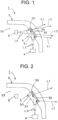
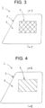
- FIG. 1 to FIG. 8 illustrate a first embodiment of a vehicle lamp according to the present invention. The following is a description of a configuration of the vehicle lamp of the first embodiment.
- a reference sign 1 denotes the vehicle lamp of the first embodiment.
- the vehicle lamp 1 is, in this example, a tail stop lamp that constitutes a rear combination lamp.
- the vehicle lamp 1 may be a stop lamp or a tail lamp, in addition to a tail stop lamp.
- the vehicle lamp 1 is mounted on each of left and right sides of a rear portion of a vehicle (not illustrated).
- the vehicle lamp 1 includes a lamp housing 2, a lamp lens 3, an excitation light source 4, a luminescence unit 5, and an additional light source 6.
- the lamp housing 2 (see a two-dot chain line in FIG. 8 ) is formed of, for example, a light non-transmitting material (such as a resin member or the like).
- the lamp lens 3 is, for example, a bare outer cover or an outer lens.
- the lamp lens 3 is, in this example, formed of a light-transmitting resin material, such as PMMA, PC, or the like.
- Lamp lens 3 is mounted on the lamp housing 2.
- the lamp housing 2 and the lamp lens 3 form a lamp chamber 23.
- a recess (counterbore) 30 is provided in a portion of an inner surface of the lamp lens 3 (surface facing the lamp chamber 23) where a luminescence unit 5 is fixed.
- the recess 30 is a tool used for positioning and fixing the luminescence unit 5 in a predetermined position in the lamp lens 3.
- a preferred material for the lamp lens 3 is a material with a high transmittance in a visible light range.
- the lamp lens 3 forms red color.
- the lamp lens 3 transmits red light L1 and L2 (see solid arrows in FIG. 1 and FIG. 2 ) and absorbs other light than the red light L1 and L2. That is, the lamp lens 3 is a lens that transmits the photoluminescence L1 as the red light L1 generated in the luminescence unit 5 and emits the photoluminescence L1 outside the lamp chamber 23.
- the excitation light source 4 uses an LED, an LD (semiconductor laser), or the like to emit the excitation light L3 (see dashed arrows in FIG. 1 and FIG. 2 ).
- the excitation light L3 is light with a short wavelength, such as, for example, blue light, violet light, ultraviolet light, or the like.
- the excitation light source 4 is mounted on the lamp housing 2 and is disposed in the lamp chamber 23, as illustrated in FIG. 8 .
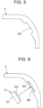
- an optical axis 40 of the excitation light source 4 is inclined at an angle of about 45° to a luminescence surface of the luminescence unit 5 (see a rectangle with a lattice pattern in FIG. 3 and a rectangle with a shaded pattern in FIG. 4 ).
- the optical axis 40 passes center of the luminescence surface of the excitation light source 4 and is perpendicular to the luminescence surface of the excitation light source 4.
- the excitation light source 4 is, in this example, a light source for tail stop lamps.
- the luminescence unit 5 is fixed to the lamp lens 3 on a side thereof closer to the lamp chamber 23 and generates the photoluminescence L1 by the excitation light L3 emitted from the excitation light source 4.
- the luminescence unit 5 includes a luminescence layer 50 and a substrate (support substrate) 51.
- the luminescence layer 50 is formed of an organic luminescence material (organic phosphor material), an inorganic luminescence material (inorganic phosphor material), or the like.
- the luminescence layer 50 generates the photoluminescence L1 by the excitation light L3 emitted from the excitation light source 4.
- the photoluminescence L1 is, in this example, red light L1 with a longer wavelength than that of the excitation light L3.
- the luminescence layer 50 has a rectangular surface shape in this example.
- the vehicle lamp 1 provides rectangular surface luminescence (see a rectangle with the lattice pattern in FIG. 3 and the rectangle with the shaded pattern in FIG. 4 ) by the photoluminescence L1 generated in the luminescence layer 50 having a rectangular surface shape.
- a substrate 51 transmits the excitation light L3 emitted from the excitation light source 4 and the red light L2 emitted from the additional light source 6.
- the substrate 51 is, in this example, formed of a light-transmitting resin material, such as PMMA, PC, or the like, light-transmitting glass, or the like.
- the substrate 51 can be flexible or rigid.
- the substrate 51 has, in this example, a rectangular plate shape in a size one round larger than the luminescence layer 50. On one rectangular surface of the substrate 51, the luminescence layer 50 having a rectangular surface shape is formed (deposited).
- the luminescence unit 5 is positioned and fixed in the recess 30 in the inner surface of the lamp lens 3 by an adhesive 52.
- a luminescence layer 50 faces the lamp lens 3 via the adhesive 52.
- the luminescence layer 50 is fixed to the lamp lens 3 in a sealed state via the adhesive 52. That is, between the luminescence layer 50 and the lamp lens 3, there is the adhesive 52 whose refractive index is larger than a refractive index 1 of air, and air whose refractive index is 1 does not exist.
- the photoluminescence L1 generated in the luminescence layer 50 can enter the lamp lens 3 via the adhesive 52 without air therebetween.
- the substrate 51 faces the excitation light source 4 and the additional light source 6 in the lamp chamber 23.
- One portion of the substrate 51 (a portion thereof on one plate surface side on which the luminescence layer 50 is formed) is fitted in the recess 30 of the lamp lens 3 and is adhered to the adhesive 52.
- the substrate 51 seals the luminescence layer 50 together with the adhesive 52.
- the adhesive 52 transmits the photoluminescence L1 generated in the luminescence layer 50 and the red light L2 emitted from the additional light source 6.
- the adhesive 52 is, in this example, formed of silicone resin, epoxy resin, or the like.
- the refractive index of the adhesive 52 is preferably similar to that of the lamp lens 3.
- An additional light source 6 emits the red light L2.
- the additional light source 6 uses, in this example, an LED, an LD (semiconductor laser), or the like.
- the red light L2 emitted from the additional light source 6 is red light having a wavelength similar to that of the photoluminescence L1.
- the additional light source 6 is mounted on the lamp housing 2 and is disposed in the lamp chamber 23.
- An optical axis 60 of the additional light source 6 is, in this example, about 45° inclined with respect to the luminescence surface of the luminescence unit 5.
- the optical axis 60 of the additional light source 6 and the optical axis 40 of the excitation light source 4 intersect each other at about 90°.
- the optical axis 60 passes the center of the luminescence surface of the additional light source 6 and is perpendicular to the luminescence surface of the additional light source 6.
- the additional light source 6 is, in this example, a light source for stop lamps.
- the lamp housing 2 is molded.
- the lamp lens 3 with the recess 30 is molded (see FIG. 5 ). Furthermore, the luminescence unit 5 is produced.
- the adhesive 52 is applied in the recess 30 of the lamp lens 3 and the luminescence unit 5 is fitted in the recess 30 with the luminescence layer 50 facing the lamp lens 3 (see FIG. 6 ).
- the lamp lens 3 and the luminescence unit 5 are bonded together using the adhesive 52 to produce an integrated structure of the lamp lens 3 and the luminescence unit 5 (see FIG. 7 ).
- the lamp housing 2 and the lamp lens 3 are mounted to form the lamp chamber 23.
- the excitation light source 4 and the additional light source 6 are disposed in the lamp chamber 23.
- the vehicle lamp 1 is assembled (see FIG. 8 ).
- the vehicle lamp 1 of the first embodiment has the configuration described above and an operation thereof will be described below.
- the excitation light source 4 is turned on. Then, the excitation light L3 is emitted from the luminescence surface of the excitation light source 4 toward the luminescence unit 5 to form a Lambertian distribution. The excitation light L3 is transmitted through the substrate 51 of the luminescence unit 5 and is applied to the luminescence layer 50 of the luminescence unit 5.
- the luminescence layer 50 generates the photoluminescence L1 by the excitation light L3.
- the photoluminescence L1 is transmitted through the adhesive 52 and the lamp lens 3 and is emitted outside the vehicle lamp 1 in a predetermined tail lamp light distribution pattern. At this time, the vehicle lamp 1 produces a rectangular surface luminescence with the shaded pattern in FIG. 4 .
- the additional light source 6 is additionally turned on. Then, the red light L2 is additionally emitted from the luminescence surface of the additional light source 6 toward the luminescence unit 5 to form a Lambertian distribution.
- the red light L2 is transmitted through the substrate 51 and the luminescence layer 50 of the luminescence unit 5, the adhesive 52, and the lamp lens 3 and is emitted outside the vehicle lamp 1 in a predetermined stop lamp light distribution pattern.
- the above-described photoluminescence L1 is also transmitted through the adhesive 52 and the lamp lens 3 and is emitted outside the vehicle lamp 1 in a predetermined stop lamp light distribution pattern.
- the vehicle lamp 1 produces a rectangular surface luminescence with the lattice pattern in FIG. 3 .
- the vehicle lamp 1 of the first embodiment has the configuration and the operation described above, and effects thereof will be described below.
- the luminescence unit 5 is fixed to the lamp lens 3 on the side thereof closer to the lamp chamber 23, so that the photoluminescence L1 generated by the excitation light L3 emitted from the excitation light source 4 directly enters the lamp lens 3 without passing through the air (air layer). That is, when the photoluminescence L1 from the luminescence unit 5 enters the lamp lens 3 from the air (air layer), the photoluminescence L1 is not totally reflected at an incident surface of the lamp lens 3.
- the vehicle lamp 1 according to the first embodiment can cause almost all of the photoluminescence L1 from the luminescence unit 5 to enter the lamp lens 3, and therefore, can effectively utilize the photoluminescence L1.
- the luminescence unit 5 is formed of the luminescence layer 50 and the substrate 51 and the luminescence layer 50 is fixed to the lamp lens 3 in a sealed state so as to face the lamp lens 3 via an adhesive 52.
- the vehicle lamp 1 according to the first embodiment can cause almost all of the photoluminescence L1 to enter the lamp lens 3 via the adhesive 52, and thus, can effectively utilize the photoluminescence L1.
- the substrate 51 is formed of a member that transmits the excitation light L3 and the adhesive 52 is formed of a member that transmits the photoluminescence L1, and therefore, can effectively utilize the excitation light L3 and the photoluminescence L1.
- the vehicle lamp 1 according to the first embodiment can accommodate all of the luminescence layer 50 of the luminescence unit 5 and a portion of the substrate 51 in the recess 30 of the lamp lens 3, and therefore, can cause all of the photoluminescence L1 generated in the luminescence layer 50 to enter the lamp lens 3 and can effectively utilize the photoluminescence L1.
- the vehicle lamp 1 of the first embodiment can position and fix the luminescence unit 5 in the recess 30 of the lamp lens 3. As a result, in the vehicle lamp 1 of the first embodiment, accuracy of positioning the luminescence unit 5 is improved, the vehicle lamp 1 according to the first embodiment can control the photoluminescence L1 with high accuracy and can control the light distribution pattern (the tail lamp light distribution pattern and the stop lamp light distribution pattern) formed by emitting of the photoluminescence L1 with high accuracy.
- the photoluminescence L1 is red light and the lamp lens 3 is a lens that transmits red light and absorbs other light than the red light.
- the vehicle lamp 1 of the first embodiment can effectively utilize the red light photoluminescence L1.
- the additional light source 6 that emits the red light L2 is disposed in the lamp chamber 23, and therefore, can effectively utilize both the red light photoluminescence L1 and the red light L2.
- the vehicle lamp 1 according to the first embodiment has two lamp functions, that is, for example, a tail lamp function and a stop lamp function by the red light photoluminescence L1 and the red light L2.
- FIG. 9 and FIG. 10 illustrate a second embodiment of the vehicle lamp of the present invention.
- a configuration, an operation, and effects of a vehicle lamp 1A according to the second embodiment will be described below.
- the same signs as those in FIG. 1 to FIG. 8 indicate the same items.
- the vehicle lamp 1A of the second embodiment is a variant of the vehicle lamp 1 according to the first embodiment described above.
- Each of components of the vehicle lamp 1A of the second embodiment such as a lamp housing (not illustrated), a lamp lens 3, an excitation light source (not illustrated), a luminescence layer 50, a substrate 51,an adhesive 52, an additional light source (not illustrated), or the like, has the same configuration as that of a corresponding one of components of the vehicle lamp 1 of the first embodiment described above, such as the lamp housing 2, the lamp lens 3, the excitation light source 4, the luminescence layer 50, the substrate 51, the adhesive 52, the additional light source 6, or the like.
- the luminescence unit 5 of the vehicle lamp 1 of the first embodiment described above includes the luminescence layer 50 and the substrate 51.
- a luminescence unit 5A of the vehicle lamp 1A of the second embodiment includes the luminescence layer 50, the substrate 51, and sealing members 53 and 54.
- the sealing members 53 and 54 include a sealing substrate 53 and a sealing adhesive 54 that seals and bonds the sealing substrate 53 to the luminescence layer 50.
- the sealing substrate 53 transmits the photoluminescence L1 and the red light L2. Similar to the substrate 51, the sealing substrate 53 is, in this example, formed of a light-transmitting resin material, such as PMMA, PC, or the like, light-transmitting glass, or the like.
- the sealing substrate 53 can be flexible or rigid.
- the sealing substrate 53 has approximately the same size and shape as those of the substrate 51.
- a refractive index of the sealing substrate 53 is preferably the same as that of the lamp lens 3.
- the sealing adhesive 54 transmits the photoluminescence L1 and the red light L2. Similar to the adhesive 52, the sealing adhesive 54 is, in this example, formed of silicone resin, epoxy resin, or the like. A refractive index of the sealing adhesive 54 is preferably the same as those of the sealing substrate 53 and the lamp lens 3.
- a production process for the luminescence unit 5A will be described below with reference to FIG. 9 .
- the substrate 51 is produced (see FIG. 9(A)).
- the luminescence layer 50 is formed (deposited) on the substrate 51 (see FIG. 9(B)).
- the luminescence unit 5 of the vehicle lamp 1 of the first embodiment described above is produced.
- the sealing substrate 53 is produced separately from production of the substrate 51. Thereafter, the luminescence layer 50 and the substrate 51 are bonded to the sealing substrate 53 with the sealing adhesive 54 (see FIG. 9(C)). The luminescence layers 50 is then sealed by the sealing members (the sealing substrate 53 and the sealing adhesive 54) (see FIG. 9 (D)).
- the luminescence unit 5A of the vehicle lamp 1A of the second embodiment is produced.
- the luminescence layer 50 faces the sealing substrate 53 via the sealing adhesive 54.
- a portion of the substrate 51 (peripheral portions of the luminescence layer 50 located around four sides thereof) is bonded to the sealing adhesive 54.
- the luminescence unit 5A produced by the production process described above is fixed to the lamp lens 3 on a side thereof closer to the lamp chamber 23 via the adhesive 52.
- the luminescence unit 5A is fixed in the recess 30 of the lamp lens 3 via the adhesive 52.
- the luminescence unit 5A is fixed to a surface of the lamp lens 3 on the side thereof closer to the lamp chamber 23 via the adhesive 52.
- the sealing members face the lamp lens 3.
- the vehicle lamp 1A of the second embodiment has the configuration described above, and therefore, can achieve similar operation and effects to those of the vehicle lamp 1 of the first embodiment described above.
- the luminescence layer 50 can be sealed and protected by the sealing members (the sealing substrate 53 and the sealing adhesive 54).
- FIG. 11 to FIG. 13 illustrate a third embodiment of the vehicle lamp of the present invention.
- a configuration of a vehicle lamp 1B according to the third embodiment will be described below.
- the same signs as those in FIG. 1 to FIG. 10 indicate the same items.
- the vehicle lamp 1B of the third embodiment is almost the same as the vehicle lamps 1 and 1A of the first and second embodiments described above and includes a lamp housing (not illustrated), a lamp lens 3, an excitation light source 4, and a luminescence unit 5B.
- a corresponding one of the luminescence units 5 and 5A is fixed to the lamp lens 3.
- the luminescence unit 5B is not fixed to the lamp lens 3 but is disposed in the lamp chamber 23.
- excitation light sources 4 are mounted on a bottom surface of a mounting part 41 so as to be spaced at equal intervals. Luminescence surfaces of the excitation light sources 4 face downward. There is no particular limitation on the number of excitation light sources 4.
- a luminescence unit 5B is disposed under the excitation light sources 4.
- the luminescence unit 5B includes a luminescence layer 50B, a substrate 51B, a sealing substrate 53B, a sealing adhesive 54B, a first light emitting part 531, and a second light emitting part 532.
- Components of the luminescence unit 5B of the third embodiment that is, the luminescence layer 50B, the substrate 51B, the sealing substrate 53B, and the sealing adhesive 54B are made of the same materials as those used for components of the luminescence units 5 and 5A of the first and second embodiments described above, that is, the luminescence layer 50, the substrate 51, the sealing substrate 53, and the sealing adhesive 54.
- the substrate 51B, the sealing substrate 53B, and the sealing adhesive 54B transmit the photoluminescence L1 from the luminescence layer 50B and the excitation light L3 from the excitation light sources 4.
- the substrate 51B and the sealing substrate 53B have a light guide function of guiding the photoluminescence L1 by a total reflection action.
- the luminescence layer 50B has a rectangular surface shape that is long in a left-right direction in this example.
- each of the substrate 51B and the sealing substrate 53B has a rectangular plate shape in a size one round larger than that of the luminescence layer 50B and a dimension thereof in an up-down direction is twice as large as that of the luminescence layer 50B or more.
- the luminescence layer 50B is formed (deposited) on an upper portion of one surface of the substrate 51B.
- a recess 530 is provided so as to correspond to the luminescence layer 50B in the upper portion of the one surface of the sealing substrate 53B (a surface facing the luminescence layer 50B and the substrate 51B).
- the first light emitting part 531 is provided in an upper portion of the other surface of the sealing substrate 53B.
- the first light emitting part 531 and the recess 530 are provided in the both surfaces of the sealing substrate 53B so as to mutually correspond.
- the first light emitting part 531 has a rectangular surface shape that is long in the left-right direction.
- the first light emitting part 531 emits the photoluminescence L1 that has been transmitted through the sealing substrate 53B (substrate) outside the sealing substrate 53B (substrate).
- a plurality of second light emitting parts 532 that is, three second light emitting parts 532 in this example, are provided in a lower portion of the other surface of the sealing substrate 53B.
- Each of the second light emitting parts 532 has a circular shape and protrudes from the other surface of the sealing substrate 53B.
- the second light emitting parts 532 emit the photoluminescence L1 that is totally reflected in the sealing substrate 53B (substrate) outside the sealing substrate 53B (substrate).
- a production process for the luminescence unit 5B will be described below with reference to FIG. 13 .
- the substrate 51B is produced (see FIG. 13(A)).
- the luminescence layer 50B is formed (deposited) on the upper portion of the one surface of the substrate 51B (see FIG. 13(B)).
- the sealing substrate 53B is produced separately from production of the substrate 51B. Thereafter, one surface of the luminescence layer 50B and one surface of the substrate 51B are bonded to one side of the sealing substrate 53B using the sealing adhesive 54 (see FIG. 13(C)). Then, the luminescence layer 50B is sealed by the substrate 51B, the sealing substrate 53B, and the sealing adhesive 54B (see FIG. 13(D)).
- the luminescence unit 5B of the vehicle lamp 1B of the third embodiment is produced.
- the luminescence layer 50B faces the sealing substrate 53B via the sealing adhesive 54B.
- a portion of the substrate 51B other than the luminescence layer 50B is bonded to the sealing substrate 53B via the sealing adhesive 54B.
- the luminescence unit 5B produced by the production process described above is disposed under the excitation light sources 4 in the lamp chamber 23 of the vehicle lamp 1B.
- the upper end surface of the luminescence unit 5B faces the luminescence surfaces of the excitation light sources 4.
- the first light emitting part 531 and the second light emitting part 532 of the luminescence unit 5B face the lamp lens 3.
- the excitation light sources 4 may be disposed on at least one of left and right end surfaces of the luminescence unit 5B.
- the excitation light sources 4 can be disposed so as to be inclined with respect to the luminescence unit 5B on a side closer to the lamp lens 3 or an opposite side to the lamp lens 3.
- the vehicle lamp 1B of the third embodiment has the configuration described above and an operation thereof will be described below.
- the excitation light sources 4 are turned on. Then, the excitation light L3 is emitted from the luminescence surfaces of the excitation light sources 4 toward the luminescence unit 5B to form a Lambertian distribution.
- the excitation light L3 enters the substrate 51B, the sealing substrate 53B, and the sealing adhesive 54B from an upper end surface of the luminescence unit 5, is transmitted through the substrate 51B, the sealing substrate 53B, and the sealing adhesive 54B, and is applied to the luminescence layer 50B.
- the luminescence layer 50B generates the photoluminescence L1 by the excitation light L3. A portion of the photoluminescence L1 is transmitted through the sealing adhesive 54B and the sealing substrate 53B and is emitted outside the sealing substrate 53B from the first light emitting part 531.
- a large portion of the remaining photoluminescence L1 is totally reflected at the other surface of the substrate 51B and the other surface of the sealing substrate 53B, is transmitted through the substrate 51B, the sealing substrate 53B, and the sealing adhesive 54B, and is emitted outside the sealing substrate 53B from the second light emitting part 532.
- the photoluminescence L1 emitted outside the sealing substrate 53B from the first light emitting part 531 and the second light emitting part 532 is transmitted through the lamp lens 3 and is emitted outside the vehicle lamp 1B with a predetermined tail lamp light distribution pattern or a predetermined stop lamp light distribution pattern.
- the vehicle lamp 1B achieves surface luminescence having a rectangular shape that is long in the left-right direction in the first light emitting part 531 (see FIG. 11 ) and three surface luminescence each having a circular shape in the second light emitting part 532 (see FIG. 11 ).
- the vehicle lamp 1B of the third embodiment has the configuration and the operation described above, and effects thereof will be described below.
- the first light emitting part 531 and the second light emitting parts 532 are provided on the sealing substrate 53B (substrate).
- the vehicle lamp 1B of the third embodiment can emit a portion of the photoluminescence L1 that has been transmitted through the sealing adhesive 54B and the sealing substrate 53B (substrate) directly from the luminescence layer 50B outside the sealing substrate 53B (substrate) from the first light emitting part 531.
- the vehicle lamp 1B of the third embodiment can transmit a large portion of the remaining photoluminescence L1, that is, the photoluminescence L1 that has not been emitted outside the sealing substrate 53B (substrate) from the first light emitting part 531, through the substrate 51B, the sealing substrate 53B, and the sealing adhesive 54B and emit the portion of the photoluminescence L1 outside the sealing substrate 53B (substrate) from the second light emitting part 532, while totally reflecting the portion of the photoluminescence L1 on the other surface of the substrate 51B and the other surface of the sealing substrate 53B.
- the vehicle lamp 1B of the third embodiment can more effectively utilize the photoluminescence L1.
- the photoluminescence L1 is red light and the lamp lens 3 is a lens (red lens) that transmits red light and absorbs other light than the red light.
- the vehicle lamp 1B of the third embodiment can effectively utilize the red light photoluminescence L1.
- FIG. 14 and FIG. 15 illustrate a fourth embodiment of the vehicle lamp of the present invention.
- a configuration, an operation, and effects of a vehicle lamp 1C according to the fourth embodiment will be described below.
- the same signs as those in FIG. 1 to FIG. 13 indicate the same items.
- the vehicle lamp 1C of the fourth embodiment is a variant of the vehicle lamp 1B of the third embodiment described above.
- Each of components of the vehicle lamp 1C of the fourth embodiment such as, a lamp housing (not illustrated),an excitation light source 4, a luminescence unit 5C (a luminescence layer 50C, a substrate 51C, a sealing substrate 53C), or the like, has the same configuration as that of a corresponding one of components of the vehicle lamp 1B of the third embodiment described above, such as the lamp housing, the excitation light source 4, the luminescence unit 5B (the luminescence layer 50B, the substrate 51B, and the sealing substrate 53B), or the like.
- the vehicle lamp 1B of the third embodiment described above uses a lens (red lens) that transmits red light and absorbs other light than the red light as the lamp lens 3.
- the vehicle lamp 1C of the fourth embodiment uses a colorless transparent lens as the lamp lens 3C.
- a light shielding member 55C is disposed between the lamp lens 3C and a first light emitting part 531 of the luminescence unit 5C.
- the light shielding member 55C shields light including the photoluminescence L1 that is red light.
- the vehicle lamp 1C of the fourth embodiment has the configuration described above, and therefore, can achieve similar operation and effects to those of the vehicle lamp 1B of the third embodiment described above.
- the vehicle lamp 1C of the fourth embodiment uses a colorless transparent lens as the lamp lens 3C, and therefore, inside of the lamp chamber 23 can be seen from outside of the vehicle lamp 1C through the lamp lens 3C and a portion of a second light emitting part 532 of the luminescence unit 5C when light is not on. When light is on, three circles of surface luminescence of the second light emitting part 532 of luminescence unit 5C can be seen.
- the vehicle lamp 1C of the fourth embodiment can achieve a nearly transparent design when light is not on and also can achieve a luminescence surface having an arbitrary design when light is on.
- FIG. 16 and FIG. 17 illustrate a fifth embodiment of the vehicle lamp of the present invention.
- a configuration, an operation, and effects of a vehicle lamp 1D according to the fifth embodiment will be described below.
- the same signs as those in FIG. 1 to FIG. 15 indicate the same items.
- the vehicle lamp 1D of the fifth embodiment is a variant of the vehicle lamp 1B of the third embodiment described above.
- Each of components of the vehicle lamp 1D of the fifth embodiment such as, a lamp housing (not illustrated), a lamp lens 3, an excitation light source 4, a luminescence unit 5D (a luminescence layer 50D, a substrate 51D, a sealing substrate 53D), or the like, has the same configuration as that of a corresponding one of components of the vehicle lamp 1B of the third embodiment, such as the lamp housing, the lamp lens 3, the excitation light source 4, the luminescence unit 5B (the luminescence layer 50B, the substrate 51B, and the sealing substrate 53B), or the like.
- the vehicle lamp 1D of the fifth embodiment includes a reflector 56D.
- the reflector 56D is disposed so as to face an end surface (lower end surface) of a portion of the substrate (that is, the substrate 51D and the sealing substrate 53D) of the luminescence unit 5D located closer to the second light emitting part 532.
- a luminescence surface of the excitation light source 4 faces an end surface (upper end surface) of a portion of the substrate (that is, the substrate 51D and the sealing substrate 53D) of the luminescence unit 5D located closer to the first light emitting part 531.
- the excitation light source 4 and the reflector 56D are vertically disposed with the luminescence unit 5D interposed therebetween.
- a reflective surface 560 is provided in an inner surface of the reflector 56D.
- the reflective surface 560 faces each of the end surface of the substrate of the luminescence unit 5D located closer to the second light emitting part 532 and an inner surface of the lamp lens 3 (a surface of the lamp lens 3 located closer to the lamp chamber 23).
- the reflective surface 560 reflects the photoluminescence L1 that has been totally reflected in the substrate of the luminescence unit 5D and has been emitted to outside from the end surface of the substrate located closer to the second light emitting part 532 toward the lamp lens 3.
- the vehicle lamp 1D of the fifth embodiment has the configuration described above, and therefore, can achieve similar operation and effects to those of the vehicle lamps 1B and 1C of the third and fourth embodiments described above.
- the vehicle lamp 1D of the fifth embodiment includes the reflector 56D having the reflective surface 560.
- the vehicle lamp 1D of the fifth embodiment can reflect the photoluminescence L1 that has been totally reflected in the substrate of the luminescence unit 5D and has been emitted outside from the end surface of the substrate located closer to the second light emitting part 532 toward the lamp lens 3 by the reflective surface 560 of the reflector 56D.
- the vehicle lamp 1D of the fifth embodiment can more effectively utilize the photoluminescence L1.
- the vehicle lamp 1D of the fifth embodiment emits the photoluminescence L1 that has been transmitted directly through the substrate from the luminescence layer 50B outside the substrate from the first light emitting part 531, transmits the photoluminescence L1 that has not been emitted outside the substrate from the first light emitting part 531 through the substrate while totally reflecting the photoluminescence L1 in the substrate to emit the photoluminescence L1 outside the substrate from the second light emitting part 532, and further transmits the photoluminescence L1 that has not been emitted outside the substrate from the second light emitting part 532 through the substrate while totally reflecting the photoluminescence L1 in the substrate to emit the photoluminescence L1 outside the substrate from the lower end surface of the substrate.
- the vehicle lamp 1D of the fifth embodiment can more effectively utilize the photoluminescence L1.
- FIG. 18 and FIG. 19 illustrate a sixth embodiment of the vehicle lamp of the present invention.
- a configuration, an operation, and effects of a vehicle lamp 1E according to the sixth embodiment will be described below.
- FIG. 18 and FIG. 19 the same signs as in FIG. 1 to FIG. 17 indicate the same items.
- the vehicle lamp 1E of the sixth embodiment is a variant of the vehicle lamp 1B of the third embodiment described above.
- Each of components of the vehicle lamp 1E of the sixth embodiment such as, a lamp housing (not illustrated), a lamp lens 3, an excitation light source 4, a luminescence unit 5E (a luminescence layer 50E, a substrate 51E, a sealing substrate 53E), or the like, has the same configuration as that of a corresponding one of components of the vehicle lamp 1B of the third embodiment described above, such as the lamp housing, the lamp lens 3, the excitation light source 4, the luminescence unit 5B (the luminescence layer 50B, the substrate 51B, and the sealing substrate 53B), or the like.
- the vehicle lamp 1E of the sixth embodiment is vertically symmetrical with respect to a straight line connecting the three second light emitting parts 532 in the vehicle lamp 1B of the third embodiment described above. That is, the excitation light sources 4 are above and under the luminescence unit 5E, respectively.
- the luminescence layer 50E and the first light emitting part 531 are disposed vertically symmetrically with respect to the straight line connecting the three second light emitting parts 532.
- the vehicle lamp 1E of the sixth embodiment has the configuration described above, and therefore, can achieve similar operation and effects to those of the vehicle lamp 1B of the third embodiment described above.
- the excitation light sources 4, the luminescence layer 50E, and the first light emitting part 531 are disposed vertically symmetrically with respect to the straight line connecting the three second light emitting parts 532.
- the vehicle lamp 1E of the sixth embodiment can achieve a luminescence surface having a large area.
- FIG. 20 illustrates a seventh embodiment of the vehicle lamp of the present invention.
- a configuration of a vehicle lamp 1F according to the seventh embodiment will be described below.
- the same signs as those in FIG. 1 to FIG. 19 indicate the same items.
- the vehicle lamp 1F of the seventh embodiment is almost the same as the vehicle lamps 1 and 1B of the first and third embodiments described above and includes a lamp housing (not illustrated), a lamp lens (not illustrated), an excitation light source 4, and a luminescence unit 5F.
- Each of the vehicle lamps 1 and 1B of the first and third embodiments described above causes the excitation light L3 that has been emitted from a luminescence surface of the excitation light source 4 to form a Lambertian distribution to enter a corresponding one of the luminescence units 5 and 5B as it is and applies the excitation light L3 to the corresponding one of the luminescence layers 50 and 50B as it is.
- the vehicle lamp 1F of the seventh embodiment causes the luminescence unit 5F to control the excitation light L3 from the excitation light source 4 to cause the excitation light L3 to enter there and causes a luminescence layer 50F to control the excitation light L3 to emit the excitation light L3.
- the luminescence unit 5F includes the luminescence layer 50F and a substrate 51F. Similar to the luminescence units 5A and 5B of the second and third embodiments described above, the luminescence unit 5F of the seventh embodiment may be configured such that the luminescence layer 50F is sealed by a sealing substrate (not illustrated) and a sealing adhesive (not illustrated).
- Components of the luminescence unit 5F of the seventh embodiment that is, the luminescence layer 50F and the substrate 51F are made of the same materials as those used for components of the luminescence units 5 and 5B of the first and third embodiments, that is, the luminescence layers 50 and 50B and the substrates 51 and 51B.
- the luminescence layer 50F is disposed so as to face the lamp lens in a lamp chamber (not illustrated).
- the substrate 51F includes a first incident surface 571, a second incident surface 572, a first reflective surface 573, a second reflective surface 574, and a light emitting surface 570.
- the first incident surface 571 is a surface on which the excitation light L3 from the excitation light source 4 (the excitation light L3 whose solid angle including center of the luminescence surface of the excitation light source 4 serving as a point (a vertex of the angle) is about 70° to 80°) is refracted to enter the surface as parallel first incident light.
- the first incident light is parallel to an optical axis of the excitation light source 4 (which will be hereinafter referred to as an "optical axis").
- the first incident surface 571 is provided so as to be opposed to the luminescence surface of the excitation light source 4.
- the first incident surface 571 is a refractive surface of a rotational hyperboloid generated by rotating a hyperbola including the center of the luminescence surface as a focal point around a main axis of the hyperbola (optical axis) as a rotation shaft.
- the second incident surface 572 is a surface on which the excitation light L3 from the excitation light source 4 (the excitation light L3 whose solid angle including the center of the luminescence surface of the excitation light source 4 serving as a point (a vertex of the angle) is about 70° to 80° to about 180°) is refracted to enter the surface as second incident light.
- the second incident surface 572 is an outer periphery of the first incident surface 571 and is provided so as to be opposed to the luminescence surface of the excitation light source 4.
- the second incident surface 572 is a refractive surface of a rotating surface generated by rotating a straight line or a curved line around the optical axis as a rotation shaft.
- the first reflective surface 573 is a surface that totally reflects the second incident light (a portion of incident light) from the second incident surface 572 as the first reflection light that is parallel to the optical axis.
- the first reflective surface 573 is a reflective surface of a paraboloid of revolution generated by rotating a parabola including the center of the luminescence surface of the excitation light source 4 as a focal point around the optical axis as a rotation shaft.
- the first reflective surface 573 is a reflective surface of a rotating surface generated by rotating a straight line following the parabola around the optical axis as a rotation shaft.
- the second reflective surface 574 is a surface that totally reflects the first incident light (a portion of the incident light) that is parallel to the optical axis of light that has entered from the first incident surface 571 and the first reflective light that is parallel to the optical axis of light totally reflected by the first reflective surface 573, that is, the second incident light (a portion of the incident light) that has entered from the second incident surface 572, as the second reflective lights that are perpendicular to the optical axis and are mutually parallel.
- the second reflective surface 574 is a multi-stage, that is, in this example, five-stage, flat reflective surface.
- the light emitting surface 570 is a flat surface that emits the second reflective lights reflected from the second reflective surface 547 as emission lights that are perpendicular to the optical axis and are mutually parallel.
- the luminescence layer 50F is formed (deposited) on the light emitting surface 570. As a result, emission light (the excitation light L3 from the excitation light source 4) emitted from the light emitting surface 570 is applied to the luminescence layer 50F. Thus, the luminescence layer 50F emits the photoluminescence L1.
- a mounting part 575 is integrally provided in a portion of the substrate 51F in an opposite side to the light emitting surface 570.
- the mounting part 575 has a mounting hole 576.
- the mounting part 575 is mounted on the lamp housing by a screw or the like (not illustrated) passing through the mounting hole 576 directly or indirectly via a bracket or the like.
- the luminescence unit 5F is mounted on the lamp housing by the mounting part 575 of the substrate 51F directly or indirectly.
- the vehicle lamp 1F of the seventh embodiment has the configuration described above and an operation thereof will be described below.
- the excitation light source 4 is turned on. Then, the excitation light L3 is emitted from the luminescence surface of the excitation light source 4 toward the first incident surface 571 and the second incident surface 572 of the luminescence unit 5F to form a Lambertian distribution.
- a portion of the excitation light L3 enters the substrate 51F as the first incident light parallel to the optical axis from the first incident surface 571.
- a remaining portion of the excitation light L3 enters the substrate 51F from the second incident surface 572 as the second incident light and is reflected as the first reflection light that is parallel to the optical axis at the first reflective surface 573.
- the first incident light that is parallel to the optical axis and the first reflection light are totally reflected as the second reflection lights that are perpendicular to the optical axis on the second reflective surface 574 and are mutually parallel.
- the second reflection lights are emitted from the light emitting surface 570 as emission lights and are applied to the luminescence layer 50F.
- the luminescence layer 50F emits the photoluminescence L1 toward the lamp lens.
- the photoluminescence L1 is transmitted through the lamp lens and is emitted outside the vehicle lamp 1F in a predetermined light distribution pattern.
- the vehicle lamp 1F of the seventh embodiment has the configuration described above and effects thereof will be described below.
- the vehicle lamp 1F of the seventh embodiment the first incident surface 571, the second incident surface 572, the first reflective surface 573, the second reflective surface 574, and the light emitting surface 570 are provided on the substrate 51F of the luminescence unit 5F.
- the vehicle lamp 1F of the seventh embodiment can cause the luminescence unit 5F to control the excitation light L3 from the excitation light source 4 as parallel light (the parallel excitation light L3) to cause the excitation light L3 to enter there and also cause the luminescence layer 50F to control the excitation light L3 as parallel light (the parallel excitation light L3) to emit the excitation light L3.
- the vehicle lamp 1F of the seventh embodiment can control the photoluminescence L1 to emit the photoluminescence L1 from the luminescence layer 50F, and moreover, can effectively utilize the photoluminescence L1.
- the mounting part 575 is provided on the substrate 51F, and therefore, the luminescence unit 5F can be mounted directly or indirectly on the lamp housing by mounting the mounting part 575 of the substrate 51F directly or indirectly on the lamp housing.
- the vehicle lamp 1F of the seventh embodiment can maintain a relative positional relationship between the lamp lens, the excitation light source 4, and the luminescence unit 5F with high accuracy, and therefore, can reliably cause the excitation light L3 from the excitation light source 4 to enter the luminescence unit 5F and can reliably emit the photoluminescence L1 from the luminescence unit 5F toward the lamp lens.
- the vehicle lamp 1F of the seventh embodiment can reliably control the photoluminescence L1 from the luminescence unit 5F, and moreover, can more effectively utilize the photoluminescence L1.
- the luminescence layer 50F is formed to have a reduced thickness as indicated by the solid line, red color of the photoluminescence L1 becomes lighter, and if the luminescence layer 50F is formed to have an increased thickness as indicated by the double-dotted chain line, the red color of the photoluminescence L1 becomes darker. This is also true for the vehicle lamps 1 to 1E of the first to sixth embodiments described above and the shading of the red color of the photoluminescence L1 can be adjusted in the vehicle lamps 1 to 1E.
- the photoluminescence L1 is red light and the lamp lens 3 is a lens (red lens) that transmits red light and absorbs other light than the red light.
- the vehicle lamp 1B of the third embodiment can effectively utilize the red light photoluminescence L1.
- FIG. 21 and FIG. 22 illustrate an eighth embodiment of the vehicle lamp of the present invention.
- a configuration of a vehicle lamp 1G according to the embodiment 8 will be described below.
- the same sings as those in FIG. 1 to FIG. 20 indicate the same items.
- the vehicle lamp 1G of the eighth embodiment includes a lamp housing (not illustrated), a lamp lens 3G, and an excitation light source 4.
- Each of the vehicle lamps 1 to 1F of the first to seventh embodiments described above includes a corresponding one of the luminescence units 5 to 5F each of which is provided separately from a corresponding one of the lamp lenses 3 and 3C.
- the vehicle lamp 1G in the eighth embodiment causes the lamp lens 3G to also serve as a luminescence unit.
- the vehicle lamp 1G in the eighth embodiment does not include a luminescence unit.
- the lamp lens 3G forms the lamp chamber 23 together with the lamp housing.
- An excitation light source 4 is disposed in a lamp chamber 23.
- the lamp lens 3G has a lens material 58 and a phosphor material 580.
- the lens material 58 is an ordinary red lens of a resin material, such as, for example, PMMA or the like, containing a red colorant.
- the phosphor material 580 is a red inorganic phosphor material, that is, for example, CASN or the like.
- the lamp lens 3G is formed (molded) by mixing the lens material 58 and the phosphor material 580 during injection forming (injection molding).
- the phosphor material 580 has a particle shape, is contained in the lens material 58, and generates the photoluminescence L1 by the excitation light L3 emitted from the excitation light source 4.
- a transmittance of the lamp lens 3G is 1% or more and less than 100%.
- a weight ratio of the phosphor material 580 in the lamp lens 3G is more than 0% and 50% or less.
- a thickness of the lamp lens 3G is more than 0 mm and 5 mm or less.
- the transmittance of the lamp lens 3G, the weight ratio of the phosphor material 580 of the lamp lens 3G, and the thickness of the lamp lens 3G are not limited to the values in this example.
- the vehicle lamp 1G of the eighth embodiment has the configuration described above and an operation thereof will be described below.
- the excitation light source 4 is turned on. Then, the excitation light L3 is emitted from a luminescence surface of the excitation light source 4 toward the lamp lens 3G.
- the excitation light L3 enters the lamp lens 3G from an inner surface of the lamp lens 3G (a surface thereof located closer to the lamp chamber 23).
- the excitation light L3 that has entered the lamp lens 3G is applied to the phosphor material 580 contained in the lens material 58.
- the phosphor material 580 generates the photoluminescence L1 by the excitation light L3.
- the photoluminescence L1 is transmitted through the lens material 58 and emitted outside the vehicle lamp 1G from an outer surface of the lamp lens 3G (a surface thereof on an opposite side to the lamp chamber 23) in a predetermined light distribution pattern.
- the entire outer surface of the lamp lens 3G emits red light over.
- the vehicle lamp 1G of the eighth embodiment has the configuration described above and effects thereof will be described below.
- the lamp lens 3G includes the lens material 58 and the phosphor material 580, and therefore, the entire lamp lens 3G emits light due to the photoluminescence L1 when the lamp lens 3G is irradiated with the excitation light L3 from the excitation light source 4. As a result, the vehicle lamp 1G of the eighth embodiment can efficiently utilize the photoluminescence L1.
- the vehicle lamp 1G of the eighth embodiment includes the lamp lens 3G, and thus, can emit the photoluminescence L1 without any one of the luminescence units 5 to 5F provided therein.
- the number of components can be reduced and production cost can be cut.
- the phosphor material 580 of the lamp lens 3G is an inorganic phosphor material, so that the phosphor material 580 can be sufficiently resistant to temperature during injection forming of the lamp lens 3G.
- the lens material 58 of the lamp lens 3G is an ordinary red lens of a resin material, such as, for example, PMMA or the like, containing a red colorant
- the phosphor material 580 of the lamp lens 3G is a red inorganic phosphor material, such as, for example, CASN or the like.
- the transmittance of the lamp lens 3G is 1% or more and less than 100%, so that the transmittance of the lamp lens 3G can be adjusted as desired and the degree of design freedom of the lamp lens 3G is increased.
- the weight ratio of the phosphor material 580 in the lamp lens 3G is more than 0% and 50% or less, so that the weight ratio of the phosphor material 580 can be adjusted as desired, an amount of the photoluminescence L1 to be generated can be adjusted, and the degree of design freedom of the photoluminescence L1 is increased.
- the lamp lens 3G has a thickness of more than 0 mm and 5 mm or less, so that the thickness of the lamp lens 3G can be adjusted as desired, the absorption of the excitation light L3 in the lamp lens 3G can be adjusted, and emitting of the excitation light L3 from the lamp lens 3G outside the vehicle lamp 1G can be controlled.
- FIG. 23 illustrates a ninth embodiment of the vehicle lamp of the present invention.
- a configuration, an operation, and effects of a vehicle lamp 1H according to the ninth embodiment will be described below.
- the same signs as in FIG. 1 to FIG. 22 indicate the same items.
- the vehicle lamp 1H of the ninth embodiment is a variant of the vehicle lamp 1G of the eighth embodiment described above.
- Each of components of the vehicle lamp 1H of the ninth embodiment such as a lamp housing (not illustrated), a lamp lens 3H, an excitation light source 4, or the like, has the same configuration as that of a corresponding one of components of the vehicle lamp 1G of the eighth embodiment described above, such as the lamp housing, the lamp lens 3G, the excitation light source 4, or the like.
- an optical member 8 is disposed between the lamp lens 3H and the excitation light source 4 in a lamp chamber 23.
- the optical member 8 controls the excitation light L3 emitted from the excitation light source 4 and applies the excitation light L3 to the lamp lens 3H.
- the optical member 8 has a first incident surface 81, a second incident surface 82, and a light emitting surface 80.
- the first incident surface 81 causes a portion of the excitation light L3 from the excitation light source 4 to enter the optical member 8 as parallel light.
- the second incident surface 82 causes a remaining portion of the excitation light L3 from the excitation light source 4 to enter the optical member 8 as parallel light.
- Parallel incident light from the first incident surface 81 and parallel incident light from the second incident surface 82 are mutually parallel.
- the light emitting surface 80 emits the parallel incident light in the optical member 8 toward the lamp lens 3H as parallel light.
- the vehicle lamp 1H of the ninth embodiment has the configuration described above, and therefore, can achieve similar operation and effects to those of the vehicle lamp 1G of the eighth embodiment described above.
- the optical member 8 is disposed between the lamp lens 3H and the excitation light source 4, so that the excitation light L3 emitted from the excitation light source 4 to form a Lambertian distribution can be controlled as parallel light via the optical member 8 and can be emitted toward the lamp lens 3H.
- the vehicle lamp 1H of the ninth embodiment can efficiently achieve the photoluminescence L1 as parallel light from the lamp lens 3H.
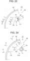
- FIG. 24 and FIG. 25 illustrate a tenth embodiment of the vehicle lamp of the present invention.
- a configuration, an operation, and effects of a vehicle lamp 1I according to the tenth embodiment will be described below.
- FIG. 24 and FIG. 25 the same signs as in FIG. 1 to FIG. 23 indicate the same items.
- the vehicle lamp 1I of the tenth embodiment is a variant of the vehicle lamp 1G of the eighth embodiment described above.
- Each of components of the vehicle lamp 1I of the tenth embodiment such as a lamp housing (not illustrated), a lamp lens 31, an excitation light source 4, or the like, has the same configuration as that of a corresponding one of components of the vehicle lamp 1G of the eighth embodiment described above, such as the lamp housing, the lamp lens 3G, the excitation light source 4, or the like.
- an optical member 7 is disposed between the lamp lens 31 and the excitation light source 4 in a lamp chamber 23.
- the optical member 7 controls the excitation light L3 emitted from the excitation light source 4 and applies the excitation light L3 to the lamp lens 3I.
- the optical member 7 is a light guide member (light guide) having a round-bar shape.
- the optical member 7 has an incident surface 70 on one end surface, a reflective surface 71 on one side surface, and a light emitting surface 72 on the other side surface.
- the incident surface 70 causes the excitation light L3 from the excitation light source 4 to enter the optical member 7.
- the reflective surface 71 reflects the excitation light L 3 that has entered the optical member 7 and is guided from the incident surface at one end surface to the other end surface by the total reflection action in the optical member 7.
- Several reflective surfaces 71 are provided so that the reflective surfaces 71 and stepped surfaces are alternately provided.
- One reflective surface 71 and one stepped surface form one prismatic surface.
- the light emitting surface 72 emits the excitation light L3 in the optical member 8 reflected by the reflective surface 71 as diffused light toward the lamp lens 3I.
- the vehicle lamp 1I of the tenth embodiment has the configuration described above, and therefore, can achieve similar operation and effects to those of the vehicle lamp 1G of the eighth embodiment described above.
- the optical member 7 is disposed between the lamp lens 31 and the excitation light source 4, and therefore, the excitation light L3 emitted from the excitation light source 4 to form a Lambertian distribution can be controlled as diffuse light via the optical member 7 and can be emitted toward the lamp lens 31.
- the vehicle lamp 1I of the tenth embodiment can efficiently achieve the photoluminescence L1 as diffused light from the lamp lens 3I.
- the present invention can be also applied to other vehicle lamps than the lamps or displays described above.
- the present invention can be applied to a turn signal lamp, a rear fog lamp, a backup lamp, or the like provided in a rear portion of a vehicle.
- a rear combination lamp equipped in a rear portion of a vehicle has been described.
- the present invention can be also applied to a front combination lamp, an interior lamp, an instrument lamp, a decorative lamp, a display, or the like equipped in a front portion of a vehicle, in addition to a rear combination lamp equipped in a rear portion of the vehicle.
- the front combination lamp include a headlamp, a fog lamp, a day running lamp, a clearance lamp, a turn signal lamp, or the like.
- the vehicle lamp 1 in which the recess 30 is provided in the lamp lens 3 on the side thereof closer to the lamp chamber 23 has been described.
- a vehicle lamp in which the recess 30 is not provided in the lamp lens 3 on the side thereof closer to the lamp chamber 23 may be employed.
- the first incident surface 571, the second incident surface 572, the first reflective surface 573, and the second reflective surface 574 are provided on the substrate 51F.
- the incident surfaces and the reflective surfaces provided on the substrate there is no particular limitation on the incident surfaces and the reflective surfaces provided on the substrate.
- the excitation light L3 and the photoluminescence L1 are controlled as parallel light.
- control of the excitation light L3 and the photoluminescence L1 is not limited to parallel light.
- the excitation light L3 or the photoluminescence L1 may be controlled as diffused light or convergent (directional) light.
- the transmittance of the lamp lens 3G is 1% or more and less than 100%
- the weight ratio of the phosphor material 580 in the lamp lens 3G is more than 0% and 50% or less
- the thickness of the lamp lens 3G is more than 0 mm and 5 mm or less.
- the transmittance of the lamp lens 3G, the weight ratio of the phosphor material 580 in the lamp lens 3G, and the thickness of the lamp lens 3G are not limited to particular numerical values.
- a red inorganic phosphor material such as for example, CASN or the like
- the phosphor material 580 an inorganic phosphor material is used, but an organic phosphor material may be also used.
- the present invention is not limited by the first to tenth embodiments described above.
- a shape of surface luminescence there is no particular limitation on a shape of surface luminescence. Surface luminescence of any design shape can be achieved.
- a disposition state, the number, or the like of the excitation light sources 4 and the additional light sources 6 to be disposed there is no particular limitation on a disposition state, the number, or the like of the excitation light sources 4 and the additional light sources 6 to be disposed.
Landscapes
- Engineering & Computer Science (AREA)
- General Engineering & Computer Science (AREA)
- Mechanical Engineering (AREA)
- Non-Portable Lighting Devices Or Systems Thereof (AREA)
Abstract
Description
- The present invention relates to a vehicle lamp.
- Examples of a vehicle lamp that uses photoluminescence generated by excitation light emitted from an excitation light source include, for example, a vehicle lamp disclosed in
Patent Literature 1. - The vehicle lamp of
Patent Literature 1 includes an excitation light source that emits excitation light, a luminescence layer that generates photoluminescence by the excitation light emitted from the excitation light source, a holding member that holds the luminescence layer, and a lens member that emits the photoluminescence. - The vehicle lamp of
Patent Literature 1 provides surface luminescence by photoluminescence generated from the luminescence layer. Moreover, since the vehicle lamp ofPatent Literature 1 uses the luminescence layer that does not require electrical energy as a surface light source, reliability of the surface light source is improved as compared to an organic light-emitting diode that requires electrical energy as a surface light source. - PTL 1: International Patent Publication No.
2019/245030 - In such vehicle lamps, it is important to effectively utilize photoluminescence generated by the excitation light emitted from the excitation light source.
- The problem to be solved by the present invention is to provide a vehicle lamp that can effectively utilize photoluminescence generated by excitation light emitted from an excitation light source.
- A vehicle lamp according to the present invention includes a lamp housing and a lamp lens forming a lamp chamber, an excitation light source disposed in the lamp chamber and emitting excitation light, and a luminescence unit fixed to the lamp lens on a side thereof closer to the lamp chamber and generating photoluminescence by the excitation light emitted from the excitation light source, and the lamp lens is a lens that transmits the photoluminescence generated in the luminescence unit and emits the photoluminescence outside the lamp chamber.
- It is preferable that, in the vehicle lamp of the present invention, the luminescence unit includes a luminescence layer that generates the photoluminescence by the excitation light emitted from the excitation light source and a substrate on which the luminescence layer is formed and through which the excitation light is transmitted, the luminescence layer is fixed to the lamp lens by an adhesive so as to face the lamp lens via the adhesive, and the adhesive is a member through which at least the photoluminescence is transmitted.
- It is preferable that, in the vehicle lamp of the present invention, the luminescence unit includes a luminescence layer that generates the photoluminescence by the excitation light emitted from the excitation light source, a substrate on which the luminescence layer is formed and through which the excitation light is transmitted, and a sealing member that seals the luminescence layer, and the luminescence layer is fixed to the lamp lens by an adhesive so as to face the lamp lens via the adhesive and the sealing member, and each of the adhesive and the sealing member is a member through which at least the photoluminescence is transmitted.
- It is preferable that, in the vehicle lamp of the present invention, the sealing member includes a sealing substrate and a sealing adhesive that seals and bonds the sealing substrate to the luminescence layer.
- It is preferable that, in the vehicle lamp of the present invention, a recess in which the luminescence unit is positioned and is fixed is provided in a position where the luminescence unit of the lamp lens is fixed.
- It is preferable that, in the vehicle lamp of the present invention, the photoluminescence is red light, and the lamp lens is a lens that transmits the red light and absorbs other light than the red light.
- It is preferable that, in the vehicle lamp of the present invention, an additional light source that emits red light is disposed in the lamp chamber.
- A vehicle lamp according to the present invention includes a lamp housing and a lamp lens forming a lamp chamber, an excitation light source disposed in the lamp chamber and emitting excitation light, and a luminescence unit disposed in the lamp chamber, the luminescence unit includes a luminescence layer that generates photoluminescence by the excitation light emitted from the excitation light source, a substrate on which the luminescence layer is formed and through which the excitation light and the photoluminescence are transmitted, a first light emitting part provided on the substrate so as to face the lamp lens and emitting the photoluminescence that has been transmitted through the substrate directly outside the substrate from the luminescence layer, and a second light emitting part provided on the substrate so as to face the lamp lens and emitting the photoluminescence that is totally reflected in the substrate outside the substrate.
- It is preferable that, the vehicle lamp of the present invention further includes a reflector, the excitation light source is disposed so as to face an end surface of the substrate located closer to the luminescence layer, and the reflector is disposed so as to face an end surface of the substrate located closer to the second light emitting part and has a reflective surface that reflects the photoluminescence that has been totally reflected in the substrate and has been emitted outside from the substrate toward the lamp lens.
- It is preferable that, in the vehicle lamp of the present invention, the photoluminescence is red light, and the lamp lens is a lens that transmits the red light and absorbs other light than the red light.
- It is preferable that, in the vehicle lamp of the present invention, a light shielding member is disposed between the lamp lens and the first light emitting part, the photoluminescence is a red light, and the lamp lens is a colorless lens.
- A vehicle lamp according to the present invention includes a lamp housing and a lamp lens forming a lamp chamber, an excitation light source disposed in the lamp chamber and emitting excitation light, and a luminescence unit disposed in the lamp chamber, the luminescence unit includes a luminescence layer that generates photoluminescence by the excitation light emitted from the excitation light source, and a substrate on which the luminescence layer is formed and through which the excitation light is transmitted, and the luminescence layer is disposed so as to face the lamp lens, and the substrate has an incident surface that the excitation light emitted from the excitation light source enters and a reflective surface that reflects the excitation light that has entered from the incident surface toward the luminescence layer.
- It is preferable that, in the vehicle lamp of the present invention, the incident surface is an incident surface that the excitation light emitted from the excitation light source enters as parallel incident excitation light, and the reflective surface is a reflective surface that reflects the parallel incident excitation light from the incident surface as parallel reflected excitation light.
- It is preferable that, in the vehicle lamp of the present invention, a mounting part used for mounting the luminescence unit directly or indirectly on the lamp housing is provided on the substrate.
- It is preferable that, in the vehicle lamp of the present invention, the photoluminescence is red light, and the lamp lens is a lens that transmits the red light and absorbs other light than the red light.
- A vehicle lamp according to the present invention includes a lamp housing and a lamp lens forming a lamp chamber, and an excitation light source disposed in the lamp chamber and emitting excitation light, the lamp lens includes a lens material, and a phosphor material contained in the lens material and generating photoluminescence by the excitation light emitted from the excitation light source.
- It is preferable that, in the vehicle lamp of the present invention, an optical member is disposed between the lamp lens and the excitation light source, and the optical member controls the excitation light emitted from the excitation light source and applies the excitation light to the lamp lens.
- It is preferable that, in the vehicle lamp of the present invention, the phosphor material is an inorganic phosphor material.
- It is preferable that, in the vehicle lamp of the present invention, the lens material is a resin material containing a red colorant, and the phosphor material is a red inorganic phosphor material.
- It is preferable that, in the vehicle lamp of the present invention, the transmittance of the lamp lens is 1% or more and less than 100%.
- It is preferable that, in the vehicle lamp of the present invention, a weight ratio of the phosphor material in the lamp lens is more than 0% and 50% or less.
- It is preferable that, in the vehicle lamp of the present invention, a thickness of the lamp lens is more than 0 mm and 5 mm or less.
- A vehicle lamp according to the present invention can effectively utilize photoluminescence generated by excitation light emitted from an excitation light source.
-
- [
FIG. 1] FIG. 1 is a longitudinal cross-sectional view of an excitation light source and an additional light source in a lighting state, illustrating a first embodiment of a vehicle lamp according to the present invention (cross-sectional view taken along a line I-I inFIG. 3 ). - [
FIG. 2] FIG. 2 is a longitudinal cross-sectional view illustrating the lighting state of the excitation light source (cross-sectional view taken along a line II-II inFIG. 4 ). - [
FIG. 3] FIG. 3 is a front view illustrating respective lighting states of the excitation light source and the additional light source. - [
FIG. 4] FIG. 4 is a front view illustrating the lighting state of the excitation light source. - [
FIG. 5] FIG. 5 is a view of a lamp lens. - [
FIG. 6] FIG. 6 is a view illustrating a state before a luminescence unit is fixed to the lamp lens. - [
FIG. 7] FIG. 7 is a view illustrating a state where the luminescence unit fixed to the lamp lens. - [
FIG. 8] FIG. 8 is a view illustrating respective non-lighting states of the excitation light source and the additional light source. - [
FIG. 9] FIG. 9 is a view illustrating a production process of a luminescence unit, illustrating a second embodiment of the vehicle lamp of the present invention. FIG. 9(A) is a view illustrating a substrate. FIG. 9(B) is a view illustrating a state where a luminescence layer is formed on the substrate. - FIG. 9(C) is a view illustrating a state before the substrate and the luminescence layer are adhesively sealed to a sealing substrate with a sealing adhesive. FIG. 9(D) is a view illustrating a state where the substrate and the luminescence layer are adhesively sealed to the sealing substrate with the sealing adhesive (view illustrating a state where the luminescence unit is produced).
- [
FIG. 10] FIG. 10 is a view illustrating a state where the luminescence unit is fixed to the lamp lens. FIG. 10(A) is a view illustrating a state where the luminescence unit is fixed in a recess provided in the lamp lens. FIG. 10(B) is a view illustrating a state where the sealing substrate of the luminescence unit is fixed to an inner surface of the lamp lens. - [
FIG. 11] FIG. 11 is a front view of the excitation light source and the luminescence unit, illustrating a third embodiment of the vehicle lamp of the present invention (view in an arrow direction along an XI-XI line inFIG. 12 ). - [
FIG. 12] FIG. 12 is a longitudinal cross-sectional view illustrating the lamp lens, the excitation light source, and the luminescence unit (cross-sectional view taken along a line XII- XII inFIG. 11 ). - [
FIG. 13] FIG. 13 is a view illustrating a production process of a luminescence unit. FIG. 13(A) is a view illustrating a substrate. FIG. 13(B) is a view illustrating a state where a luminescence layer is formed on the substrate. FIG. 13(C) is a view Illustrating a state before the substrate and the luminescence layer are adhesively sealed to a sealing substrate with a sealing adhesive. FIG. 13(D) is a view illustrating a state where the substrate and the luminescence layer are adhesively sealed to a sealing substrate with a sealing adhesive (view illustrating a state where the luminescence unit is produced). - [
FIG. 14] FIG. 14 is a front view of the excitation light source and the luminescence unit, illustrating a fourth embodiment of the vehicle lamp of the present invention (view in an arrow direction along an XIV-XIV line inFIG. 15 ). - [
FIG. 15] FIG. 15 is a longitudinal cross-sectional view illustrating the lamp lens, the excitation light source, and the luminescence unit (cross-sectional view taken along a line XV-XV inFIG. 16 ). - [
FIG. 16] FIG. 16 is a front view of the excitation light source and the luminescence unit, illustrating a fifth embodiment of the vehicle lamp of the present invention (view in an arrow direction along an XVI-XVI line inFIG. 17 ). - [
FIG. 17] FIG. 17 is a longitudinal cross-sectional view illustrating the lamp lens, the excitation light source, and the luminescence unit (cross-sectional view taken along a line VVII-XVII inFIG. 16 ). - [
FIG. 18] FIG. 18 is a front view of the excitation light source and the luminescence unit, illustrating a sixth embodiment of the vehicle lamp of the present invention (view in an arrow direction along an XVIII-XVIII line inFIG. 19 ). - [
FIG. 19] FIG. 19 is a longitudinal cross-sectional view illustrating a lamp lens, an excitation light source, and a luminescence unit (cross-sectional view taken along a line XIX-XIX inFIG. 18 ). - [
FIG. 20] FIG. 20 is a longitudinal cross-sectional view of the excitation light source and the luminescence unit, illustrating a seventh embodiment of the vehicle lamp of the present invention. - [
FIG. 21] FIG. 21 is a longitudinal cross-sectional view of the lamp lens and the excitation light source, illustrating an eighth embodiment of the vehicle lamp of the present invention. - [
FIG. 22] FIG. 22 is a partially enlarged longitudinal cross-sectional view of a portion of the lamp lens. - [
FIG. 23] FIG. 23 is a longitudinal cross-sectional view of a lamp lens, an excitation light source, and an optical member, illustrating a ninth embodiment of the vehicle lamp of the present invention. - [
FIG. 24] FIG. 24 is a longitudinal cross-sectional view of a lamp lens, an excitation light source, and an optical member, illustrating a tenth embodiment of the vehicle lamp of the present invention. - [
FIG. 25] FIG. 25 is a front view illustrating the excitation light source and the optical member (view in an arrow direction along an XXV-XXV line inFIG. 24 ). - Ten examples of embodiments (examples) of a vehicle lamp according to the present invention will be described in detail below with reference to the accompanying drawings. In this specification, front, rear, up, down, left, and right are front, rear, up, down, left, and right when a vehicle lamp according to the present invention is equipped on a vehicle. Since the drawings are schematic drawings, major components are illustrated and illustration of other components than the major components is omitted. In addition, some hatching of some components is omitted.
-
FIG. 1 to FIG. 8 illustrate a first embodiment of a vehicle lamp according to the present invention. The following is a description of a configuration of the vehicle lamp of the first embodiment. - In
FIG. 1, FIG. 2 ,FIG. 3, FIG. 4 , andFIG. 8 , areference sign 1 denotes the vehicle lamp of the first embodiment. Thevehicle lamp 1 is, in this example, a tail stop lamp that constitutes a rear combination lamp. Thevehicle lamp 1 may be a stop lamp or a tail lamp, in addition to a tail stop lamp. Thevehicle lamp 1 is mounted on each of left and right sides of a rear portion of a vehicle (not illustrated). - The
vehicle lamp 1 includes alamp housing 2, alamp lens 3, anexcitation light source 4, aluminescence unit 5, and an additionallight source 6. - The lamp housing 2 (see a two-dot chain line in
FIG. 8 ) is formed of, for example, a light non-transmitting material (such as a resin member or the like). - The
lamp lens 3 is, for example, a bare outer cover or an outer lens. Thelamp lens 3 is, in this example, formed of a light-transmitting resin material, such as PMMA, PC, or the like. -
Lamp lens 3 is mounted on thelamp housing 2. Thus, thelamp housing 2 and thelamp lens 3 form alamp chamber 23. - A recess (counterbore) 30 is provided in a portion of an inner surface of the lamp lens 3 (surface facing the lamp chamber 23) where a
luminescence unit 5 is fixed. Therecess 30 is a tool used for positioning and fixing theluminescence unit 5 in a predetermined position in thelamp lens 3. - A preferred material for the
lamp lens 3 is a material with a high transmittance in a visible light range. In this example, thelamp lens 3 forms red color. As a result, thelamp lens 3 transmits red light L1 and L2 (see solid arrows inFIG. 1 and FIG. 2 ) and absorbs other light than the red light L1 and L2. That is, thelamp lens 3 is a lens that transmits the photoluminescence L1 as the red light L1 generated in theluminescence unit 5 and emits the photoluminescence L1 outside thelamp chamber 23. - In this example, the
excitation light source 4 uses an LED, an LD (semiconductor laser), or the like to emit the excitation light L3 (see dashed arrows inFIG. 1 and FIG. 2 ). The excitation light L3 is light with a short wavelength, such as, for example, blue light, violet light, ultraviolet light, or the like. - The
excitation light source 4 is mounted on thelamp housing 2 and is disposed in thelamp chamber 23, as illustrated inFIG. 8 . In this example, an optical axis 40 of theexcitation light source 4 is inclined at an angle of about 45° to a luminescence surface of the luminescence unit 5 (see a rectangle with a lattice pattern inFIG. 3 and a rectangle with a shaded pattern inFIG. 4 ). The optical axis 40 passes center of the luminescence surface of theexcitation light source 4 and is perpendicular to the luminescence surface of theexcitation light source 4. Theexcitation light source 4 is, in this example, a light source for tail stop lamps. - The
luminescence unit 5 is fixed to thelamp lens 3 on a side thereof closer to thelamp chamber 23 and generates the photoluminescence L1 by the excitation light L3 emitted from theexcitation light source 4. Theluminescence unit 5 includes aluminescence layer 50 and a substrate (support substrate) 51. - The
luminescence layer 50 is formed of an organic luminescence material (organic phosphor material), an inorganic luminescence material (inorganic phosphor material), or the like. Theluminescence layer 50 generates the photoluminescence L1 by the excitation light L3 emitted from theexcitation light source 4. The photoluminescence L1 is, in this example, red light L1 with a longer wavelength than that of the excitation light L3. - The
luminescence layer 50 has a rectangular surface shape in this example. As a result, thevehicle lamp 1 provides rectangular surface luminescence (see a rectangle with the lattice pattern inFIG. 3 and the rectangle with the shaded pattern inFIG. 4 ) by the photoluminescence L1 generated in theluminescence layer 50 having a rectangular surface shape. - A
substrate 51 transmits the excitation light L3 emitted from theexcitation light source 4 and the red light L2 emitted from the additionallight source 6. Thesubstrate 51 is, in this example, formed of a light-transmitting resin material, such as PMMA, PC, or the like, light-transmitting glass, or the like. Thesubstrate 51 can be flexible or rigid. - The
substrate 51 has, in this example, a rectangular plate shape in a size one round larger than theluminescence layer 50. On one rectangular surface of thesubstrate 51, theluminescence layer 50 having a rectangular surface shape is formed (deposited). - The
luminescence unit 5 is positioned and fixed in therecess 30 in the inner surface of thelamp lens 3 by an adhesive 52. - At this time, a
luminescence layer 50 faces thelamp lens 3 via the adhesive 52. As a result, theluminescence layer 50 is fixed to thelamp lens 3 in a sealed state via the adhesive 52. That is, between theluminescence layer 50 and thelamp lens 3, there is the adhesive 52 whose refractive index is larger than arefractive index 1 of air, and air whose refractive index is 1 does not exist. Thus, the photoluminescence L1 generated in theluminescence layer 50 can enter thelamp lens 3 via the adhesive 52 without air therebetween. - The
substrate 51 faces theexcitation light source 4 and the additionallight source 6 in thelamp chamber 23. One portion of the substrate 51 (a portion thereof on one plate surface side on which theluminescence layer 50 is formed) is fitted in therecess 30 of thelamp lens 3 and is adhered to the adhesive 52. Thesubstrate 51 seals theluminescence layer 50 together with the adhesive 52. - The adhesive 52 transmits the photoluminescence L1 generated in the
luminescence layer 50 and the red light L2 emitted from the additionallight source 6. The adhesive 52 is, in this example, formed of silicone resin, epoxy resin, or the like. The refractive index of the adhesive 52 is preferably similar to that of thelamp lens 3. - An additional
light source 6 emits the red light L2. The additionallight source 6 uses, in this example, an LED, an LD (semiconductor laser), or the like. The red light L2 emitted from the additionallight source 6 is red light having a wavelength similar to that of the photoluminescence L1. - The additional
light source 6 is mounted on thelamp housing 2 and is disposed in thelamp chamber 23. Anoptical axis 60 of the additionallight source 6 is, in this example, about 45° inclined with respect to the luminescence surface of theluminescence unit 5. As a result, theoptical axis 60 of the additionallight source 6 and the optical axis 40 of theexcitation light source 4 intersect each other at about 90°. Theoptical axis 60 passes the center of the luminescence surface of the additionallight source 6 and is perpendicular to the luminescence surface of the additionallight source 6. The additionallight source 6 is, in this example, a light source for stop lamps. - An assembly process of the
vehicle lamp 1 will be described below with reference toFIG. 5 to FIG. 8 . First, thelamp housing 2 is molded. Thelamp lens 3 with therecess 30 is molded (seeFIG. 5 ). Furthermore, theluminescence unit 5 is produced. - Next, the adhesive 52 is applied in the
recess 30 of thelamp lens 3 and theluminescence unit 5 is fitted in therecess 30 with theluminescence layer 50 facing the lamp lens 3 (seeFIG. 6 ). Thelamp lens 3 and theluminescence unit 5 are bonded together using the adhesive 52 to produce an integrated structure of thelamp lens 3 and the luminescence unit 5 (seeFIG. 7 ). - Thereafter, the
lamp housing 2 and thelamp lens 3 are mounted to form thelamp chamber 23. Theexcitation light source 4 and the additionallight source 6 are disposed in thelamp chamber 23. Thus, thevehicle lamp 1 is assembled (seeFIG. 8 ). - The
vehicle lamp 1 of the first embodiment has the configuration described above and an operation thereof will be described below. - First, the
excitation light source 4 is turned on. Then, the excitation light L3 is emitted from the luminescence surface of theexcitation light source 4 toward theluminescence unit 5 to form a Lambertian distribution. The excitation light L3 is transmitted through thesubstrate 51 of theluminescence unit 5 and is applied to theluminescence layer 50 of theluminescence unit 5. - The
luminescence layer 50 generates the photoluminescence L1 by the excitation light L3. The photoluminescence L1 is transmitted through the adhesive 52 and thelamp lens 3 and is emitted outside thevehicle lamp 1 in a predetermined tail lamp light distribution pattern. At this time, thevehicle lamp 1 produces a rectangular surface luminescence with the shaded pattern inFIG. 4 . - While the
excitation light source 4 is on, the additionallight source 6 is additionally turned on. Then, the red light L2 is additionally emitted from the luminescence surface of the additionallight source 6 toward theluminescence unit 5 to form a Lambertian distribution. - The red light L2 is transmitted through the
substrate 51 and theluminescence layer 50 of theluminescence unit 5, the adhesive 52, and thelamp lens 3 and is emitted outside thevehicle lamp 1 in a predetermined stop lamp light distribution pattern. At the same time, the above-described photoluminescence L1 is also transmitted through the adhesive 52 and thelamp lens 3 and is emitted outside thevehicle lamp 1 in a predetermined stop lamp light distribution pattern. At this time, thevehicle lamp 1 produces a rectangular surface luminescence with the lattice pattern inFIG. 3 . - The
vehicle lamp 1 of the first embodiment has the configuration and the operation described above, and effects thereof will be described below. - In the
vehicle lamp 1 according to the first embodiment, theluminescence unit 5 is fixed to thelamp lens 3 on the side thereof closer to thelamp chamber 23, so that the photoluminescence L1 generated by the excitation light L3 emitted from theexcitation light source 4 directly enters thelamp lens 3 without passing through the air (air layer). That is, when the photoluminescence L1 from theluminescence unit 5 enters thelamp lens 3 from the air (air layer), the photoluminescence L1 is not totally reflected at an incident surface of thelamp lens 3. - As a result, the
vehicle lamp 1 according to the first embodiment can cause almost all of the photoluminescence L1 from theluminescence unit 5 to enter thelamp lens 3, and therefore, can effectively utilize the photoluminescence L1. - In the
vehicle lamp 1 according to the first embodiment, theluminescence unit 5 is formed of theluminescence layer 50 and thesubstrate 51 and theluminescence layer 50 is fixed to thelamp lens 3 in a sealed state so as to face thelamp lens 3 via an adhesive 52. As a result, thevehicle lamp 1 according to the first embodiment can cause almost all of the photoluminescence L1 to enter thelamp lens 3 via the adhesive 52, and thus, can effectively utilize the photoluminescence L1. - Moreover, in the
vehicle lamp 1 according to the first embodiment, thesubstrate 51 is formed of a member that transmits the excitation light L3 and the adhesive 52 is formed of a member that transmits the photoluminescence L1, and therefore, can effectively utilize the excitation light L3 and the photoluminescence L1. - The
vehicle lamp 1 according to the first embodiment can accommodate all of theluminescence layer 50 of theluminescence unit 5 and a portion of thesubstrate 51 in therecess 30 of thelamp lens 3, and therefore, can cause all of the photoluminescence L1 generated in theluminescence layer 50 to enter thelamp lens 3 and can effectively utilize the photoluminescence L1. - The
vehicle lamp 1 of the first embodiment can position and fix theluminescence unit 5 in therecess 30 of thelamp lens 3. As a result, in thevehicle lamp 1 of the first embodiment, accuracy of positioning theluminescence unit 5 is improved, thevehicle lamp 1 according to the first embodiment can control the photoluminescence L1 with high accuracy and can control the light distribution pattern (the tail lamp light distribution pattern and the stop lamp light distribution pattern) formed by emitting of the photoluminescence L1 with high accuracy. - In the
vehicle lamp 1 of the first embodiment, the photoluminescence L1 is red light and thelamp lens 3 is a lens that transmits red light and absorbs other light than the red light. As a result, thevehicle lamp 1 of the first embodiment can effectively utilize the red light photoluminescence L1. - In the
vehicle lamp 1 according to the first embodiment, the additionallight source 6 that emits the red light L2 is disposed in thelamp chamber 23, and therefore, can effectively utilize both the red light photoluminescence L1 and the red light L2. Moreover, thevehicle lamp 1 according to the first embodiment has two lamp functions, that is, for example, a tail lamp function and a stop lamp function by the red light photoluminescence L1 and the red light L2. -
FIG. 9 and FIG. 10 illustrate a second embodiment of the vehicle lamp of the present invention. A configuration, an operation, and effects of a vehicle lamp 1A according to the second embodiment will be described below. InFIG. 9 and FIG. 10 , the same signs as those inFIG. 1 to FIG. 8 indicate the same items. - The vehicle lamp 1A of the second embodiment is a variant of the
vehicle lamp 1 according to the first embodiment described above. Each of components of the vehicle lamp 1A of the second embodiment, such as a lamp housing (not illustrated), alamp lens 3, an excitation light source (not illustrated), aluminescence layer 50, asubstrate 51,an adhesive 52, an additional light source (not illustrated), or the like, has the same configuration as that of a corresponding one of components of thevehicle lamp 1 of the first embodiment described above, such as thelamp housing 2, thelamp lens 3, theexcitation light source 4, theluminescence layer 50, thesubstrate 51, the adhesive 52, the additionallight source 6, or the like. - The
luminescence unit 5 of thevehicle lamp 1 of the first embodiment described above includes theluminescence layer 50 and thesubstrate 51. In contrast, aluminescence unit 5A of the vehicle lamp 1A of the second embodiment includes theluminescence layer 50, thesubstrate 51, and sealingmembers members substrate 53 and a sealingadhesive 54 that seals and bonds the sealingsubstrate 53 to theluminescence layer 50. - The sealing
substrate 53 transmits the photoluminescence L1 and the red light L2. Similar to thesubstrate 51, the sealingsubstrate 53 is, in this example, formed of a light-transmitting resin material, such as PMMA, PC, or the like, light-transmitting glass, or the like. The sealingsubstrate 53 can be flexible or rigid. The sealingsubstrate 53 has approximately the same size and shape as those of thesubstrate 51. A refractive index of the sealingsubstrate 53 is preferably the same as that of thelamp lens 3. - The sealing
adhesive 54 transmits the photoluminescence L1 and the red light L2. Similar to the adhesive 52, the sealingadhesive 54 is, in this example, formed of silicone resin, epoxy resin, or the like. A refractive index of the sealingadhesive 54 is preferably the same as those of the sealingsubstrate 53 and thelamp lens 3. - A production process for the
luminescence unit 5A will be described below with reference toFIG. 9 . First, thesubstrate 51 is produced (see FIG. 9(A)). Next, theluminescence layer 50 is formed (deposited) on the substrate 51 (see FIG. 9(B)). Thus, theluminescence unit 5 of thevehicle lamp 1 of the first embodiment described above is produced. - The sealing
substrate 53 is produced separately from production of thesubstrate 51. Thereafter, theluminescence layer 50 and thesubstrate 51 are bonded to the sealingsubstrate 53 with the sealing adhesive 54 (see FIG. 9(C)). The luminescence layers 50 is then sealed by the sealing members (the sealingsubstrate 53 and the sealing adhesive 54) (see FIG. 9 (D)). - Thus, the
luminescence unit 5A of the vehicle lamp 1A of the second embodiment is produced. At this time, theluminescence layer 50 faces the sealingsubstrate 53 via the sealingadhesive 54. A portion of the substrate 51 (peripheral portions of theluminescence layer 50 located around four sides thereof) is bonded to the sealingadhesive 54. - The
luminescence unit 5A produced by the production process described above is fixed to thelamp lens 3 on a side thereof closer to thelamp chamber 23 via the adhesive 52. For example, as illustrated in FIG. 10(A), the luminescence unit 5Ais fixed in therecess 30 of thelamp lens 3 via the adhesive 52. Alternatively, as illustrated in FIG. 10(A), theluminescence unit 5A is fixed to a surface of thelamp lens 3 on the side thereof closer to thelamp chamber 23 via the adhesive 52. At this time, the sealing members (the sealingsubstrate 53 and the sealing adhesive 54) face thelamp lens 3. - The vehicle lamp 1A of the second embodiment has the configuration described above, and therefore, can achieve similar operation and effects to those of the
vehicle lamp 1 of the first embodiment described above. Specifically, in the vehicle lamp 1A of the second embodiment, theluminescence layer 50 can be sealed and protected by the sealing members (the sealingsubstrate 53 and the sealing adhesive 54). -
FIG. 11 to FIG. 13 illustrate a third embodiment of the vehicle lamp of the present invention. A configuration of avehicle lamp 1B according to the third embodiment will be described below. InFIG. 11 to FIG. 13 , the same signs as those inFIG. 1 to FIG. 10 indicate the same items. - The
vehicle lamp 1B of the third embodiment is almost the same as thevehicle lamps 1 and 1A of the first and second embodiments described above and includes a lamp housing (not illustrated), alamp lens 3, anexcitation light source 4, and aluminescence unit 5B. - In each of the
vehicle lamps 1 and 1A of the first and second embodiments described above, a corresponding one of theluminescence units lamp lens 3. In contrast, in thevehicle lamp 1B of the third embodiment, theluminescence unit 5B is not fixed to thelamp lens 3 but is disposed in thelamp chamber 23. - In this example, three
excitation light sources 4 are mounted on a bottom surface of a mountingpart 41 so as to be spaced at equal intervals. Luminescence surfaces of theexcitation light sources 4 face downward. There is no particular limitation on the number ofexcitation light sources 4. - A
luminescence unit 5B is disposed under theexcitation light sources 4. Theluminescence unit 5B includes aluminescence layer 50B, asubstrate 51B, a sealingsubstrate 53B, a sealing adhesive 54B, a firstlight emitting part 531, and a secondlight emitting part 532. - Components of the
luminescence unit 5B of the third embodiment, that is, theluminescence layer 50B, thesubstrate 51B, the sealingsubstrate 53B, and the sealing adhesive 54B are made of the same materials as those used for components of theluminescence units luminescence layer 50, thesubstrate 51, the sealingsubstrate 53, and the sealingadhesive 54. - The
substrate 51B, the sealingsubstrate 53B, and the sealing adhesive 54B transmit the photoluminescence L1 from theluminescence layer 50B and the excitation light L3 from theexcitation light sources 4. In addition, thesubstrate 51B and the sealingsubstrate 53B have a light guide function of guiding the photoluminescence L1 by a total reflection action. - The
luminescence layer 50B has a rectangular surface shape that is long in a left-right direction in this example. In this example, each of thesubstrate 51B and the sealingsubstrate 53B has a rectangular plate shape in a size one round larger than that of theluminescence layer 50B and a dimension thereof in an up-down direction is twice as large as that of theluminescence layer 50B or more. - The
luminescence layer 50B is formed (deposited) on an upper portion of one surface of thesubstrate 51B. Arecess 530 is provided so as to correspond to theluminescence layer 50B in the upper portion of the one surface of the sealingsubstrate 53B (a surface facing theluminescence layer 50B and thesubstrate 51B). - The first
light emitting part 531 is provided in an upper portion of the other surface of the sealingsubstrate 53B. The firstlight emitting part 531 and therecess 530 are provided in the both surfaces of the sealingsubstrate 53B so as to mutually correspond. As a result, similar to theluminescence layer 50B, the firstlight emitting part 531 has a rectangular surface shape that is long in the left-right direction. The firstlight emitting part 531 emits the photoluminescence L1 that has been transmitted through the sealingsubstrate 53B (substrate) outside the sealingsubstrate 53B (substrate). - A plurality of second
light emitting parts 532, that is, three secondlight emitting parts 532 in this example, are provided in a lower portion of the other surface of the sealingsubstrate 53B. Each of the secondlight emitting parts 532 has a circular shape and protrudes from the other surface of the sealingsubstrate 53B. The secondlight emitting parts 532 emit the photoluminescence L1 that is totally reflected in the sealingsubstrate 53B (substrate) outside the sealingsubstrate 53B (substrate). - A production process for the
luminescence unit 5B will be described below with reference toFIG. 13 . First, thesubstrate 51B is produced (see FIG. 13(A)). Next, theluminescence layer 50B is formed (deposited) on the upper portion of the one surface of thesubstrate 51B (see FIG. 13(B)). - The sealing
substrate 53B is produced separately from production of thesubstrate 51B. Thereafter, one surface of theluminescence layer 50B and one surface of thesubstrate 51B are bonded to one side of the sealingsubstrate 53B using the sealing adhesive 54 (see FIG. 13(C)). Then, theluminescence layer 50B is sealed by thesubstrate 51B, the sealingsubstrate 53B, and the sealing adhesive 54B (see FIG. 13(D)). - Thus, the
luminescence unit 5B of thevehicle lamp 1B of the third embodiment is produced. At this time, theluminescence layer 50B faces the sealingsubstrate 53B via the sealing adhesive 54B. In addition, a portion of thesubstrate 51B other than theluminescence layer 50B is bonded to the sealingsubstrate 53B via the sealing adhesive 54B. - The
luminescence unit 5B produced by the production process described above is disposed under theexcitation light sources 4 in thelamp chamber 23 of thevehicle lamp 1B. The upper end surface of theluminescence unit 5B faces the luminescence surfaces of theexcitation light sources 4. The firstlight emitting part 531 and the secondlight emitting part 532 of theluminescence unit 5B face thelamp lens 3. Theexcitation light sources 4 may be disposed on at least one of left and right end surfaces of theluminescence unit 5B. Theexcitation light sources 4 can be disposed so as to be inclined with respect to theluminescence unit 5B on a side closer to thelamp lens 3 or an opposite side to thelamp lens 3. - The
vehicle lamp 1B of the third embodiment has the configuration described above and an operation thereof will be described below. - First, the
excitation light sources 4 are turned on. Then, the excitation light L3 is emitted from the luminescence surfaces of theexcitation light sources 4 toward theluminescence unit 5B to form a Lambertian distribution. The excitation light L3 enters thesubstrate 51B, the sealingsubstrate 53B, and the sealing adhesive 54B from an upper end surface of theluminescence unit 5, is transmitted through thesubstrate 51B, the sealingsubstrate 53B, and the sealing adhesive 54B, and is applied to theluminescence layer 50B. - The
luminescence layer 50B generates the photoluminescence L1 by the excitation light L3. A portion of the photoluminescence L1 is transmitted through the sealing adhesive 54B and the sealingsubstrate 53B and is emitted outside the sealingsubstrate 53B from the firstlight emitting part 531. - A large portion of the remaining photoluminescence L1 is totally reflected at the other surface of the
substrate 51B and the other surface of the sealingsubstrate 53B, is transmitted through thesubstrate 51B, the sealingsubstrate 53B, and the sealing adhesive 54B, and is emitted outside the sealingsubstrate 53B from the secondlight emitting part 532. - The photoluminescence L1 emitted outside the sealing
substrate 53B from the firstlight emitting part 531 and the secondlight emitting part 532 is transmitted through thelamp lens 3 and is emitted outside thevehicle lamp 1B with a predetermined tail lamp light distribution pattern or a predetermined stop lamp light distribution pattern. - At this time, the
vehicle lamp 1B achieves surface luminescence having a rectangular shape that is long in the left-right direction in the first light emitting part 531 (seeFIG. 11 ) and three surface luminescence each having a circular shape in the second light emitting part 532 (seeFIG. 11 ). - The
vehicle lamp 1B of the third embodiment has the configuration and the operation described above, and effects thereof will be described below. - In the
vehicle lamp 1B of the third embodiment, the firstlight emitting part 531 and the secondlight emitting parts 532 are provided on the sealingsubstrate 53B (substrate). As a result, thevehicle lamp 1B of the third embodiment can emit a portion of the photoluminescence L1 that has been transmitted through the sealing adhesive 54B and the sealingsubstrate 53B (substrate) directly from theluminescence layer 50B outside the sealingsubstrate 53B (substrate) from the firstlight emitting part 531. Thevehicle lamp 1B of the third embodiment can transmit a large portion of the remaining photoluminescence L1, that is, the photoluminescence L1 that has not been emitted outside the sealingsubstrate 53B (substrate) from the firstlight emitting part 531, through thesubstrate 51B, the sealingsubstrate 53B, and the sealing adhesive 54B and emit the portion of the photoluminescence L1 outside the sealingsubstrate 53B (substrate) from the secondlight emitting part 532, while totally reflecting the portion of the photoluminescence L1 on the other surface of thesubstrate 51B and the other surface of the sealingsubstrate 53B. Thus, thevehicle lamp 1B of the third embodiment can more effectively utilize the photoluminescence L1. - Similar to the
vehicle lamps 1 and 1A of the first and second embodiments, in thevehicle lamp 1B of the third embodiment, the photoluminescence L1 is red light and thelamp lens 3 is a lens (red lens) that transmits red light and absorbs other light than the red light. As a result, thevehicle lamp 1B of the third embodiment can effectively utilize the red light photoluminescence L1. -
FIG. 14 andFIG. 15 illustrate a fourth embodiment of the vehicle lamp of the present invention. A configuration, an operation, and effects of a vehicle lamp 1C according to the fourth embodiment will be described below. InFIG. 14 andFIG. 15 , the same signs as those inFIG. 1 to FIG. 13 indicate the same items. - The vehicle lamp 1C of the fourth embodiment is a variant of the
vehicle lamp 1B of the third embodiment described above. Each of components of the vehicle lamp 1C of the fourth embodiment, such as, a lamp housing (not illustrated),anexcitation light source 4, aluminescence unit 5C (aluminescence layer 50C, asubstrate 51C, a sealingsubstrate 53C), or the like, has the same configuration as that of a corresponding one of components of thevehicle lamp 1B of the third embodiment described above, such as the lamp housing, theexcitation light source 4, theluminescence unit 5B (theluminescence layer 50B, thesubstrate 51B, and the sealingsubstrate 53B), or the like. - The
vehicle lamp 1B of the third embodiment described above uses a lens (red lens) that transmits red light and absorbs other light than the red light as thelamp lens 3. In contrast, the vehicle lamp 1C of the fourth embodiment uses a colorless transparent lens as thelamp lens 3C. - In the vehicle lamp 1C of the fourth embodiment, a
light shielding member 55C is disposed between thelamp lens 3C and a firstlight emitting part 531 of theluminescence unit 5C. Thelight shielding member 55C shields light including the photoluminescence L1 that is red light. - The vehicle lamp 1C of the fourth embodiment has the configuration described above, and therefore, can achieve similar operation and effects to those of the
vehicle lamp 1B of the third embodiment described above. - Specifically, the vehicle lamp 1C of the fourth embodiment uses a colorless transparent lens as the
lamp lens 3C, and therefore, inside of thelamp chamber 23 can be seen from outside of the vehicle lamp 1C through thelamp lens 3C and a portion of a secondlight emitting part 532 of theluminescence unit 5C when light is not on. When light is on, three circles of surface luminescence of the secondlight emitting part 532 ofluminescence unit 5C can be seen. As described above, the vehicle lamp 1C of the fourth embodiment can achieve a nearly transparent design when light is not on and also can achieve a luminescence surface having an arbitrary design when light is on. -
FIG. 16 andFIG. 17 illustrate a fifth embodiment of the vehicle lamp of the present invention. A configuration, an operation, and effects of avehicle lamp 1D according to the fifth embodiment will be described below. InFIG. 16 andFIG. 17 , the same signs as those inFIG. 1 to FIG. 15 indicate the same items. - The
vehicle lamp 1D of the fifth embodiment is a variant of thevehicle lamp 1B of the third embodiment described above. Each of components of thevehicle lamp 1D of the fifth embodiment, such as, a lamp housing (not illustrated), alamp lens 3, anexcitation light source 4, aluminescence unit 5D (aluminescence layer 50D, asubstrate 51D, a sealingsubstrate 53D), or the like, has the same configuration as that of a corresponding one of components of thevehicle lamp 1B of the third embodiment, such as the lamp housing, thelamp lens 3, theexcitation light source 4, theluminescence unit 5B (theluminescence layer 50B, thesubstrate 51B, and the sealingsubstrate 53B), or the like. - The
vehicle lamp 1D of the fifth embodiment includes areflector 56D. Thereflector 56D is disposed so as to face an end surface (lower end surface) of a portion of the substrate (that is, thesubstrate 51D and the sealingsubstrate 53D) of theluminescence unit 5D located closer to the secondlight emitting part 532. - In the
vehicle lamp 1D according to thisembodiment 5, similar to thevehicle lamps 1B and 1C of the third and fourth embodiments described above, a luminescence surface of theexcitation light source 4 faces an end surface (upper end surface) of a portion of the substrate (that is, thesubstrate 51D and the sealingsubstrate 53D) of theluminescence unit 5D located closer to the firstlight emitting part 531. - In the
vehicle lamp 1D of the fifth embodiment, theexcitation light source 4 and thereflector 56D are vertically disposed with theluminescence unit 5D interposed therebetween. - A
reflective surface 560 is provided in an inner surface of thereflector 56D. Thereflective surface 560 faces each of the end surface of the substrate of theluminescence unit 5D located closer to the secondlight emitting part 532 and an inner surface of the lamp lens 3 (a surface of thelamp lens 3 located closer to the lamp chamber 23). As a result, thereflective surface 560 reflects the photoluminescence L1 that has been totally reflected in the substrate of theluminescence unit 5D and has been emitted to outside from the end surface of the substrate located closer to the secondlight emitting part 532 toward thelamp lens 3. - The
vehicle lamp 1D of the fifth embodiment has the configuration described above, and therefore, can achieve similar operation and effects to those of thevehicle lamps 1B and 1C of the third and fourth embodiments described above. - Specifically, the
vehicle lamp 1D of the fifth embodiment includes thereflector 56D having thereflective surface 560. As a result, thevehicle lamp 1D of the fifth embodiment can reflect the photoluminescence L1 that has been totally reflected in the substrate of theluminescence unit 5D and has been emitted outside from the end surface of the substrate located closer to the secondlight emitting part 532 toward thelamp lens 3 by thereflective surface 560 of thereflector 56D. Thus, thevehicle lamp 1D of the fifth embodiment can more effectively utilize the photoluminescence L1. - That is, the
vehicle lamp 1D of the fifth embodiment emits the photoluminescence L1 that has been transmitted directly through the substrate from theluminescence layer 50B outside the substrate from the firstlight emitting part 531, transmits the photoluminescence L1 that has not been emitted outside the substrate from the firstlight emitting part 531 through the substrate while totally reflecting the photoluminescence L1 in the substrate to emit the photoluminescence L1 outside the substrate from the secondlight emitting part 532, and further transmits the photoluminescence L1 that has not been emitted outside the substrate from the secondlight emitting part 532 through the substrate while totally reflecting the photoluminescence L1 in the substrate to emit the photoluminescence L1 outside the substrate from the lower end surface of the substrate. As described above, thevehicle lamp 1D of the fifth embodiment can more effectively utilize the photoluminescence L1. -
FIG. 18 andFIG. 19 illustrate a sixth embodiment of the vehicle lamp of the present invention. A configuration, an operation, and effects of avehicle lamp 1E according to the sixth embodiment will be described below. InFIG. 18 andFIG. 19 , the same signs as inFIG. 1 to FIG. 17 indicate the same items. - The
vehicle lamp 1E of the sixth embodiment is a variant of thevehicle lamp 1B of the third embodiment described above. Each of components of thevehicle lamp 1E of the sixth embodiment, such as, a lamp housing (not illustrated), alamp lens 3, anexcitation light source 4, aluminescence unit 5E (aluminescence layer 50E, asubstrate 51E, a sealingsubstrate 53E), or the like, has the same configuration as that of a corresponding one of components of thevehicle lamp 1B of the third embodiment described above, such as the lamp housing, thelamp lens 3, theexcitation light source 4, theluminescence unit 5B (theluminescence layer 50B, thesubstrate 51B, and the sealingsubstrate 53B), or the like. - The
vehicle lamp 1E of the sixth embodiment is vertically symmetrical with respect to a straight line connecting the three secondlight emitting parts 532 in thevehicle lamp 1B of the third embodiment described above. That is, theexcitation light sources 4 are above and under theluminescence unit 5E, respectively. In theluminescence unit 5E, theluminescence layer 50E and the firstlight emitting part 531 are disposed vertically symmetrically with respect to the straight line connecting the three secondlight emitting parts 532. - The
vehicle lamp 1E of the sixth embodiment has the configuration described above, and therefore, can achieve similar operation and effects to those of thevehicle lamp 1B of the third embodiment described above. - Specifically, in the
vehicle lamp 1E of the sixth embodiment, theexcitation light sources 4, theluminescence layer 50E, and the firstlight emitting part 531 are disposed vertically symmetrically with respect to the straight line connecting the three secondlight emitting parts 532. As a result, thevehicle lamp 1E of the sixth embodiment can achieve a luminescence surface having a large area. -
FIG. 20 illustrates a seventh embodiment of the vehicle lamp of the present invention. A configuration of avehicle lamp 1F according to the seventh embodiment will be described below. InFIG. 20 , the same signs as those inFIG. 1 to FIG. 19 indicate the same items. - The
vehicle lamp 1F of the seventh embodiment is almost the same as thevehicle lamps excitation light source 4, and aluminescence unit 5F. - Each of the
vehicle lamps excitation light source 4 to form a Lambertian distribution to enter a corresponding one of theluminescence units vehicle lamp 1F of the seventh embodiment causes theluminescence unit 5F to control the excitation light L3 from theexcitation light source 4 to cause the excitation light L3 to enter there and causes aluminescence layer 50F to control the excitation light L3 to emit the excitation light L3. - The
luminescence unit 5F includes theluminescence layer 50F and asubstrate 51F. Similar to theluminescence units luminescence unit 5F of the seventh embodiment may be configured such that theluminescence layer 50F is sealed by a sealing substrate (not illustrated) and a sealing adhesive (not illustrated). - Components of the
luminescence unit 5F of the seventh embodiment, that is, theluminescence layer 50F and thesubstrate 51F are made of the same materials as those used for components of theluminescence units substrates - The
luminescence layer 50F is disposed so as to face the lamp lens in a lamp chamber (not illustrated). - The
substrate 51F includes afirst incident surface 571, asecond incident surface 572, a firstreflective surface 573, a secondreflective surface 574, and alight emitting surface 570. - The
first incident surface 571 is a surface on which the excitation light L3 from the excitation light source 4 (the excitation light L3 whose solid angle including center of the luminescence surface of theexcitation light source 4 serving as a point (a vertex of the angle) is about 70° to 80°) is refracted to enter the surface as parallel first incident light. The first incident light is parallel to an optical axis of the excitation light source 4 (which will be hereinafter referred to as an "optical axis"). Thefirst incident surface 571 is provided so as to be opposed to the luminescence surface of theexcitation light source 4. Thefirst incident surface 571 is a refractive surface of a rotational hyperboloid generated by rotating a hyperbola including the center of the luminescence surface as a focal point around a main axis of the hyperbola (optical axis) as a rotation shaft. - The
second incident surface 572 is a surface on which the excitation light L3 from the excitation light source 4 (the excitation light L3 whose solid angle including the center of the luminescence surface of theexcitation light source 4 serving as a point (a vertex of the angle) is about 70° to 80° to about 180°) is refracted to enter the surface as second incident light. Thesecond incident surface 572 is an outer periphery of thefirst incident surface 571 and is provided so as to be opposed to the luminescence surface of theexcitation light source 4. Thesecond incident surface 572 is a refractive surface of a rotating surface generated by rotating a straight line or a curved line around the optical axis as a rotation shaft. - The first
reflective surface 573 is a surface that totally reflects the second incident light (a portion of incident light) from thesecond incident surface 572 as the first reflection light that is parallel to the optical axis. The firstreflective surface 573 is a reflective surface of a paraboloid of revolution generated by rotating a parabola including the center of the luminescence surface of theexcitation light source 4 as a focal point around the optical axis as a rotation shaft. Alternatively, the firstreflective surface 573 is a reflective surface of a rotating surface generated by rotating a straight line following the parabola around the optical axis as a rotation shaft. - The second
reflective surface 574 is a surface that totally reflects the first incident light (a portion of the incident light) that is parallel to the optical axis of light that has entered from thefirst incident surface 571 and the first reflective light that is parallel to the optical axis of light totally reflected by the firstreflective surface 573, that is, the second incident light (a portion of the incident light) that has entered from thesecond incident surface 572, as the second reflective lights that are perpendicular to the optical axis and are mutually parallel. The secondreflective surface 574 is a multi-stage, that is, in this example, five-stage, flat reflective surface. - The
light emitting surface 570 is a flat surface that emits the second reflective lights reflected from the second reflective surface 547 as emission lights that are perpendicular to the optical axis and are mutually parallel. Theluminescence layer 50F is formed (deposited) on thelight emitting surface 570. As a result, emission light (the excitation light L3 from the excitation light source 4) emitted from thelight emitting surface 570 is applied to theluminescence layer 50F. Thus, theluminescence layer 50F emits the photoluminescence L1. - A mounting
part 575 is integrally provided in a portion of thesubstrate 51F in an opposite side to thelight emitting surface 570. The mountingpart 575 has a mountinghole 576. The mountingpart 575 is mounted on the lamp housing by a screw or the like (not illustrated) passing through the mountinghole 576 directly or indirectly via a bracket or the like. As a result, theluminescence unit 5F is mounted on the lamp housing by the mountingpart 575 of thesubstrate 51F directly or indirectly. - The
vehicle lamp 1F of the seventh embodiment has the configuration described above and an operation thereof will be described below. - First, the
excitation light source 4 is turned on. Then, the excitation light L3 is emitted from the luminescence surface of theexcitation light source 4 toward thefirst incident surface 571 and thesecond incident surface 572 of theluminescence unit 5F to form a Lambertian distribution. - A portion of the excitation light L3 enters the
substrate 51F as the first incident light parallel to the optical axis from thefirst incident surface 571. A remaining portion of the excitation light L3 enters thesubstrate 51F from thesecond incident surface 572 as the second incident light and is reflected as the first reflection light that is parallel to the optical axis at the firstreflective surface 573. - The first incident light that is parallel to the optical axis and the first reflection light are totally reflected as the second reflection lights that are perpendicular to the optical axis on the second
reflective surface 574 and are mutually parallel. The second reflection lights are emitted from thelight emitting surface 570 as emission lights and are applied to theluminescence layer 50F. Thus, theluminescence layer 50F emits the photoluminescence L1 toward the lamp lens. The photoluminescence L1 is transmitted through the lamp lens and is emitted outside thevehicle lamp 1F in a predetermined light distribution pattern. - The
vehicle lamp 1F of the seventh embodiment has the configuration described above and effects thereof will be described below. - In the
vehicle lamp 1F of the seventh embodiment, thefirst incident surface 571, thesecond incident surface 572, the firstreflective surface 573, the secondreflective surface 574, and thelight emitting surface 570 are provided on thesubstrate 51F of theluminescence unit 5F. As a result, thevehicle lamp 1F of the seventh embodiment can cause theluminescence unit 5F to control the excitation light L3 from theexcitation light source 4 as parallel light (the parallel excitation light L3) to cause the excitation light L3 to enter there and also cause theluminescence layer 50F to control the excitation light L3 as parallel light (the parallel excitation light L3) to emit the excitation light L3. Thus, thevehicle lamp 1F of the seventh embodiment can control the photoluminescence L1 to emit the photoluminescence L1 from theluminescence layer 50F, and moreover, can effectively utilize the photoluminescence L1. - In the
vehicle lamp 1F of the seventh embodiment, the mountingpart 575 is provided on thesubstrate 51F, and therefore, theluminescence unit 5F can be mounted directly or indirectly on the lamp housing by mounting the mountingpart 575 of thesubstrate 51F directly or indirectly on the lamp housing. As a result, thevehicle lamp 1F of the seventh embodiment can maintain a relative positional relationship between the lamp lens, theexcitation light source 4, and theluminescence unit 5F with high accuracy, and therefore, can reliably cause the excitation light L3 from theexcitation light source 4 to enter theluminescence unit 5F and can reliably emit the photoluminescence L1 from theluminescence unit 5F toward the lamp lens. Thus, thevehicle lamp 1F of the seventh embodiment can reliably control the photoluminescence L1 from theluminescence unit 5F, and moreover, can more effectively utilize the photoluminescence L1. - In the
vehicle lamp 1F of the seventh embodiment, as illustrated inFIG. 20 , if theluminescence layer 50F is formed to have a reduced thickness as indicated by the solid line, red color of the photoluminescence L1 becomes lighter, and if theluminescence layer 50F is formed to have an increased thickness as indicated by the double-dotted chain line, the red color of the photoluminescence L1 becomes darker. This is also true for thevehicle lamps 1 to 1E of the first to sixth embodiments described above and the shading of the red color of the photoluminescence L1 can be adjusted in thevehicle lamps 1 to 1E. - Similar to the
vehicle lamps vehicle lamp 1F of the seventh embodiment, the photoluminescence L1 is red light and thelamp lens 3 is a lens (red lens) that transmits red light and absorbs other light than the red light. As a result, thevehicle lamp 1B of the third embodiment can effectively utilize the red light photoluminescence L1. -
FIG. 21 and FIG. 22 illustrate an eighth embodiment of the vehicle lamp of the present invention. A configuration of avehicle lamp 1G according to theembodiment 8 will be described below. InFIG. 21 and FIG. 22 , the same sings as those inFIG. 1 to FIG. 20 indicate the same items. - Almost similar to the
vehicle lamps 1 to 1F of the first to seventh embodiments described above, thevehicle lamp 1G of the eighth embodiment includes a lamp housing (not illustrated), alamp lens 3G, and anexcitation light source 4. - Each of the
vehicle lamps 1 to 1F of the first to seventh embodiments described above includes a corresponding one of theluminescence units 5 to 5F each of which is provided separately from a corresponding one of thelamp lenses vehicle lamp 1G in the eighth embodiment causes thelamp lens 3G to also serve as a luminescence unit. As a result, thevehicle lamp 1G in the eighth embodiment does not include a luminescence unit. - The
lamp lens 3G forms thelamp chamber 23 together with the lamp housing. Anexcitation light source 4 is disposed in alamp chamber 23. - The
lamp lens 3G has alens material 58 and aphosphor material 580. Thelens material 58 is an ordinary red lens of a resin material, such as, for example, PMMA or the like, containing a red colorant. Thephosphor material 580 is a red inorganic phosphor material, that is, for example, CASN or the like. Thelamp lens 3G is formed (molded) by mixing thelens material 58 and thephosphor material 580 during injection forming (injection molding). - The
phosphor material 580 has a particle shape, is contained in thelens material 58, and generates the photoluminescence L1 by the excitation light L3 emitted from theexcitation light source 4. - A transmittance of the
lamp lens 3G is 1% or more and less than 100%. A weight ratio of thephosphor material 580 in thelamp lens 3G is more than 0% and 50% or less. Furthermore, a thickness of thelamp lens 3G is more than 0 mm and 5 mm or less. The transmittance of thelamp lens 3G, the weight ratio of thephosphor material 580 of thelamp lens 3G, and the thickness of thelamp lens 3G are not limited to the values in this example. - The
vehicle lamp 1G of the eighth embodiment has the configuration described above and an operation thereof will be described below. - The
excitation light source 4 is turned on. Then, the excitation light L3 is emitted from a luminescence surface of theexcitation light source 4 toward thelamp lens 3G. The excitation light L3 enters thelamp lens 3G from an inner surface of thelamp lens 3G (a surface thereof located closer to the lamp chamber 23). The excitation light L3 that has entered thelamp lens 3G is applied to thephosphor material 580 contained in thelens material 58. - The
phosphor material 580 generates the photoluminescence L1 by the excitation light L3. The photoluminescence L1 is transmitted through thelens material 58 and emitted outside thevehicle lamp 1G from an outer surface of thelamp lens 3G (a surface thereof on an opposite side to the lamp chamber 23) in a predetermined light distribution pattern. Thus, the entire outer surface of thelamp lens 3G emits red light over. - The
vehicle lamp 1G of the eighth embodiment has the configuration described above and effects thereof will be described below. - In the
vehicle lamp 1G of the eighth embodiment, thelamp lens 3G includes thelens material 58 and thephosphor material 580, and therefore, theentire lamp lens 3G emits light due to the photoluminescence L1 when thelamp lens 3G is irradiated with the excitation light L3 from theexcitation light source 4. As a result, thevehicle lamp 1G of the eighth embodiment can efficiently utilize the photoluminescence L1. - Moreover, the
vehicle lamp 1G of the eighth embodiment includes thelamp lens 3G, and thus, can emit the photoluminescence L1 without any one of theluminescence units 5 to 5F provided therein. As a result, for thevehicle lamp 1G of the eighth embodiment, the number of components can be reduced and production cost can be cut. - In the
vehicle lamp 1G of the eighth embodiment, thephosphor material 580 of thelamp lens 3G is an inorganic phosphor material, so that thephosphor material 580 can be sufficiently resistant to temperature during injection forming of thelamp lens 3G. - In the
vehicle lamp 1G of the eighth embodiment, thelens material 58 of thelamp lens 3G is an ordinary red lens of a resin material, such as, for example, PMMA or the like, containing a red colorant, and thephosphor material 580 of thelamp lens 3G is a red inorganic phosphor material, such as, for example, CASN or the like. As a result, thevehicle lamp 1G of the eighth embodiment can effectively utilize the red light photoluminescence L1. - In the
vehicle lamp 1G of the eighth embodiment, the transmittance of thelamp lens 3G is 1% or more and less than 100%, so that the transmittance of thelamp lens 3G can be adjusted as desired and the degree of design freedom of thelamp lens 3G is increased. - In the
vehicle lamp 1G of the eighth embodiment, the weight ratio of thephosphor material 580 in thelamp lens 3G is more than 0% and 50% or less, so that the weight ratio of thephosphor material 580 can be adjusted as desired, an amount of the photoluminescence L1 to be generated can be adjusted, and the degree of design freedom of the photoluminescence L1 is increased. - In the
vehicle lamp 1G of the eighth embodiment, thelamp lens 3G has a thickness of more than 0 mm and 5 mm or less, so that the thickness of thelamp lens 3G can be adjusted as desired, the absorption of the excitation light L3 in thelamp lens 3G can be adjusted, and emitting of the excitation light L3 from thelamp lens 3G outside thevehicle lamp 1G can be controlled. -
FIG. 23 illustrates a ninth embodiment of the vehicle lamp of the present invention. A configuration, an operation, and effects of a vehicle lamp 1H according to the ninth embodiment will be described below. InFIG. 23 , the same signs as inFIG. 1 to FIG. 22 indicate the same items. - The vehicle lamp 1H of the ninth embodiment is a variant of the
vehicle lamp 1G of the eighth embodiment described above. Each of components of the vehicle lamp 1H of the ninth embodiment, such as a lamp housing (not illustrated), alamp lens 3H, anexcitation light source 4, or the like, has the same configuration as that of a corresponding one of components of thevehicle lamp 1G of the eighth embodiment described above, such as the lamp housing, thelamp lens 3G, theexcitation light source 4, or the like. - In the vehicle lamp 1H of the ninth embodiment, an
optical member 8 is disposed between thelamp lens 3H and theexcitation light source 4 in alamp chamber 23. Theoptical member 8 controls the excitation light L3 emitted from theexcitation light source 4 and applies the excitation light L3 to thelamp lens 3H. - The
optical member 8 has afirst incident surface 81, asecond incident surface 82, and alight emitting surface 80. Thefirst incident surface 81 causes a portion of the excitation light L3 from theexcitation light source 4 to enter theoptical member 8 as parallel light. Thesecond incident surface 82 causes a remaining portion of the excitation light L3 from theexcitation light source 4 to enter theoptical member 8 as parallel light. Parallel incident light from thefirst incident surface 81 and parallel incident light from thesecond incident surface 82 are mutually parallel. Thelight emitting surface 80 emits the parallel incident light in theoptical member 8 toward thelamp lens 3H as parallel light. - The vehicle lamp 1H of the ninth embodiment has the configuration described above, and therefore, can achieve similar operation and effects to those of the
vehicle lamp 1G of the eighth embodiment described above. - Specifically, in the vehicle lamp 1H of the ninth embodiment, the
optical member 8 is disposed between thelamp lens 3H and theexcitation light source 4, so that the excitation light L3 emitted from theexcitation light source 4 to form a Lambertian distribution can be controlled as parallel light via theoptical member 8 and can be emitted toward thelamp lens 3H. As a result, the vehicle lamp 1H of the ninth embodiment can efficiently achieve the photoluminescence L1 as parallel light from thelamp lens 3H. -
FIG. 24 andFIG. 25 illustrate a tenth embodiment of the vehicle lamp of the present invention. A configuration, an operation, and effects of a vehicle lamp 1I according to the tenth embodiment will be described below. InFIG. 24 andFIG. 25 , the same signs as inFIG. 1 to FIG. 23 indicate the same items. - The vehicle lamp 1I of the tenth embodiment is a variant of the
vehicle lamp 1G of the eighth embodiment described above. Each of components of the vehicle lamp 1I of the tenth embodiment, such as a lamp housing (not illustrated), alamp lens 31, anexcitation light source 4, or the like, has the same configuration as that of a corresponding one of components of thevehicle lamp 1G of the eighth embodiment described above, such as the lamp housing, thelamp lens 3G, theexcitation light source 4, or the like. - In the vehicle lamp 1I of the tenth embodiment, an
optical member 7 is disposed between thelamp lens 31 and theexcitation light source 4 in alamp chamber 23. Theoptical member 7 controls the excitation light L3 emitted from theexcitation light source 4 and applies the excitation light L3 to the lamp lens 3I. - The
optical member 7 is a light guide member (light guide) having a round-bar shape. Theoptical member 7 has anincident surface 70 on one end surface, areflective surface 71 on one side surface, and alight emitting surface 72 on the other side surface. Theincident surface 70 causes the excitation light L3 from theexcitation light source 4 to enter theoptical member 7. Thereflective surface 71 reflects theexcitation light L 3 that has entered theoptical member 7 and is guided from the incident surface at one end surface to the other end surface by the total reflection action in theoptical member 7. Severalreflective surfaces 71 are provided so that thereflective surfaces 71 and stepped surfaces are alternately provided. Onereflective surface 71 and one stepped surface form one prismatic surface. Thelight emitting surface 72 emits the excitation light L3 in theoptical member 8 reflected by thereflective surface 71 as diffused light toward the lamp lens 3I. - The vehicle lamp 1I of the tenth embodiment has the configuration described above, and therefore, can achieve similar operation and effects to those of the
vehicle lamp 1G of the eighth embodiment described above. - Specifically, in the vehicle lamp 1I of the tenth embodiment, the
optical member 7 is disposed between thelamp lens 31 and theexcitation light source 4, and therefore, the excitation light L3 emitted from theexcitation light source 4 to form a Lambertian distribution can be controlled as diffuse light via theoptical member 7 and can be emitted toward thelamp lens 31. As a result, the vehicle lamp 1I of the tenth embodiment can efficiently achieve the photoluminescence L1 as diffused light from the lamp lens 3I. - (Description of Other Examples Than First to Tenth Embodiments) In the first to tenth embodiments described above, one of a tail lamp, a stop lamp, or a tail stop lamp that constitutes a rear combination lamp has been described. However, the present invention can be also applied to other vehicle lamps than the lamps or displays described above. For example, the present invention can be applied to a turn signal lamp, a rear fog lamp, a backup lamp, or the like provided in a rear portion of a vehicle.
- In each of the first to tenth embodiments described above, a rear combination lamp equipped in a rear portion of a vehicle has been described. However, the present invention can be also applied to a front combination lamp, an interior lamp, an instrument lamp, a decorative lamp, a display, or the like equipped in a front portion of a vehicle, in addition to a rear combination lamp equipped in a rear portion of the vehicle. Examples of the front combination lamp include a headlamp, a fog lamp, a day running lamp, a clearance lamp, a turn signal lamp, or the like.
- Furthermore, in the first embodiment described above, the
vehicle lamp 1 in which therecess 30 is provided in thelamp lens 3 on the side thereof closer to thelamp chamber 23 has been described. However, in the present invention, as illustrated in FIG. 10(B) of the second embodiment described above, a vehicle lamp in which therecess 30 is not provided in thelamp lens 3 on the side thereof closer to thelamp chamber 23 may be employed. - Furthermore, in the seventh embodiment described above, the
first incident surface 571, thesecond incident surface 572, the firstreflective surface 573, and the secondreflective surface 574 are provided on thesubstrate 51F. In the present invention, however, there is no particular limitation on the incident surfaces and the reflective surfaces provided on the substrate. - Furthermore, in the seventh embodiment described above, the excitation light L3 and the photoluminescence L1 are controlled as parallel light. However, in the present invention, control of the excitation light L3 and the photoluminescence L1 is not limited to parallel light. For example, the excitation light L3 or the photoluminescence L1 may be controlled as diffused light or convergent (directional) light.
- Furthermore, in the eighth embodiment described above, the transmittance of the
lamp lens 3G is 1% or more and less than 100%, the weight ratio of thephosphor material 580 in thelamp lens 3G is more than 0% and 50% or less, and the thickness of thelamp lens 3G is more than 0 mm and 5 mm or less. However, in the present invention, the transmittance of thelamp lens 3G, the weight ratio of thephosphor material 580 in thelamp lens 3G, and the thickness of thelamp lens 3G are not limited to particular numerical values. - Furthermore, in the eighth embodiment described above, an ordinary red lens of a resin material, such as, for example, PMMA or the like, containing a red colorant, is used as the
lens material 58, and a red inorganic phosphor material, such as for example, CASN or the like, is used as thephosphor material 580. However, in the present invention, there is no particular limitation on thelens material 58 andphosphor material 580. - Furthermore, in the eighth embodiment described above, as the
phosphor material 580, an inorganic phosphor material is used, but an organic phosphor material may be also used. - The present invention is not limited by the first to tenth embodiments described above. For example, there is no particular limitation on a shape of surface luminescence. Surface luminescence of any design shape can be achieved. There is no particular limitation on a disposition state, the number, or the like of the
excitation light sources 4 and the additionallight sources 6 to be disposed. -
- 1, 1A, 1B, 1C, 1D, 1E, 1F, 1G, 1H, 1I Vehicle lamp
- 2 Lamp housing
- 23 Lamp chamber
- 3, 3C, 3G, 3H, 31 Lamp lens
- 30 Recess
- 4 Excitation light source
- 40 Optical axis
- 41 Mounting part
- 5, 5A, 5B, 5C, 5D, 5E, 5F Luminescence unit
- 50, 50B, 50C, 50D, 50E, 50F Luminescence layer
- 51, 51B, 51C, 51D, 51E, 51F Substrates
- 52 Adhesive
- 53, 53B, 53C, 53D, 53E Sealing substrate
- 530 Recess
- 531 First light emitting part
- 532 Second light emitting part
- 54, 54B Sealing adhesive
- 55C Light shielding member
- 56D Reflector
- 560 Reflective surface
- 570 Light emitting surface
- 571 First incident surface
- 572 Second incident surface
- 573 First reflective surface
- 574 Second reflective surface
- 575 Mounting part
- 576 Mounting hole
- 58 Lens material
- 580 Phosphor material
- 6 Additional light source
- 60 Optical axis
- 7 Optical member
- 70 incident surface
- 71 Reflective surface
- 72 Light emitting surface
- 8 Optical member
- 80 Light emitting surface
- 81 First incident surface
- 82 Second incident surface
- L1 Photoluminescence (red light)
- L2 Red light
- L3 Excitation light
Claims (22)
- A vehicle lamp comprising:a lamp housing (2) and a lamp lens (3) forming a lamp chamber (23);an excitation light source (4) disposed in the lamp chamber (23) and emitting excitation light; anda luminescence unit (5) fixed to the lamp lens (3) on a side thereof closer to the lamp chamber (23) and generating photoluminescence by the excitation light emitted from the excitation light source (4),whereinthe lamp lens (3) is a lens that transmits the photoluminescence generated in the luminescence unit (5) and emits the photoluminescence outside the lamp chamber (23).
- The vehicle lamp according to claim 1,
whereinthe luminescence unit (5) includesa luminescence layer (50) that generates the photoluminescence by the excitation light emitted from the excitation light source (4) anda substrate (51) on which the luminescence layer (50) is formed and through which the excitation light is transmitted,the luminescence layer (50) is fixed to the lamp lens (3) by an adhesive (52) so as to face the lamp lens (3) via the adhesive (52), andthe adhesive (52) is a member through which at least the photoluminescence is transmitted. - The vehicle lamp according to claim 1,
whereinthe luminescence unit (5) includesa luminescence layer (50) that generates the photoluminescence by the excitation light emitted from the excitation light source (4),a substrate (51) on which the luminescence layer (50) is formed and through which the excitation light is transmitted, anda sealing member (53, 54) that seals the luminescence layer (50),the luminescence layer (50) is fixed to the lamp lens (3) by an adhesive (52) so as to face the lamp lens (3) via the adhesive (52) and the sealing member (53, 54), andeach of the adhesive (52) and the sealing member (53, 54) is a member through which at least the photoluminescence is transmitted. - The vehicle lamp according to claim 3,
wherein
the sealing member (53, 54) includesa sealing substrate (53) anda sealing adhesive (54) that seals and bonds the sealing substrate (53) to the luminescence layer (50). - The vehicle lamp according to claim 1,
wherein
a recess (530) in which the luminescence unit (5) is positioned and is fixed is provided in a position where the luminescence unit (5) of the lamp lens (3) is fixed. - The vehicle lamp according to claim 1,
whereinthe photoluminescence is red light, andthe lamp lens (3) is a lens that transmits the red light and absorbs other light than the red light. - The vehicle lamp according to claim 6,
wherein
an additional light source (6) that emits red light is disposed in the lamp chamber (23). - A vehicle lamp comprising:a lamp housing (2) and a lamp lens (3) forming a lamp chamber (23);an excitation light source (4) disposed in the lamp chamber (23) and emitting excitation light; anda luminescence unit (5) disposed in the lamp chamber (23),whereinthe luminescence unit (5) includesa luminescence layer (50) that generates photoluminescence by the excitation light emitted from the excitation light source (4) anda substrate (51) on which the luminescence layer (50) is formed and through which the excitation light and the photoluminescence are transmitted,a first light emitting part (531) provided on the substrate (51) so as to face the lamp lens (3) and emitting the photoluminescence that has been transmitted through the substrate (51) directly outside the substrate (51) from the luminescence layer (50), anda second light emitting part (532) provided on the substrate (51) so as to face the lamp lens (3) and emitting the photoluminescence that is totally reflected in the substrate (51) outside the substrate (51).
- The vehicle lamp according to claim 8, further comprising:a reflector (56D),whereinthe excitation light source (4) is disposed so as to face an end surface of the substrate (51) located closer to the luminescence layer (50), andthe reflector (56D) is disposed so as to face an end surface of the substrate (51) located closer to the second light emitting part (532) and has a reflective surface (560) that reflects the photoluminescence that has been totally reflected in the substrate (51) and has been emitted outside from the substrate (51) toward the lamp lens (3).
- The vehicle lamp according to claim 8,
whereinthe photoluminescence is red light, andthe lamp lens (3) is a lens that transmits the red light and absorbs other light than the red light. - The vehicle lamp according to claim 8,
whereina light shielding member (55C) is disposed between the lamp lens (3) and the first light emitting part (531),the photoluminescence is a red light, andthe lamp lens (3) is a colorless lens. - A vehicle lamp comprising:a lamp housing (2) and a lamp lens (3) forming a lamp chamber (23);an excitation light source (4) disposed in the lamp chamber (23) and emitting excitation light; anda luminescence unit (5) disposed in the lamp chamber (23),whereinthe luminescence unit (5) includesa luminescence layer (50) that generates photoluminescence by the excitation light emitted from the excitation light source (4), anda substrate (51) on which the luminescence layer (50) is formed and through which the excitation light is transmitted, andthe luminescence layer (50) is disposed so as to face the lamp lens (3), andthe substrate (51) has an incident surface (70) that the excitation light emitted from the excitation light source (4) enters and a reflective surface (71) that reflects the excitation light that has entered from the incident surface (70) toward the luminescence layer (50).
- The vehicle lamp according to claim 12,
whereinthe incident surface (70) is an incident surface that the excitation light emitted from the excitation light source (4) enters as parallel incident excitation light, andthe reflective surface (71) is a reflective surface that reflects the parallel incident excitation light from the incident surface (70) as parallel reflected excitation light. - The vehicle lamp according to claim 12,
wherein
a mounting part (41) used for mounting the luminescence unit (5) directly or indirectly on the lamp housing (2) is provided on the substrate (51). - The vehicle lamp according to claim 12,
whereinthe photoluminescence is red light, andthe lamp lens (3) is a lens that transmits the red light and absorbs other light than the red light. - A vehicle lamp comprising:a lamp housing (2) and a lamp lens (3) forming a lamp chamber (23); andan excitation light source (4) disposed in the lamp chamber (23) and emitting excitation light,whereinthe lamp lens (3) includesa lens material (58), anda phosphor material (580) contained in the lens material (58) and generating photoluminescence by the excitation light emitted from the excitation light source (4).
- The vehicle lamp according to claim 16,
whereinan optical member (7) is disposed between the lamp lens (3) and the excitation light source (4), andthe optical member (7) controls the excitation light emitted from the excitation light source (4) and applies the excitation light to the lamp lens (3). - The vehicle lamp according to claim 16,
wherein
the phosphor material (580) is an inorganic phosphor material. - The vehicle lamp according to claim 16,
whereinthe lens material (58) is a resin material containing a red colorant, andthe phosphor material (580) is a red inorganic phosphor material. - The vehicle lamp according to claim 19,
wherein
the transmittance of the lamp lens (3) is 1% or more and less than 100%. - The vehicle lamp according to claim 16,
wherein
a weight ratio of the phosphor material (580) in the lamp lens (3) is more than 0% and 50% or less. - The vehicle lamp according to claim 16,
wherein
a thickness of the lamp lens (3) is more than 0 mm and 5 mm or less.
Applications Claiming Priority (2)
| Application Number | Priority Date | Filing Date | Title |
|---|---|---|---|
| JP2020064053A JP7562977B2 (en) | 2020-03-31 | 2020-03-31 | Vehicle lighting fixtures |
| PCT/JP2021/013577 WO2021200972A1 (en) | 2020-03-31 | 2021-03-30 | Vehicle lamp |
Publications (2)
| Publication Number | Publication Date |
|---|---|
| EP4130571A1 true EP4130571A1 (en) | 2023-02-08 |
| EP4130571A4 EP4130571A4 (en) | 2024-01-24 |
Family
ID=77927175
Family Applications (1)
| Application Number | Title | Priority Date | Filing Date |
|---|---|---|---|
| EP21781741.0A Pending EP4130571A4 (en) | 2020-03-31 | 2021-03-30 | VEHICLE LAMP |
Country Status (5)
| Country | Link |
|---|---|
| US (1) | US12049993B2 (en) |
| EP (1) | EP4130571A4 (en) |
| JP (1) | JP7562977B2 (en) |
| CN (1) | CN115335633B (en) |
| WO (1) | WO2021200972A1 (en) |
Families Citing this family (4)
| Publication number | Priority date | Publication date | Assignee | Title |
|---|---|---|---|---|
| JP2023067068A (en) * | 2021-10-29 | 2023-05-16 | 市光工業株式会社 | Light-emitting device for vehicle lamp, vehicle lamp |
| JP7755520B2 (en) * | 2022-03-11 | 2025-10-16 | スタンレー電気株式会社 | Vehicle lighting fixtures |
| US12498095B2 (en) * | 2023-08-23 | 2025-12-16 | Autosystems, A Division Of Magna Exteriors Inc. | Vehicle lighting assembly with three-dimensional luminescent structure |
| JP2026006326A (en) * | 2024-06-28 | 2026-01-16 | 市光工業株式会社 | Vehicle lighting fixture and substrate for vehicle lighting fixture |
Family Cites Families (28)
| Publication number | Priority date | Publication date | Assignee | Title |
|---|---|---|---|---|
| US7168833B2 (en) | 2002-04-05 | 2007-01-30 | General Electric Company | Automotive headlamps with improved beam chromaticity |
| CN100511732C (en) * | 2003-06-18 | 2009-07-08 | 丰田合成株式会社 | Light emitting device |
| US7837348B2 (en) * | 2004-05-05 | 2010-11-23 | Rensselaer Polytechnic Institute | Lighting system using multiple colored light emitting sources and diffuser element |
| DE102006029203B9 (en) * | 2006-06-26 | 2023-06-22 | OSRAM Opto Semiconductors Gesellschaft mit beschränkter Haftung | Light Emitting Device |
| JP5431636B2 (en) * | 2006-07-14 | 2014-03-05 | 株式会社小糸製作所 | Vehicle sign light |
| JP2009224397A (en) * | 2008-03-13 | 2009-10-01 | Sharp Corp | Light emitting device and lighting apparatus using the same, and display apparatus |
| US9581756B2 (en) * | 2009-10-05 | 2017-02-28 | Lighting Science Group Corporation | Light guide for low profile luminaire |
| DE102010030660A1 (en) * | 2010-06-29 | 2011-12-29 | Lisa Dräxlmaier GmbH | Illuminated vehicle interior part |
| JP5781838B2 (en) | 2010-08-25 | 2015-09-24 | スタンレー電気株式会社 | Light source device and lamp for vehicle |
| JP6012936B2 (en) * | 2011-06-13 | 2016-10-25 | オリンパス株式会社 | Lighting device |
| JP5812283B2 (en) | 2011-12-20 | 2015-11-11 | スタンレー電気株式会社 | LIGHT EMITTING DEVICE, VEHICLE LIGHT, AND VEHICLE |
| AT512587B1 (en) * | 2012-03-12 | 2013-11-15 | Zizala Lichtsysteme Gmbh | Optical element for a laser vehicle headlight and light source module and vehicle headlight |
| KR102012746B1 (en) * | 2012-12-17 | 2019-08-21 | 엘지이노텍 주식회사 | Automobile lamp |
| US20150323156A1 (en) * | 2013-02-27 | 2015-11-12 | Hitachi Maxell, Ltd. | Light source device |
| JP2016181702A (en) | 2013-03-04 | 2016-10-13 | 信越化学工業株式会社 | Red lamp and vehicle lighting device |
| JP6094700B2 (en) | 2013-03-04 | 2017-03-15 | 信越化学工業株式会社 | Vehicle direction indicator |
| JP6045470B2 (en) * | 2013-03-04 | 2016-12-14 | 信越化学工業株式会社 | Red lamp and vehicle lighting device |
| DE102013205836A1 (en) * | 2013-04-03 | 2014-10-09 | Osram Opto Semiconductors Gmbh | vehicle light |
| AT516743B1 (en) * | 2015-04-16 | 2016-08-15 | Zizala Lichtsysteme Gmbh | Lighting device for a motor vehicle |
| CN108235720B (en) * | 2015-05-26 | 2020-08-11 | 亮锐控股有限公司 | Optical device for generating high brightness light |
| JP6621631B2 (en) | 2015-09-28 | 2019-12-18 | 株式会社小糸製作所 | Light source module |
| DE102016005880A1 (en) * | 2016-05-13 | 2017-11-16 | Man Truck & Bus Ag | Luminaire with at least one light emitting diode (LED), in particular headlights with daytime running lights for a motor vehicle |
| WO2017208334A1 (en) | 2016-05-31 | 2017-12-07 | マクセル株式会社 | Light source device and electronic device using same |
| US9889801B2 (en) * | 2016-07-14 | 2018-02-13 | Ford Global Technologies, Llc | Vehicle lighting assembly |
| AT519119B1 (en) | 2016-11-22 | 2018-04-15 | Zkw Group Gmbh | LIGHTING DEVICE FOR A MOTOR VEHICLE HEADLAMP |
| EP3355664A1 (en) | 2017-01-30 | 2018-08-01 | odelo GmbH | Illuminant with fluorescent element and colour filter and light equipped with same |
| KR102571506B1 (en) | 2017-10-10 | 2023-08-28 | 세키스이가가쿠 고교가부시키가이샤 | Display device and message delivery method |
| EP3812654B1 (en) | 2018-06-21 | 2024-04-10 | Ichikoh Industries, Ltd. | Vehicle lighting system |
-
2020
- 2020-03-31 JP JP2020064053A patent/JP7562977B2/en active Active
-
2021
- 2021-03-30 EP EP21781741.0A patent/EP4130571A4/en active Pending
- 2021-03-30 CN CN202180024421.6A patent/CN115335633B/en active Active
- 2021-03-30 WO PCT/JP2021/013577 patent/WO2021200972A1/en not_active Ceased
- 2021-03-30 US US17/995,042 patent/US12049993B2/en active Active
Also Published As
| Publication number | Publication date |
|---|---|
| CN115335633A (en) | 2022-11-11 |
| US12049993B2 (en) | 2024-07-30 |
| US20230125470A1 (en) | 2023-04-27 |
| JP7562977B2 (en) | 2024-10-08 |
| EP4130571A4 (en) | 2024-01-24 |
| CN115335633B (en) | 2026-03-17 |
| JP2021163628A (en) | 2021-10-11 |
| WO2021200972A1 (en) | 2021-10-07 |
Similar Documents
| Publication | Publication Date | Title |
|---|---|---|
| EP4130571A1 (en) | Vehicle lamp | |
| CN100510506C (en) | Lighting device and liquid crystal display device having the same | |
| CN111487706A (en) | Linear light emitting device | |
| EP2796771B1 (en) | Light emitting device, vehicle light fitting and vehicle | |
| EP2511602A2 (en) | Light-emitting device | |
| KR20150124966A (en) | Red lamp and lighting system for vehicle | |
| EP4083498A1 (en) | Vehicle lighting fixture | |
| US20230417388A1 (en) | Vehicle lamp | |
| EP2781823B1 (en) | Light-emitting body and manufacturing method thereof, and light-emitting device including the same | |
| JP2022079423A (en) | Vehicular lighting fixture | |
| CN103782085B (en) | Optical devices, especially for motor vehicles | |
| EP3838564B1 (en) | Vehicle lighting fixture | |
| JP7666294B2 (en) | Vehicle lighting fixtures | |
| WO2022102786A1 (en) | Vehicle lamp | |
| EP4534892A1 (en) | Vehicle lamp | |
| JP7770154B2 (en) | Vehicle lighting fixtures | |
| JP5891137B2 (en) | Vehicle lighting | |
| CN217763273U (en) | Optical assembly, lighting and/or signalling device, and motor vehicle | |
| JP2025133395A (en) | Vehicle lighting fixtures | |
| JP7257633B2 (en) | lighting equipment | |
| JP7616147B2 (en) | Light emitting device for vehicle lamp, vehicle lamp | |
| JP7524911B2 (en) | Vehicle lighting fixtures | |
| JP2025133151A (en) | Vehicle lighting device | |
| CN116472424A (en) | Vehicle Lamps | |
| CN116457608A (en) | Lamp for vehicle |
Legal Events
| Date | Code | Title | Description |
|---|---|---|---|
| STAA | Information on the status of an ep patent application or granted ep patent |
Free format text: STATUS: THE INTERNATIONAL PUBLICATION HAS BEEN MADE |
|
| PUAI | Public reference made under article 153(3) epc to a published international application that has entered the european phase |
Free format text: ORIGINAL CODE: 0009012 |
|
| STAA | Information on the status of an ep patent application or granted ep patent |
Free format text: STATUS: REQUEST FOR EXAMINATION WAS MADE |
|
| 17P | Request for examination filed |
Effective date: 20220927 |
|
| AK | Designated contracting states |
Kind code of ref document: A1 Designated state(s): AL AT BE BG CH CY CZ DE DK EE ES FI FR GB GR HR HU IE IS IT LI LT LU LV MC MK MT NL NO PL PT RO RS SE SI SK SM TR |
|
| DAV | Request for validation of the european patent (deleted) | ||
| DAX | Request for extension of the european patent (deleted) | ||
| A4 | Supplementary search report drawn up and despatched |
Effective date: 20240104 |
|
| STAA | Information on the status of an ep patent application or granted ep patent |
Free format text: STATUS: EXAMINATION IS IN PROGRESS |
|
| 17Q | First examination report despatched |
Effective date: 20250507 |