EP4130539A1 - Flexible screen support device and intelligent terminal - Google Patents
Flexible screen support device and intelligent terminal Download PDFInfo
- Publication number
- EP4130539A1 EP4130539A1 EP21822518.3A EP21822518A EP4130539A1 EP 4130539 A1 EP4130539 A1 EP 4130539A1 EP 21822518 A EP21822518 A EP 21822518A EP 4130539 A1 EP4130539 A1 EP 4130539A1
- Authority
- EP
- European Patent Office
- Prior art keywords
- flexible screen
- support blocks
- connection rope
- support device
- support
- Prior art date
- Legal status (The legal status is an assumption and is not a legal conclusion. Google has not performed a legal analysis and makes no representation as to the accuracy of the status listed.)
- Granted
Links
Images


Classifications
-
- F—MECHANICAL ENGINEERING; LIGHTING; HEATING; WEAPONS; BLASTING
- F16—ENGINEERING ELEMENTS AND UNITS; GENERAL MEASURES FOR PRODUCING AND MAINTAINING EFFECTIVE FUNCTIONING OF MACHINES OR INSTALLATIONS; THERMAL INSULATION IN GENERAL
- F16M—FRAMES, CASINGS OR BEDS OF ENGINES, MACHINES OR APPARATUS, NOT SPECIFIC TO ENGINES, MACHINES OR APPARATUS PROVIDED FOR ELSEWHERE; STANDS; SUPPORTS
- F16M11/00—Stands or trestles as supports for apparatus or articles placed thereon ; Stands for scientific apparatus such as gravitational force meters
- F16M11/02—Heads
- F16M11/04—Means for attachment of apparatus; Means allowing adjustment of the apparatus relatively to the stand
- F16M11/043—Allowing translations
-
- G—PHYSICS
- G09—EDUCATION; CRYPTOGRAPHY; DISPLAY; ADVERTISING; SEALS
- G09F—DISPLAYING; ADVERTISING; SIGNS; LABELS OR NAME-PLATES; SEALS
- G09F9/00—Indicating arrangements for variable information in which the information is built-up on a support by selection or combination of individual elements
- G09F9/30—Indicating arrangements for variable information in which the information is built-up on a support by selection or combination of individual elements in which the desired character or characters are formed by combining individual elements
- G09F9/301—Indicating arrangements for variable information in which the information is built-up on a support by selection or combination of individual elements in which the desired character or characters are formed by combining individual elements flexible foldable or roll-able electronic displays, e.g. thin LCD, OLED
-
- G—PHYSICS
- G06—COMPUTING OR CALCULATING; COUNTING
- G06F—ELECTRIC DIGITAL DATA PROCESSING
- G06F1/00—Details not covered by groups G06F3/00 - G06F13/00 and G06F21/00
- G06F1/16—Constructional details or arrangements
- G06F1/1613—Constructional details or arrangements for portable computers
- G06F1/1633—Constructional details or arrangements of portable computers not specific to the type of enclosures covered by groups G06F1/1615 - G06F1/1626
- G06F1/1637—Details related to the display arrangement, including those related to the mounting of the display in the housing
- G06F1/1652—Details related to the display arrangement, including those related to the mounting of the display in the housing the display being flexible, e.g. mimicking a sheet of paper, or rollable
-
- F—MECHANICAL ENGINEERING; LIGHTING; HEATING; WEAPONS; BLASTING
- F16—ENGINEERING ELEMENTS AND UNITS; GENERAL MEASURES FOR PRODUCING AND MAINTAINING EFFECTIVE FUNCTIONING OF MACHINES OR INSTALLATIONS; THERMAL INSULATION IN GENERAL
- F16M—FRAMES, CASINGS OR BEDS OF ENGINES, MACHINES OR APPARATUS, NOT SPECIFIC TO ENGINES, MACHINES OR APPARATUS PROVIDED FOR ELSEWHERE; STANDS; SUPPORTS
- F16M11/00—Stands or trestles as supports for apparatus or articles placed thereon ; Stands for scientific apparatus such as gravitational force meters
- F16M11/02—Heads
- F16M11/04—Means for attachment of apparatus; Means allowing adjustment of the apparatus relatively to the stand
- F16M11/06—Means for attachment of apparatus; Means allowing adjustment of the apparatus relatively to the stand allowing pivoting
- F16M11/08—Means for attachment of apparatus; Means allowing adjustment of the apparatus relatively to the stand allowing pivoting around a vertical axis, e.g. panoramic heads
-
- F—MECHANICAL ENGINEERING; LIGHTING; HEATING; WEAPONS; BLASTING
- F16—ENGINEERING ELEMENTS AND UNITS; GENERAL MEASURES FOR PRODUCING AND MAINTAINING EFFECTIVE FUNCTIONING OF MACHINES OR INSTALLATIONS; THERMAL INSULATION IN GENERAL
- F16M—FRAMES, CASINGS OR BEDS OF ENGINES, MACHINES OR APPARATUS, NOT SPECIFIC TO ENGINES, MACHINES OR APPARATUS PROVIDED FOR ELSEWHERE; STANDS; SUPPORTS
- F16M11/00—Stands or trestles as supports for apparatus or articles placed thereon ; Stands for scientific apparatus such as gravitational force meters
- F16M11/02—Heads
- F16M11/18—Heads with mechanism for moving the apparatus relatively to the stand
-
- G—PHYSICS
- G06—COMPUTING OR CALCULATING; COUNTING
- G06F—ELECTRIC DIGITAL DATA PROCESSING
- G06F1/00—Details not covered by groups G06F3/00 - G06F13/00 and G06F21/00
- G06F1/16—Constructional details or arrangements
- G06F1/1613—Constructional details or arrangements for portable computers
- G06F1/1633—Constructional details or arrangements of portable computers not specific to the type of enclosures covered by groups G06F1/1615 - G06F1/1626
- G06F1/1675—Miscellaneous details related to the relative movement between the different enclosures or enclosure parts
- G06F1/1681—Details related solely to hinges
-
- G—PHYSICS
- G09—EDUCATION; CRYPTOGRAPHY; DISPLAY; ADVERTISING; SEALS
- G09F—DISPLAYING; ADVERTISING; SIGNS; LABELS OR NAME-PLATES; SEALS
- G09F9/00—Indicating arrangements for variable information in which the information is built-up on a support by selection or combination of individual elements
Definitions
- the present application relates to the technical field of communications, for example, a flexible screen support device and an intelligent terminal.
- a large-screen terminal can bring a user better audio-visual enjoyment of surfing the Internet and playing games, but the large-screen terminal is not convenient to carry.
- a small-screen terminal is convenient to carry, but the experience of surfing the Internet, playing games, and watching videos is not good enough. Therefore, there is a need for a terminal that can change the size of a display screen area according to the needs of the user and combines the dual advantages of the sensory enjoyment of a large screen and the portability of a small screen.
- a flexible screen can be bent freely to enable a display-type smart terminal product to get rid of an inherent rigid structure.
- a flexible screen terminal can change the size of the actual display screen area according to the needs of the user, thereby combining the sensory enjoyment of the large screen and the portability of the small screen. This has become an important development direction of smart terminal products.
- Both a flexible screen terminal and a foldable screen terminal are manually operated to bend the flexible screen.
- the flexible screen may be damaged due to the excessive manual operation force of the user.
- the manual operation lacks convenience and the sense of science and technology, the user experience is poor.
- the present application provides a flexible screen support device and an intelligent terminal to avoid damage to a flexible screen during a bending process and improve the convenience and intelligence of products.
- a flexible screen support device includes a bending plate, a connection rope, and a driving mechanism.
- the bending plate includes multiple support blocks hingedly connected in sequence. The width of the upper part of each support block gradually decreases to form a rotation gap between adjacent support blocks.
- One part of the connection rope penetrates through upper parts of the multiple support blocks.
- the other part of the connection rope penetrates through lower parts of the multiple support blocks.
- the driving mechanism is connected to the connection rope.
- the driving mechanism is configured to pull the one part of the connection rope so that the upper parts of adjacent support blocks are in contact with one another to bend the bending plate.
- the driving mechanism is also configured to pull the other part of the connection rope so that the upper parts of the adjacent support blocks are separated from one another to flatten the bending plate.
- An intelligent terminal includes a flexible screen and the preceding flexible screen support device.
- the flexible screen is disposed on the flexible screen support device.
- connection to each other is to be construed in a broad sense, for example, as securely connected, detachably connected, or integrated; mechanically connected or electrically connected; directly connected to each other or indirectly connected to each other via an intermediary; or internally connected or interactional between two components.
- connection is to be construed in a broad sense, for example, as securely connected, detachably connected, or integrated; mechanically connected or electrically connected; directly connected to each other or indirectly connected to each other via an intermediary; or internally connected or interactional between two components.
- first feature and the second feature may be in direct contact, or be in contact via another feature between the two features.
- first feature is described as “on”, “above”, or “over” the second feature, the first feature is right on, above, or over the second feature or the first feature is obliquely on, above, or over the second feature, or the first feature is simply at a higher level than the second feature.
- the first feature When the first feature is described as “under”, “below”, or “underneath” the second feature, the first feature is right under, below, or underneath the second feature or the first feature is obliquely under, below, or underneath the second feature, or the first feature is simply at a lower level than the second feature.
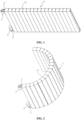
- FIG. 1 is a diagram illustrating the structure of a flexible screen support device in a flattened state according to an embodiment of the present application.
- FIG. 2 is a diagram illustrating the structure of a flexible screen support device in a bent state according to an embodiment of the present application.
- this embodiment of the present application provides a flexible screen support device applied to a bendable flexible screen product.
- the bendable flexible screen product includes, but not limited to, a smartphone, a smart wristwatch, and a smart tablet.
- the flexible screen support device includes a bending plate 1, a connection rope 2, and a driving mechanism 3.
- the bending plate 1 has a surface configured to support a flexible screen and may be bent to have a bent state and a flattened state such that the flexible screen is bent and flattened correspondingly.
- the bending plate 1 includes multiple support blocks 11 hingedly connected in sequence. Surfaces of at least one side of the multiple support blocks 11 together constitute a surface configured to support the flexible screen.
- the width of the upper part of each support block 11 gradually decreases, that is, the width of the upper part of a support block 11 is smaller than the width of the lower part of the support block 11.
- the bending plate 1 is bent and deformed through a mutual cooperation of the multiple support blocks 11 hingedly connected in sequence, thereby implementing the conversion of the flexible screen support device between the bent state and the flattened state.
- the "upper part” refers to the upper portion of a support block 11 in FIG. 1
- the “lower part” refers to the lower portion of a support block 11 in FIG. 1 .
- connection rope 2 may be a thin rope of a soft elastic material.
- One part of the connection rope 2 penetrates through the upper parts of the multiple support blocks 11 in sequence.
- the other part of the connection rope 2 penetrates through the lower parts of the multiple support blocks 11 in sequence.
- connection rope 2 is connected to the driving mechanism 3.
- the driving mechanism 3 is connected to a control apparatus in a signal manner, and by cooperating with the software control system of an intelligent terminal, the bending or flattening of the flexible screen can be implemented by one-key operation.
- the bending angle of the flexible screen support device may be set in advance and may be set according to the material performance of the flexible screen, the use scenario of a user, or the like, to ensure that the flexible screen can be maintained at a proper bend radius during bending, without being damaged due to a too small bend radius or an excessive force.
- the flexible screen support device can provide reliable hard support for the flexible screen when the flexible screen is flattened.
- the preceding preset bending angle is not limited to one, and multiple bending angles may also be set to meet the requirements of safe use.
- a user can implement the conversion of the flexible screen between different bent states through a software control system.
- a flexible screen support device capable of automatically bending.
- the connection rope 2 is driven by the driving mechanism 3.
- the upper part of the bending plate 1 is tightened by the connection rope 2
- upper parts of two adjacent support blocks 11 in the bending plate 1 are in contact with each other, and the bending plate 1 is in the bent state.
- the lower part of the bending plate 1 is tightened by the connection rope 2
- the upper parts of two adjacent support blocks 11 in the bending plate 1 have a rotation gap, and the bending plate 1 is in the flattened state.
- the present application implements the automatic bending and automatic flattening of the flexible screen, ensures the use safety of the flexible screen, enhances the convenience and intelligence of the product, makes the product more scientific and technical, and helps to improve the user experience.
- the driving mechanism 3 may be a motor
- the connection rope 2 is a whole rope.
- One end of the connection rope 2 is secured to the upper part of the support block 11 at an end (that is, the end facing away from the driving mechanism 3).
- the other end of the connection rope 2 is secured to the lower part of the support block 11 at the end.
- the middle portion of the connection rope 2 is secured to the output shaft of the motor.
- one end of the connection rope 2 may be tightened, and the other end of the connection rope 2 may be loosed.
- at least two groups of connection ropes 2 and at least two groups of motors may be provided.
- the at least two groups of connection ropes 2 are uniformly distributed along the length direction of the support blocks 11.
- connection ropes 2 are connected to the at least two groups of motors in a one-to-one manner. This arrangement can improve the movement balance of the bending plate 1 to form a better support for the flexible screen. In other embodiments, only one group of motors may be provided. Through the cooperation between the one group of motors and a transmission system, multiple groups of connection ropes 2 can be driven to move, thereby simplifying the structure and saving the cost.
- FIG. 3 is a diagram illustrating an exploded structure of a support block 11 and a connection rod 12 according to an embodiment of the present application.
- FIG. 4 is a cross-sectional diagram of a support block 11 according to an embodiment of the present application.
- the support block 11 may have a columnar structure.
- the shapes and sizes of multiple support blocks 11 are the same.
- the upper cross section of the support block 11 is in a shape of a trapezoid.
- the lower cross section of the support block 11 is in a shape of a rectangle.
- the base length of the trapezoid is the same as the top length of the rectangle, that is, the entire cross section of the support block 11 is in a shape of a hexagon.
- the lower end surface of the support block 11 may be provided to abut the flexible screen.
- the preceding trapezoidal structure not only makes the width of the upper part of the support block 11 smaller than the width of the lower part of the support block 11, but also increases the contact area between the lower end surface of the support block 11 and the flexible screen, thereby improving the support effect of the support block 11 on the flexible screen.
- the upper cross section of the support block 11 may be in a shape of an isosceles trapezoid. Thus, two sides of the support block 11 are subjected to relatively uniform forces, the folding performance of the bending plate 1 is better improved, and the folding performance of the intelligent terminal is further improved.
- the bending degree of the bending plate 1 is related to the shape, size, and number of the support blocks 11 and the size of the rotation gap.
- the foldable degree of the support block 11 may be adjusted through adjusting the base angle of the preceding isosceles trapezoid. The larger the base angle of the isosceles trapezoid is, the smaller the foldable degree of the single support block 11 is, and in the entire bending plate 1, the more support blocks 11 are required to achieve the same bending degree.
- the shape and the number of support blocks 11 can be set according to actual requirements and are not limited to this embodiment.
- the bending plate 1 also includes connection rods 12.
- the side wall of the support block 11 is provided with a mounting hole 111.
- a connection rod 12 is inserted through mounting holes 111 of two adjacent support blocks 11.
- two adjacent support blocks 11 are connected hingedly by using the connection rod 12 as a rotating shaft, and the structure is simple and the installation is convenient.
- the hinged connection among the support blocks 11 may be implemented in other manners and is not limited to this embodiment.
- the support blocks 11 and the connection rod 12 are each made of a hard material, such as a metal or a hard plastic, to increase the overall support performance and bending reliability of the bending plate 1.
- FIG. 5 is a diagram illustrating a bending process of a flexible screen support device according to an embodiment of the present application.
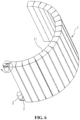
- FIG. 6 is a diagram illustrating a flattening process of a flexible screen support device according to an embodiment of the present application. Referring to FIG. 5 and FIG. 6 , the working principle of this embodiment is described below.
- a software system controls the output shaft of the motor to rotate counterclockwise along the direction shown by the arrow in FIG. 5 , thereby driving the connection rope 2 to rotate counterclockwise along with the output shaft of the motor.
- the connection rope 2 pulls the upper half of the bending plate 1 to be tightened and the lower half of the bending plate 1 to be loosened. Since the upper halves of the support block 11 is a trapezoidal structure, the upper half of multiple support blocks 11 are pressed against one another one by one so that the entire bending plate 1 is automatically bent.
- a final state is shown in FIG. 2 .
- the software system controls the output shaft of the motor to rotate clockwise along the direction shown by the arrow in FIG. 6 , thereby driving the connection rope 2 to rotate clockwise along with the output shaft of the motor.
- the connection rope 2 pulls the lower half of the bending plate 1 to be tightened and the upper half of the bending plate 1 to be loosened. Since the lower half of the support block 11 is a trapezoidal structure, the lower halves of multiple support blocks 11 are pressed against one another one by one so that the entire bending plate 1 is automatically flattened.
- a final state is shown in FIG. 1 .
- An embodiment of the present application provides an intelligent terminal.
- the intelligent terminal includes a flexible screen and the preceding flexible screen support device.
- the flexible screen is disposed on the flexible screen support device.
- the flexible screen is adhesively attached to the lower end surfaces of the multiple support blocks 11.
- the intelligent terminal may be a smartphone, a smartwatch, a smart tablet, or the like.
- the intelligent terminal when the intelligent terminal is a smart wristwatch, the smart wristwatch may be bent and folded into a shape of a band by the control of a software interface to facilitate a user to wear the wristwatch on the wrist.
- This embodiment implements the automatic bending and flattening of the intelligent terminal, avoids damage to the flexible screen of the intelligent terminal caused by manual operation, improves the convenience and intelligence of the product, and helps to improve the user experience.
Landscapes
- Engineering & Computer Science (AREA)
- General Engineering & Computer Science (AREA)
- Theoretical Computer Science (AREA)
- Computer Hardware Design (AREA)
- Physics & Mathematics (AREA)
- General Physics & Mathematics (AREA)
- Mechanical Engineering (AREA)
- Human Computer Interaction (AREA)
- Devices For Indicating Variable Information By Combining Individual Elements (AREA)
- Overhead Projectors And Projection Screens (AREA)
Abstract
Description
- The present application relates to the technical field of communications, for example, a flexible screen support device and an intelligent terminal.
- A large-screen terminal can bring a user better audio-visual enjoyment of surfing the Internet and playing games, but the large-screen terminal is not convenient to carry. A small-screen terminal is convenient to carry, but the experience of surfing the Internet, playing games, and watching videos is not good enough. Therefore, there is a need for a terminal that can change the size of a display screen area according to the needs of the user and combines the dual advantages of the sensory enjoyment of a large screen and the portability of a small screen.
- To meet the preceding requirements, an intelligent terminal with a deformable flexible screen emerges. A flexible screen can be bent freely to enable a display-type smart terminal product to get rid of an inherent rigid structure. Thus, a flexible screen terminal can change the size of the actual display screen area according to the needs of the user, thereby combining the sensory enjoyment of the large screen and the portability of the small screen. This has become an important development direction of smart terminal products.
- Both a flexible screen terminal and a foldable screen terminal are manually operated to bend the flexible screen. During a bending process, the flexible screen may be damaged due to the excessive manual operation force of the user. At the same time, since the manual operation lacks convenience and the sense of science and technology, the user experience is poor.
- The present application provides a flexible screen support device and an intelligent terminal to avoid damage to a flexible screen during a bending process and improve the convenience and intelligence of products.
- A flexible screen support device includes a bending plate, a connection rope, and a driving mechanism. The bending plate includes multiple support blocks hingedly connected in sequence. The width of the upper part of each support block gradually decreases to form a rotation gap between adjacent support blocks. One part of the connection rope penetrates through upper parts of the multiple support blocks. The other part of the connection rope penetrates through lower parts of the multiple support blocks. The driving mechanism is connected to the connection rope. The driving mechanism is configured to pull the one part of the connection rope so that the upper parts of adjacent support blocks are in contact with one another to bend the bending plate. The driving mechanism is also configured to pull the other part of the connection rope so that the upper parts of the adjacent support blocks are separated from one another to flatten the bending plate.
- An intelligent terminal includes a flexible screen and the preceding flexible screen support device. The flexible screen is disposed on the flexible screen support device.
-
-
FIG. 1 is a diagram illustrating a structure of a flexible screen support device in a flattened state according to an embodiment of the present application. -
FIG. 2 is a diagram illustrating a structure of a flexible screen support device in a bent state according to an embodiment of the present application. -
FIG. 3 is a diagram illustrating an exploded structure of a support block and a connection rod according to an embodiment of the present application. -
FIG. 4 is a cross-sectional diagram of a support block according to an embodiment of the present application. -
FIG. 5 is a diagram illustrating a bending process of a flexible screen support device according to an embodiment of the present application. -
FIG. 6 is a diagram illustrating a flattening process of a flexible screen support device according to an embodiment of the present application. -
- 1
- bending plate
- 11
- support block
- 111
- mounting hole
- 12
- connection rod
- 2
- connection rope
- 3
- driving mechanism
- The present application is described hereinafter in conjunction with drawings and embodiments.
- In the description of the present application, unless otherwise specified and limited, the term "connected to each other", "connected", or "secured" is to be construed in a broad sense, for example, as securely connected, detachably connected, or integrated; mechanically connected or electrically connected; directly connected to each other or indirectly connected to each other via an intermediary; or internally connected or interactional between two components. The meanings of the preceding terms in the present application may be understood according to situations.
- In the present application, unless otherwise specified and limited, when a first feature is described as "above" or "below" a second feature, the first feature and the second feature may be in direct contact, or be in contact via another feature between the two features. Moreover, when the first feature is described as "on", "above", or "over" the second feature, the first feature is right on, above, or over the second feature or the first feature is obliquely on, above, or over the second feature, or the first feature is simply at a higher level than the second feature. When the first feature is described as "under", "below", or "underneath" the second feature, the first feature is right under, below, or underneath the second feature or the first feature is obliquely under, below, or underneath the second feature, or the first feature is simply at a lower level than the second feature.
- In the description of the present application, it is to be understood that the orientation or position relationships indicated by terms "above", "below", "left" "right" and the like are based on the orientation or position relationships shown in the drawings, merely for facilitating description of the present application and simplifying operation, and these relationships do not indicate or imply that the referred device or element has a specific orientation and is constructed and operated in a specific orientation, and thus it is not to be construed as limiting the present application. Additionally, the terms "first" and "second" in the specification are only used for descriptive purposes and have no special meanings.
-
FIG. 1 is a diagram illustrating the structure of a flexible screen support device in a flattened state according to an embodiment of the present application.FIG. 2 is a diagram illustrating the structure of a flexible screen support device in a bent state according to an embodiment of the present application. Referring toFIG. 1 and FIG. 2 , this embodiment of the present application provides a flexible screen support device applied to a bendable flexible screen product. The bendable flexible screen product includes, but not limited to, a smartphone, a smart wristwatch, and a smart tablet. The flexible screen support device includes abending plate 1, aconnection rope 2, and adriving mechanism 3. Thebending plate 1 has a surface configured to support a flexible screen and may be bent to have a bent state and a flattened state such that the flexible screen is bent and flattened correspondingly. Thebending plate 1 includesmultiple support blocks 11 hingedly connected in sequence. Surfaces of at least one side of themultiple support blocks 11 together constitute a surface configured to support the flexible screen. The width of the upper part of eachsupport block 11 gradually decreases, that is, the width of the upper part of asupport block 11 is smaller than the width of the lower part of thesupport block 11. When thebending plate 1 is in the flattened state, upper parts of two adjacent support blocks 11 form a rotation gap. When thebending plate 1 is in the bent state, the upper parts of twoadjacent support blocks 11 are in contact with each other. The bendingplate 1 is bent and deformed through a mutual cooperation of themultiple support blocks 11 hingedly connected in sequence, thereby implementing the conversion of the flexible screen support device between the bent state and the flattened state. In this embodiment of the present application, the "upper part" refers to the upper portion of asupport block 11 inFIG. 1 , and the "lower part" refers to the lower portion of asupport block 11 inFIG. 1 . These terms are merely for facilitating description and do not indicate or imply that thesupport block 11 must have a specific orientation. - In this embodiment of the present application, the
connection rope 2 may be a thin rope of a soft elastic material. One part of theconnection rope 2 penetrates through the upper parts of the multiple support blocks 11 in sequence. The other part of theconnection rope 2 penetrates through the lower parts of the multiple support blocks 11 in sequence. When the bendingplate 1 is in the flattened state, the upper parts of the multiple support blocks 11 are tightened and the lower parts of the multiple support blocks 11 are loosened by theconnection rope 2. Thus, the upper parts of the multiple support blocks 11 in thebending plate 1 can be attached in sequence, the lower parts of the multiple support blocks 11 appear gaps, and thebending plate 1 is bent towards the direction of the upper parts. When the bendingplate 1 is in the bent state, the lower parts of the multiple support blocks 11 are tightened and the upper parts of the multiple support blocks 11 are loosened by theconnection rope 2. Thus, the lower parts of two adjacent support blocks 11 in thebending plate 1 can be attached in sequence, the upper parts of two adjacent support blocks 11 appear gaps, and thebending plate 1 is flattened towards the direction of the lower parts. In this embodiment, theconnection rope 2 is connected to thedriving mechanism 3. Thus, theconnection rope 2 can be tightened or loosened under the driving of thedriving mechanism 3. Thedriving mechanism 3 is connected to a control apparatus in a signal manner, and by cooperating with the software control system of an intelligent terminal, the bending or flattening of the flexible screen can be implemented by one-key operation. - In this embodiment of the present application, the bending angle of the flexible screen support device may be set in advance and may be set according to the material performance of the flexible screen, the use scenario of a user, or the like, to ensure that the flexible screen can be maintained at a proper bend radius during bending, without being damaged due to a too small bend radius or an excessive force. Moreover, the flexible screen support device can provide reliable hard support for the flexible screen when the flexible screen is flattened. The preceding preset bending angle is not limited to one, and multiple bending angles may also be set to meet the requirements of safe use. A user can implement the conversion of the flexible screen between different bent states through a software control system.
- In this embodiment of the present application, a flexible screen support device capable of automatically bending is provided. The
connection rope 2 is driven by thedriving mechanism 3. When the upper part of thebending plate 1 is tightened by theconnection rope 2, upper parts of two adjacent support blocks 11 in thebending plate 1 are in contact with each other, and thebending plate 1 is in the bent state. When the lower part of thebending plate 1 is tightened by theconnection rope 2, the upper parts of two adjacent support blocks 11 in thebending plate 1 have a rotation gap, and thebending plate 1 is in the flattened state. Thus, automatic bending and automatic flattening of the flexible screen are implemented. The present application implements the automatic bending and automatic flattening of the flexible screen, ensures the use safety of the flexible screen, enhances the convenience and intelligence of the product, makes the product more scientific and technical, and helps to improve the user experience. - In this embodiment, the
driving mechanism 3 may be a motor, and theconnection rope 2 is a whole rope. One end of theconnection rope 2 is secured to the upper part of thesupport block 11 at an end (that is, the end facing away from the driving mechanism 3). The other end of theconnection rope 2 is secured to the lower part of thesupport block 11 at the end. The middle portion of theconnection rope 2 is secured to the output shaft of the motor. Thus, when the motor is rotated, one end of theconnection rope 2 may be tightened, and the other end of theconnection rope 2 may be loosed. In this embodiment, at least two groups ofconnection ropes 2 and at least two groups of motors may be provided. The at least two groups ofconnection ropes 2 are uniformly distributed along the length direction of the support blocks 11. The at least two groups ofconnection ropes 2 are connected to the at least two groups of motors in a one-to-one manner. This arrangement can improve the movement balance of thebending plate 1 to form a better support for the flexible screen. In other embodiments, only one group of motors may be provided. Through the cooperation between the one group of motors and a transmission system, multiple groups ofconnection ropes 2 can be driven to move, thereby simplifying the structure and saving the cost. -
FIG. 3 is a diagram illustrating an exploded structure of asupport block 11 and aconnection rod 12 according to an embodiment of the present application.FIG. 4 is a cross-sectional diagram of asupport block 11 according to an embodiment of the present application. Referring toFIG. 3 andFIG. 4 , in this embodiment, thesupport block 11 may have a columnar structure. The shapes and sizes of multiple support blocks 11 are the same. The upper cross section of thesupport block 11 is in a shape of a trapezoid. The lower cross section of thesupport block 11 is in a shape of a rectangle. The base length of the trapezoid is the same as the top length of the rectangle, that is, the entire cross section of thesupport block 11 is in a shape of a hexagon. In this embodiment, the lower end surface of thesupport block 11 may be provided to abut the flexible screen. The preceding trapezoidal structure not only makes the width of the upper part of thesupport block 11 smaller than the width of the lower part of thesupport block 11, but also increases the contact area between the lower end surface of thesupport block 11 and the flexible screen, thereby improving the support effect of thesupport block 11 on the flexible screen. In an embodiment, the upper cross section of thesupport block 11 may be in a shape of an isosceles trapezoid. Thus, two sides of thesupport block 11 are subjected to relatively uniform forces, the folding performance of thebending plate 1 is better improved, and the folding performance of the intelligent terminal is further improved. In this embodiment, the bending degree of thebending plate 1 is related to the shape, size, and number of the support blocks 11 and the size of the rotation gap. For example, the foldable degree of thesupport block 11 may be adjusted through adjusting the base angle of the preceding isosceles trapezoid. The larger the base angle of the isosceles trapezoid is, the smaller the foldable degree of thesingle support block 11 is, and in theentire bending plate 1, the more support blocks 11 are required to achieve the same bending degree. In application, the shape and the number of support blocks 11 can be set according to actual requirements and are not limited to this embodiment. - With continued reference to
FIG. 3 , in this embodiment, the bendingplate 1 also includesconnection rods 12. The side wall of thesupport block 11 is provided with a mountinghole 111. Aconnection rod 12 is inserted through mountingholes 111 of two adjacent support blocks 11. In this embodiment, two adjacent support blocks 11 are connected hingedly by using theconnection rod 12 as a rotating shaft, and the structure is simple and the installation is convenient. In other embodiments, the hinged connection among the support blocks 11 may be implemented in other manners and is not limited to this embodiment. In this embodiment, the support blocks 11 and theconnection rod 12 are each made of a hard material, such as a metal or a hard plastic, to increase the overall support performance and bending reliability of thebending plate 1. -
FIG. 5 is a diagram illustrating a bending process of a flexible screen support device according to an embodiment of the present application.FIG. 6 is a diagram illustrating a flattening process of a flexible screen support device according to an embodiment of the present application. Referring toFIG. 5 andFIG. 6 , the working principle of this embodiment is described below. - As shown in
FIG. 5 , when the whole machine is in the flattened state and needs to be bent, a software system controls the output shaft of the motor to rotate counterclockwise along the direction shown by the arrow inFIG. 5 , thereby driving theconnection rope 2 to rotate counterclockwise along with the output shaft of the motor. Theconnection rope 2 pulls the upper half of thebending plate 1 to be tightened and the lower half of thebending plate 1 to be loosened. Since the upper halves of thesupport block 11 is a trapezoidal structure, the upper half of multiple support blocks 11 are pressed against one another one by one so that theentire bending plate 1 is automatically bent. A final state is shown inFIG. 2 . - As shown in
FIG. 6 , when the whole machine is in the bent state and needs to be flattened, the software system controls the output shaft of the motor to rotate clockwise along the direction shown by the arrow inFIG. 6 , thereby driving theconnection rope 2 to rotate clockwise along with the output shaft of the motor. Theconnection rope 2 pulls the lower half of thebending plate 1 to be tightened and the upper half of thebending plate 1 to be loosened. Since the lower half of thesupport block 11 is a trapezoidal structure, the lower halves of multiple support blocks 11 are pressed against one another one by one so that theentire bending plate 1 is automatically flattened. A final state is shown inFIG. 1 . - An embodiment of the present application provides an intelligent terminal. The intelligent terminal includes a flexible screen and the preceding flexible screen support device. The flexible screen is disposed on the flexible screen support device. In an embodiment, the flexible screen is adhesively attached to the lower end surfaces of the multiple support blocks 11. In this embodiment, the intelligent terminal may be a smartphone, a smartwatch, a smart tablet, or the like. For example, when the intelligent terminal is a smart wristwatch, the smart wristwatch may be bent and folded into a shape of a band by the control of a software interface to facilitate a user to wear the wristwatch on the wrist. This embodiment implements the automatic bending and flattening of the intelligent terminal, avoids damage to the flexible screen of the intelligent terminal caused by manual operation, improves the convenience and intelligence of the product, and helps to improve the user experience.
Claims (10)
- A flexible screen support device, comprising:a bending plate (1), wherein the bending plate (1) comprises a plurality of support blocks (11) hingedly connected in sequence, and a width of an upper part of each of the plurality of support blocks (11) gradually decreases to form a rotation gap between adjacent support blocks (11) of the plurality of support blocks (11);a connection rope (2), wherein one part of the connection rope (2) penetrates through upper parts of the plurality of support blocks (11), and another part of the connection rope (2) penetrates through lower parts of the plurality of support blocks (11); anda driving mechanism (3) connected to the connection rope (2), wherein the driving mechanism (3) is configured to pull the one part of the connection rope (2) so that upper parts of adjacent support blocks (11) of the plurality of support blocks (11) are in contact with one another to bend the bending plate (1), and the driving mechanism (3) is further configured to pull the another part of the connection rope (2) so that the upper parts of the adjacent support blocks (11) of the plurality of support blocks (11) are separated from one another to flatten the bending plate (1).
- The flexible screen support device according to claim 1, wherein the each of the plurality of support blocks (11) has a columnar structure, an upper cross section of the each of the plurality of support blocks (11) is in a shape of a trapezoid, and a lower cross section of the each of the plurality of support blocks (11) is in a shape of a rectangle.
- The flexible screen support device according to claim 1, wherein the plurality of support blocks (11) have a same shape and a same size.
- The flexible screen support device according to claim 1, wherein the bending plate (1) further comprises a connection rod (12), a side wall of the each of the plurality of support blocks (11) is provided with a mounting hole (111), and the connection rod (12) is inserted through mounting holes (111) of two adjacent support blocks (11) of the plurality of support blocks (11) so that the two adjacent support blocks (11) are connected hingedly.
- The flexible screen support device according to claim 4, wherein the plurality of support blocks (11) and the connection rod (12) are each made of a hard material.
- The flexible screen support device according to any one of claims 1 to 5, wherein the driving mechanism (3) is a motor, one end of the connection rope (2) is secured to an upper part of a support block (11) of the plurality of support blocks (11) at an end, another end of the connection rope (2) is secured to a lower part of the support block (11) at the end, and a middle part of the connection rope (2) is secured to an output shaft of the motor, wherein the end is an end facing away from the driving mechanism (3).
- The flexible screen support device according to claim 6, wherein at least two groups of connection ropes (2) and at least two groups of driving mechanisms (3) are provided, the at least two groups of connection ropes (2) are uniformly distributed along a length direction of the plurality of support blocks (11), and each group of the at least two groups of connection ropes (2) is correspondingly connected to one group of the at least two groups of driving mechanisms (3).
- The flexible screen support device according to claim 1, wherein the connection rope (2) is a rope of a soft elastic material.
- An intelligent terminal, comprising a flexible screen and the flexible screen support device according to any one of claims 1 to 8, wherein the flexible screen is disposed on the flexible screen support device.
- The intelligent terminal according to claim 9, wherein the flexible screen abuts lower end surfaces of the plurality of support blocks (11) in the bending plate (1) of the flexible screen support device.
Applications Claiming Priority (2)
| Application Number | Priority Date | Filing Date | Title |
|---|---|---|---|
| CN202010538106.2A CN113803575B (en) | 2020-06-12 | 2020-06-12 | Flexible screen supporting device and intelligent terminal |
| PCT/CN2021/096265 WO2021249195A1 (en) | 2020-06-12 | 2021-05-27 | Flexible screen support device and intelligent terminal |
Publications (3)
| Publication Number | Publication Date |
|---|---|
| EP4130539A1 true EP4130539A1 (en) | 2023-02-08 |
| EP4130539A4 EP4130539A4 (en) | 2024-04-17 |
| EP4130539B1 EP4130539B1 (en) | 2026-03-04 |
Family
ID=78845245
Family Applications (1)
| Application Number | Title | Priority Date | Filing Date |
|---|---|---|---|
| EP21822518.3A Active EP4130539B1 (en) | 2020-06-12 | 2021-05-27 | Flexible screen support device and intelligent terminal |
Country Status (5)
| Country | Link |
|---|---|
| US (1) | US12197252B2 (en) |
| EP (1) | EP4130539B1 (en) |
| JP (1) | JP7432014B2 (en) |
| CN (1) | CN113803575B (en) |
| WO (1) | WO2021249195A1 (en) |
Families Citing this family (12)
| Publication number | Priority date | Publication date | Assignee | Title |
|---|---|---|---|---|
| CN116052539B (en) * | 2023-01-12 | 2025-05-27 | 京东方科技集团股份有限公司 | Flexible display module and display device |
| CN117128234B (en) * | 2023-03-13 | 2024-08-23 | 荣耀终端有限公司 | A supporting device and a folding screen terminal |
| CN116887553B (en) * | 2023-09-07 | 2023-12-19 | 深圳市格林兴显示科技有限公司 | Foldable display |
| CN117307891B (en) * | 2023-09-21 | 2025-09-30 | 泰州市创新电子有限公司 | A flexible screen support frame |
| USD1108421S1 (en) * | 2023-10-23 | 2026-01-06 | Motorola Mobility Llc | Display |
| USD1101046S1 (en) * | 2023-10-23 | 2025-11-04 | Motorola Mobility Llc | Display |
| USD1108387S1 (en) * | 2023-10-23 | 2026-01-06 | Motorola Mobility Llc | Display |
| USD1108422S1 (en) * | 2023-10-23 | 2026-01-06 | Motorola Mobility Llc | Display |
| USD1100872S1 (en) * | 2023-10-23 | 2025-11-04 | Motorola Mobility Llc | Display |
| USD1107700S1 (en) * | 2023-10-23 | 2025-12-30 | Motorola Mobility Llc | Display |
| USD1108386S1 (en) * | 2023-10-23 | 2026-01-06 | Motorola Mobility Llc | Display |
| USD1108425S1 (en) * | 2023-10-23 | 2026-01-06 | Motorola Mobility Llc | Display |
Family Cites Families (38)
| Publication number | Priority date | Publication date | Assignee | Title |
|---|---|---|---|---|
| GB0004688D0 (en) * | 2000-02-28 | 2000-04-19 | Radley Smith Philip J | Bracelet |
| JP2005316297A (en) | 2004-04-30 | 2005-11-10 | Sony Corp | Large screen |
| JP2007079271A (en) | 2005-09-15 | 2007-03-29 | Victor Co Of Japan Ltd | Display screen device |
| JP5229409B2 (en) | 2012-04-03 | 2013-07-03 | セイコーエプソン株式会社 | screen |
| US9120290B2 (en) * | 2012-10-10 | 2015-09-01 | Universal Display Corporation | Flexible screen backed with rigid ribs |
| CN203162459U (en) * | 2012-12-31 | 2013-08-28 | 东莞市票友机电科技有限公司 | An adjustable support frame |
| US20140337621A1 (en) * | 2013-05-07 | 2014-11-13 | Serguei Nakhimov | Wearable communication device, security complex and user interface |
| KR102189784B1 (en) * | 2013-08-30 | 2020-12-11 | 삼성전자주식회사 | Flexible electronic device |
| KR101547640B1 (en) * | 2013-09-16 | 2015-08-27 | (주) 프렉코 | Foldable flexible display device with guide device |
| KR102014445B1 (en) * | 2013-09-27 | 2019-08-29 | 삼성전자주식회사 | Wearable device |
| KR20230175342A (en) * | 2014-05-06 | 2023-12-29 | 가부시키가이샤 한도오따이 에네루기 켄큐쇼 | Electronic device |
| KR102015398B1 (en) * | 2014-07-16 | 2019-08-29 | 엘지디스플레이 주식회사 | Foldable display apparatus |
| GB201421202D0 (en) | 2014-11-28 | 2015-01-14 | Plastic Logic Ltd | Mobile device |
| CN204516278U (en) | 2014-12-30 | 2015-07-29 | 上海协度电子科技有限公司 | Flexible displays |
| CN104714699A (en) * | 2015-04-13 | 2015-06-17 | 京东方科技集团股份有限公司 | Flexible display device |
| KR102381657B1 (en) * | 2015-05-27 | 2022-04-04 | 삼성디스플레이 주식회사 | Hinge module apparatus |
| WO2017006419A1 (en) * | 2015-07-06 | 2017-01-12 | 堺ディスプレイプロダクト株式会社 | Display device |
| KR102366516B1 (en) * | 2015-08-31 | 2022-02-22 | 엘지디스플레이 주식회사 | Foldable display apparatus |
| CN205847346U (en) | 2016-06-07 | 2016-12-28 | 杭州安费诺飞凤通信部品有限公司 | The hinge of a kind of flexible screen mobile terminal, hinge means and flexible screen mobile terminal |
| KR102520575B1 (en) * | 2016-07-13 | 2023-04-11 | 삼성디스플레이 주식회사 | Display device |
| EP3489819A4 (en) | 2016-07-19 | 2020-03-18 | Shenzhen Royole Technologies Co., Ltd | Flexible device |
| EP3488726A4 (en) * | 2016-07-19 | 2019-07-31 | Shenzhen Royole Technologies Co., Ltd. | Flexible device |
| KR102479081B1 (en) * | 2016-07-28 | 2022-12-20 | 삼성전자주식회사 | Flexible housing and electronic device including the same |
| WO2016203321A2 (en) * | 2016-10-18 | 2016-12-22 | Almuhairbi, Eida | Motorized foldable flexible display |
| KR102562718B1 (en) | 2016-11-03 | 2023-08-02 | 삼성디스플레이 주식회사 | Display device |
| CN109257460B (en) * | 2017-07-12 | 2024-11-29 | 杭州安费诺飞凤通信部品有限公司 | Hinge of flexible screen mobile terminal and flexible screen mobile terminal |
| CN110770814B (en) * | 2017-08-03 | 2021-11-16 | 深圳市柔宇科技股份有限公司 | Folding mechanism and terminal |
| US11079807B1 (en) * | 2017-08-03 | 2021-08-03 | Apple Inc. | Friction roller hinge for electronic devices and method for making roller and spacer elements |
| KR102269604B1 (en) * | 2018-02-23 | 2021-06-28 | 삼성전자주식회사 | Electronic device including movable flexible display |
| CN112313729A (en) | 2018-03-12 | 2021-02-02 | 深圳市柔宇科技股份有限公司 | Bending components and flexible display devices |
| GB2573019B (en) | 2018-04-20 | 2022-11-02 | Korn Wall Ltd | A split tube extendable member system |
| CN108712529B (en) * | 2018-05-24 | 2020-10-23 | 维沃移动通信有限公司 | A hinge and mobile terminal |
| CN109164911B (en) * | 2018-07-12 | 2021-10-15 | 努比亚技术有限公司 | Wearable device and wearable device control method |
| CN208819536U (en) * | 2018-09-29 | 2019-05-03 | 中兴通讯股份有限公司 | A kind of flexible screen support construction and terminal |
| CN109574600B (en) | 2019-02-03 | 2021-09-24 | 黑龙江工业学院 | A kind of highly conductive graphite concrete |
| KR102668484B1 (en) * | 2019-07-29 | 2024-05-24 | 삼성디스플레이 주식회사 | Display device |
| CN110661908B (en) * | 2019-09-29 | 2021-03-12 | Oppo(重庆)智能科技有限公司 | Electronic device and control method of electronic device |
| EP4220342A4 (en) * | 2021-03-24 | 2024-05-29 | Samsung Electronics Co., Ltd. | ELECTRONIC DEVICE COMPRISING A FLEXIBLE DISPLAY |
-
2020
- 2020-06-12 CN CN202010538106.2A patent/CN113803575B/en active Active
-
2021
- 2021-05-27 WO PCT/CN2021/096265 patent/WO2021249195A1/en not_active Ceased
- 2021-05-27 JP JP2022574830A patent/JP7432014B2/en active Active
- 2021-05-27 EP EP21822518.3A patent/EP4130539B1/en active Active
- 2021-05-27 US US17/923,400 patent/US12197252B2/en active Active
Also Published As
| Publication number | Publication date |
|---|---|
| CN113803575B (en) | 2025-09-16 |
| EP4130539A4 (en) | 2024-04-17 |
| JP2023529659A (en) | 2023-07-11 |
| WO2021249195A1 (en) | 2021-12-16 |
| EP4130539B1 (en) | 2026-03-04 |
| JP7432014B2 (en) | 2024-02-15 |
| US12197252B2 (en) | 2025-01-14 |
| US20230194043A1 (en) | 2023-06-22 |
| CN113803575A (en) | 2021-12-17 |
Similar Documents
| Publication | Publication Date | Title |
|---|---|---|
| EP4130539B1 (en) | Flexible screen support device and intelligent terminal | |
| US11032405B2 (en) | Flexible screen mobile terminal | |
| AU2016307504B2 (en) | A flexible display screen and TV set thereof | |
| US11098788B2 (en) | Curvature-adjustable backboard assembly and curved display device | |
| CN111047995B (en) | Flexible display device | |
| US10018331B2 (en) | Back plate assembly with variable curvatures and backlight unit thereof | |
| CN107690304B (en) | flexible device | |
| WO2021223537A1 (en) | Supporting device for flexible screen and flexible screen terminal | |
| CN113284422B (en) | Electronic equipment | |
| US10480755B2 (en) | Back plate assembly with variable curvatures and backlight unit thereof | |
| CN209674772U (en) | A flexible display device | |
| US11620924B2 (en) | Retractable apparatus | |
| WO2019090942A1 (en) | Display device capable of curved deformation | |
| CN113329109A (en) | Electronic device | |
| CN107545849A (en) | Flexible display apparatus | |
| WO2020098391A1 (en) | Conference table | |
| WO2024016138A1 (en) | Support module, display module, and display device | |
| US11199875B2 (en) | Display device | |
| CN107331303B (en) | Curved-surface display device and its curvature regulating mechanism | |
| CN117128234B (en) | A supporting device and a folding screen terminal | |
| CN109687641A (en) | A kind of device of driving motor clutch | |
| CN113470517A (en) | Electronic device | |
| CN112489561B (en) | Foldable display device | |
| CN220798525U (en) | Mixed volume control device | |
| CN115737392B (en) | Head-mounted device and head massage equipment |
Legal Events
| Date | Code | Title | Description |
|---|---|---|---|
| STAA | Information on the status of an ep patent application or granted ep patent |
Free format text: STATUS: THE INTERNATIONAL PUBLICATION HAS BEEN MADE |
|
| PUAI | Public reference made under article 153(3) epc to a published international application that has entered the european phase |
Free format text: ORIGINAL CODE: 0009012 |
|
| STAA | Information on the status of an ep patent application or granted ep patent |
Free format text: STATUS: REQUEST FOR EXAMINATION WAS MADE |
|
| 17P | Request for examination filed |
Effective date: 20221103 |
|
| AK | Designated contracting states |
Kind code of ref document: A1 Designated state(s): AL AT BE BG CH CY CZ DE DK EE ES FI FR GB GR HR HU IE IS IT LI LT LU LV MC MK MT NL NO PL PT RO RS SE SI SK SM TR |
|
| DAV | Request for validation of the european patent (deleted) | ||
| DAX | Request for extension of the european patent (deleted) | ||
| REG | Reference to a national code |
Ref legal event code: R079 Free format text: PREVIOUS MAIN CLASS: F16M0011040000 Ref country code: DE Ref legal event code: R079 Ref document number: 602021049385 Country of ref document: DE Free format text: PREVIOUS MAIN CLASS: F16M0011040000 Ipc: F16M0011080000 |
|
| A4 | Supplementary search report drawn up and despatched |
Effective date: 20240315 |
|
| RIC1 | Information provided on ipc code assigned before grant |
Ipc: F16M 11/18 20060101ALI20240312BHEP Ipc: G09F 9/30 20060101ALI20240312BHEP Ipc: G06F 1/16 20060101ALI20240312BHEP Ipc: F16M 11/08 20060101AFI20240312BHEP |
|
| STAA | Information on the status of an ep patent application or granted ep patent |
Free format text: STATUS: EXAMINATION IS IN PROGRESS |
|
| 17Q | First examination report despatched |
Effective date: 20250205 |
|
| RAP1 | Party data changed (applicant data changed or rights of an application transferred) |
Owner name: DRNC HOLDINGS, INC. |
|
| GRAP | Despatch of communication of intention to grant a patent |
Free format text: ORIGINAL CODE: EPIDOSNIGR1 |
|
| STAA | Information on the status of an ep patent application or granted ep patent |
Free format text: STATUS: GRANT OF PATENT IS INTENDED |
|
| INTG | Intention to grant announced |
Effective date: 20251007 |
|
| GRAS | Grant fee paid |
Free format text: ORIGINAL CODE: EPIDOSNIGR3 |
|
| GRAA | (expected) grant |
Free format text: ORIGINAL CODE: 0009210 |
|
| STAA | Information on the status of an ep patent application or granted ep patent |
Free format text: STATUS: THE PATENT HAS BEEN GRANTED |
|
| AK | Designated contracting states |
Kind code of ref document: B1 Designated state(s): AL AT BE BG CH CY CZ DE DK EE ES FI FR GB GR HR HU IE IS IT LI LT LU LV MC MK MT NL NO PL PT RO RS SE SI SK SM TR |
|
| P01 | Opt-out of the competence of the unified patent court (upc) registered |
Free format text: CASE NUMBER: UPC_APP_0002773_4130539/2026 Effective date: 20260126 |
|
| REG | Reference to a national code |
Ref country code: CH Ref legal event code: F10 Free format text: ST27 STATUS EVENT CODE: U-0-0-F10-F00 (AS PROVIDED BY THE NATIONAL OFFICE) Effective date: 20260304 Ref country code: GB Ref legal event code: FG4D |
|
| REG | Reference to a national code |
Ref country code: IE Ref legal event code: FG4D |
|
| REG | Reference to a national code |
Ref country code: DE Ref legal event code: R096 Ref document number: 602021049385 Country of ref document: DE |