EP4130498A1 - Sliding member and method for driving sliding member - Google Patents
Sliding member and method for driving sliding member Download PDFInfo
- Publication number
- EP4130498A1 EP4130498A1 EP22184130.7A EP22184130A EP4130498A1 EP 4130498 A1 EP4130498 A1 EP 4130498A1 EP 22184130 A EP22184130 A EP 22184130A EP 4130498 A1 EP4130498 A1 EP 4130498A1
- Authority
- EP
- European Patent Office
- Prior art keywords
- peripheral face
- shaft member
- outer peripheral
- bearing member
- inner peripheral
- Prior art date
- Legal status (The legal status is an assumption and is not a legal conclusion. Google has not performed a legal analysis and makes no representation as to the accuracy of the status listed.)
- Granted
Links
Images





Classifications
-
- F—MECHANICAL ENGINEERING; LIGHTING; HEATING; WEAPONS; BLASTING
- F16—ENGINEERING ELEMENTS AND UNITS; GENERAL MEASURES FOR PRODUCING AND MAINTAINING EFFECTIVE FUNCTIONING OF MACHINES OR INSTALLATIONS; THERMAL INSULATION IN GENERAL
- F16C—SHAFTS; FLEXIBLE SHAFTS; ELEMENTS OR CRANKSHAFT MECHANISMS; ROTARY BODIES OTHER THAN GEARING ELEMENTS; BEARINGS
- F16C17/00—Sliding-contact bearings for exclusively rotary movement
- F16C17/02—Sliding-contact bearings for exclusively rotary movement for radial load only
-
- F—MECHANICAL ENGINEERING; LIGHTING; HEATING; WEAPONS; BLASTING
- F16—ENGINEERING ELEMENTS AND UNITS; GENERAL MEASURES FOR PRODUCING AND MAINTAINING EFFECTIVE FUNCTIONING OF MACHINES OR INSTALLATIONS; THERMAL INSULATION IN GENERAL
- F16C—SHAFTS; FLEXIBLE SHAFTS; ELEMENTS OR CRANKSHAFT MECHANISMS; ROTARY BODIES OTHER THAN GEARING ELEMENTS; BEARINGS
- F16C33/00—Parts of bearings; Special methods for making bearings or parts thereof
- F16C33/02—Parts of sliding-contact bearings
- F16C33/04—Brasses; Bushes; Linings
- F16C33/06—Sliding surface mainly made of metal
- F16C33/10—Construction relative to lubrication
-
- F—MECHANICAL ENGINEERING; LIGHTING; HEATING; WEAPONS; BLASTING
- F16—ENGINEERING ELEMENTS AND UNITS; GENERAL MEASURES FOR PRODUCING AND MAINTAINING EFFECTIVE FUNCTIONING OF MACHINES OR INSTALLATIONS; THERMAL INSULATION IN GENERAL
- F16C—SHAFTS; FLEXIBLE SHAFTS; ELEMENTS OR CRANKSHAFT MECHANISMS; ROTARY BODIES OTHER THAN GEARING ELEMENTS; BEARINGS
- F16C2202/00—Solid materials defined by their properties
- F16C2202/02—Mechanical properties
- F16C2202/04—Hardness
-
- F—MECHANICAL ENGINEERING; LIGHTING; HEATING; WEAPONS; BLASTING
- F16—ENGINEERING ELEMENTS AND UNITS; GENERAL MEASURES FOR PRODUCING AND MAINTAINING EFFECTIVE FUNCTIONING OF MACHINES OR INSTALLATIONS; THERMAL INSULATION IN GENERAL
- F16C—SHAFTS; FLEXIBLE SHAFTS; ELEMENTS OR CRANKSHAFT MECHANISMS; ROTARY BODIES OTHER THAN GEARING ELEMENTS; BEARINGS
- F16C2223/00—Surface treatments; Hardening; Coating
-
- F—MECHANICAL ENGINEERING; LIGHTING; HEATING; WEAPONS; BLASTING
- F16—ENGINEERING ELEMENTS AND UNITS; GENERAL MEASURES FOR PRODUCING AND MAINTAINING EFFECTIVE FUNCTIONING OF MACHINES OR INSTALLATIONS; THERMAL INSULATION IN GENERAL
- F16C—SHAFTS; FLEXIBLE SHAFTS; ELEMENTS OR CRANKSHAFT MECHANISMS; ROTARY BODIES OTHER THAN GEARING ELEMENTS; BEARINGS
- F16C2233/00—Monitoring condition, e.g. temperature, load, vibration
-
- Y—GENERAL TAGGING OF NEW TECHNOLOGICAL DEVELOPMENTS; GENERAL TAGGING OF CROSS-SECTIONAL TECHNOLOGIES SPANNING OVER SEVERAL SECTIONS OF THE IPC; TECHNICAL SUBJECTS COVERED BY FORMER USPC CROSS-REFERENCE ART COLLECTIONS [XRACs] AND DIGESTS
- Y02—TECHNOLOGIES OR APPLICATIONS FOR MITIGATION OR ADAPTATION AGAINST CLIMATE CHANGE
- Y02T—CLIMATE CHANGE MITIGATION TECHNOLOGIES RELATED TO TRANSPORTATION
- Y02T10/00—Road transport of goods or passengers
- Y02T10/80—Technologies aiming to reduce greenhouse gasses emissions common to all road transportation technologies
- Y02T10/86—Optimisation of rolling resistance, e.g. weight reduction
Definitions
- the present invention relates to a sliding member and a method for driving a sliding member.
- a sliding member for a ship includes: for example, a shaft member such as a crankshaft, an intermediate shaft, a propulsion shaft, or the like; and a bearing member such as a slide bearing or the like which slidably supports the shaft member. Furthermore, lubricating oil is supplied to a gap between the shaft member and the bearing member. The lubricating oil forms an oil film between the shaft member and the bearing member to inhibit frictional resistance between these members.
- a main factor of the frictional resistance is a viscosity of the oil film, and thus low frictional resistance tends to be maintained.
- the thickness of the oil film relative to the surface roughness of the sliding face is insufficient, not only the viscosity of the oil film but also a solid contact between the shaft member and the bearing member may become a factor of the frictional resistance, and thus the frictional resistance is likely to increase.
- seizure is likely to occur on the sliding face. Therefore, by forming a favorable oil film, a friction loss and seizure on the sliding face can be effectively inhibited.
- Patent Document 1 discloses a crank lubrication system for reducing a friction loss of a crankshaft.
- Patent Document 2 discloses a simple processing method of a rotary shaft having a lubricating oil-retaining function.
- the present invention was made in view of the foregoing circumstances, and an object of the present invention is to provide a sliding member which enables inhibition of a friction loss and seizure between a shaft member and a bearing member.
- a sliding member according to one aspect of the present invention made to solve the aforementioned problems includes: a shaft member having a shaft diameter D of greater than or equal to 0.18 m; a bearing member which slidably supports an outer peripheral face of the shaft member; and a lubricating oil which is supplied to a gap between the outer peripheral face of the shaft member and an inner peripheral face of the bearing member and forms an oil film in the gap, wherein an arithmetic mean roughness Ra 1 of the outer peripheral face of the shaft member is less than or equal to 0.23 ⁇ m, and a protruding peak height Rpk 1 of the outer peripheral face of the shaft member is less than or equal to 0.19 ⁇ m, in a case in which a width of the inner peripheral face of the bearing member in an axial direction is denoted by L [m], a width-diameter ratio calculated as L/D is less than 1, and a parameter C n calculated according to the following formula 1, which represents a state of the oil film, is greater than or equal to a reference
- ⁇ a contact rate between the shaft member and the bearing member
- ⁇ a viscosity [Pa ⁇ sec] of the lubricating oil
- N a rotation speed [rps] of the shaft member
- W a maximum load [N] applied from the outer peripheral face of the shaft member to the inner peripheral face of the bearing member
- c represents a radius gap [m] between the shaft member and the bearing member
- ⁇ ( ⁇ ) represents a roughness parameter of the outer peripheral face of the shaft member and the inner peripheral face of the bearing member, the roughness parameter being represented as a function of an eccentricity ⁇
- ⁇ 1 represents a value calculated according to the following formula 3 in a case in which an arithmetic mean roughness of the inner peripheral face of the bearing member is denoted by Ra 2 [ ⁇ m] and a value of a minimum oil film parameter at which the oil film maintains a fluid lubrication state is denoted by ⁇ lim .
- ⁇ 1 1 ⁇
- the sliding member according to the one aspect of the present invention enables inhibition of the friction loss and the seizure between the shaft member and the bearing member.
- a sliding member according to one aspect of the present invention made to solve the aforementioned problems includes: a shaft member having a shaft diameter D of greater than or equal to 0.18 m; a bearing member which slidably supports an outer peripheral face of the shaft member; and a lubricating oil which is supplied to a gap between the outer peripheral face of the shaft member and an inner peripheral face of the bearing member and forms an oil film in the gap, wherein an arithmetic mean roughness Ra 1 of the outer peripheral face of the shaft member is less than or equal to 0.23 ⁇ m, and a protruding peak height Rpk 1 of the outer peripheral face of the shaft member is less than or equal to 0.19 ⁇ m, in a case in which a width of the inner peripheral face of the bearing member in an axial direction is denoted by L [m], a width-diameter ratio calculated as L/D is less than 1, and a parameter C n calculated according to the following formula 1, which represents a state of the oil film, is greater than or equal to a reference
- ⁇ a contact rate between the shaft member and the bearing member
- ⁇ a viscosity [Pa ⁇ sec] of the lubricating oil
- N a rotation speed [rps] of the shaft member
- W a maximum load [N] applied from the outer peripheral face of the shaft member to the inner peripheral face of the bearing member
- c represents a radius gap [m] between the shaft member and the bearing member
- ⁇ ( ⁇ ) represents a roughness parameter of the outer peripheral face of the shaft member and the inner peripheral face of the bearing member, the roughness parameter being represented as a function of an eccentricity ⁇
- ⁇ 1 represents a value calculated according to the following formula 3 in a case in which an arithmetic mean roughness of the inner peripheral face of the bearing member is denoted by Ra 2 [ ⁇ m] and a value of a minimum oil film parameter at which the oil film maintains a fluid lubrication state is denoted by ⁇ lim .
- ⁇ 1 1 ⁇
- the sliding member enables inhibition of a friction loss and seizure between the shaft member and the bearing member for the following reasons.
- a condition under which the oil film between the shaft member and the bearing member can maintain the fluid lubrication state is represented by the following formula 5 by using a Dubois-Ocvirk approximate expression in a case in which the width-diameter ratio is less than 1.
- a sliding member including a shaft member having a large diameter it is difficult to increase the dimensional accuracy, and thus the contact rate between the shaft member and the bearing member is less than 1.
- the oil film easily maintains the fluid lubrication state owing to the parameter C n , which is obtained by multiplying the left side of the following formula 5 by the contact rate ⁇ ( ⁇ 1) between the shaft member and the bearing member, being greater than or equal to the reference value ⁇ ( ⁇ 1 ), which is obtained by multiplying the right side of the following formula 5 by the safety factor of 3. Furthermore, in the sliding member, since the arithmetic mean roughness Ra 1 and the protruding peak height Rpk 1 of the shaft member are controlled to be less than or equal to certain values, the reference value ⁇ ( ⁇ 1 ) can be reduced.
- the sliding member enables inhibition of the friction loss and the seizure.
- a friction coefficient ⁇ between the shaft member and the bearing member under the condition under which the oil film is in the fluid lubrication state is represented by the following formula 6.
- the friction coefficient ⁇ is decreased by reducing the viscosity ⁇ , the rotation speed N, the width L, and the shaft diameter D.
- the friction loss under the condition under which the oil film is in the fluid lubrication state is easily reduced.
- Ra h an arithmetic mean roughness thereof
- the contact rate ⁇ is preferably greater than or equal to 0.6.
- a sliding member including a shaft member having a large diameter it is difficult to sufficiently increase the contact rate between the shaft member and the bearing member only by mechanical processing, and the contact rate is increased by manually polishing the outer peripheral face of the shaft member as finish processing.
- the contact rate ⁇ By thus increasing the contact rate ⁇ , the outer peripheral face of the shaft member tends to be uniformly in contact with the inner peripheral face of the bearing member. As a result, the maximum load W is reduced, whereby the fluid lubrication state is easily maintained.
- the parameter C n is preferably less than a value ⁇ ( ⁇ 2 ) calculated based on the above formula 2 by using an eccentricity ⁇ 2 calculated according to the following formula 4.
- ⁇ 2 1 ⁇ 0.32 ⁇ lim c
- An other aspect of the present invention is a method for driving a sliding member including: a shaft member having a shaft diameter D of greater than or equal to 0.18 m; a bearing member which slidably supports an outer peripheral face of the shaft member; and a lubricating oil which is supplied to a gap between the outer peripheral face of the shaft member and an inner peripheral face of the bearing member and forms an oil film in the gap, the method including: a driving step of driving by using the sliding member to rotate the shaft member, wherein an arithmetic mean roughness Ra 1 of the outer peripheral face of the shaft member is less than or equal to 0.23 ⁇ m, and a protruding peak height Rpk 1 of the outer peripheral face of the shaft member is less than or equal to 0.19 ⁇ m, in a case in which a width of the inner peripheral face of the bearing member in an axial direction is denoted by L [m], a width-diameter ratio calculated as L/D is less than 1, and during steady driving in the driving step, a parameter C
- the method for driving a sliding member enables inhibition of a friction loss and seizure between the shaft member and the bearing member.
- the "shaft diameter” means a diameter of the outer peripheral face of the shaft member
- the "arithmetic mean roughness” means a value measured according to JIS-B0601 (2013) at a low-frequency cut-off value ( ⁇ c) of 2.5 mm and a high-frequency cut-off value ( ⁇ s) of 0.8 ⁇ m
- the "protruding peak height” means a value measured according to JIS-B0671-2 (2002)
- the "contact rate between the shaft member and the bearing member” means a proportion of a part in which the shaft member and the bearing member are in solid contact with each other in a total sliding area when these members slide with each other in a state in which the lubricating oil is not supplied
- the "radius gap” means a value obtained by subtracting a radius of the shaft member from a radius of the bearing member
- the "fluid lubrication state” means a state of fluid lubrication which is sorted using a Stribeck curve
- the viscosity ⁇ [Pa ⁇ sec] of the lubricating oil is calculated according to the following formula 7 by using a density ⁇ [g/cm 3 ] of the lubricating oil and a kinematic viscosity v(T) [mm 2 /sec] at a temperature T [K] of the lubricating oil.
- T [K] the density of the lubricating oil.
- the density ⁇ of the lubricating oil depends on the temperature; however, its influence is small compared to a change in the kinematic viscosity v due to the temperature dependence, as described later. Therefore, in the present invention, the density ⁇ of the lubricating oil is defined to be a constant value at 15 °C to simplify the calculation.
- ⁇ ⁇ T ⁇ 10 ⁇ 3
- the kinematic viscosity v(T) depends on the temperature T of the lubricating oil and is calculated according to the following formula 8 by using a viscosity-temperature characteristic number m.
- ⁇ T 10 10 ⁇ mlogT + b ⁇ 0.7
- the viscosity-temperature characteristic number m is calculated according to the following formula 9 shown in "Method of Estimating Kinematic Viscosity and Mixture Ratio" of JIS-K2283 (2000), by using a known kinematic viscosity v 1 of the lubricating oil at a temperature T 1 [K] and a known kinematic viscosity v 2 of the lubricating oil at a temperature T 2 [K] (T 1 ⁇ T 2 ). It is to be noted that values or the like written in the catalog may be used as the kinematic viscosity v 1 and the kinematic viscosity v 2 .
- m loglog ⁇ 1 + 0.7 ⁇ loglog ⁇ 2 + 0.7 / logT 2 ⁇ logT 1
- b is calculated according to the following formula 10 by using a known kinematic viscosity v 3 of the lubricating oil at a temperature T 3 [K]. It is to be noted that a value or the like written in the catalog may be used as the kinematic viscosity V3.
- b loglog ⁇ 3 + k + mlogT 3
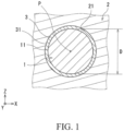
- the sliding member in FIG. 1 includes: a shaft member 1 having a shaft diameter D of greater than or equal to 0.18 m; a bearing member 2 which slidably supports an outer peripheral face 11 of the shaft member 1; and a lubricating oil 3.
- a central axis P of the shaft member 1 extends in a horizontal direction (a Y direction in FIG. 1 ).
- An inner peripheral face 21 of the bearing member 2 surrounds the outer peripheral face 11 of the shaft member 1 along a circumferential direction.
- the lubricating oil 3 is supplied to a gap between the outer peripheral face 11 of the shaft member 1 and the inner peripheral face 21 of the bearing member 2. Furthermore, the lubricating oil 3 forms an oil film 31.
- the bearing member 2 slidably supports the shaft member 1 due to thus being disposed such that the inner peripheral face 21 faces the outer peripheral face 11 with the oil film 31 interposed therebetween.
- the arithmetic mean roughness Ra 1 of the outer peripheral face 11 of the shaft member 1 is less than or equal to 0.23 ⁇ m
- the protruding peak height Rpk 1 of the outer peripheral face 11 of the shaft member 1 is less than or equal to 0.19 ⁇ m.
- a width of the inner peripheral face 21 of the bearing member 2 in an axial direction (the Y direction in FIG. 1 ) is denoted by L [m]
- a width-diameter ratio calculated as L/D is less than 1.
- the parameter C n calculated according to the following formula 1, which represents a state of the oil film, is greater than or equal to the reference value ⁇ ( ⁇ 1 ) calculated based on the following formula 2.
- ⁇ represents a contact rate between the shaft member 1 and the bearing member 2
- ⁇ represents a viscosity [Pa ⁇ sec] of the lubricating oil 3
- N represents a rotation speed [rps] of the shaft member 1
- W represents a maximum load [N] applied from the outer peripheral face 11 of the shaft member 1 to the inner peripheral face 21 of the bearing member 2
- c represents a radius gap [m] between the shaft member 1 and the bearing member 2
- ⁇ ( ⁇ ) represents a roughness parameter of the outer peripheral face 11 of the shaft member 1 and the inner peripheral face 21 of the bearing member 2, the roughness parameter being represented as a function of an eccentricity ⁇
- ⁇ 1 represents a value calculated according to the following formula 3 in a case in which an arithmetic mean roughness of the inner peripheral face of the bearing member 2 is denoted by Ra 2 [ ⁇ m] and a value of a minimum oil film parameter at which the oil film 31 maintains a fluid lubrication state is denoted by ⁇
- arithmetic mean roughness Ra 1 of the outer peripheral face 11 of the shaft member 1 and the arithmetic mean roughness Ra 2 of the inner peripheral face 21 of the bearing member 2 may be used.
- the rotation speed N a rotation speed during steady driving at a time of driving the shaft member 1 may be applied.
- the value ⁇ lim may be set to greater than or equal to 2.0 and less than or equal to 4.0 in accordance with material properties of the shaft member 1 and the bearing member 2.
- the value ⁇ lim of the minimum oil film parameter may be set to 3.0.
- ⁇ lim may be also set to, for example, 2.5.
- ⁇ 1 1 ⁇ ⁇ lim Ra 1 2 + Ra 2 2 c
- the inner peripheral face 21 is subjected to a bearing pressure from the outer peripheral face 11 through the oil film 31. That is to say, the inner peripheral face 21 has a region which is subjected to the bearing pressure (bearing pressure distribution).
- the bearing pressure distribution extends, for example, in the axial direction (the Y direction in FIG. 1 ) of the inner peripheral face 21 and is formed in an arc shape along the inner peripheral face 21 in a section perpendicular to the central axis P.
- a range and a position of the bearing pressure distribution may fluctuate owing to a state of rotation and vibration of the shaft member 1.
- the maximum load W is calculated as a total bearing pressure in the bearing pressure distribution of the inner peripheral face 21.
- the parameter C n is preferably less than the value ⁇ ( ⁇ 2 ) calculated based on the above formula 2 by using the eccentricity ⁇ 2 calculated according to the following formula 4.
- the value ⁇ ( ⁇ 2 ) is calculated based on the eccentricity ⁇ 2 in a sliding member which has a standard surface roughness and in which both the arithmetic mean roughness of the outer peripheral face of the shaft member and the arithmetic mean roughness of the inner peripheral face of the bearing member are 0.40 ⁇ m.
- the parameter C n being less than ⁇ ( ⁇ 2 ) enables controlling the parameter C n to be small.
- the friction loss between the outer peripheral face 11 and the inner peripheral face 21 can be further inhibited.
- ⁇ 2 1 ⁇ 0.32 ⁇ lim c
- the parameter C n is more preferably less than a value ⁇ ( ⁇ 3 ) calculated based on the above formula 2 by using an eccentricity ⁇ 3 calculated according to the following formula 12, and still more preferably less than a value ⁇ ( ⁇ 4 ) calculated based on the above formula 2 by using an eccentricity ⁇ 4 calculated according to the following formula 13.
- the value ⁇ ( ⁇ 3 ) is calculated based on the eccentricity ⁇ 3 in a sliding member in which both the arithmetic mean roughness of the outer peripheral face of the shaft member and the arithmetic mean roughness of the inner peripheral face of the bearing member are 0.35 ⁇ m
- the value ⁇ ( ⁇ 4 ) is calculated based on the eccentricity ⁇ 4 in a sliding member in which both the arithmetic mean roughness of the outer peripheral face of the shaft member and the arithmetic mean roughness of the inner peripheral face of the bearing member are 0.30 ⁇ m.
- ⁇ 3 1 ⁇ 0.245 ⁇ lim c
- ⁇ 4 1 ⁇ 0.18 ⁇ lim c
- the shaft member 1 is a rotating body which rotates in the circumferential direction with respect to the bearing member 2.
- the shaft member 1 is exemplified by a crankshaft, an intermediate shaft, a propulsion shaft, and the like for a ship, each of which is to be disposed in a ship.
- Examples of a material of the shaft member 1 include carbon steel, low-alloy steel, an aluminum alloy, and the like.
- a coating layer such as a lubricating film or the like is not formed on the outer peripheral face 11 of the shaft member 1.
- the lower limit of the shaft diameter D of the shaft member 1 is 0.18 m as described above, may be 0.28 m, may be 0.33 m, and may be 0.36 m.
- the coating layer is provided on the outer peripheral face 11 of the shaft member 1 and/or the like in a case in which the shaft diameter D of the shaft member 1 is greater than or equal to the lower limit value, there is a high possibility that the coating layer may be damaged, thereby generating impurities.
- the sliding member does not require the coating layer to be provided on the outer peripheral face 11; therefore, mixture of impurities in the sliding area can be inhibited.
- the upper limit of the shaft diameter D of the shaft member 1 is not particularly limited and is, for example, preferably 1.5 m, more preferably 1.3 m, and still more preferably 1.2 m.
- the shaft diameter D of the shaft member 1 is greater than the upper limit value, there may be a possibility that the friction loss between the outer peripheral face 11 and the inner peripheral face 21 cannot be sufficiently inhibited.
- the lower limit of the contact rate ⁇ is preferably 0.6, more preferably 0.7, and still more preferably 0.8.
- the contact rate ⁇ can be increased to be greater than or equal to the lower limit.
- a method for determining the contact part and the contact rate ⁇ is exemplified by a method of using a straight edge, a method of using a bearing model having a shell shape, and the like.
- the straight edge has a plane which extends in an axial direction of the shaft member.
- ink is applied to the plane, and then the plane is pressed against the outer peripheral face of the shaft member to transfer the ink thereonto.
- the contact part is determined by a part onto which the ink has transferred, and the contact rate ⁇ is determined by a transfer rate of the ink.
- the bearing model having a shell shape has an inner peripheral face which partly surrounds the outer peripheral face of the shaft member.
- the contact part and the contact rate ⁇ are also determined in such a manner that, as in the method of using the straight edge, ink is applied to the inner peripheral face, and then the inner peripheral face is pressed against the outer peripheral face of the shaft member to transfer the ink thereonto.
- the contact rate ⁇ is less than the lower limit, uniform contact between the outer peripheral face 11 of the shaft member 1 and the inner peripheral face 21 of the bearing member 2 may be difficult.
- the bearing pressure from the outer peripheral face 11 to the inner peripheral face 21 due to the maximum load W is likely to increase, and thus it may be difficult for the oil film 31 to maintain the fluid lubrication state.
- a plurality of roughness projection apices may be present, wherein the roughness projection apices are calculated by the following procedure. Firstly, based on a roughness curve with a measured length of 4.0 mm, the roughness curve being measured at a cut-off value of 0.25 mm according to JIS-B0601 (2013), an average line of the roughness curve is set according to JIS-B0601 (2013). With the average line as a reference, heights of measurement points above the average line are defined as positive values, while heights of measurement points below the average line are defined as negative values. An average value of the heights of all the measurement points having positive values is denoted by Thr0.
- a measurement point which is higher than measurement points adjacent thereto on both sides and has a height of greater than -Thr0 is defined as a temporary apex.
- a measurement point having a smallest height (having a largest depth from the temporary apices adjacent to each other) is defined as a valley.
- height differences between a temporary apex and each of valleys adjacent to the temporary apex on both sides are respectively determined, and apices in which the larger value of these height differences is less than 0.2 ⁇ Thr0 are excluded.
- remaining temporary apices are determined as roughness projection apices.
- the lower limit of a radius of curvature ⁇ of roughness projections on the outer peripheral face 11 may be 55 ⁇ m, and may be 58 ⁇ m.
- the radius of curvature ⁇ of roughness projections is likely to increase.
- seizure is likely to occur between the outer peripheral face 11 and the inner peripheral face 21. Even with such a configuration, the sliding member enables easy inhibition of seizure in the sliding area.
- the "radius of curvature of roughness projections" as referred to herein means a value calculated by the following procedure. Firstly, straight lines are drawn toward the roughness projection apex from all measurement points between the roughness projection apex and valleys adjacent to the roughness projection apex on both sides, and the measurement point for which the slope of the straight line is the largest is defined as an end of the roughness projection.
- the radius of curvature of each roughness projection is determined by -0.5/a, wherein a denotes a quadratic coefficient of a quadratic function obtained by approximating a roughness curve between both ends of each roughness projection by the method of least squares.
- a median of the radii of curvature of all the roughness projections on the roughness curve is determined as the radius of curvature of the roughness projections.
- the shaft member 1 When the outer peripheral face 11 is manually polished as the above-mentioned finish processing, the shaft member 1 is likely to have a large radius of curvature ⁇ of roughness projections. Furthermore, with regard to other roughness characteristics of the outer peripheral face 11, the degree of roughness also tends to increase. In this case, by polishing with sandpaper having a sufficiently large grit number, the arithmetic mean roughness Ra 1 of outer peripheral face 11 of the shaft member 1 can be reduced to less than or equal to 0.23 ⁇ m, and the protruding peak height Rpk 1 of the outer peripheral face 11 can be reduced to less than or equal to 0.19 ⁇ m.
- the arithmetic mean roughness Ra 1 and the protruding peak height Rpk 1 can be reduced to fall within the above ranges.
- the grit number of the sandpaper may be greater than 500, and may be greater than 600. It is to be noted that the arithmetic mean roughness Ra 1 of the outer peripheral face 11 of the shaft member 1 and the protruding peak height Rpk 1 of the outer peripheral face 11 may be values after the above-described polishing with the sandpaper and before sliding between the shaft member 1 and the bearing member 2.
- the upper limit of the arithmetic mean roughness Ra 1 of the outer peripheral face 11 is 0.23 ⁇ m as described above, preferably 0.16 ⁇ m, more preferably 0.12 ⁇ m, and still more preferably 0.08 ⁇ m.
- the lower limit of the arithmetic mean roughness Ra 1 of the outer peripheral face 11 is not particularly limited and may be 0.01 ⁇ m. It is to be noted that as the arithmetic mean roughness Ra 1 of the outer peripheral face 11, a value before sliding between the shaft member 1 and the bearing member 2 may be used.
- the upper limit of the protruding peak height Rpk 1 of the outer peripheral face 11 is 0.19 ⁇ m as described above, preferably 0.18 ⁇ m, more preferably 0.14 ⁇ m, and still more preferably 0.10 ⁇ m.
- the lower limit of the protruding peak height Rpk 1 of the outer peripheral face 11 is not particularly limited and may be 0.01 ⁇ m. It is to be noted that as the protruding peak height Rpk 1 of the outer peripheral face 11, a value before sliding between the shaft member 1 and the bearing member 2 may be used.
- the bearing member 2 is exemplified by a crank bearing, an intermediate bearing, a propulsion bearing, and the like for a ship, each of which is to be disposed in a ship.
- Examples of a material of the bearing member 2 include white metal, an aluminum alloy, trimetal, kelmet, and the like.
- a coating layer such as a lubricating film or the like is not formed on the inner peripheral face 21 of the bearing member 2.
- the upper limit of the width L of the inner peripheral face 21 of the bearing member 2 in the axial direction is preferably 0.350 m, more preferably 0.300 m, and still more preferably 0.220 m.
- the width L is greater than the upper limit, there may be a possibility that the friction loss between the outer peripheral face 11 and the inner peripheral face 21 cannot be sufficiently inhibited.
- the lower limit of the width L may be, for example, 0.010 m.
- the upper limit of the width-diameter ratio calculated as L/D is less than 1 as described above, preferably 0.8, more preferably 0.6, and still more preferably 0.4.
- a calculated value of the parameter C n is less likely to be coincident with the state of the oil film 31, and thus there may be a possibility that the friction loss between the outer peripheral face 11 and the inner peripheral face 21 cannot be sufficiently inhibited.
- the lower limit of the width-diameter ratio may be, for example, 0.1.
- the upper limit of the radius gap c is not particularly limited and may be, for example, 1.0 ⁇ 10 -3 m. In light of facilitating formation of the oil film, the lower limit of the radius gap c may be, for example, 1.0 ⁇ 10 -4 m.
- the outer peripheral face 11 and the inner peripheral face 21 differ in hardness.
- the outer peripheral face 11 and the inner peripheral face 21 differ in hardness, in a case in which the outer peripheral face 11 comes into contact with the inner peripheral face 21, microscopic projections on a surface having a higher hardness of two sliding faces are likely to be maintained.
- a surface having a lower hardness is easily plastically deformed due to rotation contact between the sliding faces.
- the peripheral face having a lower hardness can be regarded as a surface having substantially the same level of roughness projections as the peripheral face having a higher hardness, or as a smooth surface having substantially no roughness projections.
- the sliding face having a lower hardness as a surface having the same level of roughness projections as the sliding face having a higher hardness, or as a smooth surface having no roughness projections can be calculated more easily.
- the hardness H 1 [HV] of the shaft member 1 is preferably higher than the hardness H 2 [HV] of the bearing member 2.
- the hardness H 2 of the bearing member 2 is low, it is difficult to intentionally control the surface roughness of the inner peripheral face 21 by mechanical processing and/or the like.
- the inner peripheral face 21 of the bearing member 2 can be polished owing to the sliding with the shaft member 1.
- the surface roughness of the inner peripheral face 21 of the bearing member 2 is reduced, and thus the frictional resistance and the seizure between the outer peripheral face 11 and the inner peripheral face 21 are easily inhibited.
- the lower limit of a ratio (H 1 /H 2 ) of the hardness H 1 of the shaft member 1 to the hardness H 2 of the bearing member 2 is preferably 4.1, more preferably 5.0, still more preferably 6.0, and particularly preferably 8.0.
- the upper limit of the above ratio is not particularly limited and may be, for example, 20 in light of ease of selection of materials of the shaft member 1 and the bearing member 2, and the like.
- the lubricating oil 3 is exemplified by paraffin base oil and the like. By forming the oil film 31, the lubricating oil 3 facilitates maintaining the fluid lubrication state between the outer peripheral face 11 and the inner peripheral face 21.
- the upper limit of the viscosity ⁇ of the lubricating oil 3 is preferably 7.7 ⁇ 10 -3 Pa ⁇ sec, more preferably 6.2 ⁇ 10 -3 Pa ⁇ sec, and still more preferably 5.2 ⁇ 10 -3 Pa ⁇ sec.
- the viscosity ⁇ is greater than the upper limit, there may be a possibility that the friction loss between the outer peripheral face 11 and the inner peripheral face 21 cannot be sufficiently inhibited.
- the lower limit of the viscosity ⁇ may be, for example, 1.0 ⁇ 10 -3 Pa ⁇ sec.
- the sliding member Since the oil film 31 easily maintains the fluid lubrication state, the sliding member enables inhibition of the friction loss and the seizure between the outer peripheral face 11 and the inner peripheral face 21. Moreover, in the sliding member, since the viscosity ⁇ , the rotation speed N, the width L, and the shaft diameter D are easily controlled to be small, the friction loss is easily reduced under the condition under which the oil film 31 is in the fluid lubrication state.
- the method for driving a sliding member in FIG. 2 includes a driving step S1 of driving by using the sliding member in FIG. 1 to rotate the shaft member 1.
- the shaft member 1 is rotated while the lubricating oil 3 is supplied to the gap between the shaft member 1 and the bearing member 2.
- a method for supplying the lubricating oil 3 is exemplified by a method in which a supply port for supplying the lubricating oil 3 is provided on the inner peripheral face 21 of the bearing member 2 and the lubricating oil 3 is supplied from the supply port such that the lubricating oil 3 circulates in the sliding area between the shaft member 1 and the bearing member 2.
- the parameter C n calculated according to the above formula 1, which represents the state of the oil film 31, is controlled to be greater than or equal to the reference value ⁇ ( ⁇ 1 ) calculated based on the above formula 2.
- the lower limit of the rotation speed N is preferably 0.30 rps and more preferably 0.56 rps.
- the upper limit of the rotation speed N is preferably 30 rps and more preferably 20 rps.
- the rotation speed N is greater than the upper limit, there may be a possibility that the friction loss between the outer peripheral face 11 and the inner peripheral face 21 cannot be sufficiently inhibited.
- the friction loss and the seizure between the shaft member 1 and the bearing member 2 can be inhibited.
- the central axis of the shaft member extends in the horizontal direction; however, the central axis of the shaft member may be inclined to the horizontal direction.
- the outer peripheral face of the shaft member and the inner peripheral face of the bearing member differ in hardness; however, the hardness of the outer peripheral face may be substantially equal to that of the inner peripheral face.
- ⁇ 1 is preferably calculated according to the above formula 3 by using the respective arithmetic mean roughnesses of the outer peripheral face and the inner peripheral face.
- the shaft member is rotated while the lubricating oil is supplied to the gap between the shaft member and the bearing member; however, the lubricating oil may be dropped into the gap before rotation of the shaft member. Furthermore, in the case in which the lubricating oil is dropped into the gap before rotation of the shaft member, it is not necessary for the lubricating oil to be dropped during rotation of the shaft member.
- shaft members having various degrees of roughness were rotated using a bearing lifetime tester available from Chihoda-Seiko Co., Ltd.
- a shaft member with a manually polished outer peripheral face was used as each of the shaft members.
- the shaft member was rotated while the inner peripheral face of the bearing member which surrounded the entire periphery of the outer peripheral face of the shaft member was pressed against the shaft member with a constant load.
- the shaft diameter of the shaft member was 39.96 mm (tolerance: ⁇ 0.01 mm)
- an inner diameter of the bearing member was 40.20 mm (tolerance: +0.025 mm to +0.050 mm)
- the width of the inner peripheral face of the bearing member in the axial direction was 35.00 mm.
- the load from the bearing member to the shaft member was set to 10 kN.
- the rotation speed of the shaft member was decreased in stages by 250 rpm at intervals of greater than or equal to 1 minute and less than or equal to 10 minutes from an initial rotation speed of 3,000 rpm to a minimum rotation speed of 250 rpm.
- the rotation of the shaft member was stopped at a time of occurrence of seizure between the outer peripheral face of the shaft member and the inner peripheral face of the bearing member.
- Manganese steel was used as the shaft member, and white metal of WJ1 as defined in JIS-H5401 (1958) was used as the bearing member.
- As the lubricating oil "FBK oil RO32", available from ENEOS Corporation, was used.
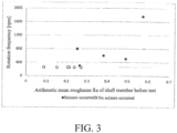
- FIG. 3 shows a relationship between the arithmetic mean roughness Ra of the outer peripheral face of the shaft member and the rotation speed of the shaft member at the time of occurrence of the seizure
- FIG. 4 shows a relationship between the protruding peak height Rpk of the outer peripheral face of the shaft member and the rotation speed of the shaft member at the time of occurrence of the seizure.
- FIG. 3 shows a relationship between the arithmetic mean roughness Ra of the outer peripheral face of the shaft member and the rotation speed of the shaft member at the time of occurrence of the seizure
- FIG. 4 shows a relationship between the protruding peak height Rpk of the outer peripheral face of the shaft member and the rotation speed of the shaft member at the time of occurrence of the seizure.
- FIG. 3 shows a relationship between the arithmetic mean roughness Ra of the outer peripheral face of the shaft member and the rotation speed of the shaft member at the time of occurrence of the seizure
- FIG. 4 shows a relationship between the protrud
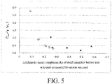
- FIG. 5 shows a relationship between the arithmetic mean roughness of the shaft member and C n / ⁇ ( ⁇ 1 ) at the time of occurrence of the seizure.
- each white circle means that no seizure occurred, while each black circle means that seizure occurred.
- C n in FIG. 5 was calculated according to the above formula 1, wherein the load W applied to the inner peripheral face of the bearing member was set to 1.0 ⁇ 10 4 N, the contact rate ⁇ was set to 1, and the rotation speed N of the shaft member was defined as a rotation frequency at the time when the rotation of the shaft member was stopped; ⁇ ( ⁇ 1 ) in FIG.
- seizure is likely to occur in a case in which C n / ⁇ ( ⁇ 1 ) is less than 1.
- C n / ⁇ ( ⁇ 1 ) is less than 1.
- the outer peripheral face of the shaft member was polished with sandpaper.
- steel corresponding to S45C as defined in JIS-G4051 (2016) was used as a material of the shaft member.
- the shaft diameter of the shaft member in a part to be polished was set to 600 mm.
- the polishing was repeatedly performed while the grit number of the sandpaper was gradually increased.
- the arithmetic mean roughness Ra and the protruding peak height Rpk of the outer peripheral face after the polishing were measured using the portable surface roughness measurement instrument ("SJ-310"), available from Mitutuyo Corporation.
- FIG. 6 shows measurement results of the arithmetic mean roughness Ra 1
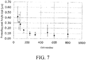
- FIG. 7 shows measurement results of the protruding peak height Rpk 1 . It is to be noted that in FIGs. 6 and 7 , each dot represents an average value, and a corresponding error bar represents an error range with respect to the average value.
- the arithmetic mean roughness Ra is reduced to a range of less than or equal to 0.23 ⁇ m.
- the protruding peak height Rpk of the outer peripheral face of the shaft member tends to be reduced to a range of less than or equal to 0.19 ⁇ m.
- the protruding peak height Rpk of the outer peripheral face of the shaft member is reduced to the range of less than or equal to 0.19 ⁇ m.
- the degree of roughness of the outer peripheral face of the shaft member can be controlled to fall within a range in which seizure is less likely to occur in the above-described seizure test.
- the shaft member was rotated under the following conditions of No. 1 to No. 20 by using an apparatus A (a frictional wear tester available from Chihoda-Seiko Co., Ltd.), an apparatus B (the bearing lifetime tester available from Chihoda-Seiko Co., Ltd.), and an apparatus C (a frictional wear tester available from KOBELCO MACHINERY ENGINEERING Co., Ltd.).
- an apparatus A a frictional wear tester available from Chihoda-Seiko Co., Ltd.
- an apparatus B the bearing lifetime tester available from Chihoda-Seiko Co., Ltd.
- an apparatus C a frictional wear tester available from KOBELCO MACHINERY ENGINEERING Co., Ltd.
- the shaft member was rotated while the inner peripheral face of the bearing member which surrounded the entire periphery of the outer peripheral face of the shaft member was pressed against the shaft member with a constant load.
- the apparatus B was identical to the bearing lifetime tester used in the above-described seizure test.
- the hardnesses of the shaft member and the bearing member as well as the arithmetic mean roughnesses and the protruding peak heights of the shaft member and the bearing member before and after the sliding test were measured. Table 1 shows measurement results of No. 1 to No. 20.
- Ra 1A denotes the arithmetic mean roughness of the shaft member before the sliding test
- Ra 1B denotes the arithmetic mean roughness of the shaft member after the sliding test
- Ra 2A denotes the arithmetic mean roughness of the bearing member before the sliding test
- Ra 2B denotes the arithmetic mean roughness of the bearing member after the sliding test.
- Rpk 1A denotes the protruding peak height of the shaft member before the sliding test
- Rpk 1B denotes the protruding peak height of the shaft member after the sliding test
- Rpk 2A denotes the protruding peak height of the bearing member before the sliding test
- Rpk 2B denotes the protruding peak height of the bearing member after the sliding test.
- FV-310 Vickers hardness meter
- MVK-E Vickers hardness meter
- the arithmetic mean roughness and the protruding peak height were measured using the portable surface roughness measurement instrument ("SJ-310"), available from Mitutuyo Corporation. Furthermore, in the measurement of the arithmetic mean roughness and the protruding peak height, the evaluation length was set to 4 mm.
- the load from the bearing member to the shaft member was set to 10 kN.
- the rotation speed of the shaft member was decreased in stages by 250 rpm at intervals of 10 minutes from the initial rotation speed of 3,000 rpm to the minimum rotation speed of 250 rpm.
- Manganese steel was used as the shaft member, and white metal of WJ1 as defined in JIS-H5401 (1958) was used as the bearing member.
- As the lubricating oil "FBK oil RO32", available from ENEOS Corporation, was used. The lubricating oil was supplied to the sliding area between the outer peripheral face of the shaft member and the inner peripheral face of the bearing member at the initial temperature of 70 °C and was circulated while the sliding area was immersed in the lubricating oil.
- the rotation speed of the shaft member was set to a constant value of 3,500 rpm.
- the load from the bearing member to the shaft member was increased in stages by 0.5 kN at intervals of 5 minutes from an initial load of 0 kN to a maximum of 20 kN.
- Manganese steel was used as the shaft member, and white metal corresponding to WJ1 as defined in JIS-H5401 (1958) was used as the bearing member.
- As the lubricating oil "FBK oil RO32", available from ENEOS Corporation, was used. The lubricating oil was supplied to the sliding area between the outer peripheral face of the shaft member and the inner peripheral face of the bearing member at the initial temperature of 70 °C and was circulated in the sliding area.
- the rotation speed of the shaft member was set to 400 rpm.
- the load from the bearing member to the shaft member was increased in stages by 0.1 kN at intervals of 1 minute from the initial load of 0 kN, to 1 kN.
- Steel of S45C as defined in JIS-G4051 (2016) was used as the shaft member, and white metal of WJ2 as defined in JIS-H5401 (1958) was used as the bearing member.
- As the lubricating oil "FBK oil RO32", available from ENEOS Corporation, was used. The lubricating oil was supplied to the sliding area between the outer peripheral face of the shaft member and the inner peripheral face of the bearing member at room temperature and was circulated in the sliding area.
- the rotation speed of the shaft member was set to 400 rpm.
- a configuration and driving conditions of No. 16 were similar to those of No. 13 except for the rotation speed of the shaft member.
- a configuration of each of No. 19 and No. 20 was similar to that of No. 1 to No. 3 except that nickel-chromium-molybdenum alloy steel was used as the shaft member. Furthermore, driving conditions of No. 19 and No. 20 were similar to those of No. 1 to No. 3 except that the rotation speed of the shaft member was decreased at intervals of 1 minute. Table 1 No.
- Apparatus Hardness H 1 /H 2
- Arithmetic mean roughness [ ⁇ m] Protruding peak height [ ⁇ m] shaft member H 1 bearing member H 2 shaft member bearing member shaft member bearing member Ra 1A before test Ra 1B after test Ra 2A before test Ra 2B after test Rpk 1A before test Rpk 1B after test Rpk 1A before test Rpk 2B after test 1
- B 212.8 24.9 8.5 0.09 0.09 0.96 0.46 0.08 0.10 2.29 0.27 2
- the arithmetic mean roughness and the protruding peak height of the shaft member did not significantly change before and after the sliding test.
- the arithmetic mean roughness and the protruding peak height of the bearing member tended to decrease after the sliding test.
- FIG. 8 shows a graph in which the horizontal axis represents the ratio (H 1 /H 2 ) of the hardness H 1 [HV] of the shaft member to the hardness H 2 [HV] of the bearing member, and the vertical axis represents a difference in arithmetic mean roughness Ra 2B - Ra 1B after the sliding test.
- FIG. 9 shows a graph in which the horizontal axis represents H 1 /H 2 , and the vertical axis represents a difference in protruding peak height Rpk 2B - Rpk 1B .
- each dot in FIGs. 8 and 9 represents an average value, and a corresponding error bar represents an error range with respect to the average value. It is to be noted that with regard to No. 13 to No. 15, an average value of the values of H 1 /H 2 was obtained, and is shown as the data in which the value of H 1 /H 2 is 5.2.
- the parameter C n was calculated according to the above formula 1
- the eccentricity ⁇ 1 was calculated according to the above formula 3
- the eccentricity ⁇ 2 was calculated according to the above formula 4
- the reference values ⁇ ( ⁇ 1 ) and ⁇ ( ⁇ 2 ) were calculated by applying the eccentricity ⁇ 1 and the eccentricity ⁇ 2 to the above formula 2
- the limit oil film thickness h lim was calculated according to the following formula 14
- the friction coefficient ⁇ was calculated according to the above formula 6.
- the oil film parameter ⁇ lim was set to 3.0.
- the "limit oil film thickness" as referred to herein means a minimum oil film thickness at which the oil film can maintain the fluid lubrication state.
- the shaft diameter D of each of No. 21 to No. 26 is 0.90 m.
- the rotation speed N of No. 22 is controlled to be lower than that of the conventional sliding member (No. 21)
- the arithmetic mean roughnesses of the outer peripheral face of the shaft member and the inner peripheral face of the bearing member of No. 22 are both 0.40 ⁇ m, which are equal to those of No. 21. Accordingly, C n / ⁇ ( ⁇ 1 ) of No. 22 is less than 1, and thus there may be a possibility that No. 22 cannot maintain the fluid lubrication state.
- the bearing width L of each of No. 27 to No. 29 is 0.200 m.
- the shaft diameter D and the viscosity ⁇ of the lubricating oil of No. 28 are controlled to be smaller than those of the conventional sliding member (No. 27)
- the arithmetic mean roughnesses of the outer peripheral face of the shaft member and the inner peripheral face of the bearing member of No. 28 are both 0.40 ⁇ m, being equal to those of No. 27. Accordingly, C n / ⁇ ( ⁇ 1 ) of No. 28 is less than 1, and thus there may be a possibility that No. 28 cannot maintain the fluid lubrication state.
- the shaft diameter D of each of No. 30 to No. 32 is 0.18 m.
- the bearing width L of No. 31 is controlled to be smaller than that of the conventional sliding member (No. 30)
- the arithmetic mean roughnesses of the outer peripheral face of the shaft member and the inner peripheral face of the bearing member of No. 31 are both 0.40 ⁇ m, being equal to those of No. 30. Accordingly, C n / ⁇ ( ⁇ 1 ) of No. 31 is less than 1, and thus there may be a possibility that No. 31 cannot maintain the fluid lubrication state.
- a sliding member in which ⁇ ( ⁇ 1 ) ⁇ C n ⁇ ⁇ ( ⁇ 2 ) is satisfied enables inhibition of the friction loss as compared with a conventional sliding member, while maintaining the fluid lubrication state.
- the sliding member according to the one aspect of the present invention enables inhibition of the frictional resistance and the seizure between the shaft member and the bearing member and can be thus applied to, for example, a sliding member for a ship.
Landscapes
- Engineering & Computer Science (AREA)
- General Engineering & Computer Science (AREA)
- Mechanical Engineering (AREA)
- Sliding-Contact Bearings (AREA)
- Shafts, Cranks, Connecting Bars, And Related Bearings (AREA)
Abstract
Description
- The present invention relates to a sliding member and a method for driving a sliding member.
- A sliding member for a ship includes: for example, a shaft member such as a crankshaft, an intermediate shaft, a propulsion shaft, or the like; and a bearing member such as a slide bearing or the like which slidably supports the shaft member. Furthermore, lubricating oil is supplied to a gap between the shaft member and the bearing member. The lubricating oil forms an oil film between the shaft member and the bearing member to inhibit frictional resistance between these members.
- In a case in which a thickness of the oil film relative to surface roughness of a sliding face is sufficient (in a case of a fluid lubrication state), a main factor of the frictional resistance is a viscosity of the oil film, and thus low frictional resistance tends to be maintained. On the other hand, in a case in which the thickness of the oil film relative to the surface roughness of the sliding face is insufficient, not only the viscosity of the oil film but also a solid contact between the shaft member and the bearing member may become a factor of the frictional resistance, and thus the frictional resistance is likely to increase. Furthermore, in the case in which the thickness of the oil film is insufficient, seizure is likely to occur on the sliding face. Therefore, by forming a favorable oil film, a friction loss and seizure on the sliding face can be effectively inhibited.
- As a technique for inhibiting the friction loss of the sliding member, for example,
Patent Document 1 discloses a crank lubrication system for reducing a friction loss of a crankshaft. As a technique for inhibiting the friction loss and the seizure of the sliding member,Patent Document 2 discloses a simple processing method of a rotary shaft having a lubricating oil-retaining function. -
- Patent Document 1:
Japanese Unexamined Patent Application, Publication No. H8-121485 - Patent Document 2:
Japanese Unexamined Patent Application, Publication No. H7-116958 - However, in the crank lubrication system disclosed in
Patent Document 1, a temperature of the lubricating oil is likely to rise owing to a high degree of surface roughness of a crankpin, and thus there may be a possibility that the seizure cannot be sufficiently inhibited. - In producing a large sliding member for a ship, it may be difficult to realize sufficient dimensional accuracy only by mechanical processing. Particularly in a case of a sliding member having a crankshaft for a ship, a crankpin is eccentric to a journal, and thus the dimensional accuracy of the sliding face after the mechanical processing is likely to be insufficient. Therefore, the large sliding member for a ship tends to require manual polishing of the sliding face of the shaft member as finish processing. Meanwhile, the processing method disclosed in
Patent Document 2 requires roll burnishing as finish processing, and thus there may be a possibility that the processing method cannot be applied to the large sliding member for a ship. - The present invention was made in view of the foregoing circumstances, and an object of the present invention is to provide a sliding member which enables inhibition of a friction loss and seizure between a shaft member and a bearing member.
- A sliding member according to one aspect of the present invention made to solve the aforementioned problems includes: a shaft member having a shaft diameter D of greater than or equal to 0.18 m; a bearing member which slidably supports an outer peripheral face of the shaft member; and a lubricating oil which is supplied to a gap between the outer peripheral face of the shaft member and an inner peripheral face of the bearing member and forms an oil film in the gap, wherein an arithmetic mean roughness Ra1 of the outer peripheral face of the shaft member is less than or equal to 0.23 µm, and a protruding peak height Rpk1 of the outer peripheral face of the shaft member is less than or equal to 0.19 µm, in a case in which a width of the inner peripheral face of the bearing member in an axial direction is denoted by L [m], a width-diameter ratio calculated as L/D is less than 1, and a parameter Cn calculated according to the following
formula 1, which represents a state of the oil film, is greater than or equal to a reference value γ(ε1) calculated based on thefollowing formula 2.


- In the
above formula 1, α represents a contact rate between the shaft member and the bearing member, η represents a viscosity [Pa·sec] of the lubricating oil, N represents a rotation speed [rps] of the shaft member, W represents a maximum load [N] applied from the outer peripheral face of the shaft member to the inner peripheral face of the bearing member, and c represents a radius gap [m] between the shaft member and the bearing member; in theabove formula 2, γ(ε) represents a roughness parameter of the outer peripheral face of the shaft member and the inner peripheral face of the bearing member, the roughness parameter being represented as a function of an eccentricity ε; and ε1 represents a value calculated according to the followingformula 3 in a case in which an arithmetic mean roughness of the inner peripheral face of the bearing member is denoted by Ra2 [µm] and a value of a minimum oil film parameter at which the oil film maintains a fluid lubrication state is denoted by Λlim.

- The sliding member according to the one aspect of the present invention enables inhibition of the friction loss and the seizure between the shaft member and the bearing member.
-
-
FIG. 1 is a schematic cross-sectional view illustrating a section perpendicular to a central axis of a shaft member in a sliding member according to one embodiment of the present invention. -
FIG. 2 is a flowchart illustrating a method for driving a sliding member according to an other embodiment of the present invention. -
FIG. 3 is a graph showing a relationship between an arithmetic mean roughness of the shaft member and a rotation speed of the shaft member at a time of occurrence of seizure. -
FIG. 4 is a graph showing a relationship between a protruding peak height of the shaft member and the rotation speed of the shaft member at the time of occurrence of the seizure. -
FIG. 5 is a graph showing a relationship between the arithmetic mean roughness of the shaft member and Cn/γ(ε1) at the time of occurrence of the seizure. -
FIG. 6 is a graph showing a relationship between a grit number of sandpaper with which the shaft member was polished, and the arithmetic mean roughness of the shaft member. -
FIG. 7 is a graph showing a relationship between the grit number of the sandpaper with which the shaft member was polished, and the protruding peak height of the shaft member. -
FIG. 8 is a graph showing a relationship between a hardness ratio of the shaft member to a bearing member, and a difference in arithmetic mean roughness between the bearing member and the shaft member after a sliding test. -
FIG. 9 is a graph showing a relationship between the hardness ratio of the shaft member to the bearing member, and a difference in protruding peak height between the bearing member and the shaft member after the sliding test. - Firstly, embodiments of the present invention are listed and described.
- A sliding member according to one aspect of the present invention made to solve the aforementioned problems includes: a shaft member having a shaft diameter D of greater than or equal to 0.18 m; a bearing member which slidably supports an outer peripheral face of the shaft member; and a lubricating oil which is supplied to a gap between the outer peripheral face of the shaft member and an inner peripheral face of the bearing member and forms an oil film in the gap, wherein an arithmetic mean roughness Ra1 of the outer peripheral face of the shaft member is less than or equal to 0.23 µm, and a protruding peak height Rpk1 of the outer peripheral face of the shaft member is less than or equal to 0.19 µm, in a case in which a width of the inner peripheral face of the bearing member in an axial direction is denoted by L [m], a width-diameter ratio calculated as L/D is less than 1, and a parameter Cn calculated according to the following
formula 1, which represents a state of the oil film, is greater than or equal to a reference value γ(ε1) calculated based on thefollowing formula 2.


- In the
above formula 1, α represents a contact rate between the shaft member and the bearing member, η represents a viscosity [Pa·sec] of the lubricating oil, N represents a rotation speed [rps] of the shaft member, W represents a maximum load [N] applied from the outer peripheral face of the shaft member to the inner peripheral face of the bearing member, and c represents a radius gap [m] between the shaft member and the bearing member; in theabove formula 2, γ(ε) represents a roughness parameter of the outer peripheral face of the shaft member and the inner peripheral face of the bearing member, the roughness parameter being represented as a function of an eccentricity ε; and ε1 represents a value calculated according to the followingformula 3 in a case in which an arithmetic mean roughness of the inner peripheral face of the bearing member is denoted by Ra2 [µm] and a value of a minimum oil film parameter at which the oil film maintains a fluid lubrication state is denoted by Λlim.

- The sliding member enables inhibition of a friction loss and seizure between the shaft member and the bearing member for the following reasons. In general, a condition under which the oil film between the shaft member and the bearing member can maintain the fluid lubrication state is represented by the following formula 5 by using a Dubois-Ocvirk approximate expression in a case in which the width-diameter ratio is less than 1. In a sliding member including a shaft member having a large diameter, it is difficult to increase the dimensional accuracy, and thus the contact rate between the shaft member and the bearing member is less than 1. Furthermore, it is typical to set a safety factor in design of a machine structure. Thus, in the sliding member, the oil film easily maintains the fluid lubrication state owing to the parameter Cn, which is obtained by multiplying the left side of the following formula 5 by the contact rate α (< 1) between the shaft member and the bearing member, being greater than or equal to the reference value γ(ε1), which is obtained by multiplying the right side of the following formula 5 by the safety factor of 3. Furthermore, in the sliding member, since the arithmetic mean roughness Ra1 and the protruding peak height Rpk1 of the shaft member are controlled to be less than or equal to certain values, the reference value γ(ε1) can be reduced. Thus, for example, even in a case in which the maximum load W is high, the parameter Cn tends to be greater than or equal to the reference value γ(ε1); therefore, the oil film easily maintains the fluid lubrication state. Furthermore, even in a case in which the viscosity η, the rotation speed N, the width L, and the shaft diameter D are controlled to be small, the oil film likewise easily maintains the fluid lubrication state. Accordingly, the sliding member enables inhibition of the friction loss and the seizure.

- Moreover, a friction coefficient µ between the shaft member and the bearing member under the condition under which the oil film is in the fluid lubrication state is represented by the following
formula 6. Referring to the followingformula 6, the friction coefficient µ is decreased by reducing the viscosity η, the rotation speed N, the width L, and the shaft diameter D. As described above, in the sliding member, since the viscosity η, the rotation speed N, the width L, and the shaft diameter D are easily controlled to be small, the friction loss under the condition under which the oil film is in the fluid lubrication state is easily reduced.

- It is preferred that the outer peripheral face of the shaft member and the inner peripheral face of the bearing member differ in hardness, and that with regard to a peripheral face having a higher hardness, the peripheral face being one of the outer peripheral face of the shaft member and the inner peripheral face of the bearing member, in a case in which an arithmetic mean roughness thereof is denoted by Rah [µm], Ra1 = Ra2 = Rah is satisfied in the
above formula 3. In a case in which the outer peripheral face of the shaft member is continuously in contact with the inner peripheral face of the bearing member, microscopic projections on the surface having the higher hardness of these peripheral faces tend to be maintained. In contrast, it is considered that when a surface having the lower hardness of these peripheral faces is polished with the surface having the higher hardness thereof, a surface roughness of the surface having the lower hardness approaches that of the surface having the higher hardness. Therefore, with regard to the peripheral face having the higher hardness, the peripheral face being one of the outer peripheral face of the shaft member and the inner peripheral face of the bearing member, by using the arithmetic mean roughness Rah thereof such that Ra1 = Ra2 = Rah is satisfied in theabove formula 3, the reference value γ(ε1) can be calculated more easily. - The contact rate α is preferably greater than or equal to 0.6. In a sliding member including a shaft member having a large diameter, it is difficult to sufficiently increase the contact rate between the shaft member and the bearing member only by mechanical processing, and the contact rate is increased by manually polishing the outer peripheral face of the shaft member as finish processing. By thus increasing the contact rate α, the outer peripheral face of the shaft member tends to be uniformly in contact with the inner peripheral face of the bearing member. As a result, the maximum load W is reduced, whereby the fluid lubrication state is easily maintained.
- The parameter Cn is preferably less than a value γ(ε2) calculated based on the
above formula 2 by using an eccentricity ε2 calculated according to the following formula 4. Thus, the parameter Cn being less than γ(ε2) enables sufficient inhibition of the friction loss between the shaft member and the bearing member.

- An other aspect of the present invention is a method for driving a sliding member including: a shaft member having a shaft diameter D of greater than or equal to 0.18 m; a bearing member which slidably supports an outer peripheral face of the shaft member; and a lubricating oil which is supplied to a gap between the outer peripheral face of the shaft member and an inner peripheral face of the bearing member and forms an oil film in the gap, the method including: a driving step of driving by using the sliding member to rotate the shaft member, wherein an arithmetic mean roughness Ra1 of the outer peripheral face of the shaft member is less than or equal to 0.23 µm, and a protruding peak height Rpk1 of the outer peripheral face of the shaft member is less than or equal to 0.19 µm, in a case in which a width of the inner peripheral face of the bearing member in an axial direction is denoted by L [m], a width-diameter ratio calculated as L/D is less than 1, and during steady driving in the driving step, a parameter Cn calculated according to the
above formula 1, which represents a state of the oil film, is controlled to be greater than or equal to a reference value γ(ε1) calculated based on theabove formula 2. - Since the parameter Cn is controlled to be greater than or equal to the reference value γ(ε1) during steady driving in the driving step, the method for driving a sliding member enables inhibition of a friction loss and seizure between the shaft member and the bearing member.
- It is to be noted that in the present invention, the "shaft diameter" means a diameter of the outer peripheral face of the shaft member, the "arithmetic mean roughness" means a value measured according to JIS-B0601 (2013) at a low-frequency cut-off value (λc) of 2.5 mm and a high-frequency cut-off value (λs) of 0.8 µm, the "protruding peak height" means a value measured according to JIS-B0671-2 (2002), the "contact rate between the shaft member and the bearing member" means a proportion of a part in which the shaft member and the bearing member are in solid contact with each other in a total sliding area when these members slide with each other in a state in which the lubricating oil is not supplied, the "radius gap" means a value obtained by subtracting a radius of the shaft member from a radius of the bearing member, the "fluid lubrication state" means a state of fluid lubrication which is sorted using a Stribeck curve, the "eccentricity" means a value obtained by dividing, by the radius gap, an amount of eccentricity between a central axis of the shaft member and a central axis of the bearing member in a case in which a load is applied to the shaft member, the "hardness" means a Vickers hardness measured according to JIS-Z2244 (2009), and "during steady driving" means a point of time at which rotation of the shaft member is kept constant except for the start and end of the rotation of the shaft member.
- In the present invention, the viscosity η [Pa·sec] of the lubricating oil is calculated according to the following
formula 7 by using a density ρ [g/cm3] of the lubricating oil and a kinematic viscosity v(T) [mm2/sec] at a temperature T [K] of the lubricating oil. It is known that the density ρ of the lubricating oil depends on the temperature; however, its influence is small compared to a change in the kinematic viscosity v due to the temperature dependence, as described later. Therefore, in the present invention, the density ρ of the lubricating oil is defined to be a constant value at 15 °C to simplify the calculation.
- In the
above formula 7, the kinematic viscosity v(T) depends on the temperature T of the lubricating oil and is calculated according to the following formula 8 by using a viscosity-temperature characteristic number m.

- In the above formula 8, the viscosity-temperature characteristic number m is calculated according to the following formula 9 shown in "Method of Estimating Kinematic Viscosity and Mixture Ratio" of JIS-K2283 (2000), by using a known kinematic viscosity v1 of the lubricating oil at a temperature T1 [K] and a known kinematic viscosity v2 of the lubricating oil at a temperature T2 [K] (T1 < T2). It is to be noted that values or the like written in the catalog may be used as the kinematic viscosity v1 and the kinematic viscosity v2.

- In the above formula 8, b is calculated according to the following
formula 10 by using a known kinematic viscosity v3 of the lubricating oil at a temperature T3 [K]. It is to be noted that a value or the like written in the catalog may be used as the kinematic viscosity V3.
- In the present invention, an "oil film parameter" means a value of A calculated according to the following
formula 11 in a case in which an oil film thickness is denoted by h [µm].

- Hereinafter, embodiments of the present invention are described in detail with reference to the drawings.
- The sliding member in
FIG. 1 includes: ashaft member 1 having a shaft diameter D of greater than or equal to 0.18 m; a bearingmember 2 which slidably supports an outerperipheral face 11 of theshaft member 1; and alubricating oil 3. A central axis P of theshaft member 1 extends in a horizontal direction (a Y direction inFIG. 1 ). An innerperipheral face 21 of the bearingmember 2 surrounds the outerperipheral face 11 of theshaft member 1 along a circumferential direction. The lubricatingoil 3 is supplied to a gap between the outerperipheral face 11 of theshaft member 1 and the innerperipheral face 21 of the bearingmember 2. Furthermore, the lubricatingoil 3 forms anoil film 31. The bearingmember 2 slidably supports theshaft member 1 due to thus being disposed such that the innerperipheral face 21 faces the outerperipheral face 11 with theoil film 31 interposed therebetween. The arithmetic mean roughness Ra1 of the outerperipheral face 11 of theshaft member 1 is less than or equal to 0.23 µm, and the protruding peak height Rpk1 of the outerperipheral face 11 of theshaft member 1 is less than or equal to 0.19 µm. Furthermore, in a case in which a width of the innerperipheral face 21 of the bearingmember 2 in an axial direction (the Y direction inFIG. 1 ) is denoted by L [m], a width-diameter ratio calculated as L/D is less than 1. Moreover, the parameter Cn calculated according to the followingformula 1, which represents a state of the oil film, is greater than or equal to the reference value γ(ε1) calculated based on the followingformula 2.


- In the
above formula 1, α represents a contact rate between theshaft member 1 and the bearingmember 2, η represents a viscosity [Pa·sec] of the lubricatingoil 3, N represents a rotation speed [rps] of theshaft member 1, W represents a maximum load [N] applied from the outerperipheral face 11 of theshaft member 1 to the innerperipheral face 21 of the bearingmember 2, and c represents a radius gap [m] between theshaft member 1 and the bearingmember 2; in theabove formula 2, γ(ε) represents a roughness parameter of the outerperipheral face 11 of theshaft member 1 and the innerperipheral face 21 of the bearingmember 2, the roughness parameter being represented as a function of an eccentricity ε; and ε1 represents a value calculated according to the followingformula 3 in a case in which an arithmetic mean roughness of the inner peripheral face of the bearingmember 2 is denoted by Ra2 [µm] and a value of a minimum oil film parameter at which theoil film 31 maintains a fluid lubrication state is denoted by Λlim. It is to be noted that as the arithmetic mean roughness Ra1 of the outerperipheral face 11 of theshaft member 1 and the arithmetic mean roughness Ra2 of the innerperipheral face 21 of the bearingmember 2, values before sliding between theshaft member 1 and the bearingmember 2 may be used. As the rotation speed N, a rotation speed during steady driving at a time of driving theshaft member 1 may be applied. The value Λlim may be set to greater than or equal to 2.0 and less than or equal to 4.0 in accordance with material properties of theshaft member 1 and the bearingmember 2. In particular, in a case in which the surface roughness of each of the outerperipheral face 11 of theshaft member 1 and the innerperipheral face 21 of the bearingmember 2 can be regarded as following a normal distribution, the value Λlim of the minimum oil film parameter may be set to 3.0. Furthermore, in a case in which it is assumed that theoil film 31 can maintain the fluid lubrication state even with a value of less than 3.0, Λlim may be also set to, for example, 2.5.

- The inner
peripheral face 21 is subjected to a bearing pressure from the outerperipheral face 11 through theoil film 31. That is to say, the innerperipheral face 21 has a region which is subjected to the bearing pressure (bearing pressure distribution). The bearing pressure distribution extends, for example, in the axial direction (the Y direction inFIG. 1 ) of the innerperipheral face 21 and is formed in an arc shape along the innerperipheral face 21 in a section perpendicular to the central axis P. A range and a position of the bearing pressure distribution may fluctuate owing to a state of rotation and vibration of theshaft member 1. The maximum load W is calculated as a total bearing pressure in the bearing pressure distribution of the innerperipheral face 21. - The parameter Cn is preferably less than the value γ(ε2) calculated based on the
above formula 2 by using the eccentricity ε2 calculated according to the following formula 4. The value γ(ε2) is calculated based on the eccentricity ε2 in a sliding member which has a standard surface roughness and in which both the arithmetic mean roughness of the outer peripheral face of the shaft member and the arithmetic mean roughness of the inner peripheral face of the bearing member are 0.40 µm. Thus, the parameter Cn being less than γ(ε2) enables controlling the parameter Cn to be small. By controlling the parameter Cn to be small, the friction loss between the outerperipheral face 11 and the innerperipheral face 21 can be further inhibited.

- The parameter Cn is more preferably less than a value γ(ε3) calculated based on the
above formula 2 by using an eccentricity ε3 calculated according to the following formula 12, and still more preferably less than a value γ(ε4) calculated based on theabove formula 2 by using an eccentricity ε4 calculated according to the following formula 13. The value γ(ε3) is calculated based on the eccentricity ε3 in a sliding member in which both the arithmetic mean roughness of the outer peripheral face of the shaft member and the arithmetic mean roughness of the inner peripheral face of the bearing member are 0.35 µm, and the value γ(ε4) is calculated based on the eccentricity ε4 in a sliding member in which both the arithmetic mean roughness of the outer peripheral face of the shaft member and the arithmetic mean roughness of the inner peripheral face of the bearing member are 0.30 µm.


- The
shaft member 1 is a rotating body which rotates in the circumferential direction with respect to the bearingmember 2. Theshaft member 1 is exemplified by a crankshaft, an intermediate shaft, a propulsion shaft, and the like for a ship, each of which is to be disposed in a ship. Examples of a material of theshaft member 1 include carbon steel, low-alloy steel, an aluminum alloy, and the like. - It is preferred that a coating layer such as a lubricating film or the like is not formed on the outer
peripheral face 11 of theshaft member 1. By thus not providing the coating layer on the outerperipheral face 11, mixture of impurities between the outerperipheral face 11 and the innerperipheral face 21 and an increase in cost can be inhibited. - The lower limit of the shaft diameter D of the
shaft member 1 is 0.18 m as described above, may be 0.28 m, may be 0.33 m, and may be 0.36 m. When the coating layer is provided on the outerperipheral face 11 of theshaft member 1 and/or the like in a case in which the shaft diameter D of theshaft member 1 is greater than or equal to the lower limit value, there is a high possibility that the coating layer may be damaged, thereby generating impurities. On the other hand, the sliding member does not require the coating layer to be provided on the outerperipheral face 11; therefore, mixture of impurities in the sliding area can be inhibited. - The upper limit of the shaft diameter D of the
shaft member 1 is not particularly limited and is, for example, preferably 1.5 m, more preferably 1.3 m, and still more preferably 1.2 m. When the shaft diameter D of theshaft member 1 is greater than the upper limit value, there may be a possibility that the friction loss between the outerperipheral face 11 and the innerperipheral face 21 cannot be sufficiently inhibited. - The lower limit of the contact rate α is preferably 0.6, more preferably 0.7, and still more preferably 0.8. In the
shaft member 1 having a large diameter, namely the shaft diameter D of greater than or equal to the lower limit value, it is difficult to sufficiently increase the contact rate between the shaft member and the bearing member only by mechanical processing. In this case, by manually polishing a contact part which comes in contact with the bearing member, with sandpaper or the like as finish processing, the contact rate α can be increased to be greater than or equal to the lower limit. A method for determining the contact part and the contact rate α is exemplified by a method of using a straight edge, a method of using a bearing model having a shell shape, and the like. The straight edge has a plane which extends in an axial direction of the shaft member. In this method, ink is applied to the plane, and then the plane is pressed against the outer peripheral face of the shaft member to transfer the ink thereonto. After that, the contact part is determined by a part onto which the ink has transferred, and the contact rate α is determined by a transfer rate of the ink. Meanwhile, the bearing model having a shell shape has an inner peripheral face which partly surrounds the outer peripheral face of the shaft member. In the method of using the bearing model, the contact part and the contact rate α are also determined in such a manner that, as in the method of using the straight edge, ink is applied to the inner peripheral face, and then the inner peripheral face is pressed against the outer peripheral face of the shaft member to transfer the ink thereonto. When the contact rate α is less than the lower limit, uniform contact between the outerperipheral face 11 of theshaft member 1 and the innerperipheral face 21 of the bearingmember 2 may be difficult. As a result, the bearing pressure from the outerperipheral face 11 to the innerperipheral face 21 due to the maximum load W is likely to increase, and thus it may be difficult for theoil film 31 to maintain the fluid lubrication state. - On the outer
peripheral face 11 of theshaft member 1, a plurality of roughness projection apices may be present, wherein the roughness projection apices are calculated by the following procedure. Firstly, based on a roughness curve with a measured length of 4.0 mm, the roughness curve being measured at a cut-off value of 0.25 mm according to JIS-B0601 (2013), an average line of the roughness curve is set according to JIS-B0601 (2013). With the average line as a reference, heights of measurement points above the average line are defined as positive values, while heights of measurement points below the average line are defined as negative values. An average value of the heights of all the measurement points having positive values is denoted by Thr0. Next, of the measurement points on the roughness curve, a measurement point which is higher than measurement points adjacent thereto on both sides and has a height of greater than -Thr0 is defined as a temporary apex. Of measurement points between temporary apices adjacent to each other, a measurement point having a smallest height (having a largest depth from the temporary apices adjacent to each other) is defined as a valley. Then, for all the temporary apices, height differences between a temporary apex and each of valleys adjacent to the temporary apex on both sides are respectively determined, and apices in which the larger value of these height differences is less than 0.2 × Thr0 are excluded. As a result, remaining temporary apices are determined as roughness projection apices. - In a case in which the roughness projection apices are present on the outer
peripheral face 11 of theshaft member 1, the lower limit of a radius of curvature β of roughness projections on the outerperipheral face 11 may be 55 µm, and may be 58 µm. When the outerperipheral face 11 is manually polished as the above-mentioned finish processing, the radius of curvature β of roughness projections is likely to increase. When the radius of curvature β of roughness projections is large, seizure is likely to occur between the outerperipheral face 11 and the innerperipheral face 21. Even with such a configuration, the sliding member enables easy inhibition of seizure in the sliding area. - It is to be noted that the "radius of curvature of roughness projections" as referred to herein means a value calculated by the following procedure. Firstly, straight lines are drawn toward the roughness projection apex from all measurement points between the roughness projection apex and valleys adjacent to the roughness projection apex on both sides, and the measurement point for which the slope of the straight line is the largest is defined as an end of the roughness projection. The radius of curvature of each roughness projection is determined by -0.5/a, wherein a denotes a quadratic coefficient of a quadratic function obtained by approximating a roughness curve between both ends of each roughness projection by the method of least squares. A median of the radii of curvature of all the roughness projections on the roughness curve is determined as the radius of curvature of the roughness projections.
- When the outer
peripheral face 11 is manually polished as the above-mentioned finish processing, theshaft member 1 is likely to have a large radius of curvature β of roughness projections. Furthermore, with regard to other roughness characteristics of the outerperipheral face 11, the degree of roughness also tends to increase. In this case, by polishing with sandpaper having a sufficiently large grit number, the arithmetic mean roughness Ra1 of outerperipheral face 11 of theshaft member 1 can be reduced to less than or equal to 0.23 µm, and the protruding peak height Rpk1 of the outerperipheral face 11 can be reduced to less than or equal to 0.19 µm. For example, by polishing with sandpaper having roughness of a grit number of greater than or equal to 200, the arithmetic mean roughness Ra1 and the protruding peak height Rpk1 can be reduced to fall within the above ranges. The grit number of the sandpaper may be greater than 500, and may be greater than 600. It is to be noted that the arithmetic mean roughness Ra1 of the outerperipheral face 11 of theshaft member 1 and the protruding peak height Rpk1 of the outerperipheral face 11 may be values after the above-described polishing with the sandpaper and before sliding between theshaft member 1 and the bearingmember 2. - The upper limit of the arithmetic mean roughness Ra1 of the outer
peripheral face 11 is 0.23 µm as described above, preferably 0.16 µm, more preferably 0.12 µm, and still more preferably 0.08 µm. When the arithmetic mean roughness Ra1 of the outerperipheral face 11 is greater than the upper limit, it may be difficult for theoil film 31 to maintain the fluid lubrication state. The lower limit of the arithmetic mean roughness Ra1 of the outerperipheral face 11 is not particularly limited and may be 0.01 µm. It is to be noted that as the arithmetic mean roughness Ra1 of the outerperipheral face 11, a value before sliding between theshaft member 1 and the bearingmember 2 may be used. - The upper limit of the protruding peak height Rpk1 of the outer
peripheral face 11 is 0.19 µm as described above, preferably 0.18 µm, more preferably 0.14 µm, and still more preferably 0.10 µm. When the protruding peak height Rpk1 of the outerperipheral face 11 is greater than the upper limit, it may be difficult for theoil film 31 to maintain the fluid lubrication state. The lower limit of the protruding peak height Rpk1 of the outerperipheral face 11 is not particularly limited and may be 0.01 µm. It is to be noted that as the protruding peak height Rpk1 of the outerperipheral face 11, a value before sliding between theshaft member 1 and the bearingmember 2 may be used. - The bearing
member 2 is exemplified by a crank bearing, an intermediate bearing, a propulsion bearing, and the like for a ship, each of which is to be disposed in a ship. Examples of a material of the bearingmember 2 include white metal, an aluminum alloy, trimetal, kelmet, and the like. - It is preferred that a coating layer such as a lubricating film or the like is not formed on the inner
peripheral face 21 of the bearingmember 2. By thus not providing the coating layer on the innerperipheral face 21, mixture of impurities between the outerperipheral face 11 and the innerperipheral face 21 and an increase in cost can be inhibited. - The upper limit of the width L of the inner
peripheral face 21 of the bearingmember 2 in the axial direction is preferably 0.350 m, more preferably 0.300 m, and still more preferably 0.220 m. When the width L is greater than the upper limit, there may be a possibility that the friction loss between the outerperipheral face 11 and the innerperipheral face 21 cannot be sufficiently inhibited. Conversely, in light of securing strength of the bearingmember 2, the lower limit of the width L may be, for example, 0.010 m. - The upper limit of the width-diameter ratio calculated as L/D is less than 1 as described above, preferably 0.8, more preferably 0.6, and still more preferably 0.4. When the width-diameter ratio is greater than the upper limit, a calculated value of the parameter Cn is less likely to be coincident with the state of the
oil film 31, and thus there may be a possibility that the friction loss between the outerperipheral face 11 and the innerperipheral face 21 cannot be sufficiently inhibited. Conversely, in light of securing the strength of the bearingmember 2, the lower limit of the width-diameter ratio may be, for example, 0.1. - The upper limit of the radius gap c is not particularly limited and may be, for example, 1.0 × 10⁻³ m. In light of facilitating formation of the oil film, the lower limit of the radius gap c may be, for example, 1.0 × 10⁻⁴ m.
- The outer
peripheral face 11 and the innerperipheral face 21 differ in hardness. In the sliding member, since the outerperipheral face 11 and the innerperipheral face 21 differ in hardness, in a case in which the outerperipheral face 11 comes into contact with the innerperipheral face 21, microscopic projections on a surface having a higher hardness of two sliding faces are likely to be maintained. On the other hand, of the outerperipheral face 11 and the innerperipheral face 21, a surface having a lower hardness is easily plastically deformed due to rotation contact between the sliding faces. Hence, of the outerperipheral face 11 and the innerperipheral face 21, the peripheral face having a lower hardness can be regarded as a surface having substantially the same level of roughness projections as the peripheral face having a higher hardness, or as a smooth surface having substantially no roughness projections. In other words, with regard to the peripheral face having a higher hardness, the peripheral face being one of the outerperipheral face 11 and the innerperipheral face 21, in the case in which the arithmetic mean roughness thereof is denoted by Rah [µm], conversion may be performed such that Ra1 = Ra2 = Rah is satisfied in theabove formula 3; with regard to the peripheral face having a lower hardness, the peripheral face being the other of the outerperipheral face 11 and the innerperipheral face 21, the arithmetic mean roughness thereof may be converted to 0. By thus regarding, of the outerperipheral face 11 and the innerperipheral face 21, the sliding face having a lower hardness as a surface having the same level of roughness projections as the sliding face having a higher hardness, or as a smooth surface having no roughness projections, ε1 in theabove formula 3 can be calculated more easily. - The hardness H1 [HV] of the
shaft member 1 is preferably higher than the hardness H2 [HV] of the bearingmember 2. In general, since the hardness H2 of the bearingmember 2 is low, it is difficult to intentionally control the surface roughness of the innerperipheral face 21 by mechanical processing and/or the like. Even in such a case, by setting the hardness H1 of theshaft member 1 to be higher than the hardness H2 of the bearingmember 2, the innerperipheral face 21 of the bearingmember 2 can be polished owing to the sliding with theshaft member 1. As a result, the surface roughness of the innerperipheral face 21 of the bearingmember 2 is reduced, and thus the frictional resistance and the seizure between the outerperipheral face 11 and the innerperipheral face 21 are easily inhibited. The lower limit of a ratio (H1/H2) of the hardness H1 of theshaft member 1 to the hardness H2 of the bearingmember 2 is preferably 4.1, more preferably 5.0, still more preferably 6.0, and particularly preferably 8.0. When the above ratio is less than the lower limit, it may be difficult to reduce the surface roughness of the innerperipheral face 21 by rotation of theshaft member 1. Conversely, the upper limit of the above ratio is not particularly limited and may be, for example, 20 in light of ease of selection of materials of theshaft member 1 and the bearingmember 2, and the like. - The lubricating
oil 3 is exemplified by paraffin base oil and the like. By forming theoil film 31, the lubricatingoil 3 facilitates maintaining the fluid lubrication state between the outerperipheral face 11 and the innerperipheral face 21. - The upper limit of the viscosity η of the lubricating
oil 3 is preferably 7.7 × 10⁻³ Pa·sec, more preferably 6.2 × 10⁻³ Pa·sec, and still more preferably 5.2 × 10⁻³ Pa·sec. When the viscosity η is greater than the upper limit, there may be a possibility that the friction loss between the outerperipheral face 11 and the innerperipheral face 21 cannot be sufficiently inhibited. Conversely, in light of inhibiting the seizure between the outerperipheral face 11 and the innerperipheral face 21, the lower limit of the viscosity η may be, for example, 1.0 × 10⁻³ Pa·sec. - Since the
oil film 31 easily maintains the fluid lubrication state, the sliding member enables inhibition of the friction loss and the seizure between the outerperipheral face 11 and the innerperipheral face 21. Moreover, in the sliding member, since the viscosity η, the rotation speed N, the width L, and the shaft diameter D are easily controlled to be small, the friction loss is easily reduced under the condition under which theoil film 31 is in the fluid lubrication state. - The method for driving a sliding member in
FIG. 2 includes a driving step S1 of driving by using the sliding member inFIG. 1 to rotate theshaft member 1. - In the driving step S1, the
shaft member 1 is rotated while the lubricatingoil 3 is supplied to the gap between theshaft member 1 and the bearingmember 2. A method for supplying the lubricatingoil 3 is exemplified by a method in which a supply port for supplying the lubricatingoil 3 is provided on the innerperipheral face 21 of the bearingmember 2 and the lubricatingoil 3 is supplied from the supply port such that the lubricatingoil 3 circulates in the sliding area between theshaft member 1 and the bearingmember 2. - During steady driving in the driving step S1, the parameter Cn calculated according to the
above formula 1, which represents the state of theoil film 31, is controlled to be greater than or equal to the reference value γ(ε1) calculated based on theabove formula 2. - During steady driving in the driving step S1, the lower limit of the rotation speed N is preferably 0.30 rps and more preferably 0.56 rps. When the rotation speed N is less than the lower limit, it may be difficult for the
oil film 31 to maintain the fluid lubrication state. The upper limit of the rotation speed N is preferably 30 rps and more preferably 20 rps. When the rotation speed N is greater than the upper limit, there may be a possibility that the friction loss between the outerperipheral face 11 and the innerperipheral face 21 cannot be sufficiently inhibited. - According to the method for driving a sliding member, since the parameter Cn is controlled to be greater than or equal to the reference value γ(ε1) during steady driving in the driving step S1, the friction loss and the seizure between the
shaft member 1 and the bearingmember 2 can be inhibited. - The above-described embodiments do not limit the configuration of the present invention. Therefore, in the above-described embodiments, the components of each part of the above-described embodiments can be omitted, replaced, or added based on the description in the present specification and general technical knowledge, and such omission, replacement, or addition should be construed as falling within the scope of the present invention.
- In the above-described embodiments, the central axis of the shaft member extends in the horizontal direction; however, the central axis of the shaft member may be inclined to the horizontal direction.
- In the above-described embodiments, the outer peripheral face of the shaft member and the inner peripheral face of the bearing member differ in hardness; however, the hardness of the outer peripheral face may be substantially equal to that of the inner peripheral face. In this case, ε1 is preferably calculated according to the
above formula 3 by using the respective arithmetic mean roughnesses of the outer peripheral face and the inner peripheral face. - In the driving step of the above-described embodiment, the shaft member is rotated while the lubricating oil is supplied to the gap between the shaft member and the bearing member; however, the lubricating oil may be dropped into the gap before rotation of the shaft member. Furthermore, in the case in which the lubricating oil is dropped into the gap before rotation of the shaft member, it is not necessary for the lubricating oil to be dropped during rotation of the shaft member.
- Hereinafter, the present invention is described in detail by way of Examples; the present invention should not be construed as being limited to description in the Examples.
- In the Examples, a seizure test in which a condition under which seizure occurred was investigated, a polishing test in which the outer peripheral face of the shaft member was manually polished, and a sliding test in which the shaft member was rotated were performed.
- In the seizure test, shaft members having various degrees of roughness were rotated using a bearing lifetime tester available from Chihoda-Seiko Co., Ltd. As each of the shaft members, a shaft member with a manually polished outer peripheral face was used. Furthermore, the shaft member was rotated while the inner peripheral face of the bearing member which surrounded the entire periphery of the outer peripheral face of the shaft member was pressed against the shaft member with a constant load. The shaft diameter of the shaft member was 39.96 mm (tolerance: ±0.01 mm), an inner diameter of the bearing member was 40.20 mm (tolerance: +0.025 mm to +0.050 mm), and the width of the inner peripheral face of the bearing member in the axial direction was 35.00 mm. The load from the bearing member to the shaft member was set to 10 kN. The rotation speed of the shaft member was decreased in stages by 250 rpm at intervals of greater than or equal to 1 minute and less than or equal to 10 minutes from an initial rotation speed of 3,000 rpm to a minimum rotation speed of 250 rpm. The rotation of the shaft member was stopped at a time of occurrence of seizure between the outer peripheral face of the shaft member and the inner peripheral face of the bearing member. Manganese steel was used as the shaft member, and white metal of WJ1 as defined in JIS-H5401 (1958) was used as the bearing member. As the lubricating oil, "FBK oil RO32", available from ENEOS Corporation, was used. The lubricating oil was supplied to the sliding area between the outer peripheral face of the shaft member and the inner peripheral face of the bearing member at an initial temperature of 70 °C and was circulated while the sliding area was immersed in the lubricating oil.
FIG. 3 shows a relationship between the arithmetic mean roughness Ra of the outer peripheral face of the shaft member and the rotation speed of the shaft member at the time of occurrence of the seizure, andFIG. 4 shows a relationship between the protruding peak height Rpk of the outer peripheral face of the shaft member and the rotation speed of the shaft member at the time of occurrence of the seizure. Moreover,FIG. 5 shows a relationship between the arithmetic mean roughness of the shaft member and Cn/γ(ε1) at the time of occurrence of the seizure. InFIGs. 3 to 5 , each white circle means that no seizure occurred, while each black circle means that seizure occurred. Furthermore, Cn inFIG. 5 was calculated according to theabove formula 1, wherein the load W applied to the inner peripheral face of the bearing member was set to 1.0 × 10⁴ N, the contact rate α was set to 1, and the rotation speed N of the shaft member was defined as a rotation frequency at the time when the rotation of the shaft member was stopped; γ(ε1) inFIG. 5 was calculated according to theabove formula 2 based on ε1 calculated according to theabove formula 3, wherein the arithmetic mean roughness of the inner peripheral face of the bearing member was regarded to be coincident with the arithmetic mean roughness of the outer peripheral face of the shaft member, and Λlim was set to 2.5. The contact rate α was regarded as 1, considering that the shaft member used for the test had an extremely small shaft diameter. It is to be noted that the arithmetic mean roughnesses Ra and the protruding peak heights Rpk of the outer peripheral face of the shaft member and the inner peripheral face of the bearing member were measured using a portable surface roughness measurement instrument ("SJ-310"), available from Mitutuyo Corporation. - As shown in
FIG. 3 , when the arithmetic mean roughness Ra of the shaft member is controlled to be less than or equal to 0.23 µm, seizure is less likely to occur. Furthermore, as shown inFIG. 4 , when the protruding peak height Rpk of the shaft member is controlled to be less than or equal to 0.19 µm, seizure is less likely to occur. Accordingly, it is considered that by controlling the arithmetic mean roughness Ra of the shaft member to be less than or equal to 0.23 µm and the protruding peak height Rpk of the shaft member to be less than or equal to 0.19 µm, the sliding face easily maintains the fluid lubrication state. - Furthermore, as shown in
FIG. 5 , seizure is likely to occur in a case in which Cn/γ(ε1) is less than 1. Thus, it is considered that by satisfying a condition that the parameter Cn calculated according to theabove formula 1 is greater than or equal to the reference value γ(ε1) calculated according to theabove formula 2, seizure is more easily inhibited. - In the polishing test, the outer peripheral face of the shaft member was polished with sandpaper. As a material of the shaft member, steel corresponding to S45C as defined in JIS-G4051 (2016) was used. The shaft diameter of the shaft member in a part to be polished was set to 600 mm. The polishing was repeatedly performed while the grit number of the sandpaper was gradually increased. For each grit number of the sandpaper, the arithmetic mean roughness Ra and the protruding peak height Rpk of the outer peripheral face after the polishing were measured using the portable surface roughness measurement instrument ("SJ-310"), available from Mitutuyo Corporation. In this measurement, four circumferential positions were decided at intervals of 90 deg along the circumferential direction of the outer peripheral face, and for each of these circumferential positions, the arithmetic mean roughness Ra and the protruding peak height Rpk of the outer peripheral face were measured at two measurement points which differed in position in the axial direction. Furthermore, an evaluation length at each of the measurement points was set to 4 mm.
FIG. 6 shows measurement results of the arithmetic mean roughness Ra1, andFIG. 7 shows measurement results of the protruding peak height Rpk1. It is to be noted that inFIGs. 6 and7 , each dot represents an average value, and a corresponding error bar represents an error range with respect to the average value. - As shown in
FIG. 6 , when the grit number of the sandpaper is greater than or equal to 200, the arithmetic mean roughness Ra is reduced to a range of less than or equal to 0.23 µm. Furthermore, as shown inFIG. 7 , when the grit number of the sandpaper is greater than or equal to 200, the protruding peak height Rpk of the outer peripheral face of the shaft member tends to be reduced to a range of less than or equal to 0.19 µm. Moreover, when the grit number of the sandpaper is greater than 500, the protruding peak height Rpk of the outer peripheral face of the shaft member is reduced to the range of less than or equal to 0.19 µm. Accordingly, by setting the grit number of the sandpaper to be greater than or equal to 200, the degree of roughness of the outer peripheral face of the shaft member can be controlled to fall within a range in which seizure is less likely to occur in the above-described seizure test. - In the sliding test, the shaft member was rotated under the following conditions of No. 1 to No. 20 by using an apparatus A (a frictional wear tester available from Chihoda-Seiko Co., Ltd.), an apparatus B (the bearing lifetime tester available from Chihoda-Seiko Co., Ltd.), and an apparatus C (a frictional wear tester available from KOBELCO MACHINERY ENGINEERING Co., Ltd.). As the shaft member, a shaft member with a manually polished outer peripheral face was used. In the apparatus A, the shaft member was rotated while the bearing member having a plate-like shape was pressed against the shaft member with a constant load. In the apparatus B and the apparatus C, the shaft member was rotated while the inner peripheral face of the bearing member which surrounded the entire periphery of the outer peripheral face of the shaft member was pressed against the shaft member with a constant load. The apparatus B was identical to the bearing lifetime tester used in the above-described seizure test. Furthermore, with regard to each of No. 1 to No. 20, the hardnesses of the shaft member and the bearing member as well as the arithmetic mean roughnesses and the protruding peak heights of the shaft member and the bearing member before and after the sliding test were measured. Table 1 shows measurement results of No. 1 to No. 20. It is to be noted that in Table 1, Ra1A denotes the arithmetic mean roughness of the shaft member before the sliding test, Ra1B denotes the arithmetic mean roughness of the shaft member after the sliding test, Ra2A denotes the arithmetic mean roughness of the bearing member before the sliding test, and Ra2B denotes the arithmetic mean roughness of the bearing member after the sliding test. Furthermore, in Table 1, Rpk1A denotes the protruding peak height of the shaft member before the sliding test, Rpk1B denotes the protruding peak height of the shaft member after the sliding test, Rpk2A denotes the protruding peak height of the bearing member before the sliding test, and Rpk2B denotes the protruding peak height of the bearing member after the sliding test. It is to be noted that in the sliding test, the hardness of the shaft member was measured using a Vickers hardness meter ("FV-310"), available from FUTURE-TECH CORP., and the hardness of the bearing member was measured using a Vickers hardness meter ("MVK-E"), available from Akashi Seisakusho, Ltd. Furthermore, the arithmetic mean roughness and the protruding peak height were measured using the portable surface roughness measurement instrument ("SJ-310"), available from Mitutuyo Corporation. Furthermore, in the measurement of the arithmetic mean roughness and the protruding peak height, the evaluation length was set to 4 mm.
- For No. 1 to No. 3, the load from the bearing member to the shaft member was set to 10 kN. The rotation speed of the shaft member was decreased in stages by 250 rpm at intervals of 10 minutes from the initial rotation speed of 3,000 rpm to the minimum rotation speed of 250 rpm. Manganese steel was used as the shaft member, and white metal of WJ1 as defined in JIS-H5401 (1958) was used as the bearing member. As the lubricating oil, "FBK oil RO32", available from ENEOS Corporation, was used. The lubricating oil was supplied to the sliding area between the outer peripheral face of the shaft member and the inner peripheral face of the bearing member at the initial temperature of 70 °C and was circulated while the sliding area was immersed in the lubricating oil.
- For No. 4 to No. 12, the rotation speed of the shaft member was set to a constant value of 3,500 rpm. The load from the bearing member to the shaft member was increased in stages by 0.5 kN at intervals of 5 minutes from an initial load of 0 kN to a maximum of 20 kN. Manganese steel was used as the shaft member, and white metal corresponding to WJ1 as defined in JIS-H5401 (1958) was used as the bearing member. As the lubricating oil, "FBK oil RO32", available from ENEOS Corporation, was used. The lubricating oil was supplied to the sliding area between the outer peripheral face of the shaft member and the inner peripheral face of the bearing member at the initial temperature of 70 °C and was circulated in the sliding area.
- For No. 13, the rotation speed of the shaft member was set to 400 rpm. The load from the bearing member to the shaft member was increased in stages by 0.1 kN at intervals of 1 minute from the initial load of 0 kN, to 1 kN. Steel of S45C as defined in JIS-G4051 (2016) was used as the shaft member, and white metal of WJ2 as defined in JIS-H5401 (1958) was used as the bearing member. As the lubricating oil, "FBK oil RO32", available from ENEOS Corporation, was used. The lubricating oil was supplied to the sliding area between the outer peripheral face of the shaft member and the inner peripheral face of the bearing member at room temperature and was circulated in the sliding area.
- For No. 14 and No. 17, the rotation speed of the shaft member and the load from the bearing member to the shaft member were kept at constant values of 50 rpm and 1 kN, respectively, and the shaft member was rotated for 240 minutes. A configuration and driving conditions of each of No. 14 and No. 17 were similar to those of No. 13 except for the rotation speed of the shaft member, the load, and the rotation time.
- For No. 15 and No. 18, the rotation speed of the shaft member and the load from the bearing member to the shaft member were kept at constant values of 100 rpm and 1 kN, respectively, and the shaft member was rotated for 240 minutes. Furthermore, the lubricating oil was only dropped once onto the sliding area between the outer peripheral face of the shaft member and the inner peripheral face of the bearing member at room temperature at the start of the sliding test. A configuration and driving conditions of each of No. 15 and No. 18 were similar to those of No. 13 except for the rotation speed of the shaft member, the load, the rotation time, and the method for supplying the lubricating oil.
- For No. 16, the rotation speed of the shaft member was set to 400 rpm. A configuration and driving conditions of No. 16 were similar to those of No. 13 except for the rotation speed of the shaft member.
- A configuration of each of No. 19 and No. 20 was similar to that of No. 1 to No. 3 except that nickel-chromium-molybdenum alloy steel was used as the shaft member. Furthermore, driving conditions of No. 19 and No. 20 were similar to those of No. 1 to No. 3 except that the rotation speed of the shaft member was decreased at intervals of 1 minute.
Table 1 No. Apparatus Hardness [HV] Hardness ratio H1/H2 Arithmetic mean roughness [µm] Protruding peak height [µm] shaft member H1 bearing member H2 shaft member bearing member shaft member bearing member Ra1A before test Ra1B after test Ra2A before test Ra2B after test Rpk1A before test Rpk1B after test Rpk1A before test Rpk2B after test 1 B 212.8 24.9 8.5 0.09 0.09 0.96 0.46 0.08 0.10 2.29 0.27 2 B 212.8 24.9 8.5 0.21 0.20 0.92 0.18 0.19 0.19 2.19 0.17 3 B 212.8 24.9 8.5 0.58 0.52 0.91 0.38 0.64 0.48 2.16 0.68 4 C 194.5 21.7 9.0 0.42 0.41 0.39 0.25 0.47 0.41 0.42 0.62 5 C 194.5 21.7 9.0 0.42 0.41 0.39 0.24 0.29 0.27 0.42 0.27 6 C 194.5 21.7 9.0 0.45 0.44 0.39 0.13 0.35 0.36 0.42 0.18 7 C 194.5 21.7 9.0 0.27 0.27 0.39 0.20 0.20 0.29 0.42 0.36 8 C 194.5 21.7 9.0 0.16 0.16 0.39 0.31 0.13 0.15 0.42 0.45 9 C 194.5 21.7 9.0 0.08 0.11 0.39 0.23 0.08 0.12 0.42 0.30 10 C 194.5 21.7 9.0 0.07 0.08 0.39 0.24 0.08 0.09 0.42 0.29 11 C 194.5 21.7 9.0 0.31 0.32 0.39 0.23 0.13 0.21 0.42 0.20 12 C 194.5 21.7 9.0 0.04 0.09 0.39 0.22 0.06 0.09 0.42 0.26 13 A 159 29.7 5.4 0.22 0.22 1.81 0.09 - 0.21 1.23 0.11 14 A 150 29.7 5.1 0.30 0.28 1.83 0.08 - 0.36 0.48 0.11 15 A 151 29.7 5.1 0.34 0.34 1.67 0.49 - 0.28 0.61 0.57 16 A 119 29.7 4.0 0.22 0.22 1.77 0.29 - 0.24 0.42 0.99 17 A 119 29.7 4.0 0.23 0.23 1.85 0.11 - 0.27 - 0.13 18 A 119 29.7 4.0 0.37 0.33 1.59 1.24 - 0.28 0.40 0.96 19 B 277 24.9 11.1 0.26 0.24 1.20 0.31 0.40 0.26 1.37 0.19 20 B 277 24.9 11.1 0.07 0.06 1.23 0.30 0.07 0.07 1.55 0.46 - As shown in Table 1, the arithmetic mean roughness and the protruding peak height of the shaft member did not significantly change before and after the sliding test. On the other hand, the arithmetic mean roughness and the protruding peak height of the bearing member tended to decrease after the sliding test.
- With regard to No. 1 to No. 20,
FIG. 8 shows a graph in which the horizontal axis represents the ratio (H1/H2) of the hardness H1 [HV] of the shaft member to the hardness H2 [HV] of the bearing member, and the vertical axis represents a difference in arithmetic mean roughness Ra2B - Ra1B after the sliding test. Furthermore,FIG. 9 shows a graph in which the horizontal axis represents H1/H2, and the vertical axis represents a difference in protruding peak height Rpk2B - Rpk1B. Furthermore, each dot inFIGs. 8 and9 represents an average value, and a corresponding error bar represents an error range with respect to the average value. It is to be noted that with regard to No. 13 to No. 15, an average value of the values of H1/H2 was obtained, and is shown as the data in which the value of H1/H2 is 5.2. - It can be seen from
FIGs. 8 and9 that when the hardness ratio H1/H2 is greater than or equal to 4.1, the difference in arithmetic mean roughness Ra2B - Ra1B and the difference in protruding peak height Rpk2B - Rpk1B tend to approach 0. This indicates that by setting the hardness ratio H1/H2 to be greater than or equal to 4.1, the bearing member is polished, and consequently, the arithmetic mean roughness and the protruding peak height of the bearing member respectively approach the arithmetic mean roughness and the protruding peak height of the shaft member. - Moreover, it is shown below that the friction loss can be reduced by reducing the arithmetic mean roughnesses of the outer peripheral face of the shaft member and the inner peripheral face of the bearing member. In Table 2, sliding conditions of No. 21 to No. 32 were assumed. In Table 2, the sliding conditions of No. 21, No. 27, and No. 30 are equivalent to those of a conventional sliding member. Table 2 further shows, for each sliding condition, calculation values for the eccentricity ε1, the eccentricity ε2, a ratio of the parameter Cn to the reference value γ(ε1), a ratio of the parameter Cn to γ(ε2), a limit oil film thickness hlim [µm], and the friction coefficient µ. Here, the parameter Cn was calculated according to the
above formula 1, the eccentricity ε1 was calculated according to theabove formula 3, the eccentricity ε2 was calculated according to the above formula 4, the reference values γ(ε1) and γ(ε2) were calculated by applying the eccentricity ε1 and the eccentricity ε2 to theabove formula 2, the limit oil film thickness hlim was calculated according to the following formula 14, and the friction coefficient µ was calculated according to theabove formula 6. It is to be noted that in the calculation of ε1 and ε2 according to theabove formulae 3 and 4, the oil film parameter Λlim was set to 3.0. Furthermore, the "limit oil film thickness" as referred to herein means a minimum oil film thickness at which the oil film can maintain the fluid lubrication state.

Table 2 No. Sliding conditions Calculation results shaft member Ra1 [µm] bearing member Ra2 [µm] radius gap c [m] shaft diameter D[m] bearing width L [m] load W [N] rotation speed N [rps] lubricating oil viscosity η [Pa·sec] lubricating oil temperature T [°C] contact rate α eccentricity ε1 eccentricity ε2 Cn/γ(ε1) Cn/γ(ε2) limit oil film thickness hlim [µm ] friction coefficient µ 21 0.40 0.40 3.5 × 10⁻⁴ 0.90 0.220 3.30 × 10⁶ 1.17 5.47 × 10⁻³ 150 0.6 0.995 0.995 1.01 1.01 1.70 0.099 22 0.40 0.40 3.5 × 10⁻⁴ 0.90 0.220 3.30 × 10⁶ 0.30 5.47 × 10⁻³ 150 0.6 0.995 0.995 0.26 0.26 1.70 0.025 23 0.20 0.20 3.5 × 10⁻⁴ 0.90 0.220 3.30 × 10⁶ 0.30 5.47 × 10⁻³ 150 0.6 0.998 0.995 1.04 0.26 0.85 0.036 24 0.20 0.20 3.5 × 10⁻⁴ 0.90 0.135 3.30 × 10⁶ 1.17 5.47 × 10⁻³ 150 0.7 0.998 0.995 1.09 0.27 0.85 0.086 25 0.20 0.20 3.5 × 10⁻⁴ 0.90 0.130 3.30 × 10⁶ 1.17 5.47 × 10⁻³ 150 0.8 0.998 0.995 1.11 0.28 0.85 0.083 26 0.20 0.20 3.5 × 10⁻⁴ 0.90 0.125 3.30 × 10⁶ 1.17 5.47 × 10⁻³ 150 0.9 0.998 0.995 1.11 0.28 0.85 0.079 27 0.40 0.40 3.5 × 10⁻⁴ 0.65 0.200 2.50 × 10⁶ 1.65 5.47 × 10⁻³ 150 0.6 0.995 0.995 1.02 1.02 1.70 0.088 28 0.40 0.40 3.5 × 10⁻⁴ 0.22 0.200 2.50 × 10⁶ 1.65 4.26 x 10⁻³ 150 0.6 0.995 0.995 0.27 0.27 1.70 0.008 29 0.20 0.20 3.5 × 10⁻⁴ 0.22 0.200 2.50 × 10⁶ 1.65 4.26 × 10⁻³ 150 0.6 0.998 0.995 1.08 0.27 0.85 0.01 30 0.40 0.40 3.5 × 10⁻⁴ 0.18 0.100 6.36 × 10⁵ 12.00 5.52 × 10⁻³ 170 0.6 0.995 0.995 1.02 1.02 1.70 0.097 31 0.40 0.40 3.5 × 10⁻⁴ 0.18 0.040 6.36 × 10⁵ 12.00 5.52 × 10⁻³ 170 0.6 0.995 0.995 0.07 0.07 1.70 0.039 32 0.10 0.10 3,5 × 10⁻⁴ 0.18 0.040 6.36 × 10⁵ 12.00 5.52 × 10⁻³ 170 0.6 0.999 0.995 1.05 0.07 0.42 0.077 - As shown in Table 2, the shaft diameter D of each of No. 21 to No. 26 is 0.90 m. Although the rotation speed N of No. 22 is controlled to be lower than that of the conventional sliding member (No. 21), the arithmetic mean roughnesses of the outer peripheral face of the shaft member and the inner peripheral face of the bearing member of No. 22 are both 0.40 µm, which are equal to those of No. 21. Accordingly, Cn/γ(ε1) of No. 22 is less than 1, and thus there may be a possibility that No. 22 cannot maintain the fluid lubrication state. On the other hand, No. 23 to No. 26, in which the arithmetic mean roughnesses of the outer peripheral face of the shaft member and the inner peripheral face of the bearing member are both reduced as compared with those of the conventional sliding member (No. 21), satisfy Cn/γ(ε1) being greater than or equal to 1. Accordingly, there is a high probability that No. 23 to No. 26 can maintain the fluid lubrication state. Furthermore, Cn/γ(ε2) being less than 1 is satisfied by: in No. 23, reducing the rotation speed; and in No. 24 to No. 26, reducing the width L (bearing width L) of the inner peripheral face of the bearing member in the axial direction and increasing the contact rate α. Accordingly, the friction coefficient of each of No. 23 to No. 26 is reduced as compared with that of No. 21.
- As shown in Table 2, the bearing width L of each of No. 27 to No. 29 is 0.200 m. Although the shaft diameter D and the viscosity η of the lubricating oil of No. 28 are controlled to be smaller than those of the conventional sliding member (No. 27), the arithmetic mean roughnesses of the outer peripheral face of the shaft member and the inner peripheral face of the bearing member of No. 28 are both 0.40 µm, being equal to those of No. 27. Accordingly, Cn/γ(ε1) of No. 28 is less than 1, and thus there may be a possibility that No. 28 cannot maintain the fluid lubrication state. On the other hand, No. 29, in which the arithmetic mean roughnesses of the outer peripheral face of the shaft member and the inner peripheral face of the bearing member are both reduced as compared with those of No. 27, satisfies Cn/γ(ε1) being greater than or equal to 1. Accordingly, there is a high probability that No. 29 can maintain the fluid lubrication state. Furthermore, Cn/γ(ε2) being less than 1 is satisfied in No. 29 by reducing the shaft diameter D and the viscosity η of the lubricating oil. Accordingly, the friction coefficient of No. 29 is reduced as compared with that of No. 27.
- As shown in Table 2, the shaft diameter D of each of No. 30 to No. 32 is 0.18 m. Although the bearing width L of No. 31 is controlled to be smaller than that of the conventional sliding member (No. 30), the arithmetic mean roughnesses of the outer peripheral face of the shaft member and the inner peripheral face of the bearing member of No. 31 are both 0.40 µm, being equal to those of No. 30. Accordingly, Cn/γ(ε1) of No. 31 is less than 1, and thus there may be a possibility that No. 31 cannot maintain the fluid lubrication state. On the other hand, No. 32, in which the arithmetic mean roughnesses of the outer peripheral face of the shaft member and the inner peripheral face of the bearing member are both reduced as compared with those of No. 30, satisfies Cn/γ(ε1) being greater than or equal to 1. Accordingly, there is a high probability that No. 32 can maintain the fluid lubrication state. Furthermore, Cη/γ(ε2) being less than 1 is satisfied in No. 32 by reducing the bearing width L as compared with that of No. 30. Accordingly, the friction coefficient of No. 32 is reduced as compared with that of No. 30.
- According to the comparison of No. 21 to No. 26, the comparison of No. 27 to No. 29, and the comparison of No. 30 to No. 32, a sliding member in which γ(ε1) ≤ Cn < γ(ε2) is satisfied enables inhibition of the friction loss as compared with a conventional sliding member, while maintaining the fluid lubrication state.
- The sliding member according to the one aspect of the present invention enables inhibition of the frictional resistance and the seizure between the shaft member and the bearing member and can be thus applied to, for example, a sliding member for a ship.
-
- 1 Shaft member
- 11 Outer peripheral face
- 2 Bearing member
- 21 Inner peripheral face
- 3 Lubricating oil
- 31 Oil film
- D Shaft diameter
- P Central axis
Claims (5)
- A sliding member comprising:a shaft member having a shaft diameter D of greater than or equal to 0.18 m;a bearing member which slidably supports an outer peripheral face of the shaft member; anda lubricating oil which is supplied to a gap between the outer peripheral face of the shaft member and an inner peripheral face of the bearing member and forms an oil film in the gap, whereinan arithmetic mean roughness Ra1 of the outer peripheral face of the shaft member is less than or equal to 0.23 µm, and a protruding peak height Rpk1 of the outer peripheral face of the shaft member is less than or equal to 0.19 µm,in a case in which a width of the inner peripheral face of the bearing member in an axial direction is denoted by L [m], a width-diameter ratio calculated as L/D is less than 1, anda parameter Cn calculated according to formula 1, which represents a state of the oil film, is greater than or equal to a reference value γ(ε1) calculated based on formula 2:
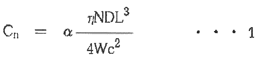
 wherein, in the formula 1, α represents a contact rate between the shaft member and the bearing member, η represents a viscosity [Pa·sec] of the lubricating oil, N represents a rotation speed [rps] of the shaft member, W represents a maximum load [N] applied from the outer peripheral face of the shaft member to the inner peripheral face of the bearing member, and c represents a radius gap [m] between the shaft member and the bearing member; in the formula 2, γ(ε) represents a roughness parameter of the outer peripheral face of the shaft member and the inner peripheral face of the bearing member, the roughness parameter being represented as a function of an eccentricity ε; and ε1 represents a value calculated according to formula 3 in a case in which an arithmetic mean roughness of the inner peripheral face of the bearing member is denoted by Ra2 [µm] and a value of a minimum oil film parameter at which the oil film maintains a fluid lubrication state is denoted by Λlim,
- The sliding member according to claim 1, whereinthe outer peripheral face of the shaft member and the inner peripheral face of the bearing member differ in hardness, andwith regard to a peripheral face having a higher hardness, the peripheral face being one of the outer peripheral face of the shaft member and the inner peripheral face of the bearing member, in a case in which an arithmetic mean roughness thereof is denoted by Rah [µm], Ra1 = Ra2 = Rah is satisfied in the formula 3.
- The sliding member according to claim 1 or 2, wherein the contact rate α is greater than or equal to 0.6.
- The sliding member according to claim 1 or 2, wherein the parameter Cn is less than a value γ(ε2) calculated based on the formula 2 by using an eccentricity ε2 calculated according to formula 4:

- A method for driving a sliding member comprising:a shaft member having a shaft diameter D of greater than or equal to 0.18 m;a bearing member which slidably supports an outer peripheral face of the shaft member; anda lubricating oil which is supplied to a gap between the outer peripheral face of the shaft member and an inner peripheral face of the bearing member and forms an oil film in the gap,the method comprising:driving by using the sliding member to rotate the shaft member, whereinan arithmetic mean roughness Ra1 of the outer peripheral face of the shaft member is less than or equal to 0.23 µm, and a protruding peak height Rpk1 of the outer peripheral face of the shaft member is less than or equal to 0.19 µm,in a case in which a width of the inner peripheral face of the bearing member in an axial direction is denoted by L [m], a width-diameter ratio calculated as L/D is less than 1, andduring steady driving in the driving, a parameter Cn calculated according to formula 1, which represents a state of the oil film, is controlled to be greater than or equal to a reference value γ(ε1) calculated based on formula 2:

 wherein, in the formula 1, α represents a contact rate between the shaft member and the bearing member, η represents a viscosity [Pa·sec] of the lubricating oil, N represents a rotation speed [rps] of the shaft member, W represents a maximum load [N] applied from the outer peripheral face of the shaft member to the inner peripheral face of the bearing member, and c represents a radius gap [m] between the shaft member and the bearing member; in the formula 2, γ(ε) represents a roughness parameter of the outer peripheral face of the shaft member and the inner peripheral face of the bearing member, the roughness parameter being represented as a function of an eccentricity ε; and ε1 represents a value calculated according to formula 3 in a case in which an arithmetic mean roughness of the inner peripheral face of the bearing member is denoted by Ra2 [µm] and a value of a minimum oil film parameter at which the oil film maintains a fluid lubrication state is denoted by Λlim,
Applications Claiming Priority (1)
| Application Number | Priority Date | Filing Date | Title |
|---|---|---|---|
| JP2021127009A JP7516322B2 (en) | 2021-08-02 | 2021-08-02 | Slide member and method for driving slide member |
Publications (2)
| Publication Number | Publication Date |
|---|---|
| EP4130498A1 true EP4130498A1 (en) | 2023-02-08 |
| EP4130498B1 EP4130498B1 (en) | 2024-03-06 |
Family
ID=82403995
Family Applications (1)
| Application Number | Title | Priority Date | Filing Date |
|---|---|---|---|
| EP22184130.7A Active EP4130498B1 (en) | 2021-08-02 | 2022-07-11 | Sliding member and method for driving sliding member |
Country Status (5)
| Country | Link |
|---|---|
| EP (1) | EP4130498B1 (en) |
| JP (1) | JP7516322B2 (en) |
| CN (1) | CN115701496B (en) |
| ES (1) | ES2975948T3 (en) |
| FI (1) | FI4130498T3 (en) |
Citations (2)
| Publication number | Priority date | Publication date | Assignee | Title |
|---|---|---|---|---|
| JPH07116958A (en) | 1993-03-09 | 1995-05-09 | Toyota Motor Corp | Method of processing the surface of the rotating shaft |
| JP2017161003A (en) * | 2016-03-10 | 2017-09-14 | 住友重機械工業株式会社 | Slide mechanism and manufacturing method of slide member |
Family Cites Families (5)
| Publication number | Priority date | Publication date | Assignee | Title |
|---|---|---|---|---|
| JPH07174136A (en) * | 1993-12-20 | 1995-07-11 | Toshiba Corp | Journal bearing |
| JPH08121485A (en) * | 1994-10-27 | 1996-05-14 | Nissan Motor Co Ltd | Crank lubrication system for internal combustion engine and manufacturing method thereof |
| DE102013109025A1 (en) | 2013-08-21 | 2015-02-26 | Mag Ias Gmbh | sliding surface |
| WO2017150609A1 (en) * | 2016-03-01 | 2017-09-08 | Ntn株式会社 | Seal-equipped bearing, and ball bearing |
| CN108799318B (en) * | 2018-06-28 | 2020-03-17 | 西安交通大学 | Design method of dynamic load bearing applied to reciprocating compressor crankshaft |
-
2021
- 2021-08-02 JP JP2021127009A patent/JP7516322B2/en active Active
-
2022
- 2022-07-11 FI FIEP22184130.7T patent/FI4130498T3/en active
- 2022-07-11 EP EP22184130.7A patent/EP4130498B1/en active Active
- 2022-07-11 ES ES22184130T patent/ES2975948T3/en active Active
- 2022-07-18 CN CN202210841496.XA patent/CN115701496B/en active Active
Patent Citations (2)
| Publication number | Priority date | Publication date | Assignee | Title |
|---|---|---|---|---|
| JPH07116958A (en) | 1993-03-09 | 1995-05-09 | Toyota Motor Corp | Method of processing the surface of the rotating shaft |
| JP2017161003A (en) * | 2016-03-10 | 2017-09-14 | 住友重機械工業株式会社 | Slide mechanism and manufacturing method of slide member |
Also Published As
| Publication number | Publication date |
|---|---|
| JP7516322B2 (en) | 2024-07-16 |
| JP2023021869A (en) | 2023-02-14 |
| CN115701496A (en) | 2023-02-10 |
| FI4130498T3 (en) | 2024-03-13 |
| EP4130498B1 (en) | 2024-03-06 |
| ES2975948T3 (en) | 2024-07-18 |
| CN115701496B (en) | 2025-03-18 |
Similar Documents
| Publication | Publication Date | Title |
|---|---|---|
| US5503481A (en) | Bearing surfaces with isotropic finish | |
| EP1433838B1 (en) | Slide member | |
| US6692155B2 (en) | Rolling sliding member, process for the production thereof and rolling sliding unit | |
| JP5057578B2 (en) | Thrust roller type thrust roller bearing | |
| EP1754898B1 (en) | Tapered roller bearing and automotive pinion shaft supporting apparatus utilizing same tapered roller bearing | |
| EP1433967B1 (en) | Angular ball bearing | |
| US5967672A (en) | Machine parts making rolling or sliding surfaces formed with discontinuous grooves | |
| JP5199728B2 (en) | Rotary compressor | |
| EP4130498B1 (en) | Sliding member and method for driving sliding member | |
| EP4102087B1 (en) | Sliding member, production method of sliding member, and evaluation method of sliding member | |
| JP7504270B2 (en) | Tapered roller bearings | |
| EP4130500B1 (en) | Bearing device and method for driving bearing device | |
| JP2009150415A (en) | Thrust roller bearing | |
| US12031577B2 (en) | Crankshaft and method of manufacturing the same | |
| JP6965005B2 (en) | Conical roller bearing | |
| JP2009150508A (en) | Thrust roller bearing | |
| JP2009150507A (en) | Thrust roller bearing | |
| JP7757195B2 (en) | Bearing device and method for driving bearing device | |
| EP4145008A1 (en) | Sliding member and method for manufacturing sliding member | |
| JP6965007B2 (en) | Conical roller bearing | |
| CN114555959A (en) | Tapered roller bearing | |
| EP4098894B1 (en) | Roller bearing | |
| Alshareef | Investigation and Modeling of Ball-Burnishing Factors Affecting Residual Stress of AISI 8620 Steel | |
| JP2009168066A (en) | Thrust roller bearing | |
| JPH02121708A (en) | Roll for adjusting crown |
Legal Events
| Date | Code | Title | Description |
|---|---|---|---|
| PUAI | Public reference made under article 153(3) epc to a published international application that has entered the european phase |
Free format text: ORIGINAL CODE: 0009012 |
|
| STAA | Information on the status of an ep patent application or granted ep patent |
Free format text: STATUS: REQUEST FOR EXAMINATION WAS MADE |
|
| 17P | Request for examination filed |
Effective date: 20220714 |
|
| AK | Designated contracting states |
Kind code of ref document: A1 Designated state(s): AL AT BE BG CH CY CZ DE DK EE ES FI FR GB GR HR HU IE IS IT LI LT LU LV MC MK MT NL NO PL PT RO RS SE SI SK SM TR |
|
| RBV | Designated contracting states (corrected) |
Designated state(s): AL AT BE BG CH CY CZ DE DK EE ES FI FR GB GR HR HU IE IS IT LI LT LU LV MC MK MT NL NO PL PT RO RS SE SI SK SM TR |
|
| GRAP | Despatch of communication of intention to grant a patent |
Free format text: ORIGINAL CODE: EPIDOSNIGR1 |
|
| STAA | Information on the status of an ep patent application or granted ep patent |
Free format text: STATUS: GRANT OF PATENT IS INTENDED |
|
| INTG | Intention to grant announced |
Effective date: 20231023 |
|
| P01 | Opt-out of the competence of the unified patent court (upc) registered |
Effective date: 20231220 |
|
| GRAS | Grant fee paid |
Free format text: ORIGINAL CODE: EPIDOSNIGR3 |
|
| GRAA | (expected) grant |
Free format text: ORIGINAL CODE: 0009210 |
|
| STAA | Information on the status of an ep patent application or granted ep patent |
Free format text: STATUS: THE PATENT HAS BEEN GRANTED |
|
| AK | Designated contracting states |
Kind code of ref document: B1 Designated state(s): AL AT BE BG CH CY CZ DE DK EE ES FI FR GB GR HR HU IE IS IT LI LT LU LV MC MK MT NL NO PL PT RO RS SE SI SK SM TR |
|
| REG | Reference to a national code |
Ref country code: FI Ref legal event code: FGE |
|
| REG | Reference to a national code |
Ref country code: CH Ref legal event code: EP |
|
| REG | Reference to a national code |
Ref country code: DE Ref legal event code: R096 Ref document number: 602022002234 Country of ref document: DE |
|
| REG | Reference to a national code |
Ref country code: IE Ref legal event code: FG4D |
|
| REG | Reference to a national code |
Ref country code: LT Ref legal event code: MG9D |
|
| PG25 | Lapsed in a contracting state [announced via postgrant information from national office to epo] |
Ref country code: LT Free format text: LAPSE BECAUSE OF FAILURE TO SUBMIT A TRANSLATION OF THE DESCRIPTION OR TO PAY THE FEE WITHIN THE PRESCRIBED TIME-LIMIT Effective date: 20240306 |
|
| REG | Reference to a national code |
Ref country code: NL Ref legal event code: MP Effective date: 20240306 |
|
| PG25 | Lapsed in a contracting state [announced via postgrant information from national office to epo] |
Ref country code: GR Free format text: LAPSE BECAUSE OF FAILURE TO SUBMIT A TRANSLATION OF THE DESCRIPTION OR TO PAY THE FEE WITHIN THE PRESCRIBED TIME-LIMIT Effective date: 20240607 |
|
| PG25 | Lapsed in a contracting state [announced via postgrant information from national office to epo] |
Ref country code: RS Free format text: LAPSE BECAUSE OF FAILURE TO SUBMIT A TRANSLATION OF THE DESCRIPTION OR TO PAY THE FEE WITHIN THE PRESCRIBED TIME-LIMIT Effective date: 20240606 Ref country code: HR Free format text: LAPSE BECAUSE OF FAILURE TO SUBMIT A TRANSLATION OF THE DESCRIPTION OR TO PAY THE FEE WITHIN THE PRESCRIBED TIME-LIMIT Effective date: 20240306 |
|
| REG | Reference to a national code |
Ref country code: ES Ref legal event code: FG2A Ref document number: 2975948 Country of ref document: ES Kind code of ref document: T3 Effective date: 20240718 |
|
| PG25 | Lapsed in a contracting state [announced via postgrant information from national office to epo] |
Ref country code: RS Free format text: LAPSE BECAUSE OF FAILURE TO SUBMIT A TRANSLATION OF THE DESCRIPTION OR TO PAY THE FEE WITHIN THE PRESCRIBED TIME-LIMIT Effective date: 20240606 Ref country code: LT Free format text: LAPSE BECAUSE OF FAILURE TO SUBMIT A TRANSLATION OF THE DESCRIPTION OR TO PAY THE FEE WITHIN THE PRESCRIBED TIME-LIMIT Effective date: 20240306 Ref country code: HR Free format text: LAPSE BECAUSE OF FAILURE TO SUBMIT A TRANSLATION OF THE DESCRIPTION OR TO PAY THE FEE WITHIN THE PRESCRIBED TIME-LIMIT Effective date: 20240306 Ref country code: GR Free format text: LAPSE BECAUSE OF FAILURE TO SUBMIT A TRANSLATION OF THE DESCRIPTION OR TO PAY THE FEE WITHIN THE PRESCRIBED TIME-LIMIT Effective date: 20240607 Ref country code: BG Free format text: LAPSE BECAUSE OF FAILURE TO SUBMIT A TRANSLATION OF THE DESCRIPTION OR TO PAY THE FEE WITHIN THE PRESCRIBED TIME-LIMIT Effective date: 20240306 |
|
| REG | Reference to a national code |
Ref country code: AT Ref legal event code: MK05 Ref document number: 1663782 Country of ref document: AT Kind code of ref document: T Effective date: 20240306 |
|
| PG25 | Lapsed in a contracting state [announced via postgrant information from national office to epo] |
Ref country code: SE Free format text: LAPSE BECAUSE OF FAILURE TO SUBMIT A TRANSLATION OF THE DESCRIPTION OR TO PAY THE FEE WITHIN THE PRESCRIBED TIME-LIMIT Effective date: 20240306 Ref country code: LV Free format text: LAPSE BECAUSE OF FAILURE TO SUBMIT A TRANSLATION OF THE DESCRIPTION OR TO PAY THE FEE WITHIN THE PRESCRIBED TIME-LIMIT Effective date: 20240306 |
|
| PG25 | Lapsed in a contracting state [announced via postgrant information from national office to epo] |
Ref country code: NL Free format text: LAPSE BECAUSE OF FAILURE TO SUBMIT A TRANSLATION OF THE DESCRIPTION OR TO PAY THE FEE WITHIN THE PRESCRIBED TIME-LIMIT Effective date: 20240306 |
|
| PG25 | Lapsed in a contracting state [announced via postgrant information from national office to epo] |
Ref country code: NL Free format text: LAPSE BECAUSE OF FAILURE TO SUBMIT A TRANSLATION OF THE DESCRIPTION OR TO PAY THE FEE WITHIN THE PRESCRIBED TIME-LIMIT Effective date: 20240306 |
|
| PG25 | Lapsed in a contracting state [announced via postgrant information from national office to epo] |
Ref country code: IS Free format text: LAPSE BECAUSE OF FAILURE TO SUBMIT A TRANSLATION OF THE DESCRIPTION OR TO PAY THE FEE WITHIN THE PRESCRIBED TIME-LIMIT Effective date: 20240706 |
|
| PG25 | Lapsed in a contracting state [announced via postgrant information from national office to epo] |
Ref country code: SM Free format text: LAPSE BECAUSE OF FAILURE TO SUBMIT A TRANSLATION OF THE DESCRIPTION OR TO PAY THE FEE WITHIN THE PRESCRIBED TIME-LIMIT Effective date: 20240306 Ref country code: PT Free format text: LAPSE BECAUSE OF FAILURE TO SUBMIT A TRANSLATION OF THE DESCRIPTION OR TO PAY THE FEE WITHIN THE PRESCRIBED TIME-LIMIT Effective date: 20240708 |
|
| PG25 | Lapsed in a contracting state [announced via postgrant information from national office to epo] |
Ref country code: CZ Free format text: LAPSE BECAUSE OF FAILURE TO SUBMIT A TRANSLATION OF THE DESCRIPTION OR TO PAY THE FEE WITHIN THE PRESCRIBED TIME-LIMIT Effective date: 20240306 Ref country code: EE Free format text: LAPSE BECAUSE OF FAILURE TO SUBMIT A TRANSLATION OF THE DESCRIPTION OR TO PAY THE FEE WITHIN THE PRESCRIBED TIME-LIMIT Effective date: 20240306 |
|
| PG25 | Lapsed in a contracting state [announced via postgrant information from national office to epo] |
Ref country code: AT Free format text: LAPSE BECAUSE OF FAILURE TO SUBMIT A TRANSLATION OF THE DESCRIPTION OR TO PAY THE FEE WITHIN THE PRESCRIBED TIME-LIMIT Effective date: 20240306 |
|
| PG25 | Lapsed in a contracting state [announced via postgrant information from national office to epo] |
Ref country code: PL Free format text: LAPSE BECAUSE OF FAILURE TO SUBMIT A TRANSLATION OF THE DESCRIPTION OR TO PAY THE FEE WITHIN THE PRESCRIBED TIME-LIMIT Effective date: 20240306 |
|
| PG25 | Lapsed in a contracting state [announced via postgrant information from national office to epo] |
Ref country code: SK Free format text: LAPSE BECAUSE OF FAILURE TO SUBMIT A TRANSLATION OF THE DESCRIPTION OR TO PAY THE FEE WITHIN THE PRESCRIBED TIME-LIMIT Effective date: 20240306 |
|
| PG25 | Lapsed in a contracting state [announced via postgrant information from national office to epo] |
Ref country code: SM Free format text: LAPSE BECAUSE OF FAILURE TO SUBMIT A TRANSLATION OF THE DESCRIPTION OR TO PAY THE FEE WITHIN THE PRESCRIBED TIME-LIMIT Effective date: 20240306 Ref country code: SK Free format text: LAPSE BECAUSE OF FAILURE TO SUBMIT A TRANSLATION OF THE DESCRIPTION OR TO PAY THE FEE WITHIN THE PRESCRIBED TIME-LIMIT Effective date: 20240306 Ref country code: RO Free format text: LAPSE BECAUSE OF FAILURE TO SUBMIT A TRANSLATION OF THE DESCRIPTION OR TO PAY THE FEE WITHIN THE PRESCRIBED TIME-LIMIT Effective date: 20240306 Ref country code: PT Free format text: LAPSE BECAUSE OF FAILURE TO SUBMIT A TRANSLATION OF THE DESCRIPTION OR TO PAY THE FEE WITHIN THE PRESCRIBED TIME-LIMIT Effective date: 20240708 Ref country code: PL Free format text: LAPSE BECAUSE OF FAILURE TO SUBMIT A TRANSLATION OF THE DESCRIPTION OR TO PAY THE FEE WITHIN THE PRESCRIBED TIME-LIMIT Effective date: 20240306 Ref country code: IS Free format text: LAPSE BECAUSE OF FAILURE TO SUBMIT A TRANSLATION OF THE DESCRIPTION OR TO PAY THE FEE WITHIN THE PRESCRIBED TIME-LIMIT Effective date: 20240706 Ref country code: EE Free format text: LAPSE BECAUSE OF FAILURE TO SUBMIT A TRANSLATION OF THE DESCRIPTION OR TO PAY THE FEE WITHIN THE PRESCRIBED TIME-LIMIT Effective date: 20240306 Ref country code: CZ Free format text: LAPSE BECAUSE OF FAILURE TO SUBMIT A TRANSLATION OF THE DESCRIPTION OR TO PAY THE FEE WITHIN THE PRESCRIBED TIME-LIMIT Effective date: 20240306 Ref country code: AT Free format text: LAPSE BECAUSE OF FAILURE TO SUBMIT A TRANSLATION OF THE DESCRIPTION OR TO PAY THE FEE WITHIN THE PRESCRIBED TIME-LIMIT Effective date: 20240306 |
|
| PG25 | Lapsed in a contracting state [announced via postgrant information from national office to epo] |
Ref country code: IT Free format text: LAPSE BECAUSE OF FAILURE TO SUBMIT A TRANSLATION OF THE DESCRIPTION OR TO PAY THE FEE WITHIN THE PRESCRIBED TIME-LIMIT Effective date: 20240306 |
|
| REG | Reference to a national code |
Ref country code: DE Ref legal event code: R097 Ref document number: 602022002234 Country of ref document: DE |
|
| PG25 | Lapsed in a contracting state [announced via postgrant information from national office to epo] |
Ref country code: IT Free format text: LAPSE BECAUSE OF FAILURE TO SUBMIT A TRANSLATION OF THE DESCRIPTION OR TO PAY THE FEE WITHIN THE PRESCRIBED TIME-LIMIT Effective date: 20240306 |
|
| PLBE | No opposition filed within time limit |
Free format text: ORIGINAL CODE: 0009261 |
|
| STAA | Information on the status of an ep patent application or granted ep patent |
Free format text: STATUS: NO OPPOSITION FILED WITHIN TIME LIMIT |
|
| PG25 | Lapsed in a contracting state [announced via postgrant information from national office to epo] |
Ref country code: DK Free format text: LAPSE BECAUSE OF FAILURE TO SUBMIT A TRANSLATION OF THE DESCRIPTION OR TO PAY THE FEE WITHIN THE PRESCRIBED TIME-LIMIT Effective date: 20240306 |
|
| PG25 | Lapsed in a contracting state [announced via postgrant information from national office to epo] |
Ref country code: DK Free format text: LAPSE BECAUSE OF FAILURE TO SUBMIT A TRANSLATION OF THE DESCRIPTION OR TO PAY THE FEE WITHIN THE PRESCRIBED TIME-LIMIT Effective date: 20240306 |
|
| PG25 | Lapsed in a contracting state [announced via postgrant information from national office to epo] |
Ref country code: MC Free format text: LAPSE BECAUSE OF FAILURE TO SUBMIT A TRANSLATION OF THE DESCRIPTION OR TO PAY THE FEE WITHIN THE PRESCRIBED TIME-LIMIT Effective date: 20240306 |
|
| 26N | No opposition filed |
Effective date: 20241209 |
|
| PG25 | Lapsed in a contracting state [announced via postgrant information from national office to epo] |
Ref country code: LU Free format text: LAPSE BECAUSE OF NON-PAYMENT OF DUE FEES Effective date: 20240711 |
|
| PG25 | Lapsed in a contracting state [announced via postgrant information from national office to epo] |
Ref country code: LU Free format text: LAPSE BECAUSE OF NON-PAYMENT OF DUE FEES Effective date: 20240711 |
|
| PG25 | Lapsed in a contracting state [announced via postgrant information from national office to epo] |
Ref country code: SI Free format text: LAPSE BECAUSE OF FAILURE TO SUBMIT A TRANSLATION OF THE DESCRIPTION OR TO PAY THE FEE WITHIN THE PRESCRIBED TIME-LIMIT Effective date: 20240306 Ref country code: BE Free format text: LAPSE BECAUSE OF NON-PAYMENT OF DUE FEES Effective date: 20240731 |
|
| PG25 | Lapsed in a contracting state [announced via postgrant information from national office to epo] |
Ref country code: FR Free format text: LAPSE BECAUSE OF NON-PAYMENT OF DUE FEES Effective date: 20240731 |
|
| REG | Reference to a national code |
Ref country code: BE Ref legal event code: MM Effective date: 20240731 |
|
| PG25 | Lapsed in a contracting state [announced via postgrant information from national office to epo] |
Ref country code: IE Free format text: LAPSE BECAUSE OF NON-PAYMENT OF DUE FEES Effective date: 20240711 |
|
| PGFP | Annual fee paid to national office [announced via postgrant information from national office to epo] |
Ref country code: ES Payment date: 20250804 Year of fee payment: 4 Ref country code: FI Payment date: 20250715 Year of fee payment: 4 |
|
| PGFP | Annual fee paid to national office [announced via postgrant information from national office to epo] |
Ref country code: DE Payment date: 20250604 Year of fee payment: 4 |
|
| PGFP | Annual fee paid to national office [announced via postgrant information from national office to epo] |
Ref country code: NO Payment date: 20250709 Year of fee payment: 4 |
|
| PG25 | Lapsed in a contracting state [announced via postgrant information from national office to epo] |
Ref country code: CY Free format text: LAPSE BECAUSE OF FAILURE TO SUBMIT A TRANSLATION OF THE DESCRIPTION OR TO PAY THE FEE WITHIN THE PRESCRIBED TIME-LIMIT; INVALID AB INITIO Effective date: 20220711 |
|
| REG | Reference to a national code |
Ref country code: CH Ref legal event code: H13 Free format text: ST27 STATUS EVENT CODE: U-0-0-H10-H13 (AS PROVIDED BY THE NATIONAL OFFICE) Effective date: 20260224 |
|
| PG25 | Lapsed in a contracting state [announced via postgrant information from national office to epo] |
Ref country code: HU Free format text: LAPSE BECAUSE OF FAILURE TO SUBMIT A TRANSLATION OF THE DESCRIPTION OR TO PAY THE FEE WITHIN THE PRESCRIBED TIME-LIMIT; INVALID AB INITIO Effective date: 20220711 |
|
| PG25 | Lapsed in a contracting state [announced via postgrant information from national office to epo] |
Ref country code: CH Free format text: LAPSE BECAUSE OF NON-PAYMENT OF DUE FEES Effective date: 20250731 |
|
| PG25 | Lapsed in a contracting state [announced via postgrant information from national office to epo] |
Ref country code: TR Free format text: LAPSE BECAUSE OF FAILURE TO SUBMIT A TRANSLATION OF THE DESCRIPTION OR TO PAY THE FEE WITHIN THE PRESCRIBED TIME-LIMIT Effective date: 20240306 |
|
| PG25 | Lapsed in a contracting state [announced via postgrant information from national office to epo] |
Ref country code: CH Free format text: THE PATENT HAS BEEN ANNULLED BY A DECISION OF A NATIONAL AUTHORITY Effective date: 20250731 |